US8362992B2 - Dual view display system using a transparent display - Google Patents
Dual view display system using a transparent displayDownload PDFInfo
- Publication number
- US8362992B2 US8362992B2US12/840,576US84057610AUS8362992B2US 8362992 B2US8362992 B2US 8362992B2US 84057610 AUS84057610 AUS 84057610AUS 8362992 B2US8362992 B2US 8362992B2
- Authority
- US
- United States
- Prior art keywords
- image
- display
- time period
- shutter device
- view
- Prior art date
- Legal status (The legal status is an assumption and is not a legal conclusion. Google has not performed a legal analysis and makes no representation as to the accuracy of the status listed.)
- Active, expires
Links
Images


Classifications
- G—PHYSICS
- G02—OPTICS
- G02F—OPTICAL DEVICES OR ARRANGEMENTS FOR THE CONTROL OF LIGHT BY MODIFICATION OF THE OPTICAL PROPERTIES OF THE MEDIA OF THE ELEMENTS INVOLVED THEREIN; NON-LINEAR OPTICS; FREQUENCY-CHANGING OF LIGHT; OPTICAL LOGIC ELEMENTS; OPTICAL ANALOGUE/DIGITAL CONVERTERS
- G02F1/00—Devices or arrangements for the control of the intensity, colour, phase, polarisation or direction of light arriving from an independent light source, e.g. switching, gating or modulating; Non-linear optics
- G02F1/01—Devices or arrangements for the control of the intensity, colour, phase, polarisation or direction of light arriving from an independent light source, e.g. switching, gating or modulating; Non-linear optics for the control of the intensity, phase, polarisation or colour
- G02F1/13—Devices or arrangements for the control of the intensity, colour, phase, polarisation or direction of light arriving from an independent light source, e.g. switching, gating or modulating; Non-linear optics for the control of the intensity, phase, polarisation or colour based on liquid crystals, e.g. single liquid crystal display cells
- G02F1/133—Constructional arrangements; Operation of liquid crystal cells; Circuit arrangements
- G02F1/1333—Constructional arrangements; Manufacturing methods
- G02F1/1347—Arrangement of liquid crystal layers or cells in which the final condition of one light beam is achieved by the addition of the effects of two or more layers or cells
- G—PHYSICS
- G02—OPTICS
- G02F—OPTICAL DEVICES OR ARRANGEMENTS FOR THE CONTROL OF LIGHT BY MODIFICATION OF THE OPTICAL PROPERTIES OF THE MEDIA OF THE ELEMENTS INVOLVED THEREIN; NON-LINEAR OPTICS; FREQUENCY-CHANGING OF LIGHT; OPTICAL LOGIC ELEMENTS; OPTICAL ANALOGUE/DIGITAL CONVERTERS
- G02F1/00—Devices or arrangements for the control of the intensity, colour, phase, polarisation or direction of light arriving from an independent light source, e.g. switching, gating or modulating; Non-linear optics
- G02F1/01—Devices or arrangements for the control of the intensity, colour, phase, polarisation or direction of light arriving from an independent light source, e.g. switching, gating or modulating; Non-linear optics for the control of the intensity, phase, polarisation or colour
- G02F1/13—Devices or arrangements for the control of the intensity, colour, phase, polarisation or direction of light arriving from an independent light source, e.g. switching, gating or modulating; Non-linear optics for the control of the intensity, phase, polarisation or colour based on liquid crystals, e.g. single liquid crystal display cells
- G02F1/133—Constructional arrangements; Operation of liquid crystal cells; Circuit arrangements
- G02F1/13306—Circuit arrangements or driving methods for the control of single liquid crystal cells
- G—PHYSICS
- G09—EDUCATION; CRYPTOGRAPHY; DISPLAY; ADVERTISING; SEALS
- G09G—ARRANGEMENTS OR CIRCUITS FOR CONTROL OF INDICATING DEVICES USING STATIC MEANS TO PRESENT VARIABLE INFORMATION
- G09G3/00—Control arrangements or circuits, of interest only in connection with visual indicators other than cathode-ray tubes
- G09G3/001—Control arrangements or circuits, of interest only in connection with visual indicators other than cathode-ray tubes using specific devices not provided for in groups G09G3/02 - G09G3/36, e.g. using an intermediate record carrier such as a film slide; Projection systems; Display of non-alphanumerical information, solely or in combination with alphanumerical information, e.g. digital display on projected diapositive as background
- G09G3/003—Control arrangements or circuits, of interest only in connection with visual indicators other than cathode-ray tubes using specific devices not provided for in groups G09G3/02 - G09G3/36, e.g. using an intermediate record carrier such as a film slide; Projection systems; Display of non-alphanumerical information, solely or in combination with alphanumerical information, e.g. digital display on projected diapositive as background to produce spatial visual effects
- G—PHYSICS
- G09—EDUCATION; CRYPTOGRAPHY; DISPLAY; ADVERTISING; SEALS
- G09G—ARRANGEMENTS OR CIRCUITS FOR CONTROL OF INDICATING DEVICES USING STATIC MEANS TO PRESENT VARIABLE INFORMATION
- G09G3/00—Control arrangements or circuits, of interest only in connection with visual indicators other than cathode-ray tubes
- G09G3/20—Control arrangements or circuits, of interest only in connection with visual indicators other than cathode-ray tubes for presentation of an assembly of a number of characters, e.g. a page, by composing the assembly by combination of individual elements arranged in a matrix no fixed position being assigned to or needed to be assigned to the individual characters or partial characters
- G09G3/34—Control arrangements or circuits, of interest only in connection with visual indicators other than cathode-ray tubes for presentation of an assembly of a number of characters, e.g. a page, by composing the assembly by combination of individual elements arranged in a matrix no fixed position being assigned to or needed to be assigned to the individual characters or partial characters by control of light from an independent source
- G09G3/36—Control arrangements or circuits, of interest only in connection with visual indicators other than cathode-ray tubes for presentation of an assembly of a number of characters, e.g. a page, by composing the assembly by combination of individual elements arranged in a matrix no fixed position being assigned to or needed to be assigned to the individual characters or partial characters by control of light from an independent source using liquid crystals
- G—PHYSICS
- G02—OPTICS
- G02F—OPTICAL DEVICES OR ARRANGEMENTS FOR THE CONTROL OF LIGHT BY MODIFICATION OF THE OPTICAL PROPERTIES OF THE MEDIA OF THE ELEMENTS INVOLVED THEREIN; NON-LINEAR OPTICS; FREQUENCY-CHANGING OF LIGHT; OPTICAL LOGIC ELEMENTS; OPTICAL ANALOGUE/DIGITAL CONVERTERS
- G02F1/00—Devices or arrangements for the control of the intensity, colour, phase, polarisation or direction of light arriving from an independent light source, e.g. switching, gating or modulating; Non-linear optics
- G02F1/01—Devices or arrangements for the control of the intensity, colour, phase, polarisation or direction of light arriving from an independent light source, e.g. switching, gating or modulating; Non-linear optics for the control of the intensity, phase, polarisation or colour
- G02F1/13—Devices or arrangements for the control of the intensity, colour, phase, polarisation or direction of light arriving from an independent light source, e.g. switching, gating or modulating; Non-linear optics for the control of the intensity, phase, polarisation or colour based on liquid crystals, e.g. single liquid crystal display cells
- G02F1/133—Constructional arrangements; Operation of liquid crystal cells; Circuit arrangements
- G02F1/1333—Constructional arrangements; Manufacturing methods
- G02F1/133342—Constructional arrangements; Manufacturing methods for double-sided displays
- G—PHYSICS
- G02—OPTICS
- G02F—OPTICAL DEVICES OR ARRANGEMENTS FOR THE CONTROL OF LIGHT BY MODIFICATION OF THE OPTICAL PROPERTIES OF THE MEDIA OF THE ELEMENTS INVOLVED THEREIN; NON-LINEAR OPTICS; FREQUENCY-CHANGING OF LIGHT; OPTICAL LOGIC ELEMENTS; OPTICAL ANALOGUE/DIGITAL CONVERTERS
- G02F1/00—Devices or arrangements for the control of the intensity, colour, phase, polarisation or direction of light arriving from an independent light source, e.g. switching, gating or modulating; Non-linear optics
- G02F1/01—Devices or arrangements for the control of the intensity, colour, phase, polarisation or direction of light arriving from an independent light source, e.g. switching, gating or modulating; Non-linear optics for the control of the intensity, phase, polarisation or colour
- G02F1/13—Devices or arrangements for the control of the intensity, colour, phase, polarisation or direction of light arriving from an independent light source, e.g. switching, gating or modulating; Non-linear optics for the control of the intensity, phase, polarisation or colour based on liquid crystals, e.g. single liquid crystal display cells
- G02F1/133—Constructional arrangements; Operation of liquid crystal cells; Circuit arrangements
- G02F1/1333—Constructional arrangements; Manufacturing methods
- G02F1/13338—Input devices, e.g. touch panels
- G—PHYSICS
- G09—EDUCATION; CRYPTOGRAPHY; DISPLAY; ADVERTISING; SEALS
- G09G—ARRANGEMENTS OR CIRCUITS FOR CONTROL OF INDICATING DEVICES USING STATIC MEANS TO PRESENT VARIABLE INFORMATION
- G09G2300/00—Aspects of the constitution of display devices
- G09G2300/02—Composition of display devices
- G09G2300/023—Display panel composed of stacked panels
- G—PHYSICS
- G09—EDUCATION; CRYPTOGRAPHY; DISPLAY; ADVERTISING; SEALS
- G09G—ARRANGEMENTS OR CIRCUITS FOR CONTROL OF INDICATING DEVICES USING STATIC MEANS TO PRESENT VARIABLE INFORMATION
- G09G3/00—Control arrangements or circuits, of interest only in connection with visual indicators other than cathode-ray tubes
- G09G3/20—Control arrangements or circuits, of interest only in connection with visual indicators other than cathode-ray tubes for presentation of an assembly of a number of characters, e.g. a page, by composing the assembly by combination of individual elements arranged in a matrix no fixed position being assigned to or needed to be assigned to the individual characters or partial characters
- G09G3/34—Control arrangements or circuits, of interest only in connection with visual indicators other than cathode-ray tubes for presentation of an assembly of a number of characters, e.g. a page, by composing the assembly by combination of individual elements arranged in a matrix no fixed position being assigned to or needed to be assigned to the individual characters or partial characters by control of light from an independent source
- G09G3/3433—Control arrangements or circuits, of interest only in connection with visual indicators other than cathode-ray tubes for presentation of an assembly of a number of characters, e.g. a page, by composing the assembly by combination of individual elements arranged in a matrix no fixed position being assigned to or needed to be assigned to the individual characters or partial characters by control of light from an independent source using light modulating elements actuated by an electric field and being other than liquid crystal devices and electrochromic devices
- G09G3/348—Control arrangements or circuits, of interest only in connection with visual indicators other than cathode-ray tubes for presentation of an assembly of a number of characters, e.g. a page, by composing the assembly by combination of individual elements arranged in a matrix no fixed position being assigned to or needed to be assigned to the individual characters or partial characters by control of light from an independent source using light modulating elements actuated by an electric field and being other than liquid crystal devices and electrochromic devices based on the deformation of a fluid drop, e.g. electrowetting
- G—PHYSICS
- G09—EDUCATION; CRYPTOGRAPHY; DISPLAY; ADVERTISING; SEALS
- G09G—ARRANGEMENTS OR CIRCUITS FOR CONTROL OF INDICATING DEVICES USING STATIC MEANS TO PRESENT VARIABLE INFORMATION
- G09G3/00—Control arrangements or circuits, of interest only in connection with visual indicators other than cathode-ray tubes
- G09G3/20—Control arrangements or circuits, of interest only in connection with visual indicators other than cathode-ray tubes for presentation of an assembly of a number of characters, e.g. a page, by composing the assembly by combination of individual elements arranged in a matrix no fixed position being assigned to or needed to be assigned to the individual characters or partial characters
- G09G3/34—Control arrangements or circuits, of interest only in connection with visual indicators other than cathode-ray tubes for presentation of an assembly of a number of characters, e.g. a page, by composing the assembly by combination of individual elements arranged in a matrix no fixed position being assigned to or needed to be assigned to the individual characters or partial characters by control of light from an independent source
- G09G3/38—Control arrangements or circuits, of interest only in connection with visual indicators other than cathode-ray tubes for presentation of an assembly of a number of characters, e.g. a page, by composing the assembly by combination of individual elements arranged in a matrix no fixed position being assigned to or needed to be assigned to the individual characters or partial characters by control of light from an independent source using electrochromic devices
Definitions
- the inventiongenerally relates to displays for displaying images or information, and more particularly relates to a system that time-multiplexes a single transparent display with different images, and uses light valves or shutter devices to display different images in substantially opposite directions from opposite sides of the transparent display.
- Transparent panel type displayscapable of being viewed from substantially opposite sides are known.
- a transparent organic light emitting diode (OLED) type displaynaturally emits light from both sides of the display.
- Such displaysare available from Samsung, NeoView Kolon, and others.
- Other examplesinclude transparent electroluminescent (EL) displays and transparent liquid crystal display (LCD). While such displays may be viewed from either side, the image on one side is typically a mirror or reverse image of the opposite side, and so makes the viewing images such as text or asymmetrical objects difficult for the person seeing the mirrored or reversed image.
- Described hereinis a dual view display system that uses a single transparent display to display two different images on opposite side of the display system.
- the projected imagesare time-multiplexed, and shutter devices on each side of the transparent display are used to allow or block viewing of the display in accordance with the time-multiplexing so that the images viewed on both sides is properly oriented.
- a dual view display system 10for displaying properly oriented images in substantially opposite directions.
- the systemincludes a transparent display, a first shutter device, and a second shutter device.
- the transparent displayis configured display a first image oriented for a first side during a first time period and display a second image oriented for a second side opposite the first side during a second time period distinct from the first time period.
- the first shutter deviceis configured to allow a view of the first side during the first time period, and block the view of the first side during the second time period.
- the second shutter deviceconfigured to allow a view of the second side during the second time period, and block the view of the second side during the first time period.
- the first shutter deviceis a first liquid crystal device (LCD)
- the second shutter deviceis a second LCD device.
- the systemincludes a touch sensitive surface configured to determine that an object is touching the system to indicate a location in the first image.
- the systemis further configured to indicate a corresponding location on the second image.
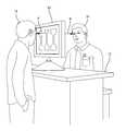
- FIG. 1is a perspective view of an exemplary service counter equipped with a dual view display system in accordance with one embodiment
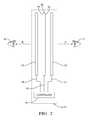
- FIG. 2is a diagram of a multiple view display system in accordance with one embodiment.
- FIGS. 3A and 3Bare front and back views of information displayed by the dual view display system of FIG. 1 in accordance with one embodiment.
- FIG. 1illustrates a non-limiting example of the system 10 positioned on a service counter 12 at a retail store, for example an automotive parts store.
- displaying properly oriented imagesmeans that the dual view display system 10 includes features to overcome the problem of the images on the opposite sides of the transparent display being reversed or mirror images of each other, as will be described in more detail below.
- the system 10is configured so that, as illustrated in this example, a customer 14 and a sales person 16 can view information from opposite direction A and B on opposite sides of the dual view display system 10 .
- the customer 14may be desirable for the customer 14 to view the same information that is viewed by the sales person 16 , for example to identify an automotive part the customer 14 wants to purchase.
- Positioning the dual view display system 10 so that the customer 14 and sales person 16 are both provided with a convenient displayavoids inconveniences such as having to share a single view display by swiveling the display back and forth between directions A and B, or the customer 14 and sales person 16 having to lean over the counter 12 toward each other so both can view the single view display from a direction somewhere between directions A and B.
- the information on the display viewed by the customer 14may be a subset of the information on the display viewed by the sales person 16 , such as a zoomed in image of an automotive part, or the image displayed to the customer 14 not showing part numbers or stocking information that may be shown to the sales person 16 .
- Other situations where the dual view display system 10 may be usefulinclude displaying to customers (not shown) unrelated information on opposite sides of a retail display such as adjacent isles in a grocery store, or displaying gaming information to opponents (not shown) competing in an interactive video game. It should be apparent that such a dual view display system 10 will be useful to display information to individuals that are interacting in numerous ways, or in situations where there is no interaction between the persons viewing the opposite sides of the dual view display system 10
- FIG. 2shows a diagram of an embodiment of a dual view display system 10 configured to display a first image in a direction A, and a second image in a second direction B.
- the first imageis preferably oriented for viewing from a first side 22 of the transparent display 20
- the second imageis preferably oriented for viewing from a second side 24 .
- the dual view display system 10may be configured to display distinct images in substantially opposite directions A and B. Providing such a feature may include time-multiplexing the images.
- Time-multiplexingmay include the transparent display 20 displaying a first image oriented for viewing on the first side 22 from the first direction A during a first time period and displaying a second image oriented for viewing on a second side 24 opposite the first side 22 from a second direction B substantially opposite the first direction A during a second time period distinct from the first time period.
- substantially opposite directions A and Bmeans that images are viewed from positions on opposite sides of a plane defined by the dual view display system 10 .
- the dual view display system 10may include a first shutter device 32 configured to allow a view of the first side 22 from the first direction A during the first time period, and to block or obstruct the view of the first side 22 during the second time period.
- the dual view display system 10may also include a second shutter device 34 configured to allow a view of the second side 24 from the second direction B during the second time period, and block the view of the second side 24 during the first time period.
- the shutter devices 32 and 34are operated as light valves to transmit or block the propagation of light.
- FIG. 2shows the shutter devices 32 and 34 spaced apart from the transparent display 20 only for the purposes of illustration. It will be recognized by those skilled in the art that the transparent display 20 and the shutter devices may in contact and so minimize the thickness of the dual view display system 10 .
- FIGS. 1-2depict the transparent display 20 as being flat, however is will be recognized that since flexible transparent display are available, the dual view display system 10 may be curved or otherwise shaped for applications where a non-flat display would be advantageous.
- FIGS. 1 - 2also depict the display areas on opposite sides of the dual view display system 10 as being about equal, however it will be appreciated that the display area on one side could be different that the display area on the other side.
- the shutter devices 32 and 34may each include a liquid crystal device (LCD).
- LCDliquid crystal device
- an LCDmay be operated to a transparent state or OFF state so that an image displayed by the transparent display 20 may be viewed through the LCD.
- the LCDmay also be operated to an opaque state or ON state so that the image can not be viewed through the LCD.
- the LCD devicemay have a single element sized to correspond to the transparent display 20 , or may have a plurality of elements so that portions of the transparent display can be independently viewed or blocked from being viewed.
- the shutter devices 32 and 34may be electrowetting type devices operable to a transparent state or an opaque state.
- the shutter devices 32 and 34may be electrochromic glass type devices operable to a transparent state or an opaque state.
- Other suitable devices for use as shutter devices 32 and/or 34include an electrically switchable transreflective mirror (ESTM).
- ESTM'sare known devices available from Kent Optronics that are operable to a reflection state whereby light impinging on the ESTM is reflected, and operable to a transparent state whereby light passes though the ESTM. It will be appreciated that the shutter devices 32 and 34 do not need to be the same technology, and so it may be advantageous to have one shutter device be one technology, for example an ESTM, and the other shutter device be a different technology, for example an LCD.
- the arrangement of the transparent display 20 and the two shutter devices 32 and 34 illustrated in FIG. 2suggests that the three components are not integrated in any particular manner, other than just placing them in proximity of each other, to form a two sided display.
- the cost of the two sided display arrangementmay be reduced and the performance improved by integrally fabricating the two sided display to have the features of the transparent display 20 and the two shutter devices 32 and 34 in a single device.
- such a two sided displaymay be fabricated by starting with a known transparent display, such as an organic light emitting diode (OLED) display, and then applying additional layers of material to the glass outer surfaces of the OLED display to form the shutter devices.
- the additional layer of materialmay be known materials used to form electrowetting cells.
- Integrally fabricating as two sided display in such a manneris advantageous in that it reduces cost and weight by eliminating redundant layers of glass present when separate components are just placed together, and improves the optical properties of the two sided display by eliminating the potential of an air gap being present between the separate components.
- a shutter device based on electrowetting technologymay be a single cell covering the entire area of the two sided display, or multiple cells or pixels capable of selectively blocking portions of the transparent display within the two sided display.
- the system 10may include a controller 40 adapted to provide an image control signal 42 for controlling the time-multiplexing of images shown by the transparent display 20 .
- the controller 40may also be adapted to provide a first shutter control signal 42 for controlling the first shutter device 32 , and a second shutter control signal 46 for controlling the second shutter device 46 in coordination with the images being displayed by the transparent display 20 .
- the controller 40may include a processor such as a microprocessor or other control circuitry as should be evident to those in the art.
- the controller 40may include memory, including non-volatile memory, such as electrically erasable programmable read-only memory (EEPROM) for storing one or more routines, thresholds and captured data. The one or more routines may be executed by the processor to perform steps for providing signals 42 , 44 , and 46 as described herein.
- EEPROMelectrically erasable programmable read-only memory
- the shutter control signals 44 and 46are shown as independent signals since it may be desirable to provide a delay time between one shutter device switching from the transparent state (OFF) to the opaque state (ON) and the other shutter device switching from ON to OFF. This delay time may be desirable so the transparent display 20 can completely update the image before a shutter device is turned OFF so the image can be viewed. Alternatively, the shutter control signals 44 and 46 may be combined into a single signal and any necessary time delays be provided by the shutter devices 32 and 34 .
- both shutter devicesmay be turned off so the transparent display can be viewed from both sides simultaneously, even though the view from the first direction A is a mirror image of the view from the second direction B.
- Such a mode of operationmay be useful so one viewer can determine if some detail being displayed is being pointed to by the other viewer.
- the first shutter device 32may be further configured to allow a view of the first side 22 during a third time period and the second shutter device 34 may be further configured to allow a view of the second side 24 during the third time period, whereby the first image is a mirror image of the second image. Referring FIG. 1 , in such a mode of operation, the customer 14 would see a mirror image of what is seen by the sales person 16 .
- the dual view display system 10may have touch screen capability so the customer 14 or sales person 16 can make a selection or other indication by bringing a pointing device such as an indicator pen or finger tip near to or in contact with the dual view display system 10 .
- the system 10may include a proximity detector configured to determine that an object such as a finger tip is indicating a location on the dual view display system 10 .
- a proximity detectormay be an ultrasonic transducer, an infrared detector, a grid of light beams, or a touch sensitive screen.
- the dual view display system 10may also be desirable for the dual view display system 10 to include an indication means configured to provide an indication that a location on one side of the system is being touched or pointed to by providing an indication at a corresponding location on the other side of the system 10 .
- FIG. 3illustrates an exemplary embodiment of the dual view display system 10 displaying a first image 26 on the first side 22 of the transparent display 20 as viewed through the first shutter device 32 during the first time period, and displaying a second image 28 on the second side 24 of the transparent display 20 as viewed through the second shutter device 34 during the second time period.
- the exemplary first image 26shows three different components that the sales person 16 may have selected to display based on the customers verbal description so the customer 14 can make a single selection based on a visual examination of the first image 26 .
- FIG. 3also indicates that this exemplary embodiment includes an optional touch sensitive surface 36 configured to determine that an object, such as a fingertip 30 , is touching the dual view display system 10 to indicate a location in the first image 26 .
- the illustrationindicates that the left component of the three components displayed is being indicated by the fingertip 30 touching the touch sensitive surface 36 .
- the first image 26may indicate that a location proximate to the left component is being touched by highlighting the left component, for example by changing the color or intensity of the left component on the first image 26 .
- the dual view display system 10may also indicate a corresponding location on the second image 28 .
- the image 28shows the left component being highlighted so the sales person 16 can discern which of the three components being displayed is being indicated by the customer.
- the second image 28includes additional information for the sales person 16 so that the component selected can be retrieved, for example by providing an aisle number and shelf number where the component is being stored.
- the systemmay indicate the location being touched by displaying an icon such as a circle to indicate the location being touched, without highlighting the entire component being touched.
- a dual view display system 10for displaying properly oriented images in substantially opposite directions.
- a system 10 displaying two distinct imagesis provided for less cost than two separate displays.
- a system 10 that displays images in substantially opposite directionsmay be useful for many situations where two persons are interacting while viewing related images, such as when competing with a video game, or explaining what is shown by a medical image (e.g. x-ray, CAT scan).
- the dual view display system 10may be equipped with touch sensitive screens so that a person viewing one side of the dual view display system 10 can convey information to another person viewing the opposite side of the dual view display system 10 .
Landscapes
- Physics & Mathematics (AREA)
- Nonlinear Science (AREA)
- General Physics & Mathematics (AREA)
- Engineering & Computer Science (AREA)
- Chemical & Material Sciences (AREA)
- Crystallography & Structural Chemistry (AREA)
- Mathematical Physics (AREA)
- Optics & Photonics (AREA)
- Computer Hardware Design (AREA)
- Theoretical Computer Science (AREA)
- Devices For Indicating Variable Information By Combining Individual Elements (AREA)
Abstract
Description
Claims (5)
Priority Applications (2)
| Application Number | Priority Date | Filing Date | Title |
|---|---|---|---|
| US12/840,576US8362992B2 (en) | 2010-07-21 | 2010-07-21 | Dual view display system using a transparent display |
| EP11172687AEP2410376A1 (en) | 2010-07-21 | 2011-07-05 | Dual view display system using a transparent display |
Applications Claiming Priority (1)
| Application Number | Priority Date | Filing Date | Title |
|---|---|---|---|
| US12/840,576US8362992B2 (en) | 2010-07-21 | 2010-07-21 | Dual view display system using a transparent display |
Publications (2)
| Publication Number | Publication Date |
|---|---|
| US20120019434A1 US20120019434A1 (en) | 2012-01-26 |
| US8362992B2true US8362992B2 (en) | 2013-01-29 |
Family
ID=44514483
Family Applications (1)
| Application Number | Title | Priority Date | Filing Date |
|---|---|---|---|
| US12/840,576Active2030-07-23US8362992B2 (en) | 2010-07-21 | 2010-07-21 | Dual view display system using a transparent display |
Country Status (2)
| Country | Link |
|---|---|
| US (1) | US8362992B2 (en) |
| EP (1) | EP2410376A1 (en) |
Cited By (23)
| Publication number | Priority date | Publication date | Assignee | Title |
|---|---|---|---|---|
| US20120162269A1 (en)* | 2010-12-23 | 2012-06-28 | Microsoft Corporation | Transparent Display Active Backlight |
| US20120162268A1 (en)* | 2010-12-23 | 2012-06-28 | Microsoft Corporation | Transparent Display Active Panels |
| US20130113682A1 (en)* | 2010-10-05 | 2013-05-09 | Stephen D. Heizer | Bidirectional display for a portable electronic device |
| US20140035942A1 (en)* | 2012-08-01 | 2014-02-06 | Samsung Electronics Co. Ltd. | Transparent display apparatus and display method thereof |
| US8770813B2 (en) | 2010-12-23 | 2014-07-08 | Microsoft Corporation | Transparent display backlight assembly |
| DE102013106944A1 (en)* | 2013-07-02 | 2015-01-08 | Osram Oled Gmbh | An optoelectronic component device, method for producing an optoelectronic component device and method for operating an optoelectronic component device |
| US8941683B2 (en) | 2010-11-01 | 2015-01-27 | Microsoft Corporation | Transparent display interaction |
| US9324134B2 (en) | 2014-02-17 | 2016-04-26 | Lg Electronics Inc. | Display apparatus and control method thereof |
| US9361851B1 (en) | 2014-03-18 | 2016-06-07 | Google Inc. | Electrochromic two way display for two in one laptop/tablet form factors |
| WO2016179451A1 (en)* | 2015-05-07 | 2016-11-10 | Taptl, LLC | Transparent display device |
| US9910518B2 (en)* | 2014-10-01 | 2018-03-06 | Rockwell Automation Technologies, Inc. | Transparency augmented industrial automation display |
| US9928785B2 (en) | 2016-02-03 | 2018-03-27 | Google Llc | Two way display for two-in-one convertible computer form factors |
| US20190250663A1 (en)* | 2018-02-12 | 2019-08-15 | Samsung Display Co., Ltd. | Foldable display device |
| US10520782B2 (en) | 2017-02-02 | 2019-12-31 | James David Busch | Display devices, systems and methods capable of single-sided, dual-sided, and transparent mixed reality applications |
| US10789885B1 (en)* | 2019-04-18 | 2020-09-29 | Dell Products L.P. | Information handling system including a dual screen transparent OLED for a display with power savings |
| US11513380B2 (en) | 2020-06-10 | 2022-11-29 | Toyota Motor Engineering & Manufacturing North America, Inc. | Dual-sided transparent display panel |
| US11524580B2 (en) | 2020-11-16 | 2022-12-13 | Ford Global Technologies, Llc | Video display retractable to vehicle headliner with dual deployment locations |
| US20220397464A1 (en)* | 2021-06-10 | 2022-12-15 | Toyota Motor Engineering & Manufacturing North America, Inc. | Window-based temperature determination and/or display |
| US20230168136A1 (en)* | 2021-11-29 | 2023-06-01 | Toyota Motor Engineering & Manufacturing North America, Inc. | Window-based object detection and/or identification |
| US11825678B2 (en) | 2020-10-27 | 2023-11-21 | Dell Products L.P. | Information handling system transparent OLED display and method of control thereof |
| US11965374B2 (en) | 2021-11-29 | 2024-04-23 | Toyota Motor Engineering & Manufacturing North America, Inc. | Anti-pinching window |
| US12030382B2 (en) | 2021-06-15 | 2024-07-09 | Toyota Motor Engineering & Manufacturing North America, Inc. | Dual-sided display for a vehicle |
| US12060010B2 (en) | 2021-06-15 | 2024-08-13 | Toyota Motor Engineering & Manufacturing North America, Inc. | Dual-sided display for a vehicle |
Families Citing this family (68)
| Publication number | Priority date | Publication date | Assignee | Title |
|---|---|---|---|---|
| US20120032872A1 (en)* | 2010-08-09 | 2012-02-09 | Delphi Technologies, Inc. | Dual view display system |
| US9007277B2 (en)* | 2010-10-28 | 2015-04-14 | Microsoft Technology Licensing, Llc | Transparent display assembly |
| CN103415807B (en)* | 2011-03-02 | 2017-03-08 | 富士胶片株式会社 | Stereo image shooting device |
| US9223138B2 (en) | 2011-12-23 | 2015-12-29 | Microsoft Technology Licensing, Llc | Pixel opacity for augmented reality |
| CN103208247B (en)* | 2012-01-16 | 2016-12-28 | 联想(北京)有限公司 | A kind of Biscreen display and display packing |
| US9606586B2 (en) | 2012-01-23 | 2017-03-28 | Microsoft Technology Licensing, Llc | Heat transfer device |
| US9297996B2 (en) | 2012-02-15 | 2016-03-29 | Microsoft Technology Licensing, Llc | Laser illumination scanning |
| US9779643B2 (en) | 2012-02-15 | 2017-10-03 | Microsoft Technology Licensing, Llc | Imaging structure emitter configurations |
| US9368546B2 (en) | 2012-02-15 | 2016-06-14 | Microsoft Technology Licensing, Llc | Imaging structure with embedded light sources |
| US9726887B2 (en) | 2012-02-15 | 2017-08-08 | Microsoft Technology Licensing, Llc | Imaging structure color conversion |
| US9578318B2 (en) | 2012-03-14 | 2017-02-21 | Microsoft Technology Licensing, Llc | Imaging structure emitter calibration |
| US11068049B2 (en) | 2012-03-23 | 2021-07-20 | Microsoft Technology Licensing, Llc | Light guide display and field of view |
| US10191515B2 (en)* | 2012-03-28 | 2019-01-29 | Microsoft Technology Licensing, Llc | Mobile device light guide display |
| US9558590B2 (en) | 2012-03-28 | 2017-01-31 | Microsoft Technology Licensing, Llc | Augmented reality light guide display |
| US9717981B2 (en) | 2012-04-05 | 2017-08-01 | Microsoft Technology Licensing, Llc | Augmented reality and physical games |
| US10502876B2 (en) | 2012-05-22 | 2019-12-10 | Microsoft Technology Licensing, Llc | Waveguide optics focus elements |
| US8989535B2 (en) | 2012-06-04 | 2015-03-24 | Microsoft Technology Licensing, Llc | Multiple waveguide imaging structure |
| FR2994945B1 (en)* | 2012-08-31 | 2014-09-19 | Thales Sa | DOUBLE-SIDED TRANSPARENT VISUALIZATION SCREEN |
| TWI637312B (en)* | 2012-09-19 | 2018-10-01 | 三星電子股份有限公司 | Method for displaying information on transparent display device, display device therewith, and computer-readable recording medium therefor |
| US10192358B2 (en) | 2012-12-20 | 2019-01-29 | Microsoft Technology Licensing, Llc | Auto-stereoscopic augmented reality display |
| US20140204039A1 (en)* | 2013-01-22 | 2014-07-24 | Adobe Systems Incorporated | Compositing display |
| US9494822B2 (en)* | 2013-03-07 | 2016-11-15 | Vizio Inc | Thin backlight for LCD displays through use of field-induced polymer electro luminescence panels |
| WO2014149036A1 (en)* | 2013-03-19 | 2014-09-25 | Hewlett-Packard Development Company, Lp | Dual-sided display |
| KR102046569B1 (en) | 2013-04-15 | 2019-11-19 | 삼성전자주식회사 | Imaging apparatus and method of controlling thereof |
| US20140355974A1 (en)* | 2013-06-04 | 2014-12-04 | Delphi Technologies, Inc. | Multi-view image system with a single camera and a transreflective device |
| TWI544471B (en)* | 2014-06-19 | 2016-08-01 | 光芯科技股份有限公司 | Light-emitting modules and lighting modules |
| US9304235B2 (en) | 2014-07-30 | 2016-04-05 | Microsoft Technology Licensing, Llc | Microfabrication |
| US10678412B2 (en) | 2014-07-31 | 2020-06-09 | Microsoft Technology Licensing, Llc | Dynamic joint dividers for application windows |
| US10254942B2 (en) | 2014-07-31 | 2019-04-09 | Microsoft Technology Licensing, Llc | Adaptive sizing and positioning of application windows |
| US10592080B2 (en) | 2014-07-31 | 2020-03-17 | Microsoft Technology Licensing, Llc | Assisted presentation of application windows |
| KR102121533B1 (en)* | 2015-01-09 | 2020-06-10 | 삼성전자주식회사 | Display Apparatus Having a Transparent Display and Controlling Method for The Display Apparatus Thereof |
| US9429692B1 (en) | 2015-02-09 | 2016-08-30 | Microsoft Technology Licensing, Llc | Optical components |
| US10018844B2 (en) | 2015-02-09 | 2018-07-10 | Microsoft Technology Licensing, Llc | Wearable image display system |
| US9513480B2 (en) | 2015-02-09 | 2016-12-06 | Microsoft Technology Licensing, Llc | Waveguide |
| US11086216B2 (en) | 2015-02-09 | 2021-08-10 | Microsoft Technology Licensing, Llc | Generating electronic components |
| US10317677B2 (en) | 2015-02-09 | 2019-06-11 | Microsoft Technology Licensing, Llc | Display system |
| US9372347B1 (en) | 2015-02-09 | 2016-06-21 | Microsoft Technology Licensing, Llc | Display system |
| US9535253B2 (en) | 2015-02-09 | 2017-01-03 | Microsoft Technology Licensing, Llc | Display system |
| US9827209B2 (en) | 2015-02-09 | 2017-11-28 | Microsoft Technology Licensing, Llc | Display system |
| US9423360B1 (en) | 2015-02-09 | 2016-08-23 | Microsoft Technology Licensing, Llc | Optical components |
| US9665697B2 (en)* | 2015-03-17 | 2017-05-30 | International Business Machines Corporation | Selectively blocking content on electronic displays |
| KR102249030B1 (en)* | 2015-06-25 | 2021-05-07 | 엘지디스플레이 주식회사 | Display device |
| CN105070728B (en)* | 2015-08-21 | 2018-07-10 | 京东方科技集团股份有限公司 | A kind of display base plate and preparation method thereof, transparent display |
| KR101718241B1 (en)* | 2015-11-19 | 2017-03-21 | 한국과학기술원 | Transparent display device for display different images on two sides |
| TWI592846B (en)* | 2016-01-12 | 2017-07-21 | 友達光電股份有限公司 | Display module having double-sided illumination design |
| US11243735B2 (en)* | 2016-02-09 | 2022-02-08 | Lim Industries LLC | Electronic panel having multiple display devices and a multi-state device operable with a processor to control a see-through mode and a plurality of display modes |
| US10339531B2 (en) | 2016-06-10 | 2019-07-02 | Bank Of America Corporation | Organic light emitting diode (“OLED”) security authentication system |
| US10460135B1 (en) | 2016-06-21 | 2019-10-29 | Bank Of America Corporation | Foldable organic light emitting diode (“OLED”) purchasing instrument reader |
| US10783336B2 (en) | 2016-06-21 | 2020-09-22 | Bank Of America Corporation | Reshape-able OLED device for positioning payment instrument |
| US10970027B2 (en) | 2016-06-21 | 2021-04-06 | Bank Of America Corporation | Combination organic light emitting diode (“OLED”) device |
| US10163154B2 (en)* | 2016-06-21 | 2018-12-25 | Bank Of America Corporation | OLED (“organic light emitting diode”) teller windows |
| US9665818B1 (en) | 2016-06-21 | 2017-05-30 | Bank Of America Corporation | Organic light emitting diode (“OLED”) universal plastic |
| US10580068B2 (en) | 2016-07-11 | 2020-03-03 | Bank Of America Corporation | OLED-based secure monitoring of valuables |
| US10043183B2 (en) | 2016-08-30 | 2018-08-07 | Bank Of America Corporation | Organic light emitting diode (“OLED”) visual authentication circuit board |
| US10176676B2 (en) | 2016-09-23 | 2019-01-08 | Bank Of America Corporation | Organic light emitting diode (“OLED”) display with quick service terminal (“QST”) functionality |
| CN106444184B (en)* | 2016-11-24 | 2019-07-05 | 京东方科技集团股份有限公司 | Double-side display device, system and display methods |
| JP2018185396A (en)* | 2017-04-25 | 2018-11-22 | 株式会社K工房 | LED display |
| US20180373092A1 (en)* | 2017-06-22 | 2018-12-27 | Intel Corporation | Multi-side viewable stacked display |
| US11194214B2 (en)* | 2019-03-15 | 2021-12-07 | Ford Global Technologies, Llc | Reversible configuration of content presentation direction in transparent displays |
| US11138488B2 (en) | 2019-06-26 | 2021-10-05 | Bank Of America Corporation | Organic light emitting diode (“OLED”) single-use payment instrument |
| JP7368978B2 (en)* | 2019-07-31 | 2023-10-25 | 株式会社ジャパンディスプレイ | Display device with sensor |
| US11347060B2 (en)* | 2019-12-02 | 2022-05-31 | Arm Limited | Device and method of controlling device |
| CN111627368A (en)* | 2020-04-15 | 2020-09-04 | 硅谷数模(苏州)半导体有限公司 | Display screen control method and device, storage medium, processor and electronic equipment |
| WO2023279329A1 (en)* | 2021-07-08 | 2023-01-12 | 华为技术有限公司 | Double-sided display, display device, automobile, and interaction method |
| US20240054528A1 (en)* | 2022-08-10 | 2024-02-15 | Toyota Motor Engineering & Manufacturing North America, Inc. | Systems and methods for measuring a reaction of a user to an advertisement |
| JP2024099190A (en)* | 2023-01-12 | 2024-07-25 | 株式会社ジャパンディスプレイ | Transparent Display Device |
| JP2024151110A (en)* | 2023-04-11 | 2024-10-24 | 株式会社ジャパンディスプレイ | Electronic equipment and display systems |
| CN119058384A (en)* | 2024-09-12 | 2024-12-03 | 重庆长安科技有限责任公司 | Vehicle display assembly, double-sided display screen, and vehicle display control method |
Citations (15)
| Publication number | Priority date | Publication date | Assignee | Title |
|---|---|---|---|---|
| US4790636A (en)* | 1986-12-18 | 1988-12-13 | Ford Motor Company | Method of forming a counter electrode for an electrochromic optical shutter |
| US4805996A (en) | 1986-12-18 | 1989-02-21 | Ford Motor Company | Electrochromic optical shutter |
| EP0470032A2 (en) | 1990-08-02 | 1992-02-05 | International Business Machines Corporation | Multi function display system |
| JPH07218899A (en) | 1994-02-03 | 1995-08-18 | Fujitsu Ltd | Liquid crystal display |
| US5686979A (en) | 1995-06-26 | 1997-11-11 | Minnesota Mining And Manufacturing Company | Optical panel capable of switching between reflective and transmissive states |
| US6549194B1 (en)* | 1999-10-01 | 2003-04-15 | Hewlett-Packard Development Company, L.P. | Method for secure pin entry on touch screen display |
| US6674504B1 (en) | 2000-09-29 | 2004-01-06 | Kent Optronics, Inc. | Single layer multi-state ultra-fast cholesteric liquid crystal device and the fabrication methods thereof |
| WO2004027489A1 (en) | 2002-09-19 | 2004-04-01 | Koninklijke Philips Electronics N.V. | Switchable optical element |
| US20050041009A1 (en)* | 2003-08-21 | 2005-02-24 | Pioneer Corporation | Display system and electronic appliance including the display system |
| EP1515181A1 (en) | 2002-06-20 | 2005-03-16 | Sharp Kabushiki Kaisha | Display |
| US6999649B1 (en) | 2001-10-26 | 2006-02-14 | Kent Optronics Inc. | Optical switches made by nematic liquid crystal switchable mirrors, and apparatus of manufacture |
| US20080084614A1 (en) | 2004-09-09 | 2008-04-10 | Koninklijke Philips Electronics, N.V. | Reflective Electrowetting Lens |
| US20080174846A1 (en)* | 2006-12-14 | 2008-07-24 | Sony Corporation | Optical shutter for display device, image display apparatus, and apparatus and method for manufacturing the optical shutter |
| US20080218657A1 (en)* | 2006-08-17 | 2008-09-11 | Hyun Ha Hwang | Display Device and Mobile Terminal Having the Same |
| US20100277439A1 (en)* | 2009-04-30 | 2010-11-04 | Motorola, Inc. | Dual Sided Transparent Display Module and Portable Electronic Device Incorporating the Same |
Family Cites Families (1)
| Publication number | Priority date | Publication date | Assignee | Title |
|---|---|---|---|---|
| JP2007304361A (en)* | 2006-05-12 | 2007-11-22 | Hitachi Omron Terminal Solutions Corp | Display input device |
- 2010
- 2010-07-21USUS12/840,576patent/US8362992B2/enactiveActive
- 2011
- 2011-07-05EPEP11172687Apatent/EP2410376A1/ennot_activeWithdrawn
Patent Citations (18)
| Publication number | Priority date | Publication date | Assignee | Title |
|---|---|---|---|---|
| US4805996A (en) | 1986-12-18 | 1989-02-21 | Ford Motor Company | Electrochromic optical shutter |
| US4790636A (en)* | 1986-12-18 | 1988-12-13 | Ford Motor Company | Method of forming a counter electrode for an electrochromic optical shutter |
| EP0470032A2 (en) | 1990-08-02 | 1992-02-05 | International Business Machines Corporation | Multi function display system |
| US5115228A (en) | 1990-08-02 | 1992-05-19 | International Business Machines Corporation | Shuttered display panel |
| JPH07218899A (en) | 1994-02-03 | 1995-08-18 | Fujitsu Ltd | Liquid crystal display |
| US5686979A (en) | 1995-06-26 | 1997-11-11 | Minnesota Mining And Manufacturing Company | Optical panel capable of switching between reflective and transmissive states |
| US6549194B1 (en)* | 1999-10-01 | 2003-04-15 | Hewlett-Packard Development Company, L.P. | Method for secure pin entry on touch screen display |
| US6674504B1 (en) | 2000-09-29 | 2004-01-06 | Kent Optronics, Inc. | Single layer multi-state ultra-fast cholesteric liquid crystal device and the fabrication methods thereof |
| US6999649B1 (en) | 2001-10-26 | 2006-02-14 | Kent Optronics Inc. | Optical switches made by nematic liquid crystal switchable mirrors, and apparatus of manufacture |
| US20050253789A1 (en)* | 2002-06-20 | 2005-11-17 | Hiroshi Ikeda | Display |
| EP1515181A1 (en) | 2002-06-20 | 2005-03-16 | Sharp Kabushiki Kaisha | Display |
| WO2004027489A1 (en) | 2002-09-19 | 2004-04-01 | Koninklijke Philips Electronics N.V. | Switchable optical element |
| US20050270672A1 (en) | 2002-09-19 | 2005-12-08 | Koninkjkle Phillips Electronics Nv. | Switchable optical element |
| US20050041009A1 (en)* | 2003-08-21 | 2005-02-24 | Pioneer Corporation | Display system and electronic appliance including the display system |
| US20080084614A1 (en) | 2004-09-09 | 2008-04-10 | Koninklijke Philips Electronics, N.V. | Reflective Electrowetting Lens |
| US20080218657A1 (en)* | 2006-08-17 | 2008-09-11 | Hyun Ha Hwang | Display Device and Mobile Terminal Having the Same |
| US20080174846A1 (en)* | 2006-12-14 | 2008-07-24 | Sony Corporation | Optical shutter for display device, image display apparatus, and apparatus and method for manufacturing the optical shutter |
| US20100277439A1 (en)* | 2009-04-30 | 2010-11-04 | Motorola, Inc. | Dual Sided Transparent Display Module and Portable Electronic Device Incorporating the Same |
Non-Patent Citations (4)
| Title |
|---|
| European Search Report dated Sep. 13, 2011. |
| U.S. Appl. No. 12/840,526, filed Jul. 21, 2010. |
| U.S. Appl. No. 12/852,647, filed Aug. 9, 2010. |
| U.S. Appl. No. 12/881,242, filed Sep. 14, 2010. |
Cited By (31)
| Publication number | Priority date | Publication date | Assignee | Title |
|---|---|---|---|---|
| US20130113682A1 (en)* | 2010-10-05 | 2013-05-09 | Stephen D. Heizer | Bidirectional display for a portable electronic device |
| US8941683B2 (en) | 2010-11-01 | 2015-01-27 | Microsoft Corporation | Transparent display interaction |
| US9541697B2 (en) | 2010-12-23 | 2017-01-10 | Microsoft Technology Licensing, Llc | Transparent display backlight assembly |
| US20120162268A1 (en)* | 2010-12-23 | 2012-06-28 | Microsoft Corporation | Transparent Display Active Panels |
| US10254464B2 (en) | 2010-12-23 | 2019-04-09 | Microsoft Technology Licensing, Llc | Transparent display backlight assembly |
| US8770813B2 (en) | 2010-12-23 | 2014-07-08 | Microsoft Corporation | Transparent display backlight assembly |
| US20120162269A1 (en)* | 2010-12-23 | 2012-06-28 | Microsoft Corporation | Transparent Display Active Backlight |
| US20140035942A1 (en)* | 2012-08-01 | 2014-02-06 | Samsung Electronics Co. Ltd. | Transparent display apparatus and display method thereof |
| US9865224B2 (en)* | 2012-08-01 | 2018-01-09 | Samsung Electronics Co., Ltd. | Transparent display apparatus and display method thereof |
| DE102013106944A1 (en)* | 2013-07-02 | 2015-01-08 | Osram Oled Gmbh | An optoelectronic component device, method for producing an optoelectronic component device and method for operating an optoelectronic component device |
| US9324134B2 (en) | 2014-02-17 | 2016-04-26 | Lg Electronics Inc. | Display apparatus and control method thereof |
| US9361851B1 (en) | 2014-03-18 | 2016-06-07 | Google Inc. | Electrochromic two way display for two in one laptop/tablet form factors |
| US9875718B1 (en) | 2014-03-18 | 2018-01-23 | Google Llc | Electrochromic two way display for two in one laptop/tablet form factors |
| US9910518B2 (en)* | 2014-10-01 | 2018-03-06 | Rockwell Automation Technologies, Inc. | Transparency augmented industrial automation display |
| WO2016179451A1 (en)* | 2015-05-07 | 2016-11-10 | Taptl, LLC | Transparent display device |
| US9928785B2 (en) | 2016-02-03 | 2018-03-27 | Google Llc | Two way display for two-in-one convertible computer form factors |
| US10520782B2 (en) | 2017-02-02 | 2019-12-31 | James David Busch | Display devices, systems and methods capable of single-sided, dual-sided, and transparent mixed reality applications |
| US10705565B2 (en)* | 2018-02-12 | 2020-07-07 | Samsung Display Co., Ltd. | Foldable display device |
| US20190250663A1 (en)* | 2018-02-12 | 2019-08-15 | Samsung Display Co., Ltd. | Foldable display device |
| US10789885B1 (en)* | 2019-04-18 | 2020-09-29 | Dell Products L.P. | Information handling system including a dual screen transparent OLED for a display with power savings |
| US11774787B2 (en) | 2020-06-10 | 2023-10-03 | Toyota Motor Engineering & Manufacturing North America, Inc. | Dual-sided transparent display panel |
| US11513380B2 (en) | 2020-06-10 | 2022-11-29 | Toyota Motor Engineering & Manufacturing North America, Inc. | Dual-sided transparent display panel |
| US11825678B2 (en) | 2020-10-27 | 2023-11-21 | Dell Products L.P. | Information handling system transparent OLED display and method of control thereof |
| US11524580B2 (en) | 2020-11-16 | 2022-12-13 | Ford Global Technologies, Llc | Video display retractable to vehicle headliner with dual deployment locations |
| US20220397464A1 (en)* | 2021-06-10 | 2022-12-15 | Toyota Motor Engineering & Manufacturing North America, Inc. | Window-based temperature determination and/or display |
| US11946814B2 (en)* | 2021-06-10 | 2024-04-02 | Toyota Motor Engineering & Manufacturing North America, Inc. | Window-based temperature determination and/or display |
| US12030382B2 (en) | 2021-06-15 | 2024-07-09 | Toyota Motor Engineering & Manufacturing North America, Inc. | Dual-sided display for a vehicle |
| US12060010B2 (en) | 2021-06-15 | 2024-08-13 | Toyota Motor Engineering & Manufacturing North America, Inc. | Dual-sided display for a vehicle |
| US20230168136A1 (en)* | 2021-11-29 | 2023-06-01 | Toyota Motor Engineering & Manufacturing North America, Inc. | Window-based object detection and/or identification |
| US11965374B2 (en) | 2021-11-29 | 2024-04-23 | Toyota Motor Engineering & Manufacturing North America, Inc. | Anti-pinching window |
| US12092529B2 (en)* | 2021-11-29 | 2024-09-17 | Toyota Motor Engineering & Manufacturing North America, Inc. | Window-based object detection and/or identification |
Also Published As
| Publication number | Publication date |
|---|---|
| EP2410376A1 (en) | 2012-01-25 |
| US20120019434A1 (en) | 2012-01-26 |
Similar Documents
| Publication | Publication Date | Title |
|---|---|---|
| US8362992B2 (en) | Dual view display system using a transparent display | |
| EP2461208B1 (en) | Dual view display | |
| US11854440B2 (en) | Mirror having an integrated electronic display | |
| EP2502110B1 (en) | Infrared vision with liquid crystal display device | |
| US8619062B2 (en) | Touch-pressure sensing in a display panel | |
| US8775971B2 (en) | Touch display scroll control | |
| US20080117183A1 (en) | Touch screen using image sensor | |
| JP6757779B2 (en) | Non-contact input device | |
| CN104881166B (en) | Display device and method for detecting surface shear force on display device | |
| US20150062161A1 (en) | Portable device displaying augmented reality image and method of controlling therefor | |
| EP2429207B1 (en) | Dual view display system | |
| US20130155030A1 (en) | Display system and detection method | |
| US20120140515A1 (en) | Methods, Systems, and Products for Illuminating Displays | |
| CN104599596A (en) | display apparatus having bezel hiding member, and multi-screen display apparatus | |
| US20130169551A1 (en) | Showcase | |
| EP2981874B1 (en) | Portable device providing a reflection image and method of controlling the same | |
| CN106133647A (en) | Multi-mode display system | |
| US20210314556A1 (en) | Multiview display system, multiview display, and method having a view-terminus indicator | |
| JP2005107607A (en) | Optical position detector | |
| EP3877824B1 (en) | Display presentation across plural display surfaces | |
| US20090231515A1 (en) | Photoluminescent backlighting of light valve | |
| TW201120710A (en) | Optical sensing unit, display module and display device using the same | |
| US20140210322A1 (en) | Point of purchase system having transparent displays | |
| KR101412037B1 (en) | Showcase | |
| EP4001997A1 (en) | Display device |
Legal Events
| Date | Code | Title | Description |
|---|---|---|---|
| AS | Assignment | Owner name:DELPHI TECHNOLOGIES, INC., MICHIGAN Free format text:ASSIGNMENT OF ASSIGNORS INTEREST;ASSIGNORS:KUHLMAN, FREDERICK F.;HARBACH, ANDREW P.;PARKER, RICHARD D.;AND OTHERS;REEL/FRAME:024719/0697 Effective date:20100719 | |
| STCF | Information on status: patent grant | Free format text:PATENTED CASE | |
| FPAY | Fee payment | Year of fee payment:4 | |
| AS | Assignment | Owner name:APTIV TECHNOLOGIES LIMITED, BARBADOS Free format text:ASSIGNMENT OF ASSIGNORS INTEREST;ASSIGNOR:DELPHI TECHNOLOGIES INC.;REEL/FRAME:047143/0874 Effective date:20180101 | |
| MAFP | Maintenance fee payment | Free format text:PAYMENT OF MAINTENANCE FEE, 8TH YEAR, LARGE ENTITY (ORIGINAL EVENT CODE: M1552); ENTITY STATUS OF PATENT OWNER: LARGE ENTITY Year of fee payment:8 | |
| AS | Assignment | Owner name:APTIV TECHNOLOGIES (2) S.A R.L., LUXEMBOURG Free format text:ENTITY CONVERSION;ASSIGNOR:APTIV TECHNOLOGIES LIMITED;REEL/FRAME:066746/0001 Effective date:20230818 Owner name:APTIV MANUFACTURING MANAGEMENT SERVICES S.A R.L., LUXEMBOURG Free format text:MERGER;ASSIGNOR:APTIV TECHNOLOGIES (2) S.A R.L.;REEL/FRAME:066566/0173 Effective date:20231005 Owner name:APTIV TECHNOLOGIES AG, SWITZERLAND Free format text:ASSIGNMENT OF ASSIGNORS INTEREST;ASSIGNOR:APTIV MANUFACTURING MANAGEMENT SERVICES S.A R.L.;REEL/FRAME:066551/0219 Effective date:20231006 | |
| MAFP | Maintenance fee payment | Free format text:PAYMENT OF MAINTENANCE FEE, 12TH YEAR, LARGE ENTITY (ORIGINAL EVENT CODE: M1553); ENTITY STATUS OF PATENT OWNER: LARGE ENTITY Year of fee payment:12 |