US8362962B2 - Antenna and method for steering antenna beam direction - Google Patents
Antenna and method for steering antenna beam directionDownload PDFInfo
- Publication number
- US8362962B2 US8362962B2US13/029,564US201113029564AUS8362962B2US 8362962 B2US8362962 B2US 8362962B2US 201113029564 AUS201113029564 AUS 201113029564AUS 8362962 B2US8362962 B2US 8362962B2
- Authority
- US
- United States
- Prior art keywords
- antenna
- parasitic
- active tuning
- parasitic element
- active
- Prior art date
- Legal status (The legal status is an assumption and is not a legal conclusion. Google has not performed a legal analysis and makes no representation as to the accuracy of the status listed.)
- Active
Links
- 238000000034methodMethods0.000titledescription9
- 230000003071parasitic effectEffects0.000claimsabstractdescription126
- 230000005855radiationEffects0.000claimsabstractdescription30
- 239000003990capacitorSubstances0.000claimsdescription6
- 230000008878couplingEffects0.000claimsdescription5
- 238000010168coupling processMethods0.000claimsdescription5
- 238000005859coupling reactionMethods0.000claimsdescription5
- 239000000758substrateSubstances0.000claimsdescription5
- 238000004891communicationMethods0.000description3
- 238000012986modificationMethods0.000description3
- 230000004048modificationEffects0.000description3
- 238000007493shaping processMethods0.000description3
- 239000007787solidSubstances0.000description3
- 230000001747exhibiting effectEffects0.000description2
- 230000001939inductive effectEffects0.000description2
- 238000003491arrayMethods0.000description1
- 230000007812deficiencyEffects0.000description1
- 238000009826distributionMethods0.000description1
- 230000009977dual effectEffects0.000description1
- 230000000694effectsEffects0.000description1
- 230000008030eliminationEffects0.000description1
- 238000003379elimination reactionMethods0.000description1
- 230000006872improvementEffects0.000description1
- 230000007246mechanismEffects0.000description1
- ORQBXQOJMQIAOY-UHFFFAOYSA-NnobeliumChemical compound[No]ORQBXQOJMQIAOY-UHFFFAOYSA-N0.000description1
- 230000010287polarizationEffects0.000description1
- 230000000135prohibitive effectEffects0.000description1
- 230000004044responseEffects0.000description1
- 238000010408sweepingMethods0.000description1
Images


Classifications
- H—ELECTRICITY
- H01—ELECTRIC ELEMENTS
- H01Q—ANTENNAS, i.e. RADIO AERIALS
- H01Q9/00—Electrically-short antennas having dimensions not more than twice the operating wavelength and consisting of conductive active radiating elements
- H01Q9/04—Resonant antennas
- H01Q9/0407—Substantially flat resonant element parallel to ground plane, e.g. patch antenna
- H01Q9/0442—Substantially flat resonant element parallel to ground plane, e.g. patch antenna with particular tuning means
- H—ELECTRICITY
- H01—ELECTRIC ELEMENTS
- H01Q—ANTENNAS, i.e. RADIO AERIALS
- H01Q1/00—Details of, or arrangements associated with, antennas
- H01Q1/12—Supports; Mounting means
- H01Q1/22—Supports; Mounting means by structural association with other equipment or articles
- H01Q1/24—Supports; Mounting means by structural association with other equipment or articles with receiving set
- H01Q1/241—Supports; Mounting means by structural association with other equipment or articles with receiving set used in mobile communications, e.g. GSM
- H01Q1/242—Supports; Mounting means by structural association with other equipment or articles with receiving set used in mobile communications, e.g. GSM specially adapted for hand-held use
- H01Q1/243—Supports; Mounting means by structural association with other equipment or articles with receiving set used in mobile communications, e.g. GSM specially adapted for hand-held use with built-in antennas
- H—ELECTRICITY
- H01—ELECTRIC ELEMENTS
- H01Q—ANTENNAS, i.e. RADIO AERIALS
- H01Q3/00—Arrangements for changing or varying the orientation or the shape of the directional pattern of the waves radiated from an antenna or antenna system
- H—ELECTRICITY
- H01—ELECTRIC ELEMENTS
- H01Q—ANTENNAS, i.e. RADIO AERIALS
- H01Q3/00—Arrangements for changing or varying the orientation or the shape of the directional pattern of the waves radiated from an antenna or antenna system
- H01Q3/44—Arrangements for changing or varying the orientation or the shape of the directional pattern of the waves radiated from an antenna or antenna system varying the electric or magnetic characteristics of reflecting, refracting, or diffracting devices associated with the radiating element
- H—ELECTRICITY
- H01—ELECTRIC ELEMENTS
- H01Q—ANTENNAS, i.e. RADIO AERIALS
- H01Q5/00—Arrangements for simultaneous operation of antennas on two or more different wavebands, e.g. dual-band or multi-band arrangements
- H01Q5/30—Arrangements for providing operation on different wavebands
- H01Q5/378—Combination of fed elements with parasitic elements
- H01Q5/385—Two or more parasitic elements
- H—ELECTRICITY
- H01—ELECTRIC ELEMENTS
- H01Q—ANTENNAS, i.e. RADIO AERIALS
- H01Q9/00—Electrically-short antennas having dimensions not more than twice the operating wavelength and consisting of conductive active radiating elements
- H01Q9/04—Resonant antennas
- H01Q9/0407—Substantially flat resonant element parallel to ground plane, e.g. patch antenna
- H01Q9/0421—Substantially flat resonant element parallel to ground plane, e.g. patch antenna with a shorting wall or a shorting pin at one end of the element
Definitions
- the present inventionrelates generally to the field of wireless communication.
- the present inventionrelates to antennas and methods for controlling radiation direction and resonant frequency for use within such wireless communication.
- an antennacomprises an isolated main antenna element, a first parasitic element and a first active tuning element associated with said parasitic element, wherein the parasitic element and the active element are positioned to one side of the main antenna element.
- the active tuning elementis adapted to provide a split resonant frequency characteristic associated with the antenna.
- the tuning elementmay be adapted to rotate the radiation pattern associated with the antenna. This rotation may be effected by controlling the current flow through the parasitic element.
- the parasitic elementis positioned on a substrate. This configuration may become particularly important in applications where space is the critical constraint.
- the parasitic elementis positioned at a pre-determined angle with respect to the main antenna element. For example, the parasitic element may be positioned parallel to the main antenna element, or it may be positioned perpendicular to the main antenna element.
- the parasitic elementmay further comprise multiple parasitic sections.
- the main antenna elementcomprises an isolated magnetic resonance (IMD).
- the active tuning elementscomprise at least one of the following: voltage controlled tunable capacitors, voltage controlled tunable phase shifters, FET's, and switches.
- the antennafurther comprises one or more additional parasitic elements, and one or more active tuning elements associated with those additional parasitic elements.
- the additional parasitic elementsmay be located to one side of said main antenna element. They may further be positioned at predetermined angles with respect to the first parasitic element.
- the antennaincludes a first parasitic element and a first active tuning element associated with the parasitic element, wherein the parasitic element and the active element are positioned to one side of the main antenna element, a second parasitic element and a second active tuning element associated with the second parasitic element.
- the second parasitic element and the second active tuning elementare positioned below the main antenna element.
- the second parasitic and active tuning elementsare used to tune the frequency characteristic of the antenna, and in another embodiment, the first parasitic and active tuning elements are used to provide beam steering capability for the antenna.
- the radiation pattern associated with the antennais rotated in accordance with the first parasitic and active tuning elements. In some embodiments, such as applications where null-filling is desired, this rotation may be ninety degrees.
- the antennafurther includes a third active tuning element associated with the main antenna element.
- This third active tuning elementis adapted to tune the frequency characteristics associated with the antenna.
- the parasitic elementscomprise multiple parasitic sections.
- the antennaincludes one or more additional parasitic and tuning elements, wherein the additional parasitic and tuning elements are located to one side of the main antenna element.
- the additional parasitic elementsmay be positioned at a predetermined angle with respect to the first parasitic element.
- the additional parasitic elementmay be positioned in parallel or perpendicular to the first parasitic element.
- Another aspect of the present inventionrelates to a method for forming an antenna with beam steering capabilities.
- the methodcomprises providing a main antenna element, and positioning one or more beam steering parasitic elements, coupled with one or more active tuning elements, to one side of the main antenna element.
- a method for forming an antenna with combined beam steering and frequency tuning capabilitiesis disclosed.
- the methodcomprises providing a main antenna element, and positioning one or more beam steering parasitic elements, coupled with one or more active tuning elements, to one side of the main antenna element.
- the methodfurther comprises positioning one or more frequency tuning parasitic elements, coupled with one of more active tuning elements, below the main antenna element.
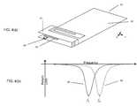
- FIG. 1( a )illustrates an exemplary isolated magnetic dipole (IMD) antenna.
- IMDisolated magnetic dipole
- FIG. 1( b )illustrates an exemplary radiation pattern associated with the antenna of FIG. 1( a ).
- FIG. 1( c )illustrates an exemplary frequency characteristic associated with the antenna of FIG. 1( a ).
- FIG. 2( a )illustrates an embodiment of an antenna according to the present invention.
- FIG. 2( b )illustrates an exemplary frequency characteristic associated with the antenna of FIG. 2( a ).
- FIG. 3( a )illustrates an embodiment of an antenna according to the present invention.
- FIG. 3( b )illustrates an exemplary radiation pattern associated with the antenna of FIG. 3( a ).
- FIG. 3( c )illustrates an embodiment of an antenna according to the present invention.
- FIG. 3( d )illustrates an exemplary radiation pattern associated with the antenna of FIG. 3( a ).
- FIG. 3( e )illustrates an exemplary frequency characteristic associated with the antennas of FIG. 3( a ) and FIG. 3( c ).
- FIG. 4( a )illustrates an exemplary IMD antenna comprising a parasitic element and an active tuning element.
- FIG. 4( b )illustrates an exemplary frequency characteristic associated with the antenna of FIG. 4( a ).
- FIG. 5( a )illustrates an embodiment of an antenna according to the present invention.
- FIG. 5( b )illustrates an exemplary frequency characteristic associated with the antenna of FIG. 5( a ).
- FIG. 6( a )illustrates an exemplary radiation pattern of an antenna according to the present invention.
- FIG. 6( b )illustrates an exemplary radiation pattern associated with an IMD antenna.
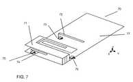
- FIG. 7illustrates an embodiment of an antenna according to the present invention.
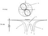
- FIG. 8( a )illustrates an exemplary radiation pattern associated with the antenna of FIG. 7 .
- FIG. 8( b )illustrates an exemplary frequency characteristic associated with the antenna of FIG. 7 .
- FIG. 9illustrates another embodiment of an antenna according to the present invention.
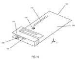
- FIG. 10illustrates another embodiment of an antenna according to the present invention.
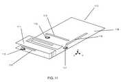
- FIG. 11illustrates another embodiment of an antenna according to the present invention.
- FIG. 12illustrates another embodiment of an antenna according to the present invention.
- FIG. 13illustrates another embodiment of an antenna according to the present invention.
- IMDIsolated Magnetic DipoleTM
- an antenna 10is shown to include an isolated magnetic dipole (IMD) element 11 that is situated on a ground plane 12 .
- the ground planemay be formed on a substrate such as a the printed circuit board (PCB) of a wireless device.
- PCBprinted circuit board
- FIG. 1( b )illustrates an exemplary radiation pattern 13 associated with the antenna system of FIG. 1( a ). The main lobes of the radiation pattern, as depicted in FIG.
- FIG. 1( b )are in the z direction.
- FIG. 1( c )illustrates the return loss as a function of frequency (hereinafter referred to as “frequency characteristic” 14 ) for the antenna of FIG. 1( a ) with a resonant frequency, f 0 . Further details regarding the operation and characteristics of such an antenna system may be found, for example, in the commonly owned U.S. patent application Ser. No. 11/675,557.
- FIG. 2( a )illustrates, an antenna 20 in accordance with an embodiment of the present invention.
- the antenna 20similar to that of FIG. 1( a ), includes a main IMD element 21 that is situated on a ground plane 24 .
- the antenna 20further comprises a parasitic element 22 and an active element 23 that are situated on a ground plane 24 , located to the side of the main IMD element 21 .
- the active tuning element 23is located on the parasitic element 22 or on a vertical connection thereof.
- the active tuning element 23can, for example, be any one or more of voltage controlled tunable capacitors, voltage controlled tunable phase shifters, FET's, switches, MEMs device, transistor, or circuit capable of exhibiting ON-OFF and/or actively controllable conductive/inductive characteristics. It should be further noted that coupling of the various active control elements to different antenna and/or parasitic elements, referenced throughout this specification, may be accomplished in different ways. For example, active elements may be deposited generally within the feed area of the antenna and/or parasitic elements by electrically coupling one end of the active element to the feed line, and coupling the other end to the ground portion. An exemplary frequency characteristic associated with the antenna 20 of FIG. 2( a ) is depicted in FIG. 2( b ).
- the active controlmay comprise a two state switch that either electrically connects (shorts) or disconnects (opens) the parasitic element to ground.
- FIG. 2( b )shows the frequency characteristic for the open and short states in dashed and solid lines, respectfully.
- the presence of the parasitic element 22with the active element 23 acting as a two state switch, results in a dual resonance frequency response.
- the typical single resonant frequency behavior 25 of an IMD antenna obtained in the open state with resonant frequency, f 0(shown with dashed lines)
- f 0shown with dashed lines
- a double resonant behavior 26shown with two peak frequencies f 1 and f 2 .
- the design of the parasitic element 22 and its distance from the main antenna element 21determine frequencies f 1 and f 2 .
- FIG. 3( a ) and FIG. 3( c )further illustrate an antenna 30 in accordance with an embodiment of the present invention. Similar to FIG. 2( a ), an main IMD element 31 is situated on a ground plane 36 . A parasitic element 32 and an active device 33 are also located to one side of the IMD element 31 . FIG. 3( a ) further illustrates the direction of current flow 35 (shown as solid arrow) in the main IMD element 31 , as well as the current flow direction 34 in the parasitic element 32 in the open state, while FIG. 3( c ) illustrates the direction of current flow 35 in the short state. As illustrated by the arrows in FIGS.
- FIG. 3( a ) and 3 ( c )the two resonances result from two different antenna modes.
- the antenna current 33 and the open parasitic element current 34are in phase.
- the antenna current 33 and the shorted parasitic element current 38are in opposite phases.
- FIG. 3( b )depicts a typical radiation pattern 37 associated with the antenna 30 when the parasitic element 32 is in open state, as illustrated in FIG. 3( a ).
- FIG. 3( d )illustrates an exemplary radiation pattern 39 associated with the antenna 30 when the parasitic element 32 is in short state, as illustrated in FIG.
- FIG. 3( e )further illustrates the frequency characteristics associated with either antenna configurations of FIG. 3( a ) (dashed) or FIG.
- FIG. 3( c )(solid), which illustrates a double resonant behavior 392 , as also depicted earlier in FIG. 2( b ).
- the possibility of operations such as beam switching and/or null-fillingmay be effected by controlling the current flow direction in the parasitic element 32 , with the aid of an active element 33 .
- FIGS. 2-3illustrate a parasitic element coupled to an active component.
- the active componenthas been described as a two-state switch in the above embodiment, it should be noted that in other embodiments the active component may comprise a voltage controlled tunable capacitor or other tunable component as referenced above. Where the parasitic is coupled to a voltage controlled tunable capacitor, or similar component, a reactance can be varied on the parasitic as would be understood by those having skill in the art. Accordingly, in certain embodiments, the active tuning element may be adapted to vary a reactance on the parasitic element for varying a current mode of the antenna.
- FIG. 4( a )illustrates another antenna configuration 40 , which includes an main IMD element 41 that is situated on a ground plane 42 .
- the antenna 40further includes a tuning parasitic element 43 and an active tuning device 44 , that are located on the ground plane 42 , below or within the volume of the main IMD element 41 .
- This antenna configurationas described in the co-pending U.S. patent application Ser. No. 11/847,207, provides a frequency tuning capability for the antenna 40 , wherein the antenna resonant frequency may be readily shifted along the frequency axis with the aid of the parasitic element 43 and the associated active tuning element 44 .
- An exemplary frequency characteristic illustrating this shifting capabilityis shown in FIG.
- FIG. 5( a )illustrates another embodiment of the present invention, where an antenna 50 is comprised of an main IMD element 51 , which is situated on a ground plane 56 , a first parasitic element 52 that is coupled with an active element 53 , and a second parasitic tuning element 54 that is coupled with a second active element 55 .
- the active elements 53 and 55may comprise two state switches that either electrically connect (short) or disconnect (open) the parasitic elements to the ground.
- the antenna 50can advantageously provide the frequency splitting and beam steering capabilities of the former with frequency shifting capability of the latter.
- FIG. 5( b )illustrates the frequency characteristic 59 associated with the exemplary embodiment of antenna 50 shown in FIG. 5( a ) in three different states.
- the first stateis illustrated as frequency characteristic 57 of a simple IMD, obtained when both parasitic elements 52 and 54 are open, leading to a resonant frequency f 0 .
- the second stateis illustrate as frequency shifted characteristic 58 associated with antenna 40 of FIG. 4( a ), obtained when parasitic element 54 is shorted to ground through switch 55 .
- the third stateis illustrated as a double resonant frequency characteristic 59 with resonant frequencies f 4 and f 0 , obtained when both parasitic elements 52 and 54 are shorted to ground through switches 53 and 55 .
- FIGS. 3( a )- 3 ( e )This combination enables two different modes of operation, as illustrated earlier in FIGS. 3( a )- 3 ( e ), but with a common frequency, f 0 .
- operationssuch as beam switching and/or null-filling may be readily effected using the exemplary configuration of FIG. 5 .
- FIG. 6( a )illustrates the radiation pattern at frequency f 0 associated with the antenna 50 of FIG. 5( a ) in the third state (all short), which exhibits a ninety-degree shift in direction as compared to the radiation pattern 61 of the antenna 50 of FIG.
- FIG. 7illustrates yet another antenna 70 in accordance with an embodiment of the present invention.
- the antenna 70comprises an IMD 71 that is situated on a ground plane 77 , a first parasitic element 72 that is coupled with a first active tuning element 73 , a second parasitic element 74 that is coupled with a second active tuning element 75 , and a third active element 76 that is coupled with the feed of the main IMD element 71 to provide active matching.
- the active elements 73 and 75can, for example, be any one or more of voltage controlled tunable capacitors, voltage controlled tunable phase shifters, FET's, switches, MEMs device, transistor, or circuit capable of exhibiting ON-OFF and/or actively controllable conductive/inductive characteristics.
- FIG. 1illustrates yet another antenna 70 in accordance with an embodiment of the present invention.
- the antenna 70comprises an IMD 71 that is situated on a ground plane 77 , a first parasitic element 72 that is coupled with a first active tuning element 73 , a
- FIG. 8( a )illustrates exemplary radiation patterns 80 that can be steered in different directions by utilizing the tuning capabilities of antenna 70 .
- FIG. 8( b )further illustrates the effects of tuning capabilities of antenna 70 on the frequency characteristic plot 83 .
- the simple IMD frequency characteristic 81which was previously transformed into a double resonant frequency characteristic 82 , may now be selectively shifted across the frequency axis, as depicted by the solid double resonant frequency characteristic plot 83 , with lower and upper resonant frequencies f L and f H , respectively.
- the radiation patterns at frequencies f L and f Hare represented in dashed lines in FIG. 8( a ).
- f L and f Hcan be adjusted in accordance with (f H ⁇ f 0 )/(f H ⁇ f L ), to any value between 0 and 1, therefore enabling all the intermediate radiation pattern.
- the return loss at f 0may be further improved by adjusting the third active matching element 76 .
- FIGS. 9 through 13illustrate embodiments of the present invention with different variations in the positioning, orientation, shape and number of parasitic and active tuning elements to facilitate beam switching, beam steering, null filling, and other beam control capabilities of the present invention.
- FIG. 9illustrates an antenna 90 that includes an IMD 91 , situated on a ground plane 99 , a first parasitic element 92 that is coupled with a first active tuning element 93 , a second parasitic element 94 that is coupled with a second active tuning element 95 , a third active tuning element 96 , and a third parasitic element 97 that is coupled with a corresponding active tuning element 98 .
- the third parasitic element 97 and the corresponding active tuning element 98provide a mechanism for effectuating beam steering or null filling at a different frequency. While FIG. 9 illustrates only two parasitic elements that are located to the side of the IMD 91 , it is understood that additional parasitic elements (and associated active tuning elements) may be added to effectuate a desired level of beam control and/or frequency shaping.
- FIG. 10illustrates an antenna in accordance with an embodiment of the present invention that is similar to the antenna configuration in FIG. 5( a ), except that the parasitic element 102 is rotated ninety degrees (as compared to the parasitic element 52 in FIG. 5( a )).
- the remaining antenna elementsspecifically, the IMD 101 , situated on a ground plane 106 , the parasitic element 104 and the associated tuning element 105 , remain in similar locations as their counterparts in FIG. 5( a ). While FIG. 10 illustrates a single parasitic element orientation with respect to IMD 101 , it is understood that orientation of the parasitic element may be readily adjusted to angles other than ninety degrees to effectuate the desired levels of beam control in other planes.
- FIG. 11provides another exemplary antenna in accordance with an embodiment of the present invention that is similar to that of FIG. 10 , except for the presence a third parasitic element 116 and the associated active tuning element 117 .
- the first parasitic element 112 and the third parasitic element 116are at an angle of ninety degrees with respect to each other.
- the remaining antenna components, namely the main IMD element 111 , the second parasitic element 114 and the associated active tuning device 115are situated in similar locations as their counterparts in FIG. 5( a ).
- This exemplary configurationillustrates that additional beam control capabilities may be obtained by the placement of multiple parasitic elements at specific orientations with respect to each other and/or the main IMD element enabling beam steering in any direction in space.
- FIG. 12illustrates yet another antenna in accordance with an embodiment of the present invention.
- This exemplary embodimentis similar to that of FIG. 5( a ), except for the placement of a first parasitic element 122 on the substrate of the antenna 120 .
- the parasitic element 122may be placed on the printed circuit board of the antenna.
- the remaining antenna elements, specifically, the IMD 121 , situated on a ground plane 126 , and the parasitic element 124 and the associated tuning element 125remain in similar locations as their counterparts in FIG. 5( a ).
- FIG. 13illustrates another antenna in accordance with an embodiment of the present invention.
- Antenna 130in this configuration, comprises an IMD 131 , situated on a ground plane 136 , a first parasitic element 132 coupled with a first active tuning element 133 , and a second parasitic element 134 that is coupled with a second active tuning element 135 .
- the unique feature of antenna 130is the presence of the first parasitic element 132 with multiple parasitic sections.
- the parasitic elementmay be designed to comprise two or more elements in order to effectuate a desired level of beam control and/or frequency shaping.
- FIGS. 9 through 13only provide exemplary modifications to the antenna configuration of FIG. 5( a ).
- Other modifications, including addition or elimination of parasitic and/or active tuning elements, or changes in orientation, shape, height, or position of such elementsmay be readily implemented to facilitate beam control and/or frequency shaping and are contemplated within the scope of the present invention.
Landscapes
- Engineering & Computer Science (AREA)
- Computer Networks & Wireless Communication (AREA)
- Variable-Direction Aerials And Aerial Arrays (AREA)
Abstract
Description
Claims (19)
Priority Applications (39)
| Application Number | Priority Date | Filing Date | Title |
|---|---|---|---|
| US13/029,564US8362962B2 (en) | 2008-03-05 | 2011-02-17 | Antenna and method for steering antenna beam direction |
| US13/548,895US8633863B2 (en) | 2008-03-05 | 2012-07-13 | Modal adaptive antenna using pilot signal in CDMA mobile communication system and related signal receiving method |
| US13/612,809US20130120200A1 (en) | 2011-02-17 | 2012-09-12 | Multi leveled active antenna configuration for multiband mimo lte system |
| US13/612,833US8604988B2 (en) | 2008-03-05 | 2012-09-13 | Multi-function array for access point and mobile wireless systems |
| US13/621,811US9559756B2 (en) | 2007-08-20 | 2012-09-17 | Antenna system optimized for SISO and MIMO operation |
| US13/622,356US8988289B2 (en) | 2008-03-05 | 2012-09-18 | Antenna system for interference supression |
| US13/674,078US8928540B2 (en) | 2007-08-20 | 2012-11-11 | Multi-antenna module containing active elements and control circuits for wireless systems |
| US13/674,081US8570231B2 (en) | 2007-08-20 | 2012-11-11 | Active front end module using a modal antenna approach for improved communication system performance |
| US13/674,117US9030361B2 (en) | 2008-03-05 | 2012-11-12 | Automatic signal, SAR, and HAC adjustment with modal antenna using proximity sensors or pre-defined conditions |
| US13/674,115US8928541B2 (en) | 2008-03-05 | 2012-11-12 | Active MIMO antenna configuration for maximizing throughput in mobile devices |
| US13/674,137US9160074B2 (en) | 2008-03-05 | 2012-11-12 | Modal antenna with correlation management for diversity applications |
| US13/674,100US9035836B2 (en) | 2007-08-20 | 2012-11-12 | Superimposed multimode antenna for enhanced system filtering |
| US13/674,112US8581789B2 (en) | 2007-08-20 | 2012-11-12 | Active self-reconfigurable multimode antenna system |
| US13/707,506US9590703B2 (en) | 2008-03-05 | 2012-12-06 | Modal cognitive diversity for mobile communication systems |
| US13/726,477US8648755B2 (en) | 2008-03-05 | 2012-12-24 | Antenna and method for steering antenna beam direction |
| US13/965,035US9431700B2 (en) | 2008-03-05 | 2013-08-12 | Modal antenna-integrated battery assembly |
| US14/040,531US9654230B2 (en) | 2007-08-20 | 2013-09-27 | Modal adaptive antenna for mobile applications |
| US14/071,560US9660348B2 (en) | 2008-03-05 | 2013-11-04 | Multi-function array for access point and mobile wireless systems |
| US14/094,778US9692122B2 (en) | 2008-03-05 | 2013-12-02 | Multi leveled active antenna configuration for multiband MIMO LTE system |
| US14/109,789US20140184445A1 (en) | 2008-03-05 | 2013-12-17 | Modal adaptive antenna using pilot signal in cdma mobile communication system and related signal receiving method |
| US14/144,461US9240634B2 (en) | 2007-08-17 | 2013-12-30 | Antenna and method for steering antenna beam direction |
| US14/219,002US9634404B1 (en) | 2008-03-05 | 2014-03-19 | Beam steering multiband architecture |
| US14/337,062US9065496B2 (en) | 2008-03-05 | 2014-07-21 | Method and system for switched combined diversity with a modal antenna |
| US14/617,612US9123986B2 (en) | 2008-03-05 | 2015-02-09 | Antenna system for interference supression |
| US14/690,323US9571176B2 (en) | 2008-03-05 | 2015-04-17 | Active MIMO antenna configuration for maximizing throughput in mobile devices |
| US14/691,536US9705197B2 (en) | 2007-08-20 | 2015-04-20 | Superimposed multimode antenna for enhanced system filtering |
| US14/930,651US10033097B2 (en) | 2008-03-05 | 2015-11-02 | Integrated antenna beam steering system |
| US14/965,881US9748637B2 (en) | 2008-03-05 | 2015-12-10 | Antenna and method for steering antenna beam direction for wifi applications |
| US15/085,335US9872327B2 (en) | 2008-03-05 | 2016-03-30 | Wireless communication system and related methods for use in a social network |
| US15/242,514US9917359B2 (en) | 2008-03-05 | 2016-08-20 | Repeater with multimode antenna |
| US15/261,840US9761940B2 (en) | 2008-03-05 | 2016-09-09 | Modal adaptive antenna using reference signal LTE protocol |
| US15/660,907US10056679B2 (en) | 2008-03-05 | 2017-07-26 | Antenna and method for steering antenna beam direction for WiFi applications |
| US15/671,506US10116050B2 (en) | 2008-03-05 | 2017-08-08 | Modal adaptive antenna using reference signal LTE protocol |
| US15/917,101US10263326B2 (en) | 2008-03-05 | 2018-03-09 | Repeater with multimode antenna |
| US16/048,987US10547102B2 (en) | 2008-03-05 | 2018-07-30 | Antenna and method for steering antenna beam direction for WiFi applications |
| US16/380,222US10770786B2 (en) | 2008-03-05 | 2019-04-10 | Repeater with multimode antenna |
| US16/751,903US11245179B2 (en) | 2008-03-05 | 2020-01-24 | Antenna and method for steering antenna beam direction for WiFi applications |
| US17/012,446US11942684B2 (en) | 2008-03-05 | 2020-09-04 | Repeater with multimode antenna |
| US18/348,968US20230352826A1 (en) | 2008-03-05 | 2023-07-07 | Repeater with Multimode Antenna |
Applications Claiming Priority (2)
| Application Number | Priority Date | Filing Date | Title |
|---|---|---|---|
| US12/043,090US7911402B2 (en) | 2008-03-05 | 2008-03-05 | Antenna and method for steering antenna beam direction |
| US13/029,564US8362962B2 (en) | 2008-03-05 | 2011-02-17 | Antenna and method for steering antenna beam direction |
Related Parent Applications (8)
| Application Number | Title | Priority Date | Filing Date |
|---|---|---|---|
| US12/043,090ContinuationUS7911402B2 (en) | 2007-08-17 | 2008-03-05 | Antenna and method for steering antenna beam direction |
| US201113227361AContinuation-In-Part | 2007-08-20 | 2011-09-07 | |
| US13/548,895Continuation-In-PartUS8633863B2 (en) | 2008-03-05 | 2012-07-13 | Modal adaptive antenna using pilot signal in CDMA mobile communication system and related signal receiving method |
| US13/621,811ContinuationUS9559756B2 (en) | 2007-08-20 | 2012-09-17 | Antenna system optimized for SISO and MIMO operation |
| US13/674,081ContinuationUS8570231B2 (en) | 2007-08-20 | 2012-11-11 | Active front end module using a modal antenna approach for improved communication system performance |
| US13/674,115ContinuationUS8928541B2 (en) | 2008-03-05 | 2012-11-12 | Active MIMO antenna configuration for maximizing throughput in mobile devices |
| US13/674,112ContinuationUS8581789B2 (en) | 2007-08-20 | 2012-11-12 | Active self-reconfigurable multimode antenna system |
| US13/674,100ContinuationUS9035836B2 (en) | 2007-08-20 | 2012-11-12 | Superimposed multimode antenna for enhanced system filtering |
Related Child Applications (16)
| Application Number | Title | Priority Date | Filing Date |
|---|---|---|---|
| US201113227361AContinuation-In-Part | 2007-08-20 | 2011-09-07 | |
| US13/548,895Continuation-In-PartUS8633863B2 (en) | 2008-03-05 | 2012-07-13 | Modal adaptive antenna using pilot signal in CDMA mobile communication system and related signal receiving method |
| US13/612,809Continuation-In-PartUS20130120200A1 (en) | 2008-03-05 | 2012-09-12 | Multi leveled active antenna configuration for multiband mimo lte system |
| US13/612,833Continuation-In-PartUS8604988B2 (en) | 2008-03-05 | 2012-09-13 | Multi-function array for access point and mobile wireless systems |
| US13/621,811Continuation-In-PartUS9559756B2 (en) | 2007-08-20 | 2012-09-17 | Antenna system optimized for SISO and MIMO operation |
| US13/622,356Continuation-In-PartUS8988289B2 (en) | 2008-03-05 | 2012-09-18 | Antenna system for interference supression |
| US13/674,078Continuation-In-PartUS8928540B2 (en) | 2007-08-20 | 2012-11-11 | Multi-antenna module containing active elements and control circuits for wireless systems |
| US13/674,081Continuation-In-PartUS8570231B2 (en) | 2007-08-20 | 2012-11-11 | Active front end module using a modal antenna approach for improved communication system performance |
| US13/674,137Continuation-In-PartUS9160074B2 (en) | 2008-03-05 | 2012-11-12 | Modal antenna with correlation management for diversity applications |
| US13/674,117Continuation-In-PartUS9030361B2 (en) | 2008-03-05 | 2012-11-12 | Automatic signal, SAR, and HAC adjustment with modal antenna using proximity sensors or pre-defined conditions |
| US13/674,112Continuation-In-PartUS8581789B2 (en) | 2007-08-20 | 2012-11-12 | Active self-reconfigurable multimode antenna system |
| US13/674,115Continuation-In-PartUS8928541B2 (en) | 2008-03-05 | 2012-11-12 | Active MIMO antenna configuration for maximizing throughput in mobile devices |
| US13/674,100Continuation-In-PartUS9035836B2 (en) | 2007-08-20 | 2012-11-12 | Superimposed multimode antenna for enhanced system filtering |
| US13/707,506Continuation-In-PartUS9590703B2 (en) | 2008-03-05 | 2012-12-06 | Modal cognitive diversity for mobile communication systems |
| US13/707,506ContinuationUS9590703B2 (en) | 2008-03-05 | 2012-12-06 | Modal cognitive diversity for mobile communication systems |
| US13/726,477ContinuationUS8648755B2 (en) | 2007-08-17 | 2012-12-24 | Antenna and method for steering antenna beam direction |
Publications (2)
| Publication Number | Publication Date |
|---|---|
| US20110254748A1 US20110254748A1 (en) | 2011-10-20 |
| US8362962B2true US8362962B2 (en) | 2013-01-29 |
Family
ID=41053072
Family Applications (4)
| Application Number | Title | Priority Date | Filing Date |
|---|---|---|---|
| US12/043,090Active2028-12-26US7911402B2 (en) | 2007-08-17 | 2008-03-05 | Antenna and method for steering antenna beam direction |
| US13/029,564ActiveUS8362962B2 (en) | 2007-08-17 | 2011-02-17 | Antenna and method for steering antenna beam direction |
| US13/726,477ActiveUS8648755B2 (en) | 2007-08-17 | 2012-12-24 | Antenna and method for steering antenna beam direction |
| US14/144,461ActiveUS9240634B2 (en) | 2007-08-17 | 2013-12-30 | Antenna and method for steering antenna beam direction |
Family Applications Before (1)
| Application Number | Title | Priority Date | Filing Date |
|---|---|---|---|
| US12/043,090Active2028-12-26US7911402B2 (en) | 2007-08-17 | 2008-03-05 | Antenna and method for steering antenna beam direction |
Family Applications After (2)
| Application Number | Title | Priority Date | Filing Date |
|---|---|---|---|
| US13/726,477ActiveUS8648755B2 (en) | 2007-08-17 | 2012-12-24 | Antenna and method for steering antenna beam direction |
| US14/144,461ActiveUS9240634B2 (en) | 2007-08-17 | 2013-12-30 | Antenna and method for steering antenna beam direction |
Country Status (3)
| Country | Link |
|---|---|
| US (4) | US7911402B2 (en) |
| CN (1) | CN102017297B (en) |
| WO (1) | WO2009111511A1 (en) |
Cited By (43)
| Publication number | Priority date | Publication date | Assignee | Title |
|---|---|---|---|---|
| US20130109333A1 (en)* | 2011-07-25 | 2013-05-02 | Sebastian Rowson | Method and system for switched combined diversity with a modal antenna |
| US20160218785A1 (en)* | 2015-01-26 | 2016-07-28 | Electronics And Telecommunications Research Institute | Smart antenna system and method for improving receiving performance thereof |
| WO2018102600A2 (en) | 2016-11-30 | 2018-06-07 | Ethertronics, Inc. | Active antenna steering for network security |
| US10084233B2 (en) | 2014-06-02 | 2018-09-25 | Ethertronics, Inc. | Modal antenna array for interference mitigation |
| US10109909B1 (en) | 2012-08-10 | 2018-10-23 | Ethertronics, Inc. | Antenna with proximity sensor function |
| US10122516B2 (en) | 2012-11-11 | 2018-11-06 | Ethertronics, Inc. | State prediction process and methodology |
| US10129929B2 (en) | 2011-07-24 | 2018-11-13 | Ethertronics, Inc. | Antennas configured for self-learning algorithms and related methods |
| US10171139B1 (en) | 2016-02-02 | 2019-01-01 | Ethertronics, Inc. | Inter-dwelling signal management using reconfigurable antennas |
| US10219208B1 (en) | 2014-08-07 | 2019-02-26 | Ethertronics, Inc. | Heterogeneous network optimization utilizing modal antenna techniques |
| US10224626B1 (en) | 2015-07-24 | 2019-03-05 | Ethertronics, Inc. | Co-located active steering antennas configured for band switching, impedance matching and unit selectivity |
| WO2019055492A1 (en) | 2017-09-13 | 2019-03-21 | Ethertronics, Inc. | Adaptive antenna for channel selection management in communication systems |
| US10313894B1 (en) | 2015-09-17 | 2019-06-04 | Ethertronics, Inc. | Beam steering techniques for external antenna configurations |
| US10355767B2 (en) | 2016-02-02 | 2019-07-16 | Ethertronics, Inc. | Network repeater system |
| US10355363B2 (en) | 2013-03-14 | 2019-07-16 | Ethertronics, Inc. | Antenna-like matching component |
| US10419749B2 (en) | 2017-06-20 | 2019-09-17 | Ethertronics, Inc. | Host-independent VHF-UHF active antenna system |
| US10439272B1 (en) | 2015-11-23 | 2019-10-08 | Ethertronics, Inc. | Beam steering system configured for multi-client network |
| US10476541B2 (en) | 2017-07-03 | 2019-11-12 | Ethertronics, Inc. | Efficient front end module |
| US10491282B2 (en) | 2012-12-17 | 2019-11-26 | Ethertronics, Inc. | Communication load balancing using distributed antenna beam steering techniques |
| US10491182B2 (en) | 2017-10-12 | 2019-11-26 | Ethertronics, Inc. | RF signal aggregator and antenna system implementing the same |
| US10511093B2 (en) | 2016-11-28 | 2019-12-17 | Ethertronics, Inc. | Active UHF/VHF antenna |
| US10536920B1 (en)* | 2015-01-09 | 2020-01-14 | Ethertronics, Inc. | System for location finding |
| US10535927B2 (en) | 2013-09-30 | 2020-01-14 | Ethertronics, Inc. | Antenna system for metallized devices |
| US10582456B2 (en) | 2017-06-07 | 2020-03-03 | Ethertronics, Inc. | Power control method for systems with altitude changing objects |
| US10587913B2 (en) | 2016-04-22 | 2020-03-10 | Ethertronics, Inc. | RF system for distribution of over the air content for in-building applications |
| US10587438B2 (en) | 2018-06-26 | 2020-03-10 | Avx Antenna, Inc. | Method and system for controlling a modal antenna |
| WO2020112270A1 (en) | 2018-11-30 | 2020-06-04 | Avx Antenna, Inc. D/B/A Ethertronics, Inc. | Operating a modal antenna system for point to multipoint communications |
| US10868371B2 (en) | 2017-03-24 | 2020-12-15 | Ethertronics, Inc. | Null steering antenna techniques for advanced communication systems |
| US10932284B2 (en) | 2016-02-02 | 2021-02-23 | Ethertronics, Inc. | Adaptive antenna for channel selection management in communications systems |
| US10942243B2 (en) | 2014-03-17 | 2021-03-09 | Ethertronics, Inc. | Method for finding signal direction using modal antenna |
| US10985462B2 (en) | 2016-11-30 | 2021-04-20 | Ethertronics, Inc. | Distributed control system for beam steering applications |
| US11189925B2 (en) | 2019-08-01 | 2021-11-30 | Avx Antenna, Inc. | Method and system for controlling a modal antenna |
| US11223404B2 (en) | 2019-06-24 | 2022-01-11 | Avx Antenna, Inc. | Beam forming and beam steering using antenna arrays |
| US11245206B2 (en) | 2019-03-21 | 2022-02-08 | Avx Antenna, Inc. | Multi-mode antenna system |
| US11283196B2 (en) | 2019-06-28 | 2022-03-22 | Avx Antenna, Inc. | Active antenna system for distributing over the air content |
| US11438036B2 (en) | 2019-11-14 | 2022-09-06 | KYOCERA AVX Components (San Diego), Inc. | Client grouping for point to multipoint communications |
| US11515914B2 (en) | 2020-09-25 | 2022-11-29 | KYOCERA AVX Components (San Diego), Inc. | Active antenna system for distributing over the air content |
| US11637372B2 (en) | 2019-01-31 | 2023-04-25 | KYOCERA AVX Components (San Diego), Inc. | Mobile computing device having a modal antenna |
| US11662758B2 (en) | 2019-03-15 | 2023-05-30 | KYOCERA AVX Components (San Diego), Inc. | Voltage regulator circuit for following a voltage source with offset control circuit |
| US11736154B2 (en) | 2020-04-30 | 2023-08-22 | KYOCERA AVX Components (San Diego), Inc. | Method and system for controlling an antenna array |
| US11742567B2 (en) | 2018-08-14 | 2023-08-29 | KYOCERA AVX Components (San Diego), Inc. | Method and system for controlling a modal antenna |
| US11824619B2 (en) | 2020-06-15 | 2023-11-21 | KYOCERA AVX Components (San Diego), Inc. | Antenna for cellular repeater systems |
| US11971308B2 (en) | 2020-08-26 | 2024-04-30 | KYOCERA AVX Components Corporation | Temperature sensor assembly facilitating beam steering in a temperature monitoring network |
| US12273153B2 (en) | 2020-03-12 | 2025-04-08 | KYOCERA AVX Components (San Diego), Inc. | System and method for surfacing channel quality indicator (CQI) data associated with a multi-mode antenna |
Families Citing this family (87)
| Publication number | Priority date | Publication date | Assignee | Title |
|---|---|---|---|---|
| US7911402B2 (en)* | 2008-03-05 | 2011-03-22 | Ethertronics, Inc. | Antenna and method for steering antenna beam direction |
| US20110032165A1 (en)* | 2009-08-05 | 2011-02-10 | Chew Chwee Heng | Antenna with multiple coupled regions |
| US9941588B2 (en) | 2007-08-20 | 2018-04-10 | Ethertronics, Inc. | Antenna with multiple coupled regions |
| US7777686B2 (en)* | 2008-03-31 | 2010-08-17 | Ethertronics, Inc. | Multi-layer isolated magnetic dipole antenna |
| US10033097B2 (en) | 2008-03-05 | 2018-07-24 | Ethertronics, Inc. | Integrated antenna beam steering system |
| US20140087781A1 (en) | 2012-09-18 | 2014-03-27 | Laurent Desclos | Wireless communication system & related methods for use in a social network |
| US8988289B2 (en)* | 2008-03-05 | 2015-03-24 | Ethertronics, Inc. | Antenna system for interference supression |
| US9748637B2 (en) | 2008-03-05 | 2017-08-29 | Ethertronics, Inc. | Antenna and method for steering antenna beam direction for wifi applications |
| US9761940B2 (en) | 2008-03-05 | 2017-09-12 | Ethertronics, Inc. | Modal adaptive antenna using reference signal LTE protocol |
| US9917359B2 (en) | 2008-03-05 | 2018-03-13 | Ethertronics, Inc. | Repeater with multimode antenna |
| US9160074B2 (en) | 2008-03-05 | 2015-10-13 | Ethertronics, Inc. | Modal antenna with correlation management for diversity applications |
| TWI423524B (en)* | 2009-05-20 | 2014-01-11 | Ind Tech Res Inst | Antenna structure with reconfigurable pattern and manufacturing method thereof |
| KR20110030113A (en) | 2009-09-17 | 2011-03-23 | 삼성전자주식회사 | Apparatus and method for adjusting a multiband antenna and its operating frequency in a wireless communication system |
| US8604980B2 (en) | 2009-12-22 | 2013-12-10 | Motorola Mobility Llc | Antenna system with non-resonating structure |
| US8842044B2 (en)* | 2010-08-27 | 2014-09-23 | Netgear, Inc. | Apparatus and method for operation of an antenna system enabling control of radiation characteristics |
| WO2012059302A2 (en) | 2010-10-12 | 2012-05-10 | Gn Resound A/S | An antenna device |
| US9014699B2 (en)* | 2011-06-14 | 2015-04-21 | Ethertronics, Inc. | Power management and control synchronization within in a wireless network using modal antennas and related methods |
| US9110160B2 (en) | 2011-07-24 | 2015-08-18 | Ethertronics, Inc. | Location finding using cellular modal antenna |
| US9608331B1 (en)* | 2011-09-08 | 2017-03-28 | Ethertronics, Inc. | SAR reduction architecture and technique for wireless devices |
| US9225069B2 (en) | 2011-10-18 | 2015-12-29 | California Institute Of Technology | Efficient active multi-drive radiator |
| US8995936B2 (en) | 2011-11-14 | 2015-03-31 | Ethertronics, Inc. | Communication system with band, mode, impedance and linearization self-adjustment |
| US20130187828A1 (en) | 2012-01-24 | 2013-07-25 | Ethertronics, Inc. | Tunable matching network for antenna systems |
| EP2621015B1 (en)* | 2012-01-27 | 2017-08-02 | BlackBerry Limited | Mobile wireless communications device with multiple-band antenna and related methods |
| WO2013123090A1 (en) | 2012-02-13 | 2013-08-22 | California Institute Of Technology | Sensing radiation metrics through mode-pickup sensors |
| TWI499128B (en)* | 2012-02-22 | 2015-09-01 | Arcadyan Technology Corp | Antenna for pcb |
| KR20130102171A (en)* | 2012-03-07 | 2013-09-17 | 주식회사 팬택 | Wireless terminal with indirect feeding antenna |
| TWI536901B (en)* | 2012-03-20 | 2016-06-01 | 深圳市華星光電技術有限公司 | Apparatus for controlling electric field distribution |
| US9112276B2 (en)* | 2012-03-21 | 2015-08-18 | Ethertronics, Inc. | Wideband antenna with low passive intermodulation attributes |
| CN102710275A (en)* | 2012-05-11 | 2012-10-03 | 中兴通讯股份有限公司 | Method for intelligently switching on/off mobile terminal antenna and corresponding mobile terminal |
| US9755305B2 (en)* | 2012-08-16 | 2017-09-05 | Ethertronics, Inc. | Active antenna adapted for impedance matching and band switching using a shared component |
| US20140057578A1 (en)* | 2012-08-24 | 2014-02-27 | Shih-Yi CHAN | Mobile Device and Antenna Structure Therein |
| EP2898567A4 (en)* | 2012-09-24 | 2016-05-25 | Qualcomm Inc | Tunable antenna structure |
| US9722298B2 (en) | 2012-10-25 | 2017-08-01 | Blackberry Limited | Mobile wireless communications device with multiple-band antenna and related methods |
| EP2917967A4 (en)* | 2012-11-12 | 2016-11-16 | Ethertronics Inc | MODAL ANTENNA COMPRISING CORRELATION MANAGEMENT FOR DIVERSITY APPLICATIONS |
| US10122402B2 (en)* | 2012-12-31 | 2018-11-06 | Futurewei Technologies, Inc. | Method and apparatus for a tunable antenna |
| USD733104S1 (en)* | 2013-01-18 | 2015-06-30 | Airgain, Inc. | Maximum beam antenna |
| US10720714B1 (en)* | 2013-03-04 | 2020-07-21 | Ethertronics, Inc. | Beam shaping techniques for wideband antenna |
| US10355358B2 (en)* | 2013-04-01 | 2019-07-16 | Ethertronics, Inc. | Reconfigurable multi-mode active antenna system |
| TWI497825B (en)* | 2013-04-19 | 2015-08-21 | Wistron Neweb Corp | Radio-frequency device and wireless communication device |
| TWI502803B (en)* | 2013-05-03 | 2015-10-01 | Acer Inc | Electronic apparatus |
| CN103367891A (en)* | 2013-05-10 | 2013-10-23 | 上海安费诺永亿通讯电子有限公司 | Reconfigurable low-SAR (specific absorption rate) value wireless terminal antenna and wireless terminal thereof |
| CN104183922A (en)* | 2013-05-28 | 2014-12-03 | 联想(北京)有限公司 | Novel antenna pattern including all frequency bands of cellular antenna and non-cellular antenna |
| EP3050156B1 (en)* | 2013-09-23 | 2022-04-20 | Cavendish Kinetics, Inc. | Techniques of tuning an antenna by weak coupling of a variable impedance component |
| WO2015074248A1 (en)* | 2013-11-22 | 2015-05-28 | 华为终端有限公司 | Antenna |
| US10084236B2 (en) | 2013-11-22 | 2018-09-25 | Huawei Device (Dongguan) Co., Ltd. | Tunable antenna and terminal |
| TWI511368B (en)* | 2013-12-18 | 2015-12-01 | Acer Inc | Mobile communication devic |
| KR102126263B1 (en)* | 2014-01-24 | 2020-06-24 | 삼성전자주식회사 | Antenna device and electronic device comprising the same |
| EP3120418B1 (en) | 2014-03-18 | 2020-09-16 | Ethertronics, Inc. | Modal antenna based communication network and methods for optimization thereof |
| US9693238B2 (en)* | 2014-04-21 | 2017-06-27 | Apple Inc. | Dynamic antenna tuning for multi-band multi-carrier wireless systems |
| TWI536660B (en) | 2014-04-23 | 2016-06-01 | 財團法人工業技術研究院 | Communication device and method for designing multi-antenna system thereof |
| USD798846S1 (en)* | 2014-11-17 | 2017-10-03 | Airgain Incorporated | Antenna assembly |
| US10128560B2 (en) | 2014-12-12 | 2018-11-13 | Ethertronics, Inc. | Hybrid antenna and integrated proximity sensor using a shared conductive structure |
| USD804458S1 (en)* | 2014-12-31 | 2017-12-05 | Airgain Incorporated | Antenna |
| USD804457S1 (en)* | 2014-12-31 | 2017-12-05 | Airgain Incorporated | Antenna assembly |
| US10056689B2 (en)* | 2015-06-09 | 2018-08-21 | Electronics And Telecommunications Research Institute | Electronically steerable parasitic radiator antenna and beam forming apparatus |
| US9792476B2 (en) | 2015-06-27 | 2017-10-17 | Meps Real-Time, Inc. | Medication tracking system and method using hybrid isolated magnetic dipole probe |
| USD813851S1 (en)* | 2015-07-30 | 2018-03-27 | Airgain Incorporated | Antenna |
| CN105826652B (en)* | 2015-11-02 | 2018-10-16 | 维沃移动通信有限公司 | A kind of antenna assembly and mobile terminal of mobile terminal |
| US10116052B2 (en)* | 2015-11-16 | 2018-10-30 | Semiconductor Components Industries, Llc | Tunable antenna for high-efficiency, wideband frequency coverage |
| US10122403B2 (en) | 2016-01-12 | 2018-11-06 | Fractus Antennas, S.L. | Wireless device |
| US10079922B2 (en) | 2016-03-11 | 2018-09-18 | Microsoft Technology Licensing, Llc | Conductive structural members acting as NFC antenna |
| CN107204512B (en)* | 2016-03-16 | 2019-12-06 | 北京小米移动软件有限公司 | Antenna for mobile terminal and mobile terminal |
| US10263319B2 (en)* | 2016-03-23 | 2019-04-16 | Mediatek Inc. | Antenna with swappable radiation direction and communication device thereof |
| US10129915B2 (en) | 2016-05-27 | 2018-11-13 | Semiconductor Components Industries, Llc | Efficient closed loop tuning using signal strength |
| TWI624997B (en)* | 2016-07-06 | 2018-05-21 | 廣達電腦股份有限公司 | Mobile device |
| JP6461061B2 (en)* | 2016-09-22 | 2019-01-30 | 株式会社ヨコオ | Antenna device |
| WO2018053849A1 (en)* | 2016-09-26 | 2018-03-29 | 深圳市大疆创新科技有限公司 | Antenna and unmanned aerial vehicle |
| CN106549229A (en)* | 2016-10-20 | 2017-03-29 | 惠州Tcl移动通信有限公司 | A kind of mobile terminal reduces the method and system of antenna tuning switching loss |
| TWI622228B (en)* | 2016-10-26 | 2018-04-21 | 泓博無線通訊技術有限公司 | Beam selection antenna system |
| TWI632735B (en)* | 2016-11-25 | 2018-08-11 | 泓博無線通訊技術有限公司 | Built-in beam selection antenna system |
| JP2019537391A (en) | 2016-12-12 | 2019-12-19 | スカイワークス ソリューションズ, インコーポレイテッドSkyworks Solutions, Inc. | Antenna system with reconfigurable frequency and polarization |
| US10965035B2 (en)* | 2017-05-18 | 2021-03-30 | Skyworks Solutions, Inc. | Reconfigurable antenna systems with ground tuning pads |
| CN107230839A (en)* | 2017-06-26 | 2017-10-03 | 广东欧珀移动通信有限公司 | Antenna tuning structure and mobile terminal |
| CN107453057A (en)* | 2017-07-31 | 2017-12-08 | 维沃移动通信有限公司 | A kind of beam direction adjustment circuit, electronic equipment and method |
| US11176765B2 (en) | 2017-08-21 | 2021-11-16 | Compx International Inc. | System and method for combined electronic inventory data and access control |
| WO2019136317A1 (en)* | 2018-01-05 | 2019-07-11 | Wispry, Inc. | Beam-steerable antenna devices, systems, and methods |
| CN115241645B (en)* | 2018-09-26 | 2025-02-11 | 华为技术有限公司 | Antennas and terminals |
| CN109830815B (en)* | 2018-12-24 | 2021-04-02 | 瑞声科技(南京)有限公司 | Antenna system and mobile terminal applying same |
| US11157789B2 (en) | 2019-02-18 | 2021-10-26 | Compx International Inc. | Medicinal dosage storage and method for combined electronic inventory data and access control |
| US11158938B2 (en) | 2019-05-01 | 2021-10-26 | Skyworks Solutions, Inc. | Reconfigurable antenna systems integrated with metal case |
| KR102780521B1 (en) | 2020-01-21 | 2025-03-12 | 삼성전자주식회사 | An antenna and an electronic device including the same |
| CN114946084B (en)* | 2020-01-24 | 2025-08-08 | 京瓷Avx元器件(圣地亚哥)有限公司 | Radio frequency (RF) amplifier circuit for an antenna system having a modal antenna |
| CN113497344B (en)* | 2020-04-07 | 2022-11-04 | 青岛海信移动通信技术股份有限公司 | Mobile terminal |
| US11569585B2 (en) | 2020-12-30 | 2023-01-31 | Industrial Technology Research Institute | Highly integrated pattern-variable multi-antenna array |
| WO2022147726A1 (en)* | 2021-01-07 | 2022-07-14 | 北京小米移动软件有限公司 | Beam scanning method and apparatus, communication device, and storage medium |
| US12407107B2 (en) | 2022-07-01 | 2025-09-02 | Skyworks Solutions, Inc. | Antenna systems with tunable frequency response circuits |
| WO2024065399A1 (en)* | 2022-09-29 | 2024-04-04 | 华为技术有限公司 | Antenna, control method and related device |
Citations (19)
| Publication number | Priority date | Publication date | Assignee | Title |
|---|---|---|---|---|
| US3971031A (en) | 1975-10-31 | 1976-07-20 | Burke Emmett F | Loaded quad antenna |
| US5235343A (en) | 1990-08-21 | 1993-08-10 | Societe D'etudes Et De Realisation De Protection Electronique Informatique Electronique | High frequency antenna with a variable directing radiation pattern |
| US5568155A (en) | 1992-12-07 | 1996-10-22 | Ntt Mobile Communications Network Incorporation | Antenna devices having double-resonance characteristics |
| US5598169A (en) | 1995-03-24 | 1997-01-28 | Lucent Technologies Inc. | Detector and modulator circuits for passive microwave links |
| US5874919A (en) | 1997-01-09 | 1999-02-23 | Harris Corporation | Stub-tuned, proximity-fed, stacked patch antenna |
| US6326921B1 (en) | 2000-03-14 | 2001-12-04 | Telefonaktiebolaget Lm Ericsson (Publ) | Low profile built-in multi-band antenna |
| US20040027286A1 (en) | 2001-06-26 | 2004-02-12 | Gregory Poilasne | Multi frequency magnetic dipole antenna structures and methods of reusing the volume of an antenna |
| US6765536B2 (en) | 2002-05-09 | 2004-07-20 | Motorola, Inc. | Antenna with variably tuned parasitic element |
| US20040227667A1 (en)* | 2003-05-12 | 2004-11-18 | Hrl Laboratories, Llc | Meta-element antenna and array |
| US20050192727A1 (en) | 1994-05-09 | 2005-09-01 | Automotive Technologies International Inc. | Sensor Assemblies |
| US20050275596A1 (en) | 2004-06-14 | 2005-12-15 | Nec Corporation | Antenna device and portable radio terminal |
| US20050285541A1 (en) | 2003-06-23 | 2005-12-29 | Lechevalier Robert E | Electron beam RF amplifier and emitter |
| US7081854B2 (en)* | 2002-05-02 | 2006-07-25 | Sony Ericsson Mobile Communications Ab | Printed built-in antenna for use in a portable electronic communication apparatus |
| US20060220966A1 (en) | 2005-03-29 | 2006-10-05 | Ethertronics | Antenna element-counterpoise arrangement in an antenna |
| US7132989B1 (en)* | 2005-05-04 | 2006-11-07 | Kyocera Wireless Corp. | Apparatus, system, and method for adjusting antenna characteristics using tunable parasitic elements |
| US20070069958A1 (en) | 2005-09-29 | 2007-03-29 | Sony Ericsson Mobile Communications Ab | Multi-band bent monopole antenna |
| US20070176824A1 (en) | 2002-09-30 | 2007-08-02 | Nanosys Inc. | Phased array systems and methods |
| US20080001829A1 (en) | 2006-06-30 | 2008-01-03 | Nokia Corporation | Mechanically tunable antenna for communication devices |
| US7903034B2 (en)* | 2005-09-19 | 2011-03-08 | Fractus, S.A. | Antenna set, portable wireless device, and use of a conductive element for tuning the ground-plane of the antenna set |
Family Cites Families (12)
| Publication number | Priority date | Publication date | Assignee | Title |
|---|---|---|---|---|
| NL61755C (en)* | 1938-04-28 | |||
| US2761134A (en)* | 1952-01-18 | 1956-08-28 | Bendix Aviat Corp | Means for operating antennas |
| US2938208A (en)* | 1955-01-05 | 1960-05-24 | Itt | Omnirange beacon antenna having rotating parasitic conductive elements |
| US5943016A (en)* | 1995-12-07 | 1999-08-24 | Atlantic Aerospace Electronics, Corp. | Tunable microstrip patch antenna and feed network therefor |
| US5777581A (en)* | 1995-12-07 | 1998-07-07 | Atlantic Aerospace Electronics Corporation | Tunable microstrip patch antennas |
| US6188373B1 (en)* | 1996-07-16 | 2001-02-13 | Metawave Communications Corporation | System and method for per beam elevation scanning |
| US6486844B2 (en)* | 2000-08-22 | 2002-11-26 | Skycross, Inc. | High gain, frequency tunable variable impedance transmission line loaded antenna having shaped top plates |
| US6903686B2 (en)* | 2002-12-17 | 2005-06-07 | Sony Ericsson Mobile Communications Ab | Multi-branch planar antennas having multiple resonant frequency bands and wireless terminals incorporating the same |
| WO2006015121A2 (en)* | 2004-07-29 | 2006-02-09 | Interdigital Technology Corporation | Multi-mode input impedance matching for smart antennas and associated methods |
| US7330156B2 (en)* | 2004-08-20 | 2008-02-12 | Nokia Corporation | Antenna isolation using grounded microwave elements |
| US7911402B2 (en)* | 2008-03-05 | 2011-03-22 | Ethertronics, Inc. | Antenna and method for steering antenna beam direction |
| US7830320B2 (en)* | 2007-08-20 | 2010-11-09 | Ethertronics, Inc. | Antenna with active elements |
- 2008
- 2008-03-05USUS12/043,090patent/US7911402B2/enactiveActive
- 2009
- 2009-03-03CNCN200980115992.XApatent/CN102017297B/enactiveActive
- 2009-03-03WOPCT/US2009/035933patent/WO2009111511A1/enactiveApplication Filing
- 2011
- 2011-02-17USUS13/029,564patent/US8362962B2/enactiveActive
- 2012
- 2012-12-24USUS13/726,477patent/US8648755B2/enactiveActive
- 2013
- 2013-12-30USUS14/144,461patent/US9240634B2/enactiveActive
Patent Citations (20)
| Publication number | Priority date | Publication date | Assignee | Title |
|---|---|---|---|---|
| US3971031A (en) | 1975-10-31 | 1976-07-20 | Burke Emmett F | Loaded quad antenna |
| US5235343A (en) | 1990-08-21 | 1993-08-10 | Societe D'etudes Et De Realisation De Protection Electronique Informatique Electronique | High frequency antenna with a variable directing radiation pattern |
| US5568155A (en) | 1992-12-07 | 1996-10-22 | Ntt Mobile Communications Network Incorporation | Antenna devices having double-resonance characteristics |
| US20050192727A1 (en) | 1994-05-09 | 2005-09-01 | Automotive Technologies International Inc. | Sensor Assemblies |
| US5598169A (en) | 1995-03-24 | 1997-01-28 | Lucent Technologies Inc. | Detector and modulator circuits for passive microwave links |
| US5874919A (en) | 1997-01-09 | 1999-02-23 | Harris Corporation | Stub-tuned, proximity-fed, stacked patch antenna |
| US6326921B1 (en) | 2000-03-14 | 2001-12-04 | Telefonaktiebolaget Lm Ericsson (Publ) | Low profile built-in multi-band antenna |
| US20040027286A1 (en) | 2001-06-26 | 2004-02-12 | Gregory Poilasne | Multi frequency magnetic dipole antenna structures and methods of reusing the volume of an antenna |
| US7081854B2 (en)* | 2002-05-02 | 2006-07-25 | Sony Ericsson Mobile Communications Ab | Printed built-in antenna for use in a portable electronic communication apparatus |
| US6765536B2 (en) | 2002-05-09 | 2004-07-20 | Motorola, Inc. | Antenna with variably tuned parasitic element |
| US20070176824A1 (en) | 2002-09-30 | 2007-08-02 | Nanosys Inc. | Phased array systems and methods |
| US20040227667A1 (en)* | 2003-05-12 | 2004-11-18 | Hrl Laboratories, Llc | Meta-element antenna and array |
| US7068234B2 (en) | 2003-05-12 | 2006-06-27 | Hrl Laboratories, Llc | Meta-element antenna and array |
| US20050285541A1 (en) | 2003-06-23 | 2005-12-29 | Lechevalier Robert E | Electron beam RF amplifier and emitter |
| US20050275596A1 (en) | 2004-06-14 | 2005-12-15 | Nec Corporation | Antenna device and portable radio terminal |
| US20060220966A1 (en) | 2005-03-29 | 2006-10-05 | Ethertronics | Antenna element-counterpoise arrangement in an antenna |
| US7132989B1 (en)* | 2005-05-04 | 2006-11-07 | Kyocera Wireless Corp. | Apparatus, system, and method for adjusting antenna characteristics using tunable parasitic elements |
| US7903034B2 (en)* | 2005-09-19 | 2011-03-08 | Fractus, S.A. | Antenna set, portable wireless device, and use of a conductive element for tuning the ground-plane of the antenna set |
| US20070069958A1 (en) | 2005-09-29 | 2007-03-29 | Sony Ericsson Mobile Communications Ab | Multi-band bent monopole antenna |
| US20080001829A1 (en) | 2006-06-30 | 2008-01-03 | Nokia Corporation | Mechanically tunable antenna for communication devices |
Cited By (92)
| Publication number | Priority date | Publication date | Assignee | Title |
|---|---|---|---|---|
| US10362636B2 (en) | 2011-07-24 | 2019-07-23 | Ethertronics, Inc. | Antennas configured for self-learning algorithms and related methods |
| US10129929B2 (en) | 2011-07-24 | 2018-11-13 | Ethertronics, Inc. | Antennas configured for self-learning algorithms and related methods |
| US20130109333A1 (en)* | 2011-07-25 | 2013-05-02 | Sebastian Rowson | Method and system for switched combined diversity with a modal antenna |
| US10109909B1 (en) | 2012-08-10 | 2018-10-23 | Ethertronics, Inc. | Antenna with proximity sensor function |
| US11509441B2 (en) | 2012-11-11 | 2022-11-22 | KYOCERA AVX Components (San Diego), Inc. | State prediction process and methodology |
| US10122516B2 (en) | 2012-11-11 | 2018-11-06 | Ethertronics, Inc. | State prediction process and methodology |
| US10924247B2 (en) | 2012-11-11 | 2021-02-16 | Ethertronics, Inc. | State prediction process and methodology |
| US10374779B2 (en) | 2012-11-11 | 2019-08-06 | Ethertronics, Inc. | State prediction process and methodology |
| US10491282B2 (en) | 2012-12-17 | 2019-11-26 | Ethertronics, Inc. | Communication load balancing using distributed antenna beam steering techniques |
| US11700042B2 (en) | 2012-12-17 | 2023-07-11 | KYOCERA AVX Components (San Diego), Inc. | Communication load balancing using distributed antenna beam steering techniques |
| US11171422B2 (en) | 2013-03-14 | 2021-11-09 | Ethertronics, Inc. | Antenna-like matching component |
| US10355363B2 (en) | 2013-03-14 | 2019-07-16 | Ethertronics, Inc. | Antenna-like matching component |
| US11710903B2 (en) | 2013-03-14 | 2023-07-25 | KYOCERA AVX Components (San Diego), Inc. | Antenna-like matching component |
| US10535927B2 (en) | 2013-09-30 | 2020-01-14 | Ethertronics, Inc. | Antenna system for metallized devices |
| US11714155B2 (en) | 2014-03-17 | 2023-08-01 | KYOCERA AVX Components (San Diego), Inc. | Method for finding signal direction using modal antenna |
| US12085656B2 (en) | 2014-03-17 | 2024-09-10 | KYOCERA AVX Components (San Diego), Inc. | Method for finding signal direction using modal antenna |
| US10942243B2 (en) | 2014-03-17 | 2021-03-09 | Ethertronics, Inc. | Method for finding signal direction using modal antenna |
| US10084233B2 (en) | 2014-06-02 | 2018-09-25 | Ethertronics, Inc. | Modal antenna array for interference mitigation |
| US10505274B2 (en) | 2014-06-02 | 2019-12-10 | Ethertronics, Inc. | Modal antenna array for interference mitigation |
| US10631239B2 (en) | 2014-08-07 | 2020-04-21 | Ethertronics, Inc. | Heterogeneous network optimization utilizing modal antenna techniques |
| US11011838B2 (en) | 2014-08-07 | 2021-05-18 | Ethertronics, Inc. | Heterogeneous network optimization utilizing modal antenna techniques |
| US11888235B2 (en) | 2014-08-07 | 2024-01-30 | KYOCERA AVX Components (San Diego), Inc. | Heterogeneous network optimization utilizing modal antenna techniques |
| US12347936B2 (en) | 2014-08-07 | 2025-07-01 | KYOCERA AVX Components (San Diego), Inc. | Heterogeneous network optimization utilizing modal antenna techniques |
| US10219208B1 (en) | 2014-08-07 | 2019-02-26 | Ethertronics, Inc. | Heterogeneous network optimization utilizing modal antenna techniques |
| US10536920B1 (en)* | 2015-01-09 | 2020-01-14 | Ethertronics, Inc. | System for location finding |
| US9755321B2 (en)* | 2015-01-26 | 2017-09-05 | Electronics And Telecommunications Research Institute | Smart antenna system and method for improving receiving performance thereof |
| US20160218785A1 (en)* | 2015-01-26 | 2016-07-28 | Electronics And Telecommunications Research Institute | Smart antenna system and method for improving receiving performance thereof |
| US10418704B2 (en) | 2015-07-24 | 2019-09-17 | Ethertronics, Inc. | Co-located active steering antennas configured for band switching, impedance matching and unit selectivity |
| US10224626B1 (en) | 2015-07-24 | 2019-03-05 | Ethertronics, Inc. | Co-located active steering antennas configured for band switching, impedance matching and unit selectivity |
| US11134394B2 (en) | 2015-09-17 | 2021-09-28 | Ethertronics, Inc. | Beam steering techniques for external antenna configurations |
| US10313894B1 (en) | 2015-09-17 | 2019-06-04 | Ethertronics, Inc. | Beam steering techniques for external antenna configurations |
| US11108136B2 (en) | 2015-11-23 | 2021-08-31 | Ethertronics, Inc. | Beam steering system configured for multi-client network |
| US10439272B1 (en) | 2015-11-23 | 2019-10-08 | Ethertronics, Inc. | Beam steering system configured for multi-client network |
| US11665725B2 (en) | 2016-02-02 | 2023-05-30 | KYOCERA AVX Components (San Diego), Inc. | Adaptive antenna for channel selection management in communications systems |
| US11342984B2 (en) | 2016-02-02 | 2022-05-24 | KYOCERA AVX Components (San Diego), Inc. | Wireless device system |
| US11283493B2 (en) | 2016-02-02 | 2022-03-22 | Ethertronics, Inc | Inter-dwelling signal management using reconfigurable antennas |
| US10833754B2 (en) | 2016-02-02 | 2020-11-10 | Ethertronics, Inc. | Network repeater system |
| US10355767B2 (en) | 2016-02-02 | 2019-07-16 | Ethertronics, Inc. | Network repeater system |
| US10171139B1 (en) | 2016-02-02 | 2019-01-01 | Ethertronics, Inc. | Inter-dwelling signal management using reconfigurable antennas |
| US10932284B2 (en) | 2016-02-02 | 2021-02-23 | Ethertronics, Inc. | Adaptive antenna for channel selection management in communications systems |
| US11489566B2 (en) | 2016-02-02 | 2022-11-01 | KYOCERA AVX Components (San Diego), Inc. | Inter-dwelling signal management using reconfigurable antennas |
| US12127230B2 (en) | 2016-02-02 | 2024-10-22 | KYOCERA AVX Components (San Diego), Inc. | Adaptive antenna for channel selection management in communications systems |
| US10574310B2 (en) | 2016-02-02 | 2020-02-25 | Ethertronics, Inc. | Inter-dwelling signal management using reconfigurable antennas |
| US10574336B2 (en) | 2016-02-02 | 2020-02-25 | Ethertronics, Inc. | Network repeater system |
| US11064246B2 (en) | 2016-04-22 | 2021-07-13 | Ethertronics, Inc. | RF system for distribution of over the air content for in-building applications |
| US10587913B2 (en) | 2016-04-22 | 2020-03-10 | Ethertronics, Inc. | RF system for distribution of over the air content for in-building applications |
| US12058405B2 (en) | 2016-04-22 | 2024-08-06 | Kyocera AVX Compoments (San Diego), Inc. | RF system for distribution of over the air content for in-building applications |
| US10511093B2 (en) | 2016-11-28 | 2019-12-17 | Ethertronics, Inc. | Active UHF/VHF antenna |
| US11380992B2 (en) | 2016-11-28 | 2022-07-05 | KYOCERA AVX Components (San Diego), Inc. | Active UHF/VHF antenna |
| US10985462B2 (en) | 2016-11-30 | 2021-04-20 | Ethertronics, Inc. | Distributed control system for beam steering applications |
| WO2018102600A2 (en) | 2016-11-30 | 2018-06-07 | Ethertronics, Inc. | Active antenna steering for network security |
| US11038270B2 (en) | 2016-11-30 | 2021-06-15 | Ethertronics, Inc. | Active antenna steering for network security |
| US20230061805A1 (en)* | 2016-11-30 | 2023-03-02 | KYOCERA AVX Components (San Diego), Inc. | Distributed Control System for Beam Steering Applications |
| US11462830B2 (en) | 2016-11-30 | 2022-10-04 | KYOCERA AVX Components (San Diego), Inc. | Distributed control system for beam steering applications |
| US10476155B2 (en) | 2016-11-30 | 2019-11-12 | Ethertronics, Inc. | Active antenna steering for network security |
| US10868371B2 (en) | 2017-03-24 | 2020-12-15 | Ethertronics, Inc. | Null steering antenna techniques for advanced communication systems |
| US12199347B2 (en) | 2017-03-24 | 2025-01-14 | KYOCERA AVX Components (San Diego), Inc. | Null steering antenna techniques for advanced communication systems |
| US10582456B2 (en) | 2017-06-07 | 2020-03-03 | Ethertronics, Inc. | Power control method for systems with altitude changing objects |
| US11026188B2 (en) | 2017-06-07 | 2021-06-01 | Ethertronics, Inc. | Power control method for systems with altitude changing objects |
| US10419749B2 (en) | 2017-06-20 | 2019-09-17 | Ethertronics, Inc. | Host-independent VHF-UHF active antenna system |
| US11284064B2 (en) | 2017-06-20 | 2022-03-22 | Ethertronics, Inc. | Host-independent VHF-UHF active antenna system |
| US10764573B2 (en) | 2017-06-20 | 2020-09-01 | Ethertronics, Inc. | Host-independent VHF-UHF active antenna system |
| US11128332B2 (en) | 2017-07-03 | 2021-09-21 | Ethertronics, Inc. | Efficient front end module |
| US10476541B2 (en) | 2017-07-03 | 2019-11-12 | Ethertronics, Inc. | Efficient front end module |
| WO2019055492A1 (en) | 2017-09-13 | 2019-03-21 | Ethertronics, Inc. | Adaptive antenna for channel selection management in communication systems |
| US10491182B2 (en) | 2017-10-12 | 2019-11-26 | Ethertronics, Inc. | RF signal aggregator and antenna system implementing the same |
| US11671069B2 (en) | 2017-10-12 | 2023-06-06 | KYOCERA AVX Components (San Diego), Inc. | RF signal aggregator and antenna system implementing the same |
| US10587438B2 (en) | 2018-06-26 | 2020-03-10 | Avx Antenna, Inc. | Method and system for controlling a modal antenna |
| US12266850B2 (en) | 2018-08-14 | 2025-04-01 | KYOCERA AVX Components (San Diego), Inc. | Method and system for controlling a modal antenna |
| US11742567B2 (en) | 2018-08-14 | 2023-08-29 | KYOCERA AVX Components (San Diego), Inc. | Method and system for controlling a modal antenna |
| WO2020112270A1 (en) | 2018-11-30 | 2020-06-04 | Avx Antenna, Inc. D/B/A Ethertronics, Inc. | Operating a modal antenna system for point to multipoint communications |
| US11764490B2 (en) | 2018-11-30 | 2023-09-19 | KYOCERA AVX Components (San Diego), Inc. | Operating a modal antenna system for point to multipoint communications |
| US11387577B2 (en) | 2018-11-30 | 2022-07-12 | KYOCERA AVX Components (San Diego), Inc. | Channel quality measurement using beam steering in wireless communication networks |
| US11637372B2 (en) | 2019-01-31 | 2023-04-25 | KYOCERA AVX Components (San Diego), Inc. | Mobile computing device having a modal antenna |
| US11662758B2 (en) | 2019-03-15 | 2023-05-30 | KYOCERA AVX Components (San Diego), Inc. | Voltage regulator circuit for following a voltage source with offset control circuit |
| US11245206B2 (en) | 2019-03-21 | 2022-02-08 | Avx Antenna, Inc. | Multi-mode antenna system |
| US11595096B2 (en) | 2019-06-24 | 2023-02-28 | KYOCERA AVX Components (San Diego), Inc. | Beam forming and beam steering using antenna arrays |
| US11916632B2 (en) | 2019-06-24 | 2024-02-27 | KYOCERA AVX Components (San Diego), Inc. | Beam forming and beam steering using antenna arrays |
| US12289152B2 (en) | 2019-06-24 | 2025-04-29 | KYOCERA AVX Components (San Diego), Inc. | Beam forming and beam steering using antenna arrays |
| US11223404B2 (en) | 2019-06-24 | 2022-01-11 | Avx Antenna, Inc. | Beam forming and beam steering using antenna arrays |
| US11283196B2 (en) | 2019-06-28 | 2022-03-22 | Avx Antenna, Inc. | Active antenna system for distributing over the air content |
| US11682836B2 (en) | 2019-08-01 | 2023-06-20 | KYOCERA AVX Components (San Diego), Inc. | Method and system for controlling a modal antenna |
| US11189925B2 (en) | 2019-08-01 | 2021-11-30 | Avx Antenna, Inc. | Method and system for controlling a modal antenna |
| US11791869B2 (en) | 2019-11-14 | 2023-10-17 | KYOCERA AVX Components (San Diego), Inc. | Client grouping for point to multipoint communications |
| US11438036B2 (en) | 2019-11-14 | 2022-09-06 | KYOCERA AVX Components (San Diego), Inc. | Client grouping for point to multipoint communications |
| US12160291B2 (en) | 2019-11-14 | 2024-12-03 | KYOCERA AVX Components (San Diego), Inc. | Client grouping for point to multipoint communications |
| US12273153B2 (en) | 2020-03-12 | 2025-04-08 | KYOCERA AVX Components (San Diego), Inc. | System and method for surfacing channel quality indicator (CQI) data associated with a multi-mode antenna |
| US11736154B2 (en) | 2020-04-30 | 2023-08-22 | KYOCERA AVX Components (San Diego), Inc. | Method and system for controlling an antenna array |
| US12081309B2 (en) | 2020-06-15 | 2024-09-03 | KYOCERA AVX Components (San Diego), Inc. | Antenna for cellular repeater systems |
| US11824619B2 (en) | 2020-06-15 | 2023-11-21 | KYOCERA AVX Components (San Diego), Inc. | Antenna for cellular repeater systems |
| US11971308B2 (en) | 2020-08-26 | 2024-04-30 | KYOCERA AVX Components Corporation | Temperature sensor assembly facilitating beam steering in a temperature monitoring network |
| US11515914B2 (en) | 2020-09-25 | 2022-11-29 | KYOCERA AVX Components (San Diego), Inc. | Active antenna system for distributing over the air content |
Also Published As
| Publication number | Publication date |
|---|---|
| WO2009111511A1 (en) | 2009-09-11 |
| US8648755B2 (en) | 2014-02-11 |
| CN102017297B (en) | 2016-01-27 |
| US20140218245A1 (en) | 2014-08-07 |
| US7911402B2 (en) | 2011-03-22 |
| CN102017297A (en) | 2011-04-13 |
| US20090224991A1 (en) | 2009-09-10 |
| US20110254748A1 (en) | 2011-10-20 |
| US9240634B2 (en) | 2016-01-19 |
| US20130113667A1 (en) | 2013-05-09 |
Similar Documents
| Publication | Publication Date | Title |
|---|---|---|
| US8362962B2 (en) | Antenna and method for steering antenna beam direction | |
| US11245179B2 (en) | Antenna and method for steering antenna beam direction for WiFi applications | |
| US8077116B2 (en) | Antenna with active elements | |
| EP3105820B1 (en) | A reconfigurable radio frequency aperture | |
| US6480158B2 (en) | Narrow-band, crossed-element, offset-tuned dual band, dual mode meander line loaded antenna | |
| US8421702B2 (en) | Multi-layer reactively loaded isolated magnetic dipole antenna | |
| US9941584B2 (en) | Reducing antenna array feed modules through controlled mutual coupling of a pixelated EM surface | |
| JP2001284954A (en) | Surface mount antenna, frequency control and setting method for dual resonance therefor and communication equipment provided with surface mount antenna | |
| KR102683311B1 (en) | Isolated magnetic dipole antennas having angled edges for improved tuning | |
| US6469675B1 (en) | High gain, frequency tunable variable impedance transmission line loaded antenna with radiating and tuning wing | |
| WO2001093372A1 (en) | Narrow-band, crossed-element, offset-tuned dual band, dual mode meander line loaded antenna | |
| US7420518B2 (en) | Planar antenna with matched impedance and/or polarization | |
| Morrow et al. | Microstrip antennas utilising MEMS for reconfigurable polarisation states |
Legal Events
| Date | Code | Title | Description |
|---|---|---|---|
| STCF | Information on status: patent grant | Free format text:PATENTED CASE | |
| AS | Assignment | Owner name:SILICON VALLY BANK, CALIFORNIA Free format text:SECURITY AGREEMENT;ASSIGNOR:ETHERTRONICS, INC.;REEL/FRAME:030112/0223 Effective date:20130329 Owner name:GOLD HILL CAPITAL 2008, LP, CALIFORNIA Free format text:SECURITY AGREEMENT;ASSIGNOR:ETHERTRONICS, INC.;REEL/FRAME:030112/0223 Effective date:20130329 | |
| FPAY | Fee payment | Year of fee payment:4 | |
| AS | Assignment | Owner name:ETHERTRONICS, INC., CALIFORNIA Free format text:ASSIGNMENT OF ASSIGNORS INTEREST;ASSIGNORS:SHAMBLIN, JEFFREY;DESCLOS, LAURENT;ROWSON, SEBASTIAN;SIGNING DATES FROM 20121218 TO 20121226;REEL/FRAME:039498/0174 | |
| AS | Assignment | Owner name:NH EXPANSION CREDIT FUND HOLDINGS LP, NEW YORK Free format text:SECURITY INTEREST;ASSIGNOR:ETHERTRONICS, INC.;REEL/FRAME:040464/0245 Effective date:20161013 | |
| AS | Assignment | Owner name:ETHERTRONICS, INC., CALIFORNIA Free format text:RELEASE BY SECURED PARTY;ASSIGNORS:SILICON VALLEY BANK;GOLD HILL CAPITAL 2008, LP;REEL/FRAME:040331/0919 Effective date:20161101 | |
| AS | Assignment | Owner name:ETHERTRONICS, INC., CALIFORNIA Free format text:RELEASE BY SECURED PARTY;ASSIGNOR:NH EXPANSION CREDIT FUND HOLDINGS LP;REEL/FRAME:045210/0725 Effective date:20180131 | |
| FEPP | Fee payment procedure | Free format text:ENTITY STATUS SET TO UNDISCOUNTED (ORIGINAL EVENT CODE: BIG.) | |
| MAFP | Maintenance fee payment | Free format text:PAYMENT OF MAINTENANCE FEE, 8TH YEAR, LARGE ENTITY (ORIGINAL EVENT CODE: M1552); ENTITY STATUS OF PATENT OWNER: LARGE ENTITY Year of fee payment:8 | |
| AS | Assignment | Owner name:KYOCERA AVX COMPONENTS (SAN DIEGO), INC., CALIFORNIA Free format text:CHANGE OF NAME;ASSIGNOR:AVX ANTENNA, INC.;REEL/FRAME:063543/0302 Effective date:20211001 | |
| AS | Assignment | Owner name:AVX ANTENNA, INC., CALIFORNIA Free format text:CHANGE OF NAME;ASSIGNOR:ETHERTRONICS, INC.;REEL/FRAME:063549/0336 Effective date:20180206 | |
| MAFP | Maintenance fee payment | Free format text:PAYMENT OF MAINTENANCE FEE, 12TH YEAR, LARGE ENTITY (ORIGINAL EVENT CODE: M1553); ENTITY STATUS OF PATENT OWNER: LARGE ENTITY Year of fee payment:12 |