US8362838B2 - Multi-stage amplifier with multiple sets of fixed and variable voltage rails - Google Patents
Multi-stage amplifier with multiple sets of fixed and variable voltage railsDownload PDFInfo
- Publication number
- US8362838B2 US8362838B2US11/694,348US69434807AUS8362838B2US 8362838 B2US8362838 B2US 8362838B2US 69434807 AUS69434807 AUS 69434807AUS 8362838 B2US8362838 B2US 8362838B2
- Authority
- US
- United States
- Prior art keywords
- voltage
- stage
- input signal
- amplification stage
- power supply
- Prior art date
- Legal status (The legal status is an assumption and is not a legal conclusion. Google has not performed a legal analysis and makes no representation as to the accuracy of the status listed.)
- Active, expires
Links
Images


Classifications
- H—ELECTRICITY
- H03—ELECTRONIC CIRCUITRY
- H03F—AMPLIFIERS
- H03F1/00—Details of amplifiers with only discharge tubes, only semiconductor devices or only unspecified devices as amplifying elements
- H03F1/02—Modifications of amplifiers to raise the efficiency, e.g. gliding Class A stages, use of an auxiliary oscillation
- H03F1/0205—Modifications of amplifiers to raise the efficiency, e.g. gliding Class A stages, use of an auxiliary oscillation in transistor amplifiers
- H03F1/0211—Modifications of amplifiers to raise the efficiency, e.g. gliding Class A stages, use of an auxiliary oscillation in transistor amplifiers with control of the supply voltage or current
- H03F1/0216—Continuous control
- H03F1/0222—Continuous control by using a signal derived from the input signal
- H03F1/0227—Continuous control by using a signal derived from the input signal using supply converters
- H—ELECTRICITY
- H03—ELECTRONIC CIRCUITRY
- H03F—AMPLIFIERS
- H03F3/00—Amplifiers with only discharge tubes or only semiconductor devices as amplifying elements
- H03F3/181—Low-frequency amplifiers, e.g. audio preamplifiers
- H03F3/183—Low-frequency amplifiers, e.g. audio preamplifiers with semiconductor devices only
- H03F3/187—Low-frequency amplifiers, e.g. audio preamplifiers with semiconductor devices only in integrated circuits
- H—ELECTRICITY
- H03—ELECTRONIC CIRCUITRY
- H03F—AMPLIFIERS
- H03F3/00—Amplifiers with only discharge tubes or only semiconductor devices as amplifying elements
- H03F3/45—Differential amplifiers
- H03F3/45071—Differential amplifiers with semiconductor devices only
- H03F3/45076—Differential amplifiers with semiconductor devices only characterised by the way of implementation of the active amplifying circuit in the differential amplifier
- H03F3/45179—Differential amplifiers with semiconductor devices only characterised by the way of implementation of the active amplifying circuit in the differential amplifier using MOSFET transistors as the active amplifying circuit
- H03F3/45183—Long tailed pairs
- H—ELECTRICITY
- H03—ELECTRONIC CIRCUITRY
- H03F—AMPLIFIERS
- H03F3/00—Amplifiers with only discharge tubes or only semiconductor devices as amplifying elements
- H03F3/45—Differential amplifiers
- H03F3/45071—Differential amplifiers with semiconductor devices only
- H03F3/45076—Differential amplifiers with semiconductor devices only characterised by the way of implementation of the active amplifying circuit in the differential amplifier
- H03F3/45475—Differential amplifiers with semiconductor devices only characterised by the way of implementation of the active amplifying circuit in the differential amplifier using IC blocks as the active amplifying circuit
- H—ELECTRICITY
- H03—ELECTRONIC CIRCUITRY
- H03F—AMPLIFIERS
- H03F2200/00—Indexing scheme relating to amplifiers
- H03F2200/03—Indexing scheme relating to amplifiers the amplifier being designed for audio applications
- H—ELECTRICITY
- H03—ELECTRONIC CIRCUITRY
- H03F—AMPLIFIERS
- H03F2200/00—Indexing scheme relating to amplifiers
- H03F2200/351—Pulse width modulation being used in an amplifying circuit
- H—ELECTRICITY
- H03—ELECTRONIC CIRCUITRY
- H03F—AMPLIFIERS
- H03F2200/00—Indexing scheme relating to amplifiers
- H03F2200/405—Indexing scheme relating to amplifiers the output amplifying stage of an amplifier comprising more than three power stages
- H—ELECTRICITY
- H03—ELECTRONIC CIRCUITRY
- H03F—AMPLIFIERS
- H03F2200/00—Indexing scheme relating to amplifiers
- H03F2200/408—Indexing scheme relating to amplifiers the output amplifying stage of an amplifier comprising three power stages
- H—ELECTRICITY
- H03—ELECTRONIC CIRCUITRY
- H03F—AMPLIFIERS
- H03F2200/00—Indexing scheme relating to amplifiers
- H03F2200/504—Indexing scheme relating to amplifiers the supply voltage or current being continuously controlled by a controlling signal, e.g. the controlling signal of a transistor implemented as variable resistor in a supply path for, an IC-block showed amplifier
- H—ELECTRICITY
- H03—ELECTRONIC CIRCUITRY
- H03F—AMPLIFIERS
- H03F2200/00—Indexing scheme relating to amplifiers
- H03F2200/516—Some amplifier stages of an amplifier use supply voltages of different value
- H—ELECTRICITY
- H03—ELECTRONIC CIRCUITRY
- H03F—AMPLIFIERS
- H03F2203/00—Indexing scheme relating to amplifiers with only discharge tubes or only semiconductor devices as amplifying elements covered by H03F3/00
- H03F2203/45—Indexing scheme relating to differential amplifiers
- H03F2203/45138—Two or more differential amplifiers in IC-block form are combined, e.g. measuring amplifiers
- H—ELECTRICITY
- H03—ELECTRONIC CIRCUITRY
- H03F—AMPLIFIERS
- H03F3/00—Amplifiers with only discharge tubes or only semiconductor devices as amplifying elements
- H03F3/30—Single-ended push-pull [SEPP] amplifiers; Phase-splitters therefor
- H03F3/3001—Single-ended push-pull [SEPP] amplifiers; Phase-splitters therefor with field-effect transistors
- H—ELECTRICITY
- H03—ELECTRONIC CIRCUITRY
- H03F—AMPLIFIERS
- H03F3/00—Amplifiers with only discharge tubes or only semiconductor devices as amplifying elements
- H03F3/45—Differential amplifiers
Definitions
- the present inventionrelates in general to the field of signal processing, and more specifically to a system and method for processing signals with a multi-stage amplifier having multiple fixed and variable voltage rails.
- Many electronic devicesutilize one or more amplifiers to amplify an electrical signal.
- a microphoneutilizes transducers to convert sound waves into a corresponding electrical signal.
- An audio and/or video playback devicereads stored data and converts the data into an electrical signal.
- the electrical signaloften has insufficient power to drive an output device such as an audio speaker.
- An amplifieramplifies the smaller electrical signal to a level sufficient to drive the output device.
- Conventional amplifiersutilize a single set of voltage rails to supply voltage rails to a multi-stage amplifier.
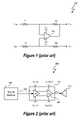
- FIG. 1depicts a closed loop amplifier circuit 100 .
- Resistors R 1 and R 2provide a voltage divider for input voltage V INM , and resistor R 2 provides feedback resistance between the output and inverting terminals of operational amplifier 102 .
- Resistors R 3 and R 4provide a voltage divider circuit between input voltage V INP and reference voltage V ref .
- Operational-amplifier 102drives the output voltage V out so that the input voltages at the inverting and noninverting terminals of operational-amplifier 102 are approximately equal.
- a power supplysupplies power to operational-amplifier 102 via voltage rails V DD and V SS to allow operational-amplifier 102 to operate.
- a multi-stage amplifierincludes multiple amplification stages.
- operational-amplifier 102includes multiple amplification stages.
- Each amplification stageutilizes power supplied by a power supply to amplify an input signal.
- the power supplyprovides a set of voltage rails, such as V DD and V SS , to each amplification stage of the multi-stage amplifier.
- voltage rail V DDrepresents a higher voltage with respect to voltage rail V SS
- voltage rail V SSrepresents a negative voltage or ground.
- FIG. 2depicts a signal processing system 200 with a conventional multistage amplifier 202 .
- Signal source 208provides analog input signal x(t), and signal source 208 can be any signal source such as a microphone or an audio and/or video device. Signal source 208 can also be any internal signal source within an integrated circuit.
- Amplifier 202includes multiple, cascaded stages to successively amplify input signal x(t). Amplifier 202 generates analog output signal y(t).
- Amplifier stages 204 and 206have respective gains g 0 and g 1 .
- Amplifier 202supplies output signal y(t) to an output device, such as speaker 210 .
- a power supply 302provides operating power to each of amplification stages 204 and 206 by providing voltage rails V DD and V SS to power supply nodes of amplification stages 204 and 206 .
- Amplification stage 204includes power supply nodes V DD IN and V SS IN to receive voltage supply rails V DD and V SS from power supply 302 .
- Amplification stage 206includes power supply nodes V DD OUT and V SS OUT to receive voltage supply rails V DD and V SS from power supply 302 .
- each of amplification stages 204 and 206has a unique set of power supply nodes to receive the set of voltage rails V DD and V SS
- the multistage amplifier 202is supplied by only one set of voltage rails, i.e. voltage rails V DD and V SS .
- FIG. 3depicts integrated circuit 304 connected to external power supply 302 .
- Amplifier 202is implemented, in this embodiment, as an integrated portion of integrated circuit 304 .
- Power supply 302is an external device that provides power to integrated circuit 304 through pads 306 and 308 .
- Pad 306receives the V DD voltage rail of power supply 302
- pad 308receives the V SS voltage rail.
- Each of pads 306 and 308has two conductive paths ( 310 , 212 ) and ( 314 , 316 ) connected to amplifier 202 .
- Efficiency of an amplification stagein terms of power loss, increases as a difference between an input signal voltage and voltage rail decreases.
- the amplifieroperates with a high degree of efficiency.
- the voltage rails to amplification stageare set so that each amplification stage operates properly.
- proper operationincludes providing sufficient bias voltages to transistors within the amplification stage for operation in a predetermined mode, such as in a saturation mode, and providing sufficient input signal headroom.
- Input signal headroomrepresents a difference between an input signal level and a maximum input signal level that can be accommodated while still allowing the amplification stage to operate. Unless otherwise indicated, “input signal headroom” is referred to herein as “headroom”.
- the voltage supply railsare fixed at specific voltage levels.
- input signalsswing between minimum and maximum voltage levels.
- the efficiency of the amplifierdecreases as the input signal decreases.
- a method of amplifying an input signalincludes receiving an input signal with a multi-stage amplifier. The method also includes receiving a mixed set of voltage rails, wherein each amplification stage of the multi-stage amplifier receives a set of the voltage rails and at least one member of one set of the voltage rails is a variable voltage rail. The method further includes amplifying the input signal using the multi-stage amplifier to generate an amplified input signal.
- a signal processing devicein another embodiment, includes a multi-stage amplifier.
- the amplifierincludes a first amplification stage having an output node and first and second power supply nodes, wherein during operation the first and second power supply nodes of the first amplification stage are coupled to respective first and second voltage rails.
- the amplifieralso includes a second amplification stage, coupled to the output node of the first amplification stage, having first and second power supply nodes, wherein during operation the first and second power supply nodes of the second amplification stage are respectively coupled to a variable voltage rail and to a third voltage rail, and the first voltage rail is greater than the variable voltage rail.
- a method of amplifying an input signalincludes receiving first and second power supply voltages with a first amplification stage of a multi-stage amplifier. The method further includes receiving third and fourth power supply voltages with a second amplification stage of the multi-stage amplifier, wherein the first power supply voltage is greater than the third power supply voltage, the third power supply voltage varies over time during operation of the multi-stage amplifier and the first and third power supply voltages are more positive than respective second and fourth power supply voltages. The method also includes receiving an input signal with the multi-stage amplifier and amplifying the input signal using the multi-stage amplifier to generate an amplified input signal.
- a signal processing systemincludes a first amplification stage, wherein during operation the first amplification stage receives a fixed supply voltage and a first variable supply voltage, and the fixed supply voltage is greater than the first variable supply voltage.
- the systemalso includes a second amplification stage, coupled to an output of the first amplification stage, wherein during operation the second amplification stage receives the fixed supply voltage and the variable supply voltage.
- the systemfurther includes a third amplification stage, coupled to an output of the second amplification stage, wherein during operation the third amplification stage receives a second variable supply voltage and the first variable supply voltage, wherein the fixed supply voltage is greater than a maximum second variable supply voltage.
- FIG. 1(labeled prior art) depicts a closed amplifier circuit.
- FIG. 2(labeled prior art) depicts a multi-stage amplifier.
- FIG. 3(labeled prior art) depicts an integrated circuit with a multi-stage amplifier connected to an external power supply.
- FIG. 4depicts a multi-stage amplifier having a mixed set of voltage rails.
- FIG. 5depicts a multi-stage amplifier in an audio signal processing system.
- FIG. 6depicts an amplification stage.
- a signal processing system and methodutilizes a multi-stage amplifier to amplify an input signal.
- the multi-stage amplifieruses a mixed set of voltage rails to improve the operating efficiency of at least one of the amplification stages while allowing other amplification stages to operate in a predetermined operating mode. Efficiency of at least one of the stages is improved by providing a different set of the amplifier stages is improved by utilizing at least one variable voltage rail supplied to an amplification stage of the multi-stage amplifier.
- the variable voltage railvaries in response to changes in an input signal voltage to the amplification stage.
- the multi-stage amplifieroperates with mixed sets of voltage supply rails to allow amplification stage efficiency and provide adequate voltage to allow operation of all amplification stages. Accordingly, at least one amplification stage utilizes a variable voltage rail, and all amplification stages are supplied with a set of voltage rails that provides sufficient input signal headroom.
- the multi-stage amplifierincludes at least first and second amplification stages.
- the two amplification stageshave different supply voltage requirements.
- the signal processing system and methodprovide a first set of voltage rails, which can be variable or fixed, to the first amplification stage and at least one variable voltage rail to the second amplification stage.
- the multi-stage amplifiercan operate more efficiently than a conventional multi-stage amplifier with a fixed set of voltage rails for each amplification stage and still maintain sufficient input signal headroom for all amplification stages.
- FIG. 4depicts a multi-stage amplifier 400 to amplify analog input signal x(t) and generate analog output signal y(t) using multiple sets of voltage rails.
- the multi-stage amplifier 400has N+1 serially connected amplification stages 402 . 0 , 402 . 1 , . . . , 402 .N, where N is an integer greater than or equal to two.
- Each of the amplification stages 402 . 0 , 402 . 1 , . . . , 402 .Nreceives two respective sets of voltage rails, ⁇ V DD — 0 , V SS — 0 ⁇ , ⁇ V DD — 1 , V SS — 1 ⁇ , . . .
- each set of voltage railsis set to provide sufficient headroom for the voltage swing of each input signal to each amplification stage. Particular values of the voltage rails depend upon the actual configuration of each of amplification stages 402 . 0 , 402 . 1 , . . . , 402 .N and the full swing of each input signal to each amplification stage.
- all the positive voltage rails, except that positive voltage rail V DD — N of the last amplification stageare equal and fixed, and the voltage rail V DD — N N of the last amplification stage is a variable voltage rail.
- At least one set of voltage railsis provided by a variable voltage supply, such as the charge pump power supply illustratively described in the Cirrus Applications.
- a variable voltage supplysuch as the charge pump power supply illustratively described in the Cirrus Applications.
- each variable voltage rail supplied by the variable voltage supplydynamically adjusts, in response to the voltage level of an input signal to the amplification stage. The adjustment reduces a difference between the voltage of the output signal and the voltage supplied to the amplification stage while providing sufficient output signal headroom. Thus, efficiency of the amplification stage stages is improved.
- amplification stages 402 . 0 , 402 . 1 , . . . , 402 .Nhas a greater voltage supply requirement to provide headroom for the input signal.
- an analog input signal x(t)has a voltage level of +V in .
- voltage rail V DD — 0equals (+V in +V ovh ).
- V ovhis an overhead voltage that allows the transistors of amplification stage 402 .
- V DD — NV DD — N .
- V DD — N(+V in +V ovh )
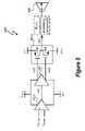
- FIG. 5depicts a multi-stage amplifier 500 , which is one embodiment of multi-stage amplifier 400 .
- the multi-stage amplifier 500is a class AB amplifier with a differential input amplification stage 502 . 0 .
- amplification stagereceives and amplifies a difference between input signals V SUMM and V SUMP .
- Amplification stage 502 . 1then amplifies the output of amplification stage 502 . 0
- amplification stage 502 . 2amplifies the dual output of amplification stage 502 . 1 .
- Amplification stage 502 . 1provides dual output signals x 2p (t) and x 2n (t).
- CMOS field effect transistor (FET) 504 and p-channel CMOS FET 506 of amplification stage 502 . 2both operate in saturation mode during normal operation of multi-stage amplifier 500 .
- Respective voltage levels of input signals x 2p (t) and x 2n (t)determine the current through the respective FETs 504 and 506 .
- FETs 504 and 506work together in accordance with the voltage levels of input signals x 2p (t) and x 2n (t) to generate an analog output signal y(t).
- One or more power suppliesprovide voltage rails V DD — 0 , V SS — 0 , V DD — 1 , and V SS — 1 to respective multi-stage amplifiers 502 . 0 , 502 . 1 , and 502 . 2 .
- At least one of the voltage railsis variable.
- voltage rail V DD — 1is variable to increase the efficiency of amplification stage 502 . 2 .
- voltage rail V SS — 1is also variable.
- V DD — 0 ⁇ V DD — 1 and V SS — 0V SS — 1
- the first and second set of voltage railsstill form a mixed set of voltage rails.
- Voltage rails V DD — 0 , V SS — 0 , and V DD — 1 , V SS — 1can be respectively fixed or variable voltage rails.
- fixed voltage railsmaintain a relatively constant voltage over time. Although fixed voltage rails can slightly vary over time due to, for example, an environmental factor such as temperature, fixed voltage rails are not responsive to any input signal to any amplification stage of multi-stage amplifier 500 and are not otherwise intentionally varied during operation of multi-stage amplifier 500 .
- amplification stages 502 . 0 and 502 . 1have different circuitry than amplification stage 502 . 2 .
- amplification stages 502 . 0 and 502 . 1operate properly with the same voltage supply rails V DD — 0 and V SS — 0 .
- voltage rail set ⁇ V DD — 0 , V SS — 0 ⁇differs from the voltage rail set ⁇ V DD — 1 , V SS — 1 ⁇ when the input signals to respective amplification stages drops below a predetermined value.
- voltage rails V DD — 0 , V SS — 0 , and V SS — 1are fixed, and voltage rail V DD — 1 is variable.
- voltage rail V DD — 1decreases to +V in while voltage rail V DD — 0 remains at (+V in ) ⁇ 2. This allows all amplification stages to operate properly, e.g. amplification stage transistors operation in saturation mode, and increases the efficiency of amplification stage 502 . 2 .
- multi-stage amplifier 500is part of an audio signal processing system.
- the multi-stage amplifier 500provides the analog output signal y(t) to speaker 508 .
- components 410such as a low pass filter, post-process the analog output signal y(t) prior to reception by speaker 508 .
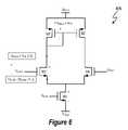
- FIG. 6depicts a schematic of amplification stage 600 , and amplification stage 600 represents one embodiment of amplification stage 502 . 0 .
- Amplification stage 600is a differential amplifier and, thus, amplifies a difference between the differential input signals V SUMM and V SUMP .
- a power supplyprovides voltage rails V DD — 0 and V SS — 0 to supply power to amplification stage 600 .
- FET M 1is connected as a diode and FETs M 1 and M 2 have common drain and gate voltages.
- FETs M 3 and M 4respectively connected to the sources of FETs M 1 and M 2 , respectively receive input signals V SUMM and V SUMP as gate voltages.
- p-channel FETs M 3 and M 4maintain a saturated state during operation of amplification stage 600 .
- P-channel FET M 5connected between voltage rail V SS — 1 and the sources of FETs M 3 and M 4 , operates as a current source.
- a bias voltage V BIAS at the gate of FET M 5biases FET M 5 .
- V DD — 0When voltage rail V DD — 0 equals or exceeds a minimum voltage and voltage rail V SS — 0 is below a minimum voltage, amplification stage 600 operates properly and provides sufficient headroom for the voltage swings of input signals V SUMM and V SUMP .
- the minimum V DD — 0 voltage railcan be determined from the schematic of amplification stage 600 .
- the drain-gate voltage of FET M 1is V DSsat +V TH — M1 .
- each of FETs M 1 , M 2 , M 3 , M 4 , and M 5has the same drain-source saturation voltage V DSsat and the same threshold voltage V TH .
- a voltage at the source of FET M 3is V SUMM ⁇ (V DSsat +V TH ).
- Voltage V xrepresents a voltage at the drain of FET M 3 .
- V xV DD — 0 ⁇ V DSsat ⁇ V TH [3]
- amplification stage 600is configured as part of an operational-amplifier with feedback to the inverting terminal, and, thus, V SUMP is approximately equal to V SUMM . From Equations [4] and [7], to maintain FETs M 1 , M 2 , M 3 , and M 4 in saturation and provide sufficient headroom for input signal V SUMM and V SUMP : V DD — 0 ⁇ V SUMM — max +V DSsat [8] V SS — 0 ⁇ V SUMM — min ⁇ 2 V DSsat ⁇ V TH [9]
- V DSsat0.100 V
- V SUMMmax+0.9 V
- V SUMMmin0 V
- V TH0.7 V
- V SUMMV SUMP , from Equation [8]
- V DD — 0is greater than or equal to +1.0 V to provide sufficient headroom and allow amplification stage 600 to operate in saturation mode.
- V SS — 0is less than or equal to ⁇ 0.9 V to provide sufficient headroom and allow amplification stage 600 to operate in saturation mode.
- V DD — 1when input signal x 2p (t) is +0.9 V, V DD — 1 can be +0.9 V and still provide sufficient headroom for input signal x 2p (t). However, from FIGS. 4 and 5 , when V SUMM is +0.9 V, V DD — 0 should be greater than or equal to +1.0 V. Also, in at least one embodiment, amplification stage 502 . 0 and 502 . 1 operate properly with the same voltage supply rails V DD — 0 and V SS — 0 . Thus, by providing different voltage rails V DD — 0 and V DD — 1 , e.g.
- amplification stages 502 . 0 and 502 . 1can operate properly in saturation mode and provide sufficient headroom for input signal V SUMM
- amplification stage 502 . 2can operate efficiently and provide sufficient headroom for input signal x 2p (t).
- amplification stages 502 . 0 , 502 . 1 , and 502 . 2can utilize the same voltage rails V SS — 0 and V SS — 1 .
- the multi-stage amplifieruses a mixed set of voltage rails to improve the operating efficiency of at least one of the amplification stages while allowing other amplification stages to operate in a predetermined operating mode.
- the signal processing systemsincluding multi-stage amplifier 400
- the signal processing systemscan be implemented using discrete, integrated, or a combination of discrete and integrated components.
- the multi-stage amplifiercan be used in any signal processing system including audio signal processing systems and video signal processing systems.
Landscapes
- Engineering & Computer Science (AREA)
- Power Engineering (AREA)
- Microelectronics & Electronic Packaging (AREA)
- Multimedia (AREA)
- Amplifiers (AREA)
Abstract
Description
This application claims the benefit under 35 U.S.C. §119(e) and 37 C.F.R. §1.78 of U.S. Provisional Application No. 60/885,673, filed Jan. 19, 2007 and entitled “Amplifier with Fixed and Variable Supply Rails.” U.S. Provisional Application No. 60/885,673 includes exemplary systems and methods and is incorporated by reference in its entirety.
1. Field of the Invention
The present invention relates in general to the field of signal processing, and more specifically to a system and method for processing signals with a multi-stage amplifier having multiple fixed and variable voltage rails.
2. Description of the Related Art
Many electronic devices utilize one or more amplifiers to amplify an electrical signal. For example, in an audio context, a microphone utilizes transducers to convert sound waves into a corresponding electrical signal. An audio and/or video playback device reads stored data and converts the data into an electrical signal. The electrical signal often has insufficient power to drive an output device such as an audio speaker. An amplifier amplifies the smaller electrical signal to a level sufficient to drive the output device. Conventional amplifiers utilize a single set of voltage rails to supply voltage rails to a multi-stage amplifier.
A multi-stage amplifier includes multiple amplification stages. In at least one embodiment, operational-amplifier 102 includes multiple amplification stages. Each amplification stage utilizes power supplied by a power supply to amplify an input signal. The power supply provides a set of voltage rails, such as VDDand VSS, to each amplification stage of the multi-stage amplifier. In at least one embodiment, voltage rail VDDrepresents a higher voltage with respect to voltage rail VSS, and voltage rail VSSrepresents a negative voltage or ground.
Referring toFIGS. 2 and 3 , apower supply 302 provides operating power to each ofamplification stages amplification stages Amplification stage 204 includes power supply nodes VDDIN and VSSIN to receive voltage supply rails VDDand VSSfrompower supply 302.Amplification stage 206 includes power supply nodes VDDOUT and VSSOUT to receive voltage supply rails VDDand VSSfrompower supply 302. As discussed with reference toFIG. 3 , although each ofamplification stages multistage amplifier 202 is supplied by only one set of voltage rails, i.e. voltage rails VDDand VSS.
Efficiency of an amplification stage, in terms of power loss, increases as a difference between an input signal voltage and voltage rail decreases. Thus, when the input signal voltage approximately equals the supplied voltage rail, the amplifier operates with a high degree of efficiency.
However, to amplify a signal, the voltage rails to amplification stage are set so that each amplification stage operates properly. In at least one embodiment, proper operation includes providing sufficient bias voltages to transistors within the amplification stage for operation in a predetermined mode, such as in a saturation mode, and providing sufficient input signal headroom. Input signal headroom represents a difference between an input signal level and a maximum input signal level that can be accommodated while still allowing the amplification stage to operate. Unless otherwise indicated, “input signal headroom” is referred to herein as “headroom”.
To provide sufficient headroom during operation, the voltage supply rails are fixed at specific voltage levels. During operation, input signals swing between minimum and maximum voltage levels. Thus, the efficiency of the amplifier decreases as the input signal decreases.
In one embodiment of the present invention, a method of amplifying an input signal includes receiving an input signal with a multi-stage amplifier. The method also includes receiving a mixed set of voltage rails, wherein each amplification stage of the multi-stage amplifier receives a set of the voltage rails and at least one member of one set of the voltage rails is a variable voltage rail. The method further includes amplifying the input signal using the multi-stage amplifier to generate an amplified input signal.
In another embodiment of the present invention, a signal processing device includes a multi-stage amplifier. The amplifier includes a first amplification stage having an output node and first and second power supply nodes, wherein during operation the first and second power supply nodes of the first amplification stage are coupled to respective first and second voltage rails. The amplifier also includes a second amplification stage, coupled to the output node of the first amplification stage, having first and second power supply nodes, wherein during operation the first and second power supply nodes of the second amplification stage are respectively coupled to a variable voltage rail and to a third voltage rail, and the first voltage rail is greater than the variable voltage rail.
In a further embodiment of the invention, a method of amplifying an input signal includes receiving first and second power supply voltages with a first amplification stage of a multi-stage amplifier. The method further includes receiving third and fourth power supply voltages with a second amplification stage of the multi-stage amplifier, wherein the first power supply voltage is greater than the third power supply voltage, the third power supply voltage varies over time during operation of the multi-stage amplifier and the first and third power supply voltages are more positive than respective second and fourth power supply voltages. The method also includes receiving an input signal with the multi-stage amplifier and amplifying the input signal using the multi-stage amplifier to generate an amplified input signal.
In a further embodiment of the invention, a signal processing system includes a first amplification stage, wherein during operation the first amplification stage receives a fixed supply voltage and a first variable supply voltage, and the fixed supply voltage is greater than the first variable supply voltage. The system also includes a second amplification stage, coupled to an output of the first amplification stage, wherein during operation the second amplification stage receives the fixed supply voltage and the variable supply voltage. The system further includes a third amplification stage, coupled to an output of the second amplification stage, wherein during operation the third amplification stage receives a second variable supply voltage and the first variable supply voltage, wherein the fixed supply voltage is greater than a maximum second variable supply voltage.
The present invention may be better understood, and its numerous objects, features and advantages made apparent to those skilled in the art by referencing the accompanying drawings. The use of the same reference number throughout the several figures designates a like or similar element.
A signal processing system and method utilizes a multi-stage amplifier to amplify an input signal. The multi-stage amplifier uses a mixed set of voltage rails to improve the operating efficiency of at least one of the amplification stages while allowing other amplification stages to operate in a predetermined operating mode. Efficiency of at least one of the stages is improved by providing a different set of the amplifier stages is improved by utilizing at least one variable voltage rail supplied to an amplification stage of the multi-stage amplifier. The variable voltage rail varies in response to changes in an input signal voltage to the amplification stage. For amplifier stages having different voltage supply requirements, the multi-stage amplifier operates with mixed sets of voltage supply rails to allow amplification stage efficiency and provide adequate voltage to allow operation of all amplification stages. Accordingly, at least one amplification stage utilizes a variable voltage rail, and all amplification stages are supplied with a set of voltage rails that provides sufficient input signal headroom.
In at least one embodiment, the multi-stage amplifier includes at least first and second amplification stages. The two amplification stages have different supply voltage requirements. During operation of the multi-stage amplifier, the signal processing system and method provide a first set of voltage rails, which can be variable or fixed, to the first amplification stage and at least one variable voltage rail to the second amplification stage. Thus, the multi-stage amplifier can operate more efficiently than a conventional multi-stage amplifier with a fixed set of voltage rails for each amplification stage and still maintain sufficient input signal headroom for all amplification stages.
Commonly assigned U.S. patent application Ser. No. 11/610,498, filed 13 Dec. 2006, entitled “Energy-Efficient Consumer Device Audio Power Output Stage” and U.S. patent application Ser. No. 11/611,069, filed 14 Dec. 2006, and entitled “Method and Apparatus for Controlling a Selectable Voltage Audio Power Output Stage” describe illustrative method and apparatus embodiments of providing a variable voltage rail for an audio power stage. The Cirrus Applications describe utilizing a charge pump to vary the supply voltage to an amplifier depending upon the voltage level of the input signal. In at least one embodiment, the charge pump dynamically varies the supply voltage to decrease a difference between the input signal voltage and the amplifier supply voltage, thus, increasing the efficiency of the amplifier. U.S. patent application Ser. Nos. 11/610,498 and 11/611,069 (collectively referred to herein as the “Cirrus Applications”) claim priority to U.S. Provisional Application No. 60/823,036 filed on 21 Aug. 2006, and the Cirrus Applications are incorporated herein by reference in their entireties.
In at least one embodiment, at least one set of voltage rails is provided by a variable voltage supply, such as the charge pump power supply illustratively described in the Cirrus Applications. In at least one embodiment, for each amplification stage connected to the variable voltage supply, each variable voltage rail supplied by the variable voltage supply dynamically adjusts, in response to the voltage level of an input signal to the amplification stage. The adjustment reduces a difference between the voltage of the output signal and the voltage supplied to the amplification stage while providing sufficient output signal headroom. Thus, efficiency of the amplification stage stages is improved.
Different amplification stages have different voltage supply requirements for providing sufficient headroom and operational efficiency. For the same input signal level, at least one of the amplification stages402.0,402.1, . . . ,402.N has a greater voltage supply requirement to provide headroom for the input signal. For example, in at least one embodiment, an analog input signal x(t) has a voltage level of +Vin. To provide sufficient headroom for the input signal x(t) and allow the transistors of amplification stage402.0 operate in saturation mode, voltage rail VDD— 0equals (+Vin+Vovh). “Vovh” is an overhead voltage that allows the transistors of amplification stage402.0 to operate in saturation mode when the voltage level of analog input signal x(t) equals +Vin. For the same analog input signal x(t), voltage rail VDD— Nfor amplification stage402.N equals +Vin. Thus, for analog input signal x(t) having a voltage level of +Vinand for amplification stages402.0 and402.N to operate properly, VDD— 0>VDD— N. Thus, in this example, if VDD— 0=VDD— N=+Vin, amplification stage402.0 will not operate properly. If VDD— 0=VDD— N=(+Vin+Vovh), amplification stage402.N does not operate as efficiently relative to voltage rail VDD— N=+Vin.
One or more power supplies provide voltage rails VDD— 0, VSS— 0, VDD— 1, and VSS— 1to respective multi-stage amplifiers502.0,502.1, and502.2. At least one of the voltage rails is variable. For example, in at least one embodiment, voltage rail VDD— 1is variable to increase the efficiency of amplification stage502.2. In at least one embodiment, voltage rail VSS— 1is also variable. The first set of voltage rails, {VDD— 0, VSS— 0}, and the second set of voltage rails, {VDD— 1, VSS— 1}, form an exemplary mixed set of voltage rails because the sets are not identical, although each set may have a common member. For example, if voltage rail VDD— 0≠VDD— 1and VSS— 0=VSS— 1, the first and second set of voltage rails still form a mixed set of voltage rails. Voltage rails VDD— 0, VSS— 0, and VDD— 1, VSS— 1, can be respectively fixed or variable voltage rails. During operation ofmulti-stage amplifier 500, fixed voltage rails maintain a relatively constant voltage over time. Although fixed voltage rails can slightly vary over time due to, for example, an environmental factor such as temperature, fixed voltage rails are not responsive to any input signal to any amplification stage ofmulti-stage amplifier 500 and are not otherwise intentionally varied during operation ofmulti-stage amplifier 500.
In at least one embodiment, amplification stages502.0 and502.1 have different circuitry than amplification stage502.2. In at least one embodiment, amplification stages502.0 and502.1 operate properly with the same voltage supply rails VDD— 0and VSS— 0. To allow amplification stages502.0 and502.1 to operate, e.g. to amplify a signal, and provide sufficient headroom for input signals VSUMM, VSUMP, x1(t), x2p(t), and x2n(t) and allow amplification stage502.2 to operate efficiently, voltage rail set {VDD— 0, VSS— 0} differs from the voltage rail set {VDD— 1, VSS— 1} when the input signals to respective amplification stages drops below a predetermined value. For example, in at least one embodiment, voltage rails VDD— 0, VSS— 0, and VSS— 1are fixed, and voltage rail VDD— 1is variable. When the input signal x2p(t) is below +Vin, voltage rail VDD— 1decreases to +Vinwhile voltage rail VDD— 0remains at (+Vin)·2. This allows all amplification stages to operate properly, e.g. amplification stage transistors operation in saturation mode, and increases the efficiency of amplification stage502.2.
In at least one embodiment,multi-stage amplifier 500 is part of an audio signal processing system. Themulti-stage amplifier 500 provides the analog output signal y(t) tospeaker 508. In at least one embodiment, components410, such as a low pass filter, post-process the analog output signal y(t) prior to reception byspeaker 508.
When voltage rail VDD— 0equals or exceeds a minimum voltage and voltage rail VSS— 0is below a minimum voltage,amplification stage 600 operates properly and provides sufficient headroom for the voltage swings of input signals VSUMMand VSUMP. The minimum VDD— 0voltage rail can be determined from the schematic ofamplification stage 600. During operation, the drain-gate voltage of FET M1 is VDSsat+VTH— M1. Assuming that FETs M1, M2, M3, M4, and M5 are matched, each of FETs M1, M2, M3, M4, and M5 has the same drain-source saturation voltage VDSsatand the same threshold voltage VTH. A voltage at the source of FET M3 is VSUMM−(VDSsat+VTH). Voltage Vxrepresents a voltage at the drain of FET M3. Thus:
Vx≧VSUMM— max−(VDSsat+VTH)+VDSsat [1]
Vx≧VSUMM— max−VTH [2]
Vx=VDD— 0−VDSsat−VTH [3]
Vx≧VSUMM
Vx≧VSUMM
Vx=VDD
- Substituting Equation [3] into Equation [2]:
VDD— 0−VDSsat−VTH≧VSUMM— max−VTH [4]
- Substituting Equation [3] into Equation [2]:
To provide sufficient headroom voltage for input signal voltages VSUMMand VSUMP, VDD— 0−VSS— 0≧headroom voltage. Thus, to provide sufficient headroom voltage:
VSUMP≧2·VDSsat+VTH+VSS— 0 [5]
rearranging Equation [5] yields:
VSS— 0≦VSUMP−2·VDSsat−VTH [6]
VSS— 0≦VSUMP— min−2VDSsat−VTH [7]
VSUMP≧2·VDSsat+VTH+VSS
rearranging Equation [5] yields:
VSS
VSS
In at least one embodiment,amplification stage 600 is configured as part of an operational-amplifier with feedback to the inverting terminal, and, thus, VSUMPis approximately equal to VSUMM. From Equations [4] and [7], to maintain FETs M1, M2, M3, and M4 in saturation and provide sufficient headroom for input signal VSUMMand VSUMP:
VDD— 0≧VSUMM— max+VDSsat [8]
VSS— 0≦VSUMM— min−2VDSsat−VTH [9]
VDD
VSS
The power supply requirements of at least one embodiment of amplification stages502.0 and502.2 can be met by providing a mixed set of voltage rails to amplification stages502.0 and502.2. In at least one embodiment, VDSsat=0.100 V, VSUMMmax=+0.9 V, VSUMMmin=0 V, VTH=0.7 V, and VSUMM=VSUMP, from Equation [8], VDD— 0is greater than or equal to +1.0 V to provide sufficient headroom and allowamplification stage 600 to operate in saturation mode. From Equation [9], VSS— 0is less than or equal to −0.9 V to provide sufficient headroom and allowamplification stage 600 to operate in saturation mode. As discussed above with reference toFIG. 5 , when input signal x2p(t) is +0.9 V, VDD— 1can be +0.9 V and still provide sufficient headroom for input signal x2p(t). However, fromFIGS. 4 and 5 , when VSUMMis +0.9 V, VDD— 0should be greater than or equal to +1.0 V. Also, in at least one embodiment, amplification stage502.0 and502.1 operate properly with the same voltage supply rails VDD— 0and VSS— 0. Thus, by providing different voltage rails VDD— 0and VDD— 1, e.g. VDD— 0=+1.0 V and VDD— 1=+0.9 V, amplification stages502.0 and502.1 can operate properly in saturation mode and provide sufficient headroom for input signal VSUMM, and amplification stage502.2 can operate efficiently and provide sufficient headroom for input signal x2p(t). Additionally, in at least one embodiment, amplification stages502.0,502.1, and502.2 can utilize the same voltage rails VSS— 0and VSS— 1.
Thus, the multi-stage amplifier uses a mixed set of voltage rails to improve the operating efficiency of at least one of the amplification stages while allowing other amplification stages to operate in a predetermined operating mode.
Although the present invention has been described in detail, it should be understood that various changes, substitutions and alterations can be made hereto without departing from the spirit and scope of the invention as defined by the appended claims. For example, the signal processing systems, includingmulti-stage amplifier 400, can be implemented using discrete, integrated, or a combination of discrete and integrated components. Additionally, the multi-stage amplifier can be used in any signal processing system including audio signal processing systems and video signal processing systems.
Claims (24)
1. A method of amplifying an input signal, the method comprising:
receiving an input signal with a multi-stage amplifier;
receiving a mixed set of voltage rails, wherein each amplification stage of the multi-stage amplifier receives a set of the voltage rails and at least two of the stages of the multi-stage amplifier receive at least one variable voltage rail, wherein each variable voltage rail varies in accordance with one or more variations of an amplitude of the input signal to decrease a difference between a voltage of the input signal and voltages of the variable voltage rails;
amplifying the input signal using the multi-stage amplifier to generate an amplified input signal; and
utilizing a charge pump to dynamically vary the at least one variable voltage rail depending upon variations of a voltage level of the input signal.
2. The method ofclaim 1 wherein the set of voltage rails received by a last stage of the multi-stage amplifier comprises two variable voltage rails.
3. The method ofclaim 2 wherein the set of voltage rails for each of the stages of the multi-stage amplifier includes one of the variable voltage rails received by the last stage of the multi-stage amplifier and the set of voltage rails received by each of the stages of the multi-stage amplifier except the last stage also includes a fixed voltage rail.
4. The method ofclaim 1 wherein the input signal comprises an audio signal, the method further comprising:
providing the amplified input signal to at least one speaker.
5. The method ofclaim 1 further comprising:
for each amplification stage, generating an output signal;
for each amplification stage, except an initial amplification stage, receiving the output signal of a preceding amplification stage; and
receiving the variable voltage rail with one of the amplification stages, wherein the variable voltage rail received by the amplification stage varies in response to the output signal received by the amplification stage to increase efficiency of the amplification stage.
6. The method ofclaim 1 wherein the mixed set of voltage rails comprises fixed voltage rails and the variable voltage rail.
7. A signal processing device comprising:
a multi-stage amplifier, the amplifier comprising:
a first amplification stage having an output node and first and second power supply nodes, wherein during operation the first and second power supply nodes of the first amplification stage are coupled to respective first and second voltage rails, and at least one of the first and second voltage rails is a first variable voltage rail and each variable voltage rail varies in accordance with one or more variations of an amplitude of the input signal;
a second amplification stage, coupled to the output node of the first amplification stage, having first and second power supply nodes, wherein during operation the first and second power supply nodes of the second amplification stage are respectively coupled to a second variable voltage rail and a third variable voltage rail; and
a charge pump to dynamically vary at least one of the variable voltage rails depending upon variations of a voltage level of the input signal.
8. The signal processing system ofclaim 7 wherein during operation of the multi-stage amplifier, the first and second voltage rails are variable voltage rails.
9. The signal processing system ofclaim 7 wherein, during operation of the multi-stage amplifier, the first and the second voltage rails vary over time.
10. The signal processing system ofclaim 7 wherein the multi-stage amplifier further comprises:
a third amplification stage, coupled between the first and second amplification stages, having first and second power supply nodes, wherein during operation the first and second power supply nodes of the third amplification stage are coupled respectively to the first and second voltage rails.
11. The signal processing system ofclaim 7 wherein the multi-stage amplifier further comprises at least one input terminal to receive an audio input signal and at least one output terminal to supply an amplified version of the audio input signal.
12. The signal processing system ofclaim 7 wherein the multi-stage amplifier further comprises at least one input terminal to receive an audio input signal and at least one output terminal to supply an amplified version of the audio input signal, the system further comprising:
an input source of the audio input signal coupled to the input terminal to supply the audio input signal to the multi-stage amplifier; and
at least one speaker coupled to the output terminal of the multi-stage amplifier.
13. The signal processing system ofclaim 7 further comprising:
a first power supply coupled to the first power supply node of the first amplification stage; and
a second power supply coupled to the second power supply node of the first amplification stage and to the first and second power supply nodes of the second amplification stage.
14. The signal processing system ofclaim 7 wherein the multi-stage amplifier comprises integrated circuit components.
15. A method of amplifying an input signal, the method comprising:
receiving first and second power supply voltages with a first amplification stage of a multi-stage amplifier;
receiving third and fourth power supply voltages with a second amplification stage of the multi-stage amplifier, wherein the first power supply voltage is greater than the third power supply voltage, the third and fourth power supply voltages vary over time during operation of the multi-stage amplifier and the first and third power supply voltages are more positive than respective second and fourth power supply voltages;
receiving an input signal with the multi-stage amplifier;
amplifying the input signal using the multi-stage amplifier to generate an amplified input signal; and
utilizing a charge pump to dynamically vary each of the variable voltage rails depending upon variations of a voltage level of the input signal.
16. The method ofclaim 15 wherein the first and second power supply voltages vary over time during operation of the multi-stage amplifier.
17. The method ofclaim 15 wherein the second power supply voltage and the third power supply voltage vary over time during operation of the multi-stage amplifier, and the first power supply voltage is fixed.
18. The method ofclaim 15 further comprising:
supplying the first and second power supply voltages to a third amplification stage of the multi-stage amplifier, wherein the third amplification stage is an intermediary amplification stage.
19. The method ofclaim 15 further comprising:
providing the amplified input signal to at least one speaker.
20. A signal processing system comprising:
a first amplification stage, wherein during operation the first amplification stage receives an input signal to the signal processing system and receives a fixed supply voltage and a first variable supply voltage, and the fixed supply voltage is greater than the first variable supply voltage;
a second amplification stage, coupled to an output of the first amplification stage, wherein during operation the second amplification stage receives the fixed supply voltage and the first variable supply voltage; and
a third amplification stage, coupled to an output of the second amplification stage, wherein during operation the third amplification stage receives a second variable supply voltage and the first variable supply voltage, wherein the fixed supply voltage is greater than a maximum second variable supply voltage; and
a charge pump to dynamically vary each of the variable voltage rails depending upon variations of a voltage level of the input signal.
21. The signal processing system ofclaim 20 further comprising:
an audio input signal generator, coupled to an input of the first amplification stage; and
at least one speaker coupled to an output of the third amplification stage.
22. The signal processing system ofclaim 21 further comprising:
a first power supply coupled to the first amplification stage to provide the fixed supply voltage; and
a second power supply coupled to the second and third amplification stages to provide the first and second variable supply voltages.
23. The signal processing system ofclaim 20 wherein the first amplification stage includes differential input nodes.
24. The method ofclaim 1 wherein the set of voltage rails for each of the stages of the multi-stage amplifier includes two variable voltage rails.
Priority Applications (4)
| Application Number | Priority Date | Filing Date | Title |
|---|---|---|---|
| US11/694,348US8362838B2 (en) | 2007-01-19 | 2007-03-30 | Multi-stage amplifier with multiple sets of fixed and variable voltage rails |
| GB0912435AGB2458081B8 (en) | 2007-01-19 | 2008-01-15 | Multi-stage amplifier with multiple sets of fixed and variable voltage rails |
| CN200880002403.2ACN101584112B (en) | 2007-01-19 | 2008-01-15 | There is many groups and fix the casacade multi-amplifier with variable voltage rails |
| PCT/US2008/051072WO2008089182A1 (en) | 2007-01-19 | 2008-01-15 | Multi-stage amplifier with multiple sets of fixed and variable voltage rails |
Applications Claiming Priority (2)
| Application Number | Priority Date | Filing Date | Title |
|---|---|---|---|
| US88567307P | 2007-01-19 | 2007-01-19 | |
| US11/694,348US8362838B2 (en) | 2007-01-19 | 2007-03-30 | Multi-stage amplifier with multiple sets of fixed and variable voltage rails |
Publications (2)
| Publication Number | Publication Date |
|---|---|
| US20080174372A1 US20080174372A1 (en) | 2008-07-24 |
| US8362838B2true US8362838B2 (en) | 2013-01-29 |
Family
ID=39401001
Family Applications (1)
| Application Number | Title | Priority Date | Filing Date |
|---|---|---|---|
| US11/694,348Active2030-01-20US8362838B2 (en) | 2007-01-19 | 2007-03-30 | Multi-stage amplifier with multiple sets of fixed and variable voltage rails |
Country Status (4)
| Country | Link |
|---|---|
| US (1) | US8362838B2 (en) |
| CN (1) | CN101584112B (en) |
| GB (1) | GB2458081B8 (en) |
| WO (1) | WO2008089182A1 (en) |
Cited By (1)
| Publication number | Priority date | Publication date | Assignee | Title |
|---|---|---|---|---|
| US20150172826A1 (en)* | 2013-12-16 | 2015-06-18 | Infineon Technologies Ag | Circuit Assembly for Processing an Input Signal, Microphone Assembly and Method for Following an Input Signal |
Families Citing this family (40)
| Publication number | Priority date | Publication date | Assignee | Title |
|---|---|---|---|---|
| GB2446843B (en) | 2006-06-30 | 2011-09-07 | Wolfson Microelectronics Plc | Amplifier circuit and methods of operation thereof |
| US8076920B1 (en) | 2007-03-12 | 2011-12-13 | Cirrus Logic, Inc. | Switching power converter and control system |
| US8174204B2 (en) | 2007-03-12 | 2012-05-08 | Cirrus Logic, Inc. | Lighting system with power factor correction control data determined from a phase modulated signal |
| US8018171B1 (en) | 2007-03-12 | 2011-09-13 | Cirrus Logic, Inc. | Multi-function duty cycle modifier |
| US7667408B2 (en)* | 2007-03-12 | 2010-02-23 | Cirrus Logic, Inc. | Lighting system with lighting dimmer output mapping |
| US7554473B2 (en)* | 2007-05-02 | 2009-06-30 | Cirrus Logic, Inc. | Control system using a nonlinear delta-sigma modulator with nonlinear process modeling |
| US8102127B2 (en) | 2007-06-24 | 2012-01-24 | Cirrus Logic, Inc. | Hybrid gas discharge lamp-LED lighting system |
| US7804697B2 (en)* | 2007-12-11 | 2010-09-28 | Cirrus Logic, Inc. | History-independent noise-immune modulated transformer-coupled gate control signaling method and apparatus |
| KR101413650B1 (en)* | 2008-01-16 | 2014-07-01 | 삼성전자주식회사 | A buffer amplifier that does not deteriorate offset characteristics and consumes less dynamic power, and a display driver including the buffer amplifier |
| US8576589B2 (en) | 2008-01-30 | 2013-11-05 | Cirrus Logic, Inc. | Switch state controller with a sense current generated operating voltage |
| US8008898B2 (en) | 2008-01-30 | 2011-08-30 | Cirrus Logic, Inc. | Switching regulator with boosted auxiliary winding supply |
| US7755525B2 (en) | 2008-01-30 | 2010-07-13 | Cirrus Logic, Inc. | Delta sigma modulator with unavailable output values |
| US8022683B2 (en) | 2008-01-30 | 2011-09-20 | Cirrus Logic, Inc. | Powering a power supply integrated circuit with sense current |
| US7759881B1 (en) | 2008-03-31 | 2010-07-20 | Cirrus Logic, Inc. | LED lighting system with a multiple mode current control dimming strategy |
| US7612615B1 (en)* | 2008-06-12 | 2009-11-03 | Mediatek Inc. | Dual supply amplifier |
| US8008902B2 (en) | 2008-06-25 | 2011-08-30 | Cirrus Logic, Inc. | Hysteretic buck converter having dynamic thresholds |
| US8847719B2 (en) | 2008-07-25 | 2014-09-30 | Cirrus Logic, Inc. | Transformer with split primary winding |
| US8344707B2 (en) | 2008-07-25 | 2013-01-01 | Cirrus Logic, Inc. | Current sensing in a switching power converter |
| US8212491B2 (en) | 2008-07-25 | 2012-07-03 | Cirrus Logic, Inc. | Switching power converter control with triac-based leading edge dimmer compatibility |
| US8487546B2 (en) | 2008-08-29 | 2013-07-16 | Cirrus Logic, Inc. | LED lighting system with accurate current control |
| US8222872B1 (en) | 2008-09-30 | 2012-07-17 | Cirrus Logic, Inc. | Switching power converter with selectable mode auxiliary power supply |
| US8179110B2 (en) | 2008-09-30 | 2012-05-15 | Cirrus Logic Inc. | Adjustable constant current source with continuous conduction mode (“CCM”) and discontinuous conduction mode (“DCM”) operation |
| US7880548B2 (en) | 2008-10-21 | 2011-02-01 | Analog Devices, Inc. | Headphone amplifier circuit |
| US8288954B2 (en) | 2008-12-07 | 2012-10-16 | Cirrus Logic, Inc. | Primary-side based control of secondary-side current for a transformer |
| US8299722B2 (en) | 2008-12-12 | 2012-10-30 | Cirrus Logic, Inc. | Time division light output sensing and brightness adjustment for different spectra of light emitting diodes |
| US8362707B2 (en) | 2008-12-12 | 2013-01-29 | Cirrus Logic, Inc. | Light emitting diode based lighting system with time division ambient light feedback response |
| US7994863B2 (en) | 2008-12-31 | 2011-08-09 | Cirrus Logic, Inc. | Electronic system having common mode voltage range enhancement |
| US8482223B2 (en) | 2009-04-30 | 2013-07-09 | Cirrus Logic, Inc. | Calibration of lamps |
| US8198874B2 (en)* | 2009-06-30 | 2012-06-12 | Cirrus Logic, Inc. | Switching power converter with current sensing transformer auxiliary power supply |
| US8212493B2 (en) | 2009-06-30 | 2012-07-03 | Cirrus Logic, Inc. | Low energy transfer mode for auxiliary power supply operation in a cascaded switching power converter |
| US8248145B2 (en) | 2009-06-30 | 2012-08-21 | Cirrus Logic, Inc. | Cascode configured switching using at least one low breakdown voltage internal, integrated circuit switch to control at least one high breakdown voltage external switch |
| US8963535B1 (en) | 2009-06-30 | 2015-02-24 | Cirrus Logic, Inc. | Switch controlled current sensing using a hall effect sensor |
| US9155174B2 (en) | 2009-09-30 | 2015-10-06 | Cirrus Logic, Inc. | Phase control dimming compatible lighting systems |
| US8654483B2 (en)* | 2009-11-09 | 2014-02-18 | Cirrus Logic, Inc. | Power system having voltage-based monitoring for over current protection |
| DE102011010506B4 (en)* | 2011-02-07 | 2017-10-26 | Tdk Corporation | microphone array |
| TWI495262B (en)* | 2012-02-24 | 2015-08-01 | Novatek Microelectronics Corp | Multi power domain operational amplifier and voltage generator using the same |
| CN103580622A (en)* | 2012-08-01 | 2014-02-12 | 联咏科技股份有限公司 | Signal amplifier |
| EP3685506B1 (en)* | 2017-06-13 | 2024-03-06 | Firecomms Limited | A low-noise transimpedance amplifier incorporating a regulator |
| EP3739327B1 (en)* | 2019-05-16 | 2022-08-31 | EM Microelectronic-Marin SA | Electrochemical sensor with interface circuit |
| DE102020210270A1 (en)* | 2020-08-13 | 2022-02-17 | Robert Bosch Gesellschaft mit beschränkter Haftung | Readout circuit for a MEMS sensor unit |
Citations (99)
| Publication number | Priority date | Publication date | Assignee | Title |
|---|---|---|---|---|
| GB2043382A (en) | 1979-02-13 | 1980-10-01 | Philips Nv | Amplifier and power supply circuit |
| US4414493A (en) | 1981-10-06 | 1983-11-08 | Thomas Industries Inc. | Light dimmer for solid state ballast |
| US4677366A (en) | 1986-05-12 | 1987-06-30 | Pioneer Research, Inc. | Unity power factor power supply |
| US4721919A (en) | 1986-12-22 | 1988-01-26 | General Motors Corporation | Class G bridge amplifier with unipolar supplies |
| US4786880A (en)* | 1986-11-14 | 1988-11-22 | U.S. Philips Corporation | Filter arrangement |
| US4797633A (en) | 1987-03-20 | 1989-01-10 | Video Sound, Inc. | Audio amplifier |
| US4940929A (en) | 1989-06-23 | 1990-07-10 | Apollo Computer, Inc. | AC to DC converter with unity power factor |
| US4973919A (en) | 1989-03-23 | 1990-11-27 | Doble Engineering Company | Amplifying with directly coupled, cascaded amplifiers |
| US5200711A (en) | 1990-10-26 | 1993-04-06 | AB Lab. Gruppen Andersson & Bavholm | Pulse-width modulated, linear audio-power amplifier |
| US5278490A (en) | 1990-09-04 | 1994-01-11 | California Institute Of Technology | One-cycle controlled switching circuit |
| US5323157A (en) | 1993-01-15 | 1994-06-21 | Motorola, Inc. | Sigma-delta digital-to-analog converter with reduced noise |
| US5359180A (en) | 1992-10-02 | 1994-10-25 | General Electric Company | Power supply system for arcjet thrusters |
| US5477481A (en) | 1991-02-15 | 1995-12-19 | Crystal Semiconductor Corporation | Switched-capacitor integrator with chopper stabilization performed at the sampling rate |
| US5481178A (en) | 1993-03-23 | 1996-01-02 | Linear Technology Corporation | Control circuit and method for maintaining high efficiency over broad current ranges in a switching regulator circuit |
| US5565761A (en) | 1994-09-02 | 1996-10-15 | Micro Linear Corp | Synchronous switching cascade connected offline PFC-PWM combination power converter controller |
| US5747977A (en) | 1995-03-30 | 1998-05-05 | Micro Linear Corporation | Switching regulator having low power mode responsive to load power consumption |
| US5777519A (en) | 1996-07-18 | 1998-07-07 | Simopoulos; Anastasios V. | High efficiency power amplifier |
| US5783909A (en) | 1997-01-10 | 1998-07-21 | Relume Corporation | Maintaining LED luminous intensity |
| US5825248A (en) | 1995-10-25 | 1998-10-20 | Pioneer Electronic Corporation | Low power consuming balanced transformer less amplifier device |
| US5963086A (en) | 1997-08-08 | 1999-10-05 | Velodyne Acoustics, Inc. | Class D amplifier with switching control |
| US6016038A (en) | 1997-08-26 | 2000-01-18 | Color Kinetics, Inc. | Multicolored LED lighting method and apparatus |
| US6043633A (en) | 1998-06-05 | 2000-03-28 | Systel Development & Industries | Power factor correction method and apparatus |
| US6072969A (en) | 1996-03-05 | 2000-06-06 | Canon Kabushiki Kaisha | Developing cartridge |
| EP1014563A1 (en) | 1998-12-14 | 2000-06-28 | Alcatel | Amplifier arrangement with voltage gain and reduced power consumption |
| US6084450A (en) | 1997-01-14 | 2000-07-04 | The Regents Of The University Of California | PWM controller with one cycle response |
| US6083276A (en) | 1998-06-11 | 2000-07-04 | Corel, Inc. | Creating and configuring component-based applications using a text-based descriptive attribute grammar |
| US6211626B1 (en) | 1997-08-26 | 2001-04-03 | Color Kinetics, Incorporated | Illumination components |
| US6211627B1 (en) | 1997-07-29 | 2001-04-03 | Michael Callahan | Lighting systems |
| US6229271B1 (en) | 2000-02-24 | 2001-05-08 | Osram Sylvania Inc. | Low distortion line dimmer and dimming ballast |
| US6246183B1 (en) | 2000-02-28 | 2001-06-12 | Litton Systems, Inc. | Dimmable electrodeless light source |
| US6259614B1 (en) | 1999-07-12 | 2001-07-10 | International Rectifier Corporation | Power factor correction control circuit |
| US6304473B1 (en) | 2000-06-02 | 2001-10-16 | Iwatt | Operating a power converter at optimal efficiency |
| EP1164819A1 (en) | 2000-06-15 | 2001-12-19 | City University of Hong Kong | Dimmable electronic ballast |
| WO2001097384A2 (en) | 2000-06-12 | 2001-12-20 | Cirrus Logic, Inc. | Real time correction of a digital pwm amplifier |
| US6344811B1 (en) | 1999-03-16 | 2002-02-05 | Audio Logic, Inc. | Power supply compensation for noise shaped, digital amplifiers |
| WO2002027944A2 (en) | 2000-09-29 | 2002-04-04 | Teradyne, Inc. | Digital to analog converter employing sigma-delta loop and feedback dac model |
| EP1213823A2 (en) | 2000-12-04 | 2002-06-12 | Sanken Electric Co., Ltd. | DC-to-DC converter |
| US6445600B2 (en) | 1998-07-13 | 2002-09-03 | Ben-Gurion University Of The Negev Research & Development Authority | Modular structure of an apparatus for regulating the harmonics of current drawn from power lines by an electronic load |
| US20020145041A1 (en) | 2001-03-16 | 2002-10-10 | Koninklijke Philips Electronics N.V. | RGB LED based light driver using microprocessor controlled AC distributed power system |
| US20020166073A1 (en) | 2001-05-02 | 2002-11-07 | Nguyen James Hung | Apparatus and method for adaptively controlling power supplied to a hot-pluggable subsystem |
| WO2002091805A2 (en) | 2001-05-10 | 2002-11-14 | Color Kinetics Incorporated | Systems and methods for synchronizing lighting effects |
| US6509913B2 (en) | 1998-04-30 | 2003-01-21 | Openwave Systems Inc. | Configurable man-machine interface |
| US20030058039A1 (en)* | 2001-09-27 | 2003-03-27 | Masao Noro | Self-operating PWM amplifier |
| US6583550B2 (en) | 2000-10-24 | 2003-06-24 | Toyoda Gosei Co., Ltd. | Fluorescent tube with light emitting diodes |
| US6636003B2 (en) | 2000-09-06 | 2003-10-21 | Spectrum Kinetics | Apparatus and method for adjusting the color temperature of white semiconduct or light emitters |
| US20030223255A1 (en) | 2002-05-31 | 2003-12-04 | Green Power Technologies Ltd. | Method and apparatus for active power factor correction with minimum input current distortion |
| US6713974B2 (en) | 2002-01-10 | 2004-03-30 | Lightech Electronic Industries Ltd. | Lamp transformer for use with an electronic dimmer and method for use thereof for reducing acoustic noise |
| US6727832B1 (en) | 2002-11-27 | 2004-04-27 | Cirrus Logic, Inc. | Data converters with digitally filtered pulse width modulation output stages and methods and systems using the same |
| US20040085117A1 (en) | 2000-12-06 | 2004-05-06 | Joachim Melbert | Method and device for switching on and off power semiconductors, especially for the torque-variable operation of an asynchronous machine, for operating an ignition system for spark ignition engines, and switched-mode power supply |
| US20040085030A1 (en) | 2002-10-30 | 2004-05-06 | Benoit Laflamme | Multicolor lamp system |
| US6741123B1 (en) | 2002-12-26 | 2004-05-25 | Cirrus Logic, Inc. | Delta-sigma amplifiers with output stage supply voltage variation compensation and methods and digital amplifier systems using the same |
| US6781351B2 (en) | 2002-08-17 | 2004-08-24 | Supertex Inc. | AC/DC cascaded power converters having high DC conversion ratio and improved AC line harmonics |
| US20040169477A1 (en) | 2003-02-28 | 2004-09-02 | Naoki Yanai | Dimming-control lighting apparatus for incandescent electric lamp |
| US6788011B2 (en) | 1997-08-26 | 2004-09-07 | Color Kinetics, Incorporated | Multicolored LED lighting method and apparatus |
| US20040228116A1 (en) | 2003-05-13 | 2004-11-18 | Carroll Miller | Electroluminescent illumination for a magnetic compass |
| US20040227571A1 (en) | 2003-05-12 | 2004-11-18 | Yasuji Kuribayashi | Power amplifier circuit |
| US20040239262A1 (en) | 2002-05-28 | 2004-12-02 | Shigeru Ido | Electronic ballast for a discharge lamp |
| US6860628B2 (en) | 2002-07-17 | 2005-03-01 | Jonas J. Robertson | LED replacement for fluorescent lighting |
| US6870325B2 (en) | 2002-02-22 | 2005-03-22 | Oxley Developments Company Limited | Led drive circuit and method |
| US6882552B2 (en) | 2000-06-02 | 2005-04-19 | Iwatt, Inc. | Power converter driven by power pulse and sense pulse |
| US6888322B2 (en) | 1997-08-26 | 2005-05-03 | Color Kinetics Incorporated | Systems and methods for color changing device and enclosure |
| EP1528785A1 (en) | 2003-10-14 | 2005-05-04 | Archimede Elettronica S.r.l. | Device and method for controlling the color of a light source |
| US20050110574A1 (en)* | 2003-11-26 | 2005-05-26 | Richard Patrick E. | Amplifier |
| US20050156770A1 (en) | 2004-01-16 | 2005-07-21 | Melanson John L. | Jointly nonlinear delta sigma modulators |
| US20050184895A1 (en) | 2004-02-25 | 2005-08-25 | Nellcor Puritan Bennett Inc. | Multi-bit ADC with sigma-delta modulation |
| US6940733B2 (en) | 2002-08-22 | 2005-09-06 | Supertex, Inc. | Optimal control of wide conversion ratio switching converters |
| US6944034B1 (en) | 2003-06-30 | 2005-09-13 | Iwatt Inc. | System and method for input current shaping in a power converter |
| US6956750B1 (en) | 2003-05-16 | 2005-10-18 | Iwatt Inc. | Power converter controller having event generator for detection of events and generation of digital error |
| US20050253533A1 (en) | 2002-05-09 | 2005-11-17 | Color Kinetics Incorporated | Dimmable LED-based MR16 lighting apparatus methods |
| US6967448B2 (en) | 1997-08-26 | 2005-11-22 | Color Kinetics, Incorporated | Methods and apparatus for controlling illumination |
| US6970503B1 (en) | 2000-04-21 | 2005-11-29 | National Semiconductor Corporation | Apparatus and method for converting analog signal to pulse-width-modulated signal |
| US6975079B2 (en) | 1997-08-26 | 2005-12-13 | Color Kinetics Incorporated | Systems and methods for controlling illumination sources |
| US20050275354A1 (en) | 2004-06-10 | 2005-12-15 | Hausman Donald F Jr | Apparatus and methods for regulating delivery of electrical energy |
| US20060023002A1 (en) | 2004-08-02 | 2006-02-02 | Oki Electric Industry Co., Ltd. | Color balancing circuit for a display panel |
| US20060022916A1 (en) | 2004-06-14 | 2006-02-02 | Natale Aiello | LED driving device with variable light intensity |
| US20060066411A1 (en)* | 2004-09-24 | 2006-03-30 | Samsung Electronics Co., Ltd. | Power amplifier for a transmitter |
| US20060125420A1 (en) | 2004-12-06 | 2006-06-15 | Michael Boone | Candle emulation device |
| US7064498B2 (en) | 1997-08-26 | 2006-06-20 | Color Kinetics Incorporated | Light-emitting diode based products |
| WO2006067521A1 (en) | 2004-12-20 | 2006-06-29 | Outside In (Cambridge) Limited | Lightning apparatus and method |
| US20060159292A1 (en)* | 2005-01-18 | 2006-07-20 | Pascal Guilbert | Method and topology to switch an output stage in a class ab audio amplifier for wireless applications |
| US7088059B2 (en) | 2004-07-21 | 2006-08-08 | Boca Flasher | Modulated control circuit and method for current-limited dimming and color mixing of display and illumination systems |
| US7102902B1 (en) | 2005-02-17 | 2006-09-05 | Ledtronics, Inc. | Dimmer circuit for LED |
| US7109791B1 (en) | 2004-07-09 | 2006-09-19 | Rf Micro Devices, Inc. | Tailored collector voltage to minimize variation in AM to PM distortion in a power amplifier |
| US20060226795A1 (en) | 2005-04-08 | 2006-10-12 | S.C. Johnson & Son, Inc. | Lighting device having a circuit including a plurality of light emitting diodes, and methods of controlling and calibrating lighting devices |
| US20060261754A1 (en) | 2005-05-18 | 2006-11-23 | Samsung Electro-Mechanics Co., Ltd. | LED driving circuit having dimming circuit |
| US7145295B1 (en) | 2005-07-24 | 2006-12-05 | Aimtron Technology Corp. | Dimming control circuit for light-emitting diodes |
| WO2006135584A1 (en) | 2005-06-10 | 2006-12-21 | Rf Micro Devices, Inc. | Doherty amplifier configuration for a collector controlled power amplifier |
| US20070029946A1 (en) | 2005-08-03 | 2007-02-08 | Yu Chung-Che | APPARATUS OF LIGHT SOURCE AND ADJUSTABLE CONTROL CIRCUIT FOR LEDs |
| US20070040512A1 (en) | 2005-08-17 | 2007-02-22 | Tir Systems Ltd. | Digitally controlled luminaire system |
| US7183957B1 (en) | 2005-12-30 | 2007-02-27 | Cirrus Logic, Inc. | Signal processing system with analog-to-digital converter using delta-sigma modulation having an internal stabilizer loop |
| US20070053182A1 (en) | 2005-09-07 | 2007-03-08 | Jonas Robertson | Combination fluorescent and LED lighting system |
| US7221130B2 (en) | 2005-01-05 | 2007-05-22 | Fyrestorm, Inc. | Switching power converter employing pulse frequency modulation control |
| US20070182490A1 (en)* | 2006-02-08 | 2007-08-09 | Gary Hau | Power amplifier with close-loop adaptive voltage supply |
| US20070182699A1 (en) | 2006-02-09 | 2007-08-09 | Samsung Electro-Mechanics Co., Ltd. | Field sequential color mode liquid crystal display |
| US7255457B2 (en) | 1999-11-18 | 2007-08-14 | Color Kinetics Incorporated | Methods and apparatus for generating and modulating illumination conditions |
| US7266001B1 (en) | 2004-03-19 | 2007-09-04 | Marvell International Ltd. | Method and apparatus for controlling power factor correction |
| US7292013B1 (en) | 2004-09-24 | 2007-11-06 | Marvell International Ltd. | Circuits, systems, methods, and software for power factor correction and/or control |
| US20080044041A1 (en) | 2006-08-21 | 2008-02-21 | John Christopher Tucker | Energy-efficient consumer device audio power output stage |
| US20080144861A1 (en) | 2006-12-13 | 2008-06-19 | Melanson John L | Method and apparatus for controlling a selectable voltage audio power output stage |
Family Cites Families (6)
| Publication number | Priority date | Publication date | Assignee | Title |
|---|---|---|---|---|
| DE3111776C2 (en)* | 1980-03-26 | 1983-12-22 | Hitachi, Ltd., Tokyo | Stereo amplifier system |
| US5396194A (en)* | 1993-11-19 | 1995-03-07 | Carver Corporation | Audio frequency power amplifiers |
| KR100574121B1 (en)* | 1998-04-24 | 2006-04-25 | 코닌클리즈케 필립스 일렉트로닉스 엔.브이. | Combined capacitive up/down converter |
| US6104248A (en)* | 1998-10-23 | 2000-08-15 | Carver; Robert W. | Audio amplifier with tracking power supply utilizing inductive power converters |
| US6636103B2 (en)* | 2001-04-18 | 2003-10-21 | Analog Devices, Inc. | Amplifier system with on-demand power supply boost |
| TWI232024B (en)* | 2004-06-28 | 2005-05-01 | Realtek Semiconductor Corp | Amplifying circuit with variable supply voltage |
- 2007
- 2007-03-30USUS11/694,348patent/US8362838B2/enactiveActive
- 2008
- 2008-01-15CNCN200880002403.2Apatent/CN101584112B/ennot_activeExpired - Fee Related
- 2008-01-15WOPCT/US2008/051072patent/WO2008089182A1/enactiveApplication Filing
- 2008-01-15GBGB0912435Apatent/GB2458081B8/enactiveActive
Patent Citations (106)
| Publication number | Priority date | Publication date | Assignee | Title |
|---|---|---|---|---|
| GB2043382A (en) | 1979-02-13 | 1980-10-01 | Philips Nv | Amplifier and power supply circuit |
| US4414493A (en) | 1981-10-06 | 1983-11-08 | Thomas Industries Inc. | Light dimmer for solid state ballast |
| US4677366A (en) | 1986-05-12 | 1987-06-30 | Pioneer Research, Inc. | Unity power factor power supply |
| US4786880A (en)* | 1986-11-14 | 1988-11-22 | U.S. Philips Corporation | Filter arrangement |
| US4721919A (en) | 1986-12-22 | 1988-01-26 | General Motors Corporation | Class G bridge amplifier with unipolar supplies |
| US4797633A (en) | 1987-03-20 | 1989-01-10 | Video Sound, Inc. | Audio amplifier |
| US4973919A (en) | 1989-03-23 | 1990-11-27 | Doble Engineering Company | Amplifying with directly coupled, cascaded amplifiers |
| US4940929A (en) | 1989-06-23 | 1990-07-10 | Apollo Computer, Inc. | AC to DC converter with unity power factor |
| US5278490A (en) | 1990-09-04 | 1994-01-11 | California Institute Of Technology | One-cycle controlled switching circuit |
| US5200711A (en) | 1990-10-26 | 1993-04-06 | AB Lab. Gruppen Andersson & Bavholm | Pulse-width modulated, linear audio-power amplifier |
| US5477481A (en) | 1991-02-15 | 1995-12-19 | Crystal Semiconductor Corporation | Switched-capacitor integrator with chopper stabilization performed at the sampling rate |
| US5359180A (en) | 1992-10-02 | 1994-10-25 | General Electric Company | Power supply system for arcjet thrusters |
| US5323157A (en) | 1993-01-15 | 1994-06-21 | Motorola, Inc. | Sigma-delta digital-to-analog converter with reduced noise |
| US5994885A (en) | 1993-03-23 | 1999-11-30 | Linear Technology Corporation | Control circuit and method for maintaining high efficiency over broad current ranges in a switching regulator circuit |
| US6304066B1 (en) | 1993-03-23 | 2001-10-16 | Linear Technology Corporation | Control circuit and method for maintaining high efficiency over broad current ranges in a switching regular circuit |
| US5481178A (en) | 1993-03-23 | 1996-01-02 | Linear Technology Corporation | Control circuit and method for maintaining high efficiency over broad current ranges in a switching regulator circuit |
| US6580258B2 (en) | 1993-03-23 | 2003-06-17 | Linear Technology Corporation | Control circuit and method for maintaining high efficiency over broad current ranges in a switching regulator circuit |
| US5565761A (en) | 1994-09-02 | 1996-10-15 | Micro Linear Corp | Synchronous switching cascade connected offline PFC-PWM combination power converter controller |
| US5747977A (en) | 1995-03-30 | 1998-05-05 | Micro Linear Corporation | Switching regulator having low power mode responsive to load power consumption |
| US5825248A (en) | 1995-10-25 | 1998-10-20 | Pioneer Electronic Corporation | Low power consuming balanced transformer less amplifier device |
| US6072969A (en) | 1996-03-05 | 2000-06-06 | Canon Kabushiki Kaisha | Developing cartridge |
| US5777519A (en) | 1996-07-18 | 1998-07-07 | Simopoulos; Anastasios V. | High efficiency power amplifier |
| US5783909A (en) | 1997-01-10 | 1998-07-21 | Relume Corporation | Maintaining LED luminous intensity |
| US6084450A (en) | 1997-01-14 | 2000-07-04 | The Regents Of The University Of California | PWM controller with one cycle response |
| US6211627B1 (en) | 1997-07-29 | 2001-04-03 | Michael Callahan | Lighting systems |
| US5963086A (en) | 1997-08-08 | 1999-10-05 | Velodyne Acoustics, Inc. | Class D amplifier with switching control |
| US6967448B2 (en) | 1997-08-26 | 2005-11-22 | Color Kinetics, Incorporated | Methods and apparatus for controlling illumination |
| US7135824B2 (en) | 1997-08-26 | 2006-11-14 | Color Kinetics Incorporated | Systems and methods for controlling illumination sources |
| US6211626B1 (en) | 1997-08-26 | 2001-04-03 | Color Kinetics, Incorporated | Illumination components |
| US6806659B1 (en) | 1997-08-26 | 2004-10-19 | Color Kinetics, Incorporated | Multicolored LED lighting method and apparatus |
| US6016038A (en) | 1997-08-26 | 2000-01-18 | Color Kinetics, Inc. | Multicolored LED lighting method and apparatus |
| US6975079B2 (en) | 1997-08-26 | 2005-12-13 | Color Kinetics Incorporated | Systems and methods for controlling illumination sources |
| US6150774A (en) | 1997-08-26 | 2000-11-21 | Color Kinetics, Incorporated | Multicolored LED lighting method and apparatus |
| US6788011B2 (en) | 1997-08-26 | 2004-09-07 | Color Kinetics, Incorporated | Multicolored LED lighting method and apparatus |
| US7064498B2 (en) | 1997-08-26 | 2006-06-20 | Color Kinetics Incorporated | Light-emitting diode based products |
| US6888322B2 (en) | 1997-08-26 | 2005-05-03 | Color Kinetics Incorporated | Systems and methods for color changing device and enclosure |
| US6509913B2 (en) | 1998-04-30 | 2003-01-21 | Openwave Systems Inc. | Configurable man-machine interface |
| US6043633A (en) | 1998-06-05 | 2000-03-28 | Systel Development & Industries | Power factor correction method and apparatus |
| US6083276A (en) | 1998-06-11 | 2000-07-04 | Corel, Inc. | Creating and configuring component-based applications using a text-based descriptive attribute grammar |
| US6445600B2 (en) | 1998-07-13 | 2002-09-03 | Ben-Gurion University Of The Negev Research & Development Authority | Modular structure of an apparatus for regulating the harmonics of current drawn from power lines by an electronic load |
| EP1014563A1 (en) | 1998-12-14 | 2000-06-28 | Alcatel | Amplifier arrangement with voltage gain and reduced power consumption |
| US6344811B1 (en) | 1999-03-16 | 2002-02-05 | Audio Logic, Inc. | Power supply compensation for noise shaped, digital amplifiers |
| US6259614B1 (en) | 1999-07-12 | 2001-07-10 | International Rectifier Corporation | Power factor correction control circuit |
| US7255457B2 (en) | 1999-11-18 | 2007-08-14 | Color Kinetics Incorporated | Methods and apparatus for generating and modulating illumination conditions |
| US6229271B1 (en) | 2000-02-24 | 2001-05-08 | Osram Sylvania Inc. | Low distortion line dimmer and dimming ballast |
| US6246183B1 (en) | 2000-02-28 | 2001-06-12 | Litton Systems, Inc. | Dimmable electrodeless light source |
| US6970503B1 (en) | 2000-04-21 | 2005-11-29 | National Semiconductor Corporation | Apparatus and method for converting analog signal to pulse-width-modulated signal |
| US6304473B1 (en) | 2000-06-02 | 2001-10-16 | Iwatt | Operating a power converter at optimal efficiency |
| US6882552B2 (en) | 2000-06-02 | 2005-04-19 | Iwatt, Inc. | Power converter driven by power pulse and sense pulse |
| WO2001097384A2 (en) | 2000-06-12 | 2001-12-20 | Cirrus Logic, Inc. | Real time correction of a digital pwm amplifier |
| EP1164819A1 (en) | 2000-06-15 | 2001-12-19 | City University of Hong Kong | Dimmable electronic ballast |
| US6636003B2 (en) | 2000-09-06 | 2003-10-21 | Spectrum Kinetics | Apparatus and method for adjusting the color temperature of white semiconduct or light emitters |
| WO2002027944A2 (en) | 2000-09-29 | 2002-04-04 | Teradyne, Inc. | Digital to analog converter employing sigma-delta loop and feedback dac model |
| US6583550B2 (en) | 2000-10-24 | 2003-06-24 | Toyoda Gosei Co., Ltd. | Fluorescent tube with light emitting diodes |
| EP1213823A2 (en) | 2000-12-04 | 2002-06-12 | Sanken Electric Co., Ltd. | DC-to-DC converter |
| US20040085117A1 (en) | 2000-12-06 | 2004-05-06 | Joachim Melbert | Method and device for switching on and off power semiconductors, especially for the torque-variable operation of an asynchronous machine, for operating an ignition system for spark ignition engines, and switched-mode power supply |
| US20020145041A1 (en) | 2001-03-16 | 2002-10-10 | Koninklijke Philips Electronics N.V. | RGB LED based light driver using microprocessor controlled AC distributed power system |
| US20020166073A1 (en) | 2001-05-02 | 2002-11-07 | Nguyen James Hung | Apparatus and method for adaptively controlling power supplied to a hot-pluggable subsystem |
| WO2002091805A2 (en) | 2001-05-10 | 2002-11-14 | Color Kinetics Incorporated | Systems and methods for synchronizing lighting effects |
| US20030058039A1 (en)* | 2001-09-27 | 2003-03-27 | Masao Noro | Self-operating PWM amplifier |
| US6713974B2 (en) | 2002-01-10 | 2004-03-30 | Lightech Electronic Industries Ltd. | Lamp transformer for use with an electronic dimmer and method for use thereof for reducing acoustic noise |
| US6870325B2 (en) | 2002-02-22 | 2005-03-22 | Oxley Developments Company Limited | Led drive circuit and method |
| US20050253533A1 (en) | 2002-05-09 | 2005-11-17 | Color Kinetics Incorporated | Dimmable LED-based MR16 lighting apparatus methods |
| US20040239262A1 (en) | 2002-05-28 | 2004-12-02 | Shigeru Ido | Electronic ballast for a discharge lamp |
| US20030223255A1 (en) | 2002-05-31 | 2003-12-04 | Green Power Technologies Ltd. | Method and apparatus for active power factor correction with minimum input current distortion |
| US6860628B2 (en) | 2002-07-17 | 2005-03-01 | Jonas J. Robertson | LED replacement for fluorescent lighting |
| US6781351B2 (en) | 2002-08-17 | 2004-08-24 | Supertex Inc. | AC/DC cascaded power converters having high DC conversion ratio and improved AC line harmonics |
| US6940733B2 (en) | 2002-08-22 | 2005-09-06 | Supertex, Inc. | Optimal control of wide conversion ratio switching converters |
| US20040085030A1 (en) | 2002-10-30 | 2004-05-06 | Benoit Laflamme | Multicolor lamp system |
| US6727832B1 (en) | 2002-11-27 | 2004-04-27 | Cirrus Logic, Inc. | Data converters with digitally filtered pulse width modulation output stages and methods and systems using the same |
| US6741123B1 (en) | 2002-12-26 | 2004-05-25 | Cirrus Logic, Inc. | Delta-sigma amplifiers with output stage supply voltage variation compensation and methods and digital amplifier systems using the same |
| US20040169477A1 (en) | 2003-02-28 | 2004-09-02 | Naoki Yanai | Dimming-control lighting apparatus for incandescent electric lamp |
| US20040227571A1 (en) | 2003-05-12 | 2004-11-18 | Yasuji Kuribayashi | Power amplifier circuit |
| US20040228116A1 (en) | 2003-05-13 | 2004-11-18 | Carroll Miller | Electroluminescent illumination for a magnetic compass |
| US6956750B1 (en) | 2003-05-16 | 2005-10-18 | Iwatt Inc. | Power converter controller having event generator for detection of events and generation of digital error |
| US6944034B1 (en) | 2003-06-30 | 2005-09-13 | Iwatt Inc. | System and method for input current shaping in a power converter |
| US7161816B2 (en) | 2003-06-30 | 2007-01-09 | Iwatt Inc. | System and method for input current shaping in a power converter |
| EP1528785A1 (en) | 2003-10-14 | 2005-05-04 | Archimede Elettronica S.r.l. | Device and method for controlling the color of a light source |
| US20050110574A1 (en)* | 2003-11-26 | 2005-05-26 | Richard Patrick E. | Amplifier |
| US20050156770A1 (en) | 2004-01-16 | 2005-07-21 | Melanson John L. | Jointly nonlinear delta sigma modulators |
| US20050184895A1 (en) | 2004-02-25 | 2005-08-25 | Nellcor Puritan Bennett Inc. | Multi-bit ADC with sigma-delta modulation |
| US7266001B1 (en) | 2004-03-19 | 2007-09-04 | Marvell International Ltd. | Method and apparatus for controlling power factor correction |
| US20050275354A1 (en) | 2004-06-10 | 2005-12-15 | Hausman Donald F Jr | Apparatus and methods for regulating delivery of electrical energy |
| US20060022916A1 (en) | 2004-06-14 | 2006-02-02 | Natale Aiello | LED driving device with variable light intensity |
| US7109791B1 (en) | 2004-07-09 | 2006-09-19 | Rf Micro Devices, Inc. | Tailored collector voltage to minimize variation in AM to PM distortion in a power amplifier |
| US7088059B2 (en) | 2004-07-21 | 2006-08-08 | Boca Flasher | Modulated control circuit and method for current-limited dimming and color mixing of display and illumination systems |
| US20060023002A1 (en) | 2004-08-02 | 2006-02-02 | Oki Electric Industry Co., Ltd. | Color balancing circuit for a display panel |
| US7292013B1 (en) | 2004-09-24 | 2007-11-06 | Marvell International Ltd. | Circuits, systems, methods, and software for power factor correction and/or control |
| US20060066411A1 (en)* | 2004-09-24 | 2006-03-30 | Samsung Electronics Co., Ltd. | Power amplifier for a transmitter |
| US20060125420A1 (en) | 2004-12-06 | 2006-06-15 | Michael Boone | Candle emulation device |
| WO2006067521A1 (en) | 2004-12-20 | 2006-06-29 | Outside In (Cambridge) Limited | Lightning apparatus and method |
| US7221130B2 (en) | 2005-01-05 | 2007-05-22 | Fyrestorm, Inc. | Switching power converter employing pulse frequency modulation control |
| US20060159292A1 (en)* | 2005-01-18 | 2006-07-20 | Pascal Guilbert | Method and topology to switch an output stage in a class ab audio amplifier for wireless applications |
| US7102902B1 (en) | 2005-02-17 | 2006-09-05 | Ledtronics, Inc. | Dimmer circuit for LED |
| US20060226795A1 (en) | 2005-04-08 | 2006-10-12 | S.C. Johnson & Son, Inc. | Lighting device having a circuit including a plurality of light emitting diodes, and methods of controlling and calibrating lighting devices |
| US20060261754A1 (en) | 2005-05-18 | 2006-11-23 | Samsung Electro-Mechanics Co., Ltd. | LED driving circuit having dimming circuit |
| WO2006135584A1 (en) | 2005-06-10 | 2006-12-21 | Rf Micro Devices, Inc. | Doherty amplifier configuration for a collector controlled power amplifier |
| US7145295B1 (en) | 2005-07-24 | 2006-12-05 | Aimtron Technology Corp. | Dimming control circuit for light-emitting diodes |
| US20070029946A1 (en) | 2005-08-03 | 2007-02-08 | Yu Chung-Che | APPARATUS OF LIGHT SOURCE AND ADJUSTABLE CONTROL CIRCUIT FOR LEDs |
| US20070040512A1 (en) | 2005-08-17 | 2007-02-22 | Tir Systems Ltd. | Digitally controlled luminaire system |
| US20070053182A1 (en) | 2005-09-07 | 2007-03-08 | Jonas Robertson | Combination fluorescent and LED lighting system |
| US7183957B1 (en) | 2005-12-30 | 2007-02-27 | Cirrus Logic, Inc. | Signal processing system with analog-to-digital converter using delta-sigma modulation having an internal stabilizer loop |
| US20070182490A1 (en)* | 2006-02-08 | 2007-08-09 | Gary Hau | Power amplifier with close-loop adaptive voltage supply |
| US20070182699A1 (en) | 2006-02-09 | 2007-08-09 | Samsung Electro-Mechanics Co., Ltd. | Field sequential color mode liquid crystal display |
| US20080044041A1 (en) | 2006-08-21 | 2008-02-21 | John Christopher Tucker | Energy-efficient consumer device audio power output stage |
| US20080144861A1 (en) | 2006-12-13 | 2008-06-19 | Melanson John L | Method and apparatus for controlling a selectable voltage audio power output stage |
Non-Patent Citations (152)
| Title |
|---|
| "High Performance Power Factor Preregulator", Unitrode Products from Texas Instruments, SLUS382B, Jun. 1998, Revised Oct. 2005. |
| "HV9931 Unity Power Factor LED Lamp Driver, Initial Release" 2005, Supertex Inc., Sunnyvale, CA USA. |
| A. Prodic, Compensator Design and Stability Assessment for Fast Voltage Loops of Power Factor Correction Rectifiers, IEEE Transactions on Power Electronics, vol. 22, No. 5, Sep. 2007. |
| A. R. Seidel et al., A Practical Comparison Among High-Power-Factor Electronic Ballasts with Similar Ideas, IEEE Transactions on Industry Applications, vol. 41, No. 6, Nov.-Dec. 2005. |
| A. Silva De Morais et al., A High Power Factor Ballast Using a Single Switch with Both Power Stages Integrated, IEEE Transactions on Power Electronics, vol. 21, No. 2, Mar. 2006. |
| An English translation of the Second Office Action mailed on Mar. 30, 2012 in the corresponding Chinese Patent Application No. 200880002403.2. |
| AN-H54 Application Note: "HV9931 Unity Power Factor LED Lamp Driver" Mar. 7, 2007, Supertex Inc., Sunnyvale, CA, USA. |
| Azoteq, IQS17 Family, IQ Switch®-ProxSense(TM) Series, Touch Sensor, Load Control and User Interface, IQS17 Datasheet V2.00.doc, Jan. 2007. |
| Azoteq, IQS17 Family, IQ Switch®—ProxSense™ Series, Touch Sensor, Load Control and User Interface, IQS17 Datasheet V2.00.doc, Jan. 2007. |
| B.A. Miwa et al., High Efficiency Power Factor Correction Using Interleaved Techniques, Applied Power Electronics Conference and Exposition, Seventh Annual Conference Proceedings, Feb. 23-27, 1992. |
| Ben-Yaakov et al, "The Dynamics of a PWM Boost Converter with Resistive Input" IEEE Transactions on Industrial Electronics, IEEE Service Center, Piscataway, NJ, USA, vol. 46, No. 3, Jun. 1, 1999. |
| C. Dilouie, Introducing the LED Driver, EC&M, Sep. 2004. |
| C. M. De Oliviera Stein et al., A ZCT Auxiliary Communication Circuit for Interleaved Boost Converters Operating in Critical Conduction Mode, IEEE Transactions on Power Electronics, vol. 17, No. 6, Nov. 2002. |
| Chromacity Shifts in High-Power White LED Systems due to Different Dimming Methods, Solid-State Lighting, http://www.lrc.rpi.edu/programs/solidstate/completedProjects.asp?ID=76, printed May 3, 2007. |
| Color Temperature, www.sizes.com/units/color-temperature.htm, printed Mar. 27, 2007. |
| D. Hausman, Lutron, RTISS-TE Operation, Real-Time Illumination Stability Systems for Trailing-Edge (Reverse Phase Control) Dimmers, v. 1.0 Dec. 2004. |
| D. Hausman, Real-Time Illumination Stability Systems for Trailing-Edge (Reverse Phase Control) Dimmers, Technical White Paper, Lutron, version 1.0, Dec. 2004, http://www.lutron.com/technical-info/pdf/RTISS-TE.pdf. |
| D. Maksimovic et al., "Switching Converters with Wide DC Conversion Range," Institute of Electrical and Electronic Engineer's (IEEE) Transactions on Power Electronics, Jan. 1991. |
| D. Rand et al., Issues, Models and Solutions for Triac Modulated Phase Dimming of LED Lamps, Power Electronics Specialists Conference, 2007. |
| D.K.W. Cheng et al., A New Improved Boost Converter with Ripple Free Input Current Using Coupled Inductors, Power Electronics and Variable Speed Drives, Sep. 21-23, 1998. |
| Dallas Semiconductor, Maxim, "Charge-Pump and Step-Up DC-DC Converter Solutions for Powering White LEDs in Series or Parallel Connections," Apr. 23, 2002. |
| Data Sheet LT3496 Triple Output LED Driver, 2007, Linear Technology Corporation, Milpitas, CA. |
| Dustin Rand et al: "Issues, Models and Solutions for Triac Modulated Phase Dimming of LED Lamps" Power Electronics Specialists Conference, 2007. PESC 2007, IEEE, IEEE, P1, Jun. 1, 2007, pp. 1398-1404. |
| Examination Report mailed on Feb. 25, 2011 in the corresponding UK Patent Application No. 0912435.5. |
| Examination Report mailed on Jan. 25, 2012 in the corresponding UK Patent Application No. 0912435.5. |
| Examination Report mailed on Sep. 13, 2011 in the corresponding UK Patent Application No. 0912435.5. |
| F. T. Wakabayashi et al., An Improved Design Procedure for LCC Resonant Filter of Dimmable Electronic Ballasts for Fluorescent Lamps, Based on Lamp Model, IEEE Transactions on Power Electronics, vol. 20, No. 2, Sep. 2005. |
| F. Tao et al., "Single-Stage Power-Factor-Correction Electronic Ballast with a Wide Continuous Dimming Control for Fluorescent Lamps," IEEE Power Electronics Specialists Conference, vol. 2, 2001. |
| Fairchild Semiconductor, Application Note 42030, Theory and Application of the ML4821 Average Current Mode PFC Controller, Oct. 25, 2000. |
| Fairchild Semiconductor, Application Note 42030, Theory and Application of the ML4821 Average Currrent Mode PFC Controller, Aug. 1997. |
| Fairchild Semiconductor, Application Note 42047 Power Factor Correction (PFC) Basics, Rev. 0.9.0 Aug. 19, 2004. |
| Fairchild Semiconductor, Application Note 6004, 500W Power-Factor-Corrected (PFC) Converter Design with FAN4810, Rev. 1.0.1, Oct. 31, 2003. |
| Fairchild Semiconductor, Application Note AN4121, Design of Power Factor Correction Circuit Using FAN7527B, Rev.1.0.1, May 30, 2002. |
| Fairchild Semiconductor, FAN4800, Low Start-up Current PFC/PWM Controller Combos, Nov. 2006. |
| Fairchild Semiconductor, FAN4810, Power Factor Correction Controller, Sep. 24, 2003. |
| Fairchild Semiconductor, FAN4822, ZVA Average Current PFC Controller, Rev. 1.0.1 Aug. 10, 2001. |
| Fairchild Semiconductor, FAN4822, ZVS Average Current PFC Controller, Aug. 10, 2001. |
| Fairchild Semiconductor, FAN7527B, Power Factor Correction Controller, 2003. |
| Fairchild Semiconductor, FAN7532, Ballast Controller, Rev. 1.0.2. |
| Fairchild Semiconductor, FAN7544, Simple Ballast Controller, Rev. 1.0.0. |
| Fairchild Semiconductor, FAN7711, Ballast Control IC, Rev. 1.0.2. |
| Fairchild Semiconductor, KA7541, Simple Ballast Controller, Rev. 1.0.3. |
| Fairchild Semiconductor, ML4812, Power Factor Controller, Rev. 1.0.4, May 31, 2001. |
| Fairchild Semiconductor, ML4821, Power Factor Controller, Jun. 19, 2001. |
| Fairchild Semiconductor, ML4821, Power Factor Controller, Rev. 1.0.2, Jun. 19, 2001. |
| First Office Action mailed on May 20, 2011 in the corresponding Chinese Patent Application No. 200880002403.2. |
| Freescale Semiconductor, AN1965, Design of Indirect Power Factor Correction Using 56F800/E, Jul. 2005. |
| Freescale Semiconductor, AN3052, Implementing PFC Average Current Mode Control Using the MC9S12E128, Nov. 2005. |
| Freescale Semiconductor, Inc., Dimmable Light Ballast with Power Factor Correction, Design Reference Manual, DRM067, Rev. 1, Dec. 2005. |
| G. Yao et al., Soft Switching Circuit for Interleaved Boost Converters, IEEE Transactions on Power Electronics, vol. 22, No. 1, Jan. 2007. |
| H. L. Cheng et al., A Novel Single-Stage High-Power-Factor Electronic Ballast with Symmetrical Topology, IEEE Transactions on Power Electronics, vol. 50, No. 4, Aug. 2003. |
| H. Peng et al., Modeling of Quantization Effects in Digitally Controlled DC-DC Converters, IEEE Transactions on Power Electronics, vol. 22, No. 1, Jan. 2007. |
| H. Wu et al., Single Phase Three-Level Power Factor Correction Circuit with Passive Lossless Snubber, IEEE Transactions on Power Electronics, vol. 17, No. 2, Mar. 2006. |
| Infineon, CCM-PFC Standalone Power Factor Correction (PFC) Controller in Continuous Conduction Mode (CCM), Version 2.1, Feb. 6, 2007. |
| International Rectifier, Application Note AN-1077,PFC Converter Design with IR1150 One Cycle Control IC, rev. 2.3, Jun. 2005. |
| International Rectifier, Data Sheet No. PD60230 revC, IR1150(S)(PbF), uPFC One Cycle Control PFC IC Feb. 5, 2007. |
| International Rectifier, Data Sheet PD60230 revC, Feb. 5, 2007. |
| International Rectifier, IRAC1150-300W Demo Board, User's Guide, Rev 3.0, Aug. 2, 2005. |
| International Search PCT/US2008/062387 dated Jan. 10, 2008. |
| International Search Report and Written Opinion for PCT/US2008/062384 dated Jan. 14, 2008. |
| International Search Report for PCT/US2008/051072, mailed Jun. 4, 2008. |
| International Search Report PCT/GB2005/050228 dated Mar. 14, 2006. |
| International Search Report PCT/GB2006/003259 dated Jan. 12, 2007. |
| International Search Report PCT/US2008/056606 dated Dec. 3, 2008. |
| International Search Report PCT/US2008/056608 dated Dec. 3, 2008. |
| International Search Report PCT/US2008/056739 dated Dec. 3, 2008. |
| International Search Report PCT/US2008/062381 dated Feb. 5, 2008. |
| International Search Report PCT/US2008/062398 dated Feb. 5, 2008. |
| J. A. Vilela Jr. et al., An Electronic Ballast with High Power Factor and Low Voltage Stress, IEEE Transactions on Industry Applications, vol. 41, No. 4, Jul./Aug. 2005. |
| J. Qian et al., Charge Pump Power-Factor-Correction Technologies Part II: Ballast Applications, IEEE Transactions on Power Electronics, vol. 15, No. 1, Jan. 2000. |
| J. Qian et al., New Charge Pump Power-Factor-Correction Electronic Ballast with a Wide Range of Line Input Voltage, IEEE Transactions on Power Electronics, vol. 14, No. 1, Jan. 1999. |
| J. Turchi, Four Key Steps to Design a Continuous Conduction Mode PFC Stage Using the NCP1653, ON Semiconductor, Publication Order No. AND184/D, Nov. 2004. |
| J. Zhou et al., Novel Sampling Algorithm for DSP Controlled 2 kW PFC Converter, IEEE Transactions on Power Electronics, vol. 16, No. 2, Mar. 2001. |
| J.W.F. Dorleijn et al., Standardisation of the Static Resistances of Fluorescent Lamp Cathodes and New Data for Preheating, Industry Applications Conference, vol. 1, Oct. 13, 2002-Oct. 18, 2002. |
| Jones, "Multistage Amplifiers" Harvard University, EE 105 Week 13, Lecture 31, Spring 2000.* |
| K. Leung et al., "Dynamic Hysteresis Band Control of the Buck Converter with Fast Transient Response," IEEE Transactions on Circuits and Systems-II: Express Briefs, vol. 52, No. 7, Jul. 2005. |
| K. Leung et al., "Use of State Trajectory Prediction in Hysteresis Control for Achieving Fast Transient Response of the Buck Converter," Circuits and Systems, 2003. ISCAS apos;03. Proceedings of the 2003 International Symposium, vol. 3, Issue , May 25-28, 2003 pp. III-439-III-442 vol. 3. |
| L. Balogh et al., Power-Factor Correction with Interleaved Boost Converters in Continuous-Inductor-Current Mode, Eighth Annual Applied Power Electronics Conference and Exposition, 1993. APEC '93. Conference Proceedings, Mar. 7, 1993-Mar. 11, 1993. |
| L. Gonthier et al., EN55015 Compliant 500W Dimmer with Low-Losses Symmetrical Switches, 2005 European Conference on Power Electronics and Applications, Sep. 2005. |
| Light Dimmer Circuits, www.epanorama.net/documents/lights/lightdimmer.html, printed Mar. 26, 2007. |
| Light Emitting Diode, http://en.wikipedia.org/wiki/Light-emitting-diode, printed Mar. 27, 2007. |
| Linear Technology, 100 Watt LED Driver, undated. |
| Linear Technology, LT1248, Power Factor Controller, Apr. 20, 2007. |
| Lu et al., International Rectifier, Bridgeless PFC Implementation Using One Cycle Control Technique, 2005. |
| M. Brkovic et al., "Automatic Current Shaper with Fast Output Regulation and Soft-Switching," S.15.C Power Converters, Telecommunications Energy Conference, 1993. |
| M. K. Kazimierczuk et al., Electronic Ballast for Fluorescent Lamps, IEEETransactions on Power Electronics, vol. 8, No. 4, Oct. 1993. |
| M. Madigan et al., Integrated High-Quality Rectifier-Regulators, IEEE Transactions on Industrial Electronics, vol. 46, No. 4, Aug. 1999. |
| M. Ponce et al., High-Efficient Integrated Electronic Ballast for Compact Fluorescent Lamps, IEEE Transactions on Power Electronics, vol. 21, No. 2, Mar. 2006. |
| M. Radecker et al., Application of Single-Transistor Smart-Power IC for Fluorescent Lamp Ballast, Thirty-Fourth Annual Industry Applications Conference IEEE, vol. 1, Oct. 3, 1999-Oct. 7, 1999. |
| M. Rico-Secades et al., Low Cost Electronic Ballast for a 36-W Fluorescent Lamp Based on a Current-Mode-Controlled Boost Inverter for a 120-V DC Bus Power Distribution, IEEE Transactions on Power Electronics, vol. 21, No. 4, Jul. 2006. |
| Megaman, D or S Dimming ESL, Product News, Mar. 15, 2007. |
| National Lighting Product Information Program, Specifier Reports, "Dimming Electronic Ballasts," vol. 7, No. 3, Oct. 1999. |
| News Release, Triple Output LED, LT3496. |
| Noon, Jim "UC3855A/B High Performance Power Factor Preregulator", Texas Instruments, SLUA146A, May 1996, Revised Apr. 2004. |
| NXP, TEA1750, GreenChip III SMPS control IC Product Data Sheet, Apr. 6, 2007. |
| O. Garcia et al., High Efficiency PFC Converter to Meet EN61000-3-2 and A14, Proceedings of the 2002 IEEE International Symposium on Industrial Electronics, vol. 3, 2002. |
| ON Semconductor, NCP1606, Cost Effective Power Factor Controller, Mar. 2007. |
| ON Semiconductor, AND8123/D, Power Factor Correction Stages Operating in Critical Conduction Mode, Sep. 2003. |
| ON Semiconductor, MC33260, GreenLine Compact Power Factor Controller: Innovative Circuit for Cost Effective Solutions, Sep. 2005. |
| ON Semiconductor, NCP1605, Enhanced, High Voltage and Efficient Standby Mode, Power Factor Controller, Feb. 2007. |
| ON Semiconductor, NCP1654, Product Review, Power Factor Controller for Compact and Robust, Continuous Conduction Mode Pre-Converters, Mar. 2007. |
| P. Green, A Ballast that can be Dimmed from a Domestic (Phase-Cut) Dimmer, IRPLCFL3 rev. b, International Rectifier, http://www.irf.com/technical-info/refdesigns/cfl-3.pdf, printed Mar. 24, 2007. |
| P. Lee et al., Steady-State Analysis of an Interleaved Boost Converter with Coupled Inductors, IEEE Transactions on Industrial Electronics, vol. 47, No. 4, Aug. 2000. |
| Partial International Search PCT/US2008/062387 dated Feb. 5, 2008. |
| Philips, Application Note, 90W Resonant SMPS with TEA1610 SwingChip, AN99011, 1999. |
| Q. Li et al., An Analysis of the ZVS Two-Inductor Boost Converter under Variable Frequency Operation, IEEE Transactions on Power Electronics, vol. 22, No. 1, Jan. 2007. |
| Renesas Technology Releases Industry's First Critical-Conduction-Mode Power Factor Correction Control IC Implementing Interleaved Operation, Dec. 18, 2006. |
| Renesas, Application Note R2A20111 EVB, PFC Control IC R2A20111 Evaluation Board, Feb. 2007. |
| Renesas, HA16174P/FP, Power Factor Correction Controller IC, Jan. 6, 2006. |
| Response to Examination Report mailed on Feb. 25, 2011 in the corresponding UK Patent Application No. 0912435.5, as filed on Jun. 27, 2011. |
| Response to Examination Report mailed on Jan. 25, 2012 in the corresponding UK Patent Application No. 0912435.5, as filed on Apr. 17, 2012. |
| Response to Examination Report mailed on Sep. 13, 2011 in the corresponding UK Patent Application No. 0912435.5, as filed on Jan. 16, 2012. |
| S. Ben-Yaakov et al., Statics and Dynamics of Fluorescent Lamps Operating at High Frequency: Modeling and Simulation, IEEE Transactions on Industry Applications, vol. 38, No. 6, Nov.-Dec. 2002. |
| S. Chan et al., Design and Implementation of Dimmable Electronic Ballast Based on Integrated Inductor, IEEE Transactions on Power Electronics, vol. 22, No. 1, Jan. 2007. |
| S. Dunlap et al., Design of Delta-Sigma Modulated Switching Power Supply, Circuits & Systems, Proceedings of the 1998 IEEE International Symposium, 1998. |
| S. Lee et al., A Novel Electrode Power Profiler for Dimmable Ballasts Using DC Link Voltage and Switching Frequency Controls, IEEE Transactions on Power Electronics, vol. 19, No. 3, May 2004. |
| S. Lee et al., TRIAC Dimmable Ballast with Power Equalization, IEEE Transactions on Power Electronics, vol. 20, No. 6, Nov. 2005. |
| S. Skogstad et al., A Proposed Stability Characterization and Verification Method for High-Order Single-Bit Delta-Sigma Modulators, Norchip Conference, Nov. 2006 http://folk.uio.no/savskogs/pub/A-Proposed-Stability-Characterization.pdf. |
| S. T.S. Lee et al., Use of Saturable Inductor to Improve the Dimming Characteristics of Frequency-Controlled Dimmable Electronic Ballasts, IEEE Transactions on Power Electronics, vol. 19, No. 6, Nov. 2004. |
| S. Zhou et al., "A High Efficiency, Soft Switching DC-DC Converter with Adaptive Current-Ripple Control for Portable Applications," IEEE Transactions on Circuits and Systems-II: Express Briefs, vol. 53, No. 4, Apr. 2006. |
| Spiazzi G et al: "Analysis of a High-Power-Factor Electronic Ballast for High Brightness Light Emitting Diodes" Power Electronics Specialists, 2005 IEEE 36TH Conference on Jun. 12, 2005, Piscatawa, NJ USA, IEEE, Jun. 12, 2005, pp. 1494-1499. |
| ST Microelectronics, AN993, Application Note, Electronic Ballast with PFC Using L6574 and L6561, May 2004. |
| ST Microelectronics, L6574, CFL/TL Ballast Driver Preheat and Dimming, Sep. 2003. |
| ST Microelectronics, Power Factor Corrector L6561, Jun. 2004. |
| STMicroelectronics, L6563, Advanced Transition-Mode PFC Controller, Mar. 2007. |
| Supertex Inc., 56W Off-line LED Driver, 120VAC with PFC, 160V, 350mA Load, Dimmer Switch Compatible, DN-H05, Feb. 2007. |
| Supertex Inc., Buck-based LED Drivers Using the HV9910B, Application Note AN-H48, Dec. 28, 2007. |
| Supertex Inc., HV9931 Unity Power Factor LED Lamp Driver, Application Note AN-H52, Mar. 7, 2007. |
| T. Wu et al., Single-Stage Electronic Ballast with Dimming Feature and Unity Power Factor, IEEE Transactions on Power Electronics, vol. 13, No. 3, May 1998. |
| Texas Instruments, Application Note SLUA321, Startup Current Transient of the Leading Edge Triggered PFC Controllers, Jul. 2004. |
| Texas Instruments, Application Report SLUA308, UCC3817 Current Sense Transformer Evaluation, Feb. 2004. |
| Texas Instruments, Application Report SLUA369B, 350-W, Two-Phase Interleaved PFC Pre-Regulator Design Review, Mar. 2007. |
| Texas Instruments, Application Report SPRA902A, Average Current Mode Controlled Power Factor Correctiom Converter using TMS320LF2407A, Jul. 2005. |
| Texas Instruments, Application Report, SLUA309A, Avoiding Audible Noise at Light Loads when using Leading Edge Triggered PFC Converters, Sep. 2004. |
| Texas Instruments, Transition Mode PFC Controller, SLUS515D, Jul. 2005. |
| Texas Instruments, UCC3817 BiCMOS Power Factor Preregulator Evaluation Board User's Guide, Nov. 2002. |
| Unitrode Products From Texas Instruments, BiCMOS Power Factor Preregulator, Feb. 2006. |
| Unitrode Products From Texas Instruments, High Performance Power Factor Preregulator, Oct. 2005. |
| Unitrode Products From Texas Instruments, Programmable Output Power Factor Preregulator, Dec. 2004. |
| Unitrode, Design Note DN-39E, Optimizing Performance in UC3854 Power Factor Correction Applications, Nov. 1994. |
| Unitrode, High Power-Factor Preregulator, Oct. 1994. |
| Unitrode, L. Balogh, Design Note UC3854A/B and UC3855A/B Provide Power Limiting with Sinusoidal Input Current for PFC Front Ends, SLUA196A, Nov. 2001. |
| V. Nguyen et al., "Tracking Control of Buck Converter Using Sliding-Mode with Adaptive Hysteresis," Power Electronics Specialists Conference, 1995. PESC apos; 95 Record., 26th Annual IEEE vol. 2, Issue , Jun. 18-22, 1995 pp. 1086-1093. |
| W. Zhang et al., A New Duty Cycle Control Strategy for Power Factor Correction and FPGA Implementation, IEEE Transactions on Power Electronics, vol. 21, No. 6, Nov. 2006. |
| Why Different Dimming Ranges? The Difference Between Measured and Perceived Light, http://www.lutron.com/ballast/pdf/LutronBallastpg3.pdf. |
| Written Opinion of the International Searching Authority PCT/US2008/056606 dated Dec. 3, 2008. |
| Written Opinion of the International Searching Authority PCT/US2008/056608 dated Dec. 3, 2008. |
| Written Opinion of the International Searching Authority PCT/US2008/056739. |
| Written Opinion of the International Searching Authority PCT/US2008/062381 dated Feb. 5, 2008. |
| Y. Ji et al., Compatibility Testing of Fluorescent Lamp and Ballast Systems, IEEE Transactions on Industry Applications, vol. 35, No. 6, Nov./Dec. 1999. |
| Y. Ohno, Spectral Design Considerations for White LED Color Rendering, Final Manuscript, Optical Engineering, vol. 44, 111302 (2005). |
| Z. Lai et al., A Family of Power-Factor-Correction Controllers, Twelfth Annual Applied Power Electronics Conference and Exposition, vol. 1, Feb. 23, 1997-Feb. 27, 1997. |
Cited By (2)
| Publication number | Priority date | Publication date | Assignee | Title |
|---|---|---|---|---|
| US20150172826A1 (en)* | 2013-12-16 | 2015-06-18 | Infineon Technologies Ag | Circuit Assembly for Processing an Input Signal, Microphone Assembly and Method for Following an Input Signal |
| US9338546B2 (en)* | 2013-12-16 | 2016-05-10 | Infineon Technologies Ag | Circuit assembly for processing an input signal, microphone assembly and method for following an input signal |
Also Published As
| Publication number | Publication date |
|---|---|
| CN101584112B (en) | 2016-01-20 |
| US20080174372A1 (en) | 2008-07-24 |
| WO2008089182A1 (en) | 2008-07-24 |
| GB2458081A (en) | 2009-09-09 |
| GB2458081B8 (en) | 2012-08-08 |
| GB2458081B (en) | 2012-06-20 |
| GB0912435D0 (en) | 2009-08-26 |
| GB2458081A8 (en) | 2012-08-08 |
| CN101584112A (en) | 2009-11-18 |
Similar Documents
| Publication | Publication Date | Title |
|---|---|---|
| US8362838B2 (en) | Multi-stage amplifier with multiple sets of fixed and variable voltage rails | |
| US20050242874A1 (en) | Operational transconductance amplifier input driver for class D audio amplifiers | |
| US20080030273A1 (en) | Active load with adjustable common-mode level | |
| US20080129377A1 (en) | Voltage regulator with current sink for diverting external current and digital amplifier including the same | |
| US8072266B1 (en) | Class G amplifier with improved supply rail transition control | |
| GB2451530A (en) | An adaptive bias technique for use in audio or video apparatus | |
| US8665023B2 (en) | Class-AB/B amplifier with quiescent control circuit | |
| US6353344B1 (en) | High impedance bias circuit | |
| US8488808B2 (en) | Method of powering down an audio amplifier with timing circuit to power down bias control and amplifying circuits in sequence | |
| US5196807A (en) | Amplifying circuit | |
| US10855239B2 (en) | Amplifier class AB output stage | |
| US7705671B1 (en) | Audio amplifier having an input stage with a supply-independent reference voltage | |
| US6759903B2 (en) | Amplifier | |
| US20090274319A1 (en) | Audio amplifier | |
| US6777984B2 (en) | Differential amplifying method and apparatus capable of responding to a wide input voltage range | |
| CN104052419B (en) | Third stage amplifier | |
| US7279985B2 (en) | Regulated cascode amplifier with small-sized feed-back amplifier | |
| US6781463B2 (en) | Low voltage amplifier | |
| US8279006B2 (en) | Low noise amplifier | |
| US6710660B1 (en) | Class B power buffer with rail to rail output swing and small deadband | |
| EP1429456A1 (en) | Variable gain amplifier of low power consumption | |
| US6570450B2 (en) | Efficient AC coupled CMOS RF amplifier | |
| US11258250B2 (en) | Over current protection with improved stability systems and methods | |
| US6353363B1 (en) | Low voltage rail-to-rail CMOS output stage | |
| US8305144B1 (en) | Circuits and methods for controlling quiescent current in amplifiers |
Legal Events
| Date | Code | Title | Description |
|---|---|---|---|
| AS | Assignment | Owner name:CIRRUS LOGIC, INC., TEXAS Free format text:ASSIGNMENT OF ASSIGNORS INTEREST;ASSIGNORS:TUCKER, JOHN C.;PRASAD, AMMISETTI V.;REEL/FRAME:019097/0924 Effective date:20070330 | |
| STCF | Information on status: patent grant | Free format text:PATENTED CASE | |
| FPAY | Fee payment | Year of fee payment:4 | |
| MAFP | Maintenance fee payment | Free format text:PAYMENT OF MAINTENANCE FEE, 8TH YEAR, LARGE ENTITY (ORIGINAL EVENT CODE: M1552); ENTITY STATUS OF PATENT OWNER: LARGE ENTITY Year of fee payment:8 | |
| MAFP | Maintenance fee payment | Free format text:PAYMENT OF MAINTENANCE FEE, 12TH YEAR, LARGE ENTITY (ORIGINAL EVENT CODE: M1553); ENTITY STATUS OF PATENT OWNER: LARGE ENTITY Year of fee payment:12 |