US8362775B2 - Magnetic resonance whole body antenna system, elliptically polarized with major ellipse axis tilted/non-horizontal at least when unoccupied by an examination subject - Google Patents
Magnetic resonance whole body antenna system, elliptically polarized with major ellipse axis tilted/non-horizontal at least when unoccupied by an examination subjectDownload PDFInfo
- Publication number
- US8362775B2 US8362775B2US12/358,378US35837809AUS8362775B2US 8362775 B2US8362775 B2US 8362775B2US 35837809 AUS35837809 AUS 35837809AUS 8362775 B2US8362775 B2US 8362775B2
- Authority
- US
- United States
- Prior art keywords
- antenna
- whole
- radio
- magnetic resonance
- frequency
- Prior art date
- Legal status (The legal status is an assumption and is not a legal conclusion. Google has not performed a legal analysis and makes no representation as to the accuracy of the status listed.)
- Active, expires
Links
Images


Classifications
- G—PHYSICS
- G01—MEASURING; TESTING
- G01R—MEASURING ELECTRIC VARIABLES; MEASURING MAGNETIC VARIABLES
- G01R33/00—Arrangements or instruments for measuring magnetic variables
- G01R33/20—Arrangements or instruments for measuring magnetic variables involving magnetic resonance
- G01R33/28—Details of apparatus provided for in groups G01R33/44 - G01R33/64
- G01R33/32—Excitation or detection systems, e.g. using radio frequency signals
- G01R33/34—Constructional details, e.g. resonators, specially adapted to MR
- G01R33/34046—Volume type coils, e.g. bird-cage coils; Quadrature bird-cage coils; Circularly polarised coils
- G—PHYSICS
- G01—MEASURING; TESTING
- G01R—MEASURING ELECTRIC VARIABLES; MEASURING MAGNETIC VARIABLES
- G01R33/00—Arrangements or instruments for measuring magnetic variables
- G01R33/20—Arrangements or instruments for measuring magnetic variables involving magnetic resonance
- G01R33/28—Details of apparatus provided for in groups G01R33/44 - G01R33/64
- G01R33/32—Excitation or detection systems, e.g. using radio frequency signals
- G01R33/34—Constructional details, e.g. resonators, specially adapted to MR
- G01R33/341—Constructional details, e.g. resonators, specially adapted to MR comprising surface coils
- G01R33/3415—Constructional details, e.g. resonators, specially adapted to MR comprising surface coils comprising arrays of sub-coils, i.e. phased-array coils with flexible receiver channels
- G—PHYSICS
- G01—MEASURING; TESTING
- G01R—MEASURING ELECTRIC VARIABLES; MEASURING MAGNETIC VARIABLES
- G01R33/00—Arrangements or instruments for measuring magnetic variables
- G01R33/20—Arrangements or instruments for measuring magnetic variables involving magnetic resonance
- G01R33/28—Details of apparatus provided for in groups G01R33/44 - G01R33/64
- G01R33/32—Excitation or detection systems, e.g. using radio frequency signals
- G01R33/36—Electrical details, e.g. matching or coupling of the coil to the receiver
- G01R33/3678—Electrical details, e.g. matching or coupling of the coil to the receiver involving quadrature drive or detection, e.g. a circularly polarized RF magnetic field
- G—PHYSICS
- G01—MEASURING; TESTING
- G01R—MEASURING ELECTRIC VARIABLES; MEASURING MAGNETIC VARIABLES
- G01R33/00—Arrangements or instruments for measuring magnetic variables
- G01R33/20—Arrangements or instruments for measuring magnetic variables involving magnetic resonance
- G01R33/44—Arrangements or instruments for measuring magnetic variables involving magnetic resonance using nuclear magnetic resonance [NMR]
- G01R33/48—NMR imaging systems
- G01R33/54—Signal processing systems, e.g. using pulse sequences ; Generation or control of pulse sequences; Operator console
- G01R33/56—Image enhancement or correction, e.g. subtraction or averaging techniques, e.g. improvement of signal-to-noise ratio and resolution
- G01R33/565—Correction of image distortions, e.g. due to magnetic field inhomogeneities
- G01R33/5659—Correction of image distortions, e.g. due to magnetic field inhomogeneities caused by a distortion of the RF magnetic field, e.g. spatial inhomogeneities of the RF magnetic field
- Y—GENERAL TAGGING OF NEW TECHNOLOGICAL DEVELOPMENTS; GENERAL TAGGING OF CROSS-SECTIONAL TECHNOLOGIES SPANNING OVER SEVERAL SECTIONS OF THE IPC; TECHNICAL SUBJECTS COVERED BY FORMER USPC CROSS-REFERENCE ART COLLECTIONS [XRACs] AND DIGESTS
- Y10—TECHNICAL SUBJECTS COVERED BY FORMER USPC
- Y10T—TECHNICAL SUBJECTS COVERED BY FORMER US CLASSIFICATION
- Y10T29/00—Metal working
- Y10T29/49—Method of mechanical manufacture
- Y10T29/49002—Electrical device making
- Y10T29/49016—Antenna or wave energy "plumbing" making
Definitions
- the inventionconcerns a magnetic resonance system of the type having an examination tunnel and a whole-body antenna with two connection terminals that extends like a cylinder around the examination tunnel along a longitudinal axis, and a radio-frequency supply device in order to respectively supply the whole-body antenna with radio-frequency signals for emission of an radio-frequency field in the examination tunnel.
- the radio-frequency supply devicehas a radio-frequency generator for generation of a radio-frequency signal, a signal splitter that splits a radio-frequency signal (arriving from the radio-frequency generator) to be emitted into two partial signals that are phase-shifted by 90° relative to one another, and two radio-frequency feed lines connected with the two connection points of the whole-body antenna, via which radio-frequency feed lines the two partial signals are fed into the whole-body antenna.
- the inventionconcerns an antenna system for such a magnetic resonance examination system, a method for designing such a magnetic resonance system and a method to generate magnetic resonance exposures with a corresponding magnetic resonance system.
- Magnetic resonance tomographyis a technique for acquisition of images of the inside of the body of a living examination subject that has become widespread.
- the body or a body part of the patient or test subject that is to be examinedmust initially be exposed to an optimally homogeneous static basic magnetic field which is generated by a basic field magnet of the magnetic resonance system. Rapidly switched gradient fields that are generated by what are known as gradient coils are superimposed on this basic magnetic field during the acquisition of the magnetic resonance images.
- radio-frequency pulses of a defined field strength(known as the “B1 field”) are radiated into the examination subject with radio-frequency antennas.
- the nuclear spins of the atoms in the examination subjectare excited by means of these radio-frequency pulses such that they are deflected from their equilibrium position by what is known as an “excitation flip angle” parallel to the basic magnetic field.
- the nuclear spinsthen process around the direction of the basic magnetic field.
- the magnetic resonance signals thereby generatedare acquired by radio-frequency acquisition antennas.
- the magnetic resonance images of the examination subjectare ultimately created on the basis of the acquired magnetic resonance signals.
- the tomographtypically possesses a radio-frequency antenna permanently installed in the housing, which is also designated as a “whole-body antenna” or “body coil”.
- Typical designs for whole-body antennasare known as “cage structures” or “birdcage structures”, TEM or band antennas as well as saddle coils.
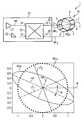
- Such a whole-body antennais schematically shown with a cage structure in FIG. 1 .
- the whole-body antenna 2 ′has antenna rods 7 ′ parallel to the longitudinal axis L and arranged at various circumferential positions around the examination tunnel T, which antenna rods 7 ′ are respectively connected by annular antenna elements 5 , 6 at the facing sides.
- the examination tunnelis thereby defined by the space enclosed by the antenna.
- FIG. 1shows the design of such a radio-frequency supply device that is most frequently used at present.
- a radio-frequency signal RFis emitted by a radio-frequency generator 21 which possesses a suitable radio-frequency amplifier at the output side.
- This radio-frequency signal RFis fed into a first input 24 of a signal splitter 23 .
- Said signal splitter 23is hereby what is known as a hybrid module that divides the radio-frequency signal RF into two partial signals RF 1 , RF 2 which are phase-shifted by 90° but are otherwise identical.
- These two partial signals RF 1 , RF 2are present at the outputs 26 , 27 of the signal splitter 23 and there are provided on the radio-frequency feed lines 28 , 29 to the connection points 3 , 4 of the whole-body antenna 2 ′.
- a fourth input 25 of the signal splitter 23is terminated with a 50 ⁇ resistor 22 in order to accommodate powers reflected by the whole-body antenna 2 ′.
- the antennais designed such that it emits a circularly polarized radio-frequency field, meaning that the antenna can emit in precisely one circularly polarized mode MCP (which is symbolically represented by the circular line in FIG. 1 ).
- Local field correctionscan be achieved by the use of dielectric cushions or similar elements influencing the RF field that are placed on the patient.
- FIG. 2A second possibility is shown in FIG. 2 .
- Thisis a design similar to the design in FIG. 1 , but respective amplitude and/or phase regulators 30 , 31 with which the amplitudes and/or phases of the partial signals RF 1 , RF 2 can be arbitrarily varied are additionally interposed after the outputs 26 , 27 of the signal splitter 23 in the radio-frequency feed lines 28 , 29 .
- Correspondingly modified partial signals RF 1 ′, RF 2 ′are fed into the whole-body antenna 2 ′ designed in the typical manner at the connection points 3 , 4 .
- Various radio-frequency modescan be excited in the whole-body antenna 2 ′ via a suitable phase and amplitude shift of the two partial signals RF 1 ′, RF 2 ′.
- a circularly polarized fieldis emitted as in the exemplary embodiment according to FIG. 1 .
- a disadvantage of this systemis that additional components 30 , 31 are required in order to affect the field in the desired manner. These components 30 , 31 must be highly precise. A corresponding control technology is additionally required in order to be able to control the components 30 , 31 as precisely as possible.
- An object of the present inventionis to provide a magnetic resonance system, an antenna system, a method for designing a magnetic resonance system and a method to generate magnetic resonance exposures with which an improved field distribution can be achieved with as little effort as possible in a whole-body antenna of the magnetic resonance system.
- the magnetic resonance system according to the inventionhas a conventional radio-frequency supply device in which the radio-frequency signal generated by a radio-frequency generator is divided in a typical signal splitter into two identical partial signals that are phase-shifted by 90° relative to one another and then are fed into the whole-body antenna at the two connection points of said whole-body antenna.
- the whole-body antennais deliberately fashioned so that it has such an intrinsic transmission characteristic that a radio-frequency field which is elliptically polarized in a defined manner in a plane lying perpendicular to the longitudinal axis (at least in the unloaded state of the examination tunnel) is emitted by the whole-body antenna due to the superimposition of the two partial signals that are shifted by 90° but are otherwise identical.
- an elliptical polarization in principleleads to a better B1 homogeneity in the patient. This is due to the fact that a circularly polarized field is normally elliptically distorted in the body of the patient due to the eddy currents. If an elliptically polarized field is thus emitted in an unloaded state of the examination tunnel (i.e. without a patient in the examination tunnel), it can be achieved—when the major axis of the ellipse is taken care of for a correspondingly suitable position—that the desired, homogenized radio-frequency field is achieved after the loading of the patent tunnel with a patient body.
- a corresponding antenna system for a magnetic resonance systemmust accordingly have a whole-body antenna according to the invention, with such an intrinsic transmission characteristic that, when two identical partial signals phase-shifted by 90° are fed into it at the two connection points, it emits a radio-frequency field which is elliptically polarized in a defined manner in a plane lying perpendicular to the longitudinal axis, at least in the unloaded state of the examination tunnel.
- a whole-body antennaextending like a cylinder around an examination tunnel along a longitudinal axis must be constructed. Furthermore, a radio-frequency generator for generation of a radio-frequency signal must be connected to a signal splitter which divides a radio-frequency signal arriving from the radio-frequency signal generator into two partial signals phase-shifted by 90° relative to one another which are output at two signal outputs of the signal splitter. A connection of the two signal outputs of the signal splitter must then ensue via two feed lines with two connection points at the whole-body antenna.
- the whole-body antennamust be designed so that it has the specific intrinsic transmission characteristic in order to emit a field elliptically polarized in a defined manner, at least in the unloaded state of the examination tunnel.
- a radio-frequency signalis divided into two partial signals that are identical but phase-shifted by 90°, and these partial signals are fed at two connection points into a whole-body antenna cylindrically extending around the examination tunnel along a longitudinal axis, which whole-body antenna thereupon emits a radio-frequency field.
- a previously cited whole-body antennais used, but it has an intrinsic transmission characteristic in order to emit an elliptically polarized field in an unloaded state of the examination tunnel.
- typical whole-body antennasare designed so that these emit an essentially (i.e. apart from typical, build-dependent tolerances) circularly polarized field given an infeed of identical signals phase-shifted by 90° at two connection points.
- the intrinsic transmission characteristic of the whole-body antenna according to the inventionis selected so that it emits an elliptically polarized radio-frequency field under these conditions.
- the antenna systemis thereby particularly preferably fashioned so that an elliptically polarized radio-frequency field forms in which the ratio of the major ellipse axis to the minor ellipse axis is approximately between 1.5 and 10, particularly preferably approximately between 2 and 5. This means that a distinctly elliptical form is preferred which does not deviate only slightly from a circle shape.
- the antenna systemcan be fashioned so that the elliptically polarized radio-frequency field possesses an arbitrary bearing.
- the antenna systemis particularly preferably fashioned so that an elliptically polarized radio-frequency field forms in which the major ellipse axis is tilted by an angle ⁇ relative to the horizontal. This means that the elliptically polarized radio-frequency field preferably lies diagonally in space.
- the antenna systemis fashioned so that—considered from the head of the examination tunnel—the angle by which the major ellipse axis is tilted clockwise relative to the horizontal lies inclusively between approximately 15° and approximately 70°, particularly preferably inclusively between approximately 22° and approximately 50°.
- the “service side” of the magnetic resonance scannerat which the connections to the additional components of the magnetic resonance system are normally located, is thereby viewed as the head of the examination tunnel. This is the side that is situated opposite the examination table feed side at which the examination table is driven into and out from the examination tunnel. That is typically also the side at which the head of the patient is located.
- the elliptically polarized radio-frequency fieldis in particular optimal for acquisitions of the abdominal region of the patient when the major ellipse axis lies in the cited angle range.
- connection pointsIn order to achieve an elliptically distorted radio-frequency field in the whole-body antenna, in principle it is sufficient to modify the connection points so that they do not lie below an angle of 90° relative to one another along the circumference of the antenna. If two partial signals that are phase-shifted by 90° relative to one another are then fed in at these connection points, a non-circularly polarized field already inevitably forms. On the other hand, an infeed of the partial signals at an angle ⁇ 90° leads in a typical antenna to an increased reflection at the antenna inputs. This increases the power loss.
- the antenna structureis therefore advantageously internally fashioned so that the desired elliptically polarized field arises.
- the whole-body antennatherefore advantageously possesses antenna elements annularly arranged distributed around the examination tunnel, and the whole-body antenna is thus fashioned and/or arranged relative to a radio-frequency shielding cylindrically surrounding the whole-body antenna such that at least two antenna elements located at different circumferential positions around the examination tunnel exhibit a different impedance.
- antenna elementsencompasses the most varied sub-components of the antenna, for example the conductor rods respectively running parallel to the longitudinal axis in a cage antenna or segments of the antenna ring elements respectively coupling the antenna rods with one another on the facing side in terms of radio-frequency.
- thesecan likewise be the conductor rods respectively running parallel to the longitudinal axis, which conductor rods are respectively, capacitively coupled at the ends with a radio-frequency shielding of the antenna system (instead of a connection via the ferrules) or, respectively the capacitive elements are coupled with the radio-frequency shielding to connect the antenna rods.
- an antenna elementpossesses a higher impedance, a smaller radio-frequency current flows through this antenna element. In contrast to this, a smaller impedance is associated with a higher radio-frequency current. Depending on the setting of the impedances of the various antenna elements, a different RF field distribution is thus generated.
- the impedance of the antenna elementscan vary due to the variation of the inductance and/or the capacitance and/or the ohmic resistance.
- a radio-frequency shielding that externally shields the radio-frequency antenna from the further components in the magnetic resonance scanneralso typically belongs to an antenna system with such a whole-body antenna. Not only the design of the individual antenna elements but also its position relative to the radio-frequency shielding has an influence on the impedances of the respective antenna elements.
- the radio-frequency shieldinglies at a fixed potential (typically at a ground potential), and the stray capacitances of the antenna elements relative to this potential are influenced by the distance of the antenna elements from the radio-frequency shielding.
- the inductance of the respective antenna elementis additionally reduced given a reduction of the distance of the antenna elements from the radio-frequency shielding.
- the whole-body antenna and the radio-frequency shieldingare therefore designed and arranged relative to one another so that a radial separation between the whole-body antenna and the radio-frequency shielding along the circumference changes.
- the whole-body antenna and/or the radio-frequency shieldingare fashioned such that they exhibit an elliptical cross-section in a plane lying perpendicular to the longitudinal axis.
- the radial distance between the whole-body antenna and the radio-frequency shieldingchanges along the circumference.
- the center axes of the whole-body antenna and of the radio-frequency shieldingare thereby arranged coaxially, as in conventional systems. It is also likewise possible that both the whole-body antenna and the radio-frequency shielding exhibit an elliptical cross-section.
- the whole-body antenna(for example a cage antenna or a band or, respectively, TEM antenna) advantageously has a number of antenna rods running parallel to the longitudinal axis, and at least two antenna rods located at different circumferential positions around the examination tunnel exhibit a different impedance.
- the whole-body antennacan have a cage structure in which the plurality of antenna rods running parallel to the longitudinal axis are coupled among one another by antenna ring elements, at least in terms of radio frequencies.
- These ring elementscan respectively be fashioned in circular shape but can also be elliptical.
- the couplingcan in principle be a solid conductor connection.
- theseare normally antenna ring elements that are composed of multiple ring segments capacitively coupled among one another that are respectively associated with the individual antenna rods.
- at least two antenna rodslocated at different circumferential positions around the examination tunnel and/or ring segments of the antenna ring elements, respectively exhibit by different impedances.
- the antennais fashioned so that at least two antenna rods located at different circumferential positions exhibit different conductor cross-sections.
- the antenna rodsare typically fashioned in the form of printed conductor traces that are directly applied on a conduit wall of the examination tunnel.
- the conductor tracesare of different widths, advantageously according to a specific pattern. Since, among other things, the conductor cross-section is representative of the inductance and thus the impedance of the respective antenna rods, a very simple variation of the impedances of the individual antenna rods is possible.
- the antenna rodscan consist of partial rods or, respectively, partial conductor traces that are respectively connected among one another with capacitors.
- the desired capacitance differencescan thus be achieved via insertion of different structural elements.
- Typical capacitance values of such antenna rodsare between 10 and 30 pF in a 3 Tesla whole-body antenna.
- specific antenna rodscan then be fashioned so that they exhibit 30 pF, in contrast to which others exhibit only 10 pF.
- the ring segmentscan likewise be coupled to the antenna ring elements with various capacitors along the circumference.
- different impedances of the individual antenna rodscan also be realized via different capacitors and/or inductors in the coupling of the antenna rods with the radio-frequency shielding, for example.
- two respective antenna elements located at opposite circumferential positionscan advantageously exhibit the same impedance (within the typical tolerances).
- two first antenna elements located at opposite circumferential positionscan exhibit a maximum impedance
- two antenna elements respectively located at 90° relative to the first antenna elementsexhibit a minimal impedance.
- the first antenna elements(which exhibit the maximum impedance) then define the direction of the major ellipse axis and the two second elements which exhibit the minimal impedance define the direction of the minor ellipse axis.
- the impedance of antenna elements respectively located between the first and second antenna elementslies between the impedances of said first and second antenna elements, and is respectively selected so that the impedance decreases from the first antenna elements to the second antenna elements.
- FIG. 1is a basic block diagram of the transmission system of a magnetic resonance system according to the prior art.
- FIG. 2is a basic block diagram of an expanded transmission system of a magnetic resonance system according to the prior art.
- FIG. 3is a basic block diagram of a first exemplary embodiment of a transmission system of a magnetic resonance system according to the invention.
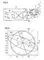
- FIG. 4is a diagram to explain the bearing of the ellipse of the elliptically polarized radio-frequency field.
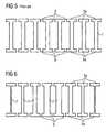
- FIG. 5is a schematic illustration of a winding of half of a 16-rod whole-body antenna according to the prior art.
- FIG. 6is a schematic illustration of an exemplary embodiment of half of a 16-rod whole-body antenna according to the invention.
- FIG. 7is a schematic cross-section perpendicular to the longitudinal direction of the antenna through an exemplary embodiment of an antenna system according to the invention, with a circular antenna and an elliptical radio-frequency shielding.
- FIG. 8is a schematic cross-section perpendicular to the longitudinal direction of the antenna through an exemplary embodiment of an antenna system according to the invention, with an elliptical antenna and a circular radio-frequency shielding.
- FIG. 9is a schematic cross-section perpendicular to the longitudinal direction of the antenna through an exemplary embodiment of an antenna system according to the invention, with an elliptical antenna and an elliptical radio-frequency shielding.
- FIGS. 1 and 2were already explained in detail above.
- the exemplary prior art embodiment according to FIG. 1is a typical, presently used whole-body antenna with a cage structure which is supplied by a typical radio-frequency supply device 20 .
- This radio-frequency supply device 20is fashioned so that the phase ratio between the partial signals RF 1 , RF 2 is established at exactly 90° and the amplitudes are identical within the scope of the typical tolerances. Only a circularly polarized radio-frequency field is ever emitted with this transmission system in the unloaded state of the whole-body antenna 2 ′.
- FIG. 2shows a more variable exemplary embodiment for a transmission system in which the ratio of the amplitudes and/or phases of the two partial signals RF 1 ′, RF 2 ′ can be freely adjusted relative to one another by means of amplitude and/or phase regulators 30 , 31 , whereby different transmission modes M CP , M EP can be emitted in the whole-body antenna 2 ′.
- FIG. 3now shows an exemplary embodiment for a transmission system of a magnetic resonance system 1 according to the invention.
- this magnetic resonance system 1naturally also includes all additional, typical components of a magnetic resonance system, for example a magnet system, a gradient system, an acquisition system, a controller, etc. These components are sufficiently known to the man skilled in the art and therefore do not need to be explained in detail here. They are thus also not shown in FIG. 1 for better clarity.
- a typical frequency supply device 20can be used as it is used in the exemplary embodiment according to FIG. 1 .
- the partial signals RF 1 , RF 2 arriving from the radio-frequency supply device 20 at the outputs 26 , 27 of the hybrid module 23 via the RF feed line 28 , 29are identical except for a fixed phase shift by 90°.
- a cage antenna 2 with a plurality of conductor rods 7 running parallel to the longitudinal axis L of the whole-body antenna 2 around an examination tunnel Tis used as an antenna 2 according the invention, which conductor rods 7 are respectively coupled among one another on the facing side by antenna ring elements 5 , 6 .
- Only eight conductor rods 7 of the antenna 2are shown in the schematic exemplary embodiment according to FIG. 3 .
- such a cage antennatypically possesses a higher number, for example sixteen or more conductor rods. Via suitable design measures it is ensured here that the whole-body antenna 2 has an intrinsic transmission characteristic so that an elliptically polarized field forms (i.e.
- the elliptically polarized transmission mode M EPis excited) although identical partial signals respectively phase-shifted by 90° are fed in at the typical connection points 3 , 4 that lie at 90° relative to one another on one of the antenna ring elements 5 .
- this mode M EPis shown so that the major axis of the ellipse is located parallel to the horizontal, i.e. parallel to the surface of the recumbent board on which the patient is borne and is moved into the examination tunnel T.
- FIG. 4is referenced for definition of an optimal bearing of the major axis HA of the elliptical polarization. Respectively plotted here is the bearing of the tip of the radio-frequency field vector rotating around the origin in the Cartesian coordinate system (the units of the coordinate axes are thereby arbitrarily selected).
- the circlehere characterizes the circularly polarized mode M CP which would be achieved in a normal antenna according to the prior art via the two partial signals fed in at 90° with a phase shift of 90°. The amplitude of the radio-frequency field thereby does not change over a revolution.
- the line LP 1represents the linearly polarized radio-frequency field which would be generated in the antenna by the partial RF signal fed in at the one connection point of the whole-body antenna
- the line LP 2represents the linearly polarized radio-frequency field which would be generated in the antenna by the partial RF signal fed in at the other connection point of the whole-body antenna.
- the circularly polarized mode M CParises via the superimposition of the two linearly polarized fields.
- the antenna 2is advantageously fashioned so that an elliptical transmission mode M EP is generated, meaning that the amplitude of the radio-frequency field changes over one revolution.
- the shape of the ellipseis determined by the ratio of the major axis HA and the minor axis NA. This ratio advantageously lies between 1.5 and 10, particularly preferably between 2 and 5.
- the elliptical transmission mode M EPis thereby preferably fashioned so that the major axis HA of the elliptically polarized field is tilted in the clockwise direction of the indicated horizontal H by an angle ⁇ between at least 15° and 70°, particularly preferably between 22° and 50°.
- the bearing shown in FIG. 4respectively applies from a consideration from the “service end” of the magnetic resonance scanner (i.e. from the head), which is opposite the end at which the examination table is driven into and out of the magnetic resonance scanner.
- FIG. 4The shape and bearing of the polarization ellipse that is required for an optimal homogeneity in the abdominal region of the patient is presented in FIG. 4 .
- the ratio of the major axis to minor axisis 3, and the tilt angle ⁇ is 22° relative to the horizontal.
- FIGS. 5 and 6A very simple possibility to realize a whole-body antenna with an intrinsic transmission characteristic for emission of an elliptically polarized field is now explained using FIGS. 5 and 6 .
- FIG. 5shows a winding of half of a 16-rod antenna according to the prior art.
- the individual conductor rods 7 ′(which are normally copper conductor traces applied on the outside of an examination tunnel tube) are all selected with the same width here.
- the individual conductor rods 7 ′are respectively connected at the ends with ring segments 5 a , 6 a running transversal to the conductor rods or, respectively, the conductor traces are fashioned so that these annular segments 5 a , 6 a respectively form T-shaped end pieces of the conductor rods 7 .
- Respective free spaces 8which are bridged by capacitor elements in order to capacitively couple the individual conductor rods 7 ′ with one another are located between the individual ring segments 5 a , 6 a .
- the antennais completely symmetrical and emits a circularly polarized field given the design presented in FIG. 1 .
- FIG. 6shows a simple variant to modify the transmission characteristic of the antenna 2 so that it emits an elliptically polarized field. It is hereby merely provided that the conductor rods 7 or copper conductor traces are fashioned with different widths. Due to the different conductor cross-sections, the individual conductor rods 7 have different inductances, which lead to a different current distribution to the individual antenna rods 7 . Additionally, the ohmic resistance is also altered by the different conductor trace widths (which plays a smaller role given radio-frequency signals, however). Alternatively or additionally, it can also be provided that the capacitances of the antenna rods 7 are different. Different capacitances between the individual ring segments 5 a , 6 a can likewise be provided. Since FIG. 6 shows only eight of the sixteen antenna rods of the whole-body antenna, it is clear that in a complete whole-body antenna the respective opposite antenna rods 7 exhibit the same width, and thus the same impedance.
- the separation of the impedancesis greatest between the antenna rods situated perpendicular to one another, and that the impedance continuously increases in steps among the antenna rods from rods with the most impedance (the two outermost antenna rods in FIG. 6 ) to antenna rods with the smallest impedance (the middle antenna rods in FIG. 6 ) in order to achieve a particularly uniform elliptical shape.
- FIGS. 7 , 8 and 9show three variants as to how an elliptically polarized field or a corresponding transmission characteristic of the whole-body antenna 2 of the antenna system can be achieved via suitable shape of the whole-body antenna 2 and a radio-frequency shielding surrounding the whole-body antenna 2 .
- This radio-frequency shielding 11is typically connected with a ground potential and provides for a shielding of the antenna 2 against the additional components situated outside of the antenna 2 in the magnetic resonance scanner.
- the inductance and stray capacitance of the whole-body antenna 2 or its individual antenna rods 7 relative to the radio-frequency shielding 11are also determined by the distance of said whole-body antenna 2 or, respectively, its individual antenna rods 7 from said radio-frequency shielding 11 .
- the radial distance r(i.e. the distance running in the radial direction between the antenna 2 and the radio-frequency shielding 11 ) also respectively influences the impedance in the appertaining part of the whole-body antenna 2 . If the radial distance r is relatively small, a high capacitance and a small inductance (and thus also a high impedance) of the antenna 2 are provided in this region. In contrast to this, if the distance r is relatively large, the stray capacitance is also low and the inductance (and thus the impedance) at this point is higher.
- FIG. 7thereby shows a first variant in which a typical whole-body antenna 2 with a circular cross-section is used and a slightly elliptical shape of the radio-frequency shielding 11 is selected.
- FIG. 8shows a variant in which a radio-frequency shielding 11 with a circular cross-section is used, however the whole-body antenna 2 has an elliptical cross-section.
- FIG. 9shows an exemplary embodiment in which both the whole-body antenna 2 and the radio-frequency shielding 11 possess an elliptical cross-section, wherein the major axes of the ellipses are tilted by 90° relative to one another.
- the bearing of the ellipses of the two components 2 , 11is shown in order to achieve a specific angle ⁇ between the major axis HA of the ellipse shape of the emitted, elliptically polarized radio-frequency field and the horizontal H, as this was explained using FIG. 4 .
- the preceding exemplary embodimentsshow how a whole-body antenna with an intrinsic transmission characteristic so that an elliptically polarized field is emitted can be realized with simple means.
- a field with improved B 1 homogeneitycan thus be achieved in a simple manner, wherein no additional hardware expenditure is necessary apart from the slight measures described above.
- these measuresare significantly more advantageous than the realization of two or more transmission channels, in particular of a corresponding number of transmission amplifiers. Retrofitting of existing systems can ensue via a simple exchange of the transmission antenna or the radio-frequency shielding.
Landscapes
- Physics & Mathematics (AREA)
- Condensed Matter Physics & Semiconductors (AREA)
- General Physics & Mathematics (AREA)
- Health & Medical Sciences (AREA)
- General Health & Medical Sciences (AREA)
- Nuclear Medicine, Radiotherapy & Molecular Imaging (AREA)
- Radiology & Medical Imaging (AREA)
- Engineering & Computer Science (AREA)
- Signal Processing (AREA)
- High Energy & Nuclear Physics (AREA)
- Magnetic Resonance Imaging Apparatus (AREA)
- Variable-Direction Aerials And Aerial Arrays (AREA)
Abstract
Description
Claims (19)
Applications Claiming Priority (2)
| Application Number | Priority Date | Filing Date | Title |
|---|---|---|---|
| DE102008006117ADE102008006117B4 (en) | 2008-01-25 | 2008-01-25 | Magnetic resonance system, antenna system, method for setting up a magnetic resonance system and method for generating magnetic resonance images |
| DE102008006117.4 | 2008-01-25 |
Publications (2)
| Publication Number | Publication Date |
|---|---|
| US20090192382A1 US20090192382A1 (en) | 2009-07-30 |
| US8362775B2true US8362775B2 (en) | 2013-01-29 |
Family
ID=40794416
Family Applications (1)
| Application Number | Title | Priority Date | Filing Date |
|---|---|---|---|
| US12/358,378Active2031-12-02US8362775B2 (en) | 2008-01-25 | 2009-01-23 | Magnetic resonance whole body antenna system, elliptically polarized with major ellipse axis tilted/non-horizontal at least when unoccupied by an examination subject |
Country Status (2)
| Country | Link |
|---|---|
| US (1) | US8362775B2 (en) |
| DE (1) | DE102008006117B4 (en) |
Cited By (118)
| Publication number | Priority date | Publication date | Assignee | Title |
|---|---|---|---|---|
| US20120176137A1 (en)* | 2009-09-30 | 2012-07-12 | Hitachi Medical Corporation | Gradient magnetic field coil and magnetic resonance imaging device |
| US9674711B2 (en) | 2013-11-06 | 2017-06-06 | At&T Intellectual Property I, L.P. | Surface-wave communications and methods thereof |
| US9685992B2 (en) | 2014-10-03 | 2017-06-20 | At&T Intellectual Property I, L.P. | Circuit panel network and methods thereof |
| US9705610B2 (en) | 2014-10-21 | 2017-07-11 | At&T Intellectual Property I, L.P. | Transmission device with impairment compensation and methods for use therewith |
| US9705561B2 (en) | 2015-04-24 | 2017-07-11 | At&T Intellectual Property I, L.P. | Directional coupling device and methods for use therewith |
| US9729197B2 (en) | 2015-10-01 | 2017-08-08 | At&T Intellectual Property I, L.P. | Method and apparatus for communicating network management traffic over a network |
| US9735833B2 (en) | 2015-07-31 | 2017-08-15 | At&T Intellectual Property I, L.P. | Method and apparatus for communications management in a neighborhood network |
| US9742462B2 (en) | 2014-12-04 | 2017-08-22 | At&T Intellectual Property I, L.P. | Transmission medium and communication interfaces and methods for use therewith |
| US9742521B2 (en) | 2014-11-20 | 2017-08-22 | At&T Intellectual Property I, L.P. | Transmission device with mode division multiplexing and methods for use therewith |
| US9749053B2 (en) | 2015-07-23 | 2017-08-29 | At&T Intellectual Property I, L.P. | Node device, repeater and methods for use therewith |
| US9748626B2 (en) | 2015-05-14 | 2017-08-29 | At&T Intellectual Property I, L.P. | Plurality of cables having different cross-sectional shapes which are bundled together to form a transmission medium |
| US9749013B2 (en) | 2015-03-17 | 2017-08-29 | At&T Intellectual Property I, L.P. | Method and apparatus for reducing attenuation of electromagnetic waves guided by a transmission medium |
| US9768833B2 (en) | 2014-09-15 | 2017-09-19 | At&T Intellectual Property I, L.P. | Method and apparatus for sensing a condition in a transmission medium of electromagnetic waves |
| US9769020B2 (en) | 2014-10-21 | 2017-09-19 | At&T Intellectual Property I, L.P. | Method and apparatus for responding to events affecting communications in a communication network |
| US9769128B2 (en) | 2015-09-28 | 2017-09-19 | At&T Intellectual Property I, L.P. | Method and apparatus for encryption of communications over a network |
| US9780834B2 (en) | 2014-10-21 | 2017-10-03 | At&T Intellectual Property I, L.P. | Method and apparatus for transmitting electromagnetic waves |
| US9787412B2 (en) | 2015-06-25 | 2017-10-10 | At&T Intellectual Property I, L.P. | Methods and apparatus for inducing a fundamental wave mode on a transmission medium |
| US9793954B2 (en) | 2015-04-28 | 2017-10-17 | At&T Intellectual Property I, L.P. | Magnetic coupling device and methods for use therewith |
| US9793955B2 (en) | 2015-04-24 | 2017-10-17 | At&T Intellectual Property I, Lp | Passive electrical coupling device and methods for use therewith |
| US9800327B2 (en) | 2014-11-20 | 2017-10-24 | At&T Intellectual Property I, L.P. | Apparatus for controlling operations of a communication device and methods thereof |
| US9820146B2 (en) | 2015-06-12 | 2017-11-14 | At&T Intellectual Property I, L.P. | Method and apparatus for authentication and identity management of communicating devices |
| US9838896B1 (en) | 2016-12-09 | 2017-12-05 | At&T Intellectual Property I, L.P. | Method and apparatus for assessing network coverage |
| US9838078B2 (en) | 2015-07-31 | 2017-12-05 | At&T Intellectual Property I, L.P. | Method and apparatus for exchanging communication signals |
| US9847850B2 (en) | 2014-10-14 | 2017-12-19 | At&T Intellectual Property I, L.P. | Method and apparatus for adjusting a mode of communication in a communication network |
| US9847566B2 (en) | 2015-07-14 | 2017-12-19 | At&T Intellectual Property I, L.P. | Method and apparatus for adjusting a field of a signal to mitigate interference |
| US9853342B2 (en) | 2015-07-14 | 2017-12-26 | At&T Intellectual Property I, L.P. | Dielectric transmission medium connector and methods for use therewith |
| US9860075B1 (en) | 2016-08-26 | 2018-01-02 | At&T Intellectual Property I, L.P. | Method and communication node for broadband distribution |
| US9865911B2 (en) | 2015-06-25 | 2018-01-09 | At&T Intellectual Property I, L.P. | Waveguide system for slot radiating first electromagnetic waves that are combined into a non-fundamental wave mode second electromagnetic wave on a transmission medium |
| US9866276B2 (en) | 2014-10-10 | 2018-01-09 | At&T Intellectual Property I, L.P. | Method and apparatus for arranging communication sessions in a communication system |
| US9866309B2 (en) | 2015-06-03 | 2018-01-09 | At&T Intellectual Property I, Lp | Host node device and methods for use therewith |
| US9871282B2 (en) | 2015-05-14 | 2018-01-16 | At&T Intellectual Property I, L.P. | At least one transmission medium having a dielectric surface that is covered at least in part by a second dielectric |
| US9871558B2 (en) | 2014-10-21 | 2018-01-16 | At&T Intellectual Property I, L.P. | Guided-wave transmission device and methods for use therewith |
| US9871283B2 (en) | 2015-07-23 | 2018-01-16 | At&T Intellectual Property I, Lp | Transmission medium having a dielectric core comprised of plural members connected by a ball and socket configuration |
| US9876571B2 (en) | 2015-02-20 | 2018-01-23 | At&T Intellectual Property I, Lp | Guided-wave transmission device with non-fundamental mode propagation and methods for use therewith |
| US9876605B1 (en) | 2016-10-21 | 2018-01-23 | At&T Intellectual Property I, L.P. | Launcher and coupling system to support desired guided wave mode |
| US9876264B2 (en) | 2015-10-02 | 2018-01-23 | At&T Intellectual Property I, Lp | Communication system, guided wave switch and methods for use therewith |
| US9882257B2 (en) | 2015-07-14 | 2018-01-30 | At&T Intellectual Property I, L.P. | Method and apparatus for launching a wave mode that mitigates interference |
| US9887447B2 (en) | 2015-05-14 | 2018-02-06 | At&T Intellectual Property I, L.P. | Transmission medium having multiple cores and methods for use therewith |
| US9893795B1 (en) | 2016-12-07 | 2018-02-13 | At&T Intellectual Property I, Lp | Method and repeater for broadband distribution |
| US9906269B2 (en) | 2014-09-17 | 2018-02-27 | At&T Intellectual Property I, L.P. | Monitoring and mitigating conditions in a communication network |
| US9904535B2 (en) | 2015-09-14 | 2018-02-27 | At&T Intellectual Property I, L.P. | Method and apparatus for distributing software |
| US9912027B2 (en) | 2015-07-23 | 2018-03-06 | At&T Intellectual Property I, L.P. | Method and apparatus for exchanging communication signals |
| US9912381B2 (en) | 2015-06-03 | 2018-03-06 | At&T Intellectual Property I, Lp | Network termination and methods for use therewith |
| US9913139B2 (en) | 2015-06-09 | 2018-03-06 | At&T Intellectual Property I, L.P. | Signal fingerprinting for authentication of communicating devices |
| US9912033B2 (en) | 2014-10-21 | 2018-03-06 | At&T Intellectual Property I, Lp | Guided wave coupler, coupling module and methods for use therewith |
| US9911020B1 (en) | 2016-12-08 | 2018-03-06 | At&T Intellectual Property I, L.P. | Method and apparatus for tracking via a radio frequency identification device |
| US9917341B2 (en) | 2015-05-27 | 2018-03-13 | At&T Intellectual Property I, L.P. | Apparatus and method for launching electromagnetic waves and for modifying radial dimensions of the propagating electromagnetic waves |
| US9927517B1 (en) | 2016-12-06 | 2018-03-27 | At&T Intellectual Property I, L.P. | Apparatus and methods for sensing rainfall |
| US9929755B2 (en) | 2015-07-14 | 2018-03-27 | At&T Intellectual Property I, L.P. | Method and apparatus for coupling an antenna to a device |
| US9948333B2 (en) | 2015-07-23 | 2018-04-17 | At&T Intellectual Property I, L.P. | Method and apparatus for wireless communications to mitigate interference |
| US9954287B2 (en) | 2014-11-20 | 2018-04-24 | At&T Intellectual Property I, L.P. | Apparatus for converting wireless signals and electromagnetic waves and methods thereof |
| US9954286B2 (en) | 2014-10-21 | 2018-04-24 | At&T Intellectual Property I, L.P. | Guided-wave transmission device with non-fundamental mode propagation and methods for use therewith |
| US9967173B2 (en) | 2015-07-31 | 2018-05-08 | At&T Intellectual Property I, L.P. | Method and apparatus for authentication and identity management of communicating devices |
| US9973416B2 (en) | 2014-10-02 | 2018-05-15 | At&T Intellectual Property I, L.P. | Method and apparatus that provides fault tolerance in a communication network |
| US9973940B1 (en) | 2017-02-27 | 2018-05-15 | At&T Intellectual Property I, L.P. | Apparatus and methods for dynamic impedance matching of a guided wave launcher |
| US9991580B2 (en) | 2016-10-21 | 2018-06-05 | At&T Intellectual Property I, L.P. | Launcher and coupling system for guided wave mode cancellation |
| US9998870B1 (en) | 2016-12-08 | 2018-06-12 | At&T Intellectual Property I, L.P. | Method and apparatus for proximity sensing |
| US9999038B2 (en) | 2013-05-31 | 2018-06-12 | At&T Intellectual Property I, L.P. | Remote distributed antenna system |
| US9997819B2 (en) | 2015-06-09 | 2018-06-12 | At&T Intellectual Property I, L.P. | Transmission medium and method for facilitating propagation of electromagnetic waves via a core |
| US10009067B2 (en) | 2014-12-04 | 2018-06-26 | At&T Intellectual Property I, L.P. | Method and apparatus for configuring a communication interface |
| US10020844B2 (en) | 2016-12-06 | 2018-07-10 | T&T Intellectual Property I, L.P. | Method and apparatus for broadcast communication via guided waves |
| US10027397B2 (en) | 2016-12-07 | 2018-07-17 | At&T Intellectual Property I, L.P. | Distributed antenna system and methods for use therewith |
| US10044409B2 (en) | 2015-07-14 | 2018-08-07 | At&T Intellectual Property I, L.P. | Transmission medium and methods for use therewith |
| US10051630B2 (en) | 2013-05-31 | 2018-08-14 | At&T Intellectual Property I, L.P. | Remote distributed antenna system |
| US10069185B2 (en) | 2015-06-25 | 2018-09-04 | At&T Intellectual Property I, L.P. | Methods and apparatus for inducing a non-fundamental wave mode on a transmission medium |
| US10069535B2 (en) | 2016-12-08 | 2018-09-04 | At&T Intellectual Property I, L.P. | Apparatus and methods for launching electromagnetic waves having a certain electric field structure |
| US10090594B2 (en) | 2016-11-23 | 2018-10-02 | At&T Intellectual Property I, L.P. | Antenna system having structural configurations for assembly |
| US10090606B2 (en) | 2015-07-15 | 2018-10-02 | At&T Intellectual Property I, L.P. | Antenna system with dielectric array and methods for use therewith |
| US10103422B2 (en) | 2016-12-08 | 2018-10-16 | At&T Intellectual Property I, L.P. | Method and apparatus for mounting network devices |
| US10135147B2 (en) | 2016-10-18 | 2018-11-20 | At&T Intellectual Property I, L.P. | Apparatus and methods for launching guided waves via an antenna |
| US10135145B2 (en) | 2016-12-06 | 2018-11-20 | At&T Intellectual Property I, L.P. | Apparatus and methods for generating an electromagnetic wave along a transmission medium |
| US10139820B2 (en) | 2016-12-07 | 2018-11-27 | At&T Intellectual Property I, L.P. | Method and apparatus for deploying equipment of a communication system |
| US10148016B2 (en) | 2015-07-14 | 2018-12-04 | At&T Intellectual Property I, L.P. | Apparatus and methods for communicating utilizing an antenna array |
| US10168695B2 (en) | 2016-12-07 | 2019-01-01 | At&T Intellectual Property I, L.P. | Method and apparatus for controlling an unmanned aircraft |
| US10178445B2 (en) | 2016-11-23 | 2019-01-08 | At&T Intellectual Property I, L.P. | Methods, devices, and systems for load balancing between a plurality of waveguides |
| US10205655B2 (en) | 2015-07-14 | 2019-02-12 | At&T Intellectual Property I, L.P. | Apparatus and methods for communicating utilizing an antenna array and multiple communication paths |
| US10224634B2 (en) | 2016-11-03 | 2019-03-05 | At&T Intellectual Property I, L.P. | Methods and apparatus for adjusting an operational characteristic of an antenna |
| US10225025B2 (en) | 2016-11-03 | 2019-03-05 | At&T Intellectual Property I, L.P. | Method and apparatus for detecting a fault in a communication system |
| US10243784B2 (en) | 2014-11-20 | 2019-03-26 | At&T Intellectual Property I, L.P. | System for generating topology information and methods thereof |
| US10243270B2 (en) | 2016-12-07 | 2019-03-26 | At&T Intellectual Property I, L.P. | Beam adaptive multi-feed dielectric antenna system and methods for use therewith |
| US10264586B2 (en) | 2016-12-09 | 2019-04-16 | At&T Mobility Ii Llc | Cloud-based packet controller and methods for use therewith |
| US10291334B2 (en) | 2016-11-03 | 2019-05-14 | At&T Intellectual Property I, L.P. | System for detecting a fault in a communication system |
| US10298293B2 (en) | 2017-03-13 | 2019-05-21 | At&T Intellectual Property I, L.P. | Apparatus of communication utilizing wireless network devices |
| US10305190B2 (en) | 2016-12-01 | 2019-05-28 | At&T Intellectual Property I, L.P. | Reflecting dielectric antenna system and methods for use therewith |
| US10312567B2 (en) | 2016-10-26 | 2019-06-04 | At&T Intellectual Property I, L.P. | Launcher with planar strip antenna and methods for use therewith |
| US10326494B2 (en) | 2016-12-06 | 2019-06-18 | At&T Intellectual Property I, L.P. | Apparatus for measurement de-embedding and methods for use therewith |
| US10326689B2 (en) | 2016-12-08 | 2019-06-18 | At&T Intellectual Property I, L.P. | Method and system for providing alternative communication paths |
| US10340983B2 (en) | 2016-12-09 | 2019-07-02 | At&T Intellectual Property I, L.P. | Method and apparatus for surveying remote sites via guided wave communications |
| US10340573B2 (en) | 2016-10-26 | 2019-07-02 | At&T Intellectual Property I, L.P. | Launcher with cylindrical coupling device and methods for use therewith |
| US10340601B2 (en) | 2016-11-23 | 2019-07-02 | At&T Intellectual Property I, L.P. | Multi-antenna system and methods for use therewith |
| US10340603B2 (en) | 2016-11-23 | 2019-07-02 | At&T Intellectual Property I, L.P. | Antenna system having shielded structural configurations for assembly |
| US10355367B2 (en) | 2015-10-16 | 2019-07-16 | At&T Intellectual Property I, L.P. | Antenna structure for exchanging wireless signals |
| US10359749B2 (en) | 2016-12-07 | 2019-07-23 | At&T Intellectual Property I, L.P. | Method and apparatus for utilities management via guided wave communication |
| US10361489B2 (en) | 2016-12-01 | 2019-07-23 | At&T Intellectual Property I, L.P. | Dielectric dish antenna system and methods for use therewith |
| US10374316B2 (en) | 2016-10-21 | 2019-08-06 | At&T Intellectual Property I, L.P. | System and dielectric antenna with non-uniform dielectric |
| US10382976B2 (en) | 2016-12-06 | 2019-08-13 | At&T Intellectual Property I, L.P. | Method and apparatus for managing wireless communications based on communication paths and network device positions |
| US10389037B2 (en) | 2016-12-08 | 2019-08-20 | At&T Intellectual Property I, L.P. | Apparatus and methods for selecting sections of an antenna array and use therewith |
| US10389029B2 (en) | 2016-12-07 | 2019-08-20 | At&T Intellectual Property I, L.P. | Multi-feed dielectric antenna system with core selection and methods for use therewith |
| EP3531156A1 (en) | 2018-02-21 | 2019-08-28 | Siemens Healthcare GmbH | Adjusting a field distribution of an antenna assembly of a magnetic resonance system |
| US10411356B2 (en) | 2016-12-08 | 2019-09-10 | At&T Intellectual Property I, L.P. | Apparatus and methods for selectively targeting communication devices with an antenna array |
| US10439675B2 (en) | 2016-12-06 | 2019-10-08 | At&T Intellectual Property I, L.P. | Method and apparatus for repeating guided wave communication signals |
| US10446936B2 (en) | 2016-12-07 | 2019-10-15 | At&T Intellectual Property I, L.P. | Multi-feed dielectric antenna system and methods for use therewith |
| US10498044B2 (en) | 2016-11-03 | 2019-12-03 | At&T Intellectual Property I, L.P. | Apparatus for configuring a surface of an antenna |
| US10530505B2 (en) | 2016-12-08 | 2020-01-07 | At&T Intellectual Property I, L.P. | Apparatus and methods for launching electromagnetic waves along a transmission medium |
| US10535928B2 (en) | 2016-11-23 | 2020-01-14 | At&T Intellectual Property I, L.P. | Antenna system and methods for use therewith |
| US10547348B2 (en) | 2016-12-07 | 2020-01-28 | At&T Intellectual Property I, L.P. | Method and apparatus for switching transmission mediums in a communication system |
| US10601494B2 (en) | 2016-12-08 | 2020-03-24 | At&T Intellectual Property I, L.P. | Dual-band communication device and method for use therewith |
| US10637149B2 (en) | 2016-12-06 | 2020-04-28 | At&T Intellectual Property I, L.P. | Injection molded dielectric antenna and methods for use therewith |
| US10650940B2 (en) | 2015-05-15 | 2020-05-12 | At&T Intellectual Property I, L.P. | Transmission medium having a conductive material and methods for use therewith |
| US10694379B2 (en) | 2016-12-06 | 2020-06-23 | At&T Intellectual Property I, L.P. | Waveguide system with device-based authentication and methods for use therewith |
| US10727599B2 (en) | 2016-12-06 | 2020-07-28 | At&T Intellectual Property I, L.P. | Launcher with slot antenna and methods for use therewith |
| US10755542B2 (en) | 2016-12-06 | 2020-08-25 | At&T Intellectual Property I, L.P. | Method and apparatus for surveillance via guided wave communication |
| US10777873B2 (en) | 2016-12-08 | 2020-09-15 | At&T Intellectual Property I, L.P. | Method and apparatus for mounting network devices |
| US10797781B2 (en) | 2015-06-03 | 2020-10-06 | At&T Intellectual Property I, L.P. | Client node device and methods for use therewith |
| US10811767B2 (en) | 2016-10-21 | 2020-10-20 | At&T Intellectual Property I, L.P. | System and dielectric antenna with convex dielectric radome |
| US10819035B2 (en) | 2016-12-06 | 2020-10-27 | At&T Intellectual Property I, L.P. | Launcher with helical antenna and methods for use therewith |
| US10916969B2 (en) | 2016-12-08 | 2021-02-09 | At&T Intellectual Property I, L.P. | Method and apparatus for providing power using an inductive coupling |
| US10938108B2 (en) | 2016-12-08 | 2021-03-02 | At&T Intellectual Property I, L.P. | Frequency selective multi-feed dielectric antenna system and methods for use therewith |
Families Citing this family (12)
| Publication number | Priority date | Publication date | Assignee | Title |
|---|---|---|---|---|
| DE102008005994B4 (en)* | 2008-01-24 | 2012-03-29 | Siemens Aktiengesellschaft | Arrangement for controlling an antenna arrangement |
| DE102008006117B4 (en)* | 2008-01-25 | 2013-12-12 | Siemens Aktiengesellschaft | Magnetic resonance system, antenna system, method for setting up a magnetic resonance system and method for generating magnetic resonance images |
| JP5685476B2 (en)* | 2011-04-11 | 2015-03-18 | 株式会社日立製作所 | Magnetic resonance imaging system |
| WO2012152618A1 (en) | 2011-05-06 | 2012-11-15 | Deutsches Krebsforschungszentrum | Antenna assembly for ultra-high field mri |
| RU2597068C2 (en)* | 2011-10-10 | 2016-09-10 | Конинклейке Филипс Н.В. | Transverse-electromagnetic (tem) radio-frequency coil for magnetic resonance |
| EP2620741A1 (en)* | 2012-01-24 | 2013-07-31 | Johann Hinken | Device for measuring coating thickness |
| DE102015202861B4 (en)* | 2015-02-17 | 2016-11-10 | Siemens Healthcare Gmbh | MR device with distribution network |
| EP3514561A1 (en) | 2018-01-18 | 2019-07-24 | Koninklijke Philips N.V. | Multi-channel magnetic resonance imaging rf coil |
| EP3527999B1 (en) | 2018-02-16 | 2024-03-27 | Siemens Healthineers AG | Transmitting antenna for a magnetic resonance device |
| US10884079B2 (en) | 2018-06-11 | 2021-01-05 | Children's Hospital Medical Center | Asymmetric birdcage coil for a magnetic resonance imaging (MRI) |
| US11275133B2 (en) | 2018-06-11 | 2022-03-15 | Children's Hospital Medical Center | Asymmetric birdcage coil |
| GB2600919A (en)* | 2020-11-04 | 2022-05-18 | Tesla Dynamic Coils BV | MRI systems and receive coil arrangements |
Citations (8)
| Publication number | Priority date | Publication date | Assignee | Title |
|---|---|---|---|---|
| US4766383A (en)* | 1987-02-24 | 1988-08-23 | Kabushiki Kaisha Toshiba | Quadrature antenna for magnetic resonance imaging using elliptical coils |
| US6806713B2 (en)* | 2002-10-15 | 2004-10-19 | Varian, Inc. | RF coil for magic angle spinning probe |
| US6885194B2 (en) | 2002-05-03 | 2005-04-26 | Ge Medical Systems Global Technology Company, Llc | Method and apparatus for minimizing gradient coil and rf coil coupling |
| US6900636B2 (en) | 2001-05-19 | 2005-05-31 | Koninklijke Philips Electronics N.V. | Transmission and receiving coil for MR apparatus |
| US7135864B1 (en)* | 2005-07-20 | 2006-11-14 | General Electric Company | System and method of elliptically driving an MRI Coil |
| US20090192382A1 (en)* | 2008-01-25 | 2009-07-30 | Juergen Nistler | Magnetic resonance system, antenna system, method for designing a magnetic resonance system and method to generate magnetic resonance exposures |
| US20090189609A1 (en)* | 2008-01-24 | 2009-07-30 | Ludwig Eberler | Apparatus for controlling an antenna arrangement |
| US20110118556A1 (en)* | 2009-11-13 | 2011-05-19 | Siegel Peter H | Systems and Methods for Diagnostics, Control and Treatment of Neurological Functions and Disorders by Exposure to Electromagnetic Waves |
Family Cites Families (1)
| Publication number | Priority date | Publication date | Assignee | Title |
|---|---|---|---|---|
| JP3372099B2 (en)* | 1994-02-14 | 2003-01-27 | 株式会社日立メディコ | RF probe |
- 2008
- 2008-01-25DEDE102008006117Apatent/DE102008006117B4/enactiveActive
- 2009
- 2009-01-23USUS12/358,378patent/US8362775B2/enactiveActive
Patent Citations (10)
| Publication number | Priority date | Publication date | Assignee | Title |
|---|---|---|---|---|
| US4766383A (en)* | 1987-02-24 | 1988-08-23 | Kabushiki Kaisha Toshiba | Quadrature antenna for magnetic resonance imaging using elliptical coils |
| US6900636B2 (en) | 2001-05-19 | 2005-05-31 | Koninklijke Philips Electronics N.V. | Transmission and receiving coil for MR apparatus |
| US6885194B2 (en) | 2002-05-03 | 2005-04-26 | Ge Medical Systems Global Technology Company, Llc | Method and apparatus for minimizing gradient coil and rf coil coupling |
| US7109712B2 (en) | 2002-05-03 | 2006-09-19 | Ge Medical Systems Global Technology Company, Llc | Method and apparatus for minimizing gradient coil and rf coil coupling |
| US6806713B2 (en)* | 2002-10-15 | 2004-10-19 | Varian, Inc. | RF coil for magic angle spinning probe |
| US7135864B1 (en)* | 2005-07-20 | 2006-11-14 | General Electric Company | System and method of elliptically driving an MRI Coil |
| US20090189609A1 (en)* | 2008-01-24 | 2009-07-30 | Ludwig Eberler | Apparatus for controlling an antenna arrangement |
| US7986142B2 (en)* | 2008-01-24 | 2011-07-26 | Siemens Aktiengesellschaft | Apparatus for controlling an MRI antenna arrangement with elliptical polarization and equal amplitude signals at feed points |
| US20090192382A1 (en)* | 2008-01-25 | 2009-07-30 | Juergen Nistler | Magnetic resonance system, antenna system, method for designing a magnetic resonance system and method to generate magnetic resonance exposures |
| US20110118556A1 (en)* | 2009-11-13 | 2011-05-19 | Siegel Peter H | Systems and Methods for Diagnostics, Control and Treatment of Neurological Functions and Disorders by Exposure to Electromagnetic Waves |
Non-Patent Citations (3)
| Title |
|---|
| Brock Haus Enzyklopädie (2006) vol. 13, p. 441. |
| Patent Abstracts of Japan Publication No. 07222729 A-Aug. 22, 1995. |
| Patent Abstracts of Japan Publication No. 07222729 A—Aug. 22, 1995. |
Cited By (134)
| Publication number | Priority date | Publication date | Assignee | Title |
|---|---|---|---|---|
| US9075119B2 (en)* | 2009-09-30 | 2015-07-07 | Hitachi Medical Corporation | Gradient magnetic field coil and magnetic resonance imaging device |
| US20120176137A1 (en)* | 2009-09-30 | 2012-07-12 | Hitachi Medical Corporation | Gradient magnetic field coil and magnetic resonance imaging device |
| US10051630B2 (en) | 2013-05-31 | 2018-08-14 | At&T Intellectual Property I, L.P. | Remote distributed antenna system |
| US9999038B2 (en) | 2013-05-31 | 2018-06-12 | At&T Intellectual Property I, L.P. | Remote distributed antenna system |
| US9674711B2 (en) | 2013-11-06 | 2017-06-06 | At&T Intellectual Property I, L.P. | Surface-wave communications and methods thereof |
| US9768833B2 (en) | 2014-09-15 | 2017-09-19 | At&T Intellectual Property I, L.P. | Method and apparatus for sensing a condition in a transmission medium of electromagnetic waves |
| US10063280B2 (en) | 2014-09-17 | 2018-08-28 | At&T Intellectual Property I, L.P. | Monitoring and mitigating conditions in a communication network |
| US9906269B2 (en) | 2014-09-17 | 2018-02-27 | At&T Intellectual Property I, L.P. | Monitoring and mitigating conditions in a communication network |
| US9973416B2 (en) | 2014-10-02 | 2018-05-15 | At&T Intellectual Property I, L.P. | Method and apparatus that provides fault tolerance in a communication network |
| US9685992B2 (en) | 2014-10-03 | 2017-06-20 | At&T Intellectual Property I, L.P. | Circuit panel network and methods thereof |
| US9866276B2 (en) | 2014-10-10 | 2018-01-09 | At&T Intellectual Property I, L.P. | Method and apparatus for arranging communication sessions in a communication system |
| US9847850B2 (en) | 2014-10-14 | 2017-12-19 | At&T Intellectual Property I, L.P. | Method and apparatus for adjusting a mode of communication in a communication network |
| US9876587B2 (en) | 2014-10-21 | 2018-01-23 | At&T Intellectual Property I, L.P. | Transmission device with impairment compensation and methods for use therewith |
| US9705610B2 (en) | 2014-10-21 | 2017-07-11 | At&T Intellectual Property I, L.P. | Transmission device with impairment compensation and methods for use therewith |
| US9769020B2 (en) | 2014-10-21 | 2017-09-19 | At&T Intellectual Property I, L.P. | Method and apparatus for responding to events affecting communications in a communication network |
| US9780834B2 (en) | 2014-10-21 | 2017-10-03 | At&T Intellectual Property I, L.P. | Method and apparatus for transmitting electromagnetic waves |
| US9912033B2 (en) | 2014-10-21 | 2018-03-06 | At&T Intellectual Property I, Lp | Guided wave coupler, coupling module and methods for use therewith |
| US9871558B2 (en) | 2014-10-21 | 2018-01-16 | At&T Intellectual Property I, L.P. | Guided-wave transmission device and methods for use therewith |
| US9960808B2 (en) | 2014-10-21 | 2018-05-01 | At&T Intellectual Property I, L.P. | Guided-wave transmission device and methods for use therewith |
| US9954286B2 (en) | 2014-10-21 | 2018-04-24 | At&T Intellectual Property I, L.P. | Guided-wave transmission device with non-fundamental mode propagation and methods for use therewith |
| US9954287B2 (en) | 2014-11-20 | 2018-04-24 | At&T Intellectual Property I, L.P. | Apparatus for converting wireless signals and electromagnetic waves and methods thereof |
| US9749083B2 (en) | 2014-11-20 | 2017-08-29 | At&T Intellectual Property I, L.P. | Transmission device with mode division multiplexing and methods for use therewith |
| US9742521B2 (en) | 2014-11-20 | 2017-08-22 | At&T Intellectual Property I, L.P. | Transmission device with mode division multiplexing and methods for use therewith |
| US9800327B2 (en) | 2014-11-20 | 2017-10-24 | At&T Intellectual Property I, L.P. | Apparatus for controlling operations of a communication device and methods thereof |
| US10243784B2 (en) | 2014-11-20 | 2019-03-26 | At&T Intellectual Property I, L.P. | System for generating topology information and methods thereof |
| US9742462B2 (en) | 2014-12-04 | 2017-08-22 | At&T Intellectual Property I, L.P. | Transmission medium and communication interfaces and methods for use therewith |
| US10009067B2 (en) | 2014-12-04 | 2018-06-26 | At&T Intellectual Property I, L.P. | Method and apparatus for configuring a communication interface |
| US9876570B2 (en) | 2015-02-20 | 2018-01-23 | At&T Intellectual Property I, Lp | Guided-wave transmission device with non-fundamental mode propagation and methods for use therewith |
| US9876571B2 (en) | 2015-02-20 | 2018-01-23 | At&T Intellectual Property I, Lp | Guided-wave transmission device with non-fundamental mode propagation and methods for use therewith |
| US9749013B2 (en) | 2015-03-17 | 2017-08-29 | At&T Intellectual Property I, L.P. | Method and apparatus for reducing attenuation of electromagnetic waves guided by a transmission medium |
| US9831912B2 (en) | 2015-04-24 | 2017-11-28 | At&T Intellectual Property I, Lp | Directional coupling device and methods for use therewith |
| US9793955B2 (en) | 2015-04-24 | 2017-10-17 | At&T Intellectual Property I, Lp | Passive electrical coupling device and methods for use therewith |
| US10224981B2 (en) | 2015-04-24 | 2019-03-05 | At&T Intellectual Property I, Lp | Passive electrical coupling device and methods for use therewith |
| US9705561B2 (en) | 2015-04-24 | 2017-07-11 | At&T Intellectual Property I, L.P. | Directional coupling device and methods for use therewith |
| US9793954B2 (en) | 2015-04-28 | 2017-10-17 | At&T Intellectual Property I, L.P. | Magnetic coupling device and methods for use therewith |
| US9748626B2 (en) | 2015-05-14 | 2017-08-29 | At&T Intellectual Property I, L.P. | Plurality of cables having different cross-sectional shapes which are bundled together to form a transmission medium |
| US9887447B2 (en) | 2015-05-14 | 2018-02-06 | At&T Intellectual Property I, L.P. | Transmission medium having multiple cores and methods for use therewith |
| US9871282B2 (en) | 2015-05-14 | 2018-01-16 | At&T Intellectual Property I, L.P. | At least one transmission medium having a dielectric surface that is covered at least in part by a second dielectric |
| US10650940B2 (en) | 2015-05-15 | 2020-05-12 | At&T Intellectual Property I, L.P. | Transmission medium having a conductive material and methods for use therewith |
| US9917341B2 (en) | 2015-05-27 | 2018-03-13 | At&T Intellectual Property I, L.P. | Apparatus and method for launching electromagnetic waves and for modifying radial dimensions of the propagating electromagnetic waves |
| US10050697B2 (en) | 2015-06-03 | 2018-08-14 | At&T Intellectual Property I, L.P. | Host node device and methods for use therewith |
| US9912382B2 (en) | 2015-06-03 | 2018-03-06 | At&T Intellectual Property I, Lp | Network termination and methods for use therewith |
| US10797781B2 (en) | 2015-06-03 | 2020-10-06 | At&T Intellectual Property I, L.P. | Client node device and methods for use therewith |
| US9935703B2 (en) | 2015-06-03 | 2018-04-03 | At&T Intellectual Property I, L.P. | Host node device and methods for use therewith |
| US9866309B2 (en) | 2015-06-03 | 2018-01-09 | At&T Intellectual Property I, Lp | Host node device and methods for use therewith |
| US10812174B2 (en) | 2015-06-03 | 2020-10-20 | At&T Intellectual Property I, L.P. | Client node device and methods for use therewith |
| US9967002B2 (en) | 2015-06-03 | 2018-05-08 | At&T Intellectual I, Lp | Network termination and methods for use therewith |
| US9912381B2 (en) | 2015-06-03 | 2018-03-06 | At&T Intellectual Property I, Lp | Network termination and methods for use therewith |
| US9913139B2 (en) | 2015-06-09 | 2018-03-06 | At&T Intellectual Property I, L.P. | Signal fingerprinting for authentication of communicating devices |
| US9997819B2 (en) | 2015-06-09 | 2018-06-12 | At&T Intellectual Property I, L.P. | Transmission medium and method for facilitating propagation of electromagnetic waves via a core |
| US9820146B2 (en) | 2015-06-12 | 2017-11-14 | At&T Intellectual Property I, L.P. | Method and apparatus for authentication and identity management of communicating devices |
| US9787412B2 (en) | 2015-06-25 | 2017-10-10 | At&T Intellectual Property I, L.P. | Methods and apparatus for inducing a fundamental wave mode on a transmission medium |
| US9865911B2 (en) | 2015-06-25 | 2018-01-09 | At&T Intellectual Property I, L.P. | Waveguide system for slot radiating first electromagnetic waves that are combined into a non-fundamental wave mode second electromagnetic wave on a transmission medium |
| US10069185B2 (en) | 2015-06-25 | 2018-09-04 | At&T Intellectual Property I, L.P. | Methods and apparatus for inducing a non-fundamental wave mode on a transmission medium |
| US9929755B2 (en) | 2015-07-14 | 2018-03-27 | At&T Intellectual Property I, L.P. | Method and apparatus for coupling an antenna to a device |
| US10044409B2 (en) | 2015-07-14 | 2018-08-07 | At&T Intellectual Property I, L.P. | Transmission medium and methods for use therewith |
| US10148016B2 (en) | 2015-07-14 | 2018-12-04 | At&T Intellectual Property I, L.P. | Apparatus and methods for communicating utilizing an antenna array |
| US9847566B2 (en) | 2015-07-14 | 2017-12-19 | At&T Intellectual Property I, L.P. | Method and apparatus for adjusting a field of a signal to mitigate interference |
| US9882257B2 (en) | 2015-07-14 | 2018-01-30 | At&T Intellectual Property I, L.P. | Method and apparatus for launching a wave mode that mitigates interference |
| US10205655B2 (en) | 2015-07-14 | 2019-02-12 | At&T Intellectual Property I, L.P. | Apparatus and methods for communicating utilizing an antenna array and multiple communication paths |
| US9853342B2 (en) | 2015-07-14 | 2017-12-26 | At&T Intellectual Property I, L.P. | Dielectric transmission medium connector and methods for use therewith |
| US10090606B2 (en) | 2015-07-15 | 2018-10-02 | At&T Intellectual Property I, L.P. | Antenna system with dielectric array and methods for use therewith |
| US9806818B2 (en) | 2015-07-23 | 2017-10-31 | At&T Intellectual Property I, Lp | Node device, repeater and methods for use therewith |
| US9912027B2 (en) | 2015-07-23 | 2018-03-06 | At&T Intellectual Property I, L.P. | Method and apparatus for exchanging communication signals |
| US9871283B2 (en) | 2015-07-23 | 2018-01-16 | At&T Intellectual Property I, Lp | Transmission medium having a dielectric core comprised of plural members connected by a ball and socket configuration |
| US9948333B2 (en) | 2015-07-23 | 2018-04-17 | At&T Intellectual Property I, L.P. | Method and apparatus for wireless communications to mitigate interference |
| US9749053B2 (en) | 2015-07-23 | 2017-08-29 | At&T Intellectual Property I, L.P. | Node device, repeater and methods for use therewith |
| US9838078B2 (en) | 2015-07-31 | 2017-12-05 | At&T Intellectual Property I, L.P. | Method and apparatus for exchanging communication signals |
| US9967173B2 (en) | 2015-07-31 | 2018-05-08 | At&T Intellectual Property I, L.P. | Method and apparatus for authentication and identity management of communicating devices |
| US9735833B2 (en) | 2015-07-31 | 2017-08-15 | At&T Intellectual Property I, L.P. | Method and apparatus for communications management in a neighborhood network |
| US9904535B2 (en) | 2015-09-14 | 2018-02-27 | At&T Intellectual Property I, L.P. | Method and apparatus for distributing software |
| US9769128B2 (en) | 2015-09-28 | 2017-09-19 | At&T Intellectual Property I, L.P. | Method and apparatus for encryption of communications over a network |
| US9729197B2 (en) | 2015-10-01 | 2017-08-08 | At&T Intellectual Property I, L.P. | Method and apparatus for communicating network management traffic over a network |
| US9876264B2 (en) | 2015-10-02 | 2018-01-23 | At&T Intellectual Property I, Lp | Communication system, guided wave switch and methods for use therewith |
| US10355367B2 (en) | 2015-10-16 | 2019-07-16 | At&T Intellectual Property I, L.P. | Antenna structure for exchanging wireless signals |
| US9860075B1 (en) | 2016-08-26 | 2018-01-02 | At&T Intellectual Property I, L.P. | Method and communication node for broadband distribution |
| US10135147B2 (en) | 2016-10-18 | 2018-11-20 | At&T Intellectual Property I, L.P. | Apparatus and methods for launching guided waves via an antenna |
| US9991580B2 (en) | 2016-10-21 | 2018-06-05 | At&T Intellectual Property I, L.P. | Launcher and coupling system for guided wave mode cancellation |
| US10374316B2 (en) | 2016-10-21 | 2019-08-06 | At&T Intellectual Property I, L.P. | System and dielectric antenna with non-uniform dielectric |
| US10811767B2 (en) | 2016-10-21 | 2020-10-20 | At&T Intellectual Property I, L.P. | System and dielectric antenna with convex dielectric radome |
| US9876605B1 (en) | 2016-10-21 | 2018-01-23 | At&T Intellectual Property I, L.P. | Launcher and coupling system to support desired guided wave mode |
| US10312567B2 (en) | 2016-10-26 | 2019-06-04 | At&T Intellectual Property I, L.P. | Launcher with planar strip antenna and methods for use therewith |
| US10340573B2 (en) | 2016-10-26 | 2019-07-02 | At&T Intellectual Property I, L.P. | Launcher with cylindrical coupling device and methods for use therewith |
| US10498044B2 (en) | 2016-11-03 | 2019-12-03 | At&T Intellectual Property I, L.P. | Apparatus for configuring a surface of an antenna |
| US10225025B2 (en) | 2016-11-03 | 2019-03-05 | At&T Intellectual Property I, L.P. | Method and apparatus for detecting a fault in a communication system |
| US10224634B2 (en) | 2016-11-03 | 2019-03-05 | At&T Intellectual Property I, L.P. | Methods and apparatus for adjusting an operational characteristic of an antenna |
| US10291334B2 (en) | 2016-11-03 | 2019-05-14 | At&T Intellectual Property I, L.P. | System for detecting a fault in a communication system |
| US10178445B2 (en) | 2016-11-23 | 2019-01-08 | At&T Intellectual Property I, L.P. | Methods, devices, and systems for load balancing between a plurality of waveguides |
| US10340601B2 (en) | 2016-11-23 | 2019-07-02 | At&T Intellectual Property I, L.P. | Multi-antenna system and methods for use therewith |
| US10340603B2 (en) | 2016-11-23 | 2019-07-02 | At&T Intellectual Property I, L.P. | Antenna system having shielded structural configurations for assembly |
| US10090594B2 (en) | 2016-11-23 | 2018-10-02 | At&T Intellectual Property I, L.P. | Antenna system having structural configurations for assembly |
| US10535928B2 (en) | 2016-11-23 | 2020-01-14 | At&T Intellectual Property I, L.P. | Antenna system and methods for use therewith |
| US10361489B2 (en) | 2016-12-01 | 2019-07-23 | At&T Intellectual Property I, L.P. | Dielectric dish antenna system and methods for use therewith |
| US10305190B2 (en) | 2016-12-01 | 2019-05-28 | At&T Intellectual Property I, L.P. | Reflecting dielectric antenna system and methods for use therewith |
| US10020844B2 (en) | 2016-12-06 | 2018-07-10 | T&T Intellectual Property I, L.P. | Method and apparatus for broadcast communication via guided waves |
| US9927517B1 (en) | 2016-12-06 | 2018-03-27 | At&T Intellectual Property I, L.P. | Apparatus and methods for sensing rainfall |
| US10637149B2 (en) | 2016-12-06 | 2020-04-28 | At&T Intellectual Property I, L.P. | Injection molded dielectric antenna and methods for use therewith |
| US10694379B2 (en) | 2016-12-06 | 2020-06-23 | At&T Intellectual Property I, L.P. | Waveguide system with device-based authentication and methods for use therewith |
| US10326494B2 (en) | 2016-12-06 | 2019-06-18 | At&T Intellectual Property I, L.P. | Apparatus for measurement de-embedding and methods for use therewith |
| US10439675B2 (en) | 2016-12-06 | 2019-10-08 | At&T Intellectual Property I, L.P. | Method and apparatus for repeating guided wave communication signals |
| US10382976B2 (en) | 2016-12-06 | 2019-08-13 | At&T Intellectual Property I, L.P. | Method and apparatus for managing wireless communications based on communication paths and network device positions |
| US10727599B2 (en) | 2016-12-06 | 2020-07-28 | At&T Intellectual Property I, L.P. | Launcher with slot antenna and methods for use therewith |
| US10755542B2 (en) | 2016-12-06 | 2020-08-25 | At&T Intellectual Property I, L.P. | Method and apparatus for surveillance via guided wave communication |
| US10135145B2 (en) | 2016-12-06 | 2018-11-20 | At&T Intellectual Property I, L.P. | Apparatus and methods for generating an electromagnetic wave along a transmission medium |
| US10819035B2 (en) | 2016-12-06 | 2020-10-27 | At&T Intellectual Property I, L.P. | Launcher with helical antenna and methods for use therewith |
| US10243270B2 (en) | 2016-12-07 | 2019-03-26 | At&T Intellectual Property I, L.P. | Beam adaptive multi-feed dielectric antenna system and methods for use therewith |
| US10446936B2 (en) | 2016-12-07 | 2019-10-15 | At&T Intellectual Property I, L.P. | Multi-feed dielectric antenna system and methods for use therewith |
| US10027397B2 (en) | 2016-12-07 | 2018-07-17 | At&T Intellectual Property I, L.P. | Distributed antenna system and methods for use therewith |
| US10139820B2 (en) | 2016-12-07 | 2018-11-27 | At&T Intellectual Property I, L.P. | Method and apparatus for deploying equipment of a communication system |
| US10168695B2 (en) | 2016-12-07 | 2019-01-01 | At&T Intellectual Property I, L.P. | Method and apparatus for controlling an unmanned aircraft |
| US10389029B2 (en) | 2016-12-07 | 2019-08-20 | At&T Intellectual Property I, L.P. | Multi-feed dielectric antenna system with core selection and methods for use therewith |
| US9893795B1 (en) | 2016-12-07 | 2018-02-13 | At&T Intellectual Property I, Lp | Method and repeater for broadband distribution |
| US10547348B2 (en) | 2016-12-07 | 2020-01-28 | At&T Intellectual Property I, L.P. | Method and apparatus for switching transmission mediums in a communication system |
| US10359749B2 (en) | 2016-12-07 | 2019-07-23 | At&T Intellectual Property I, L.P. | Method and apparatus for utilities management via guided wave communication |
| US10326689B2 (en) | 2016-12-08 | 2019-06-18 | At&T Intellectual Property I, L.P. | Method and system for providing alternative communication paths |
| US10389037B2 (en) | 2016-12-08 | 2019-08-20 | At&T Intellectual Property I, L.P. | Apparatus and methods for selecting sections of an antenna array and use therewith |
| US10530505B2 (en) | 2016-12-08 | 2020-01-07 | At&T Intellectual Property I, L.P. | Apparatus and methods for launching electromagnetic waves along a transmission medium |
| US10938108B2 (en) | 2016-12-08 | 2021-03-02 | At&T Intellectual Property I, L.P. | Frequency selective multi-feed dielectric antenna system and methods for use therewith |
| US10411356B2 (en) | 2016-12-08 | 2019-09-10 | At&T Intellectual Property I, L.P. | Apparatus and methods for selectively targeting communication devices with an antenna array |
| US10601494B2 (en) | 2016-12-08 | 2020-03-24 | At&T Intellectual Property I, L.P. | Dual-band communication device and method for use therewith |
| US10916969B2 (en) | 2016-12-08 | 2021-02-09 | At&T Intellectual Property I, L.P. | Method and apparatus for providing power using an inductive coupling |
| US10069535B2 (en) | 2016-12-08 | 2018-09-04 | At&T Intellectual Property I, L.P. | Apparatus and methods for launching electromagnetic waves having a certain electric field structure |
| US9998870B1 (en) | 2016-12-08 | 2018-06-12 | At&T Intellectual Property I, L.P. | Method and apparatus for proximity sensing |
| US10811781B2 (en) | 2016-12-08 | 2020-10-20 | At&T Intellectual Property I, L.P. | Apparatus and methods for selecting sections of an antenna array and use therewith |
| US10103422B2 (en) | 2016-12-08 | 2018-10-16 | At&T Intellectual Property I, L.P. | Method and apparatus for mounting network devices |
| US9911020B1 (en) | 2016-12-08 | 2018-03-06 | At&T Intellectual Property I, L.P. | Method and apparatus for tracking via a radio frequency identification device |
| US10777873B2 (en) | 2016-12-08 | 2020-09-15 | At&T Intellectual Property I, L.P. | Method and apparatus for mounting network devices |
| US9838896B1 (en) | 2016-12-09 | 2017-12-05 | At&T Intellectual Property I, L.P. | Method and apparatus for assessing network coverage |
| US10340983B2 (en) | 2016-12-09 | 2019-07-02 | At&T Intellectual Property I, L.P. | Method and apparatus for surveying remote sites via guided wave communications |
| US10264586B2 (en) | 2016-12-09 | 2019-04-16 | At&T Mobility Ii Llc | Cloud-based packet controller and methods for use therewith |
| US9973940B1 (en) | 2017-02-27 | 2018-05-15 | At&T Intellectual Property I, L.P. | Apparatus and methods for dynamic impedance matching of a guided wave launcher |
| US10298293B2 (en) | 2017-03-13 | 2019-05-21 | At&T Intellectual Property I, L.P. | Apparatus of communication utilizing wireless network devices |
| US10761160B2 (en) | 2018-02-21 | 2020-09-01 | Siemens Healthcare Gmbh | Adjusting a field distribution of an antenna arrangement of a magnetic resonance system |
| EP3531156A1 (en) | 2018-02-21 | 2019-08-28 | Siemens Healthcare GmbH | Adjusting a field distribution of an antenna assembly of a magnetic resonance system |
Also Published As
| Publication number | Publication date |
|---|---|
| US20090192382A1 (en) | 2009-07-30 |
| DE102008006117A1 (en) | 2009-07-30 |
| DE102008006117B4 (en) | 2013-12-12 |
Similar Documents
| Publication | Publication Date | Title |
|---|---|---|
| US8362775B2 (en) | Magnetic resonance whole body antenna system, elliptically polarized with major ellipse axis tilted/non-horizontal at least when unoccupied by an examination subject | |
| US9274189B2 (en) | High-frequency coil unit and magnetic resonance imaging device | |
| US9983279B2 (en) | Radio frequency (RF) birdcage coil with separately controlled ring members and rungs for use in a magnetic resonance (MR) imaging system | |
| JP5368641B2 (en) | High frequency coil and magnetic resonance imaging apparatus using the same | |
| US9759788B2 (en) | Magnetic resonance coil, device and system | |
| US9541614B2 (en) | High frequency coil unit and magnetic resonance imaging apparatus | |
| US8193810B2 (en) | MRI apparatus with RF surface coil having at least three resonance frequencies | |
| JP6402112B2 (en) | Z-segmented radio frequency antenna apparatus for magnetic resonance imaging | |
| US20050134271A1 (en) | Phased array knee coil | |
| US7791344B2 (en) | Magnetic resonance RF transmission system and MR system and method using same | |
| JP2020501808A (en) | RF coil device and RF shielding device for different MRI modes | |
| US11112471B2 (en) | Inductively feeding an RF coil for magnetic resonance imaging | |
| US10241163B2 (en) | TEM resonator system especially for use in an MRI system | |
| US8358132B2 (en) | Irradiating coil and magnetic resonance imaging apparatus using the same | |
| US7683622B2 (en) | Radio-frequency transmission arrangement for a magnetic resonance system | |
| US7688070B2 (en) | Elevated endring birdcage antenna for MRI applications | |
| US9971001B2 (en) | Volume array coil with enforced uniform element currents for improved excitation homogeneity | |
| JP4350889B2 (en) | High frequency coil and magnetic resonance imaging apparatus | |
| JPH11309128A (en) | Magnetic resonance imaging device |
Legal Events
| Date | Code | Title | Description |
|---|---|---|---|
| AS | Assignment | Owner name:SIEMENS AKTIENGESELLSCHAFT, GERMANY Free format text:ASSIGNMENT OF ASSIGNORS INTEREST;ASSIGNORS:NISTLER, JUERGEN;RENZ, WOLFGANG;SPECKNER, THORSTEN;REEL/FRAME:022497/0139 Effective date:20090302 | |
| STCF | Information on status: patent grant | Free format text:PATENTED CASE | |
| FPAY | Fee payment | Year of fee payment:4 | |
| AS | Assignment | Owner name:SIEMENS HEALTHCARE GMBH, GERMANY Free format text:ASSIGNMENT OF ASSIGNORS INTEREST;ASSIGNOR:SIEMENS AKTIENGESELLSCHAFT;REEL/FRAME:039271/0561 Effective date:20160610 | |
| MAFP | Maintenance fee payment | Free format text:PAYMENT OF MAINTENANCE FEE, 8TH YEAR, LARGE ENTITY (ORIGINAL EVENT CODE: M1552); ENTITY STATUS OF PATENT OWNER: LARGE ENTITY Year of fee payment:8 | |
| AS | Assignment | Owner name:SIEMENS HEALTHINEERS AG, GERMANY Free format text:ASSIGNMENT OF ASSIGNORS INTEREST;ASSIGNOR:SIEMENS HEALTHCARE GMBH;REEL/FRAME:066088/0256 Effective date:20231219 | |
| AS | Assignment | Owner name:SIEMENS HEALTHINEERS AG, GERMANY Free format text:CORRECTIVE ASSIGNMENT TO CORRECT THE ASSIGNEE PREVIOUSLY RECORDED AT REEL: 066088 FRAME: 0256. ASSIGNOR(S) HEREBY CONFIRMS THE ASSIGNMENT;ASSIGNOR:SIEMENS HEALTHCARE GMBH;REEL/FRAME:071178/0246 Effective date:20231219 | |
| MAFP | Maintenance fee payment | Free format text:PAYMENT OF MAINTENANCE FEE, 12TH YEAR, LARGE ENTITY (ORIGINAL EVENT CODE: M1553); ENTITY STATUS OF PATENT OWNER: LARGE ENTITY Year of fee payment:12 |