US8361156B2 - Systems and methods for spinal fusion - Google Patents
Systems and methods for spinal fusionDownload PDFInfo
- Publication number
- US8361156B2 US8361156B2US13/441,092US201213441092AUS8361156B2US 8361156 B2US8361156 B2US 8361156B2US 201213441092 AUS201213441092 AUS 201213441092AUS 8361156 B2US8361156 B2US 8361156B2
- Authority
- US
- United States
- Prior art keywords
- implant
- spinal fusion
- fusion implant
- aperture
- sidewall
- Prior art date
- Legal status (The legal status is an assumption and is not a legal conclusion. Google has not performed a legal analysis and makes no representation as to the accuracy of the status listed.)
- Expired - Lifetime
Links
Images


Classifications
- A—HUMAN NECESSITIES
- A61—MEDICAL OR VETERINARY SCIENCE; HYGIENE
- A61F—FILTERS IMPLANTABLE INTO BLOOD VESSELS; PROSTHESES; DEVICES PROVIDING PATENCY TO, OR PREVENTING COLLAPSING OF, TUBULAR STRUCTURES OF THE BODY, e.g. STENTS; ORTHOPAEDIC, NURSING OR CONTRACEPTIVE DEVICES; FOMENTATION; TREATMENT OR PROTECTION OF EYES OR EARS; BANDAGES, DRESSINGS OR ABSORBENT PADS; FIRST-AID KITS
- A61F2/00—Filters implantable into blood vessels; Prostheses, i.e. artificial substitutes or replacements for parts of the body; Appliances for connecting them with the body; Devices providing patency to, or preventing collapsing of, tubular structures of the body, e.g. stents
- A61F2/02—Prostheses implantable into the body
- A61F2/30—Joints
- A61F2/44—Joints for the spine, e.g. vertebrae, spinal discs
- A61F2/4455—Joints for the spine, e.g. vertebrae, spinal discs for the fusion of spinal bodies, e.g. intervertebral fusion of adjacent spinal bodies, e.g. fusion cages
- A61F2/447—Joints for the spine, e.g. vertebrae, spinal discs for the fusion of spinal bodies, e.g. intervertebral fusion of adjacent spinal bodies, e.g. fusion cages substantially parallelepipedal, e.g. having a rectangular or trapezoidal cross-section
- A—HUMAN NECESSITIES
- A61—MEDICAL OR VETERINARY SCIENCE; HYGIENE
- A61F—FILTERS IMPLANTABLE INTO BLOOD VESSELS; PROSTHESES; DEVICES PROVIDING PATENCY TO, OR PREVENTING COLLAPSING OF, TUBULAR STRUCTURES OF THE BODY, e.g. STENTS; ORTHOPAEDIC, NURSING OR CONTRACEPTIVE DEVICES; FOMENTATION; TREATMENT OR PROTECTION OF EYES OR EARS; BANDAGES, DRESSINGS OR ABSORBENT PADS; FIRST-AID KITS
- A61F2/00—Filters implantable into blood vessels; Prostheses, i.e. artificial substitutes or replacements for parts of the body; Appliances for connecting them with the body; Devices providing patency to, or preventing collapsing of, tubular structures of the body, e.g. stents
- A61F2/02—Prostheses implantable into the body
- A61F2/30—Joints
- A61F2/30767—Special external or bone-contacting surface, e.g. coating for improving bone ingrowth
- A—HUMAN NECESSITIES
- A61—MEDICAL OR VETERINARY SCIENCE; HYGIENE
- A61F—FILTERS IMPLANTABLE INTO BLOOD VESSELS; PROSTHESES; DEVICES PROVIDING PATENCY TO, OR PREVENTING COLLAPSING OF, TUBULAR STRUCTURES OF THE BODY, e.g. STENTS; ORTHOPAEDIC, NURSING OR CONTRACEPTIVE DEVICES; FOMENTATION; TREATMENT OR PROTECTION OF EYES OR EARS; BANDAGES, DRESSINGS OR ABSORBENT PADS; FIRST-AID KITS
- A61F2/00—Filters implantable into blood vessels; Prostheses, i.e. artificial substitutes or replacements for parts of the body; Appliances for connecting them with the body; Devices providing patency to, or preventing collapsing of, tubular structures of the body, e.g. stents
- A61F2/02—Prostheses implantable into the body
- A61F2/30—Joints
- A61F2/44—Joints for the spine, e.g. vertebrae, spinal discs
- A61F2/442—Intervertebral or spinal discs, e.g. resilient
- A—HUMAN NECESSITIES
- A61—MEDICAL OR VETERINARY SCIENCE; HYGIENE
- A61F—FILTERS IMPLANTABLE INTO BLOOD VESSELS; PROSTHESES; DEVICES PROVIDING PATENCY TO, OR PREVENTING COLLAPSING OF, TUBULAR STRUCTURES OF THE BODY, e.g. STENTS; ORTHOPAEDIC, NURSING OR CONTRACEPTIVE DEVICES; FOMENTATION; TREATMENT OR PROTECTION OF EYES OR EARS; BANDAGES, DRESSINGS OR ABSORBENT PADS; FIRST-AID KITS
- A61F2/00—Filters implantable into blood vessels; Prostheses, i.e. artificial substitutes or replacements for parts of the body; Appliances for connecting them with the body; Devices providing patency to, or preventing collapsing of, tubular structures of the body, e.g. stents
- A61F2/02—Prostheses implantable into the body
- A61F2/30—Joints
- A61F2/44—Joints for the spine, e.g. vertebrae, spinal discs
- A61F2/4455—Joints for the spine, e.g. vertebrae, spinal discs for the fusion of spinal bodies, e.g. intervertebral fusion of adjacent spinal bodies, e.g. fusion cages
- A—HUMAN NECESSITIES
- A61—MEDICAL OR VETERINARY SCIENCE; HYGIENE
- A61F—FILTERS IMPLANTABLE INTO BLOOD VESSELS; PROSTHESES; DEVICES PROVIDING PATENCY TO, OR PREVENTING COLLAPSING OF, TUBULAR STRUCTURES OF THE BODY, e.g. STENTS; ORTHOPAEDIC, NURSING OR CONTRACEPTIVE DEVICES; FOMENTATION; TREATMENT OR PROTECTION OF EYES OR EARS; BANDAGES, DRESSINGS OR ABSORBENT PADS; FIRST-AID KITS
- A61F2/00—Filters implantable into blood vessels; Prostheses, i.e. artificial substitutes or replacements for parts of the body; Appliances for connecting them with the body; Devices providing patency to, or preventing collapsing of, tubular structures of the body, e.g. stents
- A61F2/02—Prostheses implantable into the body
- A61F2/30—Joints
- A61F2/46—Special tools for implanting artificial joints
- A61F2/4603—Special tools for implanting artificial joints for insertion or extraction of endoprosthetic joints or of accessories thereof
- A61F2/4611—Special tools for implanting artificial joints for insertion or extraction of endoprosthetic joints or of accessories thereof of spinal prostheses
- A—HUMAN NECESSITIES
- A61—MEDICAL OR VETERINARY SCIENCE; HYGIENE
- A61F—FILTERS IMPLANTABLE INTO BLOOD VESSELS; PROSTHESES; DEVICES PROVIDING PATENCY TO, OR PREVENTING COLLAPSING OF, TUBULAR STRUCTURES OF THE BODY, e.g. STENTS; ORTHOPAEDIC, NURSING OR CONTRACEPTIVE DEVICES; FOMENTATION; TREATMENT OR PROTECTION OF EYES OR EARS; BANDAGES, DRESSINGS OR ABSORBENT PADS; FIRST-AID KITS
- A61F2/00—Filters implantable into blood vessels; Prostheses, i.e. artificial substitutes or replacements for parts of the body; Appliances for connecting them with the body; Devices providing patency to, or preventing collapsing of, tubular structures of the body, e.g. stents
- A61F2/02—Prostheses implantable into the body
- A61F2/30—Joints
- A61F2/44—Joints for the spine, e.g. vertebrae, spinal discs
- A—HUMAN NECESSITIES
- A61—MEDICAL OR VETERINARY SCIENCE; HYGIENE
- A61F—FILTERS IMPLANTABLE INTO BLOOD VESSELS; PROSTHESES; DEVICES PROVIDING PATENCY TO, OR PREVENTING COLLAPSING OF, TUBULAR STRUCTURES OF THE BODY, e.g. STENTS; ORTHOPAEDIC, NURSING OR CONTRACEPTIVE DEVICES; FOMENTATION; TREATMENT OR PROTECTION OF EYES OR EARS; BANDAGES, DRESSINGS OR ABSORBENT PADS; FIRST-AID KITS
- A61F2/00—Filters implantable into blood vessels; Prostheses, i.e. artificial substitutes or replacements for parts of the body; Appliances for connecting them with the body; Devices providing patency to, or preventing collapsing of, tubular structures of the body, e.g. stents
- A61F2/02—Prostheses implantable into the body
- A61F2/30—Joints
- A61F2002/30001—Additional features of subject-matter classified in A61F2/28, A61F2/30 and subgroups thereof
- A61F2002/30108—Shapes
- A61F2002/30199—Three-dimensional shapes
- A61F2002/30261—Three-dimensional shapes parallelepipedal
- A61F2002/30265—Flat parallelepipeds
- A—HUMAN NECESSITIES
- A61—MEDICAL OR VETERINARY SCIENCE; HYGIENE
- A61F—FILTERS IMPLANTABLE INTO BLOOD VESSELS; PROSTHESES; DEVICES PROVIDING PATENCY TO, OR PREVENTING COLLAPSING OF, TUBULAR STRUCTURES OF THE BODY, e.g. STENTS; ORTHOPAEDIC, NURSING OR CONTRACEPTIVE DEVICES; FOMENTATION; TREATMENT OR PROTECTION OF EYES OR EARS; BANDAGES, DRESSINGS OR ABSORBENT PADS; FIRST-AID KITS
- A61F2/00—Filters implantable into blood vessels; Prostheses, i.e. artificial substitutes or replacements for parts of the body; Appliances for connecting them with the body; Devices providing patency to, or preventing collapsing of, tubular structures of the body, e.g. stents
- A61F2/02—Prostheses implantable into the body
- A61F2/30—Joints
- A61F2002/30001—Additional features of subject-matter classified in A61F2/28, A61F2/30 and subgroups thereof
- A61F2002/30108—Shapes
- A61F2002/30199—Three-dimensional shapes
- A61F2002/30261—Three-dimensional shapes parallelepipedal
- A61F2002/30266—Three-dimensional shapes parallelepipedal wedge-shaped parallelepipeds
- A—HUMAN NECESSITIES
- A61—MEDICAL OR VETERINARY SCIENCE; HYGIENE
- A61F—FILTERS IMPLANTABLE INTO BLOOD VESSELS; PROSTHESES; DEVICES PROVIDING PATENCY TO, OR PREVENTING COLLAPSING OF, TUBULAR STRUCTURES OF THE BODY, e.g. STENTS; ORTHOPAEDIC, NURSING OR CONTRACEPTIVE DEVICES; FOMENTATION; TREATMENT OR PROTECTION OF EYES OR EARS; BANDAGES, DRESSINGS OR ABSORBENT PADS; FIRST-AID KITS
- A61F2/00—Filters implantable into blood vessels; Prostheses, i.e. artificial substitutes or replacements for parts of the body; Appliances for connecting them with the body; Devices providing patency to, or preventing collapsing of, tubular structures of the body, e.g. stents
- A61F2/02—Prostheses implantable into the body
- A61F2/30—Joints
- A61F2002/30001—Additional features of subject-matter classified in A61F2/28, A61F2/30 and subgroups thereof
- A61F2002/30316—The prosthesis having different structural features at different locations within the same prosthesis; Connections between prosthetic parts; Special structural features of bone or joint prostheses not otherwise provided for
- A61F2002/30535—Special structural features of bone or joint prostheses not otherwise provided for
- A61F2002/30593—Special structural features of bone or joint prostheses not otherwise provided for hollow
- A—HUMAN NECESSITIES
- A61—MEDICAL OR VETERINARY SCIENCE; HYGIENE
- A61F—FILTERS IMPLANTABLE INTO BLOOD VESSELS; PROSTHESES; DEVICES PROVIDING PATENCY TO, OR PREVENTING COLLAPSING OF, TUBULAR STRUCTURES OF THE BODY, e.g. STENTS; ORTHOPAEDIC, NURSING OR CONTRACEPTIVE DEVICES; FOMENTATION; TREATMENT OR PROTECTION OF EYES OR EARS; BANDAGES, DRESSINGS OR ABSORBENT PADS; FIRST-AID KITS
- A61F2/00—Filters implantable into blood vessels; Prostheses, i.e. artificial substitutes or replacements for parts of the body; Appliances for connecting them with the body; Devices providing patency to, or preventing collapsing of, tubular structures of the body, e.g. stents
- A61F2/02—Prostheses implantable into the body
- A61F2/30—Joints
- A61F2002/30001—Additional features of subject-matter classified in A61F2/28, A61F2/30 and subgroups thereof
- A61F2002/30316—The prosthesis having different structural features at different locations within the same prosthesis; Connections between prosthetic parts; Special structural features of bone or joint prostheses not otherwise provided for
- A61F2002/30535—Special structural features of bone or joint prostheses not otherwise provided for
- A61F2002/30617—Visible markings for adjusting, locating or measuring
- A—HUMAN NECESSITIES
- A61—MEDICAL OR VETERINARY SCIENCE; HYGIENE
- A61F—FILTERS IMPLANTABLE INTO BLOOD VESSELS; PROSTHESES; DEVICES PROVIDING PATENCY TO, OR PREVENTING COLLAPSING OF, TUBULAR STRUCTURES OF THE BODY, e.g. STENTS; ORTHOPAEDIC, NURSING OR CONTRACEPTIVE DEVICES; FOMENTATION; TREATMENT OR PROTECTION OF EYES OR EARS; BANDAGES, DRESSINGS OR ABSORBENT PADS; FIRST-AID KITS
- A61F2/00—Filters implantable into blood vessels; Prostheses, i.e. artificial substitutes or replacements for parts of the body; Appliances for connecting them with the body; Devices providing patency to, or preventing collapsing of, tubular structures of the body, e.g. stents
- A61F2/02—Prostheses implantable into the body
- A61F2/30—Joints
- A61F2/30767—Special external or bone-contacting surface, e.g. coating for improving bone ingrowth
- A61F2/30771—Special external or bone-contacting surface, e.g. coating for improving bone ingrowth applied in original prostheses, e.g. holes or grooves
- A61F2002/3082—Grooves
- A—HUMAN NECESSITIES
- A61—MEDICAL OR VETERINARY SCIENCE; HYGIENE
- A61F—FILTERS IMPLANTABLE INTO BLOOD VESSELS; PROSTHESES; DEVICES PROVIDING PATENCY TO, OR PREVENTING COLLAPSING OF, TUBULAR STRUCTURES OF THE BODY, e.g. STENTS; ORTHOPAEDIC, NURSING OR CONTRACEPTIVE DEVICES; FOMENTATION; TREATMENT OR PROTECTION OF EYES OR EARS; BANDAGES, DRESSINGS OR ABSORBENT PADS; FIRST-AID KITS
- A61F2/00—Filters implantable into blood vessels; Prostheses, i.e. artificial substitutes or replacements for parts of the body; Appliances for connecting them with the body; Devices providing patency to, or preventing collapsing of, tubular structures of the body, e.g. stents
- A61F2/02—Prostheses implantable into the body
- A61F2/30—Joints
- A61F2/30767—Special external or bone-contacting surface, e.g. coating for improving bone ingrowth
- A61F2/30771—Special external or bone-contacting surface, e.g. coating for improving bone ingrowth applied in original prostheses, e.g. holes or grooves
- A61F2002/30904—Special external or bone-contacting surface, e.g. coating for improving bone ingrowth applied in original prostheses, e.g. holes or grooves serrated profile, i.e. saw-toothed
- A—HUMAN NECESSITIES
- A61—MEDICAL OR VETERINARY SCIENCE; HYGIENE
- A61F—FILTERS IMPLANTABLE INTO BLOOD VESSELS; PROSTHESES; DEVICES PROVIDING PATENCY TO, OR PREVENTING COLLAPSING OF, TUBULAR STRUCTURES OF THE BODY, e.g. STENTS; ORTHOPAEDIC, NURSING OR CONTRACEPTIVE DEVICES; FOMENTATION; TREATMENT OR PROTECTION OF EYES OR EARS; BANDAGES, DRESSINGS OR ABSORBENT PADS; FIRST-AID KITS
- A61F2/00—Filters implantable into blood vessels; Prostheses, i.e. artificial substitutes or replacements for parts of the body; Appliances for connecting them with the body; Devices providing patency to, or preventing collapsing of, tubular structures of the body, e.g. stents
- A61F2/02—Prostheses implantable into the body
- A61F2/30—Joints
- A61F2/30767—Special external or bone-contacting surface, e.g. coating for improving bone ingrowth
- A61F2002/3093—Special external or bone-contacting surface, e.g. coating for improving bone ingrowth for promoting ingrowth of bone tissue
- A—HUMAN NECESSITIES
- A61—MEDICAL OR VETERINARY SCIENCE; HYGIENE
- A61F—FILTERS IMPLANTABLE INTO BLOOD VESSELS; PROSTHESES; DEVICES PROVIDING PATENCY TO, OR PREVENTING COLLAPSING OF, TUBULAR STRUCTURES OF THE BODY, e.g. STENTS; ORTHOPAEDIC, NURSING OR CONTRACEPTIVE DEVICES; FOMENTATION; TREATMENT OR PROTECTION OF EYES OR EARS; BANDAGES, DRESSINGS OR ABSORBENT PADS; FIRST-AID KITS
- A61F2/00—Filters implantable into blood vessels; Prostheses, i.e. artificial substitutes or replacements for parts of the body; Appliances for connecting them with the body; Devices providing patency to, or preventing collapsing of, tubular structures of the body, e.g. stents
- A61F2/02—Prostheses implantable into the body
- A61F2/30—Joints
- A61F2/46—Special tools for implanting artificial joints
- A61F2/4603—Special tools for implanting artificial joints for insertion or extraction of endoprosthetic joints or of accessories thereof
- A61F2002/4615—Special tools for implanting artificial joints for insertion or extraction of endoprosthetic joints or of accessories thereof of spacers
- A—HUMAN NECESSITIES
- A61—MEDICAL OR VETERINARY SCIENCE; HYGIENE
- A61F—FILTERS IMPLANTABLE INTO BLOOD VESSELS; PROSTHESES; DEVICES PROVIDING PATENCY TO, OR PREVENTING COLLAPSING OF, TUBULAR STRUCTURES OF THE BODY, e.g. STENTS; ORTHOPAEDIC, NURSING OR CONTRACEPTIVE DEVICES; FOMENTATION; TREATMENT OR PROTECTION OF EYES OR EARS; BANDAGES, DRESSINGS OR ABSORBENT PADS; FIRST-AID KITS
- A61F2/00—Filters implantable into blood vessels; Prostheses, i.e. artificial substitutes or replacements for parts of the body; Appliances for connecting them with the body; Devices providing patency to, or preventing collapsing of, tubular structures of the body, e.g. stents
- A61F2/02—Prostheses implantable into the body
- A61F2/30—Joints
- A61F2/46—Special tools for implanting artificial joints
- A61F2/4603—Special tools for implanting artificial joints for insertion or extraction of endoprosthetic joints or of accessories thereof
- A61F2002/4629—Special tools for implanting artificial joints for insertion or extraction of endoprosthetic joints or of accessories thereof connected to the endoprosthesis or implant via a threaded connection
- A—HUMAN NECESSITIES
- A61—MEDICAL OR VETERINARY SCIENCE; HYGIENE
- A61F—FILTERS IMPLANTABLE INTO BLOOD VESSELS; PROSTHESES; DEVICES PROVIDING PATENCY TO, OR PREVENTING COLLAPSING OF, TUBULAR STRUCTURES OF THE BODY, e.g. STENTS; ORTHOPAEDIC, NURSING OR CONTRACEPTIVE DEVICES; FOMENTATION; TREATMENT OR PROTECTION OF EYES OR EARS; BANDAGES, DRESSINGS OR ABSORBENT PADS; FIRST-AID KITS
- A61F2220/00—Fixations or connections for prostheses classified in groups A61F2/00 - A61F2/26 or A61F2/82 or A61F9/00 or A61F11/00 or subgroups thereof
- A61F2220/0008—Fixation appliances for connecting prostheses to the body
- A61F2220/0016—Fixation appliances for connecting prostheses to the body with sharp anchoring protrusions, e.g. barbs, pins, spikes
Definitions
- the present inventionrelates generally to spinal surgery and, more particularly, to a system and method for spinal fusion comprising a spinal fusion implant of non-bone construction releasably coupled to an insertion instrument dimensioned to introduce the spinal fusion implant into any of a variety of spinal target sites.
- spinal fusion proceduresinvolve removing some or all of the diseased or damaged disc, and inserting one or more intervertebral implants into the resulting disc space. Introducing the intervertebral implant serves to restore the height between adjacent vertebrae (“disc height”), which reduces if not eliminates neural impingement commonly associated with a damaged or diseased disc.
- Autologous bone graftsare widely used intervertebral implant for lumbar fusion.
- Autologous bone graftsare obtained by harvesting a section of bone from the iliac crest of the patient and thereafter implanting the article of autologous bone graft to effect fusion. While generally effective, the use of autologous bone grafts suffers certain drawbacks.
- a primary drawbackis the morbidity associated with harvesting the autologous graft from the patient's iliac crest.
- Another related drawbackis the added surgical time required to perform the bone-harvesting.
- Allograft bone graftshave been employed with increased regularity in an effort to overcome the drawbacks of autologous bone grafts. Allograft bone grafts are harvested from cadaveric specimens, machined, and sterilized for implantation. While allograft bone grafts eliminate the morbidity associated with iliac crest bone harvesting, as well as decrease the overall surgical time, they still suffer certain drawbacks.
- a primary drawbackis supply constraint, in that the tissue banks that process and produce allograft bone implants find it difficult to forecast allograft given the inherent challenges in forecasting the receipt of cadavers.
- Another related drawbackis that it is difficult to manufacture the allograft with consistent shape and strength characteristics given the variation from cadaver to cadaver.
- the present inventionis directed at overcoming, or at least improving upon, the disadvantages of the prior art.
- the present inventionovercomes the drawbacks of the prior art by providing a spinal fusion system and related methods involving the use of a spinal fusion implant of non-bone construction.
- the non-bone construction of the spinal fusion implant of the present inventionovercomes the drawbacks of the prior art in that it is not supply limited (as with allograft) and does not require harvesting bone from the patient (as with autograft).
- the spinal fusion implant of the present inventionmay be comprised of any suitable non-bone composition, including but not limited to polymer compositions (e.g. poly-ether-ether-ketone (PEEK) and/or poly-ether-ketone-ketone (PEKK)), ceramic, metal or any combination of these materials.
- PEEKpoly-ether-ether-ketone
- PEKKpoly-ether-ketone-ketone
- the spinal fusion implant of the present inventionmay be provided in any number of suitable shapes and sizes depending upon the particular surgical procedure or need.
- the spinal fusion implant of the present inventionmay be dimensioned for use in the cervical and/or lumbar spine without departing from the scope of the present invention.
- the spinal fusion implant of the present inventionmay be dimensioned, by way of example only, having a width ranging between 9 and 18 mm, a height ranging between 8 and 16 mm, and a length ranging between 25 and 45 mm.
- the spinal fusion implant of the present inventionmay be dimensioned, by way of example only, having a width about 11 mm, a height ranging between 5 and 12 mm, and a length about 14 mm.
- the spinal fusion implant of the present inventionmay be provided with any number of additional features for promoting fusion, such as apertures extending between the upper and lower vertebral bodies which allow a boney bridge to form through the spinal fusion implant of the present invention.
- Such fusion-promoting aperturesmay be dimensioned to receive any number of suitable osteoinductive agents, including but not limited to bone morphogenic protein (BMP) and bio-resorbable polymers, including but not limited to any of a variety of poly (D,L-lactide-co-glycolide) based polymers.
- BMPbone morphogenic protein
- bio-resorbable polymersincluding but not limited to any of a variety of poly (D,L-lactide-co-glycolide) based polymers.
- the spinal fusion implant of the present inventionis preferably equipped with one or more lateral openings which aid it provides in visualization at the time of implantation and at subsequent clinical evaluations.
- the spinal fusion implant of the present inventionmay be provided with any number of suitable anti-migration features to prevent spinal fusion implant from migrating or moving from the disc space after implantation.
- suitable anti-migration featuresmay include, but are not necessarily limited to, angled teeth formed along the upper and/or lower surfaces of the spinal fusion implant and/or spike elements disposed partially within and partially outside the upper and/or lower surfaces of the spinal fusion implant.
- Such anti-migration featuresprovide the additional benefit of increasing the overall surface area between the spinal fusion implant of the present invention and the adjacent vertebrae, which promotes overall bone fusion rates.
- the spinal fusion implant of the present inventionmay be provided with any number of features for enhancing the visualization of the implant during and/or after implantation into a spinal target site.
- visualization enhancement featuresmay take the form of the spike elements used for anti-migration, which may be manufactured from any of a variety of suitable materials, including but not limited to a metal, ceramic, and/or polymer material, preferably having radiopaque characteristics.
- the spike elementsmay also take any of a variety of suitable shapes, including but not limited to a generally elongated element disposed within the implant such that the ends thereof extend generally perpendicularly from the upper and/or lower surfaces of the implant.
- the spike elementsmay each comprise a unitary element extending through upper and lower surfaces or, alternatively, each spike element may comprise a shorter element which only extends through a single surface (that is, does not extend through the entire height of the implant).
- each spike elementmay comprise a shorter element which only extends through a single surface (that is, does not extend through the entire height of the implant).
- the spike elementswhen the spike elements are provided having radiodense characteristics and the implant is manufactured from a radiolucent material (such as, by way of example only, PEEK and/or PEKK), the spike elements will be readily observable under X-ray or fluoroscopy such that a surgeon may track the progress of the implant during implantation and/or the placement of the implant after implantation.
- the spinal implant of the present inventionmay be introduced into a spinal target site through the use of any of a variety of suitable instruments having the capability to releasably engage the spinal implant.
- the insertion instrumentpermits quick, direct, accurate placement of the spinal implant of the present invention into the intervertebral space.
- the insertion instrumentincludes a threaded engagement element dimensioned to threadably engage into a receiving aperture formed in the spinal fusion implant of the present invention.
- the insertion instrumentincludes an elongate fork member and a generally tubular lock member.
- FIG. 1is a perspective view of a spinal fusion system of the present invention, including a lumbar fusion implant releasably coupled to an insertion instrument according to one embodiment of the present invention;
- FIG. 2is a perspective view of the lumbar fusion implant of FIG. 1 , illustrating (among other things) fusion apertures extending between top and bottom surfaces, a plurality of visualization apertures extending through the side walls, and a variety of anti-migration features according to one embodiment of the present invention;
- FIG. 3is a top view of the lumbar fusion implant of FIG. 1 , illustrating (among other things) the fusion apertures and the anti-migration features according to one embodiment of the present invention
- FIG. 4is a side view of the lumbar fusion implant of FIG. 1 , illustrating (among other things) the visualization apertures, the anti-migration feature, and a receiving aperture for releasably engaging the insertion instrument of FIG. 1 according to one embodiment of the present invention;
- FIG. 5is an end view of the lumbar fusion implant of FIG. 1 , illustrating (among other things) the receiving aperture formed in the proximal end, the anti-migration features, and the visualization apertures according to one embodiment of the present invention
- FIG. 6is an enlarged side view of the lumbar fusion implant of FIG. 1 releasably coupled to the distal end of the insertion instrument of FIG. 1 according to one embodiment of the present invention
- FIG. 7is a perspective view of the insertion instrument of FIG. 1 in a fully assembled form according to one embodiment of the present invention
- FIG. 8is an enlarged perspective view of the distal region of the insertion instrument of FIG. 1 according to one embodiment of the present invention.
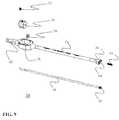
- FIG. 9is a perspective exploded view of the insertion instrument of FIG. 1 , illustrating the component parts of the insertion instrument according to one embodiment of the present invention
- FIG. 10is a perspective view of a spinal fusion system of the present invention, including a cervical fusion implant releasably coupled to a cervical insertion instrument according to one embodiment of the present invention
- FIG. 11is a perspective view of the proximal side of the cervical fusion implant of FIG. 10 , illustrating (among other things) fusion apertures extending between top and bottom surfaces, a plurality of visualization apertures extending through the lateral walls, a plurality of receiving apertures, and a variety of anti-migration features according to one embodiment of the present invention;
- FIG. 12is a perspective view of the distal side cervical fusion implant of FIG. 10 , illustrating (among other things) the visualization apertures and anti-migration features;
- FIG. 13is a top view of the cervical fusion implant of FIG. 10 , illustrating (among other things) the fusion apertures and anti-migration features according to one embodiment of the present invention
- FIG. 14is a side view of the cervical fusion implant of FIG. 10 , illustrating (among other things) the visualization apertures, the anti-migration features, and one of two receiving apertures provided in the proximal end for releasably engaging the cervical insertion instrument of FIG. 10 according to one embodiment of the present invention;
- FIG. 15is a perspective view of the cervical fusion implant of the present invention just prior to attachment to the cervical insertion device according to one embodiment of the present invention
- FIG. 16is a perspective view of the insertion instrument of FIG. 10 in a fully assembled form according to one embodiment of the present invention.
- FIG. 17is a perspective exploded view of the insertion instrument of FIG. 10 , illustrating the component parts of the insertion instrument according to one embodiment of the present invention
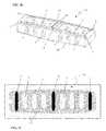
- FIGS. 18 and 19are perspective and side views, respectively, illustrating the “enhanced visualization” feature of the present invention as employed within a lumbar fusion implant according to one embodiment of the present invention
- FIGS. 20 and 21are perspective and side views, respectively, illustrating the “enhanced visualization” feature of the present invention as employed within a lumbar fusion implant according to one embodiment of the present invention.
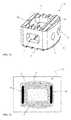
- FIGS. 22 and 23are perspective and side views, respectively, illustrating the “enhanced visualization” feature of the present invention as employed within a cervical fusion implant according to one embodiment of the present invention.
- FIG. 1illustrates, by way of example only, a spinal fusion system 5 for performing spinal fusion between adjacent lumbar vertebrae, including an exemplary spinal fusion implant 10 and an exemplary insertion instrument 20 provided in accordance with the present invention.
- the spinal fusion implant 10may be comprised of any suitable non-bone composition having suitable radiolucent characteristics, including but not limited to polymer compositions (e.g. poly-ether-ether-ketone (PEEK) and/or poly-ether-ketone-ketone (PEKK)) or any combination of PEEK and PEKK.
- PEEKpoly-ether-ether-ketone
- PEKKpoly-ether-ketone-ketone
- the spinal fusion implant 10 of the present inventionmay be dimensioned, by way of example only, having a width ranging between 9 and 18 mm, a height ranging between 8 and 16 mm, and a length ranging between 25 and 45 mm.
- the insertion instrument 20is configured to releasably maintain the exemplary spinal fusion implant 10 in the proper orientation during insertion into a lumbar disc space and thereafter release to deposit the implant 10 .
- the exemplary spinal fusion implant 10having been deposited in the disc space, facilitates spinal fusion over time by maintaining a restored disc height as natural bone growth occurs through and/or past the implant 10 , resulting in the formation of a boney bridge extending between the adjacent vertebral bodies.
- the implant 10is particularly suited for introduction into the disc space via a lateral (trans-psoas) approach to the spine, but may be introduced in any of a variety of approaches, such as posterior, anterior, antero-lateral, and postero-lateral, without departing from the scope of the present invention (depending upon the sizing of the implant 10 ).
- the spinal fusion implant 10 of the present inventionmay be provided with any number of additional features for promoting fusion, such as apertures 2 extending between the upper and lower vertebral bodies which allow a boney bridge to form through the spinal fusion implant 10 .
- this fusionmay be facilitated or augmented by introducing or positioning various osteoinductive materials within the apertures 2 and/or adjacent to the spinal fusion implant 10 .
- Such osteoinductive materialsmay be introduced before, during, or after the insertion of the exemplary spinal fusion implant 10 , and may include (but are not necessarily limited to) autologous bone harvested from the patient receiving the spinal fusion implant 10 , bone allograft, bone xenograft, any number of non-bone implants (e.g. ceramic, metallic, polymer), bone morphogenic protein, and bio-resorbable compositions, including but not limited to any of a variety of poly (D,L-lactide-co-glycolide) based polymers.
- the spinal fusion implant 10 of the present inventionis preferably equipped with one or more visualization apertures 4 situated along the lateral sides, which aid in visualization at the time of implantation and at subsequent clinical evaluations. More specifically, based on the generally radiolucent nature of the implant 10 , the visualization apertures 4 provide the ability to visualize the interior of the implant 10 during X-ray and/or other suitable imaging techniques which are undertaken from the side (or “lateral”) perspective of the implant 10 . If fusion has taken place, the visualization apertures 4 will provide a method for the surgeon to make follow up assessments as to the degree of fusion without any visual interference from the spinal fusion implant 10 . Further, the visualization apertures 4 will provide an avenue for cellular migration to the exterior of the spinal fusion implant 10 . Thus the spinal fusion implant 10 will serve as additional scaffolding for bone fusion on the exterior of the spinal fusion implant 10 .
- FIGS. 2-5depict various embodiments of the exemplary spinal fusion implant 10 .
- each spinal fusion implant 10has a top surface 31 , a bottom surface 33 , lateral sides 14 , a proximal side 22 , and a distal side 16 .
- the top and bottom surfaces 31 , 33are generally parallel. It can be appreciated by one skilled in the art that although the surfaces 31 , 33 are generally parallel to one another, they may be provided in any number of suitable shapes, including but not limited to concave and/or convex. When provided as convex shapes, the top and bottom surfaces 31 , 33 may better match the natural contours of the vertebral end plates. Although not shown, it will be appreciated that the top and bottom surfaces 31 , 33 may be angled relative to one another to better match the natural lordosis of the lumbar and cervical spine or the natural kyphosis of the thoracic spine.
- the exemplary spinal fusion implant 10also preferably includes anti-migration features designed to increase the friction between the spinal fusion implant 10 and the adjacent contacting surfaces of the vertebral bodies so as to prohibit migration of the spinal fusion implant 10 after implantation.
- anti-migration featuresmay include ridges 6 provided along the top surface 31 and/or bottom surface 33 .
- Additional anti-migration featuresmay also include a pair of spike elements 7 disposed within the proximal region of the implant 10 , a pair of spike elements 8 disposed within the distal region of the implant 10 , and a pair of spike elements 9 disposed within the central region of the implant 10 .
- Spike elements 7 , 8 , 9may extend from the top surface 31 and/or bottom surface 33 within the respective proximal, distal and central regions of the implant 10 .
- the spike elements 7 , 8 , 9may be manufactured from any of a variety of suitable materials, including but not limited to a metal, ceramic, and/or polymer material, preferably having radiopaque characteristics.
- the spike elements 7 , 8 , 9may also take any of a variety of suitable shapes, including but not limited to a generally elongated element disposed within the implant 10 such that the ends thereof extend generally perpendicularly from the upper and/or lower surfaces 31 , 33 of the implant 10 . As best appreciated in FIG.
- the spike elements 7 , 8 , 9may each comprise a unitary element extending through upper and lower surfaces 31 , 33 .
- each spike element 7 , 8 , 9may comprise a shorter element which only extends through a single surface 31 , 33 (that is, does not extend through the entire height of the implant 10 ).
- the spike elements 7 , 8 , 9when the spike elements 7 , 8 , 9 are provided having radiodense characteristics and the implant 10 is manufactured from a radiolucent material (such as, by way of example only, PEEK and/or PEKK), the spike elements 7 , 8 , 9 will be readily observable under X-ray or fluoroscopy such that a surgeon may track the progress of the implant 10 during implantation and/or the placement of the implant 10 after implantation.
- the spinal fusion implant 10has two large fusion apertures 2 , separated by a medial support 50 , extending in a vertical fashion through the top surface 31 and bottom surface 33 .
- the fusion apertures 2function primarily as an avenue for bony fusion between adjacent vertebrae.
- the fusion apertures 2may be provided in any of a variety of suitable shapes, including but not limited to the generally rectangular shape best viewed in FIG. 3 , or a generally circular, oblong and/or triangular shape or any combination thereof.
- the spinal fusion implant 10may have a plurality of visualization apertures 4 which allow a clinician to make visual observations of the degree of bony fusion un-obscured by the lateral side 14 to facilitate further diagnosis and treatment.
- the visualization apertures 4may be provided in any of a variety of suitable shapes, including but not limited to the generally oblong shape best viewed in FIG. 4 , or a generally circular, rectangular and/or triangular shape or any combination thereof.
- the spinal fusion implant 10may be provided with any number of suitable features for engaging the insertion instrument 20 without departing from the scope of the present invention.
- one engagement mechanisminvolves providing a threaded receiving aperture 12 in the proximal sidewall 22 of the spinal fusion implant 10 of the present invention.
- the threaded receiving aperture 12is dimensioned to threadably receive a threaded connector 24 on the insertion instrument 20 (as will be described in greater detail below).
- the receiving aperture 12extends inwardly from the proximal side 22 in a generally perpendicular fashion relative to the proximal side 22 .
- the receiving aperture 12may be provided having any number of suitable shapes or cross-sections, including but not limited to rectangular or triangular.
- the spinal fusion implant 10is preferably equipped with a pair of grooved purchase regions 60 , 61 extending generally horizontally from either side of the receiving aperture 12 .
- the grooved purchase regions 60 , 61are dimensioned to receive corresponding distal head ridges 62 , 63 on the insertion instrument 20 (as will be described in greater detail below), which collectively provide an enhanced engagement between the implant 10 and instrument 20 .
- FIGS. 6-9detail the exemplary insertion instrument 20 according to one embodiment of the invention.
- the exemplary insertion instrument 20includes an elongate tubular element 28 and an inserter shaft 44 .
- the elongate tubular element 28is constructed with a distal head 26 at its distal end, distal head ridges 62 , 63 on the distal end of the distal head 26 , a thumbwheel housing 38 at its proximal end and a handle 42 at its proximal end.
- the elongate tubular element 28is generally cylindrical and of a length sufficient to allow the device to span from the surgical target site to a location sufficiently outside the patient's body so the handle 42 and thumbwheel housing 38 can be easily accessed by a clinician or a complimentary controlling device.
- the elongate tubular element 28is dimensioned to receive a spring 46 and the proximal end of the inserter shaft 44 into the inner bore 64 of the elongate tubular element 28 .
- the inserter shaft 44is dimensioned such that the threaded connector 24 at the distal end of the inserter shaft 44 just protrudes past the distal head ridges 62 , 63 to allow engagement with the receiving aperture 12 of the spinal fusion implant 10 . It should be appreciated by one skilled in the art that such a construction allows the inserter shaft 44 to be able to rotate freely within the elongate tubular element 28 while stabilized by a spring 46 to reduce any slidable play in the insertion instrument 20 .
- the handle 42is generally disposed at the proximal end of the insertion instrument 20 .
- the handle 42is fixed to the thumbwheel housing 38 allowing easy handling by the clinician. Because the handle 42 is fixed the clinician has easy access to the thumbwheel 34 and can stably turn the thumbwheel 34 relative to the thumbwheel housing 38 . Additionally, the relative orientation of the thumbwheel housing 38 to the handle 42 orients the clinician with respect to the distal head 26 and distal head ridge 62 .
- the thumbwheel housing 38holds a thumbwheel 34 , a set screw 32 , and a spacer 36 .
- the inserter shaft 44is attached to the thumbwheel 34 and is freely rotatable with low friction due to the spacer 36 .
- One skilled in the artcan appreciate myriad methods of assembling a housing similar to the above described.
- FIG. 6details the distal head ridge of the exemplary insertion instrument 20 coupled to the spinal fusion implant 10 through the purchase regions 60 , 61 .
- the distal head ridges 62 , 63are dimensioned to fit slidably into the purchase regions 60 , 61 with low friction to allow accurate engagement of the threaded connector 24 to the receiving aperture 12 of the spinal fusion implant 10 .
- the outer dimension of the threaded connector 24is smaller than the largest outer dimension of the distal head 26 and elongate tubular element 28 .
- other methods of creating a gripping surfaceare contemplated including but not limited to knurling or facets.
- the clinicianIn order to use the system to perform a spinal fusion procedure, the clinician must first designate the appropriate implant size. After the spinal fusion implant 10 is chosen, the distal head ridges 62 , 63 of the inserter shaft 44 are inserted into the purchase regions 60 , 61 of the spinal fusion implant 10 . At that time the spinal fusion implant 10 and insertion instrument 20 are slidably engaged with one another. Before the clinician can manipulate the combined spinal fusion implant 10 and insertion instrument 20 , they must be releasably secured together. In order to secure the spinal fusion implant 10 onto the threaded connector 24 of the inserter instrument 20 , the clinician employs the thumbwheel 34 to rotate the inserter shaft 44 and threaded connector 24 . The rotation of the threaded connector 24 will releasably engage the receiving aperture of the spinal fusion implant 10 and stabilize the insertion instrument 20 relative to the spinal fusion implant 10 .
- a cliniciancan utilize the secured system in either an open or minimally invasive spinal fusion procedure.
- a working channelis created in a patient that reaches the targeted spinal level.
- the intervertebral spacemay be prepared via any number of well known preparation tools, including but not limited to kerrisons, rongeurs, pituitaries, and rasps.
- the insertion instrument 20is used to place a spinal fusion implant 10 into the prepared intervertebral space. Once the implant 10 is inserted into the prepared space, the implant 10 is released from the insertion instrument 20 by rotating the thumbwheel 34 to disengage the threaded connector 24 from the receiving aperture 12 .
- That motionremoves the compressive force on the purchase regions 60 , 61 between the distal head 26 and the distal head ridges 62 , 63 of the spinal fusion implant 10 and allows the insertion instrument to be slidably removed from the implant 10 .
- the insertion instrument 20is removed from the working channel and the channel is closed.
- additional materialsmay be included in the procedure before, during or after the insertion of the spinal fusion implant 10 to aid the natural fusion of the targeted spinal level.
- FIG. 10illustrates a spinal fusion system 105 for performing spinal fusion between adjacent cervical vertebrae, including an exemplary spinal fusion implant 110 and an exemplary cervical insertion instrument 120 provided in accordance with the present invention.
- the spinal fusion implant 110may comprise of any suitable non-bone composition having suitable radiolucent characteristics, including but not limited to polymer compositions (e.g. poly-ether-ether-ketone (PEEK) and/or poly-ether-ketone-ketone (PEKK)) or any combination of PEEK and PEKK.
- PEEKpoly-ether-ether-ketone
- PEKKpoly-ether-ketone-ketone
- the spinal fusion implant 110may be provided in any number of suitable sizes, such as, by way of example only, a width ranging between 11 to 14 mm, a height ranging between 5 and 12 mm, and a length ranging from 14 and 16 mm.
- the cervical insertion instrument 120is configured to releasably maintain the exemplary cervical fusion implant 110 in the proper orientation for insertion.
- the cervical fusion implant 110may be simultaneously introduced into a disc space while locked within the cervical insertion instrument 120 and thereafter released.
- the exemplary cervical fusion implant 110having been deposited in the disc space, effects spinal fusion over time as the natural bone healing process integrates and binds the implant with the adjacent vertebral bodies. This fusion may be facilitated or augmented by introducing or positioning various materials in a space created within or adjacent to the cervical fusion implant 110 . Those materials may be introduced before, during, or after the insertion of the exemplary cervical fusion implant 110 .
- the additional materialmay include bone autograft harvested from the patient receiving the spinal fusion implant 10 , one or more additional bone allograft, bio-resorbables or xenograft implants, any number of non-bone implants, and any number of fusion promoting compounds such as bone morphogenic protein.
- FIGS. 11-14depict various embodiments of the exemplary cervical fusion implant 110 .
- each cervical fusion implant 110has a top surface 31 , a bottom surface 33 , lateral sides 14 , a proximal side 22 , and a distal side 16 .
- the top and bottom surfaces 31 , 33are generally parallel. It can be appreciated by one skilled in the art that although the surfaces are generally parallel, that the top 31 and bottom 33 surfaces may be angled with respect to one another to match the natural curve of the spine (i.e. lordosis or kyphosis).
- implants for the cervical or lumbar regions of the spinewill have anterior height greater than the posterior height to match the natural lordosis in those regions.
- the implants designed for implantation into the thoracic regionwill be manufactured with a posterior height greater than the anterior height to match the natural kyophosis in that region.
- the angled surfacecan aid in overall fit within the vertebral disc space.
- the cervical fusion implant 110preferably includes two receiving apertures 12 which are centrally aligned on the proximal side 22 .
- the receiving apertures 12extend inwardly from the proximal side 22 in a generally perpendicular fashion relative to the proximal side 22 .
- the receiving aperture 12may be provided having any number of suitable shapes or cross-sections, including but not limited to rectangular or triangular.
- the exemplary cervical fusion implant 110also preferably includes anti-migration features such as anti-migration teeth 6 along the top surface 31 and bottom surface 33 .
- Additional anti-migration featuresmay include a plurality of proximal anti-migration spikes 68 and/or distal anti-migration spikes 70 integrated vertically through the cervical fusion implant 110 .
- the anti-migration featuresincrease the friction between the cervical fusion implant 110 and the adjacent contacting surfaces of the vertebral bodies. That friction prohibits migration of the cervical fusion implant 110 during the propagation of natural bony fusion. It should be appreciated by one skilled in the art that such anti-migration teeth 6 can be oriented in a any manner other than generally vertically (as shown) without departing from the scope of the present invention.
- the spikes 68 , 70may be constructed from any of a variety of radiopaque materials, including but not limited to a metal, ceramic, and/or polymer material.
- the spike elements 68 , 70are provided having such radiodense characteristics, and the implant 110 is manufactured from a radiolucent material (such as, by way of example only, PEEK and/or PEKK), the spike elements 68 , 70 will be readily observable under X-ray or fluoroscopy such that a surgeon may track the progress of the implant 110 during implantation and/or the placement of the implant 110 after implantation.
- the cervical fusion implant 110has one large fusion aperture 2 , extending in a vertical fashion through the top surface 31 and bottom surface 33 which will function primarily as the avenue for bony fusion between adjacent vertebrae.
- the cervical fusion implant 110may have a plurality of visualization apertures 4 which can also serve as an avenue of bony fusion on the lateral sides 14 via cell migration or additional adjuvants.
- the visualization apertures 4serve an additional function of allowing a clinician to make visual observations of the degree of bony fusion un-obscured by the lateral side 14 to facilitate further diagnosis and treatment.
- FIG. 15illustrates, by way of example, the orientation of the cervical fusion implant 110 prior to attachment to the cervical insertion instrument 120 by a clinician.
- the current embodimentshows a slidable engagement
- various other methods of engagementare contemplated, such as, threadable or hooking features.
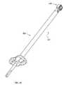
- FIGS. 16-17detail the tubular lock member 21 of the exemplary cervical inserter instrument 110 .
- the tubular lock member 21includes a central bore 25 dimensioned to receive the proximal end of the elongate fork member 11 therein.
- the internal dimension of the central bore 25is smaller than the largest freestanding outer dimension of the taper feature 19 .
- the portion of the elongate fork member 11 that may be received by the central bore 25 of the tubular lock member 21is limited by interference between the distal end of the tubular lock member 21 and the taper feature 19 of the elongate fork member 11 .
- the outer dimension of the threaded feature 13 of the elongate fork member 11is smaller than the largest outer dimension of the taper feature 19 on the elongate fork member 11 .
- a thread feature 23(not shown) at the proximal end of the tubular lock member 21 is situated inside the central bore 25 .
- the thread feature 23matches the thread feature 13 on the elongate fork member 11 so that they can be threadably attached to one another.
- two semi-circular wings 27may be provided protruding laterally outward from either side of the tubular lock member 21 .
- other methods of creating a gripping surfaceare contemplated including but not limited to knurling or facets.
- a cliniciancan utilize the secured system in either an open or minimally invasive spinal fusion procedure.
- a working channelis created in a patient that reaches the targeted spinal level.
- the intervertebral spacewould be prepared (via known instruments as described above).
- the insertion instrument 120is used to place a cervical fusion implant 110 into the prepared intervertebral space.
- the implant 110is released from the cervical insertion instrument 120 by retracting the tubular lock member 21 from the elongate fork member 11 by rotating the tubular lock member 21 with respect to the elongate fork member 11 in the opposite direction from that used to initially secure the implant 110 .
- That motionremoves the compressive force on the purchase region 39 between the apertures 12 of the cervical fusion implant 110 and allows the engagement features 17 to be slidably removed from the apertures 12 .
- the cervical inserter instrument 120is removed from the working channel and the channel is closed.
- additional materialsmay be included in the procedure before, during or after the insertion of the cervical fusion implant 110 to aid the natural fusion of the targeted spinal level.
- the clinicianIn order to use the system to perform a spinal fusion procedure, the clinician must first designate the appropriate implant size. After the cervical fusion implant 110 is chosen, the engagement features 17 of the elongate fork member 11 are inserted into the apertures 12 on the implant 110 . At that time the cervical fusion implant 110 and elongate fork member 11 are slidably engaged with one another. Before the clinician can manipulate the combined cervical fusion implant 110 and elongated fork member 11 , they must be releasably secured together. In order to secure the cervical fusion implant 110 onto the elongate fork member 11 , the clinician would next employ the tubular lock member 21 .
- the clinicianwould insert the proximal end of the elongate fork member 11 into the central bore 25 of the tubular lock member 21 at its distal end.
- the tubular lock member 21would then be advanced over the elongate fork member 11 until the thread feature 13 of that member and the thread feature 23 of the tubular lock member 21 become engaged.
- tubular lock member 21Once engaged, advancement of the tubular lock member requires rotation of the tubular lock member 21 with respect to the elongate fork member 11 .
- the distal end of the tubular lock member 21would contact the taper feature 19 of the elongate fork member 11 .
- the tubular lock member 21would be advanced creating greater interference as the distal end approaches the distal end of the taper feature 19 which has the larger outer dimension. The increasing interference would laterally displace the clamping arms 15 of the elongate fork member 11 towards each other.
- FIG. 18illustrates an implant 10 dimensioned particularly for use in a posterior approach (PLIF) having (by way of example only) a width ranging between 9 and 11 mm, a height ranging between 8 and 14 mm, and a length ranging between 25 and 30 mm.
- FIG. 19illustrates the implant 10 of FIG. 18 from a side perspective via as taken via X-ray or fluoroscopy techniques, clearly showing the location of the spike elements 7 and 8 (there is no central spike element 9 as with FIG. 1 ) relative to the implant 10 and visualization apertures 4 .
- FIG. 18illustrates an implant 10 dimensioned particularly for use in a posterior approach (PLIF) having (by way of example only) a width ranging between 9 and 11 mm, a height ranging between 8 and 14 mm, and a length ranging between 25 and 30 mm.
- FIG. 19illustrates the implant 10 of FIG. 18 from a side perspective via as taken via X-ray or fluoroscopy techniques, clearly showing the location of the spike elements 7 and
- FIG. 20illustrates an implant 10 dimensioned particularly for use in a lateral approach (XLIFTM by NuVasive) having (by way of example only) a width of approximately 18 mm, a height ranging between 8 and 16 mm, and a length ranging between 40 and 45 mm.
- FIG. 21illustrates the implant 10 of FIG. 20 from a side perspective via as taken via X-ray or fluoroscopy techniques, clearly showing the location of the spike elements 7 , 8 , 9 relative to the implant 10 and visualization apertures 4 .
- FIG. 22illustrates an implant 110 dimensioned particularly for use in the cervical spine having (by way of example only) a width of approximately 11 mm, a height ranging between 5 and 12 mm, and a length of approximately 14 mm.
- FIG. 23illustrates the implant 110 of FIG. 22 from a side perspective via as taken via X-ray or fluoroscopy techniques, clearly showing the location of the spike elements 66 relative to the implant 110 and visualization apertures 4 .
- a surgeonmay easily track the progress of the implant 10 , 110 during implantation and/or after implantation by visualizing the spike elements 7 , 8 , 9 and 66 , respectively, under X-ray and/or fluoroscopy according to the present invention.
- spinal fusion implants of the present inventionmay be suitable for accomplishing fusion in the thoracic spine without departing from the scope of the present invention.
- insertion tools described hereinmay be employed with implants of any number of suitable constructions, including but not limited to metal, ceramic, plastic or composite.
Landscapes
- Health & Medical Sciences (AREA)
- Engineering & Computer Science (AREA)
- Biomedical Technology (AREA)
- Orthopedic Medicine & Surgery (AREA)
- Neurology (AREA)
- Transplantation (AREA)
- Heart & Thoracic Surgery (AREA)
- Oral & Maxillofacial Surgery (AREA)
- Cardiology (AREA)
- Vascular Medicine (AREA)
- Life Sciences & Earth Sciences (AREA)
- Animal Behavior & Ethology (AREA)
- General Health & Medical Sciences (AREA)
- Public Health (AREA)
- Veterinary Medicine (AREA)
- Physical Education & Sports Medicine (AREA)
- Prostheses (AREA)
Abstract
Description
Claims (27)
Priority Applications (11)
| Application Number | Priority Date | Filing Date | Title |
|---|---|---|---|
| US13/441,092US8361156B2 (en) | 2004-03-29 | 2012-04-06 | Systems and methods for spinal fusion |
| US13/747,765US8608804B2 (en) | 2004-03-29 | 2013-01-23 | Systems and methods for spinal fusion |
| US13/748,925US8574301B2 (en) | 2004-03-29 | 2013-01-24 | Systems and methods for spinal fusion |
| US14/066,285US8685105B2 (en) | 2004-03-29 | 2013-10-29 | Systems and methods for spinal fusion |
| US14/171,484US8814940B2 (en) | 2004-03-29 | 2014-02-03 | Systems and methods for spinal fusion |
| US14/314,823US9180021B2 (en) | 2004-03-29 | 2014-06-25 | Systems and methods for spinal fusion |
| US14/921,760US9474627B2 (en) | 2004-03-29 | 2015-10-23 | Systems and methods for spinal fusion |
| US15/272,071US9744053B2 (en) | 2004-03-29 | 2016-09-21 | Systems and methods for spinal fusion |
| US15/690,053US20180014946A1 (en) | 2004-03-29 | 2017-08-29 | Systems and Methods for Spinal Fusion |
| US16/656,244US20200046516A1 (en) | 2004-03-29 | 2019-10-17 | Systems and methods for spinal fusion |
| US17/204,103US20210267765A1 (en) | 2004-03-29 | 2021-03-17 | Systems and methods for spinal fusion |
Applications Claiming Priority (5)
| Application Number | Priority Date | Filing Date | Title |
|---|---|---|---|
| US55753604P | 2004-03-29 | 2004-03-29 | |
| US11/093,409US7918891B1 (en) | 2004-03-29 | 2005-03-29 | Systems and methods for spinal fusion |
| US13/079,645US8187334B2 (en) | 2004-03-29 | 2011-04-04 | System and methods for spinal fusion |
| US13/440,062US8246686B1 (en) | 2004-03-29 | 2012-04-05 | Systems and methods for spinal fusion |
| US13/441,092US8361156B2 (en) | 2004-03-29 | 2012-04-06 | Systems and methods for spinal fusion |
Related Parent Applications (1)
| Application Number | Title | Priority Date | Filing Date |
|---|---|---|---|
| US13/440,062ContinuationUS8246686B1 (en) | 2004-03-29 | 2012-04-05 | Systems and methods for spinal fusion |
Related Child Applications (1)
| Application Number | Title | Priority Date | Filing Date |
|---|---|---|---|
| US13/747,765ContinuationUS8608804B2 (en) | 2004-03-29 | 2013-01-23 | Systems and methods for spinal fusion |
Publications (2)
| Publication Number | Publication Date |
|---|---|
| US20120209388A1 US20120209388A1 (en) | 2012-08-16 |
| US8361156B2true US8361156B2 (en) | 2013-01-29 |
Family
ID=43805831
Family Applications (14)
| Application Number | Title | Priority Date | Filing Date |
|---|---|---|---|
| US11/093,409Active2026-01-31US7918891B1 (en) | 2004-03-29 | 2005-03-29 | Systems and methods for spinal fusion |
| US13/079,645Expired - LifetimeUS8187334B2 (en) | 2004-03-29 | 2011-04-04 | System and methods for spinal fusion |
| US13/440,062Expired - LifetimeUS8246686B1 (en) | 2004-03-29 | 2012-04-05 | Systems and methods for spinal fusion |
| US13/441,092Expired - LifetimeUS8361156B2 (en) | 2004-03-29 | 2012-04-06 | Systems and methods for spinal fusion |
| US13/747,765Expired - LifetimeUS8608804B2 (en) | 2004-03-29 | 2013-01-23 | Systems and methods for spinal fusion |
| US13/748,925Expired - LifetimeUS8574301B2 (en) | 2004-03-29 | 2013-01-24 | Systems and methods for spinal fusion |
| US14/066,285Expired - LifetimeUS8685105B2 (en) | 2004-03-29 | 2013-10-29 | Systems and methods for spinal fusion |
| US14/171,484Expired - LifetimeUS8814940B2 (en) | 2004-03-29 | 2014-02-03 | Systems and methods for spinal fusion |
| US14/314,823Expired - LifetimeUS9180021B2 (en) | 2004-03-29 | 2014-06-25 | Systems and methods for spinal fusion |
| US14/921,760Expired - LifetimeUS9474627B2 (en) | 2004-03-29 | 2015-10-23 | Systems and methods for spinal fusion |
| US15/272,071Expired - Fee RelatedUS9744053B2 (en) | 2004-03-29 | 2016-09-21 | Systems and methods for spinal fusion |
| US15/690,053AbandonedUS20180014946A1 (en) | 2004-03-29 | 2017-08-29 | Systems and Methods for Spinal Fusion |
| US16/656,244AbandonedUS20200046516A1 (en) | 2004-03-29 | 2019-10-17 | Systems and methods for spinal fusion |
| US17/204,103AbandonedUS20210267765A1 (en) | 2004-03-29 | 2021-03-17 | Systems and methods for spinal fusion |
Family Applications Before (3)
| Application Number | Title | Priority Date | Filing Date |
|---|---|---|---|
| US11/093,409Active2026-01-31US7918891B1 (en) | 2004-03-29 | 2005-03-29 | Systems and methods for spinal fusion |
| US13/079,645Expired - LifetimeUS8187334B2 (en) | 2004-03-29 | 2011-04-04 | System and methods for spinal fusion |
| US13/440,062Expired - LifetimeUS8246686B1 (en) | 2004-03-29 | 2012-04-05 | Systems and methods for spinal fusion |
Family Applications After (10)
| Application Number | Title | Priority Date | Filing Date |
|---|---|---|---|
| US13/747,765Expired - LifetimeUS8608804B2 (en) | 2004-03-29 | 2013-01-23 | Systems and methods for spinal fusion |
| US13/748,925Expired - LifetimeUS8574301B2 (en) | 2004-03-29 | 2013-01-24 | Systems and methods for spinal fusion |
| US14/066,285Expired - LifetimeUS8685105B2 (en) | 2004-03-29 | 2013-10-29 | Systems and methods for spinal fusion |
| US14/171,484Expired - LifetimeUS8814940B2 (en) | 2004-03-29 | 2014-02-03 | Systems and methods for spinal fusion |
| US14/314,823Expired - LifetimeUS9180021B2 (en) | 2004-03-29 | 2014-06-25 | Systems and methods for spinal fusion |
| US14/921,760Expired - LifetimeUS9474627B2 (en) | 2004-03-29 | 2015-10-23 | Systems and methods for spinal fusion |
| US15/272,071Expired - Fee RelatedUS9744053B2 (en) | 2004-03-29 | 2016-09-21 | Systems and methods for spinal fusion |
| US15/690,053AbandonedUS20180014946A1 (en) | 2004-03-29 | 2017-08-29 | Systems and Methods for Spinal Fusion |
| US16/656,244AbandonedUS20200046516A1 (en) | 2004-03-29 | 2019-10-17 | Systems and methods for spinal fusion |
| US17/204,103AbandonedUS20210267765A1 (en) | 2004-03-29 | 2021-03-17 | Systems and methods for spinal fusion |
Country Status (1)
| Country | Link |
|---|---|
| US (14) | US7918891B1 (en) |
Cited By (31)
| Publication number | Priority date | Publication date | Assignee | Title |
|---|---|---|---|---|
| US20110125266A1 (en)* | 2007-12-28 | 2011-05-26 | Nuvasive, Inc. | Spinal Surgical Implant and Related Methods |
| US8574301B2 (en)* | 2004-03-29 | 2013-11-05 | Nuvasive, Inc. | Systems and methods for spinal fusion |
| US8758344B2 (en) | 1988-06-13 | 2014-06-24 | Warsaw Orthopedic, Inc. | Spinal implant and instruments |
| USD735336S1 (en) | 2008-10-15 | 2015-07-28 | Nuvasive, Inc. | Intervertebral implant |
| US9132021B2 (en) | 2011-10-07 | 2015-09-15 | Pioneer Surgical Technology, Inc. | Intervertebral implant |
| US9168152B2 (en) | 2008-02-29 | 2015-10-27 | Nuvasive, Inc. | Implants and methods for spinal fusion |
| US9186261B2 (en) | 2007-03-07 | 2015-11-17 | Nuvasive, Inc. | System and methods for spinal fusion |
| US9198765B1 (en) | 2011-10-31 | 2015-12-01 | Nuvasive, Inc. | Expandable spinal fusion implants and related methods |
| USD745159S1 (en) | 2013-10-10 | 2015-12-08 | Nuvasive, Inc. | Intervertebral implant |
| USD747485S1 (en) | 2011-11-03 | 2016-01-12 | Nuvasive, Inc. | Intervertebral implant |
| USD754346S1 (en) | 2009-03-02 | 2016-04-19 | Nuvasive, Inc. | Spinal fusion implant |
| USD788308S1 (en) | 2007-09-18 | 2017-05-30 | Nuvasive, Inc. | Intervertebral implant |
| US9750490B2 (en) | 2002-06-26 | 2017-09-05 | Nuvasive, Inc. | Surgical access system and related methods |
| US9788822B2 (en) | 2003-09-25 | 2017-10-17 | Nuvasive, Inc. | Surgical access system and related methods |
| US9795371B2 (en) | 2003-01-16 | 2017-10-24 | Nuvasive, Inc. | Surgical access system and related methods |
| US9820729B2 (en) | 2002-10-08 | 2017-11-21 | Nuvasive, Inc. | Surgical access system and related methods |
| US9918851B2 (en) | 2014-10-22 | 2018-03-20 | Stryker European Holdings I, Llc | Spinal fusion implant |
| US9931077B2 (en) | 2001-07-11 | 2018-04-03 | Nuvasive, Inc. | System and methods for determining nerve proximity, direction and pathology during surgery |
| US9949840B1 (en) | 2011-04-01 | 2018-04-24 | William D. Smith | Systems and methods for performing spine surgery |
| USD858769S1 (en) | 2014-11-20 | 2019-09-03 | Nuvasive, Inc. | Intervertebral implant |
| US10507120B2 (en) | 2001-09-25 | 2019-12-17 | Nuvasive, Inc. | Systems and methods for performing surgical procedures and assessments |
| US10653308B2 (en) | 2003-10-17 | 2020-05-19 | Nuvasive, Inc. | Surgical access system and related methods |
| US10687797B2 (en) | 2008-12-18 | 2020-06-23 | Howmedica Osteonics Corp. | Lateral access system for the lumbar spine |
| US10736752B1 (en) | 2017-10-24 | 2020-08-11 | Omnia Medical, LLC | Multi-material multi-component spinal implant |
| USD907771S1 (en) | 2017-10-09 | 2021-01-12 | Pioneer Surgical Technology, Inc. | Intervertebral implant |
| US11096802B2 (en) | 2018-03-03 | 2021-08-24 | K2M, Inc. | Intervertebral trial with marker |
| US11147682B2 (en) | 2017-09-08 | 2021-10-19 | Pioneer Surgical Technology, Inc. | Intervertebral implants, instruments, and methods |
| US11166709B2 (en) | 2016-08-23 | 2021-11-09 | Stryker European Operations Holdings Llc | Instrumentation and methods for the implantation of spinal implants |
| US11191532B2 (en) | 2018-03-30 | 2021-12-07 | Stryker European Operations Holdings Llc | Lateral access retractor and core insertion |
| US11564674B2 (en) | 2019-11-27 | 2023-01-31 | K2M, Inc. | Lateral access system and method of use |
| US11766339B1 (en) | 2017-10-24 | 2023-09-26 | Omnia Medical, LLC | Multi-material multi-component spinal implant |
Families Citing this family (151)
| Publication number | Priority date | Publication date | Assignee | Title |
|---|---|---|---|---|
| US6974480B2 (en) | 2001-05-03 | 2005-12-13 | Synthes (Usa) | Intervertebral implant for transforaminal posterior lumbar interbody fusion procedure |
| WO2006042241A2 (en)* | 2004-10-08 | 2006-04-20 | Nuvasive, Inc. | Surgical access system and related methods |
| US20110282392A1 (en)* | 2006-10-30 | 2011-11-17 | Tissue Regeneration Systems, Inc. | Degradable cage for bone fusion |
| US20080161929A1 (en) | 2006-12-29 | 2008-07-03 | Mccormack Bruce | Cervical distraction device |
| WO2009089367A2 (en) | 2008-01-09 | 2009-07-16 | Providence Medical Technology, Inc. | Methods and apparatus for accessing and treating the facet joint |
| US7789099B2 (en) | 2008-01-24 | 2010-09-07 | Go PaPa, LLLC. | Collapsible truss assembly |
| US8088163B1 (en) | 2008-02-06 | 2012-01-03 | Kleiner Jeffrey B | Tools and methods for spinal fusion |
| US8840622B1 (en) | 2008-02-14 | 2014-09-23 | Nuvasive, Inc. | Implant installation assembly and related methods |
| US8343163B1 (en) | 2008-02-14 | 2013-01-01 | Nuvasive, Inc. | Spinal implant installation device |
| US20210378834A1 (en) | 2008-05-22 | 2021-12-09 | Spinal Surgical Strategies, Inc., A Nevada Corporation D/B/A Kleiner Device Labs | Spinal fusion cage system with inserter |
| US11224521B2 (en) | 2008-06-06 | 2022-01-18 | Providence Medical Technology, Inc. | Cervical distraction/implant delivery device |
| US8267966B2 (en) | 2008-06-06 | 2012-09-18 | Providence Medical Technology, Inc. | Facet joint implants and delivery tools |
| EP2361046B1 (en) | 2008-06-06 | 2019-04-24 | Providence Medical Technology, Inc. | Cervical distraction/implant delivery device |
| US9381049B2 (en) | 2008-06-06 | 2016-07-05 | Providence Medical Technology, Inc. | Composite spinal facet implant with textured surfaces |
| US9333086B2 (en) | 2008-06-06 | 2016-05-10 | Providence Medical Technology, Inc. | Spinal facet cage implant |
| CA2725811A1 (en) | 2008-06-06 | 2009-12-10 | Providence Medical Technology, Inc. | Facet joint implants and delivery tools |
| US8361152B2 (en) | 2008-06-06 | 2013-01-29 | Providence Medical Technology, Inc. | Facet joint implants and delivery tools |
| US9700431B2 (en)* | 2008-08-13 | 2017-07-11 | Smed-Ta/Td, Llc | Orthopaedic implant with porous structural member |
| US8366748B2 (en) | 2008-12-05 | 2013-02-05 | Kleiner Jeffrey | Apparatus and method of spinal implant and fusion |
| USD656610S1 (en) | 2009-02-06 | 2012-03-27 | Kleiner Jeffrey B | Spinal distraction instrument |
| US9247943B1 (en) | 2009-02-06 | 2016-02-02 | Kleiner Intellectual Property, Llc | Devices and methods for preparing an intervertebral workspace |
| US9687357B2 (en) | 2009-03-12 | 2017-06-27 | Nuvasive, Inc. | Vertebral body replacement |
| US9387090B2 (en) | 2009-03-12 | 2016-07-12 | Nuvasive, Inc. | Vertebral body replacement |
| US9351845B1 (en) | 2009-04-16 | 2016-05-31 | Nuvasive, Inc. | Method and apparatus for performing spine surgery |
| US10842642B2 (en) | 2009-04-16 | 2020-11-24 | Nuvasive, Inc. | Methods and apparatus of performing spine surgery |
| FR2944692B1 (en)* | 2009-04-27 | 2011-04-15 | Medicrea International | MATERIAL OF VERTEBRAL OSTEOSYNTHESIS |
| USD750249S1 (en) | 2014-10-20 | 2016-02-23 | Spinal Surgical Strategies, Llc | Expandable fusion cage |
| US8685031B2 (en) | 2009-09-18 | 2014-04-01 | Spinal Surgical Strategies, Llc | Bone graft delivery system |
| USD723682S1 (en) | 2013-05-03 | 2015-03-03 | Spinal Surgical Strategies, Llc | Bone graft delivery tool |
| US10973656B2 (en) | 2009-09-18 | 2021-04-13 | Spinal Surgical Strategies, Inc. | Bone graft delivery system and method for using same |
| US9629729B2 (en) | 2009-09-18 | 2017-04-25 | Spinal Surgical Strategies, Llc | Biological delivery system with adaptable fusion cage interface |
| US8906028B2 (en) | 2009-09-18 | 2014-12-09 | Spinal Surgical Strategies, Llc | Bone graft delivery device and method of using the same |
| US10245159B1 (en) | 2009-09-18 | 2019-04-02 | Spinal Surgical Strategies, Llc | Bone graft delivery system and method for using same |
| US9186193B2 (en) | 2009-09-18 | 2015-11-17 | Spinal Surgical Strategies, Llc | Fusion cage with combined biological delivery system |
| US20170238984A1 (en) | 2009-09-18 | 2017-08-24 | Spinal Surgical Strategies, Llc | Bone graft delivery device with positioning handle |
| US9060877B2 (en) | 2009-09-18 | 2015-06-23 | Spinal Surgical Strategies, Llc | Fusion cage with combined biological delivery system |
| US9173694B2 (en) | 2009-09-18 | 2015-11-03 | Spinal Surgical Strategies, Llc | Fusion cage with combined biological delivery system |
| US8740983B1 (en)* | 2009-11-11 | 2014-06-03 | Nuvasive, Inc. | Spinal fusion implants and related methods |
| WO2011059498A1 (en) | 2009-11-11 | 2011-05-19 | Nuvasive, Inc. | Surgical access system and related methods |
| US9480511B2 (en) | 2009-12-17 | 2016-11-01 | Engage Medical Holdings, Llc | Blade fixation for ankle fusion and arthroplasty |
| US9381045B2 (en) | 2010-01-13 | 2016-07-05 | Jcbd, Llc | Sacroiliac joint implant and sacroiliac joint instrument for fusing a sacroiliac joint |
| US9421109B2 (en) | 2010-01-13 | 2016-08-23 | Jcbd, Llc | Systems and methods of fusing a sacroiliac joint |
| US9333090B2 (en) | 2010-01-13 | 2016-05-10 | Jcbd, Llc | Systems for and methods of fusing a sacroiliac joint |
| CA3002234C (en) | 2010-01-13 | 2020-07-28 | Jcbd, Llc | Sacroiliac joint fixation fusion system |
| WO2014015309A1 (en) | 2012-07-20 | 2014-01-23 | Jcbd, Llc | Orthopedic anchoring system and methods |
| US8945227B2 (en)* | 2010-02-01 | 2015-02-03 | X-Spine Systems, Inc. | Spinal implant co-insertion system and method |
| EP2547292B1 (en) | 2010-03-16 | 2019-04-24 | Pinnacle Spine Group, LLC | Ntervertebral implants and graft delivery systems |
| DE102010018379B4 (en)* | 2010-04-26 | 2018-10-18 | Peter Metz-Stavenhagen | Spine implant and tool for this |
| WO2012040206A1 (en) | 2010-09-20 | 2012-03-29 | Synthes Usa, Llc | Spinal access retractor |
| EP2651341B1 (en) | 2010-12-16 | 2017-01-04 | Engage Medical Holdings, LLC | Arthroplasty systems and methods |
| US8518087B2 (en) | 2011-03-10 | 2013-08-27 | Interventional Spine, Inc. | Method and apparatus for minimally invasive insertion of intervertebral implants |
| US8394129B2 (en) | 2011-03-10 | 2013-03-12 | Interventional Spine, Inc. | Method and apparatus for minimally invasive insertion of intervertebral implants |
| DE102011018692B4 (en) | 2011-04-26 | 2016-06-23 | Peter Metz-Stavenhagen | Spinal implant, tool and method of distraction of the spinal implant |
| EP2720628B1 (en) | 2011-06-17 | 2021-08-11 | Jcbd, Llc | Sacroiliac joint implant system |
| US9770340B2 (en)* | 2011-09-16 | 2017-09-26 | Globus Medical, Inc. | Multi-piece intervertebral implants |
| US9539109B2 (en) | 2011-09-16 | 2017-01-10 | Globus Medical, Inc. | Low profile plate |
| US9398960B2 (en) | 2011-09-16 | 2016-07-26 | Globus Medical, Inc. | Multi-piece intervertebral implants |
| US10555821B2 (en) | 2011-09-21 | 2020-02-11 | Tov Inge Vestgaarden | Method and apparatus for spinal interbody fusion including fixation or locking plate |
| US20160106549A1 (en) | 2011-09-21 | 2016-04-21 | Vg Innovations, Llc | Interconnected Locking Plates for Adjacent Spinal Vertebral Bodies |
| US9220607B2 (en) | 2011-10-28 | 2015-12-29 | Warsaw Oorthopedic, Inc. | Pivotable interbody implant system |
| US9254130B2 (en) | 2011-11-01 | 2016-02-09 | Hyun Bae | Blade anchor systems for bone fusion |
| US9655746B2 (en) | 2011-11-09 | 2017-05-23 | Globus Medical, Inc. | Intervertebral spinal implant |
| US8795167B2 (en)* | 2011-11-15 | 2014-08-05 | Baxano Surgical, Inc. | Spinal therapy lateral approach access instruments |
| US10238382B2 (en) | 2012-03-26 | 2019-03-26 | Engage Medical Holdings, Llc | Blade anchor for foot and ankle |
| US8882818B1 (en) | 2012-09-24 | 2014-11-11 | Vg Innovations, Llc | Method for deploying a fusion device for sacroiliac joint fusion |
| USD745156S1 (en) | 2012-10-23 | 2015-12-08 | Providence Medical Technology, Inc. | Spinal implant |
| USD732667S1 (en) | 2012-10-23 | 2015-06-23 | Providence Medical Technology, Inc. | Cage spinal implant |
| US9883874B1 (en) | 2013-03-08 | 2018-02-06 | Vg Innovations, Llc | Tool and method for implanting fusion device into sacroiliac joint |
| US9277928B2 (en) | 2013-03-11 | 2016-03-08 | Interventional Spine, Inc. | Method and apparatus for minimally invasive insertion of intervertebral implants |
| US8900312B2 (en) | 2013-03-12 | 2014-12-02 | Spine Wave, Inc. | Expandable interbody fusion device with graft chambers |
| WO2014159739A1 (en) | 2013-03-14 | 2014-10-02 | Pinnacle Spine Group, Llc | Interbody implants and graft delivery systems |
| US9993353B2 (en) | 2013-03-14 | 2018-06-12 | DePuy Synthes Products, Inc. | Method and apparatus for minimally invasive insertion of intervertebral implants |
| US20140277485A1 (en)* | 2013-03-14 | 2014-09-18 | Ranier Limited | Intervertebral fusion implant cage |
| US10327910B2 (en) | 2013-03-14 | 2019-06-25 | X-Spine Systems, Inc. | Spinal implant and assembly |
| US9700356B2 (en) | 2013-07-30 | 2017-07-11 | Jcbd, Llc | Systems for and methods of fusing a sacroiliac joint |
| US10245087B2 (en) | 2013-03-15 | 2019-04-02 | Jcbd, Llc | Systems and methods for fusing a sacroiliac joint and anchoring an orthopedic appliance |
| WO2014146018A1 (en) | 2013-03-15 | 2014-09-18 | Jcbd, Llc | Systems and methods for fusing a sacroiliac joint and anchoring an orthopedic appliance |
| US20140277505A1 (en)* | 2013-03-15 | 2014-09-18 | Dale Mitchell | Spinal implants with bioactive glass markers |
| US9717539B2 (en) | 2013-07-30 | 2017-08-01 | Jcbd, Llc | Implants, systems, and methods for fusing a sacroiliac joint |
| US9826986B2 (en) | 2013-07-30 | 2017-11-28 | Jcbd, Llc | Systems for and methods of preparing a sacroiliac joint for fusion |
| FR3006170B1 (en)* | 2013-05-31 | 2015-06-26 | Osd Orthopaedic & Spine Dev | INTERSOMATIC PROSTHESIS PRODUCING INDIVIDUALIZED LORDOSE SETTING |
| US10478097B2 (en) | 2013-08-13 | 2019-11-19 | Innovative Surgical Solutions | Neural event detection |
| US10478096B2 (en) | 2013-08-13 | 2019-11-19 | Innovative Surgical Solutions. | Neural event detection |
| US10449002B2 (en) | 2013-09-20 | 2019-10-22 | Innovative Surgical Solutions, Llc | Method of mapping a nerve |
| US10376209B2 (en) | 2013-09-20 | 2019-08-13 | Innovative Surgical Solutions, Llc | Neural locating method |
| US10376208B2 (en) | 2013-09-20 | 2019-08-13 | Innovative Surgical Solutions, Llc | Nerve mapping system |
| US10507119B2 (en)* | 2013-12-19 | 2019-12-17 | Aesculap Implant Systems, Llc | Spinal interbody device, system and method |
| US9662224B2 (en)* | 2014-02-07 | 2017-05-30 | Globus Medical, Inc. | Variable lordosis spacer and related methods of use |
| US20150250610A1 (en)* | 2014-03-04 | 2015-09-10 | DePuy Synthes Products, LLC | Post-Operative Bone Grown Stimulant Introduction Method |
| US9801546B2 (en) | 2014-05-27 | 2017-10-31 | Jcbd, Llc | Systems for and methods of diagnosing and treating a sacroiliac joint disorder |
| AU2015267055B2 (en) | 2014-05-27 | 2020-04-02 | Christopher U. Phan | Lateral mass fixation implant |
| JP2017520357A (en) | 2014-05-28 | 2017-07-27 | プロビデンス メディカル テクノロジー インコーポレイテッド | Outer mass fixing system |
| US9498351B2 (en)* | 2014-06-04 | 2016-11-22 | Spine Wave, Inc. | Apparatus for locating the position of a spinal implant during surgery |
| US9801735B2 (en)* | 2014-07-23 | 2017-10-31 | Renovis Surgical Technologies, Inc. | Modular surgical tool assembly |
| KR101524532B1 (en)* | 2014-12-01 | 2015-06-01 | 조대진 | Intervertebral cage for spinal implant |
| RU2017125255A (en)* | 2014-12-16 | 2019-01-18 | Керамтек Гмбх | INTERDERVERSE CAGES AND INSTALLATION INSTRUMENTS |
| US10624757B2 (en) | 2015-04-09 | 2020-04-21 | Centinel Spine, Llc | Spinal implants configured for tissue sparing angle of insertion and related methods |
| US10555818B2 (en) | 2015-04-23 | 2020-02-11 | Institute for Musculoskeletal Science and Education, Ltd. | Spinal fusion implant for oblique insertion |
| US9833338B2 (en)* | 2015-06-30 | 2017-12-05 | Expanding Orthopedics Inc. | Tool for intervertebral cage |
| CN108289689A (en) | 2015-10-13 | 2018-07-17 | 普罗维登斯医疗技术公司 | Joint of vertebral column implantation material conveying device and system |
| USD841165S1 (en) | 2015-10-13 | 2019-02-19 | Providence Medical Technology, Inc. | Cervical cage |
| USD797290S1 (en) | 2015-10-19 | 2017-09-12 | Spinal Surgical Strategies, Llc | Bone graft delivery tool |
| US20170367839A1 (en) | 2016-06-23 | 2017-12-28 | VGI Medical, LLC | Method and apparatus for spinal facet fusion |
| US10292825B2 (en)* | 2016-06-27 | 2019-05-21 | Globus Medical, Inc. | Intervertebral spacer with chamfered edges |
| US10292834B2 (en)* | 2016-06-27 | 2019-05-21 | Globus Medical, Inc. | Intervertebral spacer with chamfered edges |
| TW201806562A (en)* | 2016-06-28 | 2018-03-01 | 普羅維登斯醫療科技公司 | Spinal implant and methods of using the same |
| USD887552S1 (en) | 2016-07-01 | 2020-06-16 | Providence Medical Technology, Inc. | Cervical cage |
| US10390955B2 (en) | 2016-09-22 | 2019-08-27 | Engage Medical Holdings, Llc | Bone implants |
| US10321833B2 (en) | 2016-10-05 | 2019-06-18 | Innovative Surgical Solutions. | Neural locating method |
| EP3357459A1 (en) | 2017-02-03 | 2018-08-08 | Spinal Surgical Strategies, LLC | Bone graft delivery device with positioning handle |
| US11540928B2 (en) | 2017-03-03 | 2023-01-03 | Engage Uni Llc | Unicompartmental knee arthroplasty |
| US10456272B2 (en) | 2017-03-03 | 2019-10-29 | Engage Uni Llc | Unicompartmental knee arthroplasty |
| US11871968B2 (en) | 2017-05-19 | 2024-01-16 | Providence Medical Technology, Inc. | Spinal fixation access and delivery system |
| WO2019036048A2 (en) | 2017-08-17 | 2019-02-21 | Stryker European Holdings I, Llc | Lateral access bridges, shims and lighting including rod lighting |
| US10603055B2 (en) | 2017-09-15 | 2020-03-31 | Jcbd, Llc | Systems for and methods of preparing and fusing a sacroiliac joint |
| CN108056845A (en)* | 2017-12-15 | 2018-05-22 | 深圳清华大学研究院 | A kind of dypass lumbar intervertebral fusion device |
| CN108056847A (en)* | 2017-12-15 | 2018-05-22 | 深圳清华大学研究院 | For the preceding road lumbar intervertebral fusion device of intervertebral fusion |
| US11648128B2 (en) | 2018-01-04 | 2023-05-16 | Providence Medical Technology, Inc. | Facet screw and delivery device |
| US10744003B2 (en) | 2018-05-08 | 2020-08-18 | Globus Medical, Inc. | Intervertebral spinal implant |
| US10531962B2 (en) | 2018-05-08 | 2020-01-14 | Globus Medical, Inc. | Intervertebral spinal implant |
| US10682238B2 (en) | 2018-05-08 | 2020-06-16 | Globus Medical, Inc. | Intervertebral spinal implant |
| US10869616B2 (en) | 2018-06-01 | 2020-12-22 | DePuy Synthes Products, Inc. | Neural event detection |
| US11234838B2 (en) | 2018-09-07 | 2022-02-01 | Additive Implants, Inc. | Dynamic intervertebral spacer implant |
| US10299938B1 (en) | 2018-09-07 | 2019-05-28 | John R. Ehteshami | Dynamic intervertebral spacer implant |
| WO2020061464A1 (en) | 2018-09-21 | 2020-03-26 | Providence Medical Technology, Inc. | Vertebral joint access and decortication devices and methods of using |
| US10870002B2 (en) | 2018-10-12 | 2020-12-22 | DePuy Synthes Products, Inc. | Neuromuscular sensing device with multi-sensor array |
| US11413029B2 (en) | 2018-10-24 | 2022-08-16 | Stryker European Operations Holdings Llc | Anterior to psoas instrumentation |
| US11771464B2 (en) | 2018-11-13 | 2023-10-03 | Stryker European Operations Limited | Probes for surgical access system |
| US11369491B2 (en)* | 2018-12-07 | 2022-06-28 | Globus Medical, Inc. | Trial inserter and trial head |
| US11684482B2 (en) | 2018-12-20 | 2023-06-27 | Additive Implants, Inc. | Spondylolisthesis system and methods |
| US11039931B2 (en) | 2019-02-01 | 2021-06-22 | Globus Medical, Inc. | Intervertebral spinal implant |
| FR3094203B1 (en)* | 2019-03-26 | 2021-03-05 | Orthopaedic & Spine Dev Osd | Interbody prosthesis with lateral introduction |
| USD933230S1 (en) | 2019-04-15 | 2021-10-12 | Providence Medical Technology, Inc. | Cervical cage |
| US11583408B2 (en) | 2019-05-18 | 2023-02-21 | Anjali Investments Llc | Minimally invasive posterior cervical facet arthrodesis shim implant and tools therefor |
| USD911525S1 (en) | 2019-06-21 | 2021-02-23 | Providence Medical Technology, Inc. | Spinal cage |
| US11857436B1 (en) | 2019-07-31 | 2024-01-02 | Zavation Medical Products, Llc | Porous spinal implant |
| US11051953B2 (en)* | 2019-07-31 | 2021-07-06 | Zavation Medical Products, Llc | Porous spinal implant |
| US11123201B2 (en) | 2019-09-24 | 2021-09-21 | Additive Implants, Inc. | Intervertebral spacer |
| US11399777B2 (en) | 2019-09-27 | 2022-08-02 | DePuy Synthes Products, Inc. | Intraoperative neural monitoring system and method |
| RU2726399C1 (en)* | 2020-01-14 | 2020-07-13 | федеральное государственное бюджетное учреждение "Национальный медицинский исследовательский центр травматологии и ортопедии имени академика Г.А. Илизарова" Министерства здравоохранения Российской Федерации | Method of posterior-transforaminal interbody spinal fusion accompanied by decompressor-stabilizing operations on lumbar spine |
| USD945621S1 (en) | 2020-02-27 | 2022-03-08 | Providence Medical Technology, Inc. | Spinal cage |
| CN111358600A (en)* | 2020-03-20 | 2020-07-03 | 青岛大学附属医院 | Self-locking intervertebral fusion device system under spinal endoscope |
| US11439442B2 (en) | 2020-04-16 | 2022-09-13 | Warsaw Orthopedic, Inc. | Modular screw system with head locker and derotator |
| US11617602B2 (en) | 2020-04-16 | 2023-04-04 | Medtronic, Inc. | Systems, methods of use and surgical instruments employing a secure slide lock to fasten a head |
| US11357645B2 (en) | 2020-04-17 | 2022-06-14 | Warsaw Orthopedic, Inc. | Implant with graded radiopacity calibration feature |
| CN112244984B (en)* | 2020-11-05 | 2022-04-08 | 孙金堂 | Visual bone grafting device |
| US11794438B2 (en)* | 2020-12-07 | 2023-10-24 | Mark W. Holderman | Packaging apparatus, system, and method for forming filled cones |
| WO2022139045A1 (en)* | 2020-12-24 | 2022-06-30 | 주식회사 엔도비전 | Spine surgical guide and spine surgical cage therefor |
| JP2024517211A (en) | 2021-05-14 | 2024-04-19 | ニューヴェイジヴ,インコーポレイテッド | Inserter for spinal fusion implants |
| WO2023285675A1 (en) | 2021-07-16 | 2023-01-19 | Blue Ocean Spine Gmbh | Adjustable intervertebral cage, associated instrument and manufacturing process therefor |
| US12167969B2 (en) | 2022-06-24 | 2024-12-17 | Nuvasive, Inc. | Resonating implant systems and methods |
Citations (198)
| Publication number | Priority date | Publication date | Assignee | Title |
|---|---|---|---|---|
| US3486505A (en)* | 1967-05-22 | 1969-12-30 | Gordon M Morrison | Orthopedic surgical instrument |
| US3518993A (en)* | 1967-05-01 | 1970-07-07 | American Hospital Supply Corp | Surgical clip applicator |
| US3604487A (en) | 1969-03-10 | 1971-09-14 | Richard S Gilbert | Orthopedic screw driving means |
| US3745995A (en)* | 1969-04-10 | 1973-07-17 | W Kraus | Apparatus and method for aiding formation of bone forming material |
| US3848601A (en)* | 1972-06-14 | 1974-11-19 | G Ma | Method for interbody fusion of the spine |
| US3867728A (en)* | 1971-12-30 | 1975-02-25 | Cutter Lab | Prosthesis for spinal repair |
| US4026305A (en)* | 1975-06-26 | 1977-05-31 | Research Corporation | Low current telemetry system for cardiac pacers |
| US4026304A (en)* | 1972-04-12 | 1977-05-31 | Hydro Med Sciences Inc. | Bone generating method and device |
| US4349921A (en) | 1980-06-13 | 1982-09-21 | Kuntz J David | Intervertebral disc prosthesis |
| US4454374A (en)* | 1981-11-20 | 1984-06-12 | Pollack Ronald M | Electric cord holder and cover |
| US4501269A (en)* | 1981-12-11 | 1985-02-26 | Washington State University Research Foundation, Inc. | Process for fusing bone joints |
| US4545374A (en) | 1982-09-03 | 1985-10-08 | Jacobson Robert E | Method and instruments for performing a percutaneous lumbar diskectomy |
| US4646738A (en)* | 1985-12-05 | 1987-03-03 | Concept, Inc. | Rotary surgical tool |
| US4657550A (en)* | 1984-12-21 | 1987-04-14 | Daher Youssef H | Buttressing device usable in a vertebral prosthesis |
| US4743256A (en)* | 1985-10-04 | 1988-05-10 | Brantigan John W | Surgical prosthetic implant facilitating vertebral interbody fusion and method |
| US4781591A (en) | 1987-04-06 | 1988-11-01 | Allen James P | Endosteal implant and method for performing implantation thereof |
| US4834757A (en) | 1987-01-22 | 1989-05-30 | Brantigan John W | Prosthetic implant |
| US4877020A (en) | 1984-11-30 | 1989-10-31 | Vich Jose M O | Apparatus for bone graft |
| US4932975A (en) | 1989-10-16 | 1990-06-12 | Vanderbilt University | Vertebral prosthesis |
| US4950296A (en) | 1988-04-07 | 1990-08-21 | Mcintyre Jonathan L | Bone grafting units |
| US4961740A (en) | 1988-10-17 | 1990-10-09 | Surgical Dynamics, Inc. | V-thread fusion cage and method of fusing a bone joint |
| US4962766A (en) | 1989-07-19 | 1990-10-16 | Herzon Garrett D | Nerve locator and stimulator |
| US5015247A (en) | 1988-06-13 | 1991-05-14 | Michelson Gary K | Threaded spinal implant |
| US5047055A (en) | 1990-12-21 | 1991-09-10 | Pfizer Hospital Products Group, Inc. | Hydrogel intervertebral disc nucleus |
| US5055104A (en) | 1989-11-06 | 1991-10-08 | Surgical Dynamics, Inc. | Surgically implanting threaded fusion cages between adjacent low-back vertebrae by an anterior approach |
| US5062845A (en) | 1989-05-10 | 1991-11-05 | Spine-Tech, Inc. | Method of making an intervertebral reamer |
| US5071437A (en) | 1989-02-15 | 1991-12-10 | Acromed Corporation | Artificial disc |
| US5092572A (en) | 1990-10-05 | 1992-03-03 | Anstat, Inc. | Allograft vise |
| US5133717A (en) | 1990-02-08 | 1992-07-28 | Societe De Fabrication De Material Orthopedique Sofamor | Sacral support saddle for a spinal osteosynthesis device |
| US5133755A (en) | 1986-01-28 | 1992-07-28 | Thm Biomedical, Inc. | Method and apparatus for diodegradable, osteogenic, bone graft substitute device |
| US5171278A (en) | 1991-02-22 | 1992-12-15 | Madhavan Pisharodi | Middle expandable intervertebral disk implants |
| US5192327A (en) | 1991-03-22 | 1993-03-09 | Brantigan John W | Surgical prosthetic implant for vertebrae |
| US5217497A (en) | 1990-07-04 | 1993-06-08 | Mehdian Seyed M H | Apparatus for use in the treatment of spinal disorders |
| US5263953A (en) | 1991-12-31 | 1993-11-23 | Spine-Tech, Inc. | Apparatus and system for fusing bone joints |
| US5269785A (en) | 1990-06-28 | 1993-12-14 | Bonutti Peter M | Apparatus and method for tissue removal |
| US5284153A (en) | 1992-04-14 | 1994-02-08 | Brigham And Women's Hospital | Method for locating a nerve and for protecting nerves from injury during surgery |
| US5290494A (en) | 1990-03-05 | 1994-03-01 | Board Of Regents, The University Of Texas System | Process of making a resorbable implantation device |
| US5300076A (en) | 1991-10-11 | 1994-04-05 | Societe De Fabrication De Materiel Orthopedique-Sofamore | Percutaneous bone screw for supporting a stereotaxy frame |
| US5304210A (en) | 1992-01-28 | 1994-04-19 | Amei Technologies Inc. | Apparatus for distributed bone growth stimulation |
| US5306309A (en) | 1992-05-04 | 1994-04-26 | Calcitek, Inc. | Spinal disk implant and implantation kit |
| US5306307A (en) | 1991-07-22 | 1994-04-26 | Calcitek, Inc. | Spinal disk implant |
| US5322505A (en) | 1990-02-07 | 1994-06-21 | Smith & Nephew Dyonics, Inc. | Surgical instrument |
| US5334205A (en) | 1993-06-30 | 1994-08-02 | The United States Of America As Represented By The Secretary Of The Air Force | Sacroiliac joint fixation guide |
| US5336223A (en) | 1993-02-04 | 1994-08-09 | Rogers Charles L | Telescoping spinal fixator |
| US5364400A (en) | 1992-02-14 | 1994-11-15 | American Cyanamid Co. | Interference implant |
| US5395372A (en) | 1993-09-07 | 1995-03-07 | Danek Medical, Inc. | Spinal strut graft holding staple |
| US5397363A (en) | 1992-08-11 | 1995-03-14 | Gelbard; Steven D. | Spinal stabilization implant system |
| US5397364A (en) | 1993-10-12 | 1995-03-14 | Danek Medical, Inc. | Anterior interbody fusion device |
| US5405391A (en) | 1993-02-16 | 1995-04-11 | Hednerson; Fraser C. | Fusion stabilization chamber |
| US5413602A (en) | 1991-09-30 | 1995-05-09 | Howmedica Gmbh | Vertebral body spacer device |
| US5425772A (en) | 1993-09-20 | 1995-06-20 | Brantigan; John W. | Prosthetic implant for intervertebral spinal fusion |
| US5431658A (en) | 1994-02-14 | 1995-07-11 | Moskovich; Ronald | Facilitator for vertebrae grafts and prostheses |
| US5443514A (en) | 1993-10-01 | 1995-08-22 | Acromed Corporation | Method for using spinal implants |
| US5443515A (en) | 1994-01-26 | 1995-08-22 | Implex Corporation | Vertebral body prosthetic implant with slidably positionable stabilizing member |
| US5445639A (en) | 1989-05-10 | 1995-08-29 | Spine-Tech, Inc. | Intervertebral reamer construction |
| US5454811A (en) | 1993-11-08 | 1995-10-03 | Smith & Nephew Dyonics, Inc. | Cam lock orthopedic fixation screw and method |
| US5458638A (en) | 1989-07-06 | 1995-10-17 | Spine-Tech, Inc. | Non-threaded spinal implant |
| US5484437A (en) | 1988-06-13 | 1996-01-16 | Michelson; Gary K. | Apparatus and method of inserting spinal implants |
| US5484403A (en) | 1994-04-05 | 1996-01-16 | Avid Marketing, Inc. | Hypodermic syringe for implanting solid objects |
| US5489307A (en) | 1993-02-10 | 1996-02-06 | Spine-Tech, Inc. | Spinal stabilization surgical method |
| US5514180A (en) | 1994-01-14 | 1996-05-07 | Heggeness; Michael H. | Prosthetic intervertebral devices |
| US5522899A (en) | 1988-06-28 | 1996-06-04 | Sofamor Danek Properties, Inc. | Artificial spinal fusion implants |
| US5522879A (en) | 1991-11-12 | 1996-06-04 | Ethicon, Inc. | Piezoelectric biomedical device |
| US5524624A (en) | 1994-05-05 | 1996-06-11 | Amei Technologies Inc. | Apparatus and method for stimulating tissue growth with ultrasound |
| US5527312A (en) | 1994-08-19 | 1996-06-18 | Salut, Ltd. | Facet screw anchor |
| US5534030A (en) | 1993-02-09 | 1996-07-09 | Acromed Corporation | Spine disc |
| US5540688A (en) | 1991-05-30 | 1996-07-30 | Societe "Psi" | Intervertebral stabilization device incorporating dampers |
| US5545222A (en) | 1991-08-12 | 1996-08-13 | Bonutti; Peter M. | Method using human tissue |
| US5562736A (en) | 1994-10-17 | 1996-10-08 | Raymedica, Inc. | Method for surgical implantation of a prosthetic spinal disc nucleus |
| US5565005A (en) | 1992-02-20 | 1996-10-15 | Amei Technologies Inc. | Implantable growth tissue stimulator and method operation |
| US5571192A (en) | 1994-07-02 | 1996-11-05 | Heinrich Ulrich | Prosthetic vertebral implant |
| US5571190A (en) | 1993-08-20 | 1996-11-05 | Heinrich Ulrich | Implant for the replacement of vertebrae and/or stabilization and fixing of the spinal column |
| US5593409A (en) | 1988-06-13 | 1997-01-14 | Sofamor Danek Group, Inc. | Interbody spinal fusion implants |
| US5607424A (en) | 1995-04-10 | 1997-03-04 | Tropiano; Patrick | Domed cage |
| US5609636A (en) | 1994-05-23 | 1997-03-11 | Spine-Tech, Inc. | Spinal implant |
| US5611800A (en) | 1994-02-15 | 1997-03-18 | Alphatec Manufacturing, Inc. | Spinal fixation system |
| US5611810A (en) | 1994-08-31 | 1997-03-18 | James E. Arnold | Hair transplantation apparatus |
| US5632747A (en) | 1995-03-15 | 1997-05-27 | Osteotech, Inc. | Bone dowel cutter |
| US5645596A (en) | 1993-07-07 | 1997-07-08 | Asahi Kogaku Kogyo Kabushiki Kaisha | Ceramic vertebrae prosthesis |
| US5645598A (en) | 1996-01-16 | 1997-07-08 | Smith & Nephew, Inc. | Spinal fusion device with porous material |
| US5653762A (en) | 1994-03-18 | 1997-08-05 | Pisharodi; Madhavan | Method of stabilizing adjacent vertebrae with rotating, lockable, middle-expanded intervertebral disk stabilizer |
| US5653761A (en) | 1994-03-18 | 1997-08-05 | Pisharodi; Madhavan | Method of lumbar intervertebral disk stabilization |
| US5658336A (en) | 1994-03-18 | 1997-08-19 | Pisharodi; Madhavan | Rotating, locking, middle-expanded intervertebral disk stabilizer |
| US5665122A (en) | 1995-01-31 | 1997-09-09 | Kambin; Parviz | Expandable intervertebral cage and surgical method |
| US5669909A (en) | 1995-03-27 | 1997-09-23 | Danek Medical, Inc. | Interbody fusion device and method for restoration of normal spinal anatomy |
| US5676703A (en) | 1994-05-11 | 1997-10-14 | Gelbard; Steven D. | Spinal stabilization implant system |
| US5683400A (en) | 1991-12-13 | 1997-11-04 | Mcguire; David A. | Graft preparation table |
| US5683394A (en) | 1995-09-29 | 1997-11-04 | Advanced Spine Fixation Systems, Inc. | Fusion mass constrainer |
| US5690629A (en) | 1996-04-24 | 1997-11-25 | Acromed Corporation | Apparatus for maintaining vertebrae of a spinal column in a desired spatial relationship |
| US5700264A (en) | 1996-07-01 | 1997-12-23 | Zucherman; James F. | Apparatus and method for preparing a site for an interbody fusion implant |
| US5700292A (en) | 1992-11-09 | 1997-12-23 | Hospital For Joint Diseases | Spinal stabilization system and method |
| US5702451A (en) | 1995-02-14 | 1997-12-30 | Biedermann; Lutz | Space holder, in particular for a vertebra or an intervertebral disk |
| US5702453A (en) | 1994-12-09 | 1997-12-30 | Sofamor Danek Group | Adjustable vertebral body replacement |
| US5702454A (en) | 1993-04-21 | 1997-12-30 | Sulzer Orthopadie Ag | Process for implanting an invertebral prosthesis |
| US5703451A (en) | 1996-01-24 | 1997-12-30 | Rohm Co., Ltd. | Motor driving circuit |
| US5702449A (en) | 1995-06-07 | 1997-12-30 | Danek Medical, Inc. | Reinforced porous spinal implants |
| US5702455A (en) | 1996-07-03 | 1997-12-30 | Saggar; Rahul | Expandable prosthesis for spinal fusion |
| US5707373A (en) | 1996-04-26 | 1998-01-13 | Ikonos Corporation | Bone fastener and instrument for insertion thereof |
| US5711957A (en) | 1993-05-13 | 1998-01-27 | Inoteb | Use of a porous calcium carbonate based material as support of a growth factor in the preparation of a bioabsorbable implant |
| US5716415A (en) | 1993-10-01 | 1998-02-10 | Acromed Corporation | Spinal implant |
| US5720751A (en) | 1996-11-27 | 1998-02-24 | Jackson; Roger P. | Tools for use in seating spinal rods in open ended implants |
| US5728159A (en) | 1997-01-02 | 1998-03-17 | Musculoskeletal Transplant Foundation | Serrated bone graft |
| US5741261A (en) | 1996-06-25 | 1998-04-21 | Sdgi Holdings, Inc. | Minimally invasive spinal surgical methods and instruments |
| US5766252A (en) | 1995-01-24 | 1998-06-16 | Osteonics Corp. | Interbody spinal prosthetic implant and method |
| US5772661A (en) | 1988-06-13 | 1998-06-30 | Michelson; Gary Karlin | Methods and instrumentation for the surgical correction of human thoracic and lumbar spinal disease from the antero-lateral aspect of the spine |
| US5775331A (en) | 1995-06-07 | 1998-07-07 | Uromed Corporation | Apparatus and method for locating a nerve |
| US5775797A (en) | 1995-12-08 | 1998-07-07 | U.S. Philips Corporation | Line illumination device |
| US5779642A (en) | 1996-01-16 | 1998-07-14 | Nightengale; Christopher | Interrogation device and method |
| US5782830A (en) | 1995-10-16 | 1998-07-21 | Sdgi Holdings, Inc. | Implant insertion device |
| US5797909A (en) | 1988-06-13 | 1998-08-25 | Michelson; Gary Karlin | Apparatus for inserting spinal implants |
| US5800549A (en) | 1997-04-30 | 1998-09-01 | Howmedica Inc. | Method and apparatus for injecting an elastic spinal implant |
| US5800550A (en) | 1996-03-13 | 1998-09-01 | Sertich; Mario M. | Interbody fusion cage |
| US5814084A (en) | 1996-01-16 | 1998-09-29 | University Of Florida Tissue Bank, Inc. | Diaphysial cortical dowel |
| US5851208A (en) | 1996-10-15 | 1998-12-22 | Linvatec Corporation | Rotatable surgical burr |
| CA2015507C (en) | 1989-07-06 | 1999-01-05 | Stephen D. Kuslich | Spinal implant |
| US5860973A (en) | 1995-02-27 | 1999-01-19 | Michelson; Gary Karlin | Translateral spinal implant |
| US5865845A (en) | 1996-03-05 | 1999-02-02 | Thalgott; John S. | Prosthetic intervertebral disc |
| US5865848A (en) | 1997-09-12 | 1999-02-02 | Artifex, Ltd. | Dynamic intervertebral spacer and method of use |
| US5885299A (en) | 1994-09-15 | 1999-03-23 | Surgical Dynamics, Inc. | Apparatus and method for implant insertion |
| US5888224A (en) | 1993-09-21 | 1999-03-30 | Synthesis (U.S.A.) | Implant for intervertebral space |
| US5893890A (en) | 1994-03-18 | 1999-04-13 | Perumala Corporation | Rotating, locking intervertebral disk stabilizer and applicator |
| US5904719A (en) | 1997-07-24 | 1999-05-18 | Techsys Medical, Llc | Interbody fusion device having partial circular section cross-sectional segments |
| US5910315A (en) | 1997-07-18 | 1999-06-08 | Stevenson; Sharon | Allograft tissue material for filling spinal fusion cages or related surgical spaces |
| US5942698A (en) | 1997-11-19 | 1999-08-24 | Ads Environmental Services, Inc. | Detecting and measuring liquid flow in remote sewer structures |
| US5954769A (en) | 1997-12-05 | 1999-09-21 | Rosenlicht; Joel L. | Surgical drill positioning guide |
| US5968098A (en) | 1996-10-22 | 1999-10-19 | Surgical Dynamics, Inc. | Apparatus for fusing adjacent bone structures |
| US5993474A (en) | 1996-06-11 | 1999-11-30 | Asahi Kogaku Kogyo Kabushiki Kaisha | Treatment accessory for endoscope |
| US6004326A (en) | 1997-09-10 | 1999-12-21 | United States Surgical | Method and instrumentation for implant insertion |
| US6003426A (en) | 1996-05-31 | 1999-12-21 | Jidosha Kiki Co., Ltd. | Reaction mechanism for booster |
| US6008433A (en) | 1998-04-23 | 1999-12-28 | Stone; Kevin R. | Osteotomy wedge device, kit and methods for realignment of a varus angulated knee |
| US6015436A (en) | 1996-06-07 | 2000-01-18 | Heinrich Ulrich | Implant for filling a space between vertebrae |
| US6033405A (en) | 1994-09-15 | 2000-03-07 | Surgical Dynamics, Inc. | Apparatus and method for implant insertion |
| US6039761A (en) | 1997-02-12 | 2000-03-21 | Li Medical Technologies, Inc. | Intervertebral spacer and tool and method for emplacement thereof |
| US6042582A (en) | 1997-05-20 | 2000-03-28 | Ray; Charles D. | Instrumentation and method for facilitating insertion of spinal implant |
| US6045580A (en) | 1996-09-06 | 2000-04-04 | Osteotech, Inc. | Fusion implant device and method of use |
| US6048342A (en) | 1997-01-02 | 2000-04-11 | St. Francis Medical Technologies, Inc. | Spine distraction implant |
| US6059829A (en) | 1995-03-08 | 2000-05-09 | Synthese | Intervertebral implant |
| US6063088A (en) | 1997-03-24 | 2000-05-16 | United States Surgical Corporation | Method and instrumentation for implant insertion |
| US6083225A (en) | 1996-03-14 | 2000-07-04 | Surgical Dynamics, Inc. | Method and instrumentation for implant insertion |
| US6096080A (en) | 1998-05-06 | 2000-08-01 | Cortek, Inc. | Apparatus for spinal fusion using implanted devices |
| US6120503A (en) | 1994-03-28 | 2000-09-19 | Michelson; Gary Karlin | Apparatus instrumentation, and method for spinal fixation |
| US6120506A (en) | 1997-03-06 | 2000-09-19 | Sulzer Spine-Tech Inc. | Lordotic spinal implant |
| US6143033A (en) | 1998-01-30 | 2000-11-07 | Synthes (Usa) | Allogenic intervertebral implant |
| US6159211A (en) | 1998-10-22 | 2000-12-12 | Depuy Acromed, Inc. | Stackable cage system for corpectomy/vertebrectomy |
| US6159215A (en) | 1997-12-19 | 2000-12-12 | Depuy Acromed, Inc. | Insertion instruments and method for delivering a vertebral body spacer |
| US6193756B1 (en) | 1997-09-30 | 2001-02-27 | Sulzer Orthopaedie Ag | Tubular support body for bridging two vertebrae |
| US6200347B1 (en) | 1999-01-05 | 2001-03-13 | Lifenet | Composite bone graft, method of making and using same |
| US6224631B1 (en) | 1998-03-20 | 2001-05-01 | Sulzer Spine-Tech Inc. | Intervertebral implant with reduced contact area and method |
| US6224607B1 (en) | 1999-01-25 | 2001-05-01 | Gary K. Michelson | Instrumentation and method for creating an intervertebral space for receiving an implant |
| US6241771B1 (en) | 1997-08-13 | 2001-06-05 | Cambridge Scientific, Inc. | Resorbable interbody spinal fusion devices |
| US6251140B1 (en) | 1998-05-27 | 2001-06-26 | Nuvasive, Inc. | Interlocking spinal inserts |
| US6258125B1 (en) | 1998-08-03 | 2001-07-10 | Synthes (U.S.A.) | Intervertebral allograft spacer |
| US6277149B1 (en) | 1999-06-08 | 2001-08-21 | Osteotech, Inc. | Ramp-shaped intervertebral implant |
| US6304487B1 (en)* | 2000-02-28 | 2001-10-16 | Advanced Micro Devices, Inc. | Register driven means to control programming voltages |
| US6319257B1 (en) | 1999-12-20 | 2001-11-20 | Kinamed, Inc. | Inserter assembly |
| US6371989B1 (en) | 1996-09-13 | 2002-04-16 | Jean-Luc Chauvin | Method of providing proper vertebral spacing |
| US6383221B1 (en) | 1999-01-22 | 2002-05-07 | Osteotech, Inc. | Method for forming an intervertebral implant |
| US20020058950A1 (en) | 2000-11-07 | 2002-05-16 | Ostetoech, Inc. | Implant insertion tool |
| US6409766B1 (en) | 1998-07-30 | 2002-06-25 | Expanding Concepts, Llc | Collapsible and expandable interbody fusion device |
| US6425772B1 (en) | 1999-12-28 | 2002-07-30 | International Business Machines Corporation | Conductive adhesive having a palladium matrix interface between two metal surfaces |
| US6432140B1 (en) | 1999-12-10 | 2002-08-13 | Chih-I Lin | Intervertebral retrieval device |
| US6440142B1 (en) | 2001-04-27 | 2002-08-27 | Third Millennium Engineering, Llc | Femoral ring loader |
| US6442814B1 (en) | 1999-04-23 | 2002-09-03 | Spinal Concepts, Inc. | Apparatus for manufacturing a bone dowel |
| US6454806B1 (en) | 1999-07-26 | 2002-09-24 | Advanced Prosthetic Technologies, Inc. | Spinal surgical prosthesis |
| US6468311B2 (en) | 2001-01-22 | 2002-10-22 | Sdgi Holdings, Inc. | Modular interbody fusion implant |
| US6491724B1 (en) | 1999-08-13 | 2002-12-10 | Bret Ferree | Spinal fusion cage with lordosis correction |
| US6527773B1 (en) | 1999-10-07 | 2003-03-04 | Osteotech, Inc. | Cervical dowel and insertion tool |
| USD472634S1 (en) | 2000-10-27 | 2003-04-01 | Lifenet | Bone implant |
| USD473650S1 (en) | 2000-10-27 | 2003-04-22 | Lifenet | Bone implant |
| US20030105528A1 (en) | 2001-12-05 | 2003-06-05 | Osteotech, Inc. | Spinal intervertebral implant, interconnections for such implant and processes for making |
| US6595998B2 (en) | 2001-03-08 | 2003-07-22 | Spinewave, Inc. | Tissue distraction device |
| US20030139812A1 (en) | 2001-11-09 | 2003-07-24 | Javier Garcia | Spinal implant |
| US6626905B1 (en) | 2000-08-02 | 2003-09-30 | Sulzer Spine-Tech Inc. | Posterior oblique lumbar arthrodesis |
| US6635086B2 (en) | 2000-05-30 | 2003-10-21 | Blacksheep Technologies Incorporated | Implant for placement between cervical vertebrae |
| US6648895B2 (en) | 2000-02-04 | 2003-11-18 | Sdgi Holdings, Inc. | Methods and instrumentation for vertebral interbody fusion |
| US6672019B1 (en) | 1999-12-23 | 2004-01-06 | Vollack Parkhaus Ag | Multi-storey parking garage |
| US6676703B2 (en) | 1999-02-25 | 2004-01-13 | Depuy Acromed, Inc. | Spinal fusion implant |
| US6706067B2 (en) | 2000-11-03 | 2004-03-16 | Osteotech, Inc. | Spinal intervertebral implant and method of making |
| US6746484B1 (en) | 1997-08-26 | 2004-06-08 | Society De Fabrication De Materiel De Orthopedique, S.A. | Spinal implant |
| US6755841B2 (en) | 2000-05-08 | 2004-06-29 | Depuy Acromed, Inc. | Medical installation tool |
| US6761739B2 (en) | 2002-11-25 | 2004-07-13 | Musculoskeletal Transplant Foundation | Cortical and cancellous allograft spacer |
| US20040153155A1 (en) | 2002-09-30 | 2004-08-05 | Depuy Acromed, Inc. | Laminoplasty cage |
| US6824564B2 (en) | 1997-04-25 | 2004-11-30 | Stryker France, Sas | Two-part intersomatic implant |
| USD503801S1 (en) | 2004-04-05 | 2005-04-05 | Roger P. Jackson | Interbody spacer for spinal implantation |
| US6923814B1 (en) | 2001-10-30 | 2005-08-02 | Nuvasive, Inc. | System and methods for cervical spinal fusion |
| US20050197702A1 (en) | 2002-08-15 | 2005-09-08 | Coppes Justin K. | Intervertebral disc implant |
| US6942698B1 (en) | 2004-04-23 | 2005-09-13 | Roger P. Jackson | Spinal fusion interbody spacer |
| US6964687B1 (en) | 1999-07-09 | 2005-11-15 | Scient'x | Anatomical interbody implant and gripper for same |
| US6979353B2 (en) | 2001-12-03 | 2005-12-27 | Howmedica Osteonics Corp. | Apparatus for fusing adjacent bone structures |
| US6984245B2 (en) | 2000-02-22 | 2006-01-10 | Sdgi Holdings, Inc. | Anterior impacted bone graft and driver instruments |
| US6986788B2 (en) | 1998-01-30 | 2006-01-17 | Synthes (U.S.A.) | Intervertebral allograft spacer |
| US6989031B2 (en) | 2001-04-02 | 2006-01-24 | Sdgi Holdings, Inc. | Hemi-interbody spinal implant manufactured from a major long bone ring or a bone composite |
| US7018416B2 (en) | 2000-07-06 | 2006-03-28 | Zimmer Spine, Inc. | Bone implants and methods |
| USD530423S1 (en) | 2005-03-29 | 2006-10-17 | Nuvasive, Inc. | Intervertebral implant |
| US20070191945A1 (en) | 2006-01-30 | 2007-08-16 | Sdgi Holdings, Inc. | Posterior joint replacement device |
| US8021430B2 (en) | 1995-06-07 | 2011-09-20 | Warsaw Orthopedic, Inc. | Anatomic spinal implant having anatomic bearing surfaces |
| US20120078374A1 (en)* | 2003-01-31 | 2012-03-29 | Spinalmotion, Inc. | Spinal midline indicator |
| US8246686B1 (en)* | 2004-03-29 | 2012-08-21 | Nuvasive, Inc. | Systems and methods for spinal fusion |
Family Cites Families (83)
| Publication number | Priority date | Publication date | Assignee | Title |
|---|---|---|---|---|
| US503801A (en) | 1893-08-22 | Composition of matter for tempering | ||
| US473650A (en) | 1892-04-26 | Rubber shoe | ||
| US472634A (en) | 1892-04-12 | Bracket for electric heaters | ||
| US530423A (en) | 1894-12-04 | Allan b | ||
| US7491205B1 (en)* | 1988-06-13 | 2009-02-17 | Warsaw Orthopedic, Inc. | Instrumentation for the surgical correction of human thoracic and lumbar spinal disease from the lateral aspect of the spine |
| ES2124217T3 (en) | 1989-11-06 | 1999-02-01 | Surgical Dynamics Inc | APPARATUS FOR MELTING TWO ADJACENT BONE STRUCTURES. |
| DE69209494T2 (en) | 1991-02-22 | 1996-10-31 | Pisharodi Madhavan | IMPLANT FROM AN EXPANDABLE INTERMEDIATE DISC |
| DE4215137A1 (en) | 1991-06-04 | 1992-12-10 | Man Ceramics Gmbh | IMPLANT FOR SPINE PILLARS |
| EP0529206B1 (en)* | 1991-08-30 | 1996-08-07 | Cytec Technology Corp. | Process for manufacturing acrylamide microemulsified homopolymer |
| FR2694882B1 (en) | 1992-08-24 | 1994-10-21 | Sofamor | Intervertebral disc prosthesis. |
| FR2697991B1 (en) | 1992-11-13 | 1995-02-03 | Fabrication Mat Orthopedique S | Lumbosacral osteosynthesis instrumentation for the correction of spondylolisthesis by posterior route, and instrumentation screws. |
| EP0707498B1 (en) | 1993-07-07 | 2003-06-25 | Smith & Nephew PLC | Implantable prosthesis, kit and device for manufacturing the same |
| NL9400210A (en) | 1994-02-10 | 1995-09-01 | Acromed Bv | Implantation device for limiting movements between two vertebrae. |
| DE69526094T2 (en) | 1994-09-15 | 2002-11-21 | Surgical Dynamics, Inc. | CONICAL FUSION CAGE |
| US5556687A (en) | 1994-10-14 | 1996-09-17 | Acromed Corporation | Composite structure suitable for use as a bone plate and method for making said structure |
| CA2164922C (en) | 1994-12-12 | 2006-05-23 | Paul W. Pavlov | Conically-shaped fusion cage and method of implantation |
| US6206922B1 (en)* | 1995-03-27 | 2001-03-27 | Sdgi Holdings, Inc. | Methods and instruments for interbody fusion |
| US5716355A (en) | 1995-04-10 | 1998-02-10 | Sofamor Danek Group, Inc. | Transverse connection for spinal rods |
| US5683391A (en)* | 1995-06-07 | 1997-11-04 | Danek Medical, Inc. | Anterior spinal instrumentation and method for implantation and revision |
| FR2735351B1 (en) | 1995-06-13 | 1997-09-12 | Sofamor | IMPLANT FOR THE SURGICAL TREATMENT OF A VERTEBRAL ISTHMIC FRACTURE |
| US5814550A (en)* | 1995-10-06 | 1998-09-29 | Corning Incorporated | Colloidal silica films for cell culture |
| DE19545612C2 (en) | 1995-12-07 | 2001-08-30 | Aesculap Ag & Co Kg | Orthopedic retention system |
| US5851084A (en)* | 1995-12-13 | 1998-12-22 | Tsubakimoto Chain Co. | Rotor fixture |
| FR2747034B1 (en) | 1996-04-03 | 1998-06-19 | Scient X | INTERSOMATIC CONTAINMENT AND MERGER SYSTEM |
| AU1997797A (en) | 1996-05-31 | 1997-12-04 | Acromed Corporation | An apparatus comprising a plate and a fastener for connecting the plate to a bone portion |
| US5713900A (en) | 1996-05-31 | 1998-02-03 | Acromed Corporation | Apparatus for retaining bone portions in a desired spatial relationship |
| US5741255A (en) | 1996-06-05 | 1998-04-21 | Acromed Corporation | Spinal column retaining apparatus |
| JP2000517221A (en) | 1996-09-04 | 2000-12-26 | ジンテーズ アクチエンゲゼルシャフト クール | Intervertebral implant |
| US5782832A (en) | 1996-10-01 | 1998-07-21 | Surgical Dynamics, Inc. | Spinal fusion implant and method of insertion thereof |
| WO1998017208A2 (en) | 1996-10-22 | 1998-04-30 | Surgical Dynamics, Inc. | Apparatus for fusing adjacent bone structures |
| DE29621636U1 (en) | 1996-12-13 | 1997-04-10 | Böttcher, Robert, Dr.med., 99885 Ohrdruf | Device for aspirating and collecting bone particles |
| US6139550A (en)* | 1997-02-11 | 2000-10-31 | Michelson; Gary K. | Skeletal plating system |
| CA2238117C (en) | 1997-05-30 | 2006-01-10 | United States Surgical Corporation | Method and instrumentation for implant insertion |
| US6033438A (en) | 1997-06-03 | 2000-03-07 | Sdgi Holdings, Inc. | Open intervertebral spacer |
| JP2902386B2 (en)* | 1997-10-17 | 1999-06-07 | ケイディディ株式会社 | Video compression encoding device |
| AT405367B (en) | 1998-01-23 | 1999-07-26 | Fuss Franz K Dipl Biomech Dr | Implant |
| US6045582A (en)* | 1998-09-25 | 2000-04-04 | Sulzer Orthopedics Inc. | Implantable humeral shoulder prosthesis having extended articular surface |
| US6174311B1 (en)* | 1998-10-28 | 2001-01-16 | Sdgi Holdings, Inc. | Interbody fusion grafts and instrumentation |
| DE19903762C1 (en) | 1999-01-30 | 2000-11-16 | Aesculap Ag & Co Kg | Surgical instrument for inserting intervertebral implants |
| DE29901724U1 (en) | 1999-02-02 | 2000-06-29 | Synthes AG Chur, Chur, Graubünden | Device with a flexible shaft for the extraction of bone chips |
| DE29901723U1 (en) | 1999-02-02 | 2000-06-29 | Synthes AG Chur, Chur, Graubünden | Device for extracting bone chips |
| US6743234B2 (en)* | 1999-02-04 | 2004-06-01 | Sdgi Holdings, Inc. | Methods and instrumentation for vertebral interbody fusion |
| US6113638A (en)* | 1999-02-26 | 2000-09-05 | Williams; Lytton A. | Method and apparatus for intervertebral implant anchorage |
| US6241770B1 (en)* | 1999-03-05 | 2001-06-05 | Gary K. Michelson | Interbody spinal fusion implant having an anatomically conformed trailing end |
| CA2363254C (en) | 1999-03-07 | 2009-05-05 | Discure Ltd. | Method and apparatus for computerized surgery |
| FR2897259B1 (en)* | 2006-02-15 | 2008-05-09 | Ldr Medical Soc Par Actions Si | INTERSOMATIC TRANSFORAMINAL CAGE WITH INTERBREBAL FUSION GRAFT AND CAGE IMPLANTATION INSTRUMENT |
| CN1180751C (en) | 1999-08-27 | 2004-12-22 | 库尔斯恩蒂斯股份公司 | Intervertebral implant |
| FR2799639B1 (en)* | 1999-10-18 | 2002-07-19 | Dimso Sa | TOOTHED FACED INTERVERTEBRAL DISC PROSTHESIS |
| US6592625B2 (en)* | 1999-10-20 | 2003-07-15 | Anulex Technologies, Inc. | Spinal disc annulus reconstruction method and spinal disc annulus stent |
| US6764491B2 (en) | 1999-10-21 | 2004-07-20 | Sdgi Holdings, Inc. | Devices and techniques for a posterior lateral disc space approach |
| US6830570B1 (en)* | 1999-10-21 | 2004-12-14 | Sdgi Holdings, Inc. | Devices and techniques for a posterior lateral disc space approach |
| WO2001028469A2 (en) | 1999-10-21 | 2001-04-26 | Sdgi Holdings, Inc. | Devices and techniques for a posterior lateral disc space approach |
| WO2001041681A1 (en) | 1999-12-10 | 2001-06-14 | Nuvasive, Inc. | Facet screw and bone allograft intervertebral support and fusion system |
| AU2624901A (en) | 1999-12-30 | 2001-07-16 | Osteotech, Inc. | Methods for manufacturing skeletal implants |
| US7776068B2 (en)* | 2003-10-23 | 2010-08-17 | Trans1 Inc. | Spinal motion preservation assemblies |
| US7169183B2 (en) | 2000-03-14 | 2007-01-30 | Warsaw Orthopedic, Inc. | Vertebral implant for promoting arthrodesis of the spine |
| KR20030007469A (en)* | 2000-03-22 | 2003-01-23 | 스콜리오 지엠비에취 | Cage-type intervertebral implant |
| FR2811543B1 (en)* | 2000-07-12 | 2003-07-04 | Spine Next Sa | INTERSOMATIC IMPLANT |
| DE60224850T2 (en)* | 2001-02-04 | 2009-01-22 | Warsaw Orthopedic, Inc., Warsaw | Instrumentation for introducing and positioning an expandable intervertebral fusion implant |
| US20030149438A1 (en)* | 2001-04-30 | 2003-08-07 | Howmedica Osteonics Corp. | Insertion instrument |
| US6974480B2 (en)* | 2001-05-03 | 2005-12-13 | Synthes (Usa) | Intervertebral implant for transforaminal posterior lumbar interbody fusion procedure |
| US6375682B1 (en)* | 2001-08-06 | 2002-04-23 | Lewis W. Fleischmann | Collapsible, rotatable and expandable spinal hydraulic prosthetic device |
| GB2382028B (en)* | 2001-11-19 | 2006-11-01 | Aberdeen Orthopaedic Developme | Intervertebral disc prosthesis |
| US6723097B2 (en)* | 2002-07-23 | 2004-04-20 | Depuy Spine, Inc. | Surgical trial implant |
| US7125425B2 (en) | 2002-10-21 | 2006-10-24 | Sdgi Holdings, Inc. | Systems and techniques for restoring and maintaining intervertebral anatomy |
| US7232463B2 (en)* | 2002-10-23 | 2007-06-19 | U.S. Spinal Technologies, Llc | Intervertebral cage designs |
| EP1430858B1 (en)* | 2002-12-19 | 2012-11-14 | coLigne AG | A pair of lumbar interbody implants and method of fusing together adjoining vertebrae bodies |
| US7192447B2 (en) | 2002-12-19 | 2007-03-20 | Synthes (Usa) | Intervertebral implant |
| US7326251B2 (en)* | 2003-04-01 | 2008-02-05 | Sdgi Holdings, Inc. | Interbody fusion device |
| CA2530730A1 (en)* | 2003-06-24 | 2004-12-29 | Synthes (U.S.A.) | Implant for the intervertebral space |
| US7621956B2 (en)* | 2003-07-31 | 2009-11-24 | Globus Medical, Inc. | Prosthetic spinal disc replacement |
| WO2005041816A2 (en)* | 2003-10-20 | 2005-05-12 | Blackstone Medical, Inc. | Vertebral body replacement apparatus and method |
| US7811292B2 (en)* | 2004-03-02 | 2010-10-12 | Aesculap Implant Systems, Inc. | Surgical instrument for implants |
| US7641690B2 (en)* | 2004-08-23 | 2010-01-05 | Abdou M Samy | Bone fixation and fusion device |
| US8506629B2 (en)* | 2005-01-28 | 2013-08-13 | Advanced Medical Technologies Ag | Implant for transforaminal interbody fusion |
| US8758443B2 (en)* | 2005-05-06 | 2014-06-24 | Titan Spine, Llc | Implants with integration surfaces having regular repeating surface patterns |
| US7867277B1 (en)* | 2005-07-15 | 2011-01-11 | Nuvasive Inc. | Spinal fusion implant and related methods |
| US20070093897A1 (en)* | 2005-10-21 | 2007-04-26 | Stryker Spine (In France) | System and method for fusion cage implantation |
| US8506636B2 (en)* | 2006-09-08 | 2013-08-13 | Theken Spine, Llc | Offset radius lordosis |
| US7824427B2 (en)* | 2007-01-16 | 2010-11-02 | Perez-Cruet Miquelangelo J | Minimally invasive interbody device |
| US8673005B1 (en) | 2007-03-07 | 2014-03-18 | Nuvasive, Inc. | System and methods for spinal fusion |
| US20090222099A1 (en)* | 2008-02-28 | 2009-09-03 | Warsaw Orthopedics, Inc. | Self Centering Nucleus Implant |
| US9358122B2 (en)* | 2011-01-07 | 2016-06-07 | K2M, Inc. | Interbody spacer |
- 2005
- 2005-03-29USUS11/093,409patent/US7918891B1/enactiveActive
- 2011
- 2011-04-04USUS13/079,645patent/US8187334B2/ennot_activeExpired - Lifetime
- 2012
- 2012-04-05USUS13/440,062patent/US8246686B1/ennot_activeExpired - Lifetime
- 2012-04-06USUS13/441,092patent/US8361156B2/ennot_activeExpired - Lifetime
- 2013
- 2013-01-23USUS13/747,765patent/US8608804B2/ennot_activeExpired - Lifetime
- 2013-01-24USUS13/748,925patent/US8574301B2/ennot_activeExpired - Lifetime
- 2013-10-29USUS14/066,285patent/US8685105B2/ennot_activeExpired - Lifetime
- 2014
- 2014-02-03USUS14/171,484patent/US8814940B2/ennot_activeExpired - Lifetime
- 2014-06-25USUS14/314,823patent/US9180021B2/ennot_activeExpired - Lifetime
- 2015
- 2015-10-23USUS14/921,760patent/US9474627B2/ennot_activeExpired - Lifetime
- 2016
- 2016-09-21USUS15/272,071patent/US9744053B2/ennot_activeExpired - Fee Related
- 2017
- 2017-08-29USUS15/690,053patent/US20180014946A1/ennot_activeAbandoned
- 2019
- 2019-10-17USUS16/656,244patent/US20200046516A1/ennot_activeAbandoned
- 2021
- 2021-03-17USUS17/204,103patent/US20210267765A1/ennot_activeAbandoned
Patent Citations (219)
| Publication number | Priority date | Publication date | Assignee | Title |
|---|---|---|---|---|
| US3518993A (en)* | 1967-05-01 | 1970-07-07 | American Hospital Supply Corp | Surgical clip applicator |
| US3486505A (en)* | 1967-05-22 | 1969-12-30 | Gordon M Morrison | Orthopedic surgical instrument |
| US3604487A (en) | 1969-03-10 | 1971-09-14 | Richard S Gilbert | Orthopedic screw driving means |
| US3745995A (en)* | 1969-04-10 | 1973-07-17 | W Kraus | Apparatus and method for aiding formation of bone forming material |
| US3867728A (en)* | 1971-12-30 | 1975-02-25 | Cutter Lab | Prosthesis for spinal repair |
| US4026304A (en)* | 1972-04-12 | 1977-05-31 | Hydro Med Sciences Inc. | Bone generating method and device |
| US3848601A (en)* | 1972-06-14 | 1974-11-19 | G Ma | Method for interbody fusion of the spine |
| US4026305A (en)* | 1975-06-26 | 1977-05-31 | Research Corporation | Low current telemetry system for cardiac pacers |
| US4349921A (en) | 1980-06-13 | 1982-09-21 | Kuntz J David | Intervertebral disc prosthesis |
| US4454374A (en)* | 1981-11-20 | 1984-06-12 | Pollack Ronald M | Electric cord holder and cover |
| US4501269A (en)* | 1981-12-11 | 1985-02-26 | Washington State University Research Foundation, Inc. | Process for fusing bone joints |
| US4545374A (en) | 1982-09-03 | 1985-10-08 | Jacobson Robert E | Method and instruments for performing a percutaneous lumbar diskectomy |
| US4877020A (en) | 1984-11-30 | 1989-10-31 | Vich Jose M O | Apparatus for bone graft |
| US4657550A (en)* | 1984-12-21 | 1987-04-14 | Daher Youssef H | Buttressing device usable in a vertebral prosthesis |
| US4743256A (en)* | 1985-10-04 | 1988-05-10 | Brantigan John W | Surgical prosthetic implant facilitating vertebral interbody fusion and method |
| US4646738A (en)* | 1985-12-05 | 1987-03-03 | Concept, Inc. | Rotary surgical tool |
| US5133755A (en) | 1986-01-28 | 1992-07-28 | Thm Biomedical, Inc. | Method and apparatus for diodegradable, osteogenic, bone graft substitute device |
| US4834757A (en) | 1987-01-22 | 1989-05-30 | Brantigan John W | Prosthetic implant |
| US4878915A (en) | 1987-01-22 | 1989-11-07 | Brantigan John W | Surgical prosthetic implant facilitating vertebral interbody fusion |
| US4781591A (en) | 1987-04-06 | 1988-11-01 | Allen James P | Endosteal implant and method for performing implantation thereof |
| US4950296A (en) | 1988-04-07 | 1990-08-21 | Mcintyre Jonathan L | Bone grafting units |
| US5593409A (en) | 1988-06-13 | 1997-01-14 | Sofamor Danek Group, Inc. | Interbody spinal fusion implants |
| US5015247A (en) | 1988-06-13 | 1991-05-14 | Michelson Gary K | Threaded spinal implant |
| US5797909A (en) | 1988-06-13 | 1998-08-25 | Michelson; Gary Karlin | Apparatus for inserting spinal implants |
| US5484437A (en) | 1988-06-13 | 1996-01-16 | Michelson; Gary K. | Apparatus and method of inserting spinal implants |
| US5741253A (en) | 1988-06-13 | 1998-04-21 | Michelson; Gary Karlin | Method for inserting spinal implants |
| US5785710A (en) | 1988-06-13 | 1998-07-28 | Sofamor Danek Group, Inc. | Interbody spinal fusion implants |
| US5772661A (en) | 1988-06-13 | 1998-06-30 | Michelson; Gary Karlin | Methods and instrumentation for the surgical correction of human thoracic and lumbar spinal disease from the antero-lateral aspect of the spine |
| US6447547B1 (en) | 1988-06-28 | 2002-09-10 | Sofamor Danek Group, Inc. | Artificial spinal fusion implants |
| US5522899A (en) | 1988-06-28 | 1996-06-04 | Sofamor Danek Properties, Inc. | Artificial spinal fusion implants |
| US5026373A (en) | 1988-10-17 | 1991-06-25 | Surgical Dynamics, Inc. | Surgical method and apparatus for fusing adjacent bone structures |
| US4961740B1 (en) | 1988-10-17 | 1997-01-14 | Surgical Dynamics Inc | V-thread fusion cage and method of fusing a bone joint |
| US4961740A (en) | 1988-10-17 | 1990-10-09 | Surgical Dynamics, Inc. | V-thread fusion cage and method of fusing a bone joint |
| US5071437A (en) | 1989-02-15 | 1991-12-10 | Acromed Corporation | Artificial disc |
| US5062845A (en) | 1989-05-10 | 1991-11-05 | Spine-Tech, Inc. | Method of making an intervertebral reamer |
| US5445639A (en) | 1989-05-10 | 1995-08-29 | Spine-Tech, Inc. | Intervertebral reamer construction |
| CA2015507C (en) | 1989-07-06 | 1999-01-05 | Stephen D. Kuslich | Spinal implant |
| US5458638A (en) | 1989-07-06 | 1995-10-17 | Spine-Tech, Inc. | Non-threaded spinal implant |
| US5489308A (en) | 1989-07-06 | 1996-02-06 | Spine-Tech, Inc. | Spinal implant |
| US4962766A (en) | 1989-07-19 | 1990-10-16 | Herzon Garrett D | Nerve locator and stimulator |
| US4932975A (en) | 1989-10-16 | 1990-06-12 | Vanderbilt University | Vertebral prosthesis |
| US5055104A (en) | 1989-11-06 | 1991-10-08 | Surgical Dynamics, Inc. | Surgically implanting threaded fusion cages between adjacent low-back vertebrae by an anterior approach |
| US5322505A (en) | 1990-02-07 | 1994-06-21 | Smith & Nephew Dyonics, Inc. | Surgical instrument |
| US5133717A (en) | 1990-02-08 | 1992-07-28 | Societe De Fabrication De Material Orthopedique Sofamor | Sacral support saddle for a spinal osteosynthesis device |
| US5290494A (en) | 1990-03-05 | 1994-03-01 | Board Of Regents, The University Of Texas System | Process of making a resorbable implantation device |
| US5269785A (en) | 1990-06-28 | 1993-12-14 | Bonutti Peter M | Apparatus and method for tissue removal |
| US5217497A (en) | 1990-07-04 | 1993-06-08 | Mehdian Seyed M H | Apparatus for use in the treatment of spinal disorders |
| US5092572A (en) | 1990-10-05 | 1992-03-03 | Anstat, Inc. | Allograft vise |
| US5047055A (en) | 1990-12-21 | 1991-09-10 | Pfizer Hospital Products Group, Inc. | Hydrogel intervertebral disc nucleus |
| US5171278A (en) | 1991-02-22 | 1992-12-15 | Madhavan Pisharodi | Middle expandable intervertebral disk implants |
| US5192327A (en) | 1991-03-22 | 1993-03-09 | Brantigan John W | Surgical prosthetic implant for vertebrae |
| US5540688A (en) | 1991-05-30 | 1996-07-30 | Societe "Psi" | Intervertebral stabilization device incorporating dampers |
| US5306307A (en) | 1991-07-22 | 1994-04-26 | Calcitek, Inc. | Spinal disk implant |
| US5888219A (en) | 1991-08-12 | 1999-03-30 | Bonutti; Peter M. | Method of using human tissue with a tissue press and system |
| US5662710A (en) | 1991-08-12 | 1997-09-02 | Bonutti; Peter M. | Tissue press method of use |
| US5545222A (en) | 1991-08-12 | 1996-08-13 | Bonutti; Peter M. | Method using human tissue |
| US6132472A (en) | 1991-08-12 | 2000-10-17 | Bonutti; Peter M. | Tissue press and system |
| US5413602A (en) | 1991-09-30 | 1995-05-09 | Howmedica Gmbh | Vertebral body spacer device |
| US5300076A (en) | 1991-10-11 | 1994-04-05 | Societe De Fabrication De Materiel Orthopedique-Sofamore | Percutaneous bone screw for supporting a stereotaxy frame |
| US5522879A (en) | 1991-11-12 | 1996-06-04 | Ethicon, Inc. | Piezoelectric biomedical device |
| US5683400A (en) | 1991-12-13 | 1997-11-04 | Mcguire; David A. | Graft preparation table |
| US5263953A (en) | 1991-12-31 | 1993-11-23 | Spine-Tech, Inc. | Apparatus and system for fusing bone joints |
| US5304210A (en) | 1992-01-28 | 1994-04-19 | Amei Technologies Inc. | Apparatus for distributed bone growth stimulation |
| US5364400A (en) | 1992-02-14 | 1994-11-15 | American Cyanamid Co. | Interference implant |
| US5565005A (en) | 1992-02-20 | 1996-10-15 | Amei Technologies Inc. | Implantable growth tissue stimulator and method operation |
| US5284153A (en) | 1992-04-14 | 1994-02-08 | Brigham And Women's Hospital | Method for locating a nerve and for protecting nerves from injury during surgery |
| US5683464A (en) | 1992-05-04 | 1997-11-04 | Sulzer Calcitek Inc. | Spinal disk implantation kit |
| US5306309A (en) | 1992-05-04 | 1994-04-26 | Calcitek, Inc. | Spinal disk implant and implantation kit |
| US5397363A (en) | 1992-08-11 | 1995-03-14 | Gelbard; Steven D. | Spinal stabilization implant system |
| US5700292A (en) | 1992-11-09 | 1997-12-23 | Hospital For Joint Diseases | Spinal stabilization system and method |
| US5336223A (en) | 1993-02-04 | 1994-08-09 | Rogers Charles L | Telescoping spinal fixator |
| US5534030A (en) | 1993-02-09 | 1996-07-09 | Acromed Corporation | Spine disc |
| US5720748A (en) | 1993-02-10 | 1998-02-24 | Spine-Tech, Inc. | Spinal stabilization surgical apparatus |
| US5700291A (en) | 1993-02-10 | 1997-12-23 | Spine-Tech, Inc. | Laparoscopic spinal stabilization method |
| US5489307A (en) | 1993-02-10 | 1996-02-06 | Spine-Tech, Inc. | Spinal stabilization surgical method |
| US5405391A (en) | 1993-02-16 | 1995-04-11 | Hednerson; Fraser C. | Fusion stabilization chamber |
| US5702454A (en) | 1993-04-21 | 1997-12-30 | Sulzer Orthopadie Ag | Process for implanting an invertebral prosthesis |
| US5755797A (en) | 1993-04-21 | 1998-05-26 | Sulzer Medizinaltechnik Ag | Intervertebral prosthesis and a process for implanting such a prosthesis |
| US5711957A (en) | 1993-05-13 | 1998-01-27 | Inoteb | Use of a porous calcium carbonate based material as support of a growth factor in the preparation of a bioabsorbable implant |
| US5334205A (en) | 1993-06-30 | 1994-08-02 | The United States Of America As Represented By The Secretary Of The Air Force | Sacroiliac joint fixation guide |
| US5645596A (en) | 1993-07-07 | 1997-07-08 | Asahi Kogaku Kogyo Kabushiki Kaisha | Ceramic vertebrae prosthesis |
| US5571190A (en) | 1993-08-20 | 1996-11-05 | Heinrich Ulrich | Implant for the replacement of vertebrae and/or stabilization and fixing of the spinal column |
| US5395372A (en) | 1993-09-07 | 1995-03-07 | Danek Medical, Inc. | Spinal strut graft holding staple |
| US5425772A (en) | 1993-09-20 | 1995-06-20 | Brantigan; John W. | Prosthetic implant for intervertebral spinal fusion |
| US5888224A (en) | 1993-09-21 | 1999-03-30 | Synthesis (U.S.A.) | Implant for intervertebral space |
| US5443514A (en) | 1993-10-01 | 1995-08-22 | Acromed Corporation | Method for using spinal implants |
| US5716415A (en) | 1993-10-01 | 1998-02-10 | Acromed Corporation | Spinal implant |
| US5397364A (en) | 1993-10-12 | 1995-03-14 | Danek Medical, Inc. | Anterior interbody fusion device |
| US5454811A (en) | 1993-11-08 | 1995-10-03 | Smith & Nephew Dyonics, Inc. | Cam lock orthopedic fixation screw and method |
| US5514180A (en) | 1994-01-14 | 1996-05-07 | Heggeness; Michael H. | Prosthetic intervertebral devices |
| US5443515A (en) | 1994-01-26 | 1995-08-22 | Implex Corporation | Vertebral body prosthetic implant with slidably positionable stabilizing member |
| US5431658A (en) | 1994-02-14 | 1995-07-11 | Moskovich; Ronald | Facilitator for vertebrae grafts and prostheses |
| US5611800A (en) | 1994-02-15 | 1997-03-18 | Alphatec Manufacturing, Inc. | Spinal fixation system |
| US5653761A (en) | 1994-03-18 | 1997-08-05 | Pisharodi; Madhavan | Method of lumbar intervertebral disk stabilization |
| US5653762A (en) | 1994-03-18 | 1997-08-05 | Pisharodi; Madhavan | Method of stabilizing adjacent vertebrae with rotating, lockable, middle-expanded intervertebral disk stabilizer |
| US5893890A (en) | 1994-03-18 | 1999-04-13 | Perumala Corporation | Rotating, locking intervertebral disk stabilizer and applicator |
| US5658336A (en) | 1994-03-18 | 1997-08-19 | Pisharodi; Madhavan | Rotating, locking, middle-expanded intervertebral disk stabilizer |
| US6120503A (en) | 1994-03-28 | 2000-09-19 | Michelson; Gary Karlin | Apparatus instrumentation, and method for spinal fixation |
| US5484403A (en) | 1994-04-05 | 1996-01-16 | Avid Marketing, Inc. | Hypodermic syringe for implanting solid objects |
| US5524624A (en) | 1994-05-05 | 1996-06-11 | Amei Technologies Inc. | Apparatus and method for stimulating tissue growth with ultrasound |
| US5676703A (en) | 1994-05-11 | 1997-10-14 | Gelbard; Steven D. | Spinal stabilization implant system |
| US5609636A (en) | 1994-05-23 | 1997-03-11 | Spine-Tech, Inc. | Spinal implant |
| US5658337A (en) | 1994-05-23 | 1997-08-19 | Spine-Tech, Inc. | Intervertebral fusion implant |
| US5571192A (en) | 1994-07-02 | 1996-11-05 | Heinrich Ulrich | Prosthetic vertebral implant |
| US5527312A (en) | 1994-08-19 | 1996-06-18 | Salut, Ltd. | Facet screw anchor |
| US5611810A (en) | 1994-08-31 | 1997-03-18 | James E. Arnold | Hair transplantation apparatus |
| US6033405A (en) | 1994-09-15 | 2000-03-07 | Surgical Dynamics, Inc. | Apparatus and method for implant insertion |
| US5885299A (en) | 1994-09-15 | 1999-03-23 | Surgical Dynamics, Inc. | Apparatus and method for implant insertion |
| US5562736A (en) | 1994-10-17 | 1996-10-08 | Raymedica, Inc. | Method for surgical implantation of a prosthetic spinal disc nucleus |
| US5702453A (en) | 1994-12-09 | 1997-12-30 | Sofamor Danek Group | Adjustable vertebral body replacement |
| US5766252A (en) | 1995-01-24 | 1998-06-16 | Osteonics Corp. | Interbody spinal prosthetic implant and method |
| US5665122A (en) | 1995-01-31 | 1997-09-09 | Kambin; Parviz | Expandable intervertebral cage and surgical method |
| US5702451A (en) | 1995-02-14 | 1997-12-30 | Biedermann; Lutz | Space holder, in particular for a vertebra or an intervertebral disk |
| US5860973A (en) | 1995-02-27 | 1999-01-19 | Michelson; Gary Karlin | Translateral spinal implant |
| US6059829A (en) | 1995-03-08 | 2000-05-09 | Synthese | Intervertebral implant |
| US5632747A (en) | 1995-03-15 | 1997-05-27 | Osteotech, Inc. | Bone dowel cutter |
| US5782919A (en) | 1995-03-27 | 1998-07-21 | Sdgi Holdings, Inc. | Interbody fusion device and method for restoration of normal spinal anatomy |
| US5669909A (en) | 1995-03-27 | 1997-09-23 | Danek Medical, Inc. | Interbody fusion device and method for restoration of normal spinal anatomy |
| US5607424A (en) | 1995-04-10 | 1997-03-04 | Tropiano; Patrick | Domed cage |
| US5775331A (en) | 1995-06-07 | 1998-07-07 | Uromed Corporation | Apparatus and method for locating a nerve |
| US8021430B2 (en) | 1995-06-07 | 2011-09-20 | Warsaw Orthopedic, Inc. | Anatomic spinal implant having anatomic bearing surfaces |
| US5702449A (en) | 1995-06-07 | 1997-12-30 | Danek Medical, Inc. | Reinforced porous spinal implants |
| US5683394A (en) | 1995-09-29 | 1997-11-04 | Advanced Spine Fixation Systems, Inc. | Fusion mass constrainer |
| US5782830A (en) | 1995-10-16 | 1998-07-21 | Sdgi Holdings, Inc. | Implant insertion device |
| US5775797A (en) | 1995-12-08 | 1998-07-07 | U.S. Philips Corporation | Line illumination device |
| US5814084A (en) | 1996-01-16 | 1998-09-29 | University Of Florida Tissue Bank, Inc. | Diaphysial cortical dowel |
| US5645598A (en) | 1996-01-16 | 1997-07-08 | Smith & Nephew, Inc. | Spinal fusion device with porous material |
| US5779642A (en) | 1996-01-16 | 1998-07-14 | Nightengale; Christopher | Interrogation device and method |
| US6102948A (en) | 1996-01-16 | 2000-08-15 | Surgical Dynamics Inc. | Spinal fusion device |
| US5703451A (en) | 1996-01-24 | 1997-12-30 | Rohm Co., Ltd. | Motor driving circuit |
| US5865845A (en) | 1996-03-05 | 1999-02-02 | Thalgott; John S. | Prosthetic intervertebral disc |
| US5800550A (en) | 1996-03-13 | 1998-09-01 | Sertich; Mario M. | Interbody fusion cage |
| US6083225A (en) | 1996-03-14 | 2000-07-04 | Surgical Dynamics, Inc. | Method and instrumentation for implant insertion |
| US5690629A (en) | 1996-04-24 | 1997-11-25 | Acromed Corporation | Apparatus for maintaining vertebrae of a spinal column in a desired spatial relationship |
| US5707373A (en) | 1996-04-26 | 1998-01-13 | Ikonos Corporation | Bone fastener and instrument for insertion thereof |
| US6003426A (en) | 1996-05-31 | 1999-12-21 | Jidosha Kiki Co., Ltd. | Reaction mechanism for booster |
| US6015436A (en) | 1996-06-07 | 2000-01-18 | Heinrich Ulrich | Implant for filling a space between vertebrae |
| US5993474A (en) | 1996-06-11 | 1999-11-30 | Asahi Kogaku Kogyo Kabushiki Kaisha | Treatment accessory for endoscope |
| US5741261A (en) | 1996-06-25 | 1998-04-21 | Sdgi Holdings, Inc. | Minimally invasive spinal surgical methods and instruments |
| US5700264A (en) | 1996-07-01 | 1997-12-23 | Zucherman; James F. | Apparatus and method for preparing a site for an interbody fusion implant |
| US5702455A (en) | 1996-07-03 | 1997-12-30 | Saggar; Rahul | Expandable prosthesis for spinal fusion |
| US6045580A (en) | 1996-09-06 | 2000-04-04 | Osteotech, Inc. | Fusion implant device and method of use |
| US6371989B1 (en) | 1996-09-13 | 2002-04-16 | Jean-Luc Chauvin | Method of providing proper vertebral spacing |
| US5851208A (en) | 1996-10-15 | 1998-12-22 | Linvatec Corporation | Rotatable surgical burr |
| US5968098A (en) | 1996-10-22 | 1999-10-19 | Surgical Dynamics, Inc. | Apparatus for fusing adjacent bone structures |
| US5720751A (en) | 1996-11-27 | 1998-02-24 | Jackson; Roger P. | Tools for use in seating spinal rods in open ended implants |
| US6048342A (en) | 1997-01-02 | 2000-04-11 | St. Francis Medical Technologies, Inc. | Spine distraction implant |
| US5728159A (en) | 1997-01-02 | 1998-03-17 | Musculoskeletal Transplant Foundation | Serrated bone graft |
| US6039761A (en) | 1997-02-12 | 2000-03-21 | Li Medical Technologies, Inc. | Intervertebral spacer and tool and method for emplacement thereof |
| US6120506A (en) | 1997-03-06 | 2000-09-19 | Sulzer Spine-Tech Inc. | Lordotic spinal implant |
| US6063088A (en) | 1997-03-24 | 2000-05-16 | United States Surgical Corporation | Method and instrumentation for implant insertion |
| US6824564B2 (en) | 1997-04-25 | 2004-11-30 | Stryker France, Sas | Two-part intersomatic implant |
| US5800549A (en) | 1997-04-30 | 1998-09-01 | Howmedica Inc. | Method and apparatus for injecting an elastic spinal implant |
| US6042582A (en) | 1997-05-20 | 2000-03-28 | Ray; Charles D. | Instrumentation and method for facilitating insertion of spinal implant |
| US5910315A (en) | 1997-07-18 | 1999-06-08 | Stevenson; Sharon | Allograft tissue material for filling spinal fusion cages or related surgical spaces |
| US5904719A (en) | 1997-07-24 | 1999-05-18 | Techsys Medical, Llc | Interbody fusion device having partial circular section cross-sectional segments |
| US6241771B1 (en) | 1997-08-13 | 2001-06-05 | Cambridge Scientific, Inc. | Resorbable interbody spinal fusion devices |
| US6746484B1 (en) | 1997-08-26 | 2004-06-08 | Society De Fabrication De Materiel De Orthopedique, S.A. | Spinal implant |
| US6004326A (en) | 1997-09-10 | 1999-12-21 | United States Surgical | Method and instrumentation for implant insertion |
| US5865848A (en) | 1997-09-12 | 1999-02-02 | Artifex, Ltd. | Dynamic intervertebral spacer and method of use |
| US6193756B1 (en) | 1997-09-30 | 2001-02-27 | Sulzer Orthopaedie Ag | Tubular support body for bridging two vertebrae |
| US5942698A (en) | 1997-11-19 | 1999-08-24 | Ads Environmental Services, Inc. | Detecting and measuring liquid flow in remote sewer structures |
| US5954769A (en) | 1997-12-05 | 1999-09-21 | Rosenlicht; Joel L. | Surgical drill positioning guide |
| US6159215A (en) | 1997-12-19 | 2000-12-12 | Depuy Acromed, Inc. | Insertion instruments and method for delivering a vertebral body spacer |
| US6143033A (en) | 1998-01-30 | 2000-11-07 | Synthes (Usa) | Allogenic intervertebral implant |
| US6986788B2 (en) | 1998-01-30 | 2006-01-17 | Synthes (U.S.A.) | Intervertebral allograft spacer |
| US6224631B1 (en) | 1998-03-20 | 2001-05-01 | Sulzer Spine-Tech Inc. | Intervertebral implant with reduced contact area and method |
| US6008433A (en) | 1998-04-23 | 1999-12-28 | Stone; Kevin R. | Osteotomy wedge device, kit and methods for realignment of a varus angulated knee |
| US6096080A (en) | 1998-05-06 | 2000-08-01 | Cortek, Inc. | Apparatus for spinal fusion using implanted devices |
| US6241769B1 (en) | 1998-05-06 | 2001-06-05 | Cortek, Inc. | Implant for spinal fusion |
| US6251140B1 (en) | 1998-05-27 | 2001-06-26 | Nuvasive, Inc. | Interlocking spinal inserts |
| US6409766B1 (en) | 1998-07-30 | 2002-06-25 | Expanding Concepts, Llc | Collapsible and expandable interbody fusion device |
| US6258125B1 (en) | 1998-08-03 | 2001-07-10 | Synthes (U.S.A.) | Intervertebral allograft spacer |
| US6159211A (en) | 1998-10-22 | 2000-12-12 | Depuy Acromed, Inc. | Stackable cage system for corpectomy/vertebrectomy |
| US6200347B1 (en) | 1999-01-05 | 2001-03-13 | Lifenet | Composite bone graft, method of making and using same |
| US6383221B1 (en) | 1999-01-22 | 2002-05-07 | Osteotech, Inc. | Method for forming an intervertebral implant |
| US6547823B2 (en) | 1999-01-22 | 2003-04-15 | Osteotech, Inc. | Intervertebral implant |
| US6224607B1 (en) | 1999-01-25 | 2001-05-01 | Gary K. Michelson | Instrumentation and method for creating an intervertebral space for receiving an implant |
| US6676703B2 (en) | 1999-02-25 | 2004-01-13 | Depuy Acromed, Inc. | Spinal fusion implant |
| US6442814B1 (en) | 1999-04-23 | 2002-09-03 | Spinal Concepts, Inc. | Apparatus for manufacturing a bone dowel |
| US6277149B1 (en) | 1999-06-08 | 2001-08-21 | Osteotech, Inc. | Ramp-shaped intervertebral implant |
| US6964687B1 (en) | 1999-07-09 | 2005-11-15 | Scient'x | Anatomical interbody implant and gripper for same |
| US6454806B1 (en) | 1999-07-26 | 2002-09-24 | Advanced Prosthetic Technologies, Inc. | Spinal surgical prosthesis |
| US6743255B2 (en) | 1999-08-13 | 2004-06-01 | Bret Ferree | Spinal fusion cage with lordosis correction |
| US6491724B1 (en) | 1999-08-13 | 2002-12-10 | Bret Ferree | Spinal fusion cage with lordosis correction |
| US6527773B1 (en) | 1999-10-07 | 2003-03-04 | Osteotech, Inc. | Cervical dowel and insertion tool |
| US6432140B1 (en) | 1999-12-10 | 2002-08-13 | Chih-I Lin | Intervertebral retrieval device |
| US6319257B1 (en) | 1999-12-20 | 2001-11-20 | Kinamed, Inc. | Inserter assembly |
| US6672019B1 (en) | 1999-12-23 | 2004-01-06 | Vollack Parkhaus Ag | Multi-storey parking garage |
| US6425772B1 (en) | 1999-12-28 | 2002-07-30 | International Business Machines Corporation | Conductive adhesive having a palladium matrix interface between two metal surfaces |
| US6648895B2 (en) | 2000-02-04 | 2003-11-18 | Sdgi Holdings, Inc. | Methods and instrumentation for vertebral interbody fusion |
| US6984245B2 (en) | 2000-02-22 | 2006-01-10 | Sdgi Holdings, Inc. | Anterior impacted bone graft and driver instruments |
| US6304487B1 (en)* | 2000-02-28 | 2001-10-16 | Advanced Micro Devices, Inc. | Register driven means to control programming voltages |
| US6755841B2 (en) | 2000-05-08 | 2004-06-29 | Depuy Acromed, Inc. | Medical installation tool |
| US6635086B2 (en) | 2000-05-30 | 2003-10-21 | Blacksheep Technologies Incorporated | Implant for placement between cervical vertebrae |
| US7018416B2 (en) | 2000-07-06 | 2006-03-28 | Zimmer Spine, Inc. | Bone implants and methods |
| US6626905B1 (en) | 2000-08-02 | 2003-09-30 | Sulzer Spine-Tech Inc. | Posterior oblique lumbar arthrodesis |
| USD473650S1 (en) | 2000-10-27 | 2003-04-22 | Lifenet | Bone implant |
| USD472634S1 (en) | 2000-10-27 | 2003-04-01 | Lifenet | Bone implant |
| US6706067B2 (en) | 2000-11-03 | 2004-03-16 | Osteotech, Inc. | Spinal intervertebral implant and method of making |
| US20020058950A1 (en) | 2000-11-07 | 2002-05-16 | Ostetoech, Inc. | Implant insertion tool |
| US6468311B2 (en) | 2001-01-22 | 2002-10-22 | Sdgi Holdings, Inc. | Modular interbody fusion implant |
| US6595998B2 (en) | 2001-03-08 | 2003-07-22 | Spinewave, Inc. | Tissue distraction device |
| US6989031B2 (en) | 2001-04-02 | 2006-01-24 | Sdgi Holdings, Inc. | Hemi-interbody spinal implant manufactured from a major long bone ring or a bone composite |
| US6440142B1 (en) | 2001-04-27 | 2002-08-27 | Third Millennium Engineering, Llc | Femoral ring loader |
| US6923814B1 (en) | 2001-10-30 | 2005-08-02 | Nuvasive, Inc. | System and methods for cervical spinal fusion |
| US20080015701A1 (en)* | 2001-11-09 | 2008-01-17 | Javier Garcia | Spinal implant |
| US20030139812A1 (en) | 2001-11-09 | 2003-07-24 | Javier Garcia | Spinal implant |
| US6979353B2 (en) | 2001-12-03 | 2005-12-27 | Howmedica Osteonics Corp. | Apparatus for fusing adjacent bone structures |
| US20030105528A1 (en) | 2001-12-05 | 2003-06-05 | Osteotech, Inc. | Spinal intervertebral implant, interconnections for such implant and processes for making |
| US20050197702A1 (en) | 2002-08-15 | 2005-09-08 | Coppes Justin K. | Intervertebral disc implant |
| US20040153155A1 (en) | 2002-09-30 | 2004-08-05 | Depuy Acromed, Inc. | Laminoplasty cage |
| US6761739B2 (en) | 2002-11-25 | 2004-07-13 | Musculoskeletal Transplant Foundation | Cortical and cancellous allograft spacer |
| US20120078374A1 (en)* | 2003-01-31 | 2012-03-29 | Spinalmotion, Inc. | Spinal midline indicator |
| US8246686B1 (en)* | 2004-03-29 | 2012-08-21 | Nuvasive, Inc. | Systems and methods for spinal fusion |
| USD503801S1 (en) | 2004-04-05 | 2005-04-05 | Roger P. Jackson | Interbody spacer for spinal implantation |
| US6942698B1 (en) | 2004-04-23 | 2005-09-13 | Roger P. Jackson | Spinal fusion interbody spacer |
| USD530423S1 (en) | 2005-03-29 | 2006-10-17 | Nuvasive, Inc. | Intervertebral implant |
| US20070191945A1 (en) | 2006-01-30 | 2007-08-16 | Sdgi Holdings, Inc. | Posterior joint replacement device |
Non-Patent Citations (21)
| Title |
|---|
| Alleyne et al., "Current and future approaches to lumbar disc surgery: A literature review," Medscape Orthopedics & Sports Medicne, 1, [www.medscape.com/Medscape/OrthoSportsMed/1997/v.01.n11/.../mos3057], (1997). |
| Baulot et al., "Complementary anterior spondylodesis by thoracoscopy. Technical note regarding an observation," Lyon Surg., 90(5):347-351 (1994). |
| Benini et al., "Undercutting decompression and posterior fusion with translaminar facet screw fixation in degenerative lumbar spinal stenosis: Technique and results," Neuro-Orthopedics, 17/18, 159-172 (1995). |
| Berry et al., "A morphometric study of human lumbar and selected thoracic vertebrae, study of selected vertebrae," Spine 12(4):362-367 (1996). |
| CoRoent(TM) Marketing Brochure (9004001 A.0), NuVasive, Inc., 2004, 2 pages. |
| CoRoent(TM) Marketing Brochure (9004001 C.0), NuVasive, Inc., 2005, 2 pages. |
| CoRoent(TM) XL & XLR Marketing Brochure (9004225 A.0), NuVasive, Inc., 2005, 2 pages. |
| CoRoent® XL & XLR Marketing Brochure (9004225 B.0), NuVasive, Inc., 2006, 2 pages. |
| CoRoent® XL & XLR Marketing Brochure (9004225 C.0), NuVasive, Inc., 2007, 2 pages. |
| CoRoent® XL Marketing Brochure (9500039 A.0), NuVasive, Inc., 2006, 8 pages. |
| CoRoent™ Marketing Brochure (9004001 A.0), NuVasive, Inc., 2004, 2 pages. |
| CoRoent™ Marketing Brochure (9004001 C.0), NuVasive, Inc., 2005, 2 pages. |
| CoRoent™ XL & XLR Marketing Brochure (9004225 A.0), NuVasive, Inc., 2005, 2 pages. |
| Crock, "A Short Practice of Spinal Surgery," Second, revised edition, published by Springer-Verlag/Wein, New York (1993). |
| Crock, "Anterior Lumbar Interbody Fusion," Clinical Orthopaedics & Related Research, Marshall R. Urist, Editor-in-Chief, J. B. Lippincott Company (1982). |
| Edeland, "Some additional suggestions for an intervertebral disc prosthesis," Journal of Biomedical Engineering, 7:57-62 (1985). |
| Kambin et al., "History and current status of percutaneous arthroscopic disc surgery," Spine, 21(24S):57S-61S (1996). |
| Kemp, "Anterior fusion of the spine for infective lesions in adults," Journal of Bone & Joint Surgery, 55B(4):715-734 (1973). |
| NuVasive, Inc., Corrected Final Invalidity Contentions Regarding US 5,860,973, US 6,592,586 and US 6,945,933 filed in the United States District Court, Southern District of California on Jun. 14, 2010 (and 23 appendices). |
| Stein et al., "Percutaneous facet joint fusion: Preliminary experience," Journal of Vascular and Interventional Radiology, 4:69-74 (1993). |
| Vamvanij et al., "Surgical treatment of internal disc disruption: An outcome study of four fusion techniques," Journal of Spinal Disorders, 11(5):375-382 (1998). |
Cited By (78)
| Publication number | Priority date | Publication date | Assignee | Title |
|---|---|---|---|---|
| US8758344B2 (en) | 1988-06-13 | 2014-06-24 | Warsaw Orthopedic, Inc. | Spinal implant and instruments |
| US9931077B2 (en) | 2001-07-11 | 2018-04-03 | Nuvasive, Inc. | System and methods for determining nerve proximity, direction and pathology during surgery |
| US10507120B2 (en) | 2001-09-25 | 2019-12-17 | Nuvasive, Inc. | Systems and methods for performing surgical procedures and assessments |
| US9826968B2 (en) | 2002-06-26 | 2017-11-28 | Nuvasive, Inc. | Surgical access system and related methods |
| US9848861B2 (en) | 2002-06-26 | 2017-12-26 | Nuvasive, Inc. | Surgical access system and related methods |
| US9750490B2 (en) | 2002-06-26 | 2017-09-05 | Nuvasive, Inc. | Surgical access system and related methods |
| US10251633B2 (en) | 2002-06-26 | 2019-04-09 | Nuvasive, Inc. | Surgical access system and related methods |
| US9833227B2 (en) | 2002-06-26 | 2017-12-05 | Nuvasive, Inc. | Surgical access system and related methods |
| US10695044B2 (en) | 2002-10-08 | 2020-06-30 | Nuvasive, Inc. | Surgical access system and related methods |
| US9820729B2 (en) | 2002-10-08 | 2017-11-21 | Nuvasive, Inc. | Surgical access system and related methods |
| US11219440B2 (en) | 2003-01-16 | 2022-01-11 | Nuvasive, Inc. | Surgical access system and related methods |
| US10357238B2 (en) | 2003-01-16 | 2019-07-23 | Nuvasive, Inc. | Surgical access system and related methods |
| US9795371B2 (en) | 2003-01-16 | 2017-10-24 | Nuvasive, Inc. | Surgical access system and related methods |
| US9974531B2 (en) | 2003-09-25 | 2018-05-22 | Nuvasive, Inc. | Surgical access system and related methods |
| US10357233B2 (en) | 2003-09-25 | 2019-07-23 | Nuvasive, Inc. | Surgical access system and related methods |
| US9788822B2 (en) | 2003-09-25 | 2017-10-17 | Nuvasive, Inc. | Surgical access system and related methods |
| US11064934B2 (en) | 2003-09-25 | 2021-07-20 | Nuvasive, Inc. | Surgical access system and related methods |
| US10653308B2 (en) | 2003-10-17 | 2020-05-19 | Nuvasive, Inc. | Surgical access system and related methods |
| US8685105B2 (en)* | 2004-03-29 | 2014-04-01 | Nuvasive, Inc. | Systems and methods for spinal fusion |
| US9744053B2 (en) | 2004-03-29 | 2017-08-29 | Nuvasive, Inc. | Systems and methods for spinal fusion |
| US9474627B2 (en) | 2004-03-29 | 2016-10-25 | Nuvasive, Inc. | Systems and methods for spinal fusion |
| US8608804B2 (en)* | 2004-03-29 | 2013-12-17 | Nuvasive, Inc. | Systems and methods for spinal fusion |
| US9180021B2 (en) | 2004-03-29 | 2015-11-10 | Nuvasive, Inc. | Systems and methods for spinal fusion |
| US8574301B2 (en)* | 2004-03-29 | 2013-11-05 | Nuvasive, Inc. | Systems and methods for spinal fusion |
| US8814940B2 (en)* | 2004-03-29 | 2014-08-26 | Nuvasive, Inc. | Systems and methods for spinal fusion |
| US9186261B2 (en) | 2007-03-07 | 2015-11-17 | Nuvasive, Inc. | System and methods for spinal fusion |
| US11638652B2 (en) | 2007-03-07 | 2023-05-02 | Nuvasive, Inc. | Systems and methods for spinal fusion |
| US9918852B2 (en) | 2007-03-07 | 2018-03-20 | Nuvasive, Inc. | System and methods for spinal fusion |
| US9486329B2 (en) | 2007-03-07 | 2016-11-08 | Nuvasive, Inc. | System and methods for spinal fusion |
| USD788308S1 (en) | 2007-09-18 | 2017-05-30 | Nuvasive, Inc. | Intervertebral implant |
| US9943415B2 (en) | 2007-12-28 | 2018-04-17 | Nuvasive, Inc. | Spinal surgical implant and related methods |
| US20110125266A1 (en)* | 2007-12-28 | 2011-05-26 | Nuvasive, Inc. | Spinal Surgical Implant and Related Methods |
| US10898339B2 (en) | 2007-12-28 | 2021-01-26 | Nuvasive, Inc. | Spinal surgical implant and related methods |
| US9101491B2 (en) | 2007-12-28 | 2015-08-11 | Nuvasive, Inc. | Spinal surgical implant and related methods |
| US12016783B2 (en) | 2008-02-29 | 2024-06-25 | Nuvasive, Inc. | Implants and methods for spinal fusion |
| US10842646B2 (en) | 2008-02-29 | 2020-11-24 | Nuvasive, In.C | Implants and methods for spinal fusion |
| US9907672B1 (en) | 2008-02-29 | 2018-03-06 | Nuvasive, Inc. | Implants and methods for spinal fusion |
| US9168152B2 (en) | 2008-02-29 | 2015-10-27 | Nuvasive, Inc. | Implants and methods for spinal fusion |
| USD735336S1 (en) | 2008-10-15 | 2015-07-28 | Nuvasive, Inc. | Intervertebral implant |
| USD750252S1 (en) | 2008-10-15 | 2016-02-23 | Nuvasive, Inc. | Intervertebral implant |
| USD781423S1 (en) | 2008-10-15 | 2017-03-14 | Nuvasive, Inc. | Intervertebral implant |
| US11925342B2 (en) | 2008-12-18 | 2024-03-12 | Howmedica Osteonics Corp. | Lateral access system for the lumbar spine |
| US10687797B2 (en) | 2008-12-18 | 2020-06-23 | Howmedica Osteonics Corp. | Lateral access system for the lumbar spine |
| USD797934S1 (en) | 2009-03-02 | 2017-09-19 | Nuvasive, Inc. | Spinal fusion implant |
| USD754346S1 (en) | 2009-03-02 | 2016-04-19 | Nuvasive, Inc. | Spinal fusion implant |
| US9949840B1 (en) | 2011-04-01 | 2018-04-24 | William D. Smith | Systems and methods for performing spine surgery |
| US10869767B2 (en) | 2011-10-07 | 2020-12-22 | Pioneer Surgical Technology, Inc. | Intervertebral implant |
| US11654031B2 (en) | 2011-10-07 | 2023-05-23 | Pioneer Surgical Technology, Inc. | Intervertebral implant |
| US9883949B2 (en) | 2011-10-07 | 2018-02-06 | Pioneer Surgical Technology, Inc. | Intervertebral implant |
| US9132021B2 (en) | 2011-10-07 | 2015-09-15 | Pioneer Surgical Technology, Inc. | Intervertebral implant |
| US9387092B2 (en) | 2011-10-07 | 2016-07-12 | Pioneer Surgical Technology, Inc. | Intervertebral implant |
| US9655744B1 (en) | 2011-10-31 | 2017-05-23 | Nuvasive, Inc. | Expandable spinal fusion implants and related methods |
| US9198765B1 (en) | 2011-10-31 | 2015-12-01 | Nuvasive, Inc. | Expandable spinal fusion implants and related methods |
| USD788307S1 (en) | 2011-11-03 | 2017-05-30 | Nuvasive, Inc. | Intervertebral implant |
| USD767762S1 (en) | 2011-11-03 | 2016-09-27 | Nuvasive, Inc. | Intervertebral implant |
| USD747485S1 (en) | 2011-11-03 | 2016-01-12 | Nuvasive, Inc. | Intervertebral implant |
| USD767137S1 (en) | 2013-10-10 | 2016-09-20 | Nuvasive, Inc. | Intervertebral implant |
| USD745159S1 (en) | 2013-10-10 | 2015-12-08 | Nuvasive, Inc. | Intervertebral implant |
| USD794796S1 (en) | 2013-10-10 | 2017-08-15 | Nuvasive, Inc. | Intervertebral implant |
| US9918851B2 (en) | 2014-10-22 | 2018-03-20 | Stryker European Holdings I, Llc | Spinal fusion implant |
| US10987230B2 (en) | 2014-10-22 | 2021-04-27 | Stryker European Operations Holdings Llc | Spinal fusion implant |
| US10369011B2 (en) | 2014-10-22 | 2019-08-06 | Stryker European Holdings I, Llc | Spinal fusion implant |
| USD858769S1 (en) | 2014-11-20 | 2019-09-03 | Nuvasive, Inc. | Intervertebral implant |
| US12133643B2 (en) | 2016-08-23 | 2024-11-05 | Stryker European Operations Holdings Llc | Instrumentation and methods for the implantation of spinal implants |
| US11166709B2 (en) | 2016-08-23 | 2021-11-09 | Stryker European Operations Holdings Llc | Instrumentation and methods for the implantation of spinal implants |
| US11147682B2 (en) | 2017-09-08 | 2021-10-19 | Pioneer Surgical Technology, Inc. | Intervertebral implants, instruments, and methods |
| US12279965B2 (en) | 2017-09-08 | 2025-04-22 | Xtant Medical Holdings, Inc. | Intervertebral implants, instruments, and methods |
| USD907771S1 (en) | 2017-10-09 | 2021-01-12 | Pioneer Surgical Technology, Inc. | Intervertebral implant |
| USD968613S1 (en) | 2017-10-09 | 2022-11-01 | Pioneer Surgical Technology, Inc. | Intervertebral implant |
| US10751196B1 (en) | 2017-10-24 | 2020-08-25 | Omnia Medical, LLC | Multi-material multi-component spinal implant |
| US11766339B1 (en) | 2017-10-24 | 2023-09-26 | Omnia Medical, LLC | Multi-material multi-component spinal implant |
| US11819418B1 (en) | 2017-10-24 | 2023-11-21 | Omnia Medical, LLC | Multi-material multi-component spinal implant |
| US10918497B1 (en) | 2017-10-24 | 2021-02-16 | Omnia Medical, LLC | Multi-material multi-component spinal implant |
| US10736752B1 (en) | 2017-10-24 | 2020-08-11 | Omnia Medical, LLC | Multi-material multi-component spinal implant |
| US11096802B2 (en) | 2018-03-03 | 2021-08-24 | K2M, Inc. | Intervertebral trial with marker |
| US11911016B2 (en) | 2018-03-30 | 2024-02-27 | Stryker European Operations Holdings Llc | Lateral access retractor and core insertion |
| US11191532B2 (en) | 2018-03-30 | 2021-12-07 | Stryker European Operations Holdings Llc | Lateral access retractor and core insertion |
| US11564674B2 (en) | 2019-11-27 | 2023-01-31 | K2M, Inc. | Lateral access system and method of use |
Also Published As
| Publication number | Publication date |
|---|---|
| US9180021B2 (en) | 2015-11-10 |
| US20140052263A1 (en) | 2014-02-20 |
| US8608804B2 (en) | 2013-12-17 |
| US8685105B2 (en) | 2014-04-01 |
| US20210267765A1 (en) | 2021-09-02 |
| US20120215317A1 (en) | 2012-08-23 |
| US8187334B2 (en) | 2012-05-29 |
| US20130138216A1 (en) | 2013-05-30 |
| US20160038302A1 (en) | 2016-02-11 |
| US20180014946A1 (en) | 2018-01-18 |
| US20120209388A1 (en) | 2012-08-16 |
| US8246686B1 (en) | 2012-08-21 |
| US20140309742A1 (en) | 2014-10-16 |
| US20140148908A1 (en) | 2014-05-29 |
| US7918891B1 (en) | 2011-04-05 |
| US20200046516A1 (en) | 2020-02-13 |
| US8814940B2 (en) | 2014-08-26 |
| US20120029641A1 (en) | 2012-02-02 |
| US20170007421A1 (en) | 2017-01-12 |
| US20130144390A1 (en) | 2013-06-06 |
| US9474627B2 (en) | 2016-10-25 |
| US8574301B2 (en) | 2013-11-05 |
| US9744053B2 (en) | 2017-08-29 |
Similar Documents
| Publication | Publication Date | Title |
|---|---|---|
| US20210267765A1 (en) | Systems and methods for spinal fusion | |
| US20230248535A1 (en) | Systems and methods for spinal fusion | |
| US12016783B2 (en) | Implants and methods for spinal fusion | |
| US9226834B2 (en) | Spinal fusion implant and related methods | |
| US8623088B1 (en) | Spinal fusion implant and related methods | |
| US8906097B2 (en) | Intervertebral implant facilitating unilateral placement, instruments and methods | |
| US20110208309A1 (en) | Spinal Fusion Implant and Related Methods | |
| US20190192312A1 (en) | Rotating implant and associated instrumentation |
Legal Events
| Date | Code | Title | Description |
|---|---|---|---|
| AS | Assignment | Owner name:NUVASIVE, INC., CALIFORNIA Free format text:ASSIGNMENT OF ASSIGNORS INTEREST;ASSIGNORS:CURRAN, MATTHEW;PETERSON, MARK;REEL/FRAME:029470/0734 Effective date:20050726 | |
| STCF | Information on status: patent grant | Free format text:PATENTED CASE | |
| AS | Assignment | Owner name:NUVASIVE, INC., CALIFORNIA Free format text:ASSIGNMENT OF ASSIGNORS INTEREST;ASSIGNOR:PIMENTA, LUIZ;REEL/FRAME:030212/0928 Effective date:20130305 | |
| CC | Certificate of correction | ||
| IPR | Aia trial proceeding filed before the patent and appeal board: inter partes review | Free format text:TRIAL NO: IPR2013-00504 Opponent name:MEDTRONIC, INC. Effective date:20130814 Free format text:TRIAL NO: IPR2013-00506 Opponent name:MEDTRONIC, INC. Effective date:20130814 | |
| IPR | Aia trial proceeding filed before the patent and appeal board: inter partes review | Free format text:TRIAL NO: IPR2014-00487 Opponent name:MEDTRONIC, INC. Effective date:20140305 | |
| FPAY | Fee payment | Year of fee payment:4 | |
| AS | Assignment | Owner name:BANK OF AMERICA, N.A., AS ADMINISTRATIVE AGENT, CALIFORNIA Free format text:NOTICE OF GRANT OF SECURITY INTEREST IN PATENTS;ASSIGNORS:NUVASIVE, INC.;IMPULSE MONITORING, INC.;REEL/FRAME:040634/0404 Effective date:20160208 Owner name:BANK OF AMERICA, N.A., AS ADMINISTRATIVE AGENT, CA Free format text:NOTICE OF GRANT OF SECURITY INTEREST IN PATENTS;ASSIGNORS:NUVASIVE, INC.;IMPULSE MONITORING, INC.;REEL/FRAME:040634/0404 Effective date:20160208 | |
| FEPP | Fee payment procedure | Free format text:PAYOR NUMBER ASSIGNED (ORIGINAL EVENT CODE: ASPN); ENTITY STATUS OF PATENT OWNER: LARGE ENTITY | |
| AS | Assignment | Owner name:BANK OF AMERICA, N.A., AS ADMINISTRATIVE AGENT, TE Free format text:NOTICE OF GRANT OF SECURITY INTEREST IN PATENTS;ASSIGNORS:NUVASIVE, INC.;BIOTRONIC NATIONAL, LLC;NUVASIVE CLINICAL SERVICES MONITORING, INC.;AND OTHERS;REEL/FRAME:042490/0236 Effective date:20170425 Owner name:BANK OF AMERICA, N.A., AS ADMINISTRATIVE AGENT, TEXAS Free format text:NOTICE OF GRANT OF SECURITY INTEREST IN PATENTS;ASSIGNORS:NUVASIVE, INC.;BIOTRONIC NATIONAL, LLC;NUVASIVE CLINICAL SERVICES MONITORING, INC.;AND OTHERS;REEL/FRAME:042490/0236 Effective date:20170425 | |
| IPR | Aia trial proceeding filed before the patent and appeal board: inter partes review | Free format text:TRIAL NO: IPR2019-00362 Opponent name:ALPHATEC HOLDINGS, INC. AND ALPHATEC SPINE, INC. Effective date:20181213 | |
| AS | Assignment | Owner name:BANK OF AMERICA, N.A., AS ADMINISTRATIVE AGENT, NORTH CAROLINA Free format text:SECURITY INTEREST;ASSIGNORS:NUVASIVE, INC.;NUVASIVE CLINICAL SERVICES MONITORING, INC.;NUVASIVE CLINICAL SERVICES, INC.;AND OTHERS;REEL/FRAME:052918/0595 Effective date:20200224 | |
| MAFP | Maintenance fee payment | Free format text:PAYMENT OF MAINTENANCE FEE, 8TH YEAR, LARGE ENTITY (ORIGINAL EVENT CODE: M1552); ENTITY STATUS OF PATENT OWNER: LARGE ENTITY Year of fee payment:8 | |
| STCV | Information on status: appeal procedure | Free format text:APPLICATION INVOLVED IN COURT PROCEEDINGS | |
| IPRC | Trial and appeal board: inter partes review certificate | Kind code of ref document:K1 Free format text:INTER PARTES REVIEW CERTIFICATE; TRIAL NO. IPR2019-00362, DEC. 13, 2018 INTER PARTES REVIEW CERTIFICATE FOR PATENT 8,361,156, ISSUED JAN. 29, 2013, APPL. NO. 13/441,092, APR. 6, 2012 INTER PARTES REVIEW CERTIFICATE ISSUED SEP. 7, 2022 Effective date:20220907 | |
| MAFP | Maintenance fee payment | Free format text:PAYMENT OF MAINTENANCE FEE, 12TH YEAR, LARGE ENTITY (ORIGINAL EVENT CODE: M1553); ENTITY STATUS OF PATENT OWNER: LARGE ENTITY Year of fee payment:12 |