US8361126B2 - Bone plate system - Google Patents
Bone plate systemDownload PDFInfo
- Publication number
- US8361126B2 US8361126B2US12/199,321US19932108AUS8361126B2US 8361126 B2US8361126 B2US 8361126B2US 19932108 AUS19932108 AUS 19932108AUS 8361126 B2US8361126 B2US 8361126B2
- Authority
- US
- United States
- Prior art keywords
- bone
- base member
- throughbore
- plate
- pivot
- Prior art date
- Legal status (The legal status is an assumption and is not a legal conclusion. Google has not performed a legal analysis and makes no representation as to the accuracy of the status listed.)
- Expired - Fee Related, expires
Links
- 210000000988bone and boneAnatomy0.000claimsabstractdescription511
- 238000013519translationMethods0.000claimsabstractdescription15
- 230000002401inhibitory effectEffects0.000claimsabstractdescription4
- 230000006835compressionEffects0.000claimsdescription48
- 238000007906compressionMethods0.000claimsdescription48
- 230000014759maintenance of locationEffects0.000claimsdescription40
- 238000003780insertionMethods0.000claimsdescription17
- 230000037431insertionEffects0.000claimsdescription17
- 238000004891communicationMethods0.000claimsdescription7
- 230000013011matingEffects0.000claims2
- 239000012634fragmentSubstances0.000abstractdescription4
- 230000008439repair processEffects0.000abstractdescription2
- 239000007943implantSubstances0.000abstract1
- 230000033001locomotionEffects0.000description39
- 238000000034methodMethods0.000description21
- 238000011084recoveryMethods0.000description15
- 230000004927fusionEffects0.000description8
- 239000000463materialSubstances0.000description8
- 230000006378damageEffects0.000description7
- 238000009434installationMethods0.000description7
- 230000000717retained effectEffects0.000description7
- 210000003238esophagusAnatomy0.000description6
- 230000035876healingEffects0.000description6
- 208000000875Spinal CurvaturesDiseases0.000description5
- 238000007499fusion processingMethods0.000description5
- 230000005484gravityEffects0.000description5
- 208000014674injuryDiseases0.000description5
- 230000007794irritationEffects0.000description5
- 210000001519tissueAnatomy0.000description4
- 239000004696Poly ether ether ketoneSubstances0.000description3
- 229910001069Ti alloyInorganic materials0.000description3
- RTAQQCXQSZGOHL-UHFFFAOYSA-NTitaniumChemical compound[Ti]RTAQQCXQSZGOHL-UHFFFAOYSA-N0.000description3
- 208000027418Wounds and injuryDiseases0.000description3
- 210000003484anatomyAnatomy0.000description3
- 230000000295complement effectEffects0.000description3
- 230000002452interceptive effectEffects0.000description3
- 229920002530polyetherether ketonePolymers0.000description3
- 238000005096rolling processMethods0.000description3
- 210000004872soft tissueAnatomy0.000description3
- 238000001356surgical procedureMethods0.000description3
- 230000009747swallowingEffects0.000description3
- 229910052719titaniumInorganic materials0.000description3
- 239000010936titaniumSubstances0.000description3
- 238000005452bendingMethods0.000description2
- 230000008901benefitEffects0.000description2
- 230000008468bone growthEffects0.000description2
- 230000003247decreasing effectEffects0.000description2
- 230000001419dependent effectEffects0.000description2
- 238000013461designMethods0.000description2
- 208000037265diseases, disorders, signs and symptomsDiseases0.000description2
- 208000035475disorderDiseases0.000description2
- 230000002349favourable effectEffects0.000description2
- 238000004519manufacturing processMethods0.000description2
- 230000007246mechanismEffects0.000description2
- 238000012986modificationMethods0.000description2
- 230000004048modificationEffects0.000description2
- 239000004033plasticSubstances0.000description2
- 230000002980postoperative effectEffects0.000description2
- 230000008733traumaEffects0.000description2
- 208000010392Bone FracturesDiseases0.000description1
- 0C*1C#C*=C1Chemical compoundC*1C#C*=C10.000description1
- 229920000049Carbon (fiber)Polymers0.000description1
- 229910000684Cobalt-chromeInorganic materials0.000description1
- 208000019505Deglutition diseaseDiseases0.000description1
- 208000006670Multiple fracturesDiseases0.000description1
- 206010037779RadiculopathyDiseases0.000description1
- 206010058907Spinal deformityDiseases0.000description1
- 208000020307Spinal diseaseDiseases0.000description1
- 208000020339Spinal injuryDiseases0.000description1
- 206010052428WoundDiseases0.000description1
- 230000009471actionEffects0.000description1
- 229910045601alloyInorganic materials0.000description1
- 239000000956alloySubstances0.000description1
- 230000003466anti-cipated effectEffects0.000description1
- 238000013459approachMethods0.000description1
- 239000004917carbon fiberSubstances0.000description1
- 230000015556catabolic processEffects0.000description1
- 239000010952cobalt-chromeSubstances0.000description1
- 239000002131composite materialSubstances0.000description1
- 230000007797corrosionEffects0.000description1
- 238000005260corrosionMethods0.000description1
- 230000008878couplingEffects0.000description1
- 238000010168coupling processMethods0.000description1
- 238000005859coupling reactionMethods0.000description1
- 230000003412degenerative effectEffects0.000description1
- 238000006731degradation reactionMethods0.000description1
- 230000009977dual effectEffects0.000description1
- 230000000694effectsEffects0.000description1
- 230000002708enhancing effectEffects0.000description1
- 208000015181infectious diseaseDiseases0.000description1
- 238000005304joiningMethods0.000description1
- 230000000670limiting effectEffects0.000description1
- 230000007774longtermEffects0.000description1
- 230000001045lordotic effectEffects0.000description1
- VNWKTOKETHGBQD-UHFFFAOYSA-NmethaneChemical compoundCVNWKTOKETHGBQD-UHFFFAOYSA-N0.000description1
- 238000012858packaging processMethods0.000description1
- 230000036961partial effectEffects0.000description1
- 230000008092positive effectEffects0.000description1
- 230000002829reductive effectEffects0.000description1
- 230000000452restraining effectEffects0.000description1
- 238000010079rubber tappingMethods0.000description1
- 230000006641stabilisationEffects0.000description1
- 238000011105stabilizationMethods0.000description1
- 239000000126substanceSubstances0.000description1
- 208000024891symptomDiseases0.000description1
- 230000007704transitionEffects0.000description1
- 210000000689upper legAnatomy0.000description1
- 238000003466weldingMethods0.000description1
Images


Classifications
- A—HUMAN NECESSITIES
- A61—MEDICAL OR VETERINARY SCIENCE; HYGIENE
- A61B—DIAGNOSIS; SURGERY; IDENTIFICATION
- A61B17/00—Surgical instruments, devices or methods
- A61B17/56—Surgical instruments or methods for treatment of bones or joints; Devices specially adapted therefor
- A61B17/58—Surgical instruments or methods for treatment of bones or joints; Devices specially adapted therefor for osteosynthesis, e.g. bone plates, screws or setting implements
- A61B17/88—Osteosynthesis instruments; Methods or means for implanting or extracting internal or external fixation devices
- A61B17/8875—Screwdrivers, spanners or wrenches
- A—HUMAN NECESSITIES
- A61—MEDICAL OR VETERINARY SCIENCE; HYGIENE
- A61B—DIAGNOSIS; SURGERY; IDENTIFICATION
- A61B17/00—Surgical instruments, devices or methods
- A61B17/56—Surgical instruments or methods for treatment of bones or joints; Devices specially adapted therefor
- A61B17/58—Surgical instruments or methods for treatment of bones or joints; Devices specially adapted therefor for osteosynthesis, e.g. bone plates, screws or setting implements
- A61B17/68—Internal fixation devices, including fasteners and spinal fixators, even if a part thereof projects from the skin
- A61B17/80—Cortical plates, i.e. bone plates; Instruments for holding or positioning cortical plates, or for compressing bones attached to cortical plates
- A61B17/8033—Cortical plates, i.e. bone plates; Instruments for holding or positioning cortical plates, or for compressing bones attached to cortical plates having indirect contact with screw heads, or having contact with screw heads maintained with the aid of additional components, e.g. nuts, wedges or head covers
- A61B17/8047—Cortical plates, i.e. bone plates; Instruments for holding or positioning cortical plates, or for compressing bones attached to cortical plates having indirect contact with screw heads, or having contact with screw heads maintained with the aid of additional components, e.g. nuts, wedges or head covers wherein the additional element surrounds the screw head in the plate hole
- A—HUMAN NECESSITIES
- A61—MEDICAL OR VETERINARY SCIENCE; HYGIENE
- A61B—DIAGNOSIS; SURGERY; IDENTIFICATION
- A61B17/00—Surgical instruments, devices or methods
- A61B17/56—Surgical instruments or methods for treatment of bones or joints; Devices specially adapted therefor
- A61B17/58—Surgical instruments or methods for treatment of bones or joints; Devices specially adapted therefor for osteosynthesis, e.g. bone plates, screws or setting implements
- A61B17/88—Osteosynthesis instruments; Methods or means for implanting or extracting internal or external fixation devices
- A61B17/8875—Screwdrivers, spanners or wrenches
- A61B17/8886—Screwdrivers, spanners or wrenches holding the screw head
- A61B17/8891—Screwdrivers, spanners or wrenches holding the screw head at its periphery
- A—HUMAN NECESSITIES
- A61—MEDICAL OR VETERINARY SCIENCE; HYGIENE
- A61B—DIAGNOSIS; SURGERY; IDENTIFICATION
- A61B17/00—Surgical instruments, devices or methods
- A61B17/56—Surgical instruments or methods for treatment of bones or joints; Devices specially adapted therefor
- A61B17/58—Surgical instruments or methods for treatment of bones or joints; Devices specially adapted therefor for osteosynthesis, e.g. bone plates, screws or setting implements
- A61B17/68—Internal fixation devices, including fasteners and spinal fixators, even if a part thereof projects from the skin
- A61B17/70—Spinal positioners or stabilisers, e.g. stabilisers comprising fluid filler in an implant
- A61B17/7059—Cortical plates
- A—HUMAN NECESSITIES
- A61—MEDICAL OR VETERINARY SCIENCE; HYGIENE
- A61B—DIAGNOSIS; SURGERY; IDENTIFICATION
- A61B17/00—Surgical instruments, devices or methods
- A61B17/56—Surgical instruments or methods for treatment of bones or joints; Devices specially adapted therefor
- A61B17/58—Surgical instruments or methods for treatment of bones or joints; Devices specially adapted therefor for osteosynthesis, e.g. bone plates, screws or setting implements
- A61B17/68—Internal fixation devices, including fasteners and spinal fixators, even if a part thereof projects from the skin
- A61B17/80—Cortical plates, i.e. bone plates; Instruments for holding or positioning cortical plates, or for compressing bones attached to cortical plates
- A61B17/8004—Cortical plates, i.e. bone plates; Instruments for holding or positioning cortical plates, or for compressing bones attached to cortical plates with means for distracting or compressing the bone or bones
- A—HUMAN NECESSITIES
- A61—MEDICAL OR VETERINARY SCIENCE; HYGIENE
- A61B—DIAGNOSIS; SURGERY; IDENTIFICATION
- A61B17/00—Surgical instruments, devices or methods
- A61B17/56—Surgical instruments or methods for treatment of bones or joints; Devices specially adapted therefor
- A61B17/58—Surgical instruments or methods for treatment of bones or joints; Devices specially adapted therefor for osteosynthesis, e.g. bone plates, screws or setting implements
- A61B17/68—Internal fixation devices, including fasteners and spinal fixators, even if a part thereof projects from the skin
- A61B17/80—Cortical plates, i.e. bone plates; Instruments for holding or positioning cortical plates, or for compressing bones attached to cortical plates
- A61B17/8052—Cortical plates, i.e. bone plates; Instruments for holding or positioning cortical plates, or for compressing bones attached to cortical plates immobilised relative to screws by interlocking form of the heads and plate holes, e.g. conical or threaded
- A—HUMAN NECESSITIES
- A61—MEDICAL OR VETERINARY SCIENCE; HYGIENE
- A61B—DIAGNOSIS; SURGERY; IDENTIFICATION
- A61B17/00—Surgical instruments, devices or methods
- A61B17/56—Surgical instruments or methods for treatment of bones or joints; Devices specially adapted therefor
- A61B17/58—Surgical instruments or methods for treatment of bones or joints; Devices specially adapted therefor for osteosynthesis, e.g. bone plates, screws or setting implements
- A61B17/88—Osteosynthesis instruments; Methods or means for implanting or extracting internal or external fixation devices
- A61B17/92—Impactors or extractors, e.g. for removing intramedullary devices
Definitions
- the inventionrelates to bone plate systems and, more particularly, to a bone plate system that allows for motion of the bone anchors relative to the bone plate member.
- bonemay refer to a bone, or a bone fragment or portion, and the term may refer to a portion of a bone that is covered with another material, such as the endplates covering the top and bottom surface of a vertebra.
- fusionrefers to the joining of materials, such as bone or graft material, and the fusion site is the entire region in which fusion may be desired.
- Bone plate systemsare typically used to assist or direct spinal fusion or vertebral healing procedures. These procedures promote earlier post-operative patient mobility and improve success in correcting spinal deformities while decreasing the need for post-operative collars and the incidence of graft dislodgement if a graft is used.
- Some prior bone plate systemsseek to provide a compressive force while allowing the vertebrae to settle naturally under the force of gravity by offering bone anchors such as screws or alternatively coupling members that couple the screw heads to the bone plates that can pivot with respect to the plate as the vertebrae shift, settle, and/or curvature of the spine is altered. Many previous bone plate systems do not even allow such motion, and many that do provide inadequate control over the manner in which the vertebrae settle under compression. Additionally, if this shifting or settling of vertebrae is improperly or inadequately accounted for, additional stress may be added to the vertebrae and an undesirable load path through the spine may be created, hindering the recovery, grafting, and/or fusion process.
- bone anchorssuch as screws or alternatively coupling members that couple the screw heads to the bone plates that can pivot with respect to the plate as the vertebrae shift, settle, and/or curvature of the spine is altered.
- Many previous bone plate systemsdo not even allow such motion, and many that do provide inadequate control over the manner in which the vertebra
- Another manner for permitting compressive loads between joined bonesis to utilize a dynamic plate having at least one elongated screw aperture that allows settling of the vertebrae by gravity by allowing at least one secured bone and its associated bone anchor to move relative to the plate.
- heretofore known arrangements of standard and dynamized apertures in such platesprovide less than optimal capacity for controlling the movement and/or compression between more than two tiers of secured vertebrae and/or many previously known bone plates did not provide sufficient movement to allow the spine to settle naturally as a portion of the spine is compressed during the recovery period. Inasmuch as these prior bone plate systems allowed for some settling of the spine, this settling would cause the spine to be inclined to exhibit an altered degree of curvature, which prior dynamic bone plate systems failed to accommodate. If the spine is not allowed to adapt to this different degree of curvature and thus reach a more stable configuration, an undesirable or improper load path through the spine may be created, hindering the recovery, grafting, and/or fusion process.
- bone plate systemsAnother shortcoming of many bone plate systems is the backing out or loosening of the bone anchors, which are often bone screws. If the bone anchors loosen and/or back out, the bones are not properly secured and may be allowed to move relative to one another in an uncontrolled manner. This may compromise the ability to achieve optimal bone fusion and bone alignment, and it may lead to loss of graft material and damage or loss of bone. Furthermore, when the plate is a dynamic or dynamized plate, such that at least some bone anchors may be permitted to move relative to the plate, these issues may be further compounded or exacerbated by a bone anchor backing out. Additionally, in the case of anterior cervical plates, a bone anchor backing out could hinder swallowing and cause irritation or even a puncture wound to the esophagus, which may lead to infection or even death.
- Some known bone plate systemsoffer resilient base members such as c-clips which house at least a portion of the head of the bone anchor. Often, the base member will be compressed upon entering a throughbore and allowed to expand at least partially to its original shape. These resilient base members, however, have clear drawbacks. First, under certain conditions, many resilient base members may be recompressed and pushed out of the throughbore, which may allow the base member and/or bone anchor to loosen and back out of the bone plate. Furthermore, resilient base members often expand only partially to their original configuration, thus imposing stress to the inner walls of the throughbore, causing increased friction and thus hindering the bone anchor from accommodating spinal shifts, compression, and/or changes in curvature.
- the present bone plate systemsovercome shortcomings of prior bone plate systems and generally allow motion for the bone anchors such that they may move relative to the bone plates to accommodate shifting or settling of secured vertebrae while offering desirable levels of control and predictability of this motion.
- one exemplary embodiment featuring aspects according to the present inventionrepresents a new and novel approach to combining a narrow bone plate profile with enhanced torsional stability.
- a bone plate systemhaving an elongate plate member and a plurality of throughbores of the plate member.
- a pivot baseis received in one of the throughbores with the pivot base having an opening configured to seat the head end of a bone anchor that may be driven into spinal bone.
- the base member and throughboreshave cooperating surfaces allowing the pivot base and corresponding bone anchor member to freely shift or pivot within the throughbore relative to the plate member.
- the pivot basecan exhibit well-controlled pivoting motion relative to the plate to allow the spine to settle to a desirable configuration and accommodate shifts in spinal curvature as well as form a stable and favorable load path through the spine.
- a bone plate systemhaving an elongate plate member extending along an axis thereof and a plurality of throughbores of the plate member.
- the throughboresare configured to receive a base member which has a bone anchor member driven therethrough, the head end of the bone anchor member able to be seated within an opening in the base member.
- the base memberhas a substantially rigid body, and seating the head end of the bone anchor therein does not deform the body of the base member.
- the rigid base portion and the throughbore of the bone plate memberare configured to allow controlled motion of the base member and associated bone anchor member relative to the plate member even after the bone anchor member has been driven into bone and the head end of the bone anchor member has been seated within the opening of the base member.
- rigid base membersare provided that exhibit controlled motion relative to the plate to accommodate spinal shifting and/or changes in spinal curvature.
- a bone plate systemhaving an elongate plate member with a plurality of throughbores extending therethrough.
- Each throughboreis configured to receive a retainer base member, each retainer base member having an opening to receive a bone anchor member having a head end which is seated within the opening of the base member.
- the base member openinghas a retention portion sized to keep the one bone anchor member head end seated within the opening and keep the bone anchor member from backing out therefrom.
- the base member openinghas cooperating surfaces of the base member and the throughbore of the plate member allow for pivoting and, optionally, translation of the base member and bone anchor member relative to the plate member even with the bone anchor member driven into bone and the head end of the bone anchor member seated in the opening of the retainer base member.
- a bone plate systemhaving an elongate bone plate member with a plurality of throughbores of the plate member. At least one of the throughbores has at least one access slot in communication therewith whereby a base member may be inserted into the throughbore. The base member is inserted into the throughbore through the access slots in an insertion orientation and is then shifted to a seated orientation within the one throughbore.
- the base memberhas at least one pivot or projecting member extending from the base member into access cavities defining confronting extending surfaces that extend from the main throughbore portion to keep the base member and corresponding bone anchor member from turning in the throughbore due to torque applied to the base member via the seated head of the bone anchor member.
- the opposing walls of the confronting surfaces of the access slot or cavitymay contact the extended portions of the base member and guide pivotal motion thereof while enhancing the overall torsional stability of the bone plate system, allowing the plate member to have a narrow or monoplate configuration in some embodiments of the present invention while maintaining desirable mechanical properties.
- Bone plate systems with more narrow profilestend to cause less irritation or harm to the surrounding soft tissues, and, in the case of anterior cervical plates for example, a narrow plate member profile may result in less encroachment and/or irritation to the esophagus.
- bone plate systemshaving a bone plate with at least one throughbore therein.
- the platefeatures one throughbore per level or tier, each throughbore being configured to receive a pivot base therein.
- Cavities or grooves extending from the main throughbore portions and extended members of the pivot basesfeature opposing sides and as a result the throughbores and pivot bases allow pivoting of the pivot bases while providing enhanced torsional stability to the bone plate systems and inhibiting rotation with respect to only one primary axis while allowing rotation with respect to the other two primary axes.
- a methodwhereby a base member is seated within a bone plate, the base member being aligned with access slots of a throughbore, inserted into the access slots in an insertion orientation, and then rotated into a seated orientation within the throughbore.
- a methodwhereby a bone plate is secured to bone, the method comprising compressing a resilient head portion of a bone anchor member with an insertion tool engaged therewith, driving the bone anchor member into bone, seated the compressed head portion within a base member opening, and releasing the insertion tool from the resilient head portion of the bone anchor member so that the bone anchor member is retained within the opening and kept from backing out of the base member.
- the bone plateis an anterior cervical plate, and during installation of the bone plate system, the plate is placed over a plurality of cervical vertebrae with each tier and corresponding throughbores in the bone plate aligned to a corresponding individual vertebra, forming two rows of throughbores.
- Two bone anchors per tierare driven into a corresponding vertebra, with the head end of each bone anchor being seated in the opening defined by each pivot base such that the bone anchor and pivot base pivot and, in the case of a dynamized throughbore, translate as one relative to the plate with the pivot base and bone anchor are fixed relative to one another.
- the bone plateis an anterior cervical plate, and during installation of the bone plate system, the plate is placed over a plurality of cervical vertebrae with each tier and corresponding throughbore in the bone plate aligned to a corresponding individual vertebra, forming a single row of throughbores.
- One bone anchor per tieris driven into a corresponding vertebra, with the head end of each bone anchor being seated in the opening defined by each pivot base such that the bone anchor and pivot base pivot as one relative to the plate with the pivot base and bone anchor fixed relative to one another.
- the extended members from pivot basesoffer the bone plate system enhanced torsional and rotational stability, meaning that the pivot base and adjoined extended members add to the overall torsional resistance of the bone plate system and aid in rotating or twisting of the coupled vertebrae relative to one another in a manner that may hinder the recovery process by, for example, damaging a graft site or weakened vertebra.
- the monoplate or narrow-profile embodiments of the bone platemay cause less irritation to the esophagus and other soft tissues while allowing the bone plate system to be installed with a smaller incision than is necessary for bone plates with wider profiles.
- using only one bone anchor per tiermay allow a shortened installation time, a bone plate system that is easier and less costly to manufacture, and cause less degradation to the structural integrity of the vertebrae.
- the geometric configuration between the bone plate and the pivot basesprovides clearances that accommodate the pivoting motion of the pivot bases relative to the plate.
- this pivoting motionhas a predetermined defined range. Due to the clearances, the geometric configurations, and the generally spherical profiles of the pivot bases and the internal surfaces of the throughbores in the bone plate, the pivot bases without extended member are generally free to pivot and/or rotate about any axis and the pivot bases with extended members are generally free to pivot fore and aft and side to side relative to the longitudinal axis of the plate while being inhibited from rotating with respect to the central axis of the throughbore of the plate member.
- the freedom to pivotallows the bone plate system to accommodate at least a portion of the settling of the coupled vertebrae during the recovery period, as well as adapt to changes in spinal curvature.
- the uppermost and lowermost bone screwswill be installed at diverging angles with respect to one another, and as the vertebrae settle, these angles tend to relax.
- the geometric configuration between the bone plate and the pivot basesfeatures elongated or dynamized throughbores wherein the pivoting relationship is the same as described above, but the elongation of at least one throughbore provides the pivot base received therein with the ability to translate as well as pivot relative to the bone plate.
- at least one throughboreis a standard or non-dynamized throughbore, and the pivot bases disposed within dynamized or elongated throughbores are generally moved as far away from the standard throughbore as possible before the bone anchors are inserted.
- a dynamic bone platemay be used when a surgeon or specialist believes that the vertebrae to be secured to the plate member may experience more settling or shifting than pivoting alone could account for.
- the compressive forces and shifting of the vertebraecause the dynamized throughbores to allow the pivot bases disposed therein to demonstrate controlled translational motion toward the standard throughbore as well as a predetermined range of angular motion, both working to accommodate settling of the vertebrae and possible changes in curvature.
- This combinationmay allow the spine more freedom to settle to a more stable configuration, which may lead to a more desirable load path through the spine and better promote the recovery, grafting, and or/fusion process.
- a surgical instrument for driving a bone anchorcomprises a bone anchor engagement portion, a compression shaft, and a lever for actuating the compression shaft. Actuation of the compression shaft can move the compression shaft relative to an engaged bone anchor member, effecting compression and uncompression of a resilient head portion of the bone anchor member.
- FIG. 1is a top plan view of a bone plate system embodying features in accordance with the present invention, the bone plate system installed in the anterior cervical region of a spinal column;
- FIG. 2is a perspective view of the bone plate system of FIG. 1 ;
- FIG. 3is a cross-sectional end view of the bone plate system of FIG. 2 taken along line 3 - 3 thereof;
- FIG. 4is a perspective view of the bone plate system of FIG. 2 with the bone anchors removed;
- FIG. 5is a cross-sectional end view of the bone plate system of FIG. 4 taken along line 5 - 5 thereof;
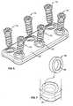
- FIG. 6is a perspective view of the bone plate system of FIG. 2 with the bone anchors exploded;
- FIG. 7is a perspective view of a portion of the bone plate system of FIG. 4 demonstrating a procedure whereby a pivot base may be seated within a throughbore of the plate;
- FIG. 7Ais a step from the procedure of FIG. 7 ;
- FIG. 7Bis a step from the procedure of FIG. 7 ;
- FIG. 7Cis a step from the procedure of FIG. 7 ;
- FIG. 7Dis the end of the procedure of FIG. 7 with the pivot base seated within the throughbore of the plate;
- FIG. 8is a perspective view of the plate of the bone plate system of FIG. 2 ;
- FIG. 9is a perspective view of a pivot base of the bone plate system of FIG. 2 ;
- FIG. 10is a cross-sectional side view of the pivot base of FIG. 9 ;
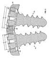
- FIG. 11is a perspective view of a bone anchor of the bone plate system of FIG. 2 ;
- FIG. 12is a side view of the bone anchor of FIG. 11 ;
- FIG. 13is a top view of the bone anchor of FIG. 11 ;
- FIG. 14is a perspective view of another bone plate system embodying features in accordance with the present invention.
- FIG. 15is a top view of the bone plate system of FIG. 14 with bone anchors removed;
- FIG. 16is a perspective view of a pivot base of the bone plate system of FIG. 14 ;
- FIG. 17is a cross-sectional side view of a portion of the bone plate system of FIG. 14 ;
- FIG. 18is a perspective view of a portion of the bone plate system of FIG. 14 wherein the plate has been represented as transparent for the purpose of showing detail;
- FIG. 18Ais a perspective view of a portion of the bone plate system of FIG. 14 showing a step of a procedure whereby a pivot base may be seated within a throughbore of the plate;
- FIG. 18Bis a step of the procedure of FIG. 18A ;
- FIG. 18Cis a step of the procedure of FIG. 18A ;
- FIG. 18Dis the end of the procedure of FIG. 18A with the pivot base seated within the throughbore of the plate;
- FIG. 19is a perspective view a bone plate system embodying features in accordance with the present invention.
- FIG. 20is a perspective view of the plate of the bone plate system of FIG. 19 ;
- FIG. 21is a top view of the bone plate system of FIG. 19 with the bone anchors removed;
- FIG. 22is a perspective view of a portion of the plate of FIG. 20 ;
- FIG. 23is a perspective view of a bone plate system embodying features in accordance with the present invention.
- FIG. 24is a side view of the bone plate system of FIG. 23 ;
- FIG. 25is an end view of the bone plate system of FIG. 23 ;
- FIG. 26is a top view of the bone plate system of FIG. 23 with the bone anchors removed;
- FIG. 27is a perspective view of a bone plate system embodying features in accordance with the present invention.
- FIG. 28is a top view of the bone plate system of FIG. 27 ;
- FIG. 29is a top view of the plate of the bone plate system of FIG. 27 ;
- FIG. 30is a perspective view of a bone plate system having features in accordance with the present invention.
- FIG. 31is a perspective view of the bone plate system of FIG. 30 with the bone anchors removed and the pivot bases exploded;
- FIG. 32is a top view of the bone plate system of FIG. 30 ;
- FIG. 33is a top view of the plate of the bone plate system of FIG. 30 ;
- FIG. 34is a perspective view of a driver for driving bone anchors into bone, the driver having a bone anchor attached thereto and the driver embodying features in accordance with another aspect of the present invention
- FIG. 35is a perspective view of the driver of FIG. 34 with the compression sleeve advanced and the compression jaw and bone anchor head portion compressed;
- FIG. 36is a side view of the driver and the bone anchor of FIG. 34 ;
- FIG. 37is a side view of the driver and the bone anchor of FIG. 35 ;
- FIG. 38is a perspective view of a portion of the driver of FIG. 34 with the bone anchor exploded therefrom;
- FIG. 39is a perspective view of a portion of the driver and the bone anchor of FIG. 34 ;
- FIG. 40is a perspective view of a portion of the driver and the bone anchor of FIG. 35 ;
- FIG. 41is a cross-sectional side view of a portion of the driver and the bone anchor of FIG. 34 ;
- FIG. 42is a cross-sectional side view of a portion of the driver and the bone anchor of FIG. 35 ;
- bone plate systemsare disclosed herein for securing a plurality of bones 7 in a desired orientation and arrangement.
- the bone plate systemutilizes a dynamized plate with dynamic throughbores so that bones 7 may compress and shift toward each other, such as with dynamic or dynamized bone plate systems 410 , 510 shown in FIGS. 27 and 30 , respectively.
- bone plate systemsutilize standard plate members with throughbores of the same size, such as with standard or non-dynamized bone plate systems 10 , 110 , 210 shown in FIGS. 2 , 14 , and 19 , respectively.
- the bone plate systemsutilize monoplate or single-row or single screw per vertebral level embodiments, such as with the monoplate bone plate system 310 shown in FIG. 23 .
- a standard bone plate system 10which may assist in the healing and repair of damaged, fractured, or broken bones.
- bones 7are adjacently located vertebrae of a spine 6 spaced from one another by a spinal disc 8 .
- the bone plate system 10may also be used to assist in the healing necessary after trauma has been experienced by the spinal disc 8 and/or a disc 8 has been removed from an intervertebral space.
- the bone plate system 10may be utilized for stabilization and securement when adjacent vertebrae 7 are fused, with or without the assistance of a bone graft between the vertebrae 7 .
- the bone plate system 10may be used to correct and/or relieve symptoms of a variety of spinal disorders, which may include but are not limited to degenerative disorders, disorders induced by trauma, and pinched nerves.
- the present bone plate system 10preferably allows the bones 7 to undergo a certain degree of shifting relative to each other.
- the bone plate system 10is configured to allow the bones 7 to compress in a manner dictated by the bone plate system 10 .
- this shiftingis preferably accommodated by pivotal motion of pivot members such as pivot bases 50 .
- the bone plate system 10generally includes a bone plate member 20 secured to the bones 7 with bone anchors that are, in a preferred form, bone screws 70 .
- the plate member 20includes throughbores 22 formed therein with a generally spherical pivot base 50 secured within each throughbore 22 .
- the bone screws 70have a head portion 72 that may be secured within an opening 52 of the pivot base 50 by an retention mechanism that is inherent to the bone plate system 10 based on the configuration of the head portion 72 and the pivot base 50 .
- the bone plate 20may be provided with curvature in the longitudinal direction that contours the plate member 20 to the average natural curvature of the spine 6 , as well as to reduce interference with surrounding tissues.
- the plate 20may be pre-bent to have a curvature in a longitudinal direction, preferably with a radius of curvature of approximately 200 millimeters, and in a lateral direction, preferably with a radius of curvature of approximately 20 millimeters. It is often desirable to alter the standard shape of the plate 20 to fit an individual patient's unique anatomy. This should be done in a manner so as not to scratch or mar the surfaces of the bone plate 20 , which otherwise may negatively affect the long-term fatigue performance of the plate member 20 .
- a plate bending instrumentmay be used for altering the curvature of the plate 20 when necessary due to a unique anatomy. The plate bender is operated to either increase or decrease the radius of the lordotic curvature of the bone plate 20 .
- the particular embodiment of the present invention shown in FIGS. 1-13is a standard or non-dynamized bone plate system 10 which may be installed within the anterior cervical region of a spinal column 6 .
- the bone plate 20preferably has a curved profile that contours to the vertebral bones 7 for a complimentary fit.
- the bone plate 20may extend generally straight relative to the longitudinal axis of the plate 20 , but as mentioned previously, plate member 20 may be bent to accommodate the desired curvature of a particular segment of the spinal column 6 .
- the bone plate 20features two rows of throughbores 22 forming pairs or sets of throughbores 22 . Each pair of throughbores 22 will allow two bone anchors to be driven into each vertebra 7 .
- Each throughbore 22features a curved inner surface 26 terminating in an upper edge or rim portion 28 and a lower edge or rim portion 29 , the lower rim portion 29 preferably having at least one retention lip 38 which may act to limit the range of motion of a pivot base 50 seated within a throughbore 22 .
- the generally rectangular plate member 20has an upper surface 20 a , a lower bone-contacting surface 20 b , generally straight side portions 20 c , and generally straight end portions 20 d.
- the bone plate 20preferably features rounded edges 20 e to minimize irritation and/or damage to the surrounding tissues.
- a pivot base 50may be seated within each throughbore 22 , and each throughbore 22 preferably features a plurality of access slots 30 to allow the pivot base 50 to enter the throughbore 22 .
- the pivot base 50is inserted in alignment with the insertion notches 30 to allow the pivot base 50 to move past the upper edge or rim portion 28 of the throughbore 22 .
- the curved inner surface 26 of the throughbore 22is complementary to a curved outer profile 56 of the pivot base 50 . In this way, as shown in FIGS.
- the pivot base 50is inserted into the throughbore 22 in alignment with the access notches or insertion grooves 30 and then rotated or rolled into position much like a sphere may be rolled within a spherical pocket.
- the throughbores 22 of the plate 20feature retainment lips 38 that interfere with the pivot base 50 as the pivot base 50 is rolled or rotated into a seated position as shown in FIG. 7D .
- the substantially rigid pivot base 50may be forced past the retainment lip 38 , preferably causing no permanent or plastic deformation to the lip 38 or the pivot base 50 and allowing the pivot base 50 to roll or rotate past the lip 38 and be seated within the throughbore 22 .
- the substantially rigid pivot bases 50may be seated within the throughbores 22 of the substantially rigid plate member 20 and may not be removed unless the pivot base 50 is returned to alignment with the access grooves 30 , which would not be possible if a bone anchor such as a bone screw 70 extended through an opening 52 of a pivot base 50 .
- the concave curvature of the throughbore wall 26 and the convex curvature of the pivot base outer surface 56results in interfering dimensions, meaning that with the pivot base 50 and the plate member 20 being substantially rigid, the pivot base 50 could not be forced out of the throughbore 22 because the upper and lower rim portions 28 , 29 would interfere with the outer surface 56 of the pivot base 50 , as an outer diameter d 3 of the base member 50 is larger than an upper rim diameter d 4 .
- a seated pivot base 50could only be removed from the throughbore 22 by utilizing the access notches 30 .
- the pivot base 50is free to move within the throughbore 22 relative to the plate 20 with the outer surface 56 of the pivot base 50 forming an articulating surface much like a sphere in a spherical pocket along the inner surface 26 of the throughbore 22 .
- the pivot base 50remains substantially within the throughbore 22 and is retained therein by the retention lips 38 , as may be seen in FIG. 5 .
- the dimension d 5 across the throughbore 22 from the edge of one access slot 30 to the edge of the otheris preferably just large enough to allow a clearance fit whereby the pivot base 50 may be slidably inserted and then be spherically engaged or made flush with a portion of the curved inner surface 26 of the throughbore 22 , as seen in FIG. 7B .
- the insertion notches 30preferably extend only approximately halfway down the inner surface 26 of the throughbore 22 so that the generally spherical profile 56 of the pivot base 50 is mated or made flush with the spherical profile 26 of the throughbore 22 and the pivot base 50 is able to be rolled thereon, whereas if the access slots 30 extended through to the bottom surface 20 b of the plate member 20 , the pivot bases 50 could foreseeably be slidably moved within the access notches through the plate 20 and fall out of the other side thereof.
- the pivot base retention lips 38 of the throughbores 22prevent the pivot bases 50 from rotating or pivoting more than a predetermined amount within the throughbores 22 . In this way, a pivot base 50 is free to pivot within the throughbore 22 only until the pivot base 50 contacts the retention lip 38 .
- the pivot base 50is inhibited by the retention members 38 from rotating or rolling such that the base member 50 may be realigned with the insertion notches 30 and come out of a seated configuration with the throughbore 22 and possibly be removed from the plate 20 itself.
- the minimum load required to overcome the retention lip 38 to seat the pivot base 50 within the throughbore 22is greater than the maximum load that is anticipated between the pivot base 50 and the retention lip 38 in other situations such as during transporting of the plate system 10 that may occur prior to the plate being implanted.
- the access notches 30are offset from the retention lips 38 so that the outer surface 56 of the base member 50 may be made flush with the inner surface 26 of the throughbore, the generally spherical surfaces 26 , 56 facilitating rotational motion therebetween.
- the surgeon or clinicianwould receive the plate 20 prior to surgery with the spherical pivot bases 50 already seated within the throughbores 22 (as shown in FIG. 4 ) during the manufacturing and/or packaging process, but it will be appreciated that the pivot bases 50 may be installed within the throughbores 22 at another time prior to securing the plate member 20 to bone 7 with bone screws 70 .
- Each generally spherical pivot base 50preferably defines an opening 52 featuring a sloped inner surface 54 .
- the curved outer profile 56 of the pivot base 50complements curved inner surface 26 of the throughbores 22 of the plate member 20 .
- the bone plate system 10may be secured to vertebrae 7 by bone anchors in the form of bone screws 70 , resulting in the configuration shown in FIG. 1 .
- FIG. 1In a preferred form shown in FIG.
- the curved surface 26 of the throughbore 22defines a generally spherical pocket
- the curved profile or surface 56 of the generally spherical pivot base 50is shaped to be complimentary to this pocket shape, allowing the pivot base 50 to be rolled or rotated within the throughbore 22 much like a sphere within a spherical pocket, thus allowing the pivot base 50 to pivot relative to the plate 20 about all three of the primary axes, primary axes denoting the three mutually perpendicular axes of Cartesian three-dimensional space.
- the spherical pivot base 50is free to rotate within the generally spherical pocket about the central axis of the throughbore 22 .
- the pivot bases 50will be fixed to the screws 70 but may allow some rotational motion within the throughbore 22 relative to the plate member 20 .
- the bone plate 20will impart a degree of torsional resistance to limit spinal mobility, and based on the structural, mechanical, and material characteristics of the bone plate 20 , relative motion between the coupled vertebrae 7 may be effectively eliminated with the plate 20 secured thereto.
- the bone screw 70features a partially collapsible or compressible head portion 72 having driver engagement slots 74 , bone screw retention surfaces 77 , and compression jaw engagement portions 76 which are actuated by a surgical instrument 910 that contacts compression jaw engagement surfaces 78 .
- the bone screw 70also comprises a threaded shank portion 80 , which may feature a fluted portion 82 to aid in the removal of bone chips as the bone 7 is cut.
- the bone screw 70also comprises a rounded tip 86 , which is characteristic of a self-tapping screw, but it should be noted that a sharper-tipped self-boring screw or any other screw design which employs the compressible head 72 may be used, as well.
- the bone screw 70also features a sloped outer surface 84 which is preferably complimentary to the slopped inner surface 54 of the pivot base 50 . This angled surface inhibits the head portion 72 of the bone screw 70 from driven beyond a predetermined depth relative to the pivot base 50 .
- the central tier 9 b bone screws 70are typically installed generally perpendicular to the face of the bone 7 , and the top tier 9 a and bottom tier 9 c bone screws 70 are often installed at diverging angles, further compressing the coupled vertebrae 7 . As the vertebrae 7 shift and settle during the recovery period, the diverging angles tend to relax.
- the pivot base 50comprises a bone anchor retention lip 58 which contacts the retention surfaces 77 of the bone screw head portion 72 with a retention contact surface 59 of the retention lip 58 .
- the surgical tool 910is configured to compress the screw head 72 in a preferably radial manner which reduces the largest outer diameter of the screw head 72 such that the entire head portion 72 may enter into the opening 52 of the pivot base 50 and clear the retention lip 58 without necessitating contact between the bone screw 70 and the retention lip 58 .
- the compression of the head end 72causes only elastic stress and the head portion 72 at least partially reexpands or returns to an uncompressed configuration when released within the opening 52 of the pivot base 50 , but it will, of course, be appreciated that other forms are possible wherein a combination of elastic and plastic stress is created during the compression of head 72 .
- the surgical tool 910may release the jaw engagement portions 76 , allowing the head portion 72 to expand to form contact between the sloped outer surface 84 of the bone screw 70 and the sloped inner surface 54 of the pivot base 50 .
- the expansion of the screw head 72will cause the head end 72 to be retained within the opening 52 as defined by the sloped surface 54 and the retention lip 58 .
- the bone screw 70will be prevented from backing out of the bone 7 because the bone anchor retention lip 58 will keep the bone anchor head end 72 secured within the pivot base opening 52 when the instrument 910 has released the bone screw head 72 and allowed the head portion 72 to reexpand, causing a largest outer diameter d 1 of the bone anchor head portion 72 to be larger than an entry diameter d 2 of the base member 50 .
- the present inventionprovides an effective and reliable apparatus which inhibits the bone anchors 70 from backing out of bone 7 wherein threaded shank portions 80 of the bone screws 70 are secured.
- this method whereby the bone screw 70 is retainedoffers minimal probability of failure and minimal risk for the pivot bases 50 or the bone screws 70 to come out of the plate member 20 while properly installed during the recovery period.
- the retention surfaces 77 of the bone screw 70 and the retention contact surface 59 of the retention lip 58 of the pivot base 50are configured such that a load wherein the bone screw 70 is pushed toward the retention lip 58 will not compress the head portion 72 and allow the bone screw 70 to back out of the opening 52 of the pivot base 50 .
- the substantially rigid pivot bases 50are prevented from being removed from the substantially rigid bone plate 20 by virtue of the interfering dimensions therebetween, and the bone anchors 70 may not be removed from the pivot bases 50 without the aid of a specialized bone anchor driving apparatus such as the surgical tool or driver 910 .
- the driver 910comprises a jeweler's knob 922 which is connected to a handle portion 920 by a thrust bearing (not shown).
- the handleis connected to a shaft 960 , and in a preferred form the shaft 960 is fabricated as a single piece comprising a handle engagement portion 962 , a cam engagement portion 964 , a concentric portion 966 , and a screw head engagement cross 968 .
- the cam engagement portion 964 of the shaft 960is pinned to a compression shaft actuation lever or toggle-action cam lock 930 by a pin 980 . As shown in FIGS.
- the lever 930preferably features a grip portion 932 , a relaxed or retraction engagement cam surface 934 , and a compression or advancement engagement cam surface 936 .
- the concentric portion 966 of the shaft 960is generally housed within and is generally concentric with a compression shaft or sleeve 940 .
- the compression shaft 940may feature a plurality of apertures 946 which offer a partial view of the concentric portion 966 of the shaft 960 .
- a compression jaw 950housed at least partially within the compression shaft 940 and at least partially retained by the engagement cross 968 is a compression jaw 950 .
- the compression jaw 950is first joined to shaft 960 such as by laser welding or the like. The compression shaft 940 is then slid over the compression jaw 950 and onto the shaft 960 .
- An engagement portion 956 of the compression jaw 950is formed to engage the engagement portion 76 of the bone screw head portion 72 .
- the driver 910may further feature a biasing member (not shown) such as a spring housed between the compression shaft 940 and the concentric portion 966 of the central shaft 960 to bias the compression shaft 940 toward the handle 920 with the lever or cam lock 930 moved to the relaxed or compression shaft retraction orientation shown in FIG. 36 .
- a biasing membersuch as a spring housed between the compression shaft 940 and the concentric portion 966 of the central shaft 960 to bias the compression shaft 940 toward the handle 920 with the lever or cam lock 930 moved to the relaxed or compression shaft retraction orientation shown in FIG. 36 .
- the compression jaw 950may by itself produce a biasing load sufficient to bias the compression shaft 940 toward the handle portion 920 with the lever or cam lock 930 moved to the relaxed or retraction orientation shown in FIG. 36 .
- a surgeon or clinicianwould engage the bone screw with the driver 910 as it appears in FIG. 34 .
- the engagement cross 968engages the driver engagement ridges 74 of the bone screw 70
- the compression jaw 950surrounds the compression jaw engagement portions 76 .
- the surgeonmay use the grip portion 932 to toggle the switch 930 to the compression position seen in FIG. 35 .
- the lever 930transitions from abutting the compression sleeve 940 with the relaxed or retention cam surface 934 to abutting the compression sleeve 940 with the compression or advancement cam surface 936 , and thus the cam lock 930 causes the compression sleeve 940 to translate down the shaft 960 , compressing the jaw 950 and causing the engagement portion 956 to compress the resilient screw head portion 72 .
- the knob 922 and the handle 920are preferably linked by a thrust bearing (not shown) allowing the knob 922 to remain stationary relative to the handle 920 as the handle 920 and shaft rotate in kind with one another.
- the shaft 960is connected to the handle 920 such that as the handle 920 is rotated, the shaft 960 rotates, as well. In this way, the surgeon may hold the jeweler's knob 922 in the palm of his or her hand and rotate the handle 920 with his or her fingers.
- the screw 70is connected to the engagement cross 968 , the cam lock 930 is transitioned to the advancement orientation seen in FIG. 37 , causing the compression sleeve 940 to translate and compress the jaw member 950 , compressing the resilient bone screw head 72 .
- the compression member 950acts to retain the bone screw 70 to the driver 910 such that the bone screw 70 and driver 910 may together be moved over the surgical site and directed toward the bone anchor insertion point with minimal risk that the bone screw 70 will come out of engagement with the driver 910 .
- the jaw 950serves to temporarily secure the bone anchor 70 to the driver 910 , as a conventional driver may rely on solely engaging the engagement slots 74 which could either be ineffective in securing the bone screw 70 to the driver or engage the bone screw 70 effectively filling the engagement slots 74 such that the bone screw head portion 72 could not be compressed to clear the bone anchor retention member 58 and enter the pivot base opening 52 .
- the present driver 910is preferably configured such that the engagement cross portion 968 may create sufficient torque to drive the bone anchor 70 but leave space to allow the bone screw head portion 72 to be compressed, utilizing the jaw 950 not only to compress the screw head 72 but to aid in retaining the bone screws 70 to the driver 910 .
- the surgeonmay install the bone screw 70 into bone 7 in any desired orientation within a range of permissible orientations allowed by the plate member 20 and the pivot base 50 .
- the compression of the bone screw head end 72 by the compression jaw 950preferably allows the bone anchor member 70 to clear and pass by the head portion retention lip 58 , and with the bone screw 70 is in a seated configuration, the cam lever 930 may be toggled to the retraction position to allow the resilient screw head 72 to at least partially reexpand within the pivot base opening 52 .
- This toggle actioncauses the compression shaft or sleeve 940 to translate relative to the central shaft member 960 once more as the compression shaft 940 returns to the configuration shown in FIG.
- the plate member 20 and any other bone plate member in accordance with the present inventionmay feature a plurality of bone pin holes (not shown) for inserting bone pins (not shown) into bone for temporarily restraining the bone plate in a desired location and orientation prior to driving bone anchors into bone to secure the plate member thereto.
- the bone pin holesmay be placed at opposite and/or diagonal ends of the bone plate.
- a rescue screw(not shown) may be provided for securing the plate member to bone.
- a rescue screwis a screw that has a larger thread diameter, or a larger central or minor diameter, or both relative to conventional bone screws when secured within bone. The larger dimensions create a degree of interference with the bone and as such, the rescue screw is able to gain purchase in a stripped hole, treating the hole as if it were merely a pilot hole because of the larger size of the rescue screw.
- FIGS. 14-18another embodiment having features according to the present invention is shown.
- discussion pertaining to this and subsequent embodimentswill be discussed primarily in light of how the embodiments differ from the bone plate system 10 shown in FIGS. 1-8 .
- the surgical instrument 910is configured for use with all bone plate system embodiments and pivot base concepts that are shown for exemplary purposes herein.
- FIG. 14shows a bone plate system 110 comprising a bone plate 120 , which is similar in many respects to the plate 20 discussed previously with the exception that the plate member 120 features pivot bases 150 with protrusions or extended members in the form of pegs or posts 160 .
- the pivot bases 150are configured to be recieved within throughbores 122 and the pegs 160 are configured to fit within peg access slots 140 adjoined to the main throughbore portion 122 .
- the post insertion cavities 140have an end wall that is preferably substantially vertical with a curved profile as seen in FIGS.
- the pivot bases 150feature an opening 152 through which a bone screw 70 may pass in much the same manner described above with respect to the pivot base 50 of the previously discussed bone plate system 10 .
- the extended members 160are in general alignment with the longitudinal axis of the plate 120 and, in a preferred form, inhibit the pivot base 150 from rotating about the central axis of the throughbore 122 . This is in contrast to the previous bone plate system 10 discussed above in which the pivot bases 50 are free to rotate about the central axis of the throughbores 22 until the bone screw 70 is driven into bone 7 and seated with the screw head portion 72 is allowed to expand within the opening 52 and form a tight fit between the complimentary sloped surfaces 54 , 84 of the pivot base 50 and bone screw 70 , respectively. It should be noted that features that are similar to features of the previously discussed bone plate system 10 may be denoted in a similar manner, such as throughbores 22 and 122 and pivot bases 50 and 150 .
- the posts 160In addition to inhibiting the pivot base 150 from rotating about the central axis of the throughbore 122 , the posts 160 also limit the range through which the pivot bases 150 may pivot fore and aft relative to the longitudinal axis of the plate member 120 .
- the pivot base 150is more limited in this range of motion relative to the pivot base 50 because a post member 160 on one side of the base member 150 will contact the bone and inhibit further pivoting in that angular direction.
- the extended members 160may limit the amount that the screw 70 and pivot base 150 may pivot relative to the plate 120 .
- the pegs 160also allow the system 110 to impart more torsional resistance to inhibit movement of the coupled vertebrae.
- the plate 120will impart some resistance when the patient attempts to move the coupled vertebrae relative to one another, but the pegs 160 further hinder this motion.
- the previously discussed system 10featured spherical pivot bases 50 that did not have pegs or posts, and in this way the pivot base 50 could rotate slightly about the central axis of the throughbore 22 .
- the system 110 featuring the generally spherical pivot base 150 with projecting members 160will not allow such rotation about the central axis of the throughbore 122 , and as such the system 120 will provide more substantial torsional resistance to attempted movement of the coupled vertebrae.
- This mechanical characteristicwill be discussed in greater detail below as it relates to monoplate (single-row or single screw per vertebral level as opposed to double-row or dual screws per level) embodiments of the present invention.
- the present pivot base 150also features a curved outer profile 156 which is complementary to a curved inner surface 126 of the throughbore 122 .
- the throughbore 122also features an upper edge portion 128 and a lower edge portion 129 .
- the preferably spherical complementary surfaces 126 , 156allow the pivot base 150 to pivot within the throughbore 122 about the two primary axes not constrained by the extended members 160 .
- the pivot base 150is free to pivot about the longitudinal axes of the posts 160 , with the extended members 160 acting as pivot members and the surface 156 articulating relative to the inner surface 126 of the throughbore 122 , this pivotal motion being limited by at least one pivot base retention lip 138 near the lower edge portion 129 of the throughbore 122 . Should the pivot base 150 pivot to a predetermined limit, the base 150 will contact the retention lip 138 , which will inhibit further pivoting in that particular direction.
- the pivot base 150is also free to pivot such that one of the pegs 160 moves up relative to the bone 7 120 while the other moves down relative to the bone 7 , this motion being inhibited should a peg member 160 pivot into contact with a bone 7 or the pivot base 150 contact a retention lip 138 .
- the pivot base 150could also pivot both fore and aft and side to side with respect to the longitudinal axis of the plate member 20 at the same time.
- the pivot base 150preferably does not rotate about the central axis of the throughbore 122 beyond a predetermined amount of play provided within the peg slots 140 . In a preferred embodiment, very little to no play is provided between the posts 160 and the side walls 144 of the post access grooves 140 , but it is, of course, possible that in alternative embodiments a larger predetermined range of play may be allowed.
- the pivot base 150also features slightly rounded surfaces 162 at the ends of the extended members or posts 160 .
- the surfaces 162allow for the pivoting motion whereby the pegs 160 may contact the bone 7
- an end surface 142 of the access cavity 140is generally vertical with respect to the central axis of the throughbore 122 , but features a curved profile the account for the curvature of the ends 162 of the extended member 160 and allow relative motion thereby.
- the pivot base 150is installed using a method similar to the method whereby pivot bases 50 are installed within throughbores 22 in the system 10 discussed above. As shown in FIGS.
- the pivot base 150is slidably inserted or translated into the throughbore 122 such that the posts 160 are slidably inserted into the slots 140 with the orientation of the pivot base 150 preferably approximately perpendicular to the orientation seen in FIG. 14 .
- the pivot base 150may be rolled or rotated into a seated orientation. As with the previous bone plate system 10 , seating the pivot base 150 requires that the pivot base 150 be forced to overcome interference between the pivot base 150 and the retention lip 138 of the throughbore 122 , preferably causing only elastic stress to the retention lip 138 and/or pivot base 150 .
- This configurationwill inhibit the spherical pivot base 150 from pivoting beyond a predetermined range while properly seating and securing the pivot base 150 within the throughbore 122 by virtue of the rigidity of the plate member 120 and the pivot base 150 and the interfering spherical geometry and dimensions therebetween.
- the minimum design load required to force the pivot base 150 past the lip 138will be greater than the maximum load that the lip 138 and pivot base 150 are predicted to be subjected to under any other expected conditions during the recovery period.
- FIGS. 19-22another embodiment according to the present invention is shown in the form of a standard or non-dynamized bone plate system 210 .
- the present system 210preferably utilizes the same pivot bases 150 and bone screws 70 as the previously discussed system 110 and is used in much the same manner as the previous system 110 .
- the pivot bases 150are preferably installed in the same manner and must be forced past at least one retainment lip 238 featured within a throughbore 222 .
- the present bone plate system 210may offer several advantages that are a result of the utilization of a bone plate 220 , which offers similar structural performance and mechanical characteristics to the previous plate member 120 , but includes apertures 232 , end impressions 233 , and side impressions 234 .
- the impressions 233 , 234allow the surgeon to view more of the spine 6 , and the apertures 232 offer the ability to view more of the spinal discs 8 or bones 7 during surgery.
- This enhanced view of the surgical sitemay allow a surgeon greater ability to choose optimal placement for the plate member 220 and may also allow a surgeon to view areas of a fusion or graft site, intervertebral space, or spinal injury in an advantageous manner.
- the apertures 232may also allow a surgeon or clinician to perform operations within the intervertebral space using a cannula or other minimally invasive instrument extending through an aperture 232 and into the intervertebral space.
- the reduced cross-section between tiers due to the apertures 232 and side impressions 234may cause the segments between throughbores 222 to be easier to bend should a patient require the plate member 220 to contour present or desired spinal curvature, which is advantageous because bending the bone plate 220 at the throughbores 222 could compromise the intended geometric configuration and/or mechanical characteristics of the plate member 220 , the throughbores 222 , and the pivot bases 150 .
- apertures and/or impressionssuch as the apertures 232 or impressions 233 , 234 are not shown as a feature all embodiments disclosed herein for exemplary purposes, it will of course be appreciated that and/or impressions may be incorporated a features of any bone plate systems described herein or any other possible embodiments incorporating features according to the present invention.
- the present bone plate system 310may be referred to as monoplate as it comprises a plate 320 that features only a single screw per vertebral level.
- plate 320preferably has only one set or row of throughbores 322 or one throughbore 322 per tier, not paired sets of throughbores as seen in the bone plate systems 10 , 110 , 210 discussed above.
- the monoplate system 310also employs the pivot bases 150 comprising pegs or posts 160 .
- the monoplate 320preferably features a curved profile similar to that of the previously discussed embodiments so that it may contour to the face of a vertebra 7 .
- a surgeon choosing to utilize the bone plate system 310will install only one such system 310 , and the surgeon may install the system 310 centrally with respect to the anterior cervical region of the vertebral column 6 or the present bone plate system 310 may be installed such that the plate member 320 is positioned off-of-center with respect to the midsagittal plane. Such a decision would be a factor of the individual case of the patient and the preference of the surgeon, but some surgeons may install the bone plate system 310 off-of-center to ensure that the bone plate system 310 poses minimal interference to normal swallowing motions and avoids agitating or damaging the esophagus.
- the curved profile of the plate 320allows a favorable contour to the bone 7 regardless of the surgeon or clinician's preference of a centered or off-of-center placement of the bone plate system 310 .
- the narrower profile of the plate member 320may allow the present system 310 to be installed with a smaller incision, which may lead to less discomfort and/or a faster recovery.
- the single-row configurationrequires fewer bone anchors and thus the surgery to secure the plate member 320 to bone 7 may be less time-consuming.
- a smaller plate profileis also less prone to inhibit swallowing and/or impede on the esophagus and other soft tissues.
- the narrower plate member 320is thus less likely to irritate the esophagus and other tissues, decreasing the probability of complications such as esophageal dysphagia or other possible side-effects known to occur as a result of the presence of an anterior cervical plate.
- the narrower plate member 320will not by itself offer the torsional resistance of the wider two-rowed plate members discussed above, but the extended members 160 of the pivot bases 150 will enhance the torsional resistance of the monoplate bone plate system 310 such that relative movement of the coupled vertebrae 7 is sufficiently inhibited.
- the posts 160extend between the extended straight side portions 344 of the access slots 340 , thus the pivot bases 150 are inhibited from rotating about the central axes of the throughbores 322 and thus the posts 160 contacting the extended side walls 342 of the peg slots 340 will serve to add to the torsional resistance supplied by the bone plate system 310 and inhibit rotation of the secured vertebrae 7 relative to one another.
- the pegs 160allow the bone plate system 310 to offer sufficient torsional stability to be used without employing less elegant methods for attempting to increase torsional stability such as bone-engaging spikes that can be pressed into the face of a bone and may damage osseous tissue.
- FIGS. 27-29another embodiment according to the present invention is shown in the form of a dynamic bone plate system 410 .
- the dynamic bone plate system 410is similar in many respects to the previously discussed bone plate system 10 in that the present bone plate system 410 comprises a generally rectangular plate member 420 , generally spherical pivot bases 50 , and bone screws 70 , but the present plate member 420 features both standard 422 and dynamized 423 , 424 throughbores.
- the bone 7 that the surgeon desires to stabilizesuch as, for example, a vertebrae 7 that has been injured or features a bone graft, will be aligned with the standard throughbores 422 , and the adjacent vertebra 7 will be aligned with elongated, dynamized throughbores 423 .
- the throughbore 423has the same width as the diameter of the generally circular through throughbore 422 , but the dynamized throughbore 423 is elongated to allow the pivot base 50 to translate a predetermined distance relative to the plate 420 within the throughbore 423 , and, in a preferred form, the predetermined length of translation is approximately 1.25 millimeters, though it will be appreciated that it could be any other length according to the needs of the patient or the preference of the surgeon.
- the next vertebra 7one removed from the stationary throughbores 422
- will be aligned with longer elongated throughbores 424which preferably allow approximately two times the length of possible translation of the intermediate throughbores 423 .
- the longer elongated throughbores 424allow twice the length of translation of the intermediate elongated throughbores 423 because the longer elongated throughbores 424 account for relative motion between both the first and second and the first and third vertebra 7 .
- the dynamized plate member 420will be secured such that the standard throughbores 422 are aligned with the uppermost secured vertebrae 7 and the dynamized throughbores 423 , 424 are aligned with the next two vertebrae 7 moving down the spine 6 .
- the bone anchors 70are installed at far ends 423 a , 424 a within the elongate throughbores 423 , 424 .
- the bone anchors 70 within the dynamized throughbores 423 , 424generally tend to translate relative to the plate member 420 within the throughbores moving closer to the standard or non-dynamized throughbores 422 .
- the second pair elongated of throughbores 424 moving away from the standard pair 42allows twice the translation of the first pair of elongated or dynamized throughbores 423
- further embodimentsare possible which may feature four or even five or more pairs of throughbores.
- the fourth pair of throughbores of the plate memberwould preferably allow three times the length of translation that the second pair of throughbores 423 allows and the fifth pair of throughbores would preferably allow four times the length translation that the second pair of throughbores 423 allow.
- a choice regarding the number of pairs of throughbores on a bone plateis dependent on the type and severity of the injury, the number of vertebrae 7 being fused, the needs of a particular patient, and/or the preferences of a surgeon or specialist.
- vertebrae 7may shift or move closer together during the healing, grafting, and/or fusion process.
- the screws 70 driven into bones 7may pivot relative to the plate member by way of the spherical pivot bases to accommodate the relative movement of the bones 7 .
- this movementmay be accounted for by both pivoting and translation.
- the type of bone plate system chosen—standard or dynamic—is dependent on the type and severity of the injury, the number of vertebrae being fused, the expected amount of vertebral settling, and/or the preferences of the surgeon or specialist. In some cases, a surgeon may believe that the pivoting would be sufficient to accommodate the expected degree of shifting and/or changes in curvature.
- pivotingalone may not accommodate the expected shifting and/or changes in curvature and translation of the pivot bases 50 relative to the plate may be necessary, as well. If a surgeon believes that the recovery period may entail more movement between adjacent vertebrae than pivotal motion alone could accommodate, a bone plate system employing dynamized throughbores will generally be utilized. In these cases, the pivoting capability remains quite important and may still account for a portion of the vertebral settling, but the translational capability may be of primary importance, as well.
- the dynamized bone plates system 410 shown in FIG. 28preferably has bone screws 70 spaced in the same manner that a surgeon would desire that the bone anchors be spaced immediately following securement to bone 7 .
- Wolff's Lawteaches the positive effects that compression can have upon bone growth and the integrity of a graft or healed injury.
- a surgeonwill attempt to install the bone screws 70 in the elongated throughbores 423 and 424 such that the head portions 72 are placed at far ends 423 a , 424 a and are as far away from standard or non-dynamized throughbores 422 as possible while keeping all vertebrae 7 that are coupled to the bone plate 420 in compression such that the coupled vertebrae 7 will remain in compression as the region heals.
- the elongated throughbores 423 , 424will allow the bone screws 70 and generally spherical pivot bases 50 to have a predetermined range of pivotal and translational motion in accordance with shifts, settling, and/or changes in curvature within the vertebral column 6 .
- the pivot bases 50 within the dynamized throughbores 423 , 424may translate within the throughbores 423 , 424 toward the standard pair of throughbores 422 as the vertebrae 7 shift or settle.
- the elongationsatisfies the geometric requirements for which the access or insertion grooves 430 are provided on the standard throughbores 422 , and the retention lips 438 serve to retain the pivot bases 50 within their corresponding throughbores as the pivot bases 50 are thereby inhibited from rotating or rolling into a position wherein they may be removed from a seated configuration.
- the elongated throughbores 423 , 424further inhibit the pivot bases 50 from rolling out of the seated or retained configuration when a bone screw 70 is installed within a vertebra 7 and the bone screw head end 72 is seated and reexpanded within the opening 52 of the pivot base 50 and is retained therein by the retention lip 58 .
- the dynamic system 510comprises a bone plate member 520 that is similar in some respects to the plate member 220 from the previously discussed standard or non-dynamized bone plate system 210 .
- the plate member 520features apertures 532 , end impressions 533 , and side impressions 534 which are similar to the apertures 232 and impressions 233 , 234 featured on the previous bone plate member 220 .
- the bone plate 520comprises three pairs of throughbores, and in the present system 510 the central pair are standard, non-dynamized throughbores 522 featuring peg slots or cavities 540 , as the throughbores 522 are configured to accommodate the generally spherical pivot bases 150 with extended members 160 discussed above.
- the two pairs of throughbores adjacent to the standard throughbores 522feature dynamized throughbores 523 configured to accommodate the spherical pivot bases 50 that may pivot within the throughbores 523 about all three primary axes as defined above.
- the throughbores 523allow generally the same lengths of translation as the dynamized throughbores 423 would allow in the dynamic bone plate system 410 described above, which may be approximately 1.25 millimeters for example.
- the present dynamic bone plate system 510is shown with only three pairs of throughbores, it will of course be appreciated that other embodiments having two, four, or even five or more sets of throughbores may be possible.
- the throughbores disposed progressively further away from the standard, non-dynamized pair of throughbores 522would preferably allow progressively greater lengths of translation in the direction generally parallel to the longitudinal axis of the bone plate.
- the standard, non-dynamized pair of throughbores 522may feature the pivot bases 150 with extended members or pegs 160 while the dynamized sets of throughbores may feature the spherical pivot bases 50 that do not feature extended members.
- the standard throughbores 522 of the system 510will feature access slots or cavities 540 to accommodate the use of pivot bases 150 comprising extended members 160 .
- the spherical pivot bases 150will preferably be seated in the same manner described above with respect to the standard bone plate system 110 .
- the extended posts or pegs 160serve to add to the torsional resistance of the plate member 520 in the region of the stationary vertebra 7 as well as limit the range through which the pivot bases 150 may pivot, as the posts 160 will eventually contact the bone 7 if pivoted far enough and the pivot base 150 is inhibited from rotating about one of the three primary axes.
- a pivot base with extended members such as the pivot base 150In a dynamized or dynamic throughbore such as the dynamized or elongated throughbores 523 , it is not preferable to use a pivot base with extended members such as the pivot base 150 because the extended members 160 could restrict the desired range of motion. In a standard, non-dynamized throughbore 522 of the present dynamic bone plate system 510 however, a pivot base with extended members such as the pivot base 150 may be preferred.
- the spherical pivot bases 150 placed in the standard throughbore 522will resist torsional stress and will not be free to rotate about the central axis of the throughbores 522 , but the other spherical pivot bases 50 without extended members 160 that are seated within the elongated throughbores 523 are free to undergo pivotal and translational motion as well and rotate about the central axis of the throughbore 523 .
- the dynamic bone plate systems 410 and 510may employ a retainer or guide (not shown) during the installation of the bone screw 70 in a dynamized throughbore 423 , 424 , 523 that would hold the pivot base 50 within the throughbore in a particular orientation and aid the surgeon or clinician in spacing the pivot bases 50 to the farthest removed ends 423 a , 424 a , 523 a from the standard, non-dynamized pair of throughbores 422 , 522 .
- a retainer or guide(not shown) during the installation of the bone screw 70 in a dynamized throughbore 423 , 424 , 523 that would hold the pivot base 50 within the throughbore in a particular orientation and aid the surgeon or clinician in spacing the pivot bases 50 to the farthest removed ends 423 a , 424 a , 523 a from the standard, non-dynamized pair of throughbores 422 , 522 .
- a guide or retainerwould aid the surgeon in creating optimal spacing between pivot bases 50 and insert the bone anchors 70 while allowing greater control over the bone anchor insertion trajectories so that the bone anchors 70 may be driven into bone 7 in the most desirable insertion angles.
- a plurality of guidesoffering various angles of trajectory or a single guide (not shown) which may be adjustable to any angle within a predetermined range of angles or to any of a predetermined set of available angles may be available.
- the materials to be used for the bone plate systems 10 , 110 , 210 , 310 , 410 , 510 described abovemust be sufficiently strong and demonstrate desirable mechanical characteristics while also fulfilling other requirements such as biocompatibility and galvanic corrosion considerations.
- the bone plate members 20 , 120 , 220 , 320 , 420 , 520may be composed at least partially of titanium, a titanium alloy, polyetheretherketone (PEEK), or carbon-fiber PEEK composite.
- the pivot base members 50 , 150may be composed at least partially of titanium, a titanium alloy, or cobalt-chrome alloy.
- Bone anchor members such as the bone screws 70may be composed at least partially of titanium or titanium alloy.
Landscapes
- Health & Medical Sciences (AREA)
- Orthopedic Medicine & Surgery (AREA)
- Life Sciences & Earth Sciences (AREA)
- Surgery (AREA)
- Medical Informatics (AREA)
- Engineering & Computer Science (AREA)
- Biomedical Technology (AREA)
- Heart & Thoracic Surgery (AREA)
- Nuclear Medicine, Radiotherapy & Molecular Imaging (AREA)
- Molecular Biology (AREA)
- Animal Behavior & Ethology (AREA)
- General Health & Medical Sciences (AREA)
- Public Health (AREA)
- Veterinary Medicine (AREA)
- Neurology (AREA)
- Surgical Instruments (AREA)
- Prostheses (AREA)
Abstract
Description
Claims (34)
Priority Applications (2)
| Application Number | Priority Date | Filing Date | Title |
|---|---|---|---|
| US12/199,321US8361126B2 (en) | 2007-07-03 | 2008-08-27 | Bone plate system |
| US13/747,131US9655665B2 (en) | 2007-07-03 | 2013-01-22 | Bone plate systems |
Applications Claiming Priority (3)
| Application Number | Priority Date | Filing Date | Title |
|---|---|---|---|
| US94787307P | 2007-07-03 | 2007-07-03 | |
| US96823307P | 2007-08-27 | 2007-08-27 | |
| US12/199,321US8361126B2 (en) | 2007-07-03 | 2008-08-27 | Bone plate system |
Related Child Applications (1)
| Application Number | Title | Priority Date | Filing Date |
|---|---|---|---|
| US13/747,131DivisionUS9655665B2 (en) | 2007-07-03 | 2013-01-22 | Bone plate systems |
Publications (2)
| Publication Number | Publication Date |
|---|---|
| US20090062862A1 US20090062862A1 (en) | 2009-03-05 |
| US8361126B2true US8361126B2 (en) | 2013-01-29 |
Family
ID=40408692
Family Applications (2)
| Application Number | Title | Priority Date | Filing Date |
|---|---|---|---|
| US12/199,321Expired - Fee RelatedUS8361126B2 (en) | 2007-07-03 | 2008-08-27 | Bone plate system |
| US13/747,131Expired - Fee RelatedUS9655665B2 (en) | 2007-07-03 | 2013-01-22 | Bone plate systems |
Family Applications After (1)
| Application Number | Title | Priority Date | Filing Date |
|---|---|---|---|
| US13/747,131Expired - Fee RelatedUS9655665B2 (en) | 2007-07-03 | 2013-01-22 | Bone plate systems |
Country Status (1)
| Country | Link |
|---|---|
| US (2) | US8361126B2 (en) |
Cited By (31)
| Publication number | Priority date | Publication date | Assignee | Title |
|---|---|---|---|---|
| US20130096633A1 (en)* | 2011-10-14 | 2013-04-18 | Michael Black | Orthopedic Anchor Assembly |
| US8795377B2 (en) | 2010-03-10 | 2014-08-05 | Ossdsign Ab | Implants and methods for correcting tissue defects |
| US20140324108A1 (en)* | 2013-04-24 | 2014-10-30 | Skeletal Dynamics, L.L.C. | Bone plate with transversal slots for receiving a fastener |
| US20140343617A1 (en)* | 2013-04-12 | 2014-11-20 | Alphatec Spine, Inc. | Uniplanar screw assembly and methods of use |
| US9044273B2 (en) | 2013-10-07 | 2015-06-02 | Intelligent Implant Systems, Llc | Polyaxial plate rod system and surgical procedure |
| US9220597B2 (en) | 2013-02-12 | 2015-12-29 | Ossdsign Ab | Mosaic implants, kits and methods for correcting bone defects |
| US9381046B2 (en) | 2007-07-03 | 2016-07-05 | Pioneer Surgical Technology, Inc. | Bone plate system |
| US9421053B2 (en) | 2014-05-08 | 2016-08-23 | Titan Spine, Llc | Implant fixation assemblies having a screw and C-shaped fixation collar |
| US9421041B2 (en) | 2008-09-09 | 2016-08-23 | Marc E. Richelsoph | Polyaxial screw assembly |
| US9451992B2 (en)* | 2010-12-01 | 2016-09-27 | Facet-Link Inc. | Variable angle bone screw fixation arrangement |
| US9456851B2 (en) | 2007-10-23 | 2016-10-04 | Intelligent Implant Systems, Llc | Spinal implant |
| US9463046B2 (en) | 2011-08-22 | 2016-10-11 | Ossdsign Ab | Implants and methods for using such implants to fill holes in bone tissue |
| US9486263B2 (en) | 2009-11-04 | 2016-11-08 | X-Spine Systems, Inc. | Screw implant and system and method for locking a screw in an implant plate |
| US9655665B2 (en) | 2007-07-03 | 2017-05-23 | Pioneer Surgical Technology, Inc. | Bone plate systems |
| US10076416B2 (en) | 2013-02-12 | 2018-09-18 | Ossdsign Ab | Mosaic implants, kits and methods for correcting bone defects |
| US10537666B2 (en) | 2015-05-18 | 2020-01-21 | Stryker European Holdings I, Llc | Partially resorbable implants and methods |
| US10603182B2 (en) | 2015-01-14 | 2020-03-31 | Stryker European Holdings I, Llc | Spinal implant with fluid delivery capabilities |
| US10835388B2 (en) | 2017-09-20 | 2020-11-17 | Stryker European Operations Holdings Llc | Spinal implants |
| US10881519B2 (en) | 2014-08-14 | 2021-01-05 | Ossdsign Ab | Bone implants for correcting bone defects |
| US10898332B2 (en) | 2015-11-24 | 2021-01-26 | Ossdsign Ab | Bone implants and methods for correcting bone defects |
| US11000386B2 (en) | 2015-01-14 | 2021-05-11 | Stryker European Holdings I, Llc | Spinal implant with porous and solid surfaces |
| US11026726B2 (en) | 2012-06-29 | 2021-06-08 | K2M, Inc. | Minimal-profile anterior cervical plate and cage apparatus and method of using same |
| US11039865B2 (en) | 2018-03-02 | 2021-06-22 | Stryker European Operations Limited | Bone plates and associated screws |
| US20210196330A1 (en)* | 2015-09-05 | 2021-07-01 | Life Spine, Inc. | Orthopedic implants with variable angle bone screw locking |
| US11058544B2 (en)* | 2018-10-26 | 2021-07-13 | Howmedica Osteonics Corp. | Minimally invasive shoulder implant and method |
| US11096723B2 (en)* | 2008-10-10 | 2021-08-24 | Globus Medical Inc. | Uniplanar screw |
| US11419728B2 (en)* | 2016-02-16 | 2022-08-23 | Waldemar Link Gmbh & Co. Kg | Implant for reconstructing an acetabulum and at least part of a pelvic structure |
| US20220304824A1 (en)* | 2019-03-07 | 2022-09-29 | Spinal Surgical Strategies, Inc., A Nevada Corporation D/B/A Kleiner Device Labs | Bone graft delivery system and method for using same |
| US11744619B2 (en) | 2018-04-06 | 2023-09-05 | K2M, Inc. | Faceted bone plate |
| US11877779B2 (en) | 2020-03-26 | 2024-01-23 | Xtant Medical Holdings, Inc. | Bone plate system |
| US12440342B2 (en) | 2016-02-16 | 2025-10-14 | Waldemar Link Gmbh & Co. Kg | Implant for reconstructing an acetabulum and at least part of a pelvic structure |
Families Citing this family (33)
| Publication number | Priority date | Publication date | Assignee | Title |
|---|---|---|---|---|
| US9320551B2 (en) | 2007-01-26 | 2016-04-26 | Biomet Manufacturing, Llc | Lockable intramedullary fixation device |
| US9308031B2 (en) | 2007-01-26 | 2016-04-12 | Biomet Manufacturing, Llc | Lockable intramedullary fixation device |
| US9801667B2 (en)* | 2007-12-07 | 2017-10-31 | Nexus Spine, L.L.C. | Instruments, tools, and methods for presson pedicle screws |
| US8303633B2 (en)* | 2007-12-13 | 2012-11-06 | K2M, Inc. | Dynamic anterior vertebral plate |
| US20110054544A1 (en)* | 2009-08-31 | 2011-03-03 | Warsaw Orthopedic, Inc. | System with integral locking mechanism |
| US8496692B2 (en)* | 2009-09-21 | 2013-07-30 | Jmea Corporation | Locking securing member |
| WO2011044917A1 (en)* | 2009-10-13 | 2011-04-21 | Zimmer Gmbh | An orthopedic nail and an orthopedic nail system |
| US8535356B2 (en)* | 2009-11-04 | 2013-09-17 | X-Spine Systems, Inc. | Screw implant and system and method for locking a screw in an implant plate |
| US8603148B2 (en) | 2010-05-07 | 2013-12-10 | Raymond B. Raven, III | System for treating bone fractures |
| US9084636B2 (en)* | 2011-01-10 | 2015-07-21 | Spine Craft, LLC | Surgical plate system and method |
| US8940030B1 (en) | 2011-01-28 | 2015-01-27 | Nuvasive, Inc. | Spinal fixation system and related methods |
| DE102011001251A1 (en)* | 2011-03-14 | 2012-09-20 | Ulrich Gmbh & Co. Kg | implant |
| US9480510B2 (en)* | 2011-03-23 | 2016-11-01 | Spinecraft, LLC | Devices, systems and methods of attaching same to the spine |
| US8771324B2 (en) | 2011-05-27 | 2014-07-08 | Globus Medical, Inc. | Securing fasteners |
| US10149707B2 (en)* | 2011-08-17 | 2018-12-11 | Globus Medical, Inc. | Bone fixation plate system and method |
| EP2719348A1 (en)* | 2012-10-10 | 2014-04-16 | FACET-LINK Inc. | Bone screw fixation assembly protected against excess tightening |
| WO2014072983A1 (en)* | 2012-11-11 | 2014-05-15 | Carbofix Orthopedics Ltd. | Composite implant coating |
| US9138324B2 (en) | 2013-01-24 | 2015-09-22 | Warsaw Orthopedic, Inc. | Expandable spinal implant system and method |
| FR3003155A1 (en)* | 2013-03-14 | 2014-09-19 | Jean Luc Chauvin | OSTEOSYNTHESIS DEVICE |
| WO2015038301A1 (en)* | 2013-09-13 | 2015-03-19 | X-Spine Systems, Inc. | Screw implant and system and method for locking a screw in an implant plate |
| WO2015042392A1 (en) | 2013-09-19 | 2015-03-26 | Zlotolow Dan | Variable angle blade plate system and method |
| WO2016137983A1 (en) | 2015-02-24 | 2016-09-01 | X-Spine Systems, Inc. | Modular interspinous fixation system with threaded component |
| CN104970872B (en)* | 2015-06-02 | 2018-11-27 | 北京纳通科技集团有限公司 | A kind of spinal fixation system |
| US20170303981A1 (en)* | 2016-04-21 | 2017-10-26 | Symmetry Medical Manufacturing, Inc. | Self-retaining screwdriver tip and mating drive feature |
| EP3468491B1 (en)* | 2016-06-09 | 2020-12-09 | Stryker European Holdings I, LLC | Bone screw system |
| US20180050415A1 (en)* | 2016-08-16 | 2018-02-22 | Lincoln Global, Inc. | Torch quick release mechanism |
| IT201700027010A1 (en)* | 2017-03-10 | 2018-09-10 | Sim Soluzioni Innovative Medicali Sagl | Instrument for inserting screws in a osteosynthesis plate |
| US20190105085A1 (en)* | 2017-10-10 | 2019-04-11 | Nexus Spine, LLC | Instruments, Tools, and Methods for PressOn Pedicle Screws |
| DE102018101657A1 (en) | 2018-01-25 | 2019-07-25 | Aesculap Ag | Medical bone screw and implant system |
| US10383675B1 (en)* | 2018-09-05 | 2019-08-20 | Zavation, Llc | Screw retention sleeve |
| US20240335217A1 (en)* | 2021-08-03 | 2024-10-10 | Samuel Patrick Franklin | Animal (non-human) ilial fracture stabilization |
| US11903618B2 (en)* | 2021-08-12 | 2024-02-20 | Additive Implants, Inc. | Angled spinal fixation plate |
| IT202300001239A1 (en)* | 2023-01-27 | 2024-07-27 | Limacorporate Spa | POLYAXIAL SCREW AND ORTHOPAEDIC COMPONENT ASSEMBLY |
Citations (327)
| Publication number | Priority date | Publication date | Assignee | Title |
|---|---|---|---|---|
| US434503A (en) | 1890-08-19 | William corry | ||
| US556642A (en) | 1896-03-17 | Nut-lock | ||
| US872897A (en) | 1907-08-31 | 1907-12-03 | John W Chapman | Nut-lock. |
| US951800A (en) | 1909-11-01 | 1910-03-15 | Henry C Lacey | Nut-lock. |
| US1084680A (en) | 1913-03-05 | 1914-01-20 | Arnold Heinrich Wegener | Nut-lock. |
| US1087797A (en) | 1913-01-08 | 1914-02-17 | Claude C Lowe | Checker-board. |
| US1385780A (en) | 1919-09-10 | 1921-07-26 | Flannery Bolt Co | Staybolt structure |
| US1409157A (en) | 1920-01-20 | 1922-03-14 | Flannery Bolt Co | Stay-bolt structure |
| US1756239A (en) | 1929-02-12 | 1930-04-29 | Paul B Chojnacki | Trailer |
| US1907506A (en) | 1931-06-20 | 1933-05-09 | Delco Remy Corp | Retainer clip |
| US1980336A (en) | 1933-05-17 | 1934-11-13 | Pratt & Whitney Co | Chuck retaining means |
| US2248054A (en) | 1939-06-07 | 1941-07-08 | Becker Joseph | Screw driver |
| US2376768A (en) | 1943-11-19 | 1945-05-22 | Tuerca Victorla | Nonloosening safety nut |
| US2401856A (en) | 1943-05-06 | 1946-06-11 | Automotive Prod Co Ltd | Retaining washer and the like |
| US2580821A (en) | 1950-10-21 | 1952-01-01 | Nicola Toufick | Spring impactor bone plate |
| US2628838A (en) | 1947-01-29 | 1953-02-17 | Daniel F Smalley | Rotary block game apparatus |
| US2780223A (en) | 1955-05-17 | 1957-02-05 | Paul B Haggland | Fracture plate |
| US2877792A (en) | 1956-10-12 | 1959-03-17 | Frank W Tybus | Surge or back flow valve |
| US3100516A (en) | 1959-02-06 | 1963-08-13 | Ingersoll Rand Co | Threaded members locked by expanded tubular locking pin |
| US3244170A (en) | 1962-11-23 | 1966-04-05 | Robert T Mcelvenny | Compression type bone splint |
| DE1949923U (en) | 1966-09-29 | 1966-11-17 | Stahl Schanz Frankfurt Am Main | DOOR FRAME. |
| US3426364A (en) | 1966-08-25 | 1969-02-11 | Colorado State Univ Research F | Prosthetic appliance for replacing one or more natural vertebrae |
| US3534731A (en) | 1967-08-18 | 1970-10-20 | Jean Nicolas Muller | Means for joining parts of fractured bones |
| US3596656A (en) | 1969-01-21 | 1971-08-03 | Bernd B Kaute | Fracture fixation device |
| US3599977A (en) | 1969-03-17 | 1971-08-17 | Marvin Glass & Associates | Rotary block tic-tac-toe board and projectiles |
| US3659595A (en) | 1969-10-22 | 1972-05-02 | Edward J Haboush | Compensating plates for bone fractures |
| US3695259A (en) | 1970-11-10 | 1972-10-03 | Clyde E Yost | Bone plate |
| US3741205A (en) | 1971-06-14 | 1973-06-26 | K Markolf | Bone fixation plate |
| US3842825A (en) | 1973-11-12 | 1974-10-22 | R Wagner | Hip fixation device |
| USRE28841E (en) | 1966-06-22 | 1976-06-08 | Synthes A.G. | Osteosynthetic pressure plate construction |
| US4003376A (en) | 1975-08-25 | 1977-01-18 | Bio-Dynamics, Inc. | Apparatus for straightening the spinal column |
| US4029091A (en) | 1974-08-12 | 1977-06-14 | Von Bezold Gotz Dietrich | Osteosynthesis |
| DE2933141C3 (en) | 1978-10-06 | 1981-12-17 | Gebrüder Sulzer AG, 8401 Winterthur | Anchoring pin for a nail-like sliding surface implant |
| US4334599A (en) | 1980-08-18 | 1982-06-15 | The Bendix Corporation | Disc brake and mounting pin assembly therefor |
| USRE31040E (en) | 1975-04-24 | 1982-09-28 | St. Jude Medical, Inc. | Heart valve prosthesis |
| US4361141A (en) | 1979-07-27 | 1982-11-30 | Zimmer Usa, Inc. | Scoliosis transverse traction assembly |
| US4388921A (en) | 1980-05-28 | 1983-06-21 | Institut Straumann Ag | Device comprising a plate and screws for fastening a plate to a bone |
| FR2519857B1 (en) | 1982-01-19 | 1984-03-23 | Butel Jean | |
| USRE31628E (en) | 1966-06-22 | 1984-07-10 | Synthes Ag | Osteosynthetic pressure plate construction |
| US4473068A (en) | 1982-01-18 | 1984-09-25 | Indong Oh | Trochanteric basket |
| US4484570A (en) | 1980-05-28 | 1984-11-27 | Synthes Ltd. | Device comprising an implant and screws for fastening said implant to a bone, and a device for connecting two separated pieces of bone |
| US4493317A (en) | 1980-11-20 | 1985-01-15 | Synthes Ltd. (U.S.A.) | Surgical compression plate and drill guide |
| US4503848A (en) | 1981-04-08 | 1985-03-12 | Aesculap-Werke Aktiengesellschaft | Osteosynthesis plate |
| FR2435243B1 (en) | 1978-09-07 | 1985-06-28 | Tornier Sa | IMPROVEMENTS IN PLATES FOR OSTEOSYNTHESIS |
| FR2556583B1 (en) | 1983-12-19 | 1986-04-18 | Inst Nat Sante Rech Med | OSTEOSYNTHESIS PLATES FOR BONE DEROTATION, ESPECIALLY FEMORAL DEROTATION |
| EP0179695A1 (en) | 1984-09-26 | 1986-04-30 | Pierre Kehr | Vertebral prosthesis, in particular for cervical vertebrae |
| US4599086A (en) | 1985-06-07 | 1986-07-08 | Doty James R | Spine stabilization device and method |
| EP0251583A2 (en) | 1986-06-23 | 1988-01-07 | Howmedica Inc. | Modular femoral fixation system |
| US4762122A (en) | 1987-02-06 | 1988-08-09 | Barclay Slocum | Device and method for pelvic osteotomy fixation |
| US4771767A (en) | 1986-02-03 | 1988-09-20 | Acromed Corporation | Apparatus and method for maintaining vertebrae in a desired relationship |
| SU1424824A1 (en) | 1987-03-30 | 1988-09-23 | Устиновский Государственный Медицинский Институт | Arrangement for osteosynthesis |
| US4794918A (en) | 1985-05-06 | 1989-01-03 | Dietmar Wolter | Bone plate arrangement |
| US4890845A (en) | 1988-12-15 | 1990-01-02 | Sidney Gatewood | Game apparatus with rotating elements |
| US4892545A (en) | 1988-07-14 | 1990-01-09 | Ohio Medical Instrument Company, Inc. | Vertebral lock |
| US4904261A (en) | 1987-08-06 | 1990-02-27 | A. W. Showell (Surgicraft) Limited | Spinal implants |
| US4905679A (en) | 1988-02-22 | 1990-03-06 | M P Operation, Inc. | Bone fracture reduction device and method of internal fixation of bone fractures |
| US4943292A (en) | 1989-11-08 | 1990-07-24 | National Research Council Of Canada | Plate for broken bone fixation |
| US4955908A (en) | 1987-07-09 | 1990-09-11 | Sulzer Brothers Limited | Metallic intervertebral prosthesis |
| US4957497A (en) | 1984-10-27 | 1990-09-18 | Thomas Hoogland | Device for osteosynthesis |
| US4964403A (en) | 1986-12-19 | 1990-10-23 | Huta Baildon Przedsiebiorstwo Panstwowe Katowice | Stabilizer for the treatment of the fracture of the neck and upper metaphysis of the femur |
| EP0410309A1 (en) | 1989-07-20 | 1991-01-30 | Lutz Biedermann | Stabilising element for bones |
| US5002544A (en) | 1987-12-02 | 1991-03-26 | Synthes (U.S.A.) | Osteosynthetic pressure plate osteosynthetic compression plate |
| US5053036A (en) | 1987-11-03 | 1991-10-01 | Synthes (U.S.A.) | Point contact bone compression plate |
| US5057111A (en) | 1987-11-04 | 1991-10-15 | Park Joon B | Non-stress-shielding bone fracture healing device |
| EP0455255A1 (en) | 1990-05-04 | 1991-11-06 | Witold Ramotowski | A plate-type bone stabilizer |
| US5085660A (en) | 1990-11-19 | 1992-02-04 | Lin Kwan C | Innovative locking plate system |
| US5092320A (en) | 1991-03-19 | 1992-03-03 | Empi, Inc. | Knee brace with magnetic securing means |
| US5108395A (en) | 1989-09-18 | 1992-04-28 | Societe De Fabrication De Materiel Orthopedique - Sofamor | Implant for anterior dorsolumbar spinal osteosynthesis, intended for the correction of kyphoses |
| US5113685A (en) | 1991-01-28 | 1992-05-19 | Acromed Corporation | Apparatus for contouring spine plates and/or rods |
| US5127914A (en) | 1989-02-10 | 1992-07-07 | Calderale Pasquale M | Osteosynthesis means for the connection of bone fracture segments |
| US5127912A (en) | 1990-10-05 | 1992-07-07 | R. Charles Ray | Sacral implant system |
| US5129903A (en) | 1988-06-18 | 1992-07-14 | Luhr Hans Georg | Bone plate |
| US5129899A (en) | 1991-03-27 | 1992-07-14 | Smith & Nephew Richards Inc. | Bone fixation apparatus |
| US5139498A (en) | 1988-10-18 | 1992-08-18 | Astudillo Ley Freddy R | Device for closing sternum in heart surgery |
| US5147360A (en) | 1990-02-19 | 1992-09-15 | Societe De Fabrication De Materiel Orthopedique | Osteosynthesis device for the correction of spinal curvatures |
| US5147361A (en) | 1989-11-29 | 1992-09-15 | Asahi Kogaku Kogyo Kabushiki Kaisha | Vertebral connecting plate |
| US5151103A (en) | 1987-11-03 | 1992-09-29 | Synthes (U.S.A.) | Point contact bone compression plate |
| US5180381A (en) | 1991-09-24 | 1993-01-19 | Aust Gilbert M | Anterior lumbar/cervical bicortical compression plate |
| US5190544A (en) | 1986-06-23 | 1993-03-02 | Pfizer Hospital Products Group, Inc. | Modular femoral fixation system |
| EP0242842B1 (en) | 1986-04-21 | 1993-03-03 | Dietmar Prof. Dr. Wolter | Bone plate arrangement |
| US5234431A (en) | 1991-04-03 | 1993-08-10 | Waldemar Link Gmbh & Co. | Bone plate arrangement |
| US5261910A (en) | 1992-02-19 | 1993-11-16 | Acromed Corporation | Apparatus for maintaining spinal elements in a desired spatial relationship |
| US5269784A (en) | 1991-12-10 | 1993-12-14 | Synthes (U.S.A.) | Screw nut for plate osteosynthesis |
| US5275601A (en) | 1991-09-03 | 1994-01-04 | Synthes (U.S.A) | Self-locking resorbable screws and plates for internal fixation of bone fractures and tendon-to-bone attachment |
| US5304179A (en) | 1993-06-17 | 1994-04-19 | Amei Technologies Inc. | System and method for installing a spinal fixation system at variable angles |
| US5324290A (en) | 1992-09-24 | 1994-06-28 | Danek Medical, Inc. | Anterior thoracolumbar plate |
| US5326206A (en) | 1993-04-19 | 1994-07-05 | Northrop Corporation | Method for compensating for bolt hole misalignment and bolt assemblies therefor |
| US5330535A (en) | 1991-03-07 | 1994-07-19 | Sulzer Brothers Limited | Screw-nut for screwing implants together |
| WO1994017744A1 (en) | 1993-02-05 | 1994-08-18 | Danek Medical, Inc. | Anterior cervical plating system |
| US5344421A (en) | 1993-07-16 | 1994-09-06 | Amei Technologies Inc. | Apparatus and method for adjusting a bone plate |
| US5346492A (en) | 1992-03-30 | 1994-09-13 | Timesh, Inc. | Perforated metallic panels and strips for internal fixation of bone fractures and for reconstructive surgery |
| US5380323A (en) | 1993-06-16 | 1995-01-10 | Advanced Spine Fixation Systems, Inc. | Clamps for spinal fixation systems |
| US5380327A (en) | 1992-12-04 | 1995-01-10 | Waldemar Link Gmbh & Co. | Device for connecting bone fragments by means of a bone plate |
| US5382248A (en) | 1992-09-10 | 1995-01-17 | H. D. Medical, Inc. | System and method for stabilizing bone segments |
| US5397364A (en) | 1993-10-12 | 1995-03-14 | Danek Medical, Inc. | Anterior interbody fusion device |
| US5397363A (en) | 1992-08-11 | 1995-03-14 | Gelbard; Steven D. | Spinal stabilization implant system |
| US5415661A (en) | 1993-03-24 | 1995-05-16 | University Of Miami | Implantable spinal assist device |
| US5423826A (en) | 1993-02-05 | 1995-06-13 | Danek Medical, Inc. | Anterior cervical plate holder/drill guide and method of use |
| US5454769A (en) | 1995-03-09 | 1995-10-03 | Chen; Ping | Wrist and forearm exercise apparatus with improved resistance adjustment device |
| DE4409833A1 (en) | 1994-03-22 | 1995-10-05 | Biedermann Motech Gmbh | Stabilizing device, in particular for stabilizing the spine |
| US5458641A (en) | 1993-09-08 | 1995-10-17 | Ramirez Jimenez; Juan J. | Vertebral body prosthesis |
| US5468242A (en) | 1993-11-19 | 1995-11-21 | Leibinger Gmbh | Form-fitting mesh implant |
| US5478342A (en) | 1994-06-30 | 1995-12-26 | Spinetech, Inc. | Reversible bone screw lock |
| US5486176A (en) | 1991-03-27 | 1996-01-23 | Smith & Nephew Richards, Inc. | Angled bone fixation apparatus |
| WO1996005778A1 (en) | 1994-08-23 | 1996-02-29 | Spinetech, Inc. | Cervical spine stabilization system |
| US5501684A (en) | 1992-06-25 | 1996-03-26 | Synthes (U.S.A.) | Osteosynthetic fixation device |
| FR2726461A1 (en) | 1994-11-07 | 1996-05-10 | Hardy Jean Marie | Compressive osteosynthesis plate for long bones |
| US5520696A (en) | 1994-09-27 | 1996-05-28 | Mitek Surgical Products, Inc. | Bone anchor installation tool |
| US5520690A (en) | 1995-04-13 | 1996-05-28 | Errico; Joseph P. | Anterior spinal polyaxial locking screw plate assembly |
| US5522899A (en) | 1988-06-28 | 1996-06-04 | Sofamor Danek Properties, Inc. | Artificial spinal fusion implants |
| US5527311A (en) | 1991-11-13 | 1996-06-18 | Howmedica Gmbh | Support for the human spine |
| US5534032A (en) | 1993-06-21 | 1996-07-09 | Zimmer, Inc. | Orthopaedic implant assembly |
| US5549612A (en) | 1992-11-25 | 1996-08-27 | Codman & Shurtleff, Inc. | Osteosynthesis plate system |
| US5569247A (en) | 1995-03-27 | 1996-10-29 | Smith & Nephew Richards, Inc. | Enhanced variable angle bone bolt |
| US5571109A (en) | 1993-08-26 | 1996-11-05 | Man Ceramics Gmbh | System for the immobilization of vertebrae |
| US5578034A (en) | 1995-06-07 | 1996-11-26 | Danek Medical, Inc. | Apparatus for preventing screw backout in a bone plate fixation system |
| US5601553A (en) | 1994-10-03 | 1997-02-11 | Synthes (U.S.A.) | Locking plate and bone screw |
| US5603713A (en) | 1991-09-24 | 1997-02-18 | Aust; Gilbert M. | Anterior lumbar/cervical bicortical compression plate |
| US5607428A (en) | 1995-05-01 | 1997-03-04 | Lin; Kwan C. | Orthopedic fixation device having a double-threaded screw |
| US5620443A (en) | 1995-01-25 | 1997-04-15 | Danek Medical, Inc. | Anterior screw-rod connector |
| US5626449A (en) | 1995-09-15 | 1997-05-06 | Hong Kong Disc Lock Company Limited | Wedge-locking fastener assembly with a cammed flange |
| US5647872A (en) | 1991-01-14 | 1997-07-15 | Donald Chow | Spinal support plates |
| US5651651A (en) | 1996-08-16 | 1997-07-29 | Spencer; Paul E. | Tamper resistant fastening assembly and method of use |
| US5653708A (en) | 1992-12-28 | 1997-08-05 | Advanced Spine Fixation Systems, Inc. | Cervical spine rod fixation system |
| US5667513A (en) | 1995-06-07 | 1997-09-16 | Smith & Nephew Dyonics Inc. | Soft tissue anchor delivery apparatus |
| DE19548395A1 (en) | 1995-12-22 | 1997-09-18 | Leibinger Gmbh | Osteosynthesis device |
| US5676703A (en) | 1994-05-11 | 1997-10-14 | Gelbard; Steven D. | Spinal stabilization implant system |
| US5681312A (en) | 1996-05-31 | 1997-10-28 | Acromed Corporation | Spine construct with band clamp |
| US5681311A (en) | 1994-09-15 | 1997-10-28 | Smith & Nephew, Inc. | Osteosynthesis apparatus |
| US5683465A (en) | 1996-03-18 | 1997-11-04 | Shinn; Gary Lee | Artificial intervertebral disk prosthesis |
| US5690631A (en) | 1996-09-11 | 1997-11-25 | Walter Lorenz Surgical, Inc. | Multi-configurable plating system |
| FR2740321B3 (en) | 1995-10-27 | 1997-12-05 | Fuentes Jean Marc | ANTERIOR OSTEOSYNTHESIS DEVICE FOR CERVICAL VERTEBRES |
| US5704936A (en) | 1992-04-10 | 1998-01-06 | Eurosurgical | Spinal osteosynthesis device |
| US5707372A (en) | 1996-07-11 | 1998-01-13 | Third Millennium Engineering, Llc. | Multiple node variable length cross-link device |
| US5709686A (en) | 1995-03-27 | 1998-01-20 | Synthes (U.S.A.) | Bone plate |
| US5713900A (en) | 1996-05-31 | 1998-02-03 | Acromed Corporation | Apparatus for retaining bone portions in a desired spatial relationship |
| US5731275A (en) | 1994-04-05 | 1998-03-24 | Universite De Montreal | Synergistic detergent and disinfectant combinations for decontaminating biofilm-coated surfaces |
| US5735850A (en) | 1995-02-17 | 1998-04-07 | Sulzer Medizinaltechnik Ag | Fastening system for pedicel screws |
| US5735899A (en) | 1994-12-08 | 1998-04-07 | Vanderbilt University | Low profile intraosseous anterior spinal fusion system and method |
| US5735853A (en) | 1994-06-17 | 1998-04-07 | Olerud; Sven | Bone screw for osteosynthesis |
| US5741258A (en) | 1993-01-25 | 1998-04-21 | Synthes (U.S.A.) | Lock washer for bone plate osteosynthesis |
| US5766176A (en) | 1996-09-11 | 1998-06-16 | Walter Lorenz Surgical, Inc. | Formable mesh |
| WO1998034556A1 (en) | 1997-02-11 | 1998-08-13 | Michelson Gary K | Skeletal plating system |
| WO1998034553A1 (en) | 1997-02-11 | 1998-08-13 | Michelson Gary K | Anterior cervical plating system, instrumentation, and method of installation |
| US5797912A (en) | 1995-09-22 | 1998-08-25 | Terray Corporation | Washer for use with a bone screw |
| US5800433A (en) | 1996-05-31 | 1998-09-01 | Acromed Corporation | Spinal column retaining apparatus |
| US5810823A (en) | 1994-09-12 | 1998-09-22 | Synthes (U.S.A.) | Osteosynthetic bone plate and lock washer |
| US5814048A (en) | 1996-05-03 | 1998-09-29 | Sofamor Danek Properties, Inc. | Cranioplasty plates and method of installation |
| US5827285A (en) | 1996-12-12 | 1998-10-27 | Bramlet; Dale G. | Multipiece interfragmentary fixation assembly |
| WO1998051226A2 (en) | 1997-05-15 | 1998-11-19 | Sdgi Holdings, Inc. | Anterior cervical plating system |
| US5840078A (en) | 1995-03-01 | 1998-11-24 | Yerys; Paul | Method and apparatus for mechanical attachment of soft tissue to bone tissue |
| US5843082A (en) | 1996-05-31 | 1998-12-01 | Acromed Corporation | Cervical spine stabilization method and system |
| EP0897697A1 (en) | 1997-05-09 | 1999-02-24 | Spinal Innovations | Spinal fixation plate |
| US5879389A (en) | 1995-04-07 | 1999-03-09 | Koshino; Tomihisa | Medical substituting element for hard tissues and artificial joint |
| EP0903113A2 (en) | 1997-09-09 | 1999-03-24 | Fuchs, Werner | Fixed-angle screw connection for bone plates |
| US5888221A (en) | 1992-08-11 | 1999-03-30 | Gelbard; Steven D. | Spinal stabilization implant system |
| WO1999021502A1 (en) | 1997-10-24 | 1999-05-06 | Bray Robert S Jr | Bone plate and bone screw guide mechanism |
| US5904683A (en) | 1998-07-10 | 1999-05-18 | Sulzer Spine-Tech Inc. | Anterior cervical vertebral stabilizing device |
| US5916200A (en) | 1997-10-01 | 1999-06-29 | Walter Lorenz Surgical, Inc. | Apparatus and method for stabilization of a cranial shunt |
| US5951557A (en) | 1997-12-30 | 1999-09-14 | Luter; Dennis W. | Bone plate |
| US5951558A (en) | 1998-04-22 | 1999-09-14 | Fiz; Daniel | Bone fixation device |
| US5954722A (en) | 1997-07-29 | 1999-09-21 | Depuy Acromed, Inc. | Polyaxial locking plate |
| US5964762A (en) | 1996-09-17 | 1999-10-12 | Biedermann; Lutz | Bone plate |
| US5976141A (en) | 1995-02-23 | 1999-11-02 | Synthes (U.S.A.) | Threaded insert for bone plate screw hole |
| US5980540A (en) | 1997-04-11 | 1999-11-09 | Kinamed, Inc. | Perforated cover for covering spaces in the cranium and conforming to the shape of the cranium |
| WO1999056653A1 (en) | 1998-04-30 | 1999-11-11 | Societe De Fabrication De Materiel Orthopedique (Sofamor) | Bone plate with bone screw securing means |
| US5984924A (en) | 1998-10-07 | 1999-11-16 | Isola Implants, Inc. | Bone alignment system having variable orientation bone anchors |
| WO2000003653A2 (en) | 1998-07-14 | 2000-01-27 | Theken Surgical, Llc | Bone fixation system |
| US6022350A (en) | 1996-05-13 | 2000-02-08 | Stryker France S.A. | Bone fixing device, in particular for fixing to the sacrum during osteosynthesis of the backbone |
| US6030389A (en) | 1997-08-04 | 2000-02-29 | Spinal Concepts, Inc. | System and method for stabilizing the human spine with a bone plate |
| US6039740A (en) | 1995-02-07 | 2000-03-21 | Olerud; Sven | Method and a device for implant locking |
| US6090111A (en) | 1998-06-17 | 2000-07-18 | Surgical Dynamics, Inc. | Device for securing spinal rods |
| US6106557A (en) | 1998-07-23 | 2000-08-22 | Howmedica Gmbh | Reconstruction system for vertebra |
| US6117173A (en) | 1995-12-07 | 2000-09-12 | Aesculap Ag & Co., Kg | Orthopaedic fixing system |
| US6129730A (en) | 1999-02-10 | 2000-10-10 | Depuy Acromed, Inc. | Bi-fed offset pitch bone screw |
| US6132434A (en) | 1996-11-07 | 2000-10-17 | Sdgi Holdings, Inc. | Multi-angle bone screw assembly using shape-memory technology |
| US6159213A (en) | 1998-10-02 | 2000-12-12 | Rogozinski; Chaim | Cervical plate |
| WO2001001874A1 (en) | 1999-07-01 | 2001-01-11 | Spinevision S.A. | Vertebral osteosynthesis plate and osteosynthesis system |
| US6183476B1 (en) | 1998-06-26 | 2001-02-06 | Orto Maquet Gmbh & Co. Kg | Plate arrangement for osteosynthesis |
| US6189422B1 (en) | 1998-07-17 | 2001-02-20 | Karl Storz Gmbh & Co. Kg | Screwdriver |
| US6193720B1 (en) | 1998-11-30 | 2001-02-27 | Depuy Orthopaedics, Inc. | Cervical spine stabilization method and system |
| US6206881B1 (en) | 1995-09-06 | 2001-03-27 | Synthes (Usa) | Bone plate |
| US6206882B1 (en) | 1999-03-30 | 2001-03-27 | Surgical Dynamics Inc. | Plating system for the spine |
| WO2001026566A1 (en) | 1999-10-13 | 2001-04-19 | Sdgi Holdings, Inc. | Anterior cervical plating system and method |
| US6224602B1 (en) | 1999-10-11 | 2001-05-01 | Interpore Cross International | Bone stabilization plate with a secured-locking mechanism for cervical fixation |
| US6235032B1 (en) | 1996-08-22 | 2001-05-22 | Waldemar Link (Gmbh & Co) | Calcaneal bone plate |
| US6235033B1 (en) | 2000-04-19 | 2001-05-22 | Synthes (Usa) | Bone fixation assembly |
| US6241731B1 (en) | 1998-08-11 | 2001-06-05 | Daniel Fiz | Plate and screw assembly for fixing bones |
| EP1106114A1 (en) | 1999-12-09 | 2001-06-13 | The Procter & Gamble Company | Disposable, moisture vapour permeable, liquid impermeable mattress cover having an improved structure for increased stability |
| US6257593B1 (en) | 1999-05-14 | 2001-07-10 | Patrick Michel White | Stress induced interposed connector |
| US6258089B1 (en) | 1998-05-19 | 2001-07-10 | Alphatec Manufacturing, Inc. | Anterior cervical plate and fixation system |
| US6261291B1 (en) | 1999-07-08 | 2001-07-17 | David J. Talaber | Orthopedic implant assembly |
| US6261042B1 (en) | 1998-11-03 | 2001-07-17 | Textron Inc. | Quick-release fastener system |
| US20010014807A1 (en) | 1997-08-04 | 2001-08-16 | Erik J. Wagner | System and method for stabilizing the human spine with a bone plate |
| US6280445B1 (en) | 1999-04-16 | 2001-08-28 | Sdgi Holdings, Inc. | Multi-axial bone anchor system |
| WO2001064144A2 (en) | 2000-03-01 | 2001-09-07 | Sdgi Holdings, Inc. | Superelastic spinal stabilization system and method |
| FR2794963B1 (en) | 1999-06-17 | 2001-09-07 | Eurosurgical | ANTI-KICKBACK DEVICE FOR ORTHOPEDIC IMPLANT |
| US20010021851A1 (en) | 1998-07-20 | 2001-09-13 | Roland Eberlein | Fastening assembly |
| USD449692S1 (en) | 1998-02-11 | 2001-10-23 | Gary K. Michelson | Anterior cervical plate |
| US6306139B1 (en) | 1998-10-19 | 2001-10-23 | Scint'x | Intervertebral connection device with an anti-extraction device to prevent extraction of anchoring screws |
| US6306136B1 (en) | 1997-07-28 | 2001-10-23 | Dimso (Distribution Medicales Du Sud-Ouest) | Implant, in particular front cervical plate |
| WO2001082804A1 (en) | 2000-04-28 | 2001-11-08 | Synthes Ag Chur | Dual drill guide for a locking bone plate |
| WO2001082805A1 (en) | 2000-04-28 | 2001-11-08 | Synthes Ag Chur | Remotely aligned surgical drill guide |
| US6315779B1 (en) | 1999-04-16 | 2001-11-13 | Sdgi Holdings, Inc. | Multi-axial bone anchor system |
| US6322562B1 (en) | 1998-12-19 | 2001-11-27 | Dietmar Wolter | Fixation system for bones |
| US20010047174A1 (en) | 2000-05-12 | 2001-11-29 | Cosimo Donno | Connection of a bone screw to a bone plate |
| US20010047172A1 (en) | 1999-10-13 | 2001-11-29 | Foley Kevin T. | System and method for securing a plate to the spinal column |
| US6328738B1 (en) | 1999-11-24 | 2001-12-11 | Loubert Suddaby | Anterior cervical fusion compression plate and screw guide |
| US6331179B1 (en) | 2000-01-06 | 2001-12-18 | Spinal Concepts, Inc. | System and method for stabilizing the human spine with a bone plate |
| US6332887B1 (en) | 1999-04-06 | 2001-12-25 | Benjamin D. Knox | Spinal fusion instrumentation system |
| EP1169971A2 (en) | 2000-06-26 | 2002-01-09 | Stryker Spine SA | Bone screw retaining system |
| US6342055B1 (en) | 1999-04-29 | 2002-01-29 | Theken Surgical Llc | Bone fixation system |
| US20020016595A1 (en) | 1999-05-05 | 2002-02-07 | Gary K. Michelson | Screws of cortical bone and method of manufacture thereof |
| US6361537B1 (en) | 2001-05-18 | 2002-03-26 | Cinci M. Anderson | Surgical plate with pawl and process for repair of a broken bone |
| US6364880B1 (en) | 1994-03-28 | 2002-04-02 | Gary Karlin Michelson | Spinal implant with bone screws |
| US20020045899A1 (en) | 1995-04-13 | 2002-04-18 | Errico Joseph P. | Anterior cervical plate having polyaxial locking screws and sliding coupling elements |
| US6381806B1 (en) | 2001-01-12 | 2002-05-07 | Nifty Products, Inc. | Retainer assembly for positive retention of floor mat |
| US20020065517A1 (en) | 2000-11-28 | 2002-05-30 | Paul Kamaljit S. | Bone support assembly |
| US20020068938A1 (en) | 2000-12-05 | 2002-06-06 | Jackson Roger P. | Removable gripping set screw |
| US6402206B1 (en) | 2000-05-10 | 2002-06-11 | John M. Simmons | Fitting for plastic tubing |
| US6402756B1 (en) | 2001-02-15 | 2002-06-11 | Third Millennium Engineering, Llc | Longitudinal plate assembly having an adjustable length |
| US6402759B1 (en) | 1998-12-11 | 2002-06-11 | Biohorizons Implant Systems, Inc. | Surgical fastener driver |
| US6402755B1 (en) | 2000-12-21 | 2002-06-11 | Perumala Corporation | Plate system for bridging and stabilizing spaced apart bone segments |
| US6406478B1 (en) | 2001-05-24 | 2002-06-18 | Robert W. H. Kuo | Bone reinforcement plate for use on the spine |
| US20020077630A1 (en) | 2000-12-19 | 2002-06-20 | Chih-I Lin | Spinal fixation and retrieval device |
| US6413259B1 (en) | 2000-12-14 | 2002-07-02 | Blackstone Medical, Inc | Bone plate assembly including a screw retaining member |
| US6423068B1 (en) | 2000-10-18 | 2002-07-23 | Erhard Reisberg | Method and apparatus for mandibular osteosynthesis |
| US20020111630A1 (en) | 2001-02-15 | 2002-08-15 | Ralph James D. | Longitudinal plate assembly having an adjustable length |
| US20020120272A1 (en) | 1998-06-17 | 2002-08-29 | Hansen Yuan | Device for securing spinal rods |
| US20020120268A1 (en) | 2001-02-21 | 2002-08-29 | Roger Berger | Occipital plate and system for spinal stabilization |
| US20020120271A1 (en) | 2001-02-27 | 2002-08-29 | Dixon Robert A. | Method and device for using extended interference fit screw shanks for spinal stabilization |
| US20020128654A1 (en) | 1998-02-18 | 2002-09-12 | Steger Shon D. | Method and apparatus for bone fracture fixation |
| WO2002076317A1 (en) | 2001-03-27 | 2002-10-03 | Ferree Bret A | Hinged anterior thoracic/lumbar plate |
| US20020151900A1 (en) | 2001-01-12 | 2002-10-17 | Craig Glascott | Polyaxial screw with improved locking |
| US20020151893A1 (en) | 2001-02-23 | 2002-10-17 | Santilli Albert N. | Cage plate for spinal fusion and method of operation |
| US20020151899A1 (en) | 2001-04-17 | 2002-10-17 | Bailey Kirk J. | Anterior cervical plating system |
| US20020156474A1 (en) | 2001-04-20 | 2002-10-24 | Michael Wack | Polyaxial locking plate |
| US20020161370A1 (en) | 1999-07-07 | 2002-10-31 | Robert Frigg | Bone screw with two-part screw head |
| US6478797B1 (en) | 2001-05-16 | 2002-11-12 | Kamaljit S. Paul | Spinal fixation device |
| US20020173790A1 (en) | 2000-09-22 | 2002-11-21 | Han Chang | Device of an anterior cervical plate with a peg and screw |
| US20020183755A1 (en) | 2001-06-04 | 2002-12-05 | Michelson Gary K. | Dynamic anterior cervical plate system having moveable segments, instrumentation, and method for installation thereof |
| US20020183756A1 (en) | 2001-06-04 | 2002-12-05 | Michelson Gary K. | Dynamic, modular, single-lock anterior cervical plate system, having assembleable and moveable segments, instrumentation, and method for installation thereof |
| US20020183754A1 (en) | 2001-06-04 | 2002-12-05 | Michelson Gary K. | Anterior cervical plate system having vertebral body engaging anchors, connecting plate, and method for installation thereof |
| US20020183747A1 (en) | 2001-05-30 | 2002-12-05 | Merries International Inc. | Spinal fixation apparatus |
| US20020183757A1 (en) | 2001-06-04 | 2002-12-05 | Michelson Gary K. | Dynamic single-lock anterior cervical plate system having non-detachably fastened and moveable segments, instrumentation, and method for installation thereof |
| US20020188296A1 (en) | 2001-06-06 | 2002-12-12 | Michelson Gary K. | Dynamic, modular, multilock anterior cervical plate system having detachably fastened assembleable and moveable segments, instrumentation, and method for installation thereof |
| US20030023242A1 (en) | 1999-04-28 | 2003-01-30 | Harrington James Frederick | Modular anterior cervical plate |
| EP1285632A1 (en) | 2001-08-09 | 2003-02-26 | Lafitt, S.A. | Anterior cervical plate and fixation system |
| WO2003017856A1 (en) | 2001-08-24 | 2003-03-06 | Sulzer Spine-Tech Inc. | Bone fixation device |
| US20030060828A1 (en) | 2001-06-06 | 2003-03-27 | Michelson Gary K. | Dynamic multilock anterior cervical plate system having non-detachably fastened and moveable segments, instrumentation, and method for installation thereof |
| US20030078583A1 (en) | 2001-10-23 | 2003-04-24 | Biedermann Motech Gmbh | Bone fixing device |
| EP1306058A2 (en) | 2001-10-25 | 2003-05-02 | Corin Limited | A surgical plate implant |
| FR2810532B1 (en) | 2000-06-26 | 2003-05-30 | Stryker Spine Sa | BONE IMPLANT WITH ANNULAR LOCKING MEANS |
| US20030105462A1 (en) | 2001-11-30 | 2003-06-05 | Haider Thomas T. | Poly axial cervical plate system |
| US6579290B1 (en) | 1997-11-29 | 2003-06-17 | Surgicraft Limited | Surgical implant and surgical fixing screw |
| US6585769B1 (en) | 1999-04-05 | 2003-07-01 | Howmedica Osteonics Corp. | Artificial spinal ligament |
| US20030130661A1 (en) | 2002-01-08 | 2003-07-10 | Osman Said G. | Uni-directional dynamic spinal fixation device |
| US6602257B1 (en) | 2002-06-24 | 2003-08-05 | Jeffrey J. Thramann | Cervical plate |
| US6602256B1 (en) | 1999-10-11 | 2003-08-05 | Cross Medical Products, Inc. | Bone stabilization plate with a secured-locking mechanism for cervical fixation |
| US6605090B1 (en) | 2000-10-25 | 2003-08-12 | Sdgi Holdings, Inc. | Non-metallic implant devices and intra-operative methods for assembly and fixation |
| US6613728B1 (en) | 1998-06-26 | 2003-09-02 | The Procter & Gamble Company | Use of an anti-microbial compound for disinfection |
| US6623486B1 (en) | 1999-09-13 | 2003-09-23 | Synthes (U.S.A.) | bone plating system |
| US6627590B1 (en) | 1998-05-22 | 2003-09-30 | The Procter & Gamble Company | Acidic cleaning compositions with C10 alkyl sulfate detergent surfactant |
| US20030187442A1 (en) | 2002-03-12 | 2003-10-02 | Marc Richelsoph | Bone plate and screw retaining mechanism |
| US20030187509A1 (en) | 2002-04-01 | 2003-10-02 | Lemole G. Michael | Modulus plating system and method |
| US20030225409A1 (en) | 2002-02-01 | 2003-12-04 | Freid James M. | Spinal plate extender system and method |
| US6663632B1 (en) | 1998-05-19 | 2003-12-16 | Synthes (U.S.A.) | Osteosynthetic implant with an embedded hinge joint |
| US20040019353A1 (en) | 2002-02-01 | 2004-01-29 | Freid James M. | Spinal plate system for stabilizing a portion of a spine |
| US20040030338A1 (en) | 2001-12-14 | 2004-02-12 | Paul Kamaljit S. | Spinal plate assembly |
| US20040087951A1 (en) | 2002-11-04 | 2004-05-06 | Khalili Farid Bruce | Fastener retention system |
| US20040092938A1 (en) | 2002-11-08 | 2004-05-13 | Scient ' X | Clamping nut for an osteosynthesis device |
| US20040127896A1 (en) | 2002-10-28 | 2004-07-01 | Alan Lombardo | Bone plate assembly provided with screw locking mechanisms |
| US20040127899A1 (en) | 2002-12-31 | 2004-07-01 | Konieczynski David D. | Bone plate and screw system allowing bi-directional attachment |
| US20040127900A1 (en) | 2002-12-31 | 2004-07-01 | Konieczynski David D. | Resilient bone plate and screw system allowing bi-directional assembly |
| US20040186482A1 (en) | 2003-03-21 | 2004-09-23 | Kolb Eric D. | Modular drill guide |
| US20040204710A1 (en) | 2003-04-09 | 2004-10-14 | Tushar Patel | Drill guide and plate inserter |
| US20040204717A1 (en) | 2003-04-09 | 2004-10-14 | Jonathan Fanger | Guide for spinal tools, implants, and devices |
| US20040204716A1 (en) | 2003-04-09 | 2004-10-14 | Jonathan Fanger | Drill guide with alignment feature |
| US20040220571A1 (en) | 1998-04-30 | 2004-11-04 | Richard Assaker | Bone plate assembly |
| USD501231S1 (en) | 2004-04-30 | 2005-01-25 | Prosoft Software, Inc. | Puzzle |
| US20050033298A1 (en)* | 2001-10-31 | 2005-02-10 | Ortho Development Corporation | Cervical plate for stabilizing the human spine |
| US6860883B2 (en) | 2002-02-11 | 2005-03-01 | Pioneer Laboratories, Inc. | External fixation apparatus and method |
| US20050049593A1 (en) | 2003-09-03 | 2005-03-03 | Duong Lan Anh Nguyen | Bone plate with captive clips |
| US20050192577A1 (en) | 2004-02-26 | 2005-09-01 | Pioneer Laboratories, Inc. | Bone plate system and methods |
| US20050234456A1 (en) | 2004-04-16 | 2005-10-20 | Malandain Hugues F | Plate system for minimally invasive support of the spine |
| US6966735B1 (en) | 1999-06-14 | 2005-11-22 | Masaki Yamazaki | Screw mechanism |
| US20060079900A1 (en) | 2002-12-02 | 2006-04-13 | Mathys Medizinaltechnik Ag | Implant for fixing bones |
| US20060106387A1 (en) | 2004-11-16 | 2006-05-18 | Depuy Spine, Inc. | Spinal plate system and method of use |
| US7048739B2 (en) | 2002-12-31 | 2006-05-23 | Depuy Spine, Inc. | Bone plate and resilient screw system allowing bi-directional assembly |
| US20060122604A1 (en) | 2004-12-08 | 2006-06-08 | Depuy Spine, Inc. | Locking bone screw and spinal plate system |
| US20060122602A1 (en) | 2004-12-08 | 2006-06-08 | Depuy Spine, Inc. | Hybrid spinal plates |
| US20060200147A1 (en) | 2005-02-18 | 2006-09-07 | Ensign Michael D | Orthopedic plate system and method for using the same |
| US20060217725A1 (en) | 2005-03-11 | 2006-09-28 | Suh Sean S | Translational plate with spring beam retainer |
| US20060235399A1 (en) | 2005-04-14 | 2006-10-19 | Sdgi Holdings, Inc. | Anti-backout mechanism for an implant fastener |
| US20070010817A1 (en) | 2005-07-06 | 2007-01-11 | Stryker Spine S.A. | Multi-axial bone plate system |
| US20070055251A1 (en) | 2005-07-13 | 2007-03-08 | Huebner Randall J | Bone plates with movable locking elements |
| US20070123879A1 (en) | 2003-02-05 | 2007-05-31 | Pioneer Laboratories, Inc. | Bone plate system |
| US20070162016A1 (en)* | 2005-10-25 | 2007-07-12 | Matityahu Amir M | Bone fastening assembly and bushing and screw for use therewith |
| US20080027439A1 (en) | 2006-07-31 | 2008-01-31 | Sasing Jude L | Cervical plate system having an insertable rotating element |
| US20080172094A1 (en) | 2001-12-24 | 2008-07-17 | Synthes (U.S.A) | Device for osteosynthesis |
| US7410496B2 (en) | 2001-11-22 | 2008-08-12 | Dlp | Orthopedic implant consisting of a support structure provided with at least an orifice for passing through a fixing screw associated with a nut |
| US7452370B2 (en) | 2005-04-29 | 2008-11-18 | Warsaw Orthopedic, Inc | Apparatus for retaining a bone anchor in a bone plate and method for use thereof |
| US20090012571A1 (en) | 2007-07-03 | 2009-01-08 | Pioneer Surgical Technology, Inc. | Bone Plate System |
| US7476239B2 (en) | 2005-05-10 | 2009-01-13 | Jackson Roger P | Polyaxial bone screw with compound articulation |
| US20090024170A1 (en)* | 2007-07-16 | 2009-01-22 | X-Spine Systems, Inc. | Implant plate screw locking system and screw having a locking member |
| US7618443B2 (en) | 2004-06-14 | 2009-11-17 | Abdou M Samy | Occipito fixation system and method of use |
| US7635366B2 (en) | 2003-12-29 | 2009-12-22 | Abdou M Samy | Plating system for bone fixation and method of implantation |
| US7662175B2 (en) | 2003-06-18 | 2010-02-16 | Jackson Roger P | Upload shank swivel head bone screw spinal implant |
| US7666185B2 (en) | 2003-09-03 | 2010-02-23 | Synthes Usa, Llc | Translatable carriage fixation system |
| US7766915B2 (en) | 2004-02-27 | 2010-08-03 | Jackson Roger P | Dynamic fixation assemblies with inner core and outer coil-like member |
| US7780706B2 (en) | 2005-04-27 | 2010-08-24 | Trinity Orthopedics, Llc | Mono-planar pedicle screw method, system and kit |
| US7854752B2 (en) | 2004-08-09 | 2010-12-21 | Theken Spine, Llc | System and method for dynamic skeletal stabilization |
| US7862591B2 (en) | 2005-11-10 | 2011-01-04 | Warsaw Orthopedic, Inc. | Intervertebral prosthetic device for spinal stabilization and method of implanting same |
| US7875065B2 (en) | 2004-11-23 | 2011-01-25 | Jackson Roger P | Polyaxial bone screw with multi-part shank retainer and pressure insert |
| US7901437B2 (en) | 2007-01-26 | 2011-03-08 | Jackson Roger P | Dynamic stabilization member with molded connection |
| US7909852B2 (en) | 2004-03-31 | 2011-03-22 | Depuy Spine Sarl | Adjustable-angle spinal fixation element |
| US7927359B2 (en) | 2005-10-06 | 2011-04-19 | Paradigm Spine, Llc | Polyaxial screw |
| US7935126B2 (en) | 2006-03-20 | 2011-05-03 | Depuy Products, Inc. | Bone plate shaping system |
| US7942909B2 (en) | 2009-08-13 | 2011-05-17 | Ortho Innovations, Llc | Thread-thru polyaxial pedicle screw system |
| US7942911B2 (en) | 2007-05-16 | 2011-05-17 | Ortho Innovations, Llc | Polyaxial bone screw |
| US7942910B2 (en) | 2007-05-16 | 2011-05-17 | Ortho Innovations, Llc | Polyaxial bone screw |
| US7947065B2 (en) | 2008-11-14 | 2011-05-24 | Ortho Innovations, Llc | Locking polyaxial ball and socket fastener |
| US7951170B2 (en) | 2007-05-31 | 2011-05-31 | Jackson Roger P | Dynamic stabilization connecting member with pre-tensioned solid core |
| US7951173B2 (en) | 2007-05-16 | 2011-05-31 | Ortho Innovations, Llc | Pedicle screw implant system |
| US7967850B2 (en) | 2003-06-18 | 2011-06-28 | Jackson Roger P | Polyaxial bone anchor with helical capture connection, insert and dual locking assembly |
| US8012177B2 (en) | 2007-02-12 | 2011-09-06 | Jackson Roger P | Dynamic stabilization assembly with frusto-conical connection |
| US8025681B2 (en) | 2006-03-29 | 2011-09-27 | Theken Spine, Llc | Dynamic motion spinal stabilization system |
Family Cites Families (139)
| Publication number | Priority date | Publication date | Assignee | Title |
|---|---|---|---|---|
| US95800A (en) | 1869-10-12 | Improvement in machine for wiring blind-rods | ||
| US751179A (en)* | 1904-02-02 | Lottenburg | ||
| GB191128864A (en) | 1911-12-21 | 1912-05-30 | Lucien Luttrell Miner | Improvements in Metal Bracing Plates for Fractured Bones. |
| US3604487A (en)* | 1969-03-10 | 1971-09-14 | Richard S Gilbert | Orthopedic screw driving means |
| DE6938553U (en) | 1969-10-03 | 1976-06-10 | Artur Fischer | RAIL FOR SURGICAL PURPOSES TO CONNECT BROKEN BONE PARTS. |
| US3844291A (en) | 1973-04-26 | 1974-10-29 | G Moen | Grip device |
| WO1988003781A1 (en) | 1986-11-25 | 1988-06-02 | Synthes Ag | Osteosynthetic device |
| EP0362404B1 (en) | 1988-03-07 | 1995-07-12 | Matsushita Electric Industrial Co., Ltd. | Method of producing laminated ceramic electronic parts |
| FR2642645B1 (en) | 1989-02-03 | 1992-08-14 | Breard Francis | FLEXIBLE INTERVERTEBRAL STABILIZER AND METHOD AND APPARATUS FOR CONTROLLING ITS VOLTAGE BEFORE PLACEMENT ON THE RACHIS |
| US5139499A (en)* | 1989-02-06 | 1992-08-18 | American Cyanamid Company | Screw and driver |
| WO1991003994A1 (en) | 1989-09-21 | 1991-04-04 | Krasnodarsky Kraevoi Sovet Vsesojuznogo Obschestva Izobretatelei I Ratsionalizatorov | Device for fitting a prosthesis for an extremity |
| US5020519A (en) | 1990-12-07 | 1991-06-04 | Zimmer, Inc. | Sagittal approximator |
| US5242443A (en) | 1991-08-15 | 1993-09-07 | Smith & Nephew Dyonics, Inc. | Percutaneous fixation of vertebrae |
| US5480440A (en) | 1991-08-15 | 1996-01-02 | Smith & Nephew Richards, Inc. | Open surgical technique for vertebral fixation with subcutaneous fixators positioned between the skin and the lumbar fascia of a patient |
| US5584887A (en) | 1991-08-15 | 1996-12-17 | Smith & Nephew Richards, Inc. | Percutaneous screw adapter |
| US5258005A (en) | 1991-12-13 | 1993-11-02 | Unisurge, Inc. | Atraumatic grasping device for laparoscopic surgery |
| US5171279A (en) | 1992-03-17 | 1992-12-15 | Danek Medical | Method for subcutaneous suprafascial pedicular internal fixation |
| US5507772A (en) | 1993-05-25 | 1996-04-16 | Depuy Inc. | Cleanable, inspectable, and replaceable surgical instrument |
| EP0746256A1 (en) | 1994-05-25 | 1996-12-11 | American Cyanamid Company | Vertebral fusion system with expandable anchor |
| WO1996008206A1 (en) | 1994-09-15 | 1996-03-21 | Smith & Nephew Richards Inc. | Osteosynthesis apparatus |
| US5645549A (en) | 1995-04-24 | 1997-07-08 | Danek Medical, Inc. | Template for positioning interbody fusion devices |
| US5683392A (en) | 1995-10-17 | 1997-11-04 | Wright Medical Technology, Inc. | Multi-planar locking mechanism for bone fixation |
| US5792044A (en) | 1996-03-22 | 1998-08-11 | Danek Medical, Inc. | Devices and methods for percutaneous surgery |
| US5941885A (en) | 1996-10-08 | 1999-08-24 | Jackson; Roger P. | Tools for use in installing osteosynthesis apparatus utilizing set screw with break-off head |
| US5964760A (en) | 1996-10-18 | 1999-10-12 | Spinal Innovations | Spinal implant fixation assembly |
| US5863293A (en) | 1996-10-18 | 1999-01-26 | Spinal Innovations | Spinal implant fixation assembly |
| US5720751A (en) | 1996-11-27 | 1998-02-24 | Jackson; Roger P. | Tools for use in seating spinal rods in open ended implants |
| US5782833A (en) | 1996-12-20 | 1998-07-21 | Haider; Thomas T. | Pedicle screw system for osteosynthesis |
| US5964761A (en) | 1997-07-15 | 1999-10-12 | Kambin; Parviz | Method and instruments for percutaneous arthroscopic disc removal, bone biopsy and fixation of vertebrae |
| US6226548B1 (en) | 1997-09-24 | 2001-05-01 | Surgical Navigation Technologies, Inc. | Percutaneous registration apparatus and method for use in computer-assisted surgical navigation |
| US6010503A (en) | 1998-04-03 | 2000-01-04 | Spinal Innovations, Llc | Locking mechanism |
| EP0988833B1 (en) | 1998-09-24 | 2003-10-01 | Centerpulse Orthopedics Ltd. | Osteosynthesis plate with multiple bone screws |
| EP0995404A1 (en) | 1998-10-20 | 2000-04-26 | Industrias Quirurgicas De Levante | Cervical plate |
| US6174311B1 (en) | 1998-10-28 | 2001-01-16 | Sdgi Holdings, Inc. | Interbody fusion grafts and instrumentation |
| WO2000025689A1 (en) | 1998-10-29 | 2000-05-11 | Alphatec Manufacturing, Inc. | Fastening system with deformable set screw |
| US6454711B1 (en) | 1999-04-23 | 2002-09-24 | The Regents Of The University Of California | Microwave hemorrhagic stroke detector |
| WO2000066011A1 (en) | 1999-05-05 | 2000-11-09 | Michelson Gary K | Screws of cortical bone and method of manufacture thereof |
| US6607530B1 (en) | 1999-05-10 | 2003-08-19 | Highgate Orthopedics, Inc. | Systems and methods for spinal fixation |
| US6530929B1 (en) | 1999-10-20 | 2003-03-11 | Sdgi Holdings, Inc. | Instruments for stabilization of bony structures |
| US6287313B1 (en) | 1999-11-23 | 2001-09-11 | Sdgi Holdings, Inc. | Screw delivery system and method |
| KR100810198B1 (en) | 2000-05-25 | 2008-03-06 | 오소플렉스 엘엘씨 | Fixtures for fixing objects to bones |
| US7008427B2 (en) | 2000-05-25 | 2006-03-07 | Orthoplex, Llc | Inter-vertebral disc prosthesis for rachis through anterior surgery thereof |
| US6749614B2 (en) | 2000-06-23 | 2004-06-15 | Vertelink Corporation | Formable orthopedic fixation system with cross linking |
| US6875212B2 (en) | 2000-06-23 | 2005-04-05 | Vertelink Corporation | Curable media for implantable medical device |
| US6964667B2 (en) | 2000-06-23 | 2005-11-15 | Sdgi Holdings, Inc. | Formed in place fixation system with thermal acceleration |
| US7056321B2 (en) | 2000-08-01 | 2006-06-06 | Endius, Incorporated | Method of securing vertebrae |
| US7985247B2 (en) | 2000-08-01 | 2011-07-26 | Zimmer Spine, Inc. | Methods and apparatuses for treating the spine through an access device |
| US6485491B1 (en) | 2000-09-15 | 2002-11-26 | Sdgi Holdings, Inc. | Posterior fixation system |
| US6755829B1 (en) | 2000-09-22 | 2004-06-29 | Depuy Acromed, Inc. | Lock cap anchor assembly for orthopaedic fixation |
| US6743231B1 (en) | 2000-10-02 | 2004-06-01 | Sulzer Spine-Tech Inc. | Temporary spinal fixation apparatuses and methods |
| US6666866B2 (en) | 2000-11-07 | 2003-12-23 | Osteotech, Inc. | Spinal intervertebral implant insertion tool |
| WO2002060330A1 (en) | 2001-01-29 | 2002-08-08 | Stephen Ritland | Retractor and method for spinal pedicle screw placement |
| US6929606B2 (en) | 2001-01-29 | 2005-08-16 | Depuy Spine, Inc. | Retractor and method for spinal pedicle screw placement |
| WO2002080789A1 (en) | 2001-04-05 | 2002-10-17 | Osteotech, Inc. | Bone fixation system and method |
| US6511484B2 (en) | 2001-06-29 | 2003-01-28 | Depuy Acromed, Inc. | Tool and system for aligning and applying fastener to implanted anchor |
| US6440133B1 (en) | 2001-07-03 | 2002-08-27 | Sdgi Holdings, Inc. | Rod reducer instruments and methods |
| US7008431B2 (en) | 2001-10-30 | 2006-03-07 | Depuy Spine, Inc. | Configured and sized cannula |
| US7824410B2 (en) | 2001-10-30 | 2010-11-02 | Depuy Spine, Inc. | Instruments and methods for minimally invasive spine surgery |
| US6916330B2 (en) | 2001-10-30 | 2005-07-12 | Depuy Spine, Inc. | Non cannulated dilators |
| US6837889B2 (en) | 2002-03-01 | 2005-01-04 | Endius Incorporated | Apparatus for connecting a longitudinal member to a bone portion |
| US7879075B2 (en) | 2002-02-13 | 2011-02-01 | Zimmer Spine, Inc. | Methods for connecting a longitudinal member to a bone portion |
| AU2003212914A1 (en) | 2002-02-25 | 2003-09-09 | Dinh, Dzung H | Methods and apparatuses for promoting fusion of vertebrae |
| US6660006B2 (en) | 2002-04-17 | 2003-12-09 | Stryker Spine | Rod persuader |
| US7572276B2 (en) | 2002-05-06 | 2009-08-11 | Warsaw Orthopedic, Inc. | Minimally invasive instruments and methods for inserting implants |
| US7278995B2 (en) | 2002-06-04 | 2007-10-09 | Howmedica Osteonics Corp. | Apparatus for securing a spinal rod system |
| US20040092952A1 (en) | 2002-08-02 | 2004-05-13 | Peter Newton | Screw placement guide |
| US7306603B2 (en) | 2002-08-21 | 2007-12-11 | Innovative Spinal Technologies | Device and method for percutaneous placement of lumbar pedicle screws and connecting rods |
| US6648888B1 (en) | 2002-09-06 | 2003-11-18 | Endius Incorporated | Surgical instrument for moving a vertebra |
| US7220263B2 (en) | 2002-10-04 | 2007-05-22 | Seaspine, Inc. | Cervical plate/screw system for immobilizing vertebral bodies |
| AU2003287273C1 (en) | 2002-10-30 | 2010-01-07 | Zimmer Spine, Inc. | Spinal stabilization system insertion and methods |
| AU2003295934B2 (en) | 2002-11-23 | 2009-02-26 | Frey, George A. | Distraction and retraction system for spinal surgery |
| US7887539B2 (en) | 2003-01-24 | 2011-02-15 | Depuy Spine, Inc. | Spinal rod approximators |
| US7141051B2 (en) | 2003-02-05 | 2006-11-28 | Pioneer Laboratories, Inc. | Low profile spinal fixation system |
| US7473267B2 (en) | 2003-04-25 | 2009-01-06 | Warsaw Orthopedic, Inc. | System and method for minimally invasive posterior fixation |
| US7645232B2 (en) | 2003-05-16 | 2010-01-12 | Zimmer Spine, Inc. | Access device for minimally invasive surgery |
| US20050004519A1 (en) | 2003-07-03 | 2005-01-06 | Werner Desmond Van Jaarsveldt | Ear syringe tip |
| US7226451B2 (en) | 2003-08-26 | 2007-06-05 | Shluzas Alan E | Minimally invasive access device and method |
| DE602004018342D1 (en) | 2003-08-26 | 2009-01-22 | Zimmer Spine Inc | ACCESS SYSTEMS FOR MINIMALLY INVASIVE SURGERY |
| US8002798B2 (en) | 2003-09-24 | 2011-08-23 | Stryker Spine | System and method for spinal implant placement |
| US7955355B2 (en) | 2003-09-24 | 2011-06-07 | Stryker Spine | Methods and devices for improving percutaneous access in minimally invasive surgeries |
| US7137985B2 (en) | 2003-09-24 | 2006-11-21 | N Spine, Inc. | Marking and guidance method and system for flexible fixation of a spine |
| US20050090822A1 (en) | 2003-10-24 | 2005-04-28 | Dipoto Gene | Methods and apparatus for stabilizing the spine through an access device |
| US7655012B2 (en) | 2003-10-02 | 2010-02-02 | Zimmer Spine, Inc. | Methods and apparatuses for minimally invasive replacement of intervertebral discs |
| US7731737B2 (en) | 2003-10-24 | 2010-06-08 | Zimmer Spine, Inc. | Methods and apparatuses for fixation of the spine through an access device |
| US20050090899A1 (en) | 2003-10-24 | 2005-04-28 | Dipoto Gene | Methods and apparatuses for treating the spine through an access device |
| US7588575B2 (en) | 2003-10-21 | 2009-09-15 | Innovative Spinal Technologies | Extension for use with stabilization systems for internal structures |
| US7588588B2 (en) | 2003-10-21 | 2009-09-15 | Innovative Spinal Technologies | System and method for stabilizing of internal structures |
| WO2005041863A2 (en) | 2003-10-21 | 2005-05-12 | Endius Incorporated | Method for interconnecting longitudinal members extending along a spinal column |
| US20050171551A1 (en) | 2003-10-21 | 2005-08-04 | William Sukovich | Instrument and method for preparing a bone to receive an implant |
| WO2005039392A2 (en) | 2003-10-22 | 2005-05-06 | Endius Incorporated | Method and surgical tool for inserting a longitudinal member |
| US7090674B2 (en) | 2003-11-03 | 2006-08-15 | Spinal, Llc | Bone fixation system with low profile fastener |
| US7648506B2 (en) | 2003-12-16 | 2010-01-19 | Depuy Acromed, Inc. | Pivoting implant holder |
| US7527638B2 (en) | 2003-12-16 | 2009-05-05 | Depuy Spine, Inc. | Methods and devices for minimally invasive spinal fixation element placement |
| US7666188B2 (en) | 2003-12-16 | 2010-02-23 | Depuy Spine, Inc. | Methods and devices for spinal fixation element placement |
| US7648507B2 (en) | 2003-12-16 | 2010-01-19 | Depuy Acromed, Inc. | Pivoting implant holder |
| US7179261B2 (en) | 2003-12-16 | 2007-02-20 | Depuy Spine, Inc. | Percutaneous access devices and bone anchor assemblies |
| ATE441376T1 (en) | 2003-12-17 | 2009-09-15 | Depuy Spine Inc | INSTRUMENTS AND PROCEDURES FOR BONE ANCHOR PROCEDURES AND SPINAL BAR REDUCTION |
| US8038611B2 (en) | 2003-12-18 | 2011-10-18 | Depuy Spine, Inc. | Surgical methods and surgical kits |
| US7597694B2 (en) | 2004-01-30 | 2009-10-06 | Warsaw Orthopedic, Inc. | Instruments and methods for minimally invasive spinal stabilization |
| DE602004011178D1 (en)* | 2004-02-04 | 2008-02-21 | Bone & Joint Res S A | Connecting element with elastic head |
| US7476240B2 (en) | 2004-02-06 | 2009-01-13 | Depuy Spine, Inc. | Devices and methods for inserting a spinal fixation element |
| US7160300B2 (en) | 2004-02-27 | 2007-01-09 | Jackson Roger P | Orthopedic implant rod reduction tool set and method |
| US7470279B2 (en) | 2004-02-27 | 2008-12-30 | Jackson Roger P | Orthopedic implant rod reduction tool set and method |
| US7547318B2 (en) | 2004-03-19 | 2009-06-16 | Depuy Spine, Inc. | Spinal fixation element and methods |
| US7226453B2 (en) | 2004-03-31 | 2007-06-05 | Depuy Spine, Inc. | Instrument for inserting, adjusting and removing pedicle screws and other orthopedic implants |
| US20050251192A1 (en) | 2004-03-31 | 2005-11-10 | Shluzas Alan E | Access device having discrete visualization locations |
| US20050228380A1 (en) | 2004-04-09 | 2005-10-13 | Depuy Spine Inc. | Instruments and methods for minimally invasive spine surgery |
| US7666189B2 (en) | 2004-09-29 | 2010-02-23 | Synthes Usa, Llc | Less invasive surgical system and methods |
| WO2006047711A2 (en) | 2004-10-25 | 2006-05-04 | Alphaspine, Inc. | Pedicle screw systems and methods |
| US20060089651A1 (en) | 2004-10-26 | 2006-04-27 | Trudeau Jeffrey L | Apparatus and method for anchoring a surgical rod |
| US20080154277A1 (en) | 2004-10-26 | 2008-06-26 | Scott Machalk | Tool apparatus for locking a spinal rod in an anchoring device therefor |
| US20060167547A1 (en) | 2005-01-21 | 2006-07-27 | Loubert Suddaby | Expandable intervertebral fusion implants having hinged sidewalls |
| US7591840B2 (en) | 2005-01-21 | 2009-09-22 | Loubert Suddaby | Orthopedic fusion plate having both active and passive subsidence controlling features |
| US7445627B2 (en) | 2005-01-31 | 2008-11-04 | Alpinespine, Llc | Polyaxial pedicle screw assembly |
| WO2008024937A2 (en) | 2006-08-23 | 2008-02-28 | Pioneer Surgical Technology, Inc. | Minimally invasive surgical system |
| EP1858422A4 (en) | 2005-02-23 | 2011-12-28 | Pioneer Surgical Technology Inc | Minimally invasive surgical system |
| US20060241600A1 (en) | 2005-03-23 | 2006-10-26 | Ensign Michael D | Percutaneous pedicle screw assembly |
| US7758617B2 (en) | 2005-04-27 | 2010-07-20 | Globus Medical, Inc. | Percutaneous vertebral stabilization system |
| WO2006127992A2 (en) | 2005-05-25 | 2006-11-30 | Alphaspine, Inc. | Low profile pedicle screw and rod assembly |
| US7909830B2 (en) | 2005-08-25 | 2011-03-22 | Synthes Usa, Llc | Methods of spinal fixation and instrumentation |
| US6997086B1 (en)* | 2005-09-02 | 2006-02-14 | Neil John Graham | Locking screwdriver |
| US7988694B2 (en) | 2005-09-29 | 2011-08-02 | K2M, Inc. | Spinal fixation system having locking and unlocking devices for use with a multi-planar, taper lock screw |
| WO2007041698A1 (en) | 2005-10-04 | 2007-04-12 | Alphaspine, Inc. | Modular pedicle screw systems and methods of intra-operatively assembling the same |
| WO2007041702A2 (en) | 2005-10-04 | 2007-04-12 | Alphaspine, Inc. | Pedicle screw system with provisional locking aspects |
| US7520879B2 (en) | 2006-02-07 | 2009-04-21 | Warsaw Orthopedic, Inc. | Surgical instruments and techniques for percutaneous placement of spinal stabilization elements |
| CA2647026A1 (en) | 2006-03-22 | 2008-08-28 | Pioneer Surgical Technology, Inc. | Low top bone fixation system and method for using the same |
| US20070270880A1 (en)* | 2006-04-28 | 2007-11-22 | Lindemann Gary S | Bone screw revision tools and methods of use |
| EP2078506A4 (en) | 2006-06-05 | 2011-11-09 | Traiber S L | Device for vertebral attachment and tool for fitting of the said device |
| US8512344B2 (en)* | 2006-08-16 | 2013-08-20 | Pioneer Surgical Technology, Inc. | Insertion instrument for a spinal fixation system |
| US20080177330A1 (en) | 2006-10-24 | 2008-07-24 | Ralph James D | Self-locking screws for medical implants |
| US7381623B1 (en)* | 2007-01-17 | 2008-06-03 | International Business Machines Corporation | Pre-epitaxial disposable spacer integration scheme with very low temperature selective epitaxy for enhanced device performance |
| US20080228233A1 (en) | 2007-02-12 | 2008-09-18 | Jeffrey Hoffman | Instrument for manipulating spinal implant system |
| US20080195155A1 (en) | 2007-02-12 | 2008-08-14 | Jeffrey Hoffman | Locking instrument for implantable fixation device |
| US8845652B2 (en)* | 2007-02-27 | 2014-09-30 | Warsaw Orthopedic, Inc. | Surgical driver |
| US8361126B2 (en) | 2007-07-03 | 2013-01-29 | Pioneer Surgical Technology, Inc. | Bone plate system |
| US7938044B2 (en)* | 2007-08-07 | 2011-05-10 | Alphatec Spine, Inc. | Locking screw driver handle |
| US8156847B2 (en)* | 2007-08-07 | 2012-04-17 | Alphatec Spine, Inc. | Undercut screw feature and driver |
| US8235997B2 (en) | 2008-01-29 | 2012-08-07 | Pioneer Surgical Technology, Inc. | Rod locking instrument |
| US8506601B2 (en) | 2008-10-14 | 2013-08-13 | Pioneer Surgical Technology, Inc. | Low profile dual locking fixation system and offset anchor member |
- 2008
- 2008-08-27USUS12/199,321patent/US8361126B2/ennot_activeExpired - Fee Related
- 2013
- 2013-01-22USUS13/747,131patent/US9655665B2/ennot_activeExpired - Fee Related
Patent Citations (448)
| Publication number | Priority date | Publication date | Assignee | Title |
|---|---|---|---|---|
| US434503A (en) | 1890-08-19 | William corry | ||
| US556642A (en) | 1896-03-17 | Nut-lock | ||
| US872897A (en) | 1907-08-31 | 1907-12-03 | John W Chapman | Nut-lock. |
| US951800A (en) | 1909-11-01 | 1910-03-15 | Henry C Lacey | Nut-lock. |
| US1087797A (en) | 1913-01-08 | 1914-02-17 | Claude C Lowe | Checker-board. |
| US1084680A (en) | 1913-03-05 | 1914-01-20 | Arnold Heinrich Wegener | Nut-lock. |
| US1385780A (en) | 1919-09-10 | 1921-07-26 | Flannery Bolt Co | Staybolt structure |
| US1409157A (en) | 1920-01-20 | 1922-03-14 | Flannery Bolt Co | Stay-bolt structure |
| US1756239A (en) | 1929-02-12 | 1930-04-29 | Paul B Chojnacki | Trailer |
| US1907506A (en) | 1931-06-20 | 1933-05-09 | Delco Remy Corp | Retainer clip |
| US1980336A (en) | 1933-05-17 | 1934-11-13 | Pratt & Whitney Co | Chuck retaining means |
| US2248054A (en) | 1939-06-07 | 1941-07-08 | Becker Joseph | Screw driver |
| US2401856A (en) | 1943-05-06 | 1946-06-11 | Automotive Prod Co Ltd | Retaining washer and the like |
| US2376768A (en) | 1943-11-19 | 1945-05-22 | Tuerca Victorla | Nonloosening safety nut |
| US2628838A (en) | 1947-01-29 | 1953-02-17 | Daniel F Smalley | Rotary block game apparatus |
| US2580821A (en) | 1950-10-21 | 1952-01-01 | Nicola Toufick | Spring impactor bone plate |
| US2780223A (en) | 1955-05-17 | 1957-02-05 | Paul B Haggland | Fracture plate |
| US2877792A (en) | 1956-10-12 | 1959-03-17 | Frank W Tybus | Surge or back flow valve |
| US3100516A (en) | 1959-02-06 | 1963-08-13 | Ingersoll Rand Co | Threaded members locked by expanded tubular locking pin |
| US3244170A (en) | 1962-11-23 | 1966-04-05 | Robert T Mcelvenny | Compression type bone splint |
| USRE31628E (en) | 1966-06-22 | 1984-07-10 | Synthes Ag | Osteosynthetic pressure plate construction |
| USRE28841E (en) | 1966-06-22 | 1976-06-08 | Synthes A.G. | Osteosynthetic pressure plate construction |
| US3426364A (en) | 1966-08-25 | 1969-02-11 | Colorado State Univ Research F | Prosthetic appliance for replacing one or more natural vertebrae |
| DE1949923U (en) | 1966-09-29 | 1966-11-17 | Stahl Schanz Frankfurt Am Main | DOOR FRAME. |
| US3534731A (en) | 1967-08-18 | 1970-10-20 | Jean Nicolas Muller | Means for joining parts of fractured bones |
| US3596656A (en) | 1969-01-21 | 1971-08-03 | Bernd B Kaute | Fracture fixation device |
| US3599977A (en) | 1969-03-17 | 1971-08-17 | Marvin Glass & Associates | Rotary block tic-tac-toe board and projectiles |
| US3659595A (en) | 1969-10-22 | 1972-05-02 | Edward J Haboush | Compensating plates for bone fractures |
| US3695259A (en) | 1970-11-10 | 1972-10-03 | Clyde E Yost | Bone plate |
| US3741205A (en) | 1971-06-14 | 1973-06-26 | K Markolf | Bone fixation plate |
| US3842825A (en) | 1973-11-12 | 1974-10-22 | R Wagner | Hip fixation device |
| US4029091A (en) | 1974-08-12 | 1977-06-14 | Von Bezold Gotz Dietrich | Osteosynthesis |
| USRE31040E (en) | 1975-04-24 | 1982-09-28 | St. Jude Medical, Inc. | Heart valve prosthesis |
| US4003376A (en) | 1975-08-25 | 1977-01-18 | Bio-Dynamics, Inc. | Apparatus for straightening the spinal column |
| FR2435243B1 (en) | 1978-09-07 | 1985-06-28 | Tornier Sa | IMPROVEMENTS IN PLATES FOR OSTEOSYNTHESIS |
| DE2933141C3 (en) | 1978-10-06 | 1981-12-17 | Gebrüder Sulzer AG, 8401 Winterthur | Anchoring pin for a nail-like sliding surface implant |
| US4361141A (en) | 1979-07-27 | 1982-11-30 | Zimmer Usa, Inc. | Scoliosis transverse traction assembly |
| US4388921A (en) | 1980-05-28 | 1983-06-21 | Institut Straumann Ag | Device comprising a plate and screws for fastening a plate to a bone |
| US4484570A (en) | 1980-05-28 | 1984-11-27 | Synthes Ltd. | Device comprising an implant and screws for fastening said implant to a bone, and a device for connecting two separated pieces of bone |
| US4334599A (en) | 1980-08-18 | 1982-06-15 | The Bendix Corporation | Disc brake and mounting pin assembly therefor |
| US4493317A (en) | 1980-11-20 | 1985-01-15 | Synthes Ltd. (U.S.A.) | Surgical compression plate and drill guide |
| US4503848A (en) | 1981-04-08 | 1985-03-12 | Aesculap-Werke Aktiengesellschaft | Osteosynthesis plate |
| US4473068A (en) | 1982-01-18 | 1984-09-25 | Indong Oh | Trochanteric basket |
| FR2519857B1 (en) | 1982-01-19 | 1984-03-23 | Butel Jean | |
| US4488543A (en) | 1982-01-19 | 1984-12-18 | Tornier S.A. France | Device for osteosynthesis of fractures of the extremities of the femur |
| FR2556583B1 (en) | 1983-12-19 | 1986-04-18 | Inst Nat Sante Rech Med | OSTEOSYNTHESIS PLATES FOR BONE DEROTATION, ESPECIALLY FEMORAL DEROTATION |
| EP0179695A1 (en) | 1984-09-26 | 1986-04-30 | Pierre Kehr | Vertebral prosthesis, in particular for cervical vertebrae |
| US4957497A (en) | 1984-10-27 | 1990-09-18 | Thomas Hoogland | Device for osteosynthesis |
| EP0201024B1 (en) | 1985-05-06 | 1989-08-16 | Dietmar Prof. Dr. Wolter | Bone plate arrangement |
| US4794918A (en) | 1985-05-06 | 1989-01-03 | Dietmar Wolter | Bone plate arrangement |
| US4599086A (en) | 1985-06-07 | 1986-07-08 | Doty James R | Spine stabilization device and method |
| US4771767A (en) | 1986-02-03 | 1988-09-20 | Acromed Corporation | Apparatus and method for maintaining vertebrae in a desired relationship |
| EP0242842B1 (en) | 1986-04-21 | 1993-03-03 | Dietmar Prof. Dr. Wolter | Bone plate arrangement |
| US5041114A (en) | 1986-06-23 | 1991-08-20 | Pfizer Hospital Products Group, Inc. | Modular femoral fixation system |
| US4776330A (en) | 1986-06-23 | 1988-10-11 | Pfizer Hospital Products Group, Inc. | Modular femoral fixation system |
| EP0471418A1 (en) | 1986-06-23 | 1992-02-19 | Howmedica Inc. | Components of a modular femoral fixation system |
| US5190544A (en) | 1986-06-23 | 1993-03-02 | Pfizer Hospital Products Group, Inc. | Modular femoral fixation system |
| EP0251583A2 (en) | 1986-06-23 | 1988-01-07 | Howmedica Inc. | Modular femoral fixation system |
| US4964403A (en) | 1986-12-19 | 1990-10-23 | Huta Baildon Przedsiebiorstwo Panstwowe Katowice | Stabilizer for the treatment of the fracture of the neck and upper metaphysis of the femur |
| US4762122A (en) | 1987-02-06 | 1988-08-09 | Barclay Slocum | Device and method for pelvic osteotomy fixation |
| SU1424824A1 (en) | 1987-03-30 | 1988-09-23 | Устиновский Государственный Медицинский Институт | Arrangement for osteosynthesis |
| US4955908A (en) | 1987-07-09 | 1990-09-11 | Sulzer Brothers Limited | Metallic intervertebral prosthesis |
| US4904261A (en) | 1987-08-06 | 1990-02-27 | A. W. Showell (Surgicraft) Limited | Spinal implants |
| US5151103A (en) | 1987-11-03 | 1992-09-29 | Synthes (U.S.A.) | Point contact bone compression plate |
| US5053036A (en) | 1987-11-03 | 1991-10-01 | Synthes (U.S.A.) | Point contact bone compression plate |
| US5057111A (en) | 1987-11-04 | 1991-10-15 | Park Joon B | Non-stress-shielding bone fracture healing device |
| US5002544A (en) | 1987-12-02 | 1991-03-26 | Synthes (U.S.A.) | Osteosynthetic pressure plate osteosynthetic compression plate |
| US4905679A (en) | 1988-02-22 | 1990-03-06 | M P Operation, Inc. | Bone fracture reduction device and method of internal fixation of bone fractures |
| US5129903A (en) | 1988-06-18 | 1992-07-14 | Luhr Hans Georg | Bone plate |
| US5522899A (en) | 1988-06-28 | 1996-06-04 | Sofamor Danek Properties, Inc. | Artificial spinal fusion implants |
| US4892545A (en) | 1988-07-14 | 1990-01-09 | Ohio Medical Instrument Company, Inc. | Vertebral lock |
| US5139498A (en) | 1988-10-18 | 1992-08-18 | Astudillo Ley Freddy R | Device for closing sternum in heart surgery |
| US4890845A (en) | 1988-12-15 | 1990-01-02 | Sidney Gatewood | Game apparatus with rotating elements |
| US5127914A (en) | 1989-02-10 | 1992-07-07 | Calderale Pasquale M | Osteosynthesis means for the connection of bone fracture segments |
| EP0410309A1 (en) | 1989-07-20 | 1991-01-30 | Lutz Biedermann | Stabilising element for bones |
| US5041113A (en) | 1989-07-20 | 1991-08-20 | Lutz Biedermann | Stabilization member for stabilizing bones |
| US5108395A (en) | 1989-09-18 | 1992-04-28 | Societe De Fabrication De Materiel Orthopedique - Sofamor | Implant for anterior dorsolumbar spinal osteosynthesis, intended for the correction of kyphoses |
| US4943292A (en) | 1989-11-08 | 1990-07-24 | National Research Council Of Canada | Plate for broken bone fixation |
| US5147361A (en) | 1989-11-29 | 1992-09-15 | Asahi Kogaku Kogyo Kabushiki Kaisha | Vertebral connecting plate |
| US5147360A (en) | 1990-02-19 | 1992-09-15 | Societe De Fabrication De Materiel Orthopedique | Osteosynthesis device for the correction of spinal curvatures |
| EP0455255A1 (en) | 1990-05-04 | 1991-11-06 | Witold Ramotowski | A plate-type bone stabilizer |
| US5127912A (en) | 1990-10-05 | 1992-07-07 | R. Charles Ray | Sacral implant system |
| US5085660A (en) | 1990-11-19 | 1992-02-04 | Lin Kwan C | Innovative locking plate system |
| US5647872A (en) | 1991-01-14 | 1997-07-15 | Donald Chow | Spinal support plates |
| US5113685A (en) | 1991-01-28 | 1992-05-19 | Acromed Corporation | Apparatus for contouring spine plates and/or rods |
| EP0502815B1 (en) | 1991-03-07 | 1996-04-24 | SULZER Medizinaltechnik AG | Nut for threaded connection in an implant |
| US5330535A (en) | 1991-03-07 | 1994-07-19 | Sulzer Brothers Limited | Screw-nut for screwing implants together |
| US5092320A (en) | 1991-03-19 | 1992-03-03 | Empi, Inc. | Knee brace with magnetic securing means |
| US5486176A (en) | 1991-03-27 | 1996-01-23 | Smith & Nephew Richards, Inc. | Angled bone fixation apparatus |
| US5129899A (en) | 1991-03-27 | 1992-07-14 | Smith & Nephew Richards Inc. | Bone fixation apparatus |
| US5234431A (en) | 1991-04-03 | 1993-08-10 | Waldemar Link Gmbh & Co. | Bone plate arrangement |
| US5275601A (en) | 1991-09-03 | 1994-01-04 | Synthes (U.S.A) | Self-locking resorbable screws and plates for internal fixation of bone fractures and tendon-to-bone attachment |
| US5603713A (en) | 1991-09-24 | 1997-02-18 | Aust; Gilbert M. | Anterior lumbar/cervical bicortical compression plate |
| US5180381A (en) | 1991-09-24 | 1993-01-19 | Aust Gilbert M | Anterior lumbar/cervical bicortical compression plate |
| US5527311A (en) | 1991-11-13 | 1996-06-18 | Howmedica Gmbh | Support for the human spine |
| US5269784A (en) | 1991-12-10 | 1993-12-14 | Synthes (U.S.A.) | Screw nut for plate osteosynthesis |
| US5261910A (en) | 1992-02-19 | 1993-11-16 | Acromed Corporation | Apparatus for maintaining spinal elements in a desired spatial relationship |
| US5346492A (en) | 1992-03-30 | 1994-09-13 | Timesh, Inc. | Perforated metallic panels and strips for internal fixation of bone fractures and for reconstructive surgery |
| US5704936A (en) | 1992-04-10 | 1998-01-06 | Eurosurgical | Spinal osteosynthesis device |
| US5501684A (en) | 1992-06-25 | 1996-03-26 | Synthes (U.S.A.) | Osteosynthetic fixation device |
| US5766254A (en) | 1992-08-11 | 1998-06-16 | Gelbard; Steven D. | Spinal stabilization implant system |
| US5397363A (en) | 1992-08-11 | 1995-03-14 | Gelbard; Steven D. | Spinal stabilization implant system |
| US5888221A (en) | 1992-08-11 | 1999-03-30 | Gelbard; Steven D. | Spinal stabilization implant system |
| US5382248A (en) | 1992-09-10 | 1995-01-17 | H. D. Medical, Inc. | System and method for stabilizing bone segments |
| US5324290A (en) | 1992-09-24 | 1994-06-28 | Danek Medical, Inc. | Anterior thoracolumbar plate |
| US5616144A (en) | 1992-11-25 | 1997-04-01 | Codman & Shurtleff, Inc. | Osteosynthesis plate system |
| US5549612A (en) | 1992-11-25 | 1996-08-27 | Codman & Shurtleff, Inc. | Osteosynthesis plate system |
| US5380327A (en) | 1992-12-04 | 1995-01-10 | Waldemar Link Gmbh & Co. | Device for connecting bone fragments by means of a bone plate |
| US5653708A (en) | 1992-12-28 | 1997-08-05 | Advanced Spine Fixation Systems, Inc. | Cervical spine rod fixation system |
| US5741258A (en) | 1993-01-25 | 1998-04-21 | Synthes (U.S.A.) | Lock washer for bone plate osteosynthesis |
| WO1994017744A1 (en) | 1993-02-05 | 1994-08-18 | Danek Medical, Inc. | Anterior cervical plating system |
| US5423826A (en) | 1993-02-05 | 1995-06-13 | Danek Medical, Inc. | Anterior cervical plate holder/drill guide and method of use |
| US5364399A (en) | 1993-02-05 | 1994-11-15 | Danek Medical, Inc. | Anterior cervical plating system |
| EP1106144A1 (en) | 1993-02-05 | 2001-06-13 | Danek Medical, Inc. | Anterior cervical plating system |
| US5415661A (en) | 1993-03-24 | 1995-05-16 | University Of Miami | Implantable spinal assist device |
| US5326206A (en) | 1993-04-19 | 1994-07-05 | Northrop Corporation | Method for compensating for bolt hole misalignment and bolt assemblies therefor |
| US5380323A (en) | 1993-06-16 | 1995-01-10 | Advanced Spine Fixation Systems, Inc. | Clamps for spinal fixation systems |
| US5304179A (en) | 1993-06-17 | 1994-04-19 | Amei Technologies Inc. | System and method for installing a spinal fixation system at variable angles |
| US5534032A (en) | 1993-06-21 | 1996-07-09 | Zimmer, Inc. | Orthopaedic implant assembly |
| US5534027A (en) | 1993-06-21 | 1996-07-09 | Zimmer, Inc. | Method for providing a barrier to the advancement of wear debris in an orthopaedic implant assembly |
| US5344421A (en) | 1993-07-16 | 1994-09-06 | Amei Technologies Inc. | Apparatus and method for adjusting a bone plate |
| US5571109A (en) | 1993-08-26 | 1996-11-05 | Man Ceramics Gmbh | System for the immobilization of vertebrae |
| US5458641A (en) | 1993-09-08 | 1995-10-17 | Ramirez Jimenez; Juan J. | Vertebral body prosthesis |
| US5397364A (en) | 1993-10-12 | 1995-03-14 | Danek Medical, Inc. | Anterior interbody fusion device |
| US5468242A (en) | 1993-11-19 | 1995-11-21 | Leibinger Gmbh | Form-fitting mesh implant |
| EP0699057B1 (en) | 1994-03-22 | 2000-05-31 | BIEDERMANN MOTECH GmbH | Stabilising arrangement, in particular for stabilising the spinal column |
| DE4409833A1 (en) | 1994-03-22 | 1995-10-05 | Biedermann Motech Gmbh | Stabilizing device, in particular for stabilizing the spine |
| US6364880B1 (en) | 1994-03-28 | 2002-04-02 | Gary Karlin Michelson | Spinal implant with bone screws |
| US5731275A (en) | 1994-04-05 | 1998-03-24 | Universite De Montreal | Synergistic detergent and disinfectant combinations for decontaminating biofilm-coated surfaces |
| US5676703A (en) | 1994-05-11 | 1997-10-14 | Gelbard; Steven D. | Spinal stabilization implant system |
| US5735853A (en) | 1994-06-17 | 1998-04-07 | Olerud; Sven | Bone screw for osteosynthesis |
| US5478342A (en) | 1994-06-30 | 1995-12-26 | Spinetech, Inc. | Reversible bone screw lock |
| EP0767631B1 (en) | 1994-06-30 | 2000-12-27 | Sulzer Spine-Tech Inc. | Reversible bone screw lock |
| WO1996005778A1 (en) | 1994-08-23 | 1996-02-29 | Spinetech, Inc. | Cervical spine stabilization system |
| US5676666A (en) | 1994-08-23 | 1997-10-14 | Spinetech, Inc. | Cervical spine stabilization system |
| US5810823A (en) | 1994-09-12 | 1998-09-22 | Synthes (U.S.A.) | Osteosynthetic bone plate and lock washer |
| US5681311A (en) | 1994-09-15 | 1997-10-28 | Smith & Nephew, Inc. | Osteosynthesis apparatus |
| US5520696A (en) | 1994-09-27 | 1996-05-28 | Mitek Surgical Products, Inc. | Bone anchor installation tool |
| US5601553A (en) | 1994-10-03 | 1997-02-11 | Synthes (U.S.A.) | Locking plate and bone screw |
| FR2726461A1 (en) | 1994-11-07 | 1996-05-10 | Hardy Jean Marie | Compressive osteosynthesis plate for long bones |
| US5735899A (en) | 1994-12-08 | 1998-04-07 | Vanderbilt University | Low profile intraosseous anterior spinal fusion system and method |
| US5620443A (en) | 1995-01-25 | 1997-04-15 | Danek Medical, Inc. | Anterior screw-rod connector |
| US6471704B2 (en) | 1995-01-25 | 2002-10-29 | Sdgi Holdings, Inc. | Spinal rod transverse connectors |
| US6254603B1 (en) | 1995-01-25 | 2001-07-03 | Sdgi Holdings, Inc. | Spinal rod transverse connectors |
| US6039740A (en) | 1995-02-07 | 2000-03-21 | Olerud; Sven | Method and a device for implant locking |
| US5735850A (en) | 1995-02-17 | 1998-04-07 | Sulzer Medizinaltechnik Ag | Fastening system for pedicel screws |
| US5976141A (en) | 1995-02-23 | 1999-11-02 | Synthes (U.S.A.) | Threaded insert for bone plate screw hole |
| US5840078A (en) | 1995-03-01 | 1998-11-24 | Yerys; Paul | Method and apparatus for mechanical attachment of soft tissue to bone tissue |
| US5454769A (en) | 1995-03-09 | 1995-10-03 | Chen; Ping | Wrist and forearm exercise apparatus with improved resistance adjustment device |
| US5569247A (en) | 1995-03-27 | 1996-10-29 | Smith & Nephew Richards, Inc. | Enhanced variable angle bone bolt |
| US5709686A (en) | 1995-03-27 | 1998-01-20 | Synthes (U.S.A.) | Bone plate |
| US5879389A (en) | 1995-04-07 | 1999-03-09 | Koshino; Tomihisa | Medical substituting element for hard tissues and artificial joint |
| US5643265A (en) | 1995-04-13 | 1997-07-01 | Fastenetix, L.L.C. | Dynamic compression polyaxial locking screw plate assembly |
| US5531746A (en) | 1995-04-13 | 1996-07-02 | Fastenetix, L.L.C. | Posterior spinal polyaxial locking lateral mass screw plate assembly |
| US20020045899A1 (en) | 1995-04-13 | 2002-04-18 | Errico Joseph P. | Anterior cervical plate having polyaxial locking screws and sliding coupling elements |
| US5607426A (en) | 1995-04-13 | 1997-03-04 | Fastenletix, L.L.C. | Threaded polyaxial locking screw plate assembly |
| US5876402A (en) | 1995-04-13 | 1999-03-02 | Errico; Joseph P. | Anterior spinal polyaxial locking screw plate assembly having recessed retaining rings |
| EP1364623B1 (en) | 1995-04-13 | 2005-10-19 | Fastenetix, L.L.C. | A polyaxial locking screw collar and plate assembly |
| US5725588A (en) | 1995-04-13 | 1998-03-10 | Fastenetix, Llc | Acetabular cup having polyaxial locking screws |
| WO1996032071A1 (en) | 1995-04-13 | 1996-10-17 | Fastenetix, L.L.C. | A polyaxial locking screw collar and plate assembly |
| US5520690A (en) | 1995-04-13 | 1996-05-28 | Errico; Joseph P. | Anterior spinal polyaxial locking screw plate assembly |
| US5607428A (en) | 1995-05-01 | 1997-03-04 | Lin; Kwan C. | Orthopedic fixation device having a double-threaded screw |
| US5578034A (en) | 1995-06-07 | 1996-11-26 | Danek Medical, Inc. | Apparatus for preventing screw backout in a bone plate fixation system |
| EP1336383B1 (en) | 1995-06-07 | 2005-04-20 | SDGI Holdings, Inc. | Apparatus for preventing screw backout in a bone plate fixation system |
| US5667513A (en) | 1995-06-07 | 1997-09-16 | Smith & Nephew Dyonics Inc. | Soft tissue anchor delivery apparatus |
| EP0876128B1 (en) | 1995-06-07 | 2003-05-02 | SDGI Holdings, Inc. | Apparatus for preventing screw backout in a bone plate fixation system |
| US6206881B1 (en) | 1995-09-06 | 2001-03-27 | Synthes (Usa) | Bone plate |
| US5626449A (en) | 1995-09-15 | 1997-05-06 | Hong Kong Disc Lock Company Limited | Wedge-locking fastener assembly with a cammed flange |
| US5797912A (en) | 1995-09-22 | 1998-08-25 | Terray Corporation | Washer for use with a bone screw |
| FR2740321B3 (en) | 1995-10-27 | 1997-12-05 | Fuentes Jean Marc | ANTERIOR OSTEOSYNTHESIS DEVICE FOR CERVICAL VERTEBRES |
| US6117173A (en) | 1995-12-07 | 2000-09-12 | Aesculap Ag & Co., Kg | Orthopaedic fixing system |
| EP0874595B1 (en) | 1995-12-20 | 2003-03-26 | Howmedica Osteonics Corp. | Osteosynthesis apparatus |
| DE19548395A1 (en) | 1995-12-22 | 1997-09-18 | Leibinger Gmbh | Osteosynthesis device |
| US5807396A (en) | 1995-12-22 | 1998-09-15 | Howmedica Leibinger Gmbh | Bone plate with conical holes |
| US5683465A (en) | 1996-03-18 | 1997-11-04 | Shinn; Gary Lee | Artificial intervertebral disk prosthesis |
| US5814048A (en) | 1996-05-03 | 1998-09-29 | Sofamor Danek Properties, Inc. | Cranioplasty plates and method of installation |
| US6290703B1 (en) | 1996-05-13 | 2001-09-18 | Stryker France S.A. | Device for fixing the sacral bone to adjacent vertebrae during osteosynthesis of the backbone |
| US6022350A (en) | 1996-05-13 | 2000-02-08 | Stryker France S.A. | Bone fixing device, in particular for fixing to the sacrum during osteosynthesis of the backbone |
| EP0809971B1 (en) | 1996-05-31 | 2003-04-09 | DePuy Acromed, Inc. | Spinal column retaining system |
| US5681312A (en) | 1996-05-31 | 1997-10-28 | Acromed Corporation | Spine construct with band clamp |
| US6036693A (en) | 1996-05-31 | 2000-03-14 | Depuy Orthopaedics, Inc. | Cervical spine stabilization method and system |
| US6214005B1 (en) | 1996-05-31 | 2001-04-10 | Depuy Acromed, Inc. | Spinal column retaining apparatus |
| EP0809972A3 (en) | 1996-05-31 | 1997-12-29 | Acromed Corporation | Connecting element for a stabilizing system for a human spine |
| US5843082A (en) | 1996-05-31 | 1998-12-01 | Acromed Corporation | Cervical spine stabilization method and system |
| US5800433A (en) | 1996-05-31 | 1998-09-01 | Acromed Corporation | Spinal column retaining apparatus |
| US5713900A (en) | 1996-05-31 | 1998-02-03 | Acromed Corporation | Apparatus for retaining bone portions in a desired spatial relationship |
| US5707372A (en) | 1996-07-11 | 1998-01-13 | Third Millennium Engineering, Llc. | Multiple node variable length cross-link device |
| US5651651A (en) | 1996-08-16 | 1997-07-29 | Spencer; Paul E. | Tamper resistant fastening assembly and method of use |
| US6235032B1 (en) | 1996-08-22 | 2001-05-22 | Waldemar Link (Gmbh & Co) | Calcaneal bone plate |
| US5690631A (en) | 1996-09-11 | 1997-11-25 | Walter Lorenz Surgical, Inc. | Multi-configurable plating system |
| US5766176A (en) | 1996-09-11 | 1998-06-16 | Walter Lorenz Surgical, Inc. | Formable mesh |
| US5964762A (en) | 1996-09-17 | 1999-10-12 | Biedermann; Lutz | Bone plate |
| US6132434A (en) | 1996-11-07 | 2000-10-17 | Sdgi Holdings, Inc. | Multi-angle bone screw assembly using shape-memory technology |
| US5827285A (en) | 1996-12-12 | 1998-10-27 | Bramlet; Dale G. | Multipiece interfragmentary fixation assembly |
| US6616666B1 (en) | 1997-02-11 | 2003-09-09 | Gary K. Michelson | Apparatus for compressing a spinal disc space disposed between two adjacent vertebral bodies of a cervical spine |
| US6398783B1 (en) | 1997-02-11 | 2002-06-04 | Sulzer Spine-Tech Inc. | Multi-lock anterior cervical plate |
| US6454771B1 (en) | 1997-02-11 | 2002-09-24 | Gary K. Michelson | Anterior cervical plating system |
| US6383186B1 (en) | 1997-02-11 | 2002-05-07 | Gary K. Michelson | Single-lock skeletal plating system |
| US20020128655A1 (en) | 1997-02-11 | 2002-09-12 | Michelson Gary K. | Segmentable skeletal plating system |
| US6139550A (en) | 1997-02-11 | 2000-10-31 | Michelson; Gary K. | Skeletal plating system |
| US20030191472A1 (en) | 1997-02-11 | 2003-10-09 | Michelson Gary K. | Multilock anterior cervical plating system |
| WO1998034556A1 (en) | 1997-02-11 | 1998-08-13 | Michelson Gary K | Skeletal plating system |
| US20030191471A1 (en) | 1997-02-11 | 2003-10-09 | Michelson Gary K. | Multilock anterior cervical plating system |
| US6527776B1 (en) | 1997-02-11 | 2003-03-04 | Gary K. Michelson | Locking element for locking at least two bone screws to an orthopedic device |
| US20020045896A1 (en) | 1997-02-11 | 2002-04-18 | Michelson Gary K. | Anterior cervical plating system, instrumentation, and method of installation |
| WO1998034553A1 (en) | 1997-02-11 | 1998-08-13 | Michelson Gary K | Anterior cervical plating system, instrumentation, and method of installation |
| US6193721B1 (en) | 1997-02-11 | 2001-02-27 | Gary K. Michelson | Multi-lock anterior cervical plating system |
| US20040236334A1 (en) | 1997-02-11 | 2004-11-25 | Michelson Gary K. | Plating apparatus and system having a retaining element |
| US6428542B1 (en) | 1997-02-11 | 2002-08-06 | Gary K. Michelson | Single-lock anterior cervical plate |
| US7074221B2 (en) | 1997-02-11 | 2006-07-11 | Sdgi Holdings, Inc. | Anterior cervical plate system |
| US6416528B1 (en) | 1997-02-11 | 2002-07-09 | Gary K. Michelson | Anterior cervical plating system, instrumentation, and method of installation |
| US20050038436A1 (en) | 1997-02-11 | 2005-02-17 | Michelson Gary K. | System and method for stabilizing a portion of the spine |
| US20030181912A1 (en) | 1997-02-11 | 2003-09-25 | Michelson Gary K. | Anterior cervical plating system and bone screw |
| US6620163B1 (en) | 1997-02-11 | 2003-09-16 | Gary K. Michelson | Anterior cervical plating system and bone screw |
| US20040122426A1 (en) | 1997-02-11 | 2004-06-24 | Michelson Gary K. | Bone plate having a portion adapted to overlie a fastener |
| US6592586B1 (en) | 1997-02-11 | 2003-07-15 | Gary K. Michelson | Single-lock anterior cervical plating system |
| US6916320B2 (en) | 1997-02-11 | 2005-07-12 | Gary K. Michelson | Anterior cervical plate system |
| US5980540A (en) | 1997-04-11 | 1999-11-09 | Kinamed, Inc. | Perforated cover for covering spaces in the cranium and conforming to the shape of the cranium |
| US6017345A (en) | 1997-05-09 | 2000-01-25 | Spinal Innovations, L.L.C. | Spinal fixation plate |
| EP0897697B1 (en) | 1997-05-09 | 2009-08-26 | Aesculap Implant Systems, Inc. | Spinal fixation plate |
| US6273889B1 (en) | 1997-05-09 | 2001-08-14 | Spinal Innovations, Llc | Method of fixing a spine with a fixation plate |
| EP0897697A1 (en) | 1997-05-09 | 1999-02-24 | Spinal Innovations | Spinal fixation plate |
| US20040097934A1 (en) | 1997-05-15 | 2004-05-20 | Farris Robert A. | Anterior cervical plating system |
| WO1998051226A2 (en) | 1997-05-15 | 1998-11-19 | Sdgi Holdings, Inc. | Anterior cervical plating system |
| US6152927A (en) | 1997-05-15 | 2000-11-28 | Sdgi Holdings, Inc. | Anterior cervical plating system |
| US6669700B1 (en) | 1997-05-15 | 2003-12-30 | Sdgi Holdings, Inc. | Anterior cervical plating system |
| EP1340468A2 (en) | 1997-05-15 | 2003-09-03 | SDGI Holdings, Inc. | Anterior cervical plating system |
| EP0999796B1 (en) | 1997-07-28 | 2003-04-16 | Dimso (Distribution Medicale du Sud-Ouest) | Implant, in particular front cervical plate |
| US6306136B1 (en) | 1997-07-28 | 2001-10-23 | Dimso (Distribution Medicales Du Sud-Ouest) | Implant, in particular front cervical plate |
| US5954722A (en) | 1997-07-29 | 1999-09-21 | Depuy Acromed, Inc. | Polyaxial locking plate |
| US20060149256A1 (en) | 1997-08-04 | 2006-07-06 | Wagner Erik J | System and method for stabilizing the human spine with a bone plate |
| US20020058939A1 (en) | 1997-08-04 | 2002-05-16 | Spinal Concepts, Inc. | System and method for stabilizing the human spine with a bone plate |
| US6030389A (en) | 1997-08-04 | 2000-02-29 | Spinal Concepts, Inc. | System and method for stabilizing the human spine with a bone plate |
| US20010014807A1 (en) | 1997-08-04 | 2001-08-16 | Erik J. Wagner | System and method for stabilizing the human spine with a bone plate |
| US6454769B2 (en) | 1997-08-04 | 2002-09-24 | Spinal Concepts, Inc. | System and method for stabilizing the human spine with a bone plate |
| EP0903113A2 (en) | 1997-09-09 | 1999-03-24 | Fuchs, Werner | Fixed-angle screw connection for bone plates |
| US5916200A (en) | 1997-10-01 | 1999-06-29 | Walter Lorenz Surgical, Inc. | Apparatus and method for stabilization of a cranial shunt |
| US6235034B1 (en) | 1997-10-24 | 2001-05-22 | Robert S. Bray | Bone plate and bone screw guide mechanism |
| WO1999021502A1 (en) | 1997-10-24 | 1999-05-06 | Bray Robert S Jr | Bone plate and bone screw guide mechanism |
| US6579290B1 (en) | 1997-11-29 | 2003-06-17 | Surgicraft Limited | Surgical implant and surgical fixing screw |
| US5951557A (en) | 1997-12-30 | 1999-09-14 | Luter; Dennis W. | Bone plate |
| USD449692S1 (en) | 1998-02-11 | 2001-10-23 | Gary K. Michelson | Anterior cervical plate |
| US20020128654A1 (en) | 1998-02-18 | 2002-09-12 | Steger Shon D. | Method and apparatus for bone fracture fixation |
| US5951558A (en) | 1998-04-22 | 1999-09-14 | Fiz; Daniel | Bone fixation device |
| US20040220571A1 (en) | 1998-04-30 | 2004-11-04 | Richard Assaker | Bone plate assembly |
| US6652525B1 (en) | 1998-04-30 | 2003-11-25 | Sofamor S.N.C. | Anterior implant for the spine |
| WO1999056653A1 (en) | 1998-04-30 | 1999-11-11 | Societe De Fabrication De Materiel Orthopedique (Sofamor) | Bone plate with bone screw securing means |
| US20040158246A1 (en) | 1998-04-30 | 2004-08-12 | Sofamor S.N.C. | Anterior implant for the spine |
| US20010041894A1 (en) | 1998-05-19 | 2001-11-15 | Campbell Christopher M. | Anterior cervical plate and fixation system |
| US6258089B1 (en) | 1998-05-19 | 2001-07-10 | Alphatec Manufacturing, Inc. | Anterior cervical plate and fixation system |
| US6663632B1 (en) | 1998-05-19 | 2003-12-16 | Synthes (U.S.A.) | Osteosynthetic implant with an embedded hinge joint |
| US7887569B2 (en) | 1998-05-19 | 2011-02-15 | Synthes Usa, Llc | Osteosynthetic implant with an embedded hinge joint |
| US20040220570A1 (en)* | 1998-05-19 | 2004-11-04 | Synthes (Usa) | Osteosynthetic implant with an embedded hinge joint |
| US6626907B2 (en) | 1998-05-19 | 2003-09-30 | Alphatec Manufacturing, Inc. | Anterior cervical plate and fixation system |
| US20110112584A1 (en) | 1998-05-19 | 2011-05-12 | Robert Frigg | Osteosynthetic Implant With An Embedded Hinge Joint |
| US6627590B1 (en) | 1998-05-22 | 2003-09-30 | The Procter & Gamble Company | Acidic cleaning compositions with C10 alkyl sulfate detergent surfactant |
| US6090111A (en) | 1998-06-17 | 2000-07-18 | Surgical Dynamics, Inc. | Device for securing spinal rods |
| US20020120272A1 (en) | 1998-06-17 | 2002-08-29 | Hansen Yuan | Device for securing spinal rods |
| US6613728B1 (en) | 1998-06-26 | 2003-09-02 | The Procter & Gamble Company | Use of an anti-microbial compound for disinfection |
| US6183476B1 (en) | 1998-06-26 | 2001-02-06 | Orto Maquet Gmbh & Co. Kg | Plate arrangement for osteosynthesis |
| US5904683A (en) | 1998-07-10 | 1999-05-18 | Sulzer Spine-Tech Inc. | Anterior cervical vertebral stabilizing device |
| US6228085B1 (en) | 1998-07-14 | 2001-05-08 | Theken Surgical Llc | Bone fixation system |
| WO2000003653A2 (en) | 1998-07-14 | 2000-01-27 | Theken Surgical, Llc | Bone fixation system |
| US6189422B1 (en) | 1998-07-17 | 2001-02-20 | Karl Storz Gmbh & Co. Kg | Screwdriver |
| US20010021851A1 (en) | 1998-07-20 | 2001-09-13 | Roland Eberlein | Fastening assembly |
| US6106557A (en) | 1998-07-23 | 2000-08-22 | Howmedica Gmbh | Reconstruction system for vertebra |
| US6241731B1 (en) | 1998-08-11 | 2001-06-05 | Daniel Fiz | Plate and screw assembly for fixing bones |
| US6159213A (en) | 1998-10-02 | 2000-12-12 | Rogozinski; Chaim | Cervical plate |
| US5984924A (en) | 1998-10-07 | 1999-11-16 | Isola Implants, Inc. | Bone alignment system having variable orientation bone anchors |
| US6306139B1 (en) | 1998-10-19 | 2001-10-23 | Scint'x | Intervertebral connection device with an anti-extraction device to prevent extraction of anchoring screws |
| US6261042B1 (en) | 1998-11-03 | 2001-07-17 | Textron Inc. | Quick-release fastener system |
| US6193720B1 (en) | 1998-11-30 | 2001-02-27 | Depuy Orthopaedics, Inc. | Cervical spine stabilization method and system |
| US6402759B1 (en) | 1998-12-11 | 2002-06-11 | Biohorizons Implant Systems, Inc. | Surgical fastener driver |
| US6322562B1 (en) | 1998-12-19 | 2001-11-27 | Dietmar Wolter | Fixation system for bones |
| US6129730A (en) | 1999-02-10 | 2000-10-10 | Depuy Acromed, Inc. | Bi-fed offset pitch bone screw |
| US6206882B1 (en) | 1999-03-30 | 2001-03-27 | Surgical Dynamics Inc. | Plating system for the spine |
| US6585769B1 (en) | 1999-04-05 | 2003-07-01 | Howmedica Osteonics Corp. | Artificial spinal ligament |
| US20020049444A1 (en) | 1999-04-06 | 2002-04-25 | Knox Benjamin D. | Spinal fusion instrumentation system |
| US6332887B1 (en) | 1999-04-06 | 2001-12-25 | Benjamin D. Knox | Spinal fusion instrumentation system |
| US6280445B1 (en) | 1999-04-16 | 2001-08-28 | Sdgi Holdings, Inc. | Multi-axial bone anchor system |
| US20020029040A1 (en) | 1999-04-16 | 2002-03-07 | Morrison Matthew M. | Multi-axial bone anchor system |
| US6315779B1 (en) | 1999-04-16 | 2001-11-13 | Sdgi Holdings, Inc. | Multi-axial bone anchor system |
| US20030023242A1 (en) | 1999-04-28 | 2003-01-30 | Harrington James Frederick | Modular anterior cervical plate |
| US6342055B1 (en) | 1999-04-29 | 2002-01-29 | Theken Surgical Llc | Bone fixation system |
| US20020016595A1 (en) | 1999-05-05 | 2002-02-07 | Gary K. Michelson | Screws of cortical bone and method of manufacture thereof |
| US20020022843A1 (en) | 1999-05-05 | 2002-02-21 | Michelson Gary K. | Screws of cortical bone and method of manufacture thereof |
| US6257593B1 (en) | 1999-05-14 | 2001-07-10 | Patrick Michel White | Stress induced interposed connector |
| US6966735B1 (en) | 1999-06-14 | 2005-11-22 | Masaki Yamazaki | Screw mechanism |
| FR2794963B1 (en) | 1999-06-17 | 2001-09-07 | Eurosurgical | ANTI-KICKBACK DEVICE FOR ORTHOPEDIC IMPLANT |
| EP1185210B1 (en) | 1999-06-17 | 2005-04-13 | Eurosurgical | Anti-slip device for an orthopedic implant |
| WO2001001874A1 (en) | 1999-07-01 | 2001-01-11 | Spinevision S.A. | Vertebral osteosynthesis plate and osteosynthesis system |
| US20030187441A1 (en) | 1999-07-01 | 2003-10-02 | Ciaran Bolger | Vertebral osteosynthesis plate, osteosynthesis system and method to implant such a plate |
| US20020161370A1 (en) | 1999-07-07 | 2002-10-31 | Robert Frigg | Bone screw with two-part screw head |
| US6261291B1 (en) | 1999-07-08 | 2001-07-17 | David J. Talaber | Orthopedic implant assembly |
| US6623486B1 (en) | 1999-09-13 | 2003-09-23 | Synthes (U.S.A.) | bone plating system |
| US6602256B1 (en) | 1999-10-11 | 2003-08-05 | Cross Medical Products, Inc. | Bone stabilization plate with a secured-locking mechanism for cervical fixation |
| US6224602B1 (en) | 1999-10-11 | 2001-05-01 | Interpore Cross International | Bone stabilization plate with a secured-locking mechanism for cervical fixation |
| US20040097950A1 (en) | 1999-10-13 | 2004-05-20 | Foley Kevin T. | System and method for securing a plate to a spinal column |
| US20020120273A1 (en) | 1999-10-13 | 2002-08-29 | Needham Dusty Anna | Anterior cervical plating system and method |
| WO2001026566A1 (en) | 1999-10-13 | 2001-04-19 | Sdgi Holdings, Inc. | Anterior cervical plating system and method |
| US6533786B1 (en) | 1999-10-13 | 2003-03-18 | Sdgi Holdings, Inc. | Anterior cervical plating system |
| EP1220645B1 (en) | 1999-10-13 | 2004-09-22 | SDGI Holdings, Inc. | Anterior cervical plating system and method |
| US20010047172A1 (en) | 1999-10-13 | 2001-11-29 | Foley Kevin T. | System and method for securing a plate to the spinal column |
| US6692503B2 (en) | 1999-10-13 | 2004-02-17 | Sdgi Holdings, Inc | System and method for securing a plate to the spinal column |
| US6328738B1 (en) | 1999-11-24 | 2001-12-11 | Loubert Suddaby | Anterior cervical fusion compression plate and screw guide |
| EP1106114A1 (en) | 1999-12-09 | 2001-06-13 | The Procter & Gamble Company | Disposable, moisture vapour permeable, liquid impermeable mattress cover having an improved structure for increased stability |
| US20040127897A1 (en) | 2000-01-06 | 2004-07-01 | Jim Freid | System and method for stabilizing the human spine with a bone plate |
| US6964664B2 (en) | 2000-01-06 | 2005-11-15 | Spinal Concepts Inc. | System and method for stabilizing the human spine with a bone plate |
| US6331179B1 (en) | 2000-01-06 | 2001-12-18 | Spinal Concepts, Inc. | System and method for stabilizing the human spine with a bone plate |
| US20020045898A1 (en) | 2000-01-06 | 2002-04-18 | Spinal Concepts, Inc. | System and method for stabilizing the human spine with a bone plate |
| US6293949B1 (en) | 2000-03-01 | 2001-09-25 | Sdgi Holdings, Inc. | Superelastic spinal stabilization system and method |
| US20020013586A1 (en) | 2000-03-01 | 2002-01-31 | Justis Jeff R. | Superelastic spinal stabilization system and method |
| WO2001064144A2 (en) | 2000-03-01 | 2001-09-07 | Sdgi Holdings, Inc. | Superelastic spinal stabilization system and method |
| US6890334B2 (en) | 2000-04-19 | 2005-05-10 | Synthes (U.S.A.) | Bone fixation assembly |
| US6235033B1 (en) | 2000-04-19 | 2001-05-22 | Synthes (Usa) | Bone fixation assembly |
| US20010037112A1 (en) | 2000-04-19 | 2001-11-01 | Synthes (U.S.A.) | Bone fixation assembly |
| US6575975B2 (en) | 2000-04-19 | 2003-06-10 | Synthes (U.S.A.) | Bone fixation method |
| US6379364B1 (en) | 2000-04-28 | 2002-04-30 | Synthes (Usa) | Dual drill guide for a locking bone plate |
| US6342057B1 (en) | 2000-04-28 | 2002-01-29 | Synthes (Usa) | Remotely aligned surgical drill guide |
| WO2001082805A1 (en) | 2000-04-28 | 2001-11-08 | Synthes Ag Chur | Remotely aligned surgical drill guide |
| WO2001082804A1 (en) | 2000-04-28 | 2001-11-08 | Synthes Ag Chur | Dual drill guide for a locking bone plate |
| US6402206B1 (en) | 2000-05-10 | 2002-06-11 | John M. Simmons | Fitting for plastic tubing |
| US20010047174A1 (en) | 2000-05-12 | 2001-11-29 | Cosimo Donno | Connection of a bone screw to a bone plate |
| US6595993B2 (en) | 2000-05-12 | 2003-07-22 | Suler Orthopedics Ltd. | Connection of a bone screw to a bone plate |
| US6602255B1 (en) | 2000-06-26 | 2003-08-05 | Stryker Spine | Bone screw retaining system |
| FR2810532B1 (en) | 2000-06-26 | 2003-05-30 | Stryker Spine Sa | BONE IMPLANT WITH ANNULAR LOCKING MEANS |
| EP1169971A2 (en) | 2000-06-26 | 2002-01-09 | Stryker Spine SA | Bone screw retaining system |
| US20030093082A1 (en) | 2000-06-26 | 2003-05-15 | Stryker Spine | Bone screw retaining system |
| US20020173790A1 (en) | 2000-09-22 | 2002-11-21 | Han Chang | Device of an anterior cervical plate with a peg and screw |
| US6423068B1 (en) | 2000-10-18 | 2002-07-23 | Erhard Reisberg | Method and apparatus for mandibular osteosynthesis |
| US6605090B1 (en) | 2000-10-25 | 2003-08-12 | Sdgi Holdings, Inc. | Non-metallic implant devices and intra-operative methods for assembly and fixation |
| US6503250B2 (en) | 2000-11-28 | 2003-01-07 | Kamaljit S. Paul | Bone support assembly |
| US20030149434A1 (en) | 2000-11-28 | 2003-08-07 | Paul Kamaljit S. | Bone support assembly |
| US20020065517A1 (en) | 2000-11-28 | 2002-05-30 | Paul Kamaljit S. | Bone support assembly |
| US20020068938A1 (en) | 2000-12-05 | 2002-06-06 | Jackson Roger P. | Removable gripping set screw |
| WO2003053262A1 (en) | 2000-12-14 | 2003-07-03 | Blackstone Medical, Inc. | A bone plate assembly |
| US6413259B1 (en) | 2000-12-14 | 2002-07-02 | Blackstone Medical, Inc | Bone plate assembly including a screw retaining member |
| US20020077630A1 (en) | 2000-12-19 | 2002-06-20 | Chih-I Lin | Spinal fixation and retrieval device |
| US6458133B1 (en) | 2000-12-19 | 2002-10-01 | Chih-I Lin | Spinal fixation and retrieval device |
| US6402755B1 (en) | 2000-12-21 | 2002-06-11 | Perumala Corporation | Plate system for bridging and stabilizing spaced apart bone segments |
| US20020151900A1 (en) | 2001-01-12 | 2002-10-17 | Craig Glascott | Polyaxial screw with improved locking |
| US6381806B1 (en) | 2001-01-12 | 2002-05-07 | Nifty Products, Inc. | Retainer assembly for positive retention of floor mat |
| US20020111630A1 (en) | 2001-02-15 | 2002-08-15 | Ralph James D. | Longitudinal plate assembly having an adjustable length |
| US6402756B1 (en) | 2001-02-15 | 2002-06-11 | Third Millennium Engineering, Llc | Longitudinal plate assembly having an adjustable length |
| US20020120268A1 (en) | 2001-02-21 | 2002-08-29 | Roger Berger | Occipital plate and system for spinal stabilization |
| US6572619B2 (en) | 2001-02-23 | 2003-06-03 | Albert N. Santilli | Cage plate for spinal fusion and method of operation |
| US20020151893A1 (en) | 2001-02-23 | 2002-10-17 | Santilli Albert N. | Cage plate for spinal fusion and method of operation |
| US20020120271A1 (en) | 2001-02-27 | 2002-08-29 | Dixon Robert A. | Method and device for using extended interference fit screw shanks for spinal stabilization |
| WO2002076317A1 (en) | 2001-03-27 | 2002-10-03 | Ferree Bret A | Hinged anterior thoracic/lumbar plate |
| US20020151899A1 (en) | 2001-04-17 | 2002-10-17 | Bailey Kirk J. | Anterior cervical plating system |
| US6599290B2 (en) | 2001-04-17 | 2003-07-29 | Ebi, L.P. | Anterior cervical plating system and associated method |
| US20020156474A1 (en) | 2001-04-20 | 2002-10-24 | Michael Wack | Polyaxial locking plate |
| US6478797B1 (en) | 2001-05-16 | 2002-11-12 | Kamaljit S. Paul | Spinal fixation device |
| US6361537B1 (en) | 2001-05-18 | 2002-03-26 | Cinci M. Anderson | Surgical plate with pawl and process for repair of a broken bone |
| US6406478B1 (en) | 2001-05-24 | 2002-06-18 | Robert W. H. Kuo | Bone reinforcement plate for use on the spine |
| US20020183747A1 (en) | 2001-05-30 | 2002-12-05 | Merries International Inc. | Spinal fixation apparatus |
| US20020183757A1 (en) | 2001-06-04 | 2002-12-05 | Michelson Gary K. | Dynamic single-lock anterior cervical plate system having non-detachably fastened and moveable segments, instrumentation, and method for installation thereof |
| US20020183754A1 (en) | 2001-06-04 | 2002-12-05 | Michelson Gary K. | Anterior cervical plate system having vertebral body engaging anchors, connecting plate, and method for installation thereof |
| US20020183756A1 (en) | 2001-06-04 | 2002-12-05 | Michelson Gary K. | Dynamic, modular, single-lock anterior cervical plate system, having assembleable and moveable segments, instrumentation, and method for installation thereof |
| WO2002098277A2 (en) | 2001-06-04 | 2002-12-12 | Michelson Gary K | Anterior cervical plate system having vertebral body engaging anchors, connecting plate, and method for installation thereof |
| US20020183755A1 (en) | 2001-06-04 | 2002-12-05 | Michelson Gary K. | Dynamic anterior cervical plate system having moveable segments, instrumentation, and method for installation thereof |
| WO2002098276A2 (en) | 2001-06-04 | 2002-12-12 | Michelson Gary K | Dynamic anterior cervical plate system having moveable segments, instrumentation, and method for installation thereof |
| US20020188296A1 (en) | 2001-06-06 | 2002-12-12 | Michelson Gary K. | Dynamic, modular, multilock anterior cervical plate system having detachably fastened assembleable and moveable segments, instrumentation, and method for installation thereof |
| US20030060828A1 (en) | 2001-06-06 | 2003-03-27 | Michelson Gary K. | Dynamic multilock anterior cervical plate system having non-detachably fastened and moveable segments, instrumentation, and method for installation thereof |
| WO2003007826A1 (en) | 2001-07-17 | 2003-01-30 | Sdgi Holdings, Inc, | System and method for securing a plate to the spinal column |
| EP1285632A1 (en) | 2001-08-09 | 2003-02-26 | Lafitt, S.A. | Anterior cervical plate and fixation system |
| US6890335B2 (en) | 2001-08-24 | 2005-05-10 | Zimmer Spine, Inc. | Bone fixation device |
| WO2003017856A1 (en) | 2001-08-24 | 2003-03-06 | Sulzer Spine-Tech Inc. | Bone fixation device |
| US20030078583A1 (en) | 2001-10-23 | 2003-04-24 | Biedermann Motech Gmbh | Bone fixing device |
| EP1306058A2 (en) | 2001-10-25 | 2003-05-02 | Corin Limited | A surgical plate implant |
| US6613053B1 (en) | 2001-10-25 | 2003-09-02 | Corin Limited | Surgical implant |
| US20050033298A1 (en)* | 2001-10-31 | 2005-02-10 | Ortho Development Corporation | Cervical plate for stabilizing the human spine |
| US7410496B2 (en) | 2001-11-22 | 2008-08-12 | Dlp | Orthopedic implant consisting of a support structure provided with at least an orifice for passing through a fixing screw associated with a nut |
| US20030105462A1 (en) | 2001-11-30 | 2003-06-05 | Haider Thomas T. | Poly axial cervical plate system |
| US20040030338A1 (en) | 2001-12-14 | 2004-02-12 | Paul Kamaljit S. | Spinal plate assembly |
| US6755833B1 (en) | 2001-12-14 | 2004-06-29 | Kamaljit S. Paul | Bone support assembly |
| US20080172094A1 (en) | 2001-12-24 | 2008-07-17 | Synthes (U.S.A) | Device for osteosynthesis |
| US7794482B2 (en) | 2001-12-24 | 2010-09-14 | Synthes Usa, Llc | Device for osteosynthesis |
| US7682379B2 (en) | 2001-12-24 | 2010-03-23 | Synthes Usa, Llc | Device for osteosynthesis |
| US20030130661A1 (en) | 2002-01-08 | 2003-07-10 | Osman Said G. | Uni-directional dynamic spinal fixation device |
| US20040019353A1 (en) | 2002-02-01 | 2004-01-29 | Freid James M. | Spinal plate system for stabilizing a portion of a spine |
| US20030225409A1 (en) | 2002-02-01 | 2003-12-04 | Freid James M. | Spinal plate extender system and method |
| US6860883B2 (en) | 2002-02-11 | 2005-03-01 | Pioneer Laboratories, Inc. | External fixation apparatus and method |
| US20030153920A1 (en) | 2002-02-13 | 2003-08-14 | Ralph James D. | Longitudinal plate assembly having an adjustable length |
| US20030187442A1 (en) | 2002-03-12 | 2003-10-02 | Marc Richelsoph | Bone plate and screw retaining mechanism |
| US6695846B2 (en) | 2002-03-12 | 2004-02-24 | Spinal Innovations, Llc | Bone plate and screw retaining mechanism |
| EP1346697A3 (en) | 2002-03-12 | 2004-08-04 | Spinal Innovations, Inc. | Bone plate and screw retaining mechanism |
| US20040097935A1 (en) | 2002-03-12 | 2004-05-20 | Marc Richelsoph | Bone plate and screw retaining mechanism |
| US20030187440A1 (en) | 2002-03-12 | 2003-10-02 | Marc Richelsoph | Bone plate and screw retaining mechanism |
| US20030187509A1 (en) | 2002-04-01 | 2003-10-02 | Lemole G. Michael | Modulus plating system and method |
| US6602257B1 (en) | 2002-06-24 | 2003-08-05 | Jeffrey J. Thramann | Cervical plate |
| US7273481B2 (en) | 2002-10-28 | 2007-09-25 | Blackstone Medical, Inc. | Bone plate assembly provided with screw locking mechanisms |
| US20040127896A1 (en) | 2002-10-28 | 2004-07-01 | Alan Lombardo | Bone plate assembly provided with screw locking mechanisms |
| US20040087951A1 (en) | 2002-11-04 | 2004-05-06 | Khalili Farid Bruce | Fastener retention system |
| US20040092938A1 (en) | 2002-11-08 | 2004-05-13 | Scient ' X | Clamping nut for an osteosynthesis device |
| US20060079900A1 (en) | 2002-12-02 | 2006-04-13 | Mathys Medizinaltechnik Ag | Implant for fixing bones |
| US20060241616A1 (en) | 2002-12-31 | 2006-10-26 | Depuy Spine, Inc. | Bone Plate and Resilient Screw System Allowing Bi-Directional Assembly |
| US20040127900A1 (en) | 2002-12-31 | 2004-07-01 | Konieczynski David D. | Resilient bone plate and screw system allowing bi-directional assembly |
| US20040127899A1 (en) | 2002-12-31 | 2004-07-01 | Konieczynski David D. | Bone plate and screw system allowing bi-directional attachment |
| US7048739B2 (en) | 2002-12-31 | 2006-05-23 | Depuy Spine, Inc. | Bone plate and resilient screw system allowing bi-directional assembly |
| US20070123879A1 (en) | 2003-02-05 | 2007-05-31 | Pioneer Laboratories, Inc. | Bone plate system |
| US20040186482A1 (en) | 2003-03-21 | 2004-09-23 | Kolb Eric D. | Modular drill guide |
| US20040204716A1 (en) | 2003-04-09 | 2004-10-14 | Jonathan Fanger | Drill guide with alignment feature |
| US20040204710A1 (en) | 2003-04-09 | 2004-10-14 | Tushar Patel | Drill guide and plate inserter |
| US20040204717A1 (en) | 2003-04-09 | 2004-10-14 | Jonathan Fanger | Guide for spinal tools, implants, and devices |
| US7662175B2 (en) | 2003-06-18 | 2010-02-16 | Jackson Roger P | Upload shank swivel head bone screw spinal implant |
| US7967850B2 (en) | 2003-06-18 | 2011-06-28 | Jackson Roger P | Polyaxial bone anchor with helical capture connection, insert and dual locking assembly |
| US20050049593A1 (en) | 2003-09-03 | 2005-03-03 | Duong Lan Anh Nguyen | Bone plate with captive clips |
| US7666185B2 (en) | 2003-09-03 | 2010-02-23 | Synthes Usa, Llc | Translatable carriage fixation system |
| US7635366B2 (en) | 2003-12-29 | 2009-12-22 | Abdou M Samy | Plating system for bone fixation and method of implantation |
| US20060161157A1 (en) | 2004-02-26 | 2006-07-20 | Lawrence Mosca | Bone plate system and methods |
| US20050192577A1 (en) | 2004-02-26 | 2005-09-01 | Pioneer Laboratories, Inc. | Bone plate system and methods |
| US7766915B2 (en) | 2004-02-27 | 2010-08-03 | Jackson Roger P | Dynamic fixation assemblies with inner core and outer coil-like member |
| US7909852B2 (en) | 2004-03-31 | 2011-03-22 | Depuy Spine Sarl | Adjustable-angle spinal fixation element |
| US20050234456A1 (en) | 2004-04-16 | 2005-10-20 | Malandain Hugues F | Plate system for minimally invasive support of the spine |
| USD501231S1 (en) | 2004-04-30 | 2005-01-25 | Prosoft Software, Inc. | Puzzle |
| US7618443B2 (en) | 2004-06-14 | 2009-11-17 | Abdou M Samy | Occipito fixation system and method of use |
| US7854752B2 (en) | 2004-08-09 | 2010-12-21 | Theken Spine, Llc | System and method for dynamic skeletal stabilization |
| US20060106387A1 (en) | 2004-11-16 | 2006-05-18 | Depuy Spine, Inc. | Spinal plate system and method of use |
| US7875065B2 (en) | 2004-11-23 | 2011-01-25 | Jackson Roger P | Polyaxial bone screw with multi-part shank retainer and pressure insert |
| US20060122602A1 (en) | 2004-12-08 | 2006-06-08 | Depuy Spine, Inc. | Hybrid spinal plates |
| US20060122604A1 (en) | 2004-12-08 | 2006-06-08 | Depuy Spine, Inc. | Locking bone screw and spinal plate system |
| US20060200147A1 (en) | 2005-02-18 | 2006-09-07 | Ensign Michael D | Orthopedic plate system and method for using the same |
| US20060217725A1 (en) | 2005-03-11 | 2006-09-28 | Suh Sean S | Translational plate with spring beam retainer |
| US20060235399A1 (en) | 2005-04-14 | 2006-10-19 | Sdgi Holdings, Inc. | Anti-backout mechanism for an implant fastener |
| US7780706B2 (en) | 2005-04-27 | 2010-08-24 | Trinity Orthopedics, Llc | Mono-planar pedicle screw method, system and kit |
| US7452370B2 (en) | 2005-04-29 | 2008-11-18 | Warsaw Orthopedic, Inc | Apparatus for retaining a bone anchor in a bone plate and method for use thereof |
| US7476239B2 (en) | 2005-05-10 | 2009-01-13 | Jackson Roger P | Polyaxial bone screw with compound articulation |
| US20070010817A1 (en) | 2005-07-06 | 2007-01-11 | Stryker Spine S.A. | Multi-axial bone plate system |
| US20070055251A1 (en) | 2005-07-13 | 2007-03-08 | Huebner Randall J | Bone plates with movable locking elements |
| US7857836B2 (en) | 2005-07-13 | 2010-12-28 | Acumed Llc | Bone plates with movable locking elements |
| US7927359B2 (en) | 2005-10-06 | 2011-04-19 | Paradigm Spine, Llc | Polyaxial screw |
| US20070162016A1 (en)* | 2005-10-25 | 2007-07-12 | Matityahu Amir M | Bone fastening assembly and bushing and screw for use therewith |
| US7951179B2 (en) | 2005-10-25 | 2011-05-31 | Anthem Orthopaedics Llc | Bone attachment screw |
| US7862591B2 (en) | 2005-11-10 | 2011-01-04 | Warsaw Orthopedic, Inc. | Intervertebral prosthetic device for spinal stabilization and method of implanting same |
| US7935126B2 (en) | 2006-03-20 | 2011-05-03 | Depuy Products, Inc. | Bone plate shaping system |
| US8025681B2 (en) | 2006-03-29 | 2011-09-27 | Theken Spine, Llc | Dynamic motion spinal stabilization system |
| US20080027439A1 (en) | 2006-07-31 | 2008-01-31 | Sasing Jude L | Cervical plate system having an insertable rotating element |
| US7901437B2 (en) | 2007-01-26 | 2011-03-08 | Jackson Roger P | Dynamic stabilization member with molded connection |
| US8012177B2 (en) | 2007-02-12 | 2011-09-06 | Jackson Roger P | Dynamic stabilization assembly with frusto-conical connection |
| US7942911B2 (en) | 2007-05-16 | 2011-05-17 | Ortho Innovations, Llc | Polyaxial bone screw |
| US7942910B2 (en) | 2007-05-16 | 2011-05-17 | Ortho Innovations, Llc | Polyaxial bone screw |
| US7951173B2 (en) | 2007-05-16 | 2011-05-31 | Ortho Innovations, Llc | Pedicle screw implant system |
| US7951170B2 (en) | 2007-05-31 | 2011-05-31 | Jackson Roger P | Dynamic stabilization connecting member with pre-tensioned solid core |
| US20090012571A1 (en) | 2007-07-03 | 2009-01-08 | Pioneer Surgical Technology, Inc. | Bone Plate System |
| US20090024170A1 (en)* | 2007-07-16 | 2009-01-22 | X-Spine Systems, Inc. | Implant plate screw locking system and screw having a locking member |
| US7947065B2 (en) | 2008-11-14 | 2011-05-24 | Ortho Innovations, Llc | Locking polyaxial ball and socket fastener |
| US7942909B2 (en) | 2009-08-13 | 2011-05-17 | Ortho Innovations, Llc | Thread-thru polyaxial pedicle screw system |
Non-Patent Citations (16)
| Title |
|---|
| Amendment dated Nov. 21, 2011 filed in related U.S. Appl. No. 12/167,666, 15 pages. |
| Armstrong, Gordon; Chow, Donald. The Contoured Anterior Spinal Plate. Spinal Instrumentation. 1992. Williams & Wilkins; Baltimore, MD, USA. |
| Benzel, Edward, MD; Leon, Steven, MD. Enhancing Cervical Spine Fusion, www.medscape.com. Mar. 2001. 31 pages. |
| Bose, Bikash, MD. Anterior Cervical Fusion Using Caspar Plating: Analysis of Results and Review of the Literature. Surgical Neurology, vol. 29, No. 1. Jan. 1998. 8 pages. Elsevier Biomedical; New York, NY, USA. |
| Caspar, W; Barbier, DD; Klara, PM. Anterior Cervical Fusion and Caspar Plate Stabilization for Cervical Trauma. Neurosurgery, vol. 25, No. 4. Oct. 1989. Lippincott Williams & Wilkins; Hagerstown, MD, USA. 1 page. |
| Chang, J.H.; Chang, G.L.; Hsu, A.T.. Kinematic Study of Cervical Vertebrae Adjacent to Fixation Procedures. 1999 Bioengineering Conference, Big Sky, Montana, USA. Jun. 1999. 2 pages. |
| Chen, Ing-Ho; Yang, Rong-Sen; Chen, Po-Quang. Plate Fixation for Anterior Cervical Interbody Fusion. Journal of the Formosan Medical Association, vol. 90, No. 2. Feb. 1991. Scientific Communications International; Hong Kong, China. 4 pages. |
| Clausen, John; Tyken, Timothy, MD; Traynelis, Vincent, MD; Sawin, Paul, MD; Dexter, Franklin, MD; Goel, Vijay. Biomechanical Evaluation of Caspar and Cervical Spine Locking Plate Systems in a Cadaveric Model. Journal of Neurosurgery, vol. 84, No. 6. Jun. 1996. 9 pages. American Association of Neurological Surgeons; Rolling Meadows, IL, USA. |
| Moftakhar, Roham, MD; Trost, Gregory, MD. Anterior Cervical Plates: A Historical Perspective. Neurosurgical Focus, vol. 16, No. 1. Jan. 2004. American Association of Neurological Surgeons; Charlottesville, VA, USA. 5 pages. |
| Office Action dated Jul. 21, 2011 in related U.S. Appl. No. 12/167,666, 19 pages. |
| Omeis et al., "History of Instrumentation for Stabilization of the Subaxial Cervical Spine," Neurosurg Focus 16 (1): Article 10, 2004. |
| Paramour, Christoper, MD; Dickman, Curtis, MD; Sonntag, Volker, MD. Radiographic and Clinical Follow-Up Review of Caspar Plates in 49 Patents. Journal of Neurosurgery, vol. 84, No. 6. Jun. 1996. 5 pages. American Association of Neurological Surgeons; Rolling Meadows, IL, USA. |
| Pitzen, T.; Steudel, W.; Oxland, T. The Effect of Posterior Element Injury on Cervical Spine Flexibility While Using Anterior Plates With and Without Posterior Fixation. An In Vitro Trauma Model. 52nd Annual Meeting of the German Society of Neurosurgery, Bielefeld, Germany. May 2001. 1 page. |
| Takahashi, Toshiyuki; Tominaga, Teiji; Yoshimoto, Takashi; Koshu, Keiji; Tokobori, A. Toshimitsu; Aizawa, Yoichi. Biomechanical Evaluation of Hydroxyapatite Intervertebral Graft and Anterior Cervical Plating in a Porcine Cadaveric Model. Bio-medical Materials and Engineering, vol. 7, No. 2. 1997. IOS Press; Amsterdam, Netherlands. 7 pages. |
| Tippets, Richard H., MD; Apfelbaum, Ronald I., MD. Anterior Cervical Fusion with the Caspar Instrumentation System. Neurosurgery, vol. 22, No. 6, Part 1. Jun. 1998. 6 pages. Lippincott Williams & Wilkins; Hagerstown, MD, USA. |
| Zdeblick, Thomas, MD; Ghanayem, Alexander, MD; Rapoff, Andrew, MS; Swain, Carol, MS; Bassett, Tim, MD; Cooke, Mary, MS; Markel, Mark, DVM. Cervical Interbody Fusion Cages: An Animal Model With and Without Bone Morphogenetic Protein. Spine, vol. 23, No. 7. Apr. 1998. Lippincott Williams & Wilkins; Hagerstown, MD, USA. 8 pages. |
Cited By (54)
| Publication number | Priority date | Publication date | Assignee | Title |
|---|---|---|---|---|
| US9655665B2 (en) | 2007-07-03 | 2017-05-23 | Pioneer Surgical Technology, Inc. | Bone plate systems |
| US9381046B2 (en) | 2007-07-03 | 2016-07-05 | Pioneer Surgical Technology, Inc. | Bone plate system |
| US10898247B2 (en) | 2007-07-03 | 2021-01-26 | Pioneer Surgical Technology, Inc. | Bone plate system |
| US10226291B2 (en) | 2007-07-03 | 2019-03-12 | Pioneer Surgical Technology, Inc. | Bone plate system |
| US9456851B2 (en) | 2007-10-23 | 2016-10-04 | Intelligent Implant Systems, Llc | Spinal implant |
| US9603629B2 (en) | 2008-09-09 | 2017-03-28 | Intelligent Implant Systems Llc | Polyaxial screw assembly |
| US9421041B2 (en) | 2008-09-09 | 2016-08-23 | Marc E. Richelsoph | Polyaxial screw assembly |
| US9433440B2 (en) | 2008-09-09 | 2016-09-06 | Intelligent Implant Systems Llc | Polyaxial screw assembly |
| US11096723B2 (en)* | 2008-10-10 | 2021-08-24 | Globus Medical Inc. | Uniplanar screw |
| US9486263B2 (en) | 2009-11-04 | 2016-11-08 | X-Spine Systems, Inc. | Screw implant and system and method for locking a screw in an implant plate |
| US9445900B2 (en) | 2010-03-10 | 2016-09-20 | Ossdsign Ab | Implants and methods for correcting tissue defects |
| US8795377B2 (en) | 2010-03-10 | 2014-08-05 | Ossdsign Ab | Implants and methods for correcting tissue defects |
| US9451992B2 (en)* | 2010-12-01 | 2016-09-27 | Facet-Link Inc. | Variable angle bone screw fixation arrangement |
| US9463046B2 (en) | 2011-08-22 | 2016-10-11 | Ossdsign Ab | Implants and methods for using such implants to fill holes in bone tissue |
| US10588674B2 (en)* | 2011-10-14 | 2020-03-17 | Globus Medical, Inc. | Orthopedic anchor assembly |
| US20130096633A1 (en)* | 2011-10-14 | 2013-04-18 | Michael Black | Orthopedic Anchor Assembly |
| US11534214B2 (en)* | 2011-10-14 | 2022-12-27 | Globus Medical Inc. | Orthopedic anchor assembly |
| US9358050B2 (en)* | 2011-10-14 | 2016-06-07 | Globus Medical, Inc. | Orthopedic anchor assembly |
| US9827027B2 (en)* | 2011-10-14 | 2017-11-28 | Globus Medical, Inc. | Orthopedic anchor assembly |
| US20180064478A1 (en)* | 2011-10-14 | 2018-03-08 | Globus Medical, Inc. | Orthopedic anchor assembly |
| US11026726B2 (en) | 2012-06-29 | 2021-06-08 | K2M, Inc. | Minimal-profile anterior cervical plate and cage apparatus and method of using same |
| US9220597B2 (en) | 2013-02-12 | 2015-12-29 | Ossdsign Ab | Mosaic implants, kits and methods for correcting bone defects |
| US10076416B2 (en) | 2013-02-12 | 2018-09-18 | Ossdsign Ab | Mosaic implants, kits and methods for correcting bone defects |
| US9649134B2 (en)* | 2013-04-12 | 2017-05-16 | Alphatec Spine, Inc. | Uniplanar screw assembly and methods of use |
| US20140343617A1 (en)* | 2013-04-12 | 2014-11-20 | Alphatec Spine, Inc. | Uniplanar screw assembly and methods of use |
| US10188438B2 (en)* | 2013-04-24 | 2019-01-29 | Skeletal Dynamics, Llc | Bone plate with transversal slots for receiving a fastener |
| US20140324108A1 (en)* | 2013-04-24 | 2014-10-30 | Skeletal Dynamics, L.L.C. | Bone plate with transversal slots for receiving a fastener |
| US9956010B2 (en) | 2013-10-07 | 2018-05-01 | Intelligent Implant Systems, Llc | Polyaxial plate rod system and surgical procedure |
| US9526531B2 (en) | 2013-10-07 | 2016-12-27 | Intelligent Implant Systems, Llc | Polyaxial plate rod system and surgical procedure |
| US9044273B2 (en) | 2013-10-07 | 2015-06-02 | Intelligent Implant Systems, Llc | Polyaxial plate rod system and surgical procedure |
| US9421053B2 (en) | 2014-05-08 | 2016-08-23 | Titan Spine, Llc | Implant fixation assemblies having a screw and C-shaped fixation collar |
| US10881519B2 (en) | 2014-08-14 | 2021-01-05 | Ossdsign Ab | Bone implants for correcting bone defects |
| US11266510B2 (en) | 2015-01-14 | 2022-03-08 | Stryker European Operations Holdings Llc | Spinal implant with fluid delivery capabilities |
| US12268613B2 (en) | 2015-01-14 | 2025-04-08 | Stryker European Operations Holdings Llc | Spinal implant with porous and solid surfaces |
| US10603182B2 (en) | 2015-01-14 | 2020-03-31 | Stryker European Holdings I, Llc | Spinal implant with fluid delivery capabilities |
| US11000386B2 (en) | 2015-01-14 | 2021-05-11 | Stryker European Holdings I, Llc | Spinal implant with porous and solid surfaces |
| US12263279B2 (en) | 2015-05-18 | 2025-04-01 | Stryker European Operations Holdings Llc | Partially resorbable implants and methods |
| US11623027B2 (en) | 2015-05-18 | 2023-04-11 | Stryker European Operations Holdings Llc | Partially resorbable implants and methods |
| US10537666B2 (en) | 2015-05-18 | 2020-01-21 | Stryker European Holdings I, Llc | Partially resorbable implants and methods |
| US20210196330A1 (en)* | 2015-09-05 | 2021-07-01 | Life Spine, Inc. | Orthopedic implants with variable angle bone screw locking |
| US11903624B2 (en)* | 2015-09-05 | 2024-02-20 | Life Spine, Inc. | Orthopedic implants with variable angle bone screw locking |
| US11865005B2 (en) | 2015-11-24 | 2024-01-09 | Ossdsign Ab | Bone implants and methods for correcting bone defects |
| US10898332B2 (en) | 2015-11-24 | 2021-01-26 | Ossdsign Ab | Bone implants and methods for correcting bone defects |
| US11419728B2 (en)* | 2016-02-16 | 2022-08-23 | Waldemar Link Gmbh & Co. Kg | Implant for reconstructing an acetabulum and at least part of a pelvic structure |
| US12440342B2 (en) | 2016-02-16 | 2025-10-14 | Waldemar Link Gmbh & Co. Kg | Implant for reconstructing an acetabulum and at least part of a pelvic structure |
| US11622867B2 (en) | 2017-09-20 | 2023-04-11 | Stryker European Operations Holdings Llc | Spinal implants |
| US12133806B2 (en) | 2017-09-20 | 2024-11-05 | Stryker European Operations Holdings Llc | Spinal implants |
| US10835388B2 (en) | 2017-09-20 | 2020-11-17 | Stryker European Operations Holdings Llc | Spinal implants |
| US12144529B2 (en) | 2018-03-02 | 2024-11-19 | Stryker European Operations Limited | Bone plates and associated screws |
| US11039865B2 (en) | 2018-03-02 | 2021-06-22 | Stryker European Operations Limited | Bone plates and associated screws |
| US11744619B2 (en) | 2018-04-06 | 2023-09-05 | K2M, Inc. | Faceted bone plate |
| US11058544B2 (en)* | 2018-10-26 | 2021-07-13 | Howmedica Osteonics Corp. | Minimally invasive shoulder implant and method |
| US20220304824A1 (en)* | 2019-03-07 | 2022-09-29 | Spinal Surgical Strategies, Inc., A Nevada Corporation D/B/A Kleiner Device Labs | Bone graft delivery system and method for using same |
| US11877779B2 (en) | 2020-03-26 | 2024-01-23 | Xtant Medical Holdings, Inc. | Bone plate system |
Also Published As
| Publication number | Publication date |
|---|---|
| US20090062862A1 (en) | 2009-03-05 |
| US9655665B2 (en) | 2017-05-23 |
| US20130131685A1 (en) | 2013-05-23 |
Similar Documents
| Publication | Publication Date | Title |
|---|---|---|
| US8361126B2 (en) | Bone plate system | |
| US10898247B2 (en) | Bone plate system | |
| US7909859B2 (en) | Bone plate system and methods | |
| US10130401B2 (en) | Growth control device | |
| US6984234B2 (en) | Bone plate stabilization system and method for its use | |
| US10206722B2 (en) | Bone plate system | |
| US6689134B2 (en) | Longitudinal plate assembly having an adjustable length | |
| US9636150B2 (en) | Spinal stabilization system and method | |
| US20130297028A1 (en) | Locking bone plate | |
| US6402756B1 (en) | Longitudinal plate assembly having an adjustable length | |
| US20100016901A1 (en) | Bone screw retaining system | |
| US20150272641A1 (en) | Surgical Plate System and Method | |
| US12263095B2 (en) | Interspinous process implant | |
| US20160287300A1 (en) | Retrograded hammertoe compression screw implant and methods of implanting the same | |
| AU2013202741B2 (en) | Systems and methods for using polyaxial plates |
Legal Events
| Date | Code | Title | Description |
|---|---|---|---|
| AS | Assignment | Owner name:PIONEER SURGICAL TECHNOLOGY, INC., MICHIGAN Free format text:ASSIGNMENT OF ASSIGNORS INTEREST;ASSIGNORS:PERROW, SCOTT J.;FREDIN, BRAD S.;FILIZETTI, CRAIG;AND OTHERS;REEL/FRAME:021449/0888 Effective date:20080806 | |
| STCF | Information on status: patent grant | Free format text:PATENTED CASE | |
| AS | Assignment | Owner name:TD BANK, N.A., AS ADMINISTRATIVE AGENT, FLORIDA Free format text:SECURITY AGREEMENT;ASSIGNOR:PIONEER SURGICAL TECHNOLOGY, INC.;REEL/FRAME:030892/0193 Effective date:20130716 | |
| FEPP | Fee payment procedure | Free format text:PAT HOLDER NO LONGER CLAIMS SMALL ENTITY STATUS, ENTITY STATUS SET TO UNDISCOUNTED (ORIGINAL EVENT CODE: STOL); ENTITY STATUS OF PATENT OWNER: LARGE ENTITY | |
| FPAY | Fee payment | Year of fee payment:4 | |
| AS | Assignment | Owner name:JPMORGAN CHASE BANK, N.A., AS THE ADMINISTRATIVE AGENT, ILLINOIS Free format text:SECURITY INTEREST;ASSIGNORS:RTI SURGICAL, INC.;PIONEER SURGICAL TECHNOLOGY, INC.;TUTOGEN MEDICAL, INC.;REEL/FRAME:046303/0926 Effective date:20180605 Owner name:JPMORGAN CHASE BANK, N.A., AS THE ADMINISTRATIVE A Free format text:SECURITY INTEREST;ASSIGNORS:RTI SURGICAL, INC.;PIONEER SURGICAL TECHNOLOGY, INC.;TUTOGEN MEDICAL, INC.;REEL/FRAME:046303/0926 Effective date:20180605 | |
| AS | Assignment | Owner name:PIONEER SURGICAL TECHNOLOGY, INC., FLORIDA Free format text:RELEASE BY SECURED PARTY;ASSIGNOR:TD BANK, N.A., AS ADMINISTRATIVE AGENT;REEL/FRAME:046320/0040 Effective date:20180605 | |
| AS | Assignment | Owner name:ARES CAPITAL CORPORATION, AS ADMINISTRATIVE AGENT, Free format text:SECURITY INTEREST;ASSIGNORS:RTI SURGICAL, INC.;PIONEER SURGICAL TECHNOLOGY, INC.;TUTOGEN MEDICAL, INC.;AND OTHERS;REEL/FRAME:048543/0505 Effective date:20190308 Owner name:ARES CAPITAL CORPORATION, AS ADMINISTRATIVE AGENT, NEW YORK Free format text:SECURITY INTEREST;ASSIGNORS:RTI SURGICAL, INC.;PIONEER SURGICAL TECHNOLOGY, INC.;TUTOGEN MEDICAL, INC.;AND OTHERS;REEL/FRAME:048543/0505 Effective date:20190308 | |
| AS | Assignment | Owner name:FOURTH DIMENSION SPINE, LLC, NEW YORK Free format text:RELEASE BY SECURED PARTY;ASSIGNOR:ARES CAPITAL CORPORATION, AS AGENT;REEL/FRAME:053257/0652 Effective date:20200720 Owner name:RTI SURGICAL, INC., FLORIDA Free format text:RELEASE BY SECURED PARTY;ASSIGNOR:ARES CAPITAL CORPORATION, AS AGENT;REEL/FRAME:053257/0652 Effective date:20200720 Owner name:PIONEER SURGICAL TECHNOLOGY, INC., FLORIDA Free format text:RELEASE BY SECURED PARTY;ASSIGNOR:ARES CAPITAL CORPORATION, AS AGENT;REEL/FRAME:053257/0652 Effective date:20200720 Owner name:TUTOGEN MEDICAL, INC., FLORIDA Free format text:RELEASE BY SECURED PARTY;ASSIGNOR:ARES CAPITAL CORPORATION, AS AGENT;REEL/FRAME:053257/0652 Effective date:20200720 Owner name:PARADIGM SPINE, LLC, NEW YORK Free format text:RELEASE BY SECURED PARTY;ASSIGNOR:ARES CAPITAL CORPORATION, AS AGENT;REEL/FRAME:053257/0652 Effective date:20200720 | |
| AS | Assignment | Owner name:PIONEER SURGICAL TECHNOLOGY, INC., FLORIDA Free format text:RELEASE BY SECURED PARTY;ASSIGNOR:JPMORGAN CHASE BANK, N.A., AS ADMINISTRATIVE AGENT;REEL/FRAME:053260/0398 Effective date:20200720 Owner name:TUTOGEN MEDICAL, INC., FLORIDA Free format text:RELEASE BY SECURED PARTY;ASSIGNOR:JPMORGAN CHASE BANK, N.A., AS ADMINISTRATIVE AGENT;REEL/FRAME:053260/0398 Effective date:20200720 Owner name:RTI SURGICAL, INC., FLORIDA Free format text:RELEASE BY SECURED PARTY;ASSIGNOR:JPMORGAN CHASE BANK, N.A., AS ADMINISTRATIVE AGENT;REEL/FRAME:053260/0398 Effective date:20200720 | |
| FEPP | Fee payment procedure | Free format text:MAINTENANCE FEE REMINDER MAILED (ORIGINAL EVENT CODE: REM.); ENTITY STATUS OF PATENT OWNER: LARGE ENTITY | |
| LAPS | Lapse for failure to pay maintenance fees | Free format text:PATENT EXPIRED FOR FAILURE TO PAY MAINTENANCE FEES (ORIGINAL EVENT CODE: EXP.); ENTITY STATUS OF PATENT OWNER: LARGE ENTITY | |
| STCH | Information on status: patent discontinuation | Free format text:PATENT EXPIRED DUE TO NONPAYMENT OF MAINTENANCE FEES UNDER 37 CFR 1.362 | |
| FP | Lapsed due to failure to pay maintenance fee | Effective date:20210129 |