US8361102B2 - K-wire and method for surgical procedures - Google Patents
K-wire and method for surgical proceduresDownload PDFInfo
- Publication number
- US8361102B2 US8361102B2US12/823,791US82379110AUS8361102B2US 8361102 B2US8361102 B2US 8361102B2US 82379110 AUS82379110 AUS 82379110AUS 8361102 B2US8361102 B2US 8361102B2
- Authority
- US
- United States
- Prior art keywords
- end portion
- configuration
- wire
- guide wire
- distal end
- Prior art date
- Legal status (The legal status is an assumption and is not a legal conclusion. Google has not performed a legal analysis and makes no representation as to the accuracy of the status listed.)
- Expired - Fee Related, expires
Links
- 238000001356surgical procedureMethods0.000titleclaimsdescription17
- 238000000034methodMethods0.000titleabstractdescription14
- 239000000463materialSubstances0.000claimsdescription21
- 229910001092metal group alloyInorganic materials0.000claimsdescription6
- 229910001000nickel titaniumInorganic materials0.000claimsdescription5
- HLXZNVUGXRDIFK-UHFFFAOYSA-Nnickel titaniumChemical compound[Ti].[Ti].[Ti].[Ti].[Ti].[Ti].[Ti].[Ti].[Ti].[Ti].[Ti].[Ni].[Ni].[Ni].[Ni].[Ni].[Ni].[Ni].[Ni].[Ni].[Ni].[Ni].[Ni].[Ni].[Ni]HLXZNVUGXRDIFK-UHFFFAOYSA-N0.000claimsdescription5
- 210000000988bone and boneAnatomy0.000description28
- 229910001285shape-memory alloyInorganic materials0.000description9
- 238000003780insertionMethods0.000description7
- 230000037431insertionEffects0.000description7
- 230000009466transformationEffects0.000description7
- 230000008859changeEffects0.000description5
- 238000005553drillingMethods0.000description3
- 238000005452bendingMethods0.000description2
- 230000008901benefitEffects0.000description2
- 239000013078crystalSubstances0.000description2
- 238000010438heat treatmentMethods0.000description2
- 239000007943implantSubstances0.000description2
- 238000009434installationMethods0.000description2
- 210000003041ligamentAnatomy0.000description2
- 230000000149penetrating effectEffects0.000description2
- 230000006641stabilisationEffects0.000description2
- 238000011105stabilizationMethods0.000description2
- 239000004696Poly ether ether ketoneSubstances0.000description1
- 229910000639Spring steelInorganic materials0.000description1
- 208000027418Wounds and injuryDiseases0.000description1
- 230000009471actionEffects0.000description1
- 229910045601alloyInorganic materials0.000description1
- 239000000956alloySubstances0.000description1
- 230000003466anti-cipated effectEffects0.000description1
- JUPQTSLXMOCDHR-UHFFFAOYSA-Nbenzene-1,4-diol;bis(4-fluorophenyl)methanoneChemical compoundOC1=CC=C(O)C=C1.C1=CC(F)=CC=C1C(=O)C1=CC=C(F)C=C1JUPQTSLXMOCDHR-UHFFFAOYSA-N0.000description1
- 230000015572biosynthetic processEffects0.000description1
- 238000010276constructionMethods0.000description1
- 230000006378damageEffects0.000description1
- 230000000694effectsEffects0.000description1
- 238000000605extractionMethods0.000description1
- 238000002594fluoroscopyMethods0.000description1
- 208000014674injuryDiseases0.000description1
- 229910000734martensiteInorganic materials0.000description1
- 230000003446memory effectEffects0.000description1
- 238000012986modificationMethods0.000description1
- 230000004048modificationEffects0.000description1
- 230000000399orthopedic effectEffects0.000description1
- 229920002530polyetherether ketonePolymers0.000description1
- 230000002441reversible effectEffects0.000description1
- 239000007790solid phaseSubstances0.000description1
Images


Classifications
- A—HUMAN NECESSITIES
- A61—MEDICAL OR VETERINARY SCIENCE; HYGIENE
- A61B—DIAGNOSIS; SURGERY; IDENTIFICATION
- A61B17/00—Surgical instruments, devices or methods
- A61B17/56—Surgical instruments or methods for treatment of bones or joints; Devices specially adapted therefor
- A61B17/58—Surgical instruments or methods for treatment of bones or joints; Devices specially adapted therefor for osteosynthesis, e.g. bone plates, screws or setting implements
- A61B17/88—Osteosynthesis instruments; Methods or means for implanting or extracting internal or external fixation devices
- A61B17/8897—Guide wires or guide pins
- A—HUMAN NECESSITIES
- A61—MEDICAL OR VETERINARY SCIENCE; HYGIENE
- A61B—DIAGNOSIS; SURGERY; IDENTIFICATION
- A61B17/00—Surgical instruments, devices or methods
- A61B17/16—Instruments for performing osteoclasis; Drills or chisels for bones; Trepans
- A61B17/1697—Instruments for performing osteoclasis; Drills or chisels for bones; Trepans specially adapted for wire insertion
- A—HUMAN NECESSITIES
- A61—MEDICAL OR VETERINARY SCIENCE; HYGIENE
- A61B—DIAGNOSIS; SURGERY; IDENTIFICATION
- A61B17/00—Surgical instruments, devices or methods
- A61B17/34—Trocars; Puncturing needles
- A—HUMAN NECESSITIES
- A61—MEDICAL OR VETERINARY SCIENCE; HYGIENE
- A61B—DIAGNOSIS; SURGERY; IDENTIFICATION
- A61B18/00—Surgical instruments, devices or methods for transferring non-mechanical forms of energy to or from the body
- A61B18/04—Surgical instruments, devices or methods for transferring non-mechanical forms of energy to or from the body by heating
- A61B18/12—Surgical instruments, devices or methods for transferring non-mechanical forms of energy to or from the body by heating by passing a current through the tissue to be heated, e.g. high-frequency current
- A61B18/14—Probes or electrodes therefor
- A61B18/1482—Probes or electrodes therefor having a long rigid shaft for accessing the inner body transcutaneously in minimal invasive surgery, e.g. laparoscopy
- A—HUMAN NECESSITIES
- A61—MEDICAL OR VETERINARY SCIENCE; HYGIENE
- A61M—DEVICES FOR INTRODUCING MEDIA INTO, OR ONTO, THE BODY; DEVICES FOR TRANSDUCING BODY MEDIA OR FOR TAKING MEDIA FROM THE BODY; DEVICES FOR PRODUCING OR ENDING SLEEP OR STUPOR
- A61M25/00—Catheters; Hollow probes
- A61M25/01—Introducing, guiding, advancing, emplacing or holding catheters
- A61M25/09—Guide wires
- A—HUMAN NECESSITIES
- A61—MEDICAL OR VETERINARY SCIENCE; HYGIENE
- A61B—DIAGNOSIS; SURGERY; IDENTIFICATION
- A61B17/00—Surgical instruments, devices or methods
- A61B2017/00831—Material properties
- A61B2017/00867—Material properties shape memory effect
- A—HUMAN NECESSITIES
- A61—MEDICAL OR VETERINARY SCIENCE; HYGIENE
- A61B—DIAGNOSIS; SURGERY; IDENTIFICATION
- A61B17/00—Surgical instruments, devices or methods
- A61B17/56—Surgical instruments or methods for treatment of bones or joints; Devices specially adapted therefor
- A61B2017/564—Methods for bone or joint treatment
Definitions
- the present inventionrelates to an improved guide wire or K-wire for use in surgical procedures such as orthopedic procedures and in particular, spinal procedures such as percutaneous pedicle screw constructs.
- a K-wire (Kirschner wire) or guide wireis used in combination with a surgical tool such as a jamshidi needle.
- the jamshidi needleis used to form a hole through bone as a first step in certain medical procedures like attaching a screw to a pedicle.
- the K-wire or guide wireis inserted through the needle into the interior of the bone, which if not done properly can injure the patient, particularly if it engages certain sensitive parts which may include breaching the anterior cortex of a vertebral body.
- the K-wire or guide wireis used as a portal for certain surgical steps like guiding a tap, screw or screwdriver to the surgical site.
- the proceduresoftentimes require the use of force which can cause a properly positioned K-wire or guide wire to move forward into the surgical site, which if excessive can move into contact where contact is to be avoided.
- a K-wire or guide wireis generally cylindrical and has a diameter of about 3 millimeters, making it easy to move during use; in fact, the K-wire or guide wire is designed to move during its installation, but once installed its movement is not impeded, requiring care in its use.
- the cross sectional size of the K-wire thoughis limited by the tools and devices it is used with. Each tool or device is provided with a through bore for receiving the K-wire or guide wire, limiting the size and type of wire that can be used. Additionally, the K-wire is typically removed by passing through a through bore in a device or tool. Thus, to date, only K-wires with a small diameter, generally cylindrical round cross section, have been used which presents the problem in their use. It should also be noted that while the K-wires or guide wires illustrated herein include a solid center core, the K-wire or guide wire may be a hollow tubular member without departing from the scope of the invention.
- the present inventionprovides a solution to this problem by providing an improved K-wire or guide wire which, when inserted, provides increased resistance to forward axial movement while still being usable with traditional surgical tools and devices.
- U.S. Pat. No. 5,431,651discloses a cross pin and set screw femoral and tibial fixation device for mounting a ligament graft.
- the deviceincludes a drill guide for drilling a transverse hole.
- the drill guideis releasable from a first twist drill so as to leave it in place.
- the first twist drillis used to guide further drilling and passage of a fastener device.
- a K-wire or the first twist drillis used for guiding a second twist drill for enlarging the transverse hole and for guiding and turning a cannulated fastener device into a femoral bone end of the ligament graft.
- U.S. Pat. No. 7,575,578discloses a surgical drill guide including a handle and an arm having an end which contacts a bone.
- the handleincludes a plurality of slots or channels which receive a sleeve.
- the sleeveis used to guide a K-wire into the bone.
- the K-wireserves as a guide for drilling a tunnel into the bone.
- the K-wiredoes not include a feature to limit the extent of its insertion subsequent to it passing through the bone.
- U.S. Published Patent Application No. 2007/0239159discloses devices and system for placing bone stabilization components in an individual.
- the bone stabilization componentsare placed on the spine.
- Various tools, including a K-wire,are employed to properly locate, place and secure the devices in an individual.
- U.S. Published Patent Application No. 2007/0270896discloses a device for accessing the pedicle of a vertebra including a Jamshidi needle.
- the present inventioninvolves the provision of a K-wire which can be used with traditional surgical tools and devices.
- the inventive guide wire or K-wirehas an end portion that, upon exit from the through bore of a surgical tool or device, can be changed in a controlled manner to present a deformable end portion that will provide a forward face with a larger projected area than the end surface of the K-wire while in the through bore.
- the deformationmay be induced mechanically from internal stress, thermally or otherwise.
- the present inventionalso involves the provision of a method of conducting surgery utilizing a guide wire or K-wire.
- the methodincludes passing a guide wire or K-wire through a tool or device into a surgical slit with the guide wire or K-wire presenting a forward facing area of a first size.
- the guide wire or K-wirethen has an end portion moved out of the tool or device where the forward end portion can be expanded to present a forward facing area of a second size larger than the first size.
- the guide wire or K-wiremay be extracted from the surgical site through a surgical tool or device.
- FIG. 1is schematic plan view of vertebra showing a jamshidi needle extending through a pedicle;
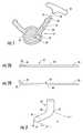
- FIGS. 2A , 2 Bare side elevation views of a K-wire or guide wire showing two configurations of one end portion of the K-wire or guide wire;
- FIG. 3is an enlarged fragmentary view of a K-wire or guide wire showing an end portion shown configured to present an expanded forward face;
- FIG. 4is a fragmentary side sectional view of a jamshidi needle with a K-wire or guide wire in a through bore;
- FIGS. 5A and 5Bare enlarged fragmentary side views of an end portion of a K-wire or guide wire with one embodiment of reformable end portion;
- FIGS. 6A and 6Bare enlarged side views of an end portion, expanded and unexpanded, of a further embodiment of a K-wire or guide wire of the present invention.
- FIG. 7is an enlarged side view of an end portion of a still further embodiment of a K-wire or guide wire of the present invention.
- FIG. 8is an enlarged side view of an end portion of a still further embodiment of a K-wire or guide wire of an end portion of the present invention.
- FIG. 9is an enlarged side view of an end portion of an embodiment of the invention similar to that shown in FIG. 2B ;
- FIG. 10is an enlarged side view of an end portion of a still further embodiment of the present invention.
- FIG. 11is an enlarged side view of the embodiment illustrated in FIG. 10 with the end portions spread apart;
- FIG. 12is an enlarged side view of a still further embodiment of the present invention.
- FIG. 13is an enlarged side view of a still further embodiment of the present invention.
- FIG. 14is a view of the present invention used in a surgical procedure.
- the reference numeral 10designates generally a K-wire or guide wire usable in surgical procedures in combination with a surgical tool such as a Jamshidi needle 12 , drill or tap (not shown), or a surgical device such as a screw, plate or implant.
- K-wiresalso called Kirschner wires
- Jamshidi needlesare also well known in the art and have a shank 14 with a through bore 16 (as would a drill, tap or screw) and a sharpened distal end 17 .
- a handle 18may also be provided at the proximal end 20 of the shank 14 for facilitating insertion of the shank into a surgical site 21 , such as a vertebra 22 with a pedicle 23 in a patient such as a human.
- a surgeonmay manipulate the jamshidi needle 12 using the handle 18 , and may also apply impact force to the shank 14 by striking the handle with a hand or impact tool such as a hammer.
- Jamshidi needlesare used to penetrate bone in the performance of a surgical procedure such as attaching a screw 24 to bone.
- a rod not shown)may be installed in the through bore 16 during hole formation to increase rigidity of the shank 14 . The rod is removed to provide a through bore 16 for the K-wire 10 insertion.
- the K-wire or guide wire 10is inserted into the interior of the bone and the jamshidi needle is removed, leaving the K-wire or guide wire in place.
- the K-wire or guide wireis inserted through one wall of a bone, e.g., a pedicle 23 and is placed against an opposite bone wall. If care is not taken during surgery, the K-wire or guide wire may be pushed through the opposing bone wall creating a risk of injury.
- the present inventionis a solution to this potential problem.
- the K-wire or guide wire 10is typically used as a pilot or guide for other surgical tools or devices such as drills, taps, plates, implants and screws.
- the screwcan have a through bore 44 that receives the K-wire or guide wire for guiding the screw to a drilled and tapped hole 25 .
- the K-wire or guide wire 10is then extracted through the through bore 27 of the screw 24 by simply pulling on the K-wire or guide wire to reduce the frontal area of the K-wire or guide wire substantially to its original size.
- the K-wire or guide wire 10has opposite end portions 26 , 28 and a generally cylindrical intermediate portion 30 positioned between the end portions.
- the length of the K-wire or guide wire 10is preferably long enough to extend beyond both ends of the surgical tool being used, e.g., a jamshidi needle 12 .
- the K-wire or guide wire 10is sized and shaped to be freely movable along the through bore 16 .
- the end portion 28will be referred to as the manipulative end and the end portion will be referred to as the operative end for convenience.
- the entire length of the manipulative end portion 28 and the intermediate portion 30is generally cylindrical to facilitate removal of a tool or device from an installed K-wire or guide wire 10 .
- the operative end portion 26is provided with a section 32 that is controllably deformable.
- the section 32may be an integral portion of the K-wire or guide wire 10 or attached thereto.
- the section 32is configurable to fit within the through bore 16 and freely movable therein. It is insertable into the through bore 16 for insertion into the surgical site 21 for use and for removal from a through bore in the tool or device.
- the K-wire or guide wiremay also be removed prior to a later surgical step if it is no longer needed. For example, if the K-wire or guide wire is not needed to guide the screw 24 for insertion, it may be removed prior to attaching the screw 24 .
- the operative end 26When outside of the through bore 16 , the operative end 26 expands automatically or can be manually expanded to present an expanded face with a projected area greater than the transverse cross sectional area of the K-wire or guide wire 10 while positioned in the through bore 16 .
- the K-wire or guide wire 10 or the deformable portion of the K-wire or guide wiremay be made of a deformable material which will allow at least the operative end 26 to be configured between first and second configurations (see FIGS. 2 A and 2 B) with one configuration ( FIG. 2B ) presenting a larger projected area than the first ( FIG. 2A ) as discussed above.
- a shape memory alloysuch as Nitinol.
- a reversible, solid phase transformation known as martensitic transformationis the force behind shape memory alloys.
- Such alloysare well known and form a crystal structure, which is capable of undergoing a change from one form of crystal structure to another. Temperature change and/or loading can initiate the shape transformation.
- Nitinolis superelastic, able to withstand deformation when a load is applied and return to its original shape when the load is removed. Below its transformation temperature, it displays the shape memory effect. When it is deformed below its transformation temperature, it will remain in that shape until heated above its transformation temperature, at which time it will return to its original shape. The original shape would then be the bent form and then it can be reformed cold to straight. Upon heating, the bend will return. The heat (or temperature increase) can be provided by contact with the patient. Elastically deformable materials may also be used, such as spring steel with high yield strength where stress is induced to change a shape is elastically released to change the shape of the deformed member back to its non stressed shape.
- FIGS. 5A and 5BAn embodiment of the invention is shown in FIGS. 5A and 5B that could be made using a spring material and is described below.
- Plastically deformable materialsmight also be used for some operative end portion 26 configurations.
- the terms resiliently deformable, plastically deformable and springare used generally to indicate a material property when the material is deformed during typical use of the K-wire or guide wire as described herein. Controlled bending can be induced by using controlled weak points such as a groove or the like at selected strategic locations.
- the embodiment in FIGS. 5A and 5Bmight also be used with a plastically deformable material.
- the screw 24 or other tool or device that is anticipated to be the last one used with the K-wire or guide wire 10may be provided with a forcing cone 35 to help reconfigure the end portion 26 back to its unexpanded shape to conform it to fit within a passage like passages 16 , 44 for insertion or removal.
- a forcing cone 35to help reconfigure the end portion 26 back to its unexpanded shape to conform it to fit within a passage like passages 16 , 44 for insertion or removal.
- the operative end 26has a laterally extending portion 36 when out of the through bore 16 .
- the deformation to lateral extensionmay be provided as described above by applying heat to effect bending from memory.
- the portion 36may be provided as a permanent bend in the K-wire or guide wire 10 which can then be deformed to straight by confinement in the through bore 16 , and upon exit from the through bore will reassume its bent configuration.
- the material properties of the end portion 26may be selected to provide for straightening of the bend for removal through a passage or bore which may be facilitated, e.g., by the use of a forcing cone 35 .
- the lateral extensionpresents a larger projected area to further limit forward axial motion into the surgical site.
- FIG. 4shows a surgical tool configuration that can be used to facilitate directing a K-wire or guide wire 10 out of the through bore 16 . It uses a curved tip 37 to direct the exiting K-wire or guide wire 10 .
- the operative end 26is in the form of an expandable cage 40 having a plurality of rods 42 that can assume an extended position;
- FIG. 5Aillustrates a contracted configuration of cage 40 when in a through bore 16 of shank 14 .
- FIG. 5Billustrates the cage 40 in its expanded configuration and a screw positioned on the K-wire or guide wire 10 .
- the embodiment of FIGS. 5A and 5Bmay be constructed in at least two ways, resiliently deformable rods 42 or plastically deformable rods 42 .
- a memory metal alloymay be used.
- a polymeric materialsuch as PEEK may also be used for at least the rods 42 .
- the rods 42are elastically deformable, they can be formed as biased to an outward or expanded configuration, where once outside of the through bore 16 they will move outwardly to relieve induced stress to provide the expanded configuration like in FIG. 5B .
- the rods 42may also be plastically deformable, and upon application of axial force will move to an expanded position as in FIG. 5B .
- the rods 42assume or are in the collapsed configuration and when the rods 42 are outside of the bore, they assume or are forced into the expanded position providing an increased projected area for engagement with material in the surgical site as discussed above.
- the rodsmay also be made of a memory alloy as described above.
- the forcing cone 35may be used to facilitate removal of the K-wire or guide wire 10 through the through bore 44 .
- the distal ends of the rods 42may be held in place with an end cap 43 .
- the projected area of the end portion 26 when expanded as seen in FIG. 5Bwould be that area defined or bounded by outermost extending portions of the rods 42 as at portions 46 .
- FIGS. 6A and 6Billustrate another embodiment of the invention.
- FIG. 6Ashows an end portion 26 with an expandable end bulb 50 that may be made out of a memory alloy, that upon heating assumes the expanded configuration illustrated in FIG. 6B .
- This embodimentis particularly adapted for use when extraction of the K-wire or guide wire is other than through a tool or device passage.
- FIG. 7illustrates another embodiment of the invention. It utilizes a pair of opposed legs 61 , 62 .
- the legs 61 , 62are constructed to move in an outward direction either from spring action or from otherwise reassuming a formed shape as from a temperature change as by using a memory alloy as described above.
- the legs 61 , 62have overlying portions at 63 .
- FIG. 8illustrates an additional embodiment of the invention and is similar to the form shown in FIG. 7 by having two legs 71 , 72 , but the legs do not overlap; but rather the legs diverge from a common area 73 and have a gap 74 therebetween when in the extended position as shown.
- FIGS. 6-8all utilize a shank 14 of one material and an end portion of another material such as a spring material or a memory alloy.
- FIG. 9illustrates a still further embodiment of the present invention. It is similar to the K-wire or guide wire 10 shown in FIG. 2 and has a shank 14 with an attached end portion 26 having a single extending leg 80 shown in its extended configuration.
- the portion 80may be provided as a permanent bend in the K-wire or guide wire 10 which can then be deformed to straight by confinement in the through bore 16 , and upon exit from the passage will reassume its bent configuration.
- the material properties of the end portion 80may be selected to provide for straightening of the bend for removal through a passage which may be facilitated, e.g., by the use of a forcing cone.
- the lateral extensionpresents a larger projected area to further limit forward axial motion into the surgical site.
- FIGS. 10 and 11illustrate a still further embodiment of the present invention.
- the end portion 26 of the K-wire or guide wireincludes a plurality of deformable ends 82 and 84 .
- the K-wire or guide wire of FIGS. 10 and 11can be made from a shape memory alloy such as Nitinol. Other shape memory alloys and materials can also be used.
- the ends 82 and 84are normally deformed outwardly from the longitudinal axis of the K-wire or guide wire at point 87 as shown in FIG. 11 . The deflection of the ends 82 and 84 presents a larger end surface area when the K-wire or guide wire is penetrating a bone.
- This larger end surfaceoffers more resistance and consequently prevents the K-wire or guide wire from penetrating too far into the bone and perhaps passing into an adjacent bone or outside of the intended bone.
- the length of the ends 82 and 84 together with the different shape memory alloysdetermine how quickly the ends 82 and 84 deform outwardly after they enter a bone. The more rapidly they deform, the less they penetrate into a bone.
- the ends 82 and 84collapse together, as shown in FIG. 10 , when the K-wire or guide wire is withdrawn back through the Jamshidi needle.
- a groove 86 on end 82permits projection 88 to fit therein when in the collapsed position.
- FIGS. 12 and 13illustrate other embodiments of the present invention. These embodiments are variations of the embodiment illustrated in FIGS. 10 and 11 .
- the end 82 of the K-wire or guide wirebends outwardly at 90 .
- end 84bends outwardly at 92 .
- This embodimentpermits the ends 82 and 84 to bend outwardly from the longitudinal axis more rapidly than the embodiments of FIGS. 10 and 11 .
- the end 82bends outwardly at 94 and the end 84 bends outwardly at 96 . Bends 94 and 96 are closer to the end portions of 82 and 84 .
- the present inventionalso includes a method of conducting a medical procedure using a K-wire or guide wire, as illustrated in FIG. 14 .
- a surgeon or other medical personnelplaces a surgical tool end at the surgical site.
- the initial surgical tool usedpreferably has a guiding through bore opening at the distal tool end such as that described above for a jamshidi needle 12 .
- a K-wire or guide wire 10is guided to the site by passing the K-wire or guide wire through the through bore 16 until the operative end 26 extends beyond the open end of the through bore 16 .
- a funnel 98helps the surgeon place the K-wire or guide wire into the Jamshidi needle.
- the operative end 26 of the J-wirehas at least a portion deformed after its exit from the through bore 16 such that the deformed portion presents a projected area greater than the cross sectional area of the K-wire or guide wire when in the through bore 16 as described above.
- the deformationcan occur automatically as by increasing the temperature of the operative end portion 26 when it includes a memory metal alloy.
- the deformationmay also be induced by relieving stress induced into the operative end portion as when the deformable portion is constructed of a spring material.
- the deformationmay also be induced mechanically by the application of an axially directed force along the K-wire or guide wire 10 . After at least a portion of the surgery, the K-wire or guide wire can be removed as described above.
- the K-wire or guide wireis used to guide surgical tools and/or devices to the surgical site during the surgical procedure.
- the jamshidi needlecan be withdrawn and a cannulated tap or other instrument can be slid down the K-wire or guide wire and inserted into the bone.
- the tapreaches the expanded ends 82 , 84 of the K-wire it will stop its forward progress.
- this inventionavoids the need for fluoroscopy to determine the position of the tap or other instrument in a bone.
Landscapes
- Health & Medical Sciences (AREA)
- Life Sciences & Earth Sciences (AREA)
- Surgery (AREA)
- Engineering & Computer Science (AREA)
- Orthopedic Medicine & Surgery (AREA)
- Veterinary Medicine (AREA)
- Heart & Thoracic Surgery (AREA)
- Animal Behavior & Ethology (AREA)
- General Health & Medical Sciences (AREA)
- Public Health (AREA)
- Biomedical Technology (AREA)
- Nuclear Medicine, Radiotherapy & Molecular Imaging (AREA)
- Molecular Biology (AREA)
- Medical Informatics (AREA)
- Otolaryngology (AREA)
- Plasma & Fusion (AREA)
- Physics & Mathematics (AREA)
- Pulmonology (AREA)
- Anesthesiology (AREA)
- Hematology (AREA)
- Pathology (AREA)
- Biophysics (AREA)
- Dentistry (AREA)
- Oral & Maxillofacial Surgery (AREA)
- Surgical Instruments (AREA)
- Media Introduction/Drainage Providing Device (AREA)
Abstract
Description
Claims (16)
Priority Applications (12)
| Application Number | Priority Date | Filing Date | Title |
|---|---|---|---|
| US12/823,791US8361102B2 (en) | 2009-06-26 | 2010-06-25 | K-wire and method for surgical procedures |
| US13/037,947US8545531B2 (en) | 2009-06-26 | 2011-03-01 | Guidewire and method for surgical procedures |
| US13/722,641US8540747B2 (en) | 2009-06-26 | 2012-12-20 | K-wire and method for surgical procedures |
| US13/722,667US8540676B2 (en) | 2009-06-26 | 2012-12-20 | Guidewire and method for surgical procedures |
| US13/973,677US8728111B2 (en) | 2009-06-26 | 2013-08-22 | Guidewire and method for surgical procedures |
| US13/974,747US8715311B2 (en) | 2009-06-26 | 2013-08-23 | K-wire and method for surgical procedures |
| US14/269,984US8979889B2 (en) | 2009-06-26 | 2014-05-05 | K-wire and method for surgical procedures |
| US14/280,277US8974485B2 (en) | 2009-06-26 | 2014-05-16 | Guidewire and method for surgical procedures |
| US15/454,674USRE46855E1 (en) | 2009-06-26 | 2017-03-09 | K-wire and method for surgical procedures |
| US15/454,638USRE46872E1 (en) | 2009-06-26 | 2017-03-09 | Guidewire and method for surgical procedures |
| US15/938,638USRE47682E1 (en) | 2009-06-26 | 2018-03-28 | Guidewire and method for surgical procedures |
| US15/938,565USRE47683E1 (en) | 2009-06-26 | 2018-03-28 | K-wire and method for surgical procedures |
Applications Claiming Priority (2)
| Application Number | Priority Date | Filing Date | Title |
|---|---|---|---|
| US22082809P | 2009-06-26 | 2009-06-26 | |
| US12/823,791US8361102B2 (en) | 2009-06-26 | 2010-06-25 | K-wire and method for surgical procedures |
Related Parent Applications (1)
| Application Number | Title | Priority Date | Filing Date |
|---|---|---|---|
| US22082809PContinuation | 2009-06-26 | 2009-06-26 |
Related Child Applications (3)
| Application Number | Title | Priority Date | Filing Date |
|---|---|---|---|
| US13/037,947Continuation-In-PartUS8545531B2 (en) | 2009-06-26 | 2011-03-01 | Guidewire and method for surgical procedures |
| US13/722,641Continuation-In-PartUS8540747B2 (en) | 2009-06-26 | 2012-12-20 | K-wire and method for surgical procedures |
| US13/722,641ContinuationUS8540747B2 (en) | 2009-06-26 | 2012-12-20 | K-wire and method for surgical procedures |
Publications (2)
| Publication Number | Publication Date |
|---|---|
| US20100331893A1 US20100331893A1 (en) | 2010-12-30 |
| US8361102B2true US8361102B2 (en) | 2013-01-29 |
Family
ID=42979808
Family Applications (6)
| Application Number | Title | Priority Date | Filing Date |
|---|---|---|---|
| US12/823,791Expired - Fee RelatedUS8361102B2 (en) | 2009-06-26 | 2010-06-25 | K-wire and method for surgical procedures |
| US13/722,641ActiveUS8540747B2 (en) | 2009-06-26 | 2012-12-20 | K-wire and method for surgical procedures |
| US13/974,747ActiveUS8715311B2 (en) | 2009-06-26 | 2013-08-23 | K-wire and method for surgical procedures |
| US14/269,984CeasedUS8979889B2 (en) | 2009-06-26 | 2014-05-05 | K-wire and method for surgical procedures |
| US15/454,674ActiveUSRE46855E1 (en) | 2009-06-26 | 2017-03-09 | K-wire and method for surgical procedures |
| US15/938,565ActiveUSRE47683E1 (en) | 2009-06-26 | 2018-03-28 | K-wire and method for surgical procedures |
Family Applications After (5)
| Application Number | Title | Priority Date | Filing Date |
|---|---|---|---|
| US13/722,641ActiveUS8540747B2 (en) | 2009-06-26 | 2012-12-20 | K-wire and method for surgical procedures |
| US13/974,747ActiveUS8715311B2 (en) | 2009-06-26 | 2013-08-23 | K-wire and method for surgical procedures |
| US14/269,984CeasedUS8979889B2 (en) | 2009-06-26 | 2014-05-05 | K-wire and method for surgical procedures |
| US15/454,674ActiveUSRE46855E1 (en) | 2009-06-26 | 2017-03-09 | K-wire and method for surgical procedures |
| US15/938,565ActiveUSRE47683E1 (en) | 2009-06-26 | 2018-03-28 | K-wire and method for surgical procedures |
Country Status (13)
| Country | Link |
|---|---|
| US (6) | US8361102B2 (en) |
| EP (2) | EP2445431A2 (en) |
| JP (1) | JP5797646B2 (en) |
| KR (1) | KR20120103543A (en) |
| CN (1) | CN102481162B (en) |
| AU (1) | AU2010265936B2 (en) |
| CA (1) | CA2766292A1 (en) |
| IL (1) | IL217110A0 (en) |
| IN (1) | IN2012DN00371A (en) |
| MX (1) | MX2012000179A (en) |
| NZ (1) | NZ597274A (en) |
| SG (1) | SG177307A1 (en) |
| WO (1) | WO2010151795A2 (en) |
Cited By (4)
| Publication number | Priority date | Publication date | Assignee | Title |
|---|---|---|---|---|
| US20140094861A1 (en)* | 2012-10-01 | 2014-04-03 | Smith & Nephew, Inc. | Surgical locator |
| USRE46855E1 (en) | 2009-06-26 | 2018-05-22 | Orthovita, Inc. | K-wire and method for surgical procedures |
| USRE46872E1 (en) | 2009-06-26 | 2018-05-29 | Orthovita, Inc. | Guidewire and method for surgical procedures |
| US11504172B2 (en) | 2018-11-01 | 2022-11-22 | Arthrex, Inc. | Variable stiffness hammertoe K-wire and methods for use |
Families Citing this family (47)
| Publication number | Priority date | Publication date | Assignee | Title |
|---|---|---|---|---|
| US9949843B2 (en) | 2004-08-09 | 2018-04-24 | Si-Bone Inc. | Apparatus, systems, and methods for the fixation or fusion of bone |
| US8414648B2 (en) | 2004-08-09 | 2013-04-09 | Si-Bone Inc. | Apparatus, systems, and methods for achieving trans-iliac lumbar fusion |
| US8470004B2 (en) | 2004-08-09 | 2013-06-25 | Si-Bone Inc. | Apparatus, systems, and methods for stabilizing a spondylolisthesis |
| US8388667B2 (en) | 2004-08-09 | 2013-03-05 | Si-Bone, Inc. | Systems and methods for the fixation or fusion of bone using compressive implants |
| US20180228621A1 (en) | 2004-08-09 | 2018-08-16 | Mark A. Reiley | Apparatus, systems, and methods for the fixation or fusion of bone |
| US8425570B2 (en) | 2004-08-09 | 2013-04-23 | Si-Bone Inc. | Apparatus, systems, and methods for achieving anterior lumbar interbody fusion |
| US8444693B2 (en) | 2004-08-09 | 2013-05-21 | Si-Bone Inc. | Apparatus, systems, and methods for achieving lumbar facet fusion |
| US9724140B2 (en) | 2010-06-02 | 2017-08-08 | Wright Medical Technology, Inc. | Tapered, cylindrical cruciform hammer toe implant and method |
| US9498273B2 (en) | 2010-06-02 | 2016-11-22 | Wright Medical Technology, Inc. | Orthopedic implant kit |
| US8608785B2 (en) | 2010-06-02 | 2013-12-17 | Wright Medical Technology, Inc. | Hammer toe implant with expansion portion for retrograde approach |
| DE102011001264A1 (en) | 2011-03-14 | 2012-09-20 | Aesculap Ag | Surgical K-wire and surgical screw system |
| US9463052B2 (en) | 2012-01-12 | 2016-10-11 | Integrity Implants Inc. | Access assembly for anterior and lateral spinal procedures |
| US10363140B2 (en) | 2012-03-09 | 2019-07-30 | Si-Bone Inc. | Systems, device, and methods for joint fusion |
| US9044321B2 (en) | 2012-03-09 | 2015-06-02 | Si-Bone Inc. | Integrated implant |
| US8778026B2 (en) | 2012-03-09 | 2014-07-15 | Si-Bone Inc. | Artificial SI joint |
| WO2013134775A1 (en)* | 2012-03-09 | 2013-09-12 | Si-Bone Inc. | Guide pin |
| EP3818947B1 (en) | 2012-05-04 | 2023-08-30 | SI-Bone, Inc. | Fenestrated implant |
| US8945232B2 (en) | 2012-12-31 | 2015-02-03 | Wright Medical Technology, Inc. | Ball and socket implants for correction of hammer toes and claw toes |
| WO2014145902A1 (en) | 2013-03-15 | 2014-09-18 | Si-Bone Inc. | Implants for spinal fixation or fusion |
| CN103239285B (en)* | 2013-05-13 | 2015-01-07 | 张平 | Combined tool for percutaneous screw setting for minimally invasive pelvic fracture |
| US9724139B2 (en) | 2013-10-01 | 2017-08-08 | Wright Medical Technology, Inc. | Hammer toe implant and method |
| US11147688B2 (en) | 2013-10-15 | 2021-10-19 | Si-Bone Inc. | Implant placement |
| US9839448B2 (en) | 2013-10-15 | 2017-12-12 | Si-Bone Inc. | Implant placement |
| US9474561B2 (en) | 2013-11-19 | 2016-10-25 | Wright Medical Technology, Inc. | Two-wire technique for installing hammertoe implant |
| US9545274B2 (en)* | 2014-02-12 | 2017-01-17 | Wright Medical Technology, Inc. | Intramedullary implant, system, and method for inserting an implant into a bone |
| US9498266B2 (en) | 2014-02-12 | 2016-11-22 | Wright Medical Technology, Inc. | Intramedullary implant, system, and method for inserting an implant into a bone |
| US10166033B2 (en) | 2014-09-18 | 2019-01-01 | Si-Bone Inc. | Implants for bone fixation or fusion |
| AU2014331633B2 (en) | 2014-09-18 | 2017-06-22 | Wright Medical Technology, Inc | Hammertoe implant and instrument |
| JP6542362B2 (en) | 2014-09-18 | 2019-07-10 | エスアイ−ボーン・インコーポレイテッドSi−Bone, Inc. | Matrix implant |
| FR3028407B1 (en)* | 2014-11-14 | 2020-10-02 | Clariance | SECURE GUIDANCE DEVICE |
| CN105960211B (en) | 2014-12-19 | 2019-01-11 | 瑞特医疗技术公司 | Intramedullary Anchors for Interphalangeal Arthrodesis |
| US10376206B2 (en) | 2015-04-01 | 2019-08-13 | Si-Bone Inc. | Neuromonitoring systems and methods for bone fixation or fusion procedures |
| US10058350B2 (en) | 2015-09-24 | 2018-08-28 | Integrity Implants, Inc. | Access assembly for anterior and lateral spinal procedures |
| US11116519B2 (en) | 2017-09-26 | 2021-09-14 | Si-Bone Inc. | Systems and methods for decorticating the sacroiliac joint |
| CN110279931B (en)* | 2018-03-15 | 2021-12-28 | 王恩长 | Multifunctional balloon catheter and system |
| ES3011907T3 (en) | 2018-03-28 | 2025-04-08 | Si Bone Inc | Threaded implants for use across bone segments |
| JP7440024B2 (en)* | 2018-06-15 | 2024-02-28 | ネオ・メディカル・ソシエテ・アノニム | pedicle marker |
| US11369419B2 (en) | 2019-02-14 | 2022-06-28 | Si-Bone Inc. | Implants for spinal fixation and or fusion |
| EP4613244A2 (en) | 2019-02-14 | 2025-09-10 | SI-Bone Inc. | Implants for spinal fixation and or fusion |
| WO2020172280A1 (en) | 2019-02-21 | 2020-08-27 | Glw, Inc. | Hybrid bone fixation wire |
| JP7646654B2 (en) | 2019-11-21 | 2025-03-17 | エスアイ-ボーン・インコーポレイテッド | Rod coupling assembly for bone stabilization construct - Patent application |
| AU2020392121B2 (en) | 2019-11-27 | 2025-05-22 | Si-Bone, Inc. | Bone stabilizing implants and methods of placement across SI joints |
| EP4072452A4 (en) | 2019-12-09 | 2023-12-20 | SI-Bone, Inc. | Sacro-iliac joint stabilizing implants and methods of implantation |
| EP4259015A4 (en) | 2020-12-09 | 2024-09-11 | SI-Bone, Inc. | SACROILIAC JOINT STABILIZATION IMPLANTS AND METHODS OF IMPLANTATION |
| EP4319658A1 (en) | 2021-04-06 | 2024-02-14 | GLW, Inc. | Bone fixation devices, systems, kits, and methods |
| WO2025038769A1 (en) | 2023-08-15 | 2025-02-20 | Si-Bone Inc. | Pelvic stabilization implants, methods of use and manufacture |
| WO2025169259A1 (en)* | 2024-02-05 | 2025-08-14 | 株式会社スパインクロニクルジャパン | Therapeutic instrument |
Citations (18)
| Publication number | Priority date | Publication date | Assignee | Title |
|---|---|---|---|---|
| US4654028A (en) | 1985-03-14 | 1987-03-31 | Hisayoshi Suma | Incision opening expansion holder for inosculation |
| US5217484A (en) | 1991-06-07 | 1993-06-08 | Marks Michael P | Retractable-wire catheter device and method |
| US5431651A (en) | 1993-02-08 | 1995-07-11 | Goble; E. Marlowe | Cross pin and set screw femoral and tibial fixation method |
| US5433723A (en) | 1991-10-11 | 1995-07-18 | Angiomed Ag | Apparatus for widening a stenosis |
| US5509919A (en) | 1993-09-24 | 1996-04-23 | Young; Merry A. | Apparatus for guiding a reaming instrument |
| US5653716A (en) | 1994-12-29 | 1997-08-05 | Acufex Microsurgical, Inc. | Suture manipulating instrument with grasping members |
| US5795308A (en) | 1995-03-09 | 1998-08-18 | Russin; Lincoln D. | Apparatus for coaxial breast biopsy |
| US20050267555A1 (en) | 2004-05-28 | 2005-12-01 | Marnfeldt Goran N | Engagement tool for implantable medical devices |
| US20060064101A1 (en) | 2004-02-12 | 2006-03-23 | Arthrocare Corporation | Bone access system |
| US7169160B1 (en) | 1998-07-28 | 2007-01-30 | Medtronic, Inc. | Device for anchoring tubular element |
| US20070191778A1 (en)* | 2005-12-02 | 2007-08-16 | Cook Incorporated | Wire guide with engaging portion |
| US20070239159A1 (en) | 2005-07-22 | 2007-10-11 | Vertiflex, Inc. | Systems and methods for stabilization of bone structures |
| US20070270896A1 (en) | 2006-04-21 | 2007-11-22 | Mi4Spine, Llc | Pedicle access device |
| US20080071223A1 (en) | 2006-09-15 | 2008-03-20 | Inventit, Llc | Steerable surgical guide wire introducer |
| US7367975B2 (en) | 2004-06-21 | 2008-05-06 | Cierra, Inc. | Energy based devices and methods for treatment of anatomic tissue defects |
| US20090182245A1 (en) | 2008-01-16 | 2009-07-16 | Roberto Zambelli | Guide device for localising a neoplasia to be removed during a surgical procedure |
| US7575578B2 (en) | 2002-02-13 | 2009-08-18 | Karl Storz Gmbh & Co. Kg | Surgical drill guide |
| US20090275946A1 (en) | 2008-05-05 | 2009-11-05 | Duncan Scott F M | Intramedullary Fixation Device for Small Bone Fractures |
Family Cites Families (32)
| Publication number | Priority date | Publication date | Assignee | Title |
|---|---|---|---|---|
| US4909789A (en) | 1986-03-28 | 1990-03-20 | Olympus Optical Co., Ltd. | Observation assisting forceps |
| US5026379A (en) | 1989-12-05 | 1991-06-25 | Inbae Yoon | Multi-functional instruments and stretchable ligating and occluding devices |
| US5353784A (en) | 1993-04-02 | 1994-10-11 | The Research Foundation Of Suny | Endoscopic device and method of use |
| US5512037A (en) | 1994-05-12 | 1996-04-30 | United States Surgical Corporation | Percutaneous surgical retractor |
| US5431657A (en) | 1994-05-23 | 1995-07-11 | Zimmer, Inc. | Instrument for installing an acetabular cup assembly |
| DE4424394B4 (en) | 1994-07-13 | 2004-12-16 | Bip Acquisition Company Inc., Wilmington | Device for marking tissue sites |
| US5607446A (en) | 1995-01-31 | 1997-03-04 | Beehler; Cecil C. | Pupil dilator |
| JPH1057398A (en)* | 1996-08-15 | 1998-03-03 | Mitsuru Monma | Turn preventive device for operation of femur and humerus fracture |
| GB2327614B (en) | 1997-07-30 | 2002-03-06 | Univ Dundee | A hypodermic needle |
| US7517348B2 (en) | 1998-09-03 | 2009-04-14 | Rubicor Medical, Inc. | Devices and methods for performing procedures on a breast |
| ES2228165T3 (en) | 1998-12-09 | 2005-04-01 | Cook Incorporated | HOLLOW NEEDLE, CURVED, SUPERELASTIC, FOR MEDICAL USE. |
| US20020188275A1 (en) | 1998-12-09 | 2002-12-12 | Mcguckin James F. | Multi Directional infusion needle |
| US6482178B1 (en)* | 1999-05-21 | 2002-11-19 | Cook Urological Incorporated | Localization device with anchoring barbs |
| SE514718C2 (en) | 1999-06-29 | 2001-04-09 | Jan Otto Solem | Apparatus for treating defective closure of the mitral valve apparatus |
| US6478776B1 (en) | 2000-04-05 | 2002-11-12 | Biocardia, Inc. | Implant delivery catheter system and methods for its use |
| US6679886B2 (en)* | 2000-09-01 | 2004-01-20 | Synthes (Usa) | Tools and methods for creating cavities in bone |
| US6723038B1 (en) | 2000-10-06 | 2004-04-20 | Myocor, Inc. | Methods and devices for improving mitral valve function |
| CN2460058Y (en)* | 2001-01-13 | 2001-11-21 | 王嵩峰 | Simple locator for fracture of neck of femur |
| US7087040B2 (en) | 2001-02-28 | 2006-08-08 | Rex Medical, L.P. | Apparatus for delivering ablation fluid to treat lesions |
| CN2533858Y (en)* | 2002-02-04 | 2003-02-05 | 保定市第二医院 | Intracranial hematoncus drainage apparatus |
| US6997903B2 (en) | 2003-02-10 | 2006-02-14 | Bandula Wijay | Local drug delivery catheter |
| US7056286B2 (en) | 2003-11-12 | 2006-06-06 | Adrian Ravenscroft | Medical device anchor and delivery system |
| EP1838229B1 (en)* | 2005-01-20 | 2009-08-26 | Wilson-Cook Medical Inc. | Biopsy forceps |
| WO2007008794A2 (en)* | 2005-07-07 | 2007-01-18 | Crosstrees Medical, Inc. | Devices and methods for the treatment of bone fracture |
| US20070213584A1 (en)* | 2006-03-10 | 2007-09-13 | Kim Daniel H | Percutaneous access and visualization of the spine |
| US8702720B2 (en) | 2006-05-03 | 2014-04-22 | Cook Medical Technologies Llc | Tassel tip wire guide |
| US8142416B2 (en) | 2006-09-15 | 2012-03-27 | Marshall Ephraim Stauber | Steerable surgical guide wire introducer |
| US20100057141A1 (en) | 2008-08-27 | 2010-03-04 | Custom Spine, Inc. | Multi-anchor anti-back out mechanism and method |
| US20100268029A1 (en) | 2009-04-21 | 2010-10-21 | Xlumena, Inc. | Methods and apparatus for advancing a device from one body lumen to another |
| US8545531B2 (en) | 2009-06-26 | 2013-10-01 | Safe Wire Holding, Llc | Guidewire and method for surgical procedures |
| IN2012DN00371A (en) | 2009-06-26 | 2015-08-21 | Safe Wire Holding Llc | |
| US8814775B2 (en) | 2010-03-18 | 2014-08-26 | Cianna Medical, Inc. | Expandable brachytherapy apparatus and methods for using them |
- 2010
- 2010-06-25ININ371DEN2012patent/IN2012DN00371A/enunknown
- 2010-06-25WOPCT/US2010/040032patent/WO2010151795A2/enactiveApplication Filing
- 2010-06-25JPJP2012517781Apatent/JP5797646B2/ennot_activeExpired - Fee Related
- 2010-06-25CNCN201080036809.XApatent/CN102481162B/ennot_activeExpired - Fee Related
- 2010-06-25AUAU2010265936Apatent/AU2010265936B2/ennot_activeCeased
- 2010-06-25USUS12/823,791patent/US8361102B2/ennot_activeExpired - Fee Related
- 2010-06-25EPEP10731658Apatent/EP2445431A2/ennot_activeWithdrawn
- 2010-06-25EPEP15198750.0Apatent/EP3020350A1/ennot_activeWithdrawn
- 2010-06-25SGSG2011094869Apatent/SG177307A1/enunknown
- 2010-06-25MXMX2012000179Apatent/MX2012000179A/ennot_activeApplication Discontinuation
- 2010-06-25NZNZ597274Apatent/NZ597274A/ennot_activeIP Right Cessation
- 2010-06-25CACA2766292Apatent/CA2766292A1/ennot_activeAbandoned
- 2010-06-25KRKR1020127001992Apatent/KR20120103543A/ennot_activeCeased
- 2011
- 2011-12-21ILIL217110Apatent/IL217110A0/enunknown
- 2012
- 2012-12-20USUS13/722,641patent/US8540747B2/enactiveActive
- 2013
- 2013-08-23USUS13/974,747patent/US8715311B2/enactiveActive
- 2014
- 2014-05-05USUS14/269,984patent/US8979889B2/ennot_activeCeased
- 2017
- 2017-03-09USUS15/454,674patent/USRE46855E1/enactiveActive
- 2018
- 2018-03-28USUS15/938,565patent/USRE47683E1/enactiveActive
Patent Citations (19)
| Publication number | Priority date | Publication date | Assignee | Title |
|---|---|---|---|---|
| US4654028A (en) | 1985-03-14 | 1987-03-31 | Hisayoshi Suma | Incision opening expansion holder for inosculation |
| US5217484A (en) | 1991-06-07 | 1993-06-08 | Marks Michael P | Retractable-wire catheter device and method |
| US5433723A (en) | 1991-10-11 | 1995-07-18 | Angiomed Ag | Apparatus for widening a stenosis |
| US5431651A (en) | 1993-02-08 | 1995-07-11 | Goble; E. Marlowe | Cross pin and set screw femoral and tibial fixation method |
| US5509919A (en) | 1993-09-24 | 1996-04-23 | Young; Merry A. | Apparatus for guiding a reaming instrument |
| US5653716A (en) | 1994-12-29 | 1997-08-05 | Acufex Microsurgical, Inc. | Suture manipulating instrument with grasping members |
| US5795308A (en) | 1995-03-09 | 1998-08-18 | Russin; Lincoln D. | Apparatus for coaxial breast biopsy |
| US7169160B1 (en) | 1998-07-28 | 2007-01-30 | Medtronic, Inc. | Device for anchoring tubular element |
| US7575578B2 (en) | 2002-02-13 | 2009-08-18 | Karl Storz Gmbh & Co. Kg | Surgical drill guide |
| US20060064101A1 (en) | 2004-02-12 | 2006-03-23 | Arthrocare Corporation | Bone access system |
| US20050267555A1 (en) | 2004-05-28 | 2005-12-01 | Marnfeldt Goran N | Engagement tool for implantable medical devices |
| US7367975B2 (en) | 2004-06-21 | 2008-05-06 | Cierra, Inc. | Energy based devices and methods for treatment of anatomic tissue defects |
| US20070239159A1 (en) | 2005-07-22 | 2007-10-11 | Vertiflex, Inc. | Systems and methods for stabilization of bone structures |
| US20070191778A1 (en)* | 2005-12-02 | 2007-08-16 | Cook Incorporated | Wire guide with engaging portion |
| US7914493B2 (en) | 2005-12-02 | 2011-03-29 | Cook Medical Technologies Llc | Wire guide with engaging portion |
| US20070270896A1 (en) | 2006-04-21 | 2007-11-22 | Mi4Spine, Llc | Pedicle access device |
| US20080071223A1 (en) | 2006-09-15 | 2008-03-20 | Inventit, Llc | Steerable surgical guide wire introducer |
| US20090182245A1 (en) | 2008-01-16 | 2009-07-16 | Roberto Zambelli | Guide device for localising a neoplasia to be removed during a surgical procedure |
| US20090275946A1 (en) | 2008-05-05 | 2009-11-05 | Duncan Scott F M | Intramedullary Fixation Device for Small Bone Fractures |
Cited By (7)
| Publication number | Priority date | Publication date | Assignee | Title |
|---|---|---|---|---|
| USRE46855E1 (en) | 2009-06-26 | 2018-05-22 | Orthovita, Inc. | K-wire and method for surgical procedures |
| USRE46872E1 (en) | 2009-06-26 | 2018-05-29 | Orthovita, Inc. | Guidewire and method for surgical procedures |
| USRE47682E1 (en) | 2009-06-26 | 2019-11-05 | Orthovita, Inc. | Guidewire and method for surgical procedures |
| USRE47683E1 (en) | 2009-06-26 | 2019-11-05 | Orthovita, Inc. | K-wire and method for surgical procedures |
| US20140094861A1 (en)* | 2012-10-01 | 2014-04-03 | Smith & Nephew, Inc. | Surgical locator |
| US11504172B2 (en) | 2018-11-01 | 2022-11-22 | Arthrex, Inc. | Variable stiffness hammertoe K-wire and methods for use |
| US12256964B2 (en) | 2018-11-01 | 2025-03-25 | Arthrex, Inc. | Variable stiffness hammertoe k-wire and methods for use |
Also Published As
| Publication number | Publication date |
|---|---|
| IN2012DN00371A (en) | 2015-08-21 |
| CN102481162A (en) | 2012-05-30 |
| EP2445431A2 (en) | 2012-05-02 |
| WO2010151795A2 (en) | 2010-12-29 |
| US20130110118A1 (en) | 2013-05-02 |
| CA2766292A1 (en) | 2010-12-29 |
| US20130345712A1 (en) | 2013-12-26 |
| MX2012000179A (en) | 2012-05-23 |
| US8540747B2 (en) | 2013-09-24 |
| KR20120103543A (en) | 2012-09-19 |
| USRE46855E1 (en) | 2018-05-22 |
| JP5797646B2 (en) | 2015-10-21 |
| IL217110A0 (en) | 2012-03-01 |
| WO2010151795A3 (en) | 2011-03-31 |
| USRE47683E1 (en) | 2019-11-05 |
| AU2010265936A1 (en) | 2012-01-19 |
| US8979889B2 (en) | 2015-03-17 |
| EP3020350A1 (en) | 2016-05-18 |
| AU2010265936B2 (en) | 2015-08-27 |
| CN102481162B (en) | 2015-11-25 |
| SG177307A1 (en) | 2012-02-28 |
| JP2012531275A (en) | 2012-12-10 |
| US20140324057A1 (en) | 2014-10-30 |
| US8715311B2 (en) | 2014-05-06 |
| NZ597274A (en) | 2014-05-30 |
| US20100331893A1 (en) | 2010-12-30 |
Similar Documents
| Publication | Publication Date | Title |
|---|---|---|
| USRE47683E1 (en) | K-wire and method for surgical procedures | |
| USRE47682E1 (en) | Guidewire and method for surgical procedures | |
| US20080255555A1 (en) | Temporary anchorable tether systems and methods | |
| US10463359B2 (en) | Device for anchoring a suture | |
| US10149709B2 (en) | Percutaneous bone screw device | |
| US20130030478A1 (en) | Anchor wire system and method | |
| AU2015261581B2 (en) | K-wire and method for surgical procedures |
Legal Events
| Date | Code | Title | Description |
|---|---|---|---|
| AS | Assignment | Owner name:SAFE WIRE HOLDING, LLC, FLORIDA Free format text:ASSIGNMENT OF ASSIGNORS INTEREST;ASSIGNORS:GEIST, WYATT DRAKE;GEIST, ARDEN ALLEN, SR;REEL/FRAME:024596/0777 Effective date:20100625 | |
| STCF | Information on status: patent grant | Free format text:PATENTED CASE | |
| FEPP | Fee payment procedure | Free format text:PAT HOLDER NO LONGER CLAIMS SMALL ENTITY STATUS, ENTITY STATUS SET TO UNDISCOUNTED (ORIGINAL EVENT CODE: STOL); ENTITY STATUS OF PATENT OWNER: LARGE ENTITY | |
| AS | Assignment | Owner name:ORTHOVITA, INC., PENNSYLVANIA Free format text:ASSIGNMENT OF ASSIGNORS INTEREST;ASSIGNORS:SAFEWIRE, LLC;SAFE WIRE HOLDING, LLC;REEL/FRAME:038636/0487 Effective date:20160408 | |
| FPAY | Fee payment | Year of fee payment:4 | |
| MAFP | Maintenance fee payment | Free format text:PAYMENT OF MAINTENANCE FEE, 8TH YEAR, LARGE ENTITY (ORIGINAL EVENT CODE: M1552); ENTITY STATUS OF PATENT OWNER: LARGE ENTITY Year of fee payment:8 | |
| AS | Assignment | Owner name:HOWMEDICA OSTEONICS CORP., NEW JERSEY Free format text:ASSIGNMENT OF ASSIGNORS INTEREST;ASSIGNOR:ORTHOVITA, INC.;REEL/FRAME:065734/0863 Effective date:20201108 | |
| AS | Assignment | Owner name:HOWMEDICA OSTEONICS CORP., NEW JERSEY Free format text:CORRECTIVE ASSIGNMENT TO CORRECT THE ASSIGNMENT EXECUTION DATE FROM 11/8/2020 TO 11/8/2023 PREVIOUSLY RECORDED ON REEL 065734 FRAME 0863. ASSIGNOR(S) HEREBY CONFIRMS THE ASSIGNMENT;ASSIGNOR:ORTHOVITA, INC.;REEL/FRAME:065819/0377 Effective date:20231108 | |
| FEPP | Fee payment procedure | Free format text:MAINTENANCE FEE REMINDER MAILED (ORIGINAL EVENT CODE: REM.); ENTITY STATUS OF PATENT OWNER: LARGE ENTITY | |
| LAPS | Lapse for failure to pay maintenance fees | Free format text:PATENT EXPIRED FOR FAILURE TO PAY MAINTENANCE FEES (ORIGINAL EVENT CODE: EXP.); ENTITY STATUS OF PATENT OWNER: LARGE ENTITY | |
| STCH | Information on status: patent discontinuation | Free format text:PATENT EXPIRED DUE TO NONPAYMENT OF MAINTENANCE FEES UNDER 37 CFR 1.362 | |
| FP | Lapsed due to failure to pay maintenance fee | Effective date:20250129 |