US8361028B2 - Drug delivery device - Google Patents
Drug delivery deviceDownload PDFInfo
- Publication number
- US8361028B2 US8361028B2US13/184,479US201113184479AUS8361028B2US 8361028 B2US8361028 B2US 8361028B2US 201113184479 AUS201113184479 AUS 201113184479AUS 8361028 B2US8361028 B2US 8361028B2
- Authority
- US
- United States
- Prior art keywords
- ratchet
- drug
- chamber
- gas
- delivery
- Prior art date
- Legal status (The legal status is an assumption and is not a legal conclusion. Google has not performed a legal analysis and makes no representation as to the accuracy of the status listed.)
- Expired - Fee Related
Links
Images


Classifications
- A—HUMAN NECESSITIES
- A61—MEDICAL OR VETERINARY SCIENCE; HYGIENE
- A61M—DEVICES FOR INTRODUCING MEDIA INTO, OR ONTO, THE BODY; DEVICES FOR TRANSDUCING BODY MEDIA OR FOR TAKING MEDIA FROM THE BODY; DEVICES FOR PRODUCING OR ENDING SLEEP OR STUPOR
- A61M5/00—Devices for bringing media into the body in a subcutaneous, intra-vascular or intramuscular way; Accessories therefor, e.g. filling or cleaning devices, arm-rests
- A61M5/14—Infusion devices, e.g. infusing by gravity; Blood infusion; Accessories therefor
- A61M5/142—Pressure infusion, e.g. using pumps
- A61M5/145—Pressure infusion, e.g. using pumps using pressurised reservoirs, e.g. pressurised by means of pistons
- A61M5/155—Pressure infusion, e.g. using pumps using pressurised reservoirs, e.g. pressurised by means of pistons pressurised by gas introduced into the reservoir
- A—HUMAN NECESSITIES
- A61—MEDICAL OR VETERINARY SCIENCE; HYGIENE
- A61M—DEVICES FOR INTRODUCING MEDIA INTO, OR ONTO, THE BODY; DEVICES FOR TRANSDUCING BODY MEDIA OR FOR TAKING MEDIA FROM THE BODY; DEVICES FOR PRODUCING OR ENDING SLEEP OR STUPOR
- A61M5/00—Devices for bringing media into the body in a subcutaneous, intra-vascular or intramuscular way; Accessories therefor, e.g. filling or cleaning devices, arm-rests
- A61M5/14—Infusion devices, e.g. infusing by gravity; Blood infusion; Accessories therefor
- A61M5/142—Pressure infusion, e.g. using pumps
- A61M5/14212—Pumping with an aspiration and an expulsion action
- A61M5/14216—Reciprocating piston type
- A—HUMAN NECESSITIES
- A61—MEDICAL OR VETERINARY SCIENCE; HYGIENE
- A61M—DEVICES FOR INTRODUCING MEDIA INTO, OR ONTO, THE BODY; DEVICES FOR TRANSDUCING BODY MEDIA OR FOR TAKING MEDIA FROM THE BODY; DEVICES FOR PRODUCING OR ENDING SLEEP OR STUPOR
- A61M5/00—Devices for bringing media into the body in a subcutaneous, intra-vascular or intramuscular way; Accessories therefor, e.g. filling or cleaning devices, arm-rests
- A61M5/14—Infusion devices, e.g. infusing by gravity; Blood infusion; Accessories therefor
- A61M5/142—Pressure infusion, e.g. using pumps
- A61M5/14244—Pressure infusion, e.g. using pumps adapted to be carried by the patient, e.g. portable on the body
- A61M5/14248—Pressure infusion, e.g. using pumps adapted to be carried by the patient, e.g. portable on the body of the skin patch type
- A—HUMAN NECESSITIES
- A61—MEDICAL OR VETERINARY SCIENCE; HYGIENE
- A61M—DEVICES FOR INTRODUCING MEDIA INTO, OR ONTO, THE BODY; DEVICES FOR TRANSDUCING BODY MEDIA OR FOR TAKING MEDIA FROM THE BODY; DEVICES FOR PRODUCING OR ENDING SLEEP OR STUPOR
- A61M5/00—Devices for bringing media into the body in a subcutaneous, intra-vascular or intramuscular way; Accessories therefor, e.g. filling or cleaning devices, arm-rests
- A61M5/14—Infusion devices, e.g. infusing by gravity; Blood infusion; Accessories therefor
- A61M5/158—Needles for infusions; Accessories therefor, e.g. for inserting infusion needles, or for holding them on the body
- A—HUMAN NECESSITIES
- A61—MEDICAL OR VETERINARY SCIENCE; HYGIENE
- A61K—PREPARATIONS FOR MEDICAL, DENTAL OR TOILETRY PURPOSES
- A61K33/00—Medicinal preparations containing inorganic active ingredients
- A61K33/22—Boron compounds
- A—HUMAN NECESSITIES
- A61—MEDICAL OR VETERINARY SCIENCE; HYGIENE
- A61M—DEVICES FOR INTRODUCING MEDIA INTO, OR ONTO, THE BODY; DEVICES FOR TRANSDUCING BODY MEDIA OR FOR TAKING MEDIA FROM THE BODY; DEVICES FOR PRODUCING OR ENDING SLEEP OR STUPOR
- A61M5/00—Devices for bringing media into the body in a subcutaneous, intra-vascular or intramuscular way; Accessories therefor, e.g. filling or cleaning devices, arm-rests
- A61M5/14—Infusion devices, e.g. infusing by gravity; Blood infusion; Accessories therefor
- A61M2005/1401—Functional features
- A61M2005/1405—Patient controlled analgesia [PCA]
- A—HUMAN NECESSITIES
- A61—MEDICAL OR VETERINARY SCIENCE; HYGIENE
- A61M—DEVICES FOR INTRODUCING MEDIA INTO, OR ONTO, THE BODY; DEVICES FOR TRANSDUCING BODY MEDIA OR FOR TAKING MEDIA FROM THE BODY; DEVICES FOR PRODUCING OR ENDING SLEEP OR STUPOR
- A61M5/00—Devices for bringing media into the body in a subcutaneous, intra-vascular or intramuscular way; Accessories therefor, e.g. filling or cleaning devices, arm-rests
- A61M5/14—Infusion devices, e.g. infusing by gravity; Blood infusion; Accessories therefor
- A61M5/142—Pressure infusion, e.g. using pumps
- A61M2005/14204—Pressure infusion, e.g. using pumps with gas-producing electrochemical cell
- A—HUMAN NECESSITIES
- A61—MEDICAL OR VETERINARY SCIENCE; HYGIENE
- A61M—DEVICES FOR INTRODUCING MEDIA INTO, OR ONTO, THE BODY; DEVICES FOR TRANSDUCING BODY MEDIA OR FOR TAKING MEDIA FROM THE BODY; DEVICES FOR PRODUCING OR ENDING SLEEP OR STUPOR
- A61M5/00—Devices for bringing media into the body in a subcutaneous, intra-vascular or intramuscular way; Accessories therefor, e.g. filling or cleaning devices, arm-rests
- A61M5/14—Infusion devices, e.g. infusing by gravity; Blood infusion; Accessories therefor
- A61M5/142—Pressure infusion, e.g. using pumps
- A61M5/14244—Pressure infusion, e.g. using pumps adapted to be carried by the patient, e.g. portable on the body
- A61M5/14248—Pressure infusion, e.g. using pumps adapted to be carried by the patient, e.g. portable on the body of the skin patch type
- A61M2005/1426—Pressure infusion, e.g. using pumps adapted to be carried by the patient, e.g. portable on the body of the skin patch type with means for preventing access to the needle after use
- A—HUMAN NECESSITIES
- A61—MEDICAL OR VETERINARY SCIENCE; HYGIENE
- A61M—DEVICES FOR INTRODUCING MEDIA INTO, OR ONTO, THE BODY; DEVICES FOR TRANSDUCING BODY MEDIA OR FOR TAKING MEDIA FROM THE BODY; DEVICES FOR PRODUCING OR ENDING SLEEP OR STUPOR
- A61M5/00—Devices for bringing media into the body in a subcutaneous, intra-vascular or intramuscular way; Accessories therefor, e.g. filling or cleaning devices, arm-rests
- A61M5/14—Infusion devices, e.g. infusing by gravity; Blood infusion; Accessories therefor
- A61M5/142—Pressure infusion, e.g. using pumps
- A61M5/145—Pressure infusion, e.g. using pumps using pressurised reservoirs, e.g. pressurised by means of pistons
- A61M5/1452—Pressure infusion, e.g. using pumps using pressurised reservoirs, e.g. pressurised by means of pistons pressurised by means of pistons
- A61M2005/14533—Pressure infusion, e.g. using pumps using pressurised reservoirs, e.g. pressurised by means of pistons pressurised by means of pistons cam actuated
- A—HUMAN NECESSITIES
- A61—MEDICAL OR VETERINARY SCIENCE; HYGIENE
- A61M—DEVICES FOR INTRODUCING MEDIA INTO, OR ONTO, THE BODY; DEVICES FOR TRANSDUCING BODY MEDIA OR FOR TAKING MEDIA FROM THE BODY; DEVICES FOR PRODUCING OR ENDING SLEEP OR STUPOR
- A61M5/00—Devices for bringing media into the body in a subcutaneous, intra-vascular or intramuscular way; Accessories therefor, e.g. filling or cleaning devices, arm-rests
- A61M5/178—Syringes
- A61M5/31—Details
- A61M5/315—Pistons; Piston-rods; Guiding, blocking or restricting the movement of the rod or piston; Appliances on the rod for facilitating dosing ; Dosing mechanisms
- A61M5/31511—Piston or piston-rod constructions, e.g. connection of piston with piston-rod
- A61M2005/31518—Piston or piston-rod constructions, e.g. connection of piston with piston-rod designed to reduce the overall size of an injection device, e.g. using flexible or pivotally connected chain-like rod members
- A—HUMAN NECESSITIES
- A61—MEDICAL OR VETERINARY SCIENCE; HYGIENE
- A61M—DEVICES FOR INTRODUCING MEDIA INTO, OR ONTO, THE BODY; DEVICES FOR TRANSDUCING BODY MEDIA OR FOR TAKING MEDIA FROM THE BODY; DEVICES FOR PRODUCING OR ENDING SLEEP OR STUPOR
- A61M5/00—Devices for bringing media into the body in a subcutaneous, intra-vascular or intramuscular way; Accessories therefor, e.g. filling or cleaning devices, arm-rests
- A61M5/14—Infusion devices, e.g. infusing by gravity; Blood infusion; Accessories therefor
- A61M5/142—Pressure infusion, e.g. using pumps
- A61M5/145—Pressure infusion, e.g. using pumps using pressurised reservoirs, e.g. pressurised by means of pistons
- A61M5/1452—Pressure infusion, e.g. using pumps using pressurised reservoirs, e.g. pressurised by means of pistons pressurised by means of pistons
- A61M5/1454—Pressure infusion, e.g. using pumps using pressurised reservoirs, e.g. pressurised by means of pistons pressurised by means of pistons spring-actuated, e.g. by a clockwork
- A—HUMAN NECESSITIES
- A61—MEDICAL OR VETERINARY SCIENCE; HYGIENE
- A61M—DEVICES FOR INTRODUCING MEDIA INTO, OR ONTO, THE BODY; DEVICES FOR TRANSDUCING BODY MEDIA OR FOR TAKING MEDIA FROM THE BODY; DEVICES FOR PRODUCING OR ENDING SLEEP OR STUPOR
- A61M5/00—Devices for bringing media into the body in a subcutaneous, intra-vascular or intramuscular way; Accessories therefor, e.g. filling or cleaning devices, arm-rests
- A61M5/178—Syringes
- A61M5/20—Automatic syringes, e.g. with automatically actuated piston rod, with automatic needle injection, filling automatically
- A61M5/2046—Media being expelled from injector by gas generation, e.g. explosive charge
- A—HUMAN NECESSITIES
- A61—MEDICAL OR VETERINARY SCIENCE; HYGIENE
- A61M—DEVICES FOR INTRODUCING MEDIA INTO, OR ONTO, THE BODY; DEVICES FOR TRANSDUCING BODY MEDIA OR FOR TAKING MEDIA FROM THE BODY; DEVICES FOR PRODUCING OR ENDING SLEEP OR STUPOR
- A61M5/00—Devices for bringing media into the body in a subcutaneous, intra-vascular or intramuscular way; Accessories therefor, e.g. filling or cleaning devices, arm-rests
- A61M5/178—Syringes
- A61M5/31—Details
- A61M5/315—Pistons; Piston-rods; Guiding, blocking or restricting the movement of the rod or piston; Appliances on the rod for facilitating dosing ; Dosing mechanisms
- A61M5/31533—Dosing mechanisms, i.e. setting a dose
- A61M5/31545—Setting modes for dosing
- A61M5/31548—Mechanically operated dose setting member
- A61M5/3155—Mechanically operated dose setting member by rotational movement of dose setting member, e.g. during setting or filling of a syringe
- A61M5/31551—Mechanically operated dose setting member by rotational movement of dose setting member, e.g. during setting or filling of a syringe including axial movement of dose setting member
- A—HUMAN NECESSITIES
- A61—MEDICAL OR VETERINARY SCIENCE; HYGIENE
- A61M—DEVICES FOR INTRODUCING MEDIA INTO, OR ONTO, THE BODY; DEVICES FOR TRANSDUCING BODY MEDIA OR FOR TAKING MEDIA FROM THE BODY; DEVICES FOR PRODUCING OR ENDING SLEEP OR STUPOR
- A61M5/00—Devices for bringing media into the body in a subcutaneous, intra-vascular or intramuscular way; Accessories therefor, e.g. filling or cleaning devices, arm-rests
- A61M5/178—Syringes
- A61M5/31—Details
- A61M5/315—Pistons; Piston-rods; Guiding, blocking or restricting the movement of the rod or piston; Appliances on the rod for facilitating dosing ; Dosing mechanisms
- A61M5/31565—Administration mechanisms, i.e. constructional features, modes of administering a dose
- A61M5/31566—Means improving security or handling thereof
- A61M5/31571—Means preventing accidental administration
- A—HUMAN NECESSITIES
- A61—MEDICAL OR VETERINARY SCIENCE; HYGIENE
- A61M—DEVICES FOR INTRODUCING MEDIA INTO, OR ONTO, THE BODY; DEVICES FOR TRANSDUCING BODY MEDIA OR FOR TAKING MEDIA FROM THE BODY; DEVICES FOR PRODUCING OR ENDING SLEEP OR STUPOR
- A61M5/00—Devices for bringing media into the body in a subcutaneous, intra-vascular or intramuscular way; Accessories therefor, e.g. filling or cleaning devices, arm-rests
- A61M5/178—Syringes
- A61M5/31—Details
- A61M5/315—Pistons; Piston-rods; Guiding, blocking or restricting the movement of the rod or piston; Appliances on the rod for facilitating dosing ; Dosing mechanisms
- A61M5/31565—Administration mechanisms, i.e. constructional features, modes of administering a dose
- A61M5/31576—Constructional features or modes of drive mechanisms for piston rods
- A61M5/31583—Constructional features or modes of drive mechanisms for piston rods based on rotational translation, i.e. movement of piston rod is caused by relative rotation between the user activated actuator and the piston rod
- A61M5/31586—Constructional features or modes of drive mechanisms for piston rods based on rotational translation, i.e. movement of piston rod is caused by relative rotation between the user activated actuator and the piston rod performed by rotationally moving or pivoted actuator, e.g. an injection lever or handle
- Y—GENERAL TAGGING OF NEW TECHNOLOGICAL DEVELOPMENTS; GENERAL TAGGING OF CROSS-SECTIONAL TECHNOLOGIES SPANNING OVER SEVERAL SECTIONS OF THE IPC; TECHNICAL SUBJECTS COVERED BY FORMER USPC CROSS-REFERENCE ART COLLECTIONS [XRACs] AND DIGESTS
- Y10—TECHNICAL SUBJECTS COVERED BY FORMER USPC
- Y10S—TECHNICAL SUBJECTS COVERED BY FORMER USPC CROSS-REFERENCE ART COLLECTIONS [XRACs] AND DIGESTS
- Y10S128/00—Surgery
- Y10S128/12—Pressure infusion
- Y—GENERAL TAGGING OF NEW TECHNOLOGICAL DEVELOPMENTS; GENERAL TAGGING OF CROSS-SECTIONAL TECHNOLOGIES SPANNING OVER SEVERAL SECTIONS OF THE IPC; TECHNICAL SUBJECTS COVERED BY FORMER USPC CROSS-REFERENCE ART COLLECTIONS [XRACs] AND DIGESTS
- Y10—TECHNICAL SUBJECTS COVERED BY FORMER USPC
- Y10T—TECHNICAL SUBJECTS COVERED BY FORMER US CLASSIFICATION
- Y10T29/00—Metal working
- Y10T29/49—Method of mechanical manufacture
- Y10T29/49826—Assembling or joining
Definitions
- This inventionrelates to drug delivery devices, and in particular to portable devices designed to be carried by a patient during normal activities.
- a number of drug delivery devicesare known in which medicament is driven from a reservoir, under the action of a driving mechanism, through a needle and into the skin of a patient.
- a problem with known devicesis that the delivery rate accuracy suffers when the volume of drug is small.
- Such inaccuraciesarise in many cases from the driving mechanisms employed which give rise to variations in delivery rates.
- a gasis generated to drive a plunger in a cartridge or vial
- the volume of gasdepends in part on the temperature of the environment. The variation in volume will also depend on the total amount of gas already present in the chamber.
- gas generationis preferred over mechanical driving mechanisms
- the design of gas generating cells, such as electrolytic cells'is extremely simple when compared to mechanical equivalents, and this provides significant advantages in terms of reliability and cost-effectiveness.
- Systemsare known in which a mechanically driven ratchet is used to incrementally deliver fixed amounts of medicament, but such systems can be expensive to manufacture.
- the accuracy of delivery of small amounts of drugdepends on the manufacturing tolerances of the ratchet mechanism. For mass-produced, moulded, cut or pressed ratchets, the tolerances may not be sufficiently accurate to deliver the required small volumes, which means that more expensive manufacturing techniques are required to obtain the necessary tolerances.
- Such considerationsare particularly important if the devices are intended to be disposable, in which case a low unit cost is required without compromising accuracy or reliability or system performance.
- a problem with gas driven mechanismsis that it is extremely difficult to ensure that a gas chamber is leakproof without taking elaborate manufacturing and quality control precautions. Even if a leak is minor and relatively slow, this poses a real problem when the mechanism is supposed to accurately deliver small volumes over extended timespans.
- gas generationit is preferred to design a system that is leak free (which is costly and typically more complex) or provide a system that functions accurately in spite of minor or relatively slow leaks.
- gas generationmay not be suitable for lower delivery rates.
- mechanical equivalents having the required precisione.g. clockwork mechanisms
- chronotherapeutic drug deliveryin which the drug delivery rate varies over time. Most notably, diurnal or circadian rhythms cause variations in the amounts of certain drugs required by a patient during a 24-hour period. This is most notably required to combat variations in disease and/or condition effects throughout a 24-hour cycle.
- the present inventionaims to provide improved drug delivery devices in which smaller volumes of liquid can be delivered more accurately than in prior art devices, thereby giving rise to overall more controlled delivery rates.
- the inventionalso aims to provide such devices which additionally allow higher delivery rates to be provided on demand, up to and including bolus delivery.
- the present inventionprovides for a drug delivery device wherein the technology used to provide for accurate delivery rates is relatively easy and inexpensive to manufacture.
- the present inventionemploys designs for the gas generating system and delivery system so that space within the device is minimised and parts used within the device are easy and inexpensive to manufacture while maintaining high tolerances.
- the present inventionprovides for a certain amount of gas leakage while delivering accurate dosages. This eliminates the need for costly sealing devices and systems which increase cost and decrease reliability in the event of gas leakage.
- the inventionprovides a drug delivery device having a housing containing a drug reservoir, and means for facilitating the expulsion of drug from the drug reservoir.
- the devicealso includes a mechanism in communication with the facilitation means, that incrementally advances and thereby drives the drug from the reservoir, and a member associated with the mechanism to cause the incremental advancement of the mechanism as the member moves in a first direction.
- the devicealso includes a gas generator located within the housing and operable to expand in a chamber. The member is in transmission relation to the chamber. In operation, the member is driven by the movement of the chamber to advance the mechanism and thereby drive the drug from the reservoir in incremental fashion.
- the mechanism in communication with the facilitation meanscomprises a ratchet.
- the membermoves in a reciprocable fashion.
- the movement of the reciprocable membercauses the stepwise advancement of the mechanism.
- the reciprocable memberis connected to a wall of the chamber, whereby the reciprocation of the reciprocable member is driven by the expansion and contraction of the chamber.
- the preferred devices according to the inventiontake advantage of the reciprocation of a gas generation chamber to effect a stepwise advancement of a ratchet mechanism.
- Gas generation chamberswhich expand and contract repeatedly are advantageous over known chambers which simply expand over time.
- a ratchetwhich has 100 teeth and is driven by a continuously expanding gas chamber will advance one step for every 1% increase in the chamber volume.
- a temperature rise of only 3° C.will increase the volume of a gas at room temperature by 1%.
- a temperature rise of 3° C.will drive the ratchet one step forward independently of the gas generation rate.
- a chamber which reciprocateswill undergo a full expansion for each stepwise advance of the ratchet mechanism, and a 1% variation in the volume of this chamber will have no material effect on the fact that the chamber will expand fully and advance the ratchet correctly.
- a ratchet mechanismwhich undergoes 100 stepwise advances throughout the emptying of a reservoir. If this ratchet is driven by a continuously expanding gas chamber, a 1% increase in the volume of gas towards the end of the delivery period will advance the ratchet by an (undesired) extra step. Such a 1% expansion occurs with a temperature change of only 3° C. (which is approximately 1% of the room temperature when expressed in kelvins). The situation is worse for devices which require several hundred ratchet advances to ensure the necessary sensitivity for accurate delivery over an extended time period.
- devices according to the present inventionemploy a reciprocating chamber which continually expands and contracts.
- Thisenables small-volume chambers to be employed such that the difference in volume between the contracted and expanded states is orders of magnitude greater than the change in volume arising from environmental temperature changes.
- a reciprocating chamberless space is needed for the chamber as the volume at maximum expansion is considerably less that what would be required for a continuously expanding chamber at the maximum volume of expansion.
- the chamberis elastically biased to revert to a contracted state, and wherein a venting means is provided to enable contraction of the chamber after gas generation has expanded the chamber.
- One advantage of using a reciprocity chamber to drive a reciprocating mechanism linked to a ratchetis that there is sufficient amplitude of movement in the reciprocation to advance the ratchet by the required number of steps (in many cases only one step), to ensure that venting is sufficiently thorough to relax the system completely, in order to arrive at a device in which the delivery rate is controlled to a high degree of accuracy.
- the gas generatorcan be designed to deliver a sufficient amount of gas within one minute, and then switch off automatically for four minutes.
- the ratchetwill be caused to advance by the required “tooth” (or equivalent), and then the venting means is actuated to relax the system. By the end of four minutes the system will be fully relaxed and the cycle can begin again.
- the gas generatorcan be designed to deliver e.g. 20% ⁇ 10% more than the required volume of gas (i.e. not a particularly expensive or accurate system), and still to have an extremely accurate delivery for the following reason. If the gas generator generates between 10% and 30% too much gas on each cycle, the ratchet will advance by a single “tooth”, but it is equally certain that it will not be pushed to advance by a second tooth. Thus, when the gas generation ceases, a certain amount of controlled overpressure or stress will be present in the system, but the amount of drug delivered will be precisely known. Then when the gas is vented, the overpressure is released and the system returns to equilibrium. Thus, the accuracy of delivery at the end of the five minute cycle is independent of whether the generator generated 10% or 30% too much gas.
- the accuracy of the systemis controlled by the tolerances of the ratchet mechanism, the timer, the reciprocity chamber, the venting system and the gas generator.
- the venting meansis passive and allows escape of gas therethrough when the chamber is pressurised relative to atmospheric pressure.
- Such venting meansmay connect sub-chambers within the gas generating means. The venting means enables the sub-chambers to increase and decrease pressure therein more efficiently.
- the gas generatoris adapted to generate gas at a rate higher than the venting rate.
- the venting meanscauses depressurisation and contraction of the chamber. Minor leaks in the system, provided that they are not so serious as to prevent the chamber from fully pressurising, do not have any significant effect on the operation or accuracy of the device.
- Thisenables a gas generating system to deliver extremely small volumes of drug in a highly controlled, accurate manner, without employing any elaborate gas generation system, or any special leakproofing of the gas chamber.
- the gas generation rateshould exceed the venting rate so that the error of movement of the reciprocator member errs to the side of excessive pressure rather than too little pressure.
- the gas pressure of the gas generatoris divided between at least two cells.
- a first cellhas a more permeable member and is designed for minimum gas leakage.
- the first cellalso has a controllable vent associated therewith. The vent allows excess gas to escape from the first cell but prevents the escape of gas at a stage in the cycle when the member of the first cell is needed to deflect so as to cause forward movement of the ratchet.
- the alternative embodimentis also designed so that the latter part of the cycle allows the re-opening of the first cell vent to enable gas therein to quickly escape and cause the member to return to its initial resting position.
- the venting meanscomprises a permeable or semi-permeable member.
- a permeable or semi-permeable memberis a silicone membrane.
- the less permeable materialis preferably bromo-butyl, ethylene propylene or EPDM, and the more permeable member is preferably silicone rubber.
- the mechanismis caused to advance as the chamber undergoes expansion.
- the mechanismmay be caused to advance as the chamber undergoes contraction. While it is possible to employ a mechanism which drives the ratchet forward during both expansion and contraction strokes, it is preferred to employ a single driving stroke (either contraction or expansion) during a reciprocation cycle for lower delivery rates.
- the membercomprises a lever extending between the chamber and the mechanism.
- the mechanismcomprises a rigid ratchet element having spaced formations on a surface thereof.
- the formationshave a sawtooth cross section, although the formations may be in the form of grooves on a surface of the rigid ratchet element.
- the mechanismincludes a pawl carried on the member, the pawl being adapted to make ratcheting engagement with the formations on the rigid ratchet element.
- the pawlis resiliently biased against the formations on the rigid ratchet element.
- the pawlis in the form of a substantially flat spring an end of which bears against the formations on the rigid ratchet element.
- Such a pawlis adapted to allow the ratchet element to slide with little resistance in one direction but to prevent any movement in the opposite direction.
- the formationsare regularly spaced along the rigid ratchet element
- the pawlcomprises a pair of pawl members resiliently biased against the rigid ratchet element at different points along the length of the rigid ratchet element, the axial distance between the pair of pawl members being different to the axial distance between successive formations.
- the advantage of this arrangementis that by locating the ratcheting linkage between the pawl and the ratchet teeth, the teeth make alternating contact with either pawl member.
- the ratcheting memberadvances by increments which are less than the actual difference between successive formations on the ratchet.
- the distance between successive formationsis twice the distance between the pawl members. This means that then the ratchet advances in half steps and enables accurate delivery of even smaller incremental volumes of drug (if a full step is counted as equating to the distance between successive ratchet teeth formations.)
- one of the least expensive ratcheting mechanismsis a stamped plastics ratchet bar having a sawtooth surface, against which a pawl in the form of a leaf spring may be biased.
- the main limitation on accuracy in this systemis likely to arise from the spacing of adjacent sawtooth formations which may not be able to be made accurately with the required spacing. In such cases the minimum delivery volume, all other things being equal, will be limited by this component.
- accuracyis doubled, and the minimum deliverable volume may be halved.
- the ratchet teethare regularly spaced along the rigid ratchet element
- the pawlcomprises three or more members resiliently biased against the rigid ratchet element at regular intervals along its length.
- the axial distance between each successive pair of pawl membersis chosen to be different to the axial distance between successive ratchet teeth.
- the distance between successive ratchet teethis given by the number of pawl members multiplied by the distance between each successive pair of pawl members.
- three or four pawl memberswould preferably be spaced at intervals of a third and a quarter, respectively, of the distance between successive ratchet teeth on the ratchet element.
- the pawlis in the form of a resilient member which terminates in a plurality of fingers biased against the ratchet element.
- a preferred embodiment in this regardis a pawl which comprises a flat spring which is partly split to define fingers of different lengths.
- the ratchet elementcomprises a helical spring and the pawl comprises one or more fingers which engage with the coils of the spring.
- the coils of a helical springeasily engage with the pawl fingers, and the regular spacing of the coils of a helical spring enable it to be used as a ratchet element.
- a further advantage of this embodimentis that the size of the device can be minimised by taking advantage of the flexibility of the spring.
- a rigid ratchet bar protruding from a drug cartridge before usemight provide an unacceptably long device for certain applications (after use, the ratchet element might be partly or totally accommodated within the empty cartridge interior)
- a helical springcan be bent to be parallel with the cartridge to reduce the overall length.
- one or more fixed fingersare mounted in fixed position relative to the housing, and one or more reciprocable fingers are mounted on the mechanism, such that when the one or more reciprocable fingers move in a first direction they engage the coils of the helical spring to drive the helical spring in the first direction, and when the one or more reciprocable fingers move in an opposite direction, the one or more fixed fingers engage with and hold the coils of the helical spring preventing it being driven back in the second direction, whereby the fixed and reciprocable fingers co-operate to drive the helical spring in one direction only.
- each fingeris inclined in the first direction. This makes it easier for the helical spring coils to slip past the fingers in this direction, and more difficult for the coils to push back in the opposite direction against the fingers.
- the position of the one or more fixed fingers relative to the one or more reciprocable fingersis such that the helical spring is driven by the reciprocable fingers towards the fixed fingers.
- This featurehelps prevent a situation which may develop in which a flexible helical spring is pulled by the reciprocable fingers away from the fixed fingers, but rather than slipping past the fixed fingers, the helical spring merely stretches, such that when the reciprocating fingers move back towards the fixed fingers the helical spring simply relaxes, without any net movement having taken place.
- the solution to this problemis achieved in part by pushing the helical spring towards the fixed fingers as the driving step of the delivery action.
- the minimum distance between the fixed and reciprocable fingers, respectivelyis not greater than ten times the distance between adjacent coils of the helical spring when the helical spring is in a relaxed position.
- this minimum distance between the fixed and reciprocable fingers, respectivelyis not greater than five times the distance between adjacent coils of the helical spring when the helical spring is in a relaxed position, most preferably not greater than twice the distance between adjacent coils.
- the minimum distance between the fixed and reciprocable fingers, respectivelyis approximately equal to the distance between adjacent coils of the helical spring when the helical spring is in a relaxed position.
- the mechanismcomprises a flexible ratchet element which is sufficiently stiff to drive medicament from the chamber when driven by the member, and sufficiently flexible to be bent before it meets the member, whereby the overall length of the device is reduced relative to a device in which a rigid ratchet element protrudes linearly from the mechanism before use.
- the flexible membermay be, for example, a piece of bendable thermoplastics stamped or molded with a ratchet sawtooth profile.
- the flexible membershould have a degree of flexibility which allows it to be bent sufficiently to reduce the overall dimensions of the device. Furthermore, it must nevertheless be sufficiently stiff to transmit the driving force of the ratcheting mechanism without buckling or distorting to any great extent. This can be achieved by restraining the degree of freedom of movement of the member.
- the mechanismcomprises two or more co-operating flexible ratchet elements which are individually sufficiently flexible to be bent before they meet the member but when joined together are together sufficiently stiff to drive medicament from the chamber when driven by the member.
- the two or more co-operating flexible ratchet elementsare bent away from one another before they meet the member.
- the device according to the inventionfurther comprises electronic control means for controlling the delivery rate.
- the electronic control meanscomprises a timing mechanism which alternately energises and de-energises the gas generating mechanism for controlled periods.
- the amount of drug delivered in this overall cycleis accurately controllable independently of variations (within reason) in the gas generation rate.
- timerallows the overall cycle length to be varied in a controlled manner over time, thereby providing an accurately controllable device which delivers at a time-varying rate.
- Such devicesfind a particular application in the field of chronotherapeutics.
- the electronic control meansis programmable for different delivery programs.
- the control meansmay be user-programmable or a single unit may be factory-programmable for different delivery regimes (e.g. for different drugs.
- the device according to the inventionfurther comprises means for manually adjusting the delivery rate. This allows for a certain degree of flexibility which might be desirable where the user can safely have an amount of control over the treatment. Alternatively, it can be set by the physician or pharmacist and disabled to prevent patient interference.
- the memberreciprocates to cause the incremental advancement of the mechanism and the means for manually adjusting the delivery rate comprises means for limiting the travel of the member, whereby the volume of drug delivered on each reciprocating stroke is controllable.
- a simple advancing screwcan control a stop against which any reciprocating element ends its travel. If this is used, adjustment of the screw will provide a control mechanism.
- a devicecould be designed with three delivery rates, namely low, medium and high, corresponding respectively to one, two and three ratchet advancements per reciprocation. A simple mechanism would determine how far the reciprocating mechanism is allowed to advance on each stroke, to determine the delivery rate.
- more sophisticated embodimentscould also be achieved. Devices having the ability to deliver bolus doses of drug are preferred in therapies such as patient controlled analgesia.
- the means for manually adjusting the delivery rateprovides the user with the ability to deliver a bolus dose of drug. It is advantageous if the bolus dose can be delivered without this interfering with the normal basal delivery rate.
- the means for manually advancing the mechanismcomprises means for manually advancing the lever extending between the chamber and the mechanism, operable from the exterior of the housing. Any suitable mechanism, such as a knob, button or lever can be used to operate the lever.
- the mechanismcomprises a ratchet and wherein the means for manually advancing the mechanism comprises a pawl which is manually reciprocable from the exterior of the housing.
- the mechanism for manually advancing said leveris provided with gradations corresponding to a number of stepwise advances of the ratchet mechanism.
- the advancing meanscould be marked in units which would be understood by the patient, and the scale would be calibrated to correspond to the delivery of the correct dose.
- the present inventionprovides a method of delivering drug to a patient.
- the methodincludes affixing a drug delivery device to the surface of the patient's skin.
- the drug delivery devicehaving a housing containing a drug reservoir, means for facilitating expulsion of drug from the drug reservoir, a mechanism in communication with the facilitation means, operable to undergo incremental advancement and thereby drive the drug from the reservoir, a member operatively associated with the mechanism to cause the incremental advancement of the mechanism as the member moves in a first direction, and a gas generator located within the housing and operable to expand in a chamber, the member being in transmission relation to the chamber.
- the methodfurther includes activating the device whereby the member is driven by the movement of the chamber to advance the mechanism and thereby drive the drug from the reservoir in incremental fashion.
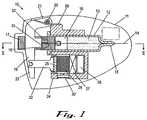
- FIG. 1is a sectional plan view of a first embodiment of a drug delivery device according to the invention
- FIGS. 2-5are schematic views of a detail of the embodiment of FIG. 1 shown at successive points in the operating cycle;
- FIG. 6is a sectional plan view of the embodiment of FIG. 1 , in use;
- FIGS. 7-11are sectional side views of a second embodiment of a device according to the invention, shown at successive points during its use;
- FIG. 12is a simplified sectional plan view of a third embodiment of a drug delivery device according to the invention.
- FIG. 13is a cross sectional side view of the embodiment of FIG. 12 , taken along the line XIII-XIII;
- FIG. 14is a sectional plan view of a fourth embodiment of a drug delivery device according to the invention.
- FIG. 15is a cross sectional side view of the embodiment of FIG. 12 , taken along the line XV-XV;
- FIG. 16is a graph showing the test results of an 80 hour test which plots delivery pressure and amount of drug delivered against time
- FIG. 17is an enlarged detail of a portion of the graph of FIG. 16 ;
- FIG. 18is a sectional plan view of a fifth embodiment of a drug delivery device according to the invention.
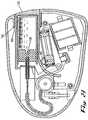
- FIG. 19is a sectional side view of the embodiment of FIG. 18 ;
- FIG. 20is a sectional plan view of the embodiment of FIG. 18 , as it is being prepared for use;
- FIG. 21is a sectional side view of the embodiment of FIG. 18 when ready for use;
- FIG. 22is a sectional plan view of a sixth embodiment of the drug delivery device according to the invention.
- FIG. 23is a sectional plan view of the embodiment of FIG. 22 when ready for use;
- FIG. 24is a cross-sectional view along line A-A of the embodiment of FIG. 22 ;
- FIG. 25is a cross-sectional view along line B-B of the embodiment of FIG. 22 ;
- FIG. 26is a schematic drawing representing the various parts of the gas generation sub-assembly of the embodiment of FIG. 22 .
- FIG. 1a drug delivery device according to the invention.
- the device 10comprises a housing 11 containing a cartridge 12 filled with a drug 13 .
- the cartridge 12is provided with a needle 14 extending from a first end 15 of the cartridge for delivery of drug 13 to a patient.
- a piston 16is slidably received in the cartridge 12 , such that when the piston 16 is pushed towards the first end 15 , drug is forced from the cartridge 12 out through the needle 14 .
- the piston 16is mounted on a ratchet bar 17 which is driven by a pawl 18 mounted on a reciprocable lever 19 .
- Lever 19is mounted on an axis 20 at one side 21 and is connected to a driving rod 22 at the other side 23 , whereby reciprocation of the driving rod 22 causes pawl 18 to reciprocate with respect to the ratchet bar 17 .
- thiscauses the ratchet bar 17 to advance stepwise towards the first end 15 of cartridge 12 and thereby drive the drug 13 from the cartridge.
- the driving rod 22is in connection with a flexible diaphragm 24 which defines a wall of a gas generation chamber 25 .
- a battery 26is connected via a microprocessor 27 to an electrolytic cell 28 which is operable to generate a gas into chamber 25 .
- the chamberexpands and causes the diaphragm 24 to move. This movement pushes the driving rod 22 in the direction away from the first end 15 of cartridge 12 .
- the movementis opposed by a return spring 29 which biases the lever 19 towards the first end 15 .
- the chamber 25is fully expanded and the supply of current from the battery 26 to the electrolytic cell 28 is switched off by the microprocessor 27 .
- a silicone membrane 30defines a wall of the chamber 25 .
- the membrane 30is slightly permeable and thus allows a controlled leakage of gas from the chamber 25 .
- the force of return spring 29will act to decompress the chamber 25 by gas leaking through membrane 30 .
- the lever 19 and hence the pawl 18will have made one complete reciprocation thereby advancing the ratchet bar 17 by a fixed step.
- the cyclemight be chosen to allow the delivery of a quantity of drug corresponding to the advancement of a single step of the ratchet bar 17 every five minutes.
- the electrolytic cell 28could be switched on for one minute and then switched off for four minutes. As long as the timing of the microprocessor is accurate, this will ensure that precisely one stepwise advance is made in that five minute period.
- the precision of device 10is to a certain extent independent of the exact quantity of gas generated because the ratchet bar 17 is quantised, i.e. it can only move by a fixed step (or number of steps) at a time.
- the membrane 30provides a controlled constant leakage from the system even during gas generation, other minor leaks which might affect the accuracy of conventional gas driven delivery devices are not important (although of course if the leak is bad enough the chamber will be unable to pressurise fully when the gas is generating).
- pawl 18is split in two halves, i.e. a longer half 31 , and a shorter half 32 .
- the pawl 18is a leaf spring which is biased down onto ratchet bar 17 .
- the halves 31 , 32 of the pawl 18are of unequal length.
- FIG. 2shows a cross-sectional enlarged view of a portion of the ratchet bar 17 which has a series of evenly spaced steps or teeth 33 , 34 .
- the difference in length between the halves 31 , 32 of the pawl 18is exactly half of the distance between adjacent teeth 33 , 34 on the ratchet bar 17 .
- each tooth 33 , 34has a sloped surface 35 having a peak 36 and a trough 37 , as shown in detail in FIG. 2A .
- the longer half 31 of the pawl 18presses against the sloped surface 35 of tooth 33 , midway between the peak 36 and trough 37 , and the shorter half 32 presses against the trough 37 of the adjacent tooth 34 .
- FIG. 6shows the device of FIG. 1 in operation at the completion of gas generation, and before the lever 19 has begun its return stroke.
- gas generation chamber 25has expanded by pushing the diaphragm 24 outwards, and the lever 19 is thus pivoted on its axis 20 against the force of the return spring 29 .
- the lever 19is driven back to the FIG. 1 position, a small volume of liquid drug 13 will be forced from the cartridge 12 .
- the device of FIG. 1delivers small volumes in a stepwise fashion, it is possible to achieve an extremely low delivery rate.
- the gas generator 25could be activated for 1 minute as previously described and then switched off for 59 minutes to give cycles of one hour duration.
- the device 10 of the present inventiondoes not require a system pressure to be maintained above atmospheric pressure.
- the volume of the gas generation chamber 25is small relative to the size of the device. This minimises variations in the volume of gas per stroke, and helps ensure a constant delivery rate.
- the device 10will generate in excess of 10-30% volume of gas over the required amount on each stroke so that the device can compensate of variations due to temperature, atmospheric pressure, materials used, etc. (The device will never drive the ratchet 10-30% further than necessary, since the ratchet can only move in fixed steps.) This extra gas is stored as an overpressure in the system and is of course released during the venting part of the cycle.
- FIG. 7shows a cross-sectional side view of a second alternative embodiment of the present invention, indicated generally at 50 .
- the device 50is similar in most respects to the first embodiment shown in FIG. 1 .
- the pawl 51is not split into two halves, so that it advances the ratchet bar 52 by full steps equal to the tooth length (“L”).
- the device 50is identical to the device 10 of FIG. 1 . It can be seen from FIG. 7 that the needle 53 of the device 50 (as with the FIG. 1 device) is bent at 90° to the axis of the cartridge 54 .
- the device 50 of FIG. 7is shown before use.
- a protective sheath 55is provided on the needle 53 and a displaceable lower cover 56 is hinged to the main housing 57 by a hinge (not shown).
- the displaceable lower cover 56 and the main housing 57are prevented from moving relative to one another by a safety tab 58 .
- the lower surface 61 of the displaceable cover 56is covered by a contact adhesive which is protected before application to the user by a protective liner 60 .
- the liner 60has a pull tab 59 to ease removal of the liner by the user immediately before application of the device 50 .
- the protective sheath 55is removed as indicated in FIG. 8 by grasping and pulling the pull tab 59 . This also causes the release liner 60 to be pulled away revealing the contact adhesive on the lower surface 61 of the displaceable cover 56 . The lower surface 61 is adhered to the user's skin. Then, the safety tab 58 is pulled away from the device 50 as shown in FIG. 9 .
- the main housing 57is then pressed towards the skin whereupon it snaps towards the displaceable cover 56 .
- the needle 53projects beyond the lower surface 61 to penetrate into the skin for subcutaneous drug delivery.
- the delivery mechanismis then actuated, either by the user, or more preferably, in automatic fashion by the microprocessor.
- the ratchet bar 52is advanced by the pawl 53 in stepwise manner as described above with regard to the operation of the first embodiment as shown in FIG. 1 .
- the usercan see the piston 62 through an aperture 63 in the main housing 57 as shown in FIG. 11 .
- the main housing 57is then pulled away from the skin whereupon it snaps away from the displaceable cover 56 and locks in this position by a locking mechanism (described in more detail in our U.S. Provisional Application No. 60/045,745) which prevents further actuation of the device, i.e. prevents the needle 53 from projecting beyond the displaceable cover 56 due to further relative movement of the main housing 57 and the displaceable cover 56 .
- FIG. 12there is indicated, generally at 70 , a further embodiment of a device according to the invention.
- a further embodiment of a device according to the inventionIn the illustration of this embodiment, only those details necessary to understand the differences relative to the devices of the first and second embodiments are shown, and thus the gas generation mechanism, for example is not shown.
- the ratchet barhas been replaced by a helical spring 71 .
- a lever 72is caused to reciprocate in identical manner to that previously described.
- a pair of resilient reciprocable fingers 73are mounted on the lever 72 and reciprocate as the lever reciprocates. These reciprocable fingers 73 are inclined in the direction of movement of the piston 74 as it empties the cartridge 75 . Thus, when they move in the direction in which they are inclined they tend to grip and push the coils of the helical spring 71 forward. As the helical spring 71 moves forward it slips past a pair of resilient fixed fingers 76 mounted directly in front of the reciprocable fingers 73 , and inclined in identical manner.
- FIG. 13shows a sectional side view of the device taken along the line XIII-XIII (in FIG. 12 ), in which the fixed fingers 76 and helical spring 71 are visible.
- the arrangement of reciprocable fingers 73 and fixed fingers 76act as a pawl and the helical spring 71 acts as a ratchet, such that on each reciprocation of the lever 72 , the helical spring 71 advances by an amount equal to a set number of coil diameters. Accordingly, as with previously described embodiments, precisely controlled delivery rates are achievable, and in particular, extremely low volume delivery rates are possible with this invention.
- One advantage of this embodimentis that because the helical spring 71 is curved within the device 70 , it does not have to project directly out of the cartridge 75 and thus a shorter device can be realised, or the shape of the device can be varied as required.
- FIG. 14A further embodiment of the present invention is shown in cross-sectional plan view in FIG. 14 .
- the device, indicated generally at 80is in many respects identical to the device of FIG. 1 but differs in that as well as the gas-driven lever 81 , a second manual lever 82 is provided.
- Manual lever 82is mounted on a common axis 83 with gas-driven lever 81 , as can be seen referring additionally to FIG. 15 .
- Manual lever 82passes under the ratchet bar 84 and also carries a second pawl 85 .
- Both the upper surface 86 and lower surface 87 of ratchet bar 84are provided with ratchet teeth, so that either gas-driven lever 81 or manual lever 82 can drive the ratchet bar 84 forward.
- gas-driven lever 81will drive the drug from the cartridge 88 , and in this mode, the ratchet bar 84 simply slides past the pawl member 85 on manual lever 82 as described previously.
- the manual lever 82can be actuated to advance the ratchet bar 84 by a pre-determined number of teeth.
- the manual lever 82can be seen to have an adjustable threaded locking member 89 which determines the extent of travel of the manual lever 82 , and hence the volume of the bolus delivery.
- FIG. 14the manual lever 82 can be seen to have an adjustable threaded locking member 89 which determines the extent of travel of the manual lever 82 , and hence the volume of the bolus delivery.
- the lever 82is prevented from travelling because the threaded member 89 is fully torqued, and this locks the lever 82 preventing it from being actuated.
- the lever 82is free to move inwards by an amount equal to the distance of axial travel of the threaded member 89 .
- the lever 82can then be actuated by depressing the threaded member 89 .
- the degree of travel of the lever 82is determined by the extent to which the threaded member 89 is turned, and by providing marked gradations on the threaded member 89 one can give the user visual control over the volume delivered in such a bolus dosage.
- the movement of the ratchet bar 84 under the action of the second pawl 85is independent of the primary pawl-and ratchet mechanism.
- the second pawl 85will, when actuated manually, advance the ratchet bar 84 by a whole number of steps.
- the ratchet bar 84slides under the pawl member 90 on gas-driven lever 81 , but this has no effect on the basal delivery rate or on the operation of the gas-driven delivery mechanism 80 .
- each individual ratchet mechanismis independent of the other, and bolus delivery can take place against the background basal rate without complication.
- FIG. 16is a graph of typical results achieved in a test of a device according to the invention, of the design shown in FIG. 1 .
- the graphshows two lines, namely the cumulative delivery of drug against time (the stepwise steadily ascending line), and the delivery pressure against time (the line consisting of a succession of sharp peaks and troughs).
- the devicewas tested over an 80 hour period (more than 3 days) and delivered just under 1.35 grams of drug solution in this time. This gives a delivery rate of less than 17 ⁇ g/hour. Furthermore, this delivery rate is absolutely constant, i.e. shows no deviation from a straight line. Accordingly, the device of FIG. 1 has a delivery rate whose accuracy is unmatched in the prior art, particularly for extremely slow delivery rates.
- FIG. 17shows a portion of the graph of FIG. 16 in greater detail, over a five hour period in the middle of the test. It can be seen that the pressure on each cycle immediately shoots up to a maximum, and then slowly falls off as gas is released through the silicone membrane.
- the delivery overpressurereaches over 400 mbar (0.4 atm or 40 kPa) on each cycle, and this assists in providing a constant delivery rate, since any minor needle blockages will be forced out, and variations in blood pressure (when intravenous delivery is effected will have a negligible effect on the delivery rate. This is to be contrasted with other low volume pumps which generally achieve low delivery rates with low delivery pressures.
- FIG. 18A further alternative embodiment is illustrated in FIG. 18 .
- the deviceindicated generally at 100 , has a housing 101 containing an internal needle 102 connected via a length of flexible tubing 103 to a delivery needle 104 (seen in sectional side view in FIG. 19 ).
- delivery needle 104is protected by a sheath 105 before use.
- Internal needle 102is also protected by a sheath 106 which is provided with a tab 107 extending the length of an internal bore 108 to the exterior of the housing 101 .
- Flexible tubing 103is carried on a ratchet bar 109 which can be driven to move the internal needle 102 in the direction of the internal bore 108 .
- a leaf spring 110 acting as a pawlis carried on a lever 111 to drive the ratchet bar in the manner previously described.
- the lever 11is driven by the expansion and contraction of an electrolytic cell 112 which is powered by batteries 113 .
- FIG. 20shows a step in the preparation of device 100 for use.
- the internal sheath 106has been removed and is no longer visible, thereby exposing internal needle which is in the centre of a cylindrical cup 114 .
- a drug cartridge 115is provided in the form of a cylindrical container 116 sealed at its open end 117 by a piston 118 slidably received in the container 116 .
- Bore 108is dimensioned to receive cartridge 115 , and a pair of resilient projections 119 inside the bore 108 hold the cartridge in place when it is pushed home within the bore.
- FIG. 21shows the device 100 when the cartridge 115 has been pushed home.
- Internal needle 102penetrates piston 118 , such that the internal needle 102 is in fluid communication with the drug inside the cartridge 115 .
- movement of the ratchet bar 109 into the cartridge 115causes the piston 118 to be pushed along the length of the cartridge 115 , and thereby pump drug through the internal needle 102 and flexible tubing 103 to the delivery needle 104 .
- the flexible tubing 103is pulled behind, thereby maintaining communication between internal needle 102 and delivery needle 104 .
- flexible tubing 103Another advantage of flexible tubing 103 is that it enables delivery needle 104 to be mounted at any point on the device, and thus the placement of the delivery needle in this embodiment is not constrained by the design of the other features.
- the configuration of lever 111 and the pivot 119 on which it is mountedcauses pawl 110 to advance ratchet bar 109 during the gas generation step rather than during the venting step.
- FIGS. 22-26A further embodiment is shown in FIGS. 22-26 .
- the embodiment 120comprises a housing 121 containing a cartridge 122 filled with a drug 123 .
- the cartridge 122is provided with a needle 124 for delivery of drug 123 to a patient.
- the cartridge 122includes a piston 125 which is slidably received in the cartridge 122 .
- the pistonhas an outer recess 126 for receiving a needle sterility cover 127 .
- the needle sterility cover 127covers a first end 128 of the needle 124 and prevents contamination thereto.
- a second end 129 of the needle 124is connected to a length of tubing 130 .
- the tubing 130has a first end 131 and a second end 132 , as shown in FIG. 24 .
- the tubing 130 second end 132is secured within an activation assembly 163 .
- a second needle 134is also secured to the activation assembly 163 .
- a drug pathway 133is machined into the activation assembly 163 , and the tubing 130 and second needle are secured within the activation assembly by means of an adhesive, preferably an ultra-violet bonding agent.
- a second needle sterility cover 135is slidably received on the exterior end 136 of the second needle 134 . Prior to use, the second needle sterility cover 135 is manually removed so as to uncover the exterior end 136 of the second needle 134 so that it is ready for penetration into the user's skin.
- the piston 125 and needle 124are mounted on a ratchet bar 137 having a multitude of stepped increments 138 thereon.
- the ratchet bar 137is moved by a leaf spring 139 integral with a reciprocating lever 140 .
- the lever 140is mounted on an axis 141 and has a return spring 142 that applies constant pressure to the lever 140 in a single direction.
- the lever 140rests against a gas generator sub-assembly 144 and moves in response to pressure differentiation created therein.
- the gas generation sub-assembly 144includes a pair of electrolytic cells 145 , 146 , as shown in FIG. 26 .
- the first cell 145is the propulsion cell.
- the propulsion cell 145has a first diaphragm 147 made of a low permeability material, such as bromo-butyl, ethylene propylene, or EPDM.
- the lever 140rests against the first diaphragm 147 .
- the second cell 146has a second diaphragm 148 thereon.
- the second diaphragm 148is made of a high permeability material, such as silicone rubber.
- the first cell 145has a hose 149 extending from the side of the first cell 145 to above the surface of the top of the second cell 146 .
- a gap 143is created between the end of the hose 149 and the top surface of the second cell 146 .
- the cells 145 , 146are activated with electrical energy from batteries 150 .
- Additional components in the present embodiment 120include a drug cartridge recess 151 , as shown in FIG. 23 .
- the drug cartridgehas a sleeve 152 for receiving and supporting the cartridge 122 and ensuring safe and accurate operation of the device 120 .
- the sleeve 152is slidably received into the recess 151 .
- the sleeve 152has a lip 153 on the exterior at the insertion end 154 of the sleeve.
- the recess 151has a shelf 155 for receiving the lip 153 of the sleeve when the cartridge 122 is fully inserted, as shown in FIG. 21 .
- a cartridge receiving channel 156is located within the housing 121 and is proximate to the recess 151 .
- the channelprovides further support for the cartridge when it is inserted within the device 120 .
- the channelincludes an outer edge 157 , an inner edge 158 and an arched portion 159 .
- the outer and inner edgesare parallel and align with the cartridge recess to guide and support the cartridge 122 upon insertion and during use.
- the arched portion 159 of the channelis integral with the inner edge 158 and is curved away from the cartridge and ratchet assembly. Prior to operation, the arched portion 159 rests against a depressable button 160 that is part of the gas generating sub-assembly 137 .
- the button 160has a puncturing device on the inner surface thereof.
- the puncturing mechanismbreaks a seal 161 of the compartment 162 containing the chemical entity used in the electrolytic cells 145 , 146 of the gas generating sub-assembly 144 , as shown in FIG. 22 .
- the chemical entityis typically potassium chloride, and in the present embodiment, it is preferably in a less viscous form so as to enable the liquid to move to gaseous form more quickly.
- FIG. 24shows a cross-sectional view of manual activation assembly 163 along line A-A.
- the activation assembly 163includes a spring loaded start button 164 which is slidably received within a button channel 165 .
- the button 164is maintained in an outward position by means of a helical spring 166 , located and supported in the button channel 165 .
- the helical spring 166is loaded both axially and torsionally within the button channel 165 .
- 25is a cross-sectional view of the activation assembly along line B-B, which shows a pin 169 which moves within a groove 170 in the button channel 165 from a first, pre-operational position [shown as position 169 A], to a second, operational position [ 169 B], to a third, locked position [ 169 C].
- the button 164has a finger 167 extending therefrom.
- the finger 167is located directly above a deflectable electrical contact 168 .
- the finger 167contacts the electrical contact 168 and causes it to deflect, thus causing electrical communication between the contacts and initiating operation of the device 120 .
- the embodiment 120is supplied with a drug cartridge 122 .
- the cartridge 122filled with drug 123 is fully inserted into the cartridge recess 151 .
- the lip 153 of the sleeve 152lockably engages with the shelf 155 and prevents the cartridge 122 from being removed.
- the needle sterility cover 127engages with the piston outer recess 126 , and the tip of the needle pierces the needle sterility cover 127 and piston 125 and moves into the interior of the cartridge, as shown in FIG. 23 .
- the travel of the cartridgeends when the sleeve lip engages with the shelf and the inner and outer edges of the channel.
- the cartridge edgecontacts the arched portion of the channel 156 causing it to deflect away from the cartridge.
- Such deflectionapplies pressure to the depressable button which depresses and pierces the container of chemical used to generate the gas within the electrolytic cells.
- the device 120is then applied by the user or health care worker to the skin.
- the deviceis then activated when the start button 164 is depressed causing the finger 167 to contact the electrical contact 168 thus closing an electrical circuit which initiates gas generation in the sub-assembly.
- the button 164is depressed, the torsional force of the helical spring 166 prevents the button from springing back up and locks the button, and second needle 134 in position [ 169 B] during operation, as shown in FIG. 25 .
- both cellsWhen the cells 145 , 146 are activated with electrical energy from the batteries 150 , both cells begin to generate gas.
- the first cell 145builds pressure quickly because of the low permeability of the first diaphragm 147 , as shown in FIG. 26A . However, pressure is released through the hose and exits into the atmosphere within the housing 121 .
- the second diaphragm 148deforms outwardly, closing the gap 143 between the hose and the top surface of the second cell, as shown in FIG. 26B . When this is closed, the gas from the first cell can no longer escape into the atmosphere, causing the first diaphragm to elastically deform outwardly.
- This deformationapplies pressure to the lever 140 , as shown in FIG. 26C .
- pressureWhen pressure is applied on the lever, it causes the leaf spring to move from a first stepped increment 138 A to a second increment 138 B. This movement causes the piston 125 to move further along the length of the drug cartridge 122 , decreasing the volume of drug 123 in the cartridge and moving such drug into the patient via the needle 124 .
- the gas-generation sub-assemblyis designed in such a way so as to provide maximum efficiency in the cycle of moving the leaf spring from a first increment 138 A to a second increment 138 B.
- the low permeability of the first diaphragm 147allows the pressure to build in the first cell 145 and thus results in quick deformation of the diaphragm and movement of the reciprocating piston 125 .
- the integration between the first and second cells, 145 , 146is important in order to quickly release the pressure within the first cell 145 after the leaf spring has been moved forward.
- the hose 149 between the first and second cellconnects the two cells during deflection and provides first for the build up of pressure.
- the electrical connection to the batteries 150is disconnected, or decreased.
- the second diaphragmloses height and recreates the gap 143 , thus allowing gas from the first cell to quickly bleed off and return to a low pressure state to begin the next cycle. It should be noted that it is possible to maintain a minimum current level within the cells in order to keep a minimum level of pressure in the cells so as not to start the build up of pressure from a lower point than necessary, thus maximizing the efficiency of the cycle time.
- the current needed during the gas generation portion of the cyclemay range from 5-7 milliampers, and the current to maintain the minimum level of pressure may range from 30-50 microampers.
- This cell designhas enabled the cycle time to decrease from 20 minutes to 5 minutes in the present embodiment.
- the length between activating and deactivating the electrolytic cellsmay be controlled by means of a microprocessor, along with the use of different diaphragm materials.
- the cycle time to move the leaf spring a single incrementmay be adjusted depending upon the delivery rate desired.
- the number and size of incrementsmay be altered to provide further flexibility in the delivery rate.
- the helical spring 166which is torsionally loaded, forces the pin 169 to move from the operation position [ 169 B] to a locked post-operational position [ 169 C]. This causes the entire activation assembly to retract and the exterior end 136 of the second needle 134 to be recessed into the housing, thereby avoiding any accidental injury or attempted further use of the device 120 .
- the number of sterile componentshas been minimized so as to eliminate the need to sterilize the entire device.
- the following componentsare sterilized as an assembly prior to being assembled into the device.
- the sterilized sub-assemblyincludes the needle sterility cover 127 , the needle 124 , the tubing 130 , the start button 164 , the drug pathway 133 , the second needle 134 , and the penetrating needle sterility protector 135 .
- drugused herein includes but is not limited to peptides or proteins, hormones, analgesics, anti-migraine agents, anti-coagulant agents, narcotic antagonists, chelating agents, anti-anginal agents, chemotherapy agents, sedatives, anti-neoplastics, prostaglandins, antidiuretic agents, anti-sense agents, oligonucleotides, mucosal vaccines, gene-based medicines and permeability and enhancing agents.
- Typical drugsinclude peptides, proteins or hormones such as insulin, calcitonin, calcitonin gene regulating protein, atrial natriuretic protein, colony stimulating factor, betaseron, erythropoietin (EPO), interferons such as ⁇ , ⁇ or ⁇ interferon, somatropin, somatotropin, somastostatin, insulin-like growth factor (somatomedins), luteinizing hormone releasing hormone (LHRH), tissue plasminogen activator (TPA), growth hormone releasing hormone (GHRH), oxytocin, estradiol, growth hormones, leuprolide acetate, factor VIII, interleukins such as interleukin-2, and analogues thereof; analgesics such as fentanyl, sufentanil, butorphanol, buprenorphine, levorphanol, morphine, hydromorphone, hydrocodone, oxymorphone, methadone, lido
- antiulcer agentssuch as but not limited to cimetidine, and ranitidine; antibiotics; anticonvulsants; antiinflammatories; antifungals; antipsychotics; corticosteroids; immunosuppressants; electrolytes; nutritional agents and vitamins; general anesthetics; antianxiety agents, such as but not limited to compazine; and diagnostic agents.
Landscapes
- Health & Medical Sciences (AREA)
- Life Sciences & Earth Sciences (AREA)
- Veterinary Medicine (AREA)
- Public Health (AREA)
- General Health & Medical Sciences (AREA)
- Animal Behavior & Ethology (AREA)
- Heart & Thoracic Surgery (AREA)
- Hematology (AREA)
- Biomedical Technology (AREA)
- Anesthesiology (AREA)
- Engineering & Computer Science (AREA)
- Vascular Medicine (AREA)
- Dermatology (AREA)
- Chemical & Material Sciences (AREA)
- Medicinal Chemistry (AREA)
- Pharmacology & Pharmacy (AREA)
- Epidemiology (AREA)
- Inorganic Chemistry (AREA)
- Infusion, Injection, And Reservoir Apparatuses (AREA)
- Vending Machines For Individual Products (AREA)
- Medicines Containing Plant Substances (AREA)
- Acyclic And Carbocyclic Compounds In Medicinal Compositions (AREA)
Abstract
Description
Claims (3)
Priority Applications (7)
| Application Number | Priority Date | Filing Date | Title |
|---|---|---|---|
| US13/184,479US8361028B2 (en) | 1998-03-23 | 2011-07-15 | Drug delivery device |
| US13/617,041US20130079747A1 (en) | 1998-03-23 | 2012-09-14 | Drug delivery device |
| US13/617,126US9132231B2 (en) | 1998-03-23 | 2012-09-14 | Drug delivery device |
| US13/617,397US20130012874A1 (en) | 1998-03-23 | 2012-09-14 | Drug delivery device |
| US13/616,896US20130012872A1 (en) | 1998-03-23 | 2012-09-14 | Drug delivery device |
| US13/617,579US20130012875A1 (en) | 1998-03-23 | 2012-09-14 | Drug delivery device |
| US14/833,684US20160106912A1 (en) | 1998-03-23 | 2015-08-24 | Drug delivery device |
Applications Claiming Priority (7)
| Application Number | Priority Date | Filing Date | Title |
|---|---|---|---|
| US7904798P | 1998-03-23 | 1998-03-23 | |
| IE980211 | 1998-03-23 | ||
| IE980211AIE980211A1 (en) | 1998-03-23 | 1998-03-23 | Improved drug delivery device. |
| US09/275,464US6595956B1 (en) | 1998-03-23 | 1999-03-23 | Drug delivery device |
| US10/461,040US7384413B2 (en) | 1998-03-23 | 2003-06-13 | Drug delivery device |
| US12/121,545US7998117B2 (en) | 1998-03-23 | 2008-05-15 | Drug delivery device |
| US13/184,479US8361028B2 (en) | 1998-03-23 | 2011-07-15 | Drug delivery device |
Related Parent Applications (1)
| Application Number | Title | Priority Date | Filing Date |
|---|---|---|---|
| US12/121,545ContinuationUS7998117B2 (en) | 1998-03-23 | 2008-05-15 | Drug delivery device |
Related Child Applications (5)
| Application Number | Title | Priority Date | Filing Date |
|---|---|---|---|
| US13/617,126ContinuationUS9132231B2 (en) | 1998-03-23 | 2012-09-14 | Drug delivery device |
| US13/616,896ContinuationUS20130012872A1 (en) | 1998-03-23 | 2012-09-14 | Drug delivery device |
| US13/617,397ContinuationUS20130012874A1 (en) | 1998-03-23 | 2012-09-14 | Drug delivery device |
| US13/617,579ContinuationUS20130012875A1 (en) | 1998-03-23 | 2012-09-14 | Drug delivery device |
| US13/617,041ContinuationUS20130079747A1 (en) | 1998-03-23 | 2012-09-14 | Drug delivery device |
Publications (2)
| Publication Number | Publication Date |
|---|---|
| US20110275999A1 US20110275999A1 (en) | 2011-11-10 |
| US8361028B2true US8361028B2 (en) | 2013-01-29 |
Family
ID=26320168
Family Applications (11)
| Application Number | Title | Priority Date | Filing Date |
|---|---|---|---|
| US09/275,464Expired - LifetimeUS6595956B1 (en) | 1998-03-23 | 1999-03-23 | Drug delivery device |
| US10/461,040Expired - LifetimeUS7384413B2 (en) | 1998-03-23 | 2003-06-13 | Drug delivery device |
| US12/121,545Expired - Fee RelatedUS7998117B2 (en) | 1998-03-23 | 2008-05-15 | Drug delivery device |
| US13/184,479Expired - Fee RelatedUS8361028B2 (en) | 1998-03-23 | 2011-07-15 | Drug delivery device |
| US13/184,473Expired - Fee RelatedUS8361027B2 (en) | 1998-03-23 | 2011-07-15 | Drug delivery device |
| US13/617,397AbandonedUS20130012874A1 (en) | 1998-03-23 | 2012-09-14 | Drug delivery device |
| US13/617,579AbandonedUS20130012875A1 (en) | 1998-03-23 | 2012-09-14 | Drug delivery device |
| US13/617,041AbandonedUS20130079747A1 (en) | 1998-03-23 | 2012-09-14 | Drug delivery device |
| US13/616,896AbandonedUS20130012872A1 (en) | 1998-03-23 | 2012-09-14 | Drug delivery device |
| US13/617,126Expired - Fee RelatedUS9132231B2 (en) | 1998-03-23 | 2012-09-14 | Drug delivery device |
| US14/833,684AbandonedUS20160106912A1 (en) | 1998-03-23 | 2015-08-24 | Drug delivery device |
Family Applications Before (3)
| Application Number | Title | Priority Date | Filing Date |
|---|---|---|---|
| US09/275,464Expired - LifetimeUS6595956B1 (en) | 1998-03-23 | 1999-03-23 | Drug delivery device |
| US10/461,040Expired - LifetimeUS7384413B2 (en) | 1998-03-23 | 2003-06-13 | Drug delivery device |
| US12/121,545Expired - Fee RelatedUS7998117B2 (en) | 1998-03-23 | 2008-05-15 | Drug delivery device |
Family Applications After (7)
| Application Number | Title | Priority Date | Filing Date |
|---|---|---|---|
| US13/184,473Expired - Fee RelatedUS8361027B2 (en) | 1998-03-23 | 2011-07-15 | Drug delivery device |
| US13/617,397AbandonedUS20130012874A1 (en) | 1998-03-23 | 2012-09-14 | Drug delivery device |
| US13/617,579AbandonedUS20130012875A1 (en) | 1998-03-23 | 2012-09-14 | Drug delivery device |
| US13/617,041AbandonedUS20130079747A1 (en) | 1998-03-23 | 2012-09-14 | Drug delivery device |
| US13/616,896AbandonedUS20130012872A1 (en) | 1998-03-23 | 2012-09-14 | Drug delivery device |
| US13/617,126Expired - Fee RelatedUS9132231B2 (en) | 1998-03-23 | 2012-09-14 | Drug delivery device |
| US14/833,684AbandonedUS20160106912A1 (en) | 1998-03-23 | 2015-08-24 | Drug delivery device |
Country Status (9)
| Country | Link |
|---|---|
| US (11) | US6595956B1 (en) |
| EP (1) | EP1064035B1 (en) |
| JP (1) | JP4425465B2 (en) |
| AT (1) | ATE254938T1 (en) |
| AU (1) | AU3050499A (en) |
| CA (1) | CA2325004A1 (en) |
| DE (1) | DE69913111T2 (en) |
| TW (1) | TW426531B (en) |
| WO (1) | WO1999048546A1 (en) |
Cited By (15)
| Publication number | Priority date | Publication date | Assignee | Title |
|---|---|---|---|---|
| US20130012875A1 (en)* | 1998-03-23 | 2013-01-10 | Alkermes Pharma Ireland Limited | Drug delivery device |
| US8945071B2 (en) | 2010-09-02 | 2015-02-03 | Becton, Dickinson And Company | Self-injection device having needle cover with activation preventer |
| US9795534B2 (en) | 2015-03-04 | 2017-10-24 | Medimop Medical Projects Ltd. | Compliant coupling assembly for cartridge coupling of a drug delivery device |
| US9884154B2 (en) | 2016-06-28 | 2018-02-06 | Darcy Eleniak | Medication injecting apparatus |
| US9919097B2 (en) | 2009-12-16 | 2018-03-20 | Becton, Dickinson And Company | Self-injection device |
| US10182969B2 (en) | 2015-03-10 | 2019-01-22 | Regeneron Pharmaceuticals, Inc. | Aseptic piercing system and method |
| US10251813B2 (en) | 2015-03-04 | 2019-04-09 | West Pharma. Services IL, Ltd. | Flexibly mounted cartridge alignment collar for drug delivery device |
| US11167086B2 (en) | 2008-09-15 | 2021-11-09 | West Pharma. Services IL, Ltd. | Stabilized pen injector |
| US11403306B2 (en) | 2017-06-21 | 2022-08-02 | Citrix Systems, Inc. | Systems and methods of sharing a database across multiple deployments and services |
| US11547801B2 (en) | 2017-05-05 | 2023-01-10 | Regeneron Pharmaceuticals, Inc. | Auto-injector |
| US11819666B2 (en) | 2017-05-30 | 2023-11-21 | West Pharma. Services IL, Ltd. | Modular drive train for wearable injector |
| USD1007676S1 (en) | 2021-11-16 | 2023-12-12 | Regeneron Pharmaceuticals, Inc. | Wearable autoinjector |
| US12097357B2 (en) | 2008-09-15 | 2024-09-24 | West Pharma. Services IL, Ltd. | Stabilized pen injector |
| US12161838B2 (en) | 2017-01-17 | 2024-12-10 | West Pharma. Services IL, Ltd. | Bent spring powered injector |
| US12357767B2 (en) | 2016-08-01 | 2025-07-15 | West Pharma. Services IL, Ltd. | Partial door closure prevention spring |
Families Citing this family (349)
| Publication number | Priority date | Publication date | Assignee | Title |
|---|---|---|---|---|
| US5968547A (en) | 1997-02-24 | 1999-10-19 | Euro-Celtique, S.A. | Method of providing sustained analgesia with buprenorphine |
| US6663602B2 (en) | 2000-06-16 | 2003-12-16 | Novo Nordisk A/S | Injection device |
| DE10029325A1 (en)* | 2000-06-20 | 2002-01-03 | Peter Lell | Needle-free injection device with pyrotechnic drive |
| AU2002241567A1 (en)* | 2000-11-30 | 2002-07-24 | Biovalve Technologies, Inc. | Fluid delivery and measurement systems and methods |
| US7544188B2 (en)* | 2001-07-19 | 2009-06-09 | Intelliject, Inc. | Medical injector |
| GB0118419D0 (en)* | 2001-07-28 | 2001-09-19 | Owen Mumford Ltd | Improvements relating to injection devices |
| TWI222370B (en)* | 2001-12-14 | 2004-10-21 | Roche Diagnostics Gmbh | Needleless hypodermic injection device |
| EP3351277A1 (en) | 2002-03-26 | 2018-07-25 | Becton, Dickinson and Company | Multi-stage fluid delivery device and method |
| US6912417B1 (en) | 2002-04-05 | 2005-06-28 | Ichor Medical Systmes, Inc. | Method and apparatus for delivery of therapeutic agents |
| US6979316B1 (en)* | 2002-05-23 | 2005-12-27 | Seedlings Life Science Ventures Llc | Apparatus and method for rapid auto-injection of medication |
| CN100479875C (en)* | 2002-07-22 | 2009-04-22 | 贝克顿·迪金森公司 | Patch-like infusion device |
| AU2003245872A1 (en) | 2002-07-24 | 2004-02-09 | M 2 Medical A/S | An infusion pump system, an infusion pump unit and an infusion pump |
| CN1723053A (en)* | 2002-09-12 | 2006-01-18 | 儿童医院医疗中心 | Method and device for painless drug injection |
| CN1726059A (en) | 2002-11-05 | 2006-01-25 | M2医药有限公司 | Disposable wearable insulin dispensing device, combination of the device and a program controller and method for controlling the operation of the device |
| WO2004056412A2 (en) | 2002-12-23 | 2004-07-08 | M2 Medical A/S | A disposable, wearable insulin dispensing device, a combination of such a device and a programming controller and a method of controlling the operation of such a device |
| US7413748B2 (en)* | 2002-12-13 | 2008-08-19 | Purdue Pharma L.P. | Transdermal buprenorphine to treat pain in sickle cell crisis |
| WO2004094823A2 (en) | 2003-04-23 | 2004-11-04 | Biovalve Technologies, Inc. | Hydraulically actuated pump for long duration medicament administration |
| ATE392223T1 (en) | 2003-05-08 | 2008-05-15 | Novo Nordisk As | INTERNAL NEEDLE INTRODUCER |
| JP4509100B2 (en) | 2003-05-08 | 2010-07-21 | ノボ・ノルデイスク・エー/エス | Infusion device attachable to skin with removable needle insertion actuation |
| EP1475113A1 (en)* | 2003-05-08 | 2004-11-10 | Novo Nordisk A/S | External needle inserter |
| EP1502613A1 (en) | 2003-08-01 | 2005-02-02 | Novo Nordisk A/S | Needle device with retraction means |
| EP3695862A1 (en) | 2003-08-12 | 2020-08-19 | Becton, Dickinson and Company | Patch-like infusion device |
| ATE448828T1 (en)* | 2003-10-27 | 2009-12-15 | Univ Basel | TRANSDERMAL DRUG DELIVERY SYSTEM |
| SG179411A1 (en)* | 2003-11-06 | 2012-04-27 | Lifescan Inc | Drug delivery pen with event notification means |
| US7731691B2 (en) | 2003-11-10 | 2010-06-08 | Smiths Medical Asd, Inc. | Subcutaneous infusion device and device for insertion of a cannula of an infusion device and method |
| US7850658B2 (en)* | 2003-11-10 | 2010-12-14 | Smiths Medical Asd, Inc. | Subcutaneous infusion device and method including release feature for adhesive portion |
| WO2005079440A2 (en)* | 2004-02-17 | 2005-09-01 | Children's Hospital Medical Center | Improved injection devicew for administering a vaccine |
| SI1729848T1 (en) | 2004-03-08 | 2015-08-31 | Ichor Medical Systems Inc. | Improved apparatus for electrically mediated delivery of therapeutic agents |
| CN100586495C (en)* | 2004-03-30 | 2010-02-03 | 诺和诺德公司 | Actuator system comprising lever mechanism |
| JP2007530860A (en)* | 2004-03-30 | 2007-11-01 | ノボ・ノルデイスク・エー/エス | Actuator system having detection means |
| US9089636B2 (en) | 2004-07-02 | 2015-07-28 | Valeritas, Inc. | Methods and devices for delivering GLP-1 and uses thereof |
| US20060024140A1 (en)* | 2004-07-30 | 2006-02-02 | Wolff Edward C | Removable tap chasers and tap systems including the same |
| US8252321B2 (en) | 2004-09-13 | 2012-08-28 | Chrono Therapeutics, Inc. | Biosynchronous transdermal drug delivery for longevity, anti-aging, fatigue management, obesity, weight loss, weight management, delivery of nutraceuticals, and the treatment of hyperglycemia, alzheimer's disease, sleep disorders, parkinson's disease, aids, epilepsy, attention deficit disorder, nicotine addiction, cancer, headache and pain control, asthma, angina, hypertension, depression, cold, flu and the like |
| US7780981B2 (en) | 2004-09-13 | 2010-08-24 | Chrono Therapeutics, Inc. | Biosynchronous transdermal drug delivery |
| ATE444090T1 (en) | 2004-10-21 | 2009-10-15 | Novo Nordisk As | SELECTION MECHANISM FOR A ROTARY PIN |
| US10737028B2 (en) | 2004-11-22 | 2020-08-11 | Kaleo, Inc. | Devices, systems and methods for medicament delivery |
| US7648482B2 (en) | 2004-11-22 | 2010-01-19 | Intelliject, Inc. | Devices, systems, and methods for medicament delivery |
| US11590286B2 (en) | 2004-11-22 | 2023-02-28 | Kaleo, Inc. | Devices, systems and methods for medicament delivery |
| US7648483B2 (en) | 2004-11-22 | 2010-01-19 | Intelliject, Inc. | Devices, systems and methods for medicament delivery |
| US7947017B2 (en) | 2004-11-22 | 2011-05-24 | Intelliject, Inc. | Devices, systems and methods for medicament delivery |
| WO2006057636A1 (en) | 2004-11-22 | 2006-06-01 | Intelliject, Llc | Devices, systems, and methods for medicament delivery |
| US8167841B2 (en) | 2005-01-24 | 2012-05-01 | Novo Nordisk A/S | Transcutaneous device assembly |
| US8206360B2 (en) | 2005-02-01 | 2012-06-26 | Intelliject, Inc. | Devices, systems and methods for medicament delivery |
| US8361026B2 (en) | 2005-02-01 | 2013-01-29 | Intelliject, Inc. | Apparatus and methods for self-administration of vaccines and other medicaments |
| US8231573B2 (en) | 2005-02-01 | 2012-07-31 | Intelliject, Inc. | Medicament delivery device having an electronic circuit system |
| AU2006210865B2 (en) | 2005-02-01 | 2008-12-04 | Kaleo, Inc. | Devices, systems, and methods for medicament delivery |
| US7731686B2 (en) | 2005-02-01 | 2010-06-08 | Intelliject, Inc. | Devices, systems and methods for medicament delivery |
| US9022980B2 (en) | 2005-02-01 | 2015-05-05 | Kaleo, Inc. | Medical injector simulation device |
| EP1877115A1 (en) | 2005-04-06 | 2008-01-16 | M 2 Medical A/S | An actuator |
| US20080097291A1 (en)* | 2006-08-23 | 2008-04-24 | Hanson Ian B | Infusion pumps and methods and delivery devices and methods with same |
| US7699833B2 (en) | 2005-05-06 | 2010-04-20 | Moberg Sheldon B | Pump assembly and method for infusion device |
| US8840586B2 (en)* | 2006-08-23 | 2014-09-23 | Medtronic Minimed, Inc. | Systems and methods allowing for reservoir filling and infusion medium delivery |
| US7905868B2 (en) | 2006-08-23 | 2011-03-15 | Medtronic Minimed, Inc. | Infusion medium delivery device and method with drive device for driving plunger in reservoir |
| US8277415B2 (en)* | 2006-08-23 | 2012-10-02 | Medtronic Minimed, Inc. | Infusion medium delivery device and method with drive device for driving plunger in reservoir |
| US8512288B2 (en)* | 2006-08-23 | 2013-08-20 | Medtronic Minimed, Inc. | Infusion medium delivery device and method with drive device for driving plunger in reservoir |
| US8137314B2 (en)* | 2006-08-23 | 2012-03-20 | Medtronic Minimed, Inc. | Infusion medium delivery device and method with compressible or curved reservoir or conduit |
| US8372040B2 (en) | 2005-05-24 | 2013-02-12 | Chrono Therapeutics, Inc. | Portable drug delivery device including a detachable and replaceable administration or dosing element |
| US8637127B2 (en) | 2005-06-27 | 2014-01-28 | Kennametal Inc. | Composite article with coolant channels and tool fabrication method |
| US7687156B2 (en) | 2005-08-18 | 2010-03-30 | Tdy Industries, Inc. | Composite cutting inserts and methods of making the same |
| EP1754498A1 (en)* | 2005-08-19 | 2007-02-21 | Roche Diagnostics GmbH | Driving device for an injection or infusion device |
| US7534226B2 (en) | 2005-09-26 | 2009-05-19 | M2 Group Holdings, Inc. | Dispensing fluid from an infusion pump system |
| US8105279B2 (en) | 2005-09-26 | 2012-01-31 | M2 Group Holdings, Inc. | Dispensing fluid from an infusion pump system |
| DK1933902T3 (en) | 2005-09-26 | 2015-03-23 | Asante Solutions Inc | Infusion Pump WITH A DRIVE THAT HAVE AN PALLEGEME- AND CONGEST HAGE-COMBINATION |
| US8409142B2 (en) | 2005-09-26 | 2013-04-02 | Asante Solutions, Inc. | Operating an infusion pump system |
| WO2007056592A2 (en) | 2005-11-08 | 2007-05-18 | M2 Medical A/S | Method and system for manual and autonomous control of an infusion pump |
| US11497846B2 (en) | 2006-02-09 | 2022-11-15 | Deka Products Limited Partnership | Patch-sized fluid delivery systems and methods |
| US11478623B2 (en) | 2006-02-09 | 2022-10-25 | Deka Products Limited Partnership | Infusion pump assembly |
| EP3165247B1 (en) | 2006-02-09 | 2020-10-28 | DEKA Products Limited Partnership | Pumping fluid delivery systems and methods using force application assembley |
| US12070574B2 (en) | 2006-02-09 | 2024-08-27 | Deka Products Limited Partnership | Apparatus, systems and methods for an infusion pump assembly |
| US12274857B2 (en) | 2006-02-09 | 2025-04-15 | Deka Products Limited Partnership | Method and system for shape-memory alloy wire control |
| US12370305B2 (en) | 2006-02-09 | 2025-07-29 | Deka Products Limited Partnership | Patch-sized fluid delivery systems and methods |
| US12151080B2 (en) | 2006-02-09 | 2024-11-26 | Deka Products Limited Partnership | Adhesive and peripheral systems and methods for medical devices |
| US10010669B2 (en) | 2006-02-09 | 2018-07-03 | Deka Products Limited Partnership | Systems and methods for fluid delivery |
| US11027058B2 (en) | 2006-02-09 | 2021-06-08 | Deka Products Limited Partnership | Infusion pump assembly |
| US11364335B2 (en) | 2006-02-09 | 2022-06-21 | Deka Products Limited Partnership | Apparatus, system and method for fluid delivery |
| EP1997233B1 (en) | 2006-03-13 | 2014-03-05 | Novo Nordisk A/S | Secure pairing of electronic devices using dual means of communication |
| WO2007115039A2 (en)* | 2006-03-30 | 2007-10-11 | Valeritas, Llc | Multi-cartridge fluid delivery device |
| ATE512278T1 (en) | 2006-04-27 | 2011-06-15 | Tdy Ind Inc | MODULAR EARTH DRILLING BIT WITH FIXED CUTTER AND MODULAR EARTH DRILLING BIT BODY WITH FIXED CUTTER |
| ATE458517T1 (en) | 2006-05-16 | 2010-03-15 | Novo Nordisk As | TRANSMISSION MECHANISM FOR AN INJECTION DEVICE |
| JP5253387B2 (en) | 2006-05-18 | 2013-07-31 | ノボ・ノルデイスク・エー/エス | Injection device with mode locking means |
| EP2032188A1 (en) | 2006-06-06 | 2009-03-11 | Novo Nordisk A/S | Assembly comprising skin-mountable device and packaging therefore |
| US7794434B2 (en)* | 2006-08-23 | 2010-09-14 | Medtronic Minimed, Inc. | Systems and methods allowing for reservoir filling and infusion medium delivery |
| US7682338B2 (en)* | 2006-08-23 | 2010-03-23 | Medtronic Minimed, Inc. | Infusion medium delivery system, device and method with needle inserter and needle inserter device and method |
| US20080051765A1 (en)* | 2006-08-23 | 2008-02-28 | Medtronic Minimed, Inc. | Systems and methods allowing for reservoir filling and infusion medium delivery |
| US7811262B2 (en)* | 2006-08-23 | 2010-10-12 | Medtronic Minimed, Inc. | Systems and methods allowing for reservoir filling and infusion medium delivery |
| US7828764B2 (en)* | 2006-08-23 | 2010-11-09 | Medtronic Minimed, Inc. | Systems and methods allowing for reservoir filling and infusion medium delivery |
| CN102764893B (en) | 2006-10-25 | 2015-06-17 | 肯纳金属公司 | Articles having improved resistance to thermal cracking |
| EP2125075A2 (en) | 2007-01-22 | 2009-12-02 | Intelliject, Inc. | Medical injector with compliance tracking and monitoring |
| CA2677667A1 (en) | 2007-02-09 | 2008-08-14 | Deka Products Limited Partnership | Automated insertion assembly |
| US8512882B2 (en) | 2007-02-19 | 2013-08-20 | TDY Industries, LLC | Carbide cutting insert |
| US7846551B2 (en) | 2007-03-16 | 2010-12-07 | Tdy Industries, Inc. | Composite articles |
| US20100152674A1 (en)* | 2007-04-30 | 2010-06-17 | Medtronic Minimed, Inc | Needle inserting and fluid flow connection for infusion medium delivery system |
| US7963954B2 (en) | 2007-04-30 | 2011-06-21 | Medtronic Minimed, Inc. | Automated filling systems and methods |
| US8434528B2 (en) | 2007-04-30 | 2013-05-07 | Medtronic Minimed, Inc. | Systems and methods for reservoir filling |
| US8597243B2 (en) | 2007-04-30 | 2013-12-03 | Medtronic Minimed, Inc. | Systems and methods allowing for reservoir air bubble management |
| US8323250B2 (en) | 2007-04-30 | 2012-12-04 | Medtronic Minimed, Inc. | Adhesive patch systems and methods |
| JP5102350B2 (en) | 2007-04-30 | 2012-12-19 | メドトロニック ミニメド インコーポレイテッド | Reservoir filling / bubble management / infusion medium delivery system and method using the system |
| US7959715B2 (en) | 2007-04-30 | 2011-06-14 | Medtronic Minimed, Inc. | Systems and methods allowing for reservoir air bubble management |
| US8613725B2 (en) | 2007-04-30 | 2013-12-24 | Medtronic Minimed, Inc. | Reservoir systems and methods |
| US7981102B2 (en) | 2007-05-21 | 2011-07-19 | Asante Solutions, Inc. | Removable controller for an infusion pump |
| US7833196B2 (en) | 2007-05-21 | 2010-11-16 | Asante Solutions, Inc. | Illumination instrument for an infusion pump |
| US7892199B2 (en) | 2007-05-21 | 2011-02-22 | Asante Solutions, Inc. | Occlusion sensing for an infusion pump |
| US20090018512A1 (en)* | 2007-07-13 | 2009-01-15 | Charles Steven T | Pneumatically-Powered Ophthalmic Injector |
| EP2263720B1 (en)* | 2007-08-20 | 2012-06-13 | Mallinckrodt LLC | Fluid driven medical injectors |
| US7717903B2 (en) | 2007-09-06 | 2010-05-18 | M2 Group Holdings, Inc. | Operating an infusion pump system |
| US8032226B2 (en) | 2007-09-07 | 2011-10-04 | Asante Solutions, Inc. | User profile backup system for an infusion pump device |
| US8287514B2 (en) | 2007-09-07 | 2012-10-16 | Asante Solutions, Inc. | Power management techniques for an infusion pump system |
| US7935076B2 (en) | 2007-09-07 | 2011-05-03 | Asante Solutions, Inc. | Activity sensing techniques for an infusion pump system |
| US10420880B2 (en) | 2007-10-02 | 2019-09-24 | West Pharma. Services IL, Ltd. | Key for securing components of a drug delivery system during assembly and/or transport and methods of using same |
| BRPI0817907B8 (en) | 2007-10-02 | 2021-06-22 | Lamodel Ltd | apparatus for administering a substance to an individual |
| US9656019B2 (en) | 2007-10-02 | 2017-05-23 | Medimop Medical Projects Ltd. | Apparatuses for securing components of a drug delivery system during transport and methods of using same |
| US9345836B2 (en) | 2007-10-02 | 2016-05-24 | Medimop Medical Projects Ltd. | Disengagement resistant telescoping assembly and unidirectional method of assembly for such |
| US7967795B1 (en) | 2010-01-19 | 2011-06-28 | Lamodel Ltd. | Cartridge interface assembly with driving plunger |
| CN101888859B (en) | 2007-10-31 | 2014-09-17 | 诺沃-诺迪斯克有限公司 | Non-porous material as sterilization barrier |
| US9456955B2 (en) | 2007-12-31 | 2016-10-04 | Deka Products Limited Partnership | Apparatus, system and method for fluid delivery |
| US9526830B2 (en) | 2007-12-31 | 2016-12-27 | Deka Products Limited Partnership | Wearable pump assembly |
| US8900188B2 (en) | 2007-12-31 | 2014-12-02 | Deka Products Limited Partnership | Split ring resonator antenna adapted for use in wirelessly controlled medical device |
| US10080704B2 (en) | 2007-12-31 | 2018-09-25 | Deka Products Limited Partnership | Apparatus, system and method for fluid delivery |
| CA2919786C (en) | 2007-12-31 | 2019-10-22 | Deka Products Limited Partnership | Infusion pump assembly |
| US10188787B2 (en) | 2007-12-31 | 2019-01-29 | Deka Products Limited Partnership | Apparatus, system and method for fluid delivery |
| US8881774B2 (en) | 2007-12-31 | 2014-11-11 | Deka Research & Development Corp. | Apparatus, system and method for fluid delivery |
| US8986253B2 (en) | 2008-01-25 | 2015-03-24 | Tandem Diabetes Care, Inc. | Two chamber pumps and related methods |
| US8603009B2 (en)* | 2008-03-07 | 2013-12-10 | Becton, Dickinson And Company | Flashback blood collection needle |
| DK3260145T3 (en)* | 2008-04-09 | 2020-02-17 | Hoffmann La Roche | Fluid level sensor for a modular, skin adhesive medical fluid delivery system |
| US8021344B2 (en) | 2008-07-28 | 2011-09-20 | Intelliject, Inc. | Medicament delivery device configured to produce an audible output |
| USD994111S1 (en) | 2008-05-12 | 2023-08-01 | Kaleo, Inc. | Medicament delivery device cover |
| UA103620C2 (en) | 2008-06-02 | 2013-11-11 | ТИ ДИ УАЙ ИНДАСТРИЗ, ЭлЭлСи | Composite sintered powder metal article and method for its production |
| US8790439B2 (en) | 2008-06-02 | 2014-07-29 | Kennametal Inc. | Composite sintered powder metal articles |
| DE102008030270A1 (en)* | 2008-06-19 | 2009-12-24 | Arzneimittel Gmbh Apotheker Vetter & Co. Ravensburg | Device having at least one chamber for receiving a medicament or a sample volume |
| US7959598B2 (en) | 2008-08-20 | 2011-06-14 | Asante Solutions, Inc. | Infusion pump systems and methods |
| US8025112B2 (en) | 2008-08-22 | 2011-09-27 | Tdy Industries, Inc. | Earth-boring bits and other parts including cemented carbide |
| US8322465B2 (en) | 2008-08-22 | 2012-12-04 | TDY Industries, LLC | Earth-boring bit parts including hybrid cemented carbides and methods of making the same |
| US8408421B2 (en) | 2008-09-16 | 2013-04-02 | Tandem Diabetes Care, Inc. | Flow regulating stopcocks and related methods |
| CA2737461A1 (en) | 2008-09-19 | 2010-03-25 | Tandem Diabetes Care, Inc. | Solute concentration measurement device and related methods |
| US20100145305A1 (en)* | 2008-11-10 | 2010-06-10 | Ruth Alon | Low volume accurate injector |
| US20100130958A1 (en)* | 2008-11-26 | 2010-05-27 | David Kang | Device and Methods for Subcutaneous Delivery of High Viscosity Fluids |
| JP5600115B2 (en) | 2008-12-09 | 2014-10-01 | ベクトン・ディキンソン・アンド・カンパニー | Drug delivery system to increase lever and gear force for high pressure injection system |
| US8152779B2 (en)* | 2008-12-30 | 2012-04-10 | Medimop Medical Projects Ltd. | Needle assembly for drug pump |
| US8667996B2 (en) | 2009-05-04 | 2014-03-11 | Valeritas, Inc. | Fluid transfer device |
| US8272816B2 (en) | 2009-05-12 | 2012-09-25 | TDY Industries, LLC | Composite cemented carbide rotary cutting tools and rotary cutting tool blanks |
| US8308096B2 (en) | 2009-07-14 | 2012-11-13 | TDY Industries, LLC | Reinforced roll and method of making same |
| WO2011008966A2 (en) | 2009-07-15 | 2011-01-20 | Deka Products Limited Partnership | Apparatus, systems and methods for an infusion pump assembly |
| EP2724739B1 (en) | 2009-07-30 | 2015-07-01 | Tandem Diabetes Care, Inc. | Portable infusion pump system |
| US8440314B2 (en) | 2009-08-25 | 2013-05-14 | TDY Industries, LLC | Coated cutting tools having a platinum group metal concentration gradient and related processes |
| US10071196B2 (en) | 2012-05-15 | 2018-09-11 | West Pharma. Services IL, Ltd. | Method for selectively powering a battery-operated drug-delivery device and device therefor |
| US8157769B2 (en) | 2009-09-15 | 2012-04-17 | Medimop Medical Projects Ltd. | Cartridge insertion assembly for drug delivery system |
| US10071198B2 (en) | 2012-11-02 | 2018-09-11 | West Pharma. Servicees IL, Ltd. | Adhesive structure for medical device |
| US9643236B2 (en) | 2009-11-11 | 2017-05-09 | Landis Solutions Llc | Thread rolling die and method of making same |
| DK2512560T3 (en) | 2009-12-16 | 2018-07-16 | Becton Dickinson Co | Even injector device |
| JP5650241B2 (en) | 2009-12-16 | 2015-01-07 | ベクトン・ディキンソン・アンド・カンパニーBecton, Dickinson And Company | Self injection device |
| JP5650755B2 (en) | 2009-12-16 | 2015-01-07 | ベクトン・ディキンソン・アンド・カンパニーBecton, Dickinson And Company | Self injection device |
| CN102753221B (en) | 2009-12-16 | 2017-04-26 | 贝克顿·迪金森公司 | self-injection device |
| WO2011075103A1 (en) | 2009-12-16 | 2011-06-23 | Becton, Dickinson And Company | Self-injection device |
| US8579859B2 (en)* | 2009-12-26 | 2013-11-12 | Board Of Regents, The University Of Texas System | Fluid balance monitoring system with fluid infusion pump for medical treatment |
| US8348898B2 (en) | 2010-01-19 | 2013-01-08 | Medimop Medical Projects Ltd. | Automatic needle for drug pump |
| CA3033439C (en) | 2010-01-22 | 2021-04-06 | Deka Products Limited Partnership | Method and system for shape-memory alloy wire control |
| BR112012023689A2 (en) | 2010-03-19 | 2016-08-23 | Halozyme Inc | gas pressurized medication dispensing device |
| AU2015227439B2 (en)* | 2010-04-21 | 2018-04-12 | Abbvie Biotechnology Ltd | Wearable automatic injection device for controlled delivery of therapeutic agents |
| NZ702172A (en)* | 2010-04-21 | 2016-03-31 | Abbvie Biotechnology Ltd | Wearable automatic injection device for controlled delivery of therapeutic agents |
| EP2569031B1 (en)* | 2010-05-10 | 2017-10-11 | Medimop Medical Projects Ltd. | Low volume accurate injector |
| BR112012029642B1 (en) | 2010-05-20 | 2020-05-26 | Becton, Dickinson And Company | DRUG ADMINISTRATION DEVICE |
| SG194370A1 (en) | 2010-06-07 | 2013-11-29 | Amgen Inc | Drug delivery device |
| CN102971026A (en)* | 2010-06-30 | 2013-03-13 | 泰尔茂株式会社 | Drug injection apparatus and drug container |
| JP2012029723A (en)* | 2010-07-28 | 2012-02-16 | Terumo Corp | Injection needle assembly and drug injection apparatus |
| US9381300B2 (en)* | 2010-09-24 | 2016-07-05 | Perqflo, Llc | Infusion pumps |
| US8915879B2 (en) | 2010-09-24 | 2014-12-23 | Perqflo, Llc | Infusion pumps |
| US9498573B2 (en) | 2010-09-24 | 2016-11-22 | Perqflo, Llc | Infusion pumps |
| US20120158104A1 (en) | 2010-10-26 | 2012-06-21 | Medtronic Ardian Luxembourg S.A.R.L. | Neuromodulation cryotherapeutic devices and associated systems and methods |
| US8905972B2 (en) | 2010-11-20 | 2014-12-09 | Perqflo, Llc | Infusion pumps |
| US8535268B2 (en) | 2010-12-22 | 2013-09-17 | Alcon Research, Ltd. | Device for at least one of injection or aspiration |
| US8627816B2 (en) | 2011-02-28 | 2014-01-14 | Intelliject, Inc. | Medicament delivery device for administration of opioid antagonists including formulations for naloxone |
| US9173999B2 (en) | 2011-01-26 | 2015-11-03 | Kaleo, Inc. | Devices and methods for delivering medicaments from a multi-chamber container |
| US8939943B2 (en) | 2011-01-26 | 2015-01-27 | Kaleo, Inc. | Medicament delivery device for administration of opioid antagonists including formulations for naloxone |
| US8852152B2 (en) | 2011-02-09 | 2014-10-07 | Asante Solutions, Inc. | Infusion pump systems and methods |
| US8454581B2 (en) | 2011-03-16 | 2013-06-04 | Asante Solutions, Inc. | Infusion pump systems and methods |
| USD702834S1 (en) | 2011-03-22 | 2014-04-15 | Medimop Medical Projects Ltd. | Cartridge for use in injection device |
| AU2012245211B2 (en)* | 2011-04-21 | 2016-03-10 | Abbvie Inc. | Wearable automatic injection device |
| EP2729148A4 (en) | 2011-07-06 | 2015-04-22 | Parkinson S Inst | COMPOSITIONS AND METHODS FOR TREATING SYMPTOMS IN PATIENTS WITH PARKINSON'S DISEASE |
| RU2467770C1 (en) | 2011-08-01 | 2012-11-27 | Общество С Ограниченной Ответственностью "Форас Лаб" | Device for painless and low-invasive parenteral introduction of pharmaceutical preparations and blood sampling |
| US8800848B2 (en) | 2011-08-31 | 2014-08-12 | Kennametal Inc. | Methods of forming wear resistant layers on metallic surfaces |
| US9707335B2 (en) | 2011-09-02 | 2017-07-18 | Unitract Syringe Pty Ltd | Drive mechanism for drug delivery pumps with integrated status indication |
| US11173244B2 (en) | 2011-09-02 | 2021-11-16 | Unl Holdings Llc | Drive mechanism for drug delivery pumps with integrated status indication |
| US9814832B2 (en) | 2011-09-02 | 2017-11-14 | Unl Holdings Llc | Drive mechanism for drug delivery pumps with integrated status indication |
| EP2731641B1 (en) | 2011-09-02 | 2021-09-29 | UNL Holdings LLC | Drive mechanism for drug delivery pumps with integrated status indication |
| CA2845379C (en) | 2011-09-02 | 2019-08-06 | Unitract Syringe Pty Ltd | Insertion mechanism for a drug delivery pump |
| CN103764197B (en)* | 2011-09-07 | 2017-03-15 | 3M创新有限公司 | Delivery system for hollow microneedle arrays |
| US8808230B2 (en) | 2011-09-07 | 2014-08-19 | Asante Solutions, Inc. | Occlusion detection for an infusion pump system |
| ES2566179T5 (en)* | 2011-09-13 | 2019-11-14 | Unitract Syringe Pty Ltd | Connection of sterile fluid passage to medication containers for medication release pumps |
| US9016406B2 (en) | 2011-09-22 | 2015-04-28 | Kennametal Inc. | Cutting inserts for earth-boring bits |
| DK3045187T3 (en) | 2011-10-14 | 2019-06-11 | Amgen Inc | INJECTOR AND COLLECTION PROCEDURE |
| JP6069351B2 (en) | 2011-12-29 | 2017-02-01 | ノボ・ノルデイスク・エー/エス | Torsion spring type automatic syringe with dial-up / dial-down administration mechanism |
| US9937317B2 (en)* | 2012-01-30 | 2018-04-10 | Ipsumpro, S.L. | Modified medical syringe with a flow regulator for the administration of local anaesthetic |
| EP2809375B1 (en) | 2012-01-31 | 2021-08-11 | Medimop Medical Projects Ltd. | Time dependent drug delivery apparatus |
| US11524151B2 (en) | 2012-03-07 | 2022-12-13 | Deka Products Limited Partnership | Apparatus, system and method for fluid delivery |
| KR20140135736A (en)* | 2012-03-12 | 2014-11-26 | 유니트랙트 시린지 피티와이 엘티디 | Fill-finish cartridges for sterile fluid pathway assemblies and drug delivery devices incorporating fill-finish cartridges |
| US9072827B2 (en) | 2012-03-26 | 2015-07-07 | Medimop Medical Projects Ltd. | Fail safe point protector for needle safety flap |
| US9463280B2 (en) | 2012-03-26 | 2016-10-11 | Medimop Medical Projects Ltd. | Motion activated septum puncturing drug delivery device |
| US10668213B2 (en) | 2012-03-26 | 2020-06-02 | West Pharma. Services IL, Ltd. | Motion activated mechanisms for a drug delivery device |
| EP4406568A3 (en) | 2012-03-30 | 2024-10-16 | Insulet Corporation | Fluid delivery device with transcutaneous access tool, insertion mechanism and blood glucose monitoring for use therewith |
| US9180242B2 (en) | 2012-05-17 | 2015-11-10 | Tandem Diabetes Care, Inc. | Methods and devices for multiple fluid transfer |
| US9522235B2 (en) | 2012-05-22 | 2016-12-20 | Kaleo, Inc. | Devices and methods for delivering medicaments from a multi-chamber container |
| US9555186B2 (en) | 2012-06-05 | 2017-01-31 | Tandem Diabetes Care, Inc. | Infusion pump system with disposable cartridge having pressure venting and pressure feedback |
| EP2674177B1 (en)* | 2012-06-14 | 2021-06-30 | Stevanato Group S.P.A. | Medicament infusion device |
| US10238796B2 (en) | 2012-06-27 | 2019-03-26 | Sanofi-Aventis Deutschland Gmbh | Linear actor arrangement |
| US8454557B1 (en) | 2012-07-19 | 2013-06-04 | Asante Solutions, Inc. | Infusion pump system and method |
| US8454562B1 (en) | 2012-07-20 | 2013-06-04 | Asante Solutions, Inc. | Infusion pump system and method |
| ES2637229T3 (en) | 2012-08-29 | 2017-10-11 | Unitract Syringe Pty Ltd | Controlled drive mechanisms for medication delivery pumps |
| USD745142S1 (en) | 2012-08-30 | 2015-12-08 | Unitract Syringe Pty Ltd | Drug delivery pump |
| CA3206182A1 (en)* | 2012-11-21 | 2014-05-30 | Amgen Inc. | Drug delivery device including insertion member and reservoir |
| US9427523B2 (en) | 2012-12-10 | 2016-08-30 | Bigfoot Biomedical, Inc. | Infusion pump system and method |
| US20140276536A1 (en) | 2013-03-14 | 2014-09-18 | Asante Solutions, Inc. | Infusion Pump System and Methods |
| GB2526948A (en) | 2012-12-27 | 2015-12-09 | Kaleo Inc | Systems for locating and interacting with medicament delivery devices |
| US9421323B2 (en) | 2013-01-03 | 2016-08-23 | Medimop Medical Projects Ltd. | Door and doorstop for portable one use drug delivery apparatus |
| US10105487B2 (en) | 2013-01-24 | 2018-10-23 | Chrono Therapeutics Inc. | Optimized bio-synchronous bioactive agent delivery system |
| USD723157S1 (en) | 2013-03-12 | 2015-02-24 | Unitract Syringe Pty Ltd | Drug delivery pump |
| US9802030B2 (en) | 2013-01-25 | 2017-10-31 | Unl Holdings Llc | Integrated sliding seal fluid pathway connection and drug containers for drug delivery pumps |
| US9446186B2 (en) | 2013-03-01 | 2016-09-20 | Bigfoot Biomedical, Inc. | Operating an infusion pump system |
| US9173998B2 (en) | 2013-03-14 | 2015-11-03 | Tandem Diabetes Care, Inc. | System and method for detecting occlusions in an infusion pump |
| SG11201507878SA (en) | 2013-03-22 | 2015-10-29 | Amgen Inc | Injector and method of assembly |
| DK2983746T3 (en) | 2013-04-10 | 2020-03-23 | Sanofi Sa | INJECTION DEVICE AND PROCEDURE FOR COLLECTION |
| US9011164B2 (en) | 2013-04-30 | 2015-04-21 | Medimop Medical Projects Ltd. | Clip contact for easy installation of printed circuit board PCB |
| US9889256B2 (en) | 2013-05-03 | 2018-02-13 | Medimop Medical Projects Ltd. | Sensing a status of an infuser based on sensing motor control and power input |
| EP2999504A1 (en) | 2013-05-21 | 2016-03-30 | Novo Nordisk A/S | Drug delivery device with piston rod coupling |
| WO2014187813A1 (en) | 2013-05-21 | 2014-11-27 | Novo Nordisk A/S | Frontloaded drug delivery device with dynamic axial stop feature |
| US9457141B2 (en) | 2013-06-03 | 2016-10-04 | Bigfoot Biomedical, Inc. | Infusion pump system and method |
| US9446187B2 (en) | 2013-06-03 | 2016-09-20 | Bigfoot Biomedical, Inc. | Infusion pump system and method |
| WO2014204457A1 (en)* | 2013-06-19 | 2014-12-24 | HARISH, Ziv | Palm-based injector actuation and safety surfaces |
| US9617020B2 (en) | 2013-07-03 | 2017-04-11 | Deka Products Limited Partnership | Apparatus, system and method for fluid delivery |
| US9561324B2 (en) | 2013-07-19 | 2017-02-07 | Bigfoot Biomedical, Inc. | Infusion pump system and method |
| AU2014308659B2 (en) | 2013-08-23 | 2018-11-01 | Unl Holdings Llc | Integrated pierceable seal fluid pathway connection and drug containers for drug delivery pumps |
| BR112016008946B1 (en) | 2013-10-24 | 2022-12-27 | Amgen Inc | INJECTORS AND METHOD FOR ASSEMBLING THE INJECTORS |
| US10569015B2 (en) | 2013-12-02 | 2020-02-25 | Bigfoot Biomedical, Inc. | Infusion pump system and method |
| US9474862B2 (en) | 2013-12-16 | 2016-10-25 | Jessica Walsh | Wearable medication administration device |
| JP2016540581A (en)* | 2013-12-20 | 2016-12-28 | サノフィ−アベンティス・ドイチュラント・ゲゼルシャフト・ミット・ベシュレンクテル・ハフツング | Disposable delivery assembly for drug delivery device |
| CN110947050A (en)* | 2014-01-31 | 2020-04-03 | 瓦莱里塔斯公司 | Mobile base engine for fluid transfer device |
| CN106470717B (en) | 2014-06-03 | 2020-09-11 | 安姆根有限公司 | Drug delivery system and method of use |
| US9629901B2 (en) | 2014-07-01 | 2017-04-25 | Bigfoot Biomedical, Inc. | Glucagon administration system and methods |
| CN106572904B (en)* | 2014-07-15 | 2019-06-18 | 爱尔康制药有限公司 | Intraocular lens inserter with temperature-compensating |
| US9517307B2 (en) | 2014-07-18 | 2016-12-13 | Kaleo, Inc. | Devices and methods for delivering opioid antagonists including formulations for naloxone |
| US10137246B2 (en) | 2014-08-06 | 2018-11-27 | Bigfoot Biomedical, Inc. | Infusion pump assembly and method |
| US9919096B2 (en) | 2014-08-26 | 2018-03-20 | Bigfoot Biomedical, Inc. | Infusion pump system and method |
| EP3200851A1 (en) | 2014-09-29 | 2017-08-09 | Unitract Syringe Pty Ltd | Rigid needle insertion mechanism for a drug delivery pump |
| US12178992B2 (en) | 2014-09-30 | 2024-12-31 | Medtronic Minimed, Inc. | Different disposable assemblies for the same reusable assembly |
| US10159786B2 (en) | 2014-09-30 | 2018-12-25 | Perqflo, Llc | Hybrid ambulatory infusion pumps |
| TWD174176S (en) | 2014-11-07 | 2016-03-01 | 優尼翠克注射器有限公司 | Portion of drug delivery device (2) |
| JP6716566B2 (en) | 2014-12-19 | 2020-07-01 | アムジエン・インコーポレーテツド | Drug delivery device with proximity sensor |
| US11357916B2 (en) | 2014-12-19 | 2022-06-14 | Amgen Inc. | Drug delivery device with live button or user interface field |
| WO2016123406A1 (en) | 2015-01-28 | 2016-08-04 | Chrono Therapeutics Inc. | Drug delivery methods and systems |
| US10737016B2 (en) | 2015-02-18 | 2020-08-11 | Medtronic Minimed, Inc. | Ambulatory infusion pumps and reservoir assemblies for use with same |
| DE102015102350B3 (en)* | 2015-02-19 | 2016-05-04 | Sartorius Stedim Biotech Gmbh | Filtration device for liquid samples |
| CN107530502B (en) | 2015-02-20 | 2021-01-15 | 里珍纳龙药品有限公司 | Syringe system, piston sealing system, stopper system |
| EP3267875A4 (en) | 2015-03-12 | 2018-12-05 | Chrono Therapeutics Inc. | Craving input and support system |
| US10695495B2 (en) | 2015-03-24 | 2020-06-30 | Kaleo, Inc. | Devices and methods for delivering a lyophilized medicament |
| US10293120B2 (en) | 2015-04-10 | 2019-05-21 | West Pharma. Services IL, Ltd. | Redundant injection device status indication |
| US9744297B2 (en) | 2015-04-10 | 2017-08-29 | Medimop Medical Projects Ltd. | Needle cannula position as an input to operational control of an injection device |
| CN107534887B (en)* | 2015-04-22 | 2021-02-12 | 高通股份有限公司 | Correlation and combination of MDT metrics with QoE metrics |
| US9878097B2 (en) | 2015-04-29 | 2018-01-30 | Bigfoot Biomedical, Inc. | Operating an infusion pump system |
| US10149943B2 (en) | 2015-05-29 | 2018-12-11 | West Pharma. Services IL, Ltd. | Linear rotation stabilizer for a telescoping syringe stopper driverdriving assembly |
| CN113181477B (en) | 2015-06-04 | 2023-07-14 | 麦迪麦珀医疗工程有限公司 | Cartridge insertion for drug delivery device |
| USD794770S1 (en) | 2015-06-26 | 2017-08-15 | Unitract Syringe Pty Ltd | Drug delivery pump |
| CA2990950A1 (en) | 2015-06-30 | 2017-01-05 | Kaleo, Inc. | Auto-injectors for administration of a medicament within a prefilled syringe |
| CN107847666B (en)* | 2015-07-07 | 2020-06-02 | 伟创力有限责任公司 | Aseptic patch pump |
| USD794771S1 (en) | 2015-07-10 | 2017-08-15 | Unitract Syringe Pty Ltd. | Drug delivery pump |
| US9987432B2 (en) | 2015-09-22 | 2018-06-05 | West Pharma. Services IL, Ltd. | Rotation resistant friction adapter for plunger driver of drug delivery device |
| US10086145B2 (en) | 2015-09-22 | 2018-10-02 | West Pharma Services Il, Ltd. | Rotation resistant friction adapter for plunger driver of drug delivery device |
| US10576207B2 (en) | 2015-10-09 | 2020-03-03 | West Pharma. Services IL, Ltd. | Angled syringe patch injector |
| US11318254B2 (en) | 2015-10-09 | 2022-05-03 | West Pharma. Services IL, Ltd. | Injector needle cap remover |
| AU2016385454B2 (en) | 2016-01-05 | 2021-12-16 | Bigfoot Biomedical, Inc. | Operating multi-modal medicine delivery systems |
| US10449294B1 (en) | 2016-01-05 | 2019-10-22 | Bigfoot Biomedical, Inc. | Operating an infusion pump system |
| EP3374905A1 (en) | 2016-01-13 | 2018-09-19 | Bigfoot Biomedical, Inc. | User interface for diabetes management system |
| HK1256995A1 (en) | 2016-01-14 | 2019-10-11 | Bigfoot Biomedical, Inc. | Occlusion resolution in medication delivery devices, systems, and methods |
| US10806859B2 (en) | 2016-01-14 | 2020-10-20 | Bigfoot Biomedical, Inc. | Adjusting insulin delivery rates |
| JP6885960B2 (en) | 2016-01-21 | 2021-06-16 | ウェスト ファーマ サービシーズ イスラエル リミテッド | Drug delivery device with visual indicators |
| US10646643B2 (en) | 2016-01-21 | 2020-05-12 | West Pharma. Services IL, Ltd. | Needle insertion and retraction mechanism |
| EP3711793B1 (en) | 2016-01-21 | 2021-12-01 | West Pharma Services IL, Ltd. | A method of connecting a cartridge to an automatic injector |
| EP3413954B1 (en) | 2016-02-12 | 2025-09-03 | Medtronic MiniMed, Inc. | Ambulatory infusion pump and assemblies for use with same |
| USD809134S1 (en) | 2016-03-10 | 2018-01-30 | Bigfoot Biomedical, Inc. | Infusion pump assembly |
| US11389597B2 (en) | 2016-03-16 | 2022-07-19 | West Pharma. Services IL, Ltd. | Staged telescopic screw assembly having different visual indicators |
| US10376647B2 (en) | 2016-03-18 | 2019-08-13 | West Pharma. Services IL, Ltd. | Anti-rotation mechanism for telescopic screw assembly |
| KR102535764B1 (en) | 2016-03-28 | 2023-05-30 | 아이커 메디칼 시스템스 인코포레이티드 | Apparatus for delivery of therapeutic agents |
| EP4442297A3 (en) | 2016-04-29 | 2025-01-01 | ICU Medical, Inc. | Subcutaneous insertion systems, devices and related methods |
| US12383166B2 (en) | 2016-05-23 | 2025-08-12 | Insulet Corporation | Insulin delivery system and methods with risk-based set points |
| US10363374B2 (en) | 2016-05-26 | 2019-07-30 | Insulet Corporation | Multi-dose drug delivery device |
| CN109310831B (en) | 2016-06-02 | 2021-11-23 | 西医药服务以色列有限公司 | Three position needle retraction |
| US11338090B2 (en) | 2016-08-01 | 2022-05-24 | West Pharma. Services IL, Ltd. | Anti-rotation cartridge pin |
| IL264404B (en) | 2016-08-08 | 2022-07-01 | Unitract Syringe Pty Ltd | Drug delivery device and method for connecting a fluid flow path |
| US10363372B2 (en) | 2016-08-12 | 2019-07-30 | Insulet Corporation | Plunger for drug delivery device |
| EP3730169B1 (en) | 2016-08-14 | 2023-08-02 | Insulet Corporation | Drug delivery device with detection of position of the plunger |
| US10695487B2 (en) | 2016-08-30 | 2020-06-30 | Unl Holdings Llc | Controlled delivery drive mechanisms for drug delivery pumps |
| AU2017335762B2 (en) | 2016-09-27 | 2022-03-17 | Bigfoot Biomedical, Inc. | Medicine injection and disease management systems, devices, and methods |
| WO2018067645A1 (en) | 2016-10-07 | 2018-04-12 | Insulet Corporation | Multi-stage delivery system |
| US10780217B2 (en) | 2016-11-10 | 2020-09-22 | Insulet Corporation | Ratchet drive for on body delivery system |
| USD836769S1 (en) | 2016-12-12 | 2018-12-25 | Bigfoot Biomedical, Inc. | Insulin delivery controller |
| EP3500161A4 (en) | 2016-12-12 | 2020-01-08 | Bigfoot Biomedical, Inc. | ALARMS AND WARNINGS FOR MEDICINE DELIVERY DEVICES AND RELATED SYSTEMS AND METHODS |
| WO2018119218A1 (en) | 2016-12-23 | 2018-06-28 | Kaleo, Inc. | Medicament delivery device and methods for delivering drugs to infants and children |
| WO2018129304A1 (en) | 2017-01-06 | 2018-07-12 | Chrono Therapeutics Inc. | Transdermal drug delivery devices and methods |
| US10881792B2 (en) | 2017-01-13 | 2021-01-05 | Bigfoot Biomedical, Inc. | System and method for adjusting insulin delivery |
| US10500334B2 (en) | 2017-01-13 | 2019-12-10 | Bigfoot Biomedical, Inc. | System and method for adjusting insulin delivery |
| US10758675B2 (en) | 2017-01-13 | 2020-09-01 | Bigfoot Biomedical, Inc. | System and method for adjusting insulin delivery |
| EP3568859A1 (en) | 2017-01-13 | 2019-11-20 | Bigfoot Biomedical, Inc. | Insulin delivery methods, systems and devices |
| US20190351135A1 (en)* | 2017-01-15 | 2019-11-21 | E3D Agricultural Cooperative Association Ltd | Transfusion pump |
| CA3046354A1 (en) | 2017-01-17 | 2018-07-26 | Kaleo, Inc. | Medicament delivery devices with wireless connectivity and event detection |
| WO2018136699A1 (en) | 2017-01-19 | 2018-07-26 | Insulet Corporation | Cartridge hold-up volume reduction |
| JP2020508803A (en) | 2017-03-06 | 2020-03-26 | アムジエン・インコーポレーテツド | Drug delivery device with anti-actuation feature |
| US10695485B2 (en) | 2017-03-07 | 2020-06-30 | Insulet Corporation | Very high volume user filled drug delivery device |
| USD874471S1 (en) | 2017-06-08 | 2020-02-04 | Insulet Corporation | Display screen with a graphical user interface |
| USD839294S1 (en) | 2017-06-16 | 2019-01-29 | Bigfoot Biomedical, Inc. | Display screen with graphical user interface for closed-loop medication delivery |
| EP3651647A1 (en) | 2017-07-13 | 2020-05-20 | Bigfoot Biomedical, Inc. | Multi-scale display of blood glucose information |
| US10973978B2 (en) | 2017-08-03 | 2021-04-13 | Insulet Corporation | Fluid flow regulation arrangements for drug delivery devices |
| US11280327B2 (en) | 2017-08-03 | 2022-03-22 | Insulet Corporation | Micro piston pump |
| US11786668B2 (en) | 2017-09-25 | 2023-10-17 | Insulet Corporation | Drug delivery devices, systems, and methods with force transfer elements |
| US11813426B2 (en)* | 2017-10-06 | 2023-11-14 | Amgen Inc. | Drug delivery device including seal member for needle of syringe |
| JP7402799B2 (en) | 2017-12-22 | 2023-12-21 | ウェスト ファーマ サービシーズ イスラエル リミテッド | Syringes available with different cartridge sizes |
| USD928199S1 (en) | 2018-04-02 | 2021-08-17 | Bigfoot Biomedical, Inc. | Medication delivery device with icons |
| US11583633B2 (en) | 2018-04-03 | 2023-02-21 | Amgen Inc. | Systems and methods for delayed drug delivery |
| US11931551B2 (en)* | 2018-04-09 | 2024-03-19 | Becton Dickinson France | Medical injection system |
| CA3098372A1 (en) | 2018-04-24 | 2019-10-31 | Deka Products Limited Partnership | Apparatus and system for fluid delivery |
| CA3101966A1 (en) | 2018-05-29 | 2019-12-05 | Morningside Venture Investments Limited | Drug delivery methods and systems |
| US10874803B2 (en) | 2018-05-31 | 2020-12-29 | Insulet Corporation | Drug cartridge with drive system |
| US11229736B2 (en) | 2018-06-06 | 2022-01-25 | Insulet Corporation | Linear shuttle pump for drug delivery |
| US11929160B2 (en) | 2018-07-16 | 2024-03-12 | Kaleo, Inc. | Medicament delivery devices with wireless connectivity and compliance detection |
| JP2022507660A (en) | 2018-11-16 | 2022-01-18 | モーニングサイド ベンチャー インベストメンツ リミテッド | Temperature-controlled transdermal drug delivery system |
| US11446435B2 (en) | 2018-11-28 | 2022-09-20 | Insulet Corporation | Drug delivery shuttle pump system and valve assembly |
| CN109512543B (en)* | 2018-12-19 | 2021-04-27 | 周庆芬 | Automated pet injection device |
| USD920343S1 (en) | 2019-01-09 | 2021-05-25 | Bigfoot Biomedical, Inc. | Display screen or portion thereof with graphical user interface associated with insulin delivery |
| US12403247B2 (en)* | 2019-05-17 | 2025-09-02 | Medtrum Technologies Inc. | Drug infusion device |
| WO2020233484A1 (en)* | 2019-05-17 | 2020-11-26 | Medtrum Technologies Inc. | Drug infusion device with multiple infusion modes |
| WO2020233486A1 (en)* | 2019-05-17 | 2020-11-26 | Medtrum Technologies Inc. | Bilaterally driven drug infusion device with multiple infusion modes |
| CN111939387B (en)* | 2019-05-17 | 2022-12-09 | 上海移宇科技股份有限公司 | Drug infusion device with multiple infusion modes |
| US11587839B2 (en) | 2019-06-27 | 2023-02-21 | Analog Devices, Inc. | Device with chemical reaction chamber |
| WO2021012852A1 (en)* | 2019-07-19 | 2021-01-28 | Medtrum Technologies Inc. | Unilateral-driven medical device with infusion and detection integrated |
| WO2021012075A1 (en)* | 2019-07-19 | 2021-01-28 | Medtrum Technologies Inc. | Integrated drug infusion device |
| CN112295050B (en)* | 2019-08-01 | 2023-06-06 | 上海移宇科技股份有限公司 | Drives and Drug Infusion Devices |
| US20220218895A1 (en)* | 2019-08-01 | 2022-07-14 | Medtrum Technologies Inc. | Driving apparatus and drug infusion device |
| CA3145580A1 (en) | 2019-08-09 | 2021-02-18 | Kaleo, Inc. | Devices and methods for delivery of substances within a prefilled syringe |
| US20220362469A1 (en)* | 2019-10-31 | 2022-11-17 | Eoflow Co., Ltd. | Cartridge module, liquid medicine discharge assembly, and liquid medicine injection device comprising same |
| US11369735B2 (en) | 2019-11-05 | 2022-06-28 | Insulet Corporation | Component positioning of a linear shuttle pump |
| CN113117184B (en)* | 2019-12-31 | 2023-02-28 | 上海移宇科技股份有限公司 | Unilateral drive patch drug infusion device |
| US11712516B2 (en) | 2020-04-17 | 2023-08-01 | Analog Devices, Inc. | Fluid delivery device |
| USD977502S1 (en) | 2020-06-09 | 2023-02-07 | Insulet Corporation | Display screen with graphical user interface |
| TW202237207A (en) | 2020-12-31 | 2022-10-01 | 美商再生元醫藥公司 | Auto-injector and related methods of use |
| AU2022205300B2 (en) | 2021-01-08 | 2025-04-17 | Insulet Corporation | Single actuated precision dose intermediate pumping chamber |
| US12268847B1 (en) | 2021-02-10 | 2025-04-08 | Kaleo, Inc. | Devices and methods for delivery of substances within a medicament container |
| US11604084B2 (en) | 2021-04-15 | 2023-03-14 | Analog Devices, Inc. | Sensor package |
| US11796367B2 (en) | 2021-05-07 | 2023-10-24 | Analog Devices, Inc. | Fluid control system |
| EP4346945A1 (en) | 2021-05-28 | 2024-04-10 | Insulet Corporation | Spring-based status sensors |
| CN113493005B (en)* | 2021-07-29 | 2022-10-28 | 陕西祈飞实业有限公司 | Cosmetic preparation process |
| CN113730716B (en)* | 2021-10-18 | 2023-11-28 | 韩家裕 | Quick blood transfusion frame for emergency department |
| US12097355B2 (en) | 2023-01-06 | 2024-09-24 | Insulet Corporation | Automatically or manually initiated meal bolus delivery with subsequent automatic safety constraint relaxation |
Citations (24)
| Publication number | Priority date | Publication date | Assignee | Title |
|---|---|---|---|---|
| US3802430A (en) | 1972-06-30 | 1974-04-09 | L Arnold | Disposable pyrotechnically powered injector |
| US4150672A (en) | 1976-11-12 | 1979-04-24 | Martin John K | Injection device and method |
| US4258713A (en) | 1979-07-23 | 1981-03-31 | Wardlaw Stephen C | Automatic disposable hypodermic syringe |
| US4320757A (en) | 1979-01-08 | 1982-03-23 | Whitney Douglass G | Self contained injection system |
| US4378015A (en) | 1981-12-21 | 1983-03-29 | Wardlaw Stephen C | Automatic injecting syringe |
| US4525164A (en) | 1981-04-24 | 1985-06-25 | Biotek, Inc. | Wearable medication infusion system with arcuated reservoir |
| US4758226A (en) | 1986-04-18 | 1988-07-19 | Maurice Carre | Device for distribution, particularly for medical use, of a product in predetermined metered amounts |
| US4781688A (en) | 1986-04-04 | 1988-11-01 | Herwig Thoma | Dispensing device for a liquid medicament |
| US4886499A (en) | 1986-12-18 | 1989-12-12 | Hoffmann-La Roche Inc. | Portable injection appliance |
| US5024656A (en) | 1988-08-30 | 1991-06-18 | Injet Medical Products, Inc. | Gas-pressure-regulated needleless injection system |
| WO1993023096A1 (en) | 1992-05-20 | 1993-11-25 | Elan Medical Technologies Limited | Liquid material dispenser |
| US5370630A (en) | 1993-11-12 | 1994-12-06 | Smidebush; Michael J. | Device for injection of fluidic materials into body tissue |
| WO1995013838A1 (en) | 1993-11-18 | 1995-05-26 | Elan Medical Technologies Limited | Intradermal drug delivery device |
| WO1995032013A1 (en) | 1994-05-23 | 1995-11-30 | Elan Medical Technologies Limited | Liquid delivery device |
| WO1997010012A1 (en) | 1995-09-11 | 1997-03-20 | Elan Medical Technologies Limited | Medicament delivery device |
| US5785688A (en) | 1996-05-07 | 1998-07-28 | Ceramatec, Inc. | Fluid delivery apparatus and method |
| US5814020A (en) | 1995-09-11 | 1998-09-29 | Elan Medical Technlogies Limited | Medicament delivery device |
| US5858001A (en) | 1995-12-11 | 1999-01-12 | Elan Medical Technologies Limited | Cartridge-based drug delivery device |
| US5860957A (en) | 1997-02-07 | 1999-01-19 | Sarcos, Inc. | Multipathway electronically-controlled drug delivery system |
| US5931814A (en) | 1994-10-28 | 1999-08-03 | Hoffmann-La Roche Inc. | Dermally affixed injection device |
| US5931157A (en) | 1994-01-28 | 1999-08-03 | Aschauer; Johann | Thermal insulation/thermal collector assembly |
| US5957895A (en) | 1998-02-20 | 1999-09-28 | Becton Dickinson And Company | Low-profile automatic injection device with self-emptying reservoir |
| US6045534A (en) | 1997-10-27 | 2000-04-04 | Sarcos, Inc. | Disposable fluid injection module |
| US6595956B1 (en) | 1998-03-23 | 2003-07-22 | Joseph Gross | Drug delivery device |
Family Cites Families (7)
| Publication number | Priority date | Publication date | Assignee | Title |
|---|---|---|---|---|
| DE3439322C2 (en)* | 1984-10-26 | 1987-01-08 | Infors GmbH, 8000 München | Infusion pump |
| US7128727B2 (en) | 2002-09-30 | 2006-10-31 | Flaherty J Christopher | Components and methods for patient infusion device |
| BRPI0817907B8 (en) | 2007-10-02 | 2021-06-22 | Lamodel Ltd | apparatus for administering a substance to an individual |
| US7967795B1 (en) | 2010-01-19 | 2011-06-28 | Lamodel Ltd. | Cartridge interface assembly with driving plunger |
| US8152779B2 (en) | 2008-12-30 | 2012-04-10 | Medimop Medical Projects Ltd. | Needle assembly for drug pump |
| US8157769B2 (en) | 2009-09-15 | 2012-04-17 | Medimop Medical Projects Ltd. | Cartridge insertion assembly for drug delivery system |
| US8348898B2 (en) | 2010-01-19 | 2013-01-08 | Medimop Medical Projects Ltd. | Automatic needle for drug pump |
- 1999
- 1999-03-23JPJP2000537590Apatent/JP4425465B2/ennot_activeExpired - Lifetime
- 1999-03-23EPEP99912015Apatent/EP1064035B1/ennot_activeExpired - Lifetime
- 1999-03-23AUAU30504/99Apatent/AU3050499A/ennot_activeAbandoned
- 1999-03-23WOPCT/IE1999/000014patent/WO1999048546A1/enactiveIP Right Grant
- 1999-03-23CACA 2325004patent/CA2325004A1/ennot_activeAbandoned
- 1999-03-23DEDE1999613111patent/DE69913111T2/ennot_activeExpired - Lifetime
- 1999-03-23TWTW88104583Apatent/TW426531B/ennot_activeIP Right Cessation
- 1999-03-23ATAT99912015Tpatent/ATE254938T1/ennot_activeIP Right Cessation
- 1999-03-23USUS09/275,464patent/US6595956B1/ennot_activeExpired - Lifetime
- 2003
- 2003-06-13USUS10/461,040patent/US7384413B2/ennot_activeExpired - Lifetime
- 2008
- 2008-05-15USUS12/121,545patent/US7998117B2/ennot_activeExpired - Fee Related
- 2011
- 2011-07-15USUS13/184,479patent/US8361028B2/ennot_activeExpired - Fee Related
- 2011-07-15USUS13/184,473patent/US8361027B2/ennot_activeExpired - Fee Related
- 2012
- 2012-09-14USUS13/617,397patent/US20130012874A1/ennot_activeAbandoned
- 2012-09-14USUS13/617,579patent/US20130012875A1/ennot_activeAbandoned
- 2012-09-14USUS13/617,041patent/US20130079747A1/ennot_activeAbandoned
- 2012-09-14USUS13/616,896patent/US20130012872A1/ennot_activeAbandoned
- 2012-09-14USUS13/617,126patent/US9132231B2/ennot_activeExpired - Fee Related
- 2015
- 2015-08-24USUS14/833,684patent/US20160106912A1/ennot_activeAbandoned
Patent Citations (26)
| Publication number | Priority date | Publication date | Assignee | Title |
|---|---|---|---|---|
| US3802430A (en) | 1972-06-30 | 1974-04-09 | L Arnold | Disposable pyrotechnically powered injector |
| US4150672A (en) | 1976-11-12 | 1979-04-24 | Martin John K | Injection device and method |
| US4320757A (en) | 1979-01-08 | 1982-03-23 | Whitney Douglass G | Self contained injection system |
| US4258713A (en) | 1979-07-23 | 1981-03-31 | Wardlaw Stephen C | Automatic disposable hypodermic syringe |
| US4525164A (en) | 1981-04-24 | 1985-06-25 | Biotek, Inc. | Wearable medication infusion system with arcuated reservoir |
| US4378015A (en) | 1981-12-21 | 1983-03-29 | Wardlaw Stephen C | Automatic injecting syringe |
| US4781688A (en) | 1986-04-04 | 1988-11-01 | Herwig Thoma | Dispensing device for a liquid medicament |
| US4758226A (en) | 1986-04-18 | 1988-07-19 | Maurice Carre | Device for distribution, particularly for medical use, of a product in predetermined metered amounts |
| US4886499A (en) | 1986-12-18 | 1989-12-12 | Hoffmann-La Roche Inc. | Portable injection appliance |
| US5024656A (en) | 1988-08-30 | 1991-06-18 | Injet Medical Products, Inc. | Gas-pressure-regulated needleless injection system |
| WO1993023096A1 (en) | 1992-05-20 | 1993-11-25 | Elan Medical Technologies Limited | Liquid material dispenser |
| US5370630A (en) | 1993-11-12 | 1994-12-06 | Smidebush; Michael J. | Device for injection of fluidic materials into body tissue |
| WO1995013838A1 (en) | 1993-11-18 | 1995-05-26 | Elan Medical Technologies Limited | Intradermal drug delivery device |
| US5931157A (en) | 1994-01-28 | 1999-08-03 | Aschauer; Johann | Thermal insulation/thermal collector assembly |
| WO1995032013A1 (en) | 1994-05-23 | 1995-11-30 | Elan Medical Technologies Limited | Liquid delivery device |
| US5931814A (en) | 1994-10-28 | 1999-08-03 | Hoffmann-La Roche Inc. | Dermally affixed injection device |
| US5814020A (en) | 1995-09-11 | 1998-09-29 | Elan Medical Technlogies Limited | Medicament delivery device |
| WO1997010012A1 (en) | 1995-09-11 | 1997-03-20 | Elan Medical Technologies Limited | Medicament delivery device |
| US5858001A (en) | 1995-12-11 | 1999-01-12 | Elan Medical Technologies Limited | Cartridge-based drug delivery device |
| US5785688A (en) | 1996-05-07 | 1998-07-28 | Ceramatec, Inc. | Fluid delivery apparatus and method |
| US5860957A (en) | 1997-02-07 | 1999-01-19 | Sarcos, Inc. | Multipathway electronically-controlled drug delivery system |
| US6045534A (en) | 1997-10-27 | 2000-04-04 | Sarcos, Inc. | Disposable fluid injection module |
| US5957895A (en) | 1998-02-20 | 1999-09-28 | Becton Dickinson And Company | Low-profile automatic injection device with self-emptying reservoir |
| US6595956B1 (en) | 1998-03-23 | 2003-07-22 | Joseph Gross | Drug delivery device |
| US7384413B2 (en) | 1998-03-23 | 2008-06-10 | Elan Pharma International Limited | Drug delivery device |
| US7998117B2 (en)* | 1998-03-23 | 2011-08-16 | Elan Pharma International Limited | Drug delivery device |
Cited By (24)
| Publication number | Priority date | Publication date | Assignee | Title |
|---|---|---|---|---|
| US20130012875A1 (en)* | 1998-03-23 | 2013-01-10 | Alkermes Pharma Ireland Limited | Drug delivery device |
| US20130012873A1 (en)* | 1998-03-23 | 2013-01-10 | Alkermes Pharma Ireland Limited | Drug delivery device |
| US20130012872A1 (en)* | 1998-03-23 | 2013-01-10 | Alkermes Pharma Ireland Limited | Drug delivery device |
| US20130012874A1 (en)* | 1998-03-23 | 2013-01-10 | Alkermes Pharma Ireland Limited | Drug delivery device |
| US20130079747A1 (en)* | 1998-03-23 | 2013-03-28 | Alkermes Pharma Ireland Limited | Drug delivery device |
| US9132231B2 (en)* | 1998-03-23 | 2015-09-15 | Alkermes Pharma Ireland Limited | Drug delivery device |
| US12097357B2 (en) | 2008-09-15 | 2024-09-24 | West Pharma. Services IL, Ltd. | Stabilized pen injector |
| US11167086B2 (en) | 2008-09-15 | 2021-11-09 | West Pharma. Services IL, Ltd. | Stabilized pen injector |
| US9919097B2 (en) | 2009-12-16 | 2018-03-20 | Becton, Dickinson And Company | Self-injection device |
| US10420881B2 (en) | 2009-12-16 | 2019-09-24 | Becton, Dickinson And Company | Self-injection device |
| US8945071B2 (en) | 2010-09-02 | 2015-02-03 | Becton, Dickinson And Company | Self-injection device having needle cover with activation preventer |
| US9675752B2 (en) | 2010-09-02 | 2017-06-13 | Becton, Dickinson And Company | Self-injection device having needle cover with activation preventer |
| US10251813B2 (en) | 2015-03-04 | 2019-04-09 | West Pharma. Services IL, Ltd. | Flexibly mounted cartridge alignment collar for drug delivery device |
| US9795534B2 (en) | 2015-03-04 | 2017-10-24 | Medimop Medical Projects Ltd. | Compliant coupling assembly for cartridge coupling of a drug delivery device |
| US10182969B2 (en) | 2015-03-10 | 2019-01-22 | Regeneron Pharmaceuticals, Inc. | Aseptic piercing system and method |
| US11406565B2 (en) | 2015-03-10 | 2022-08-09 | Regeneran Pharmaceuticals, Inc. | Aseptic piercing system and method |
| US9884154B2 (en) | 2016-06-28 | 2018-02-06 | Darcy Eleniak | Medication injecting apparatus |
| US12357767B2 (en) | 2016-08-01 | 2025-07-15 | West Pharma. Services IL, Ltd. | Partial door closure prevention spring |
| US12161838B2 (en) | 2017-01-17 | 2024-12-10 | West Pharma. Services IL, Ltd. | Bent spring powered injector |
| US11547801B2 (en) | 2017-05-05 | 2023-01-10 | Regeneron Pharmaceuticals, Inc. | Auto-injector |
| US12226613B2 (en) | 2017-05-05 | 2025-02-18 | Regeneron Pharmaceuticals, Inc. | Auto-injector and related methods of use |
| US11819666B2 (en) | 2017-05-30 | 2023-11-21 | West Pharma. Services IL, Ltd. | Modular drive train for wearable injector |
| US11403306B2 (en) | 2017-06-21 | 2022-08-02 | Citrix Systems, Inc. | Systems and methods of sharing a database across multiple deployments and services |
| USD1007676S1 (en) | 2021-11-16 | 2023-12-12 | Regeneron Pharmaceuticals, Inc. | Wearable autoinjector |
Also Published As
| Publication number | Publication date |
|---|---|
| US20130079747A1 (en) | 2013-03-28 |
| US6595956B1 (en) | 2003-07-22 |
| US20130012873A1 (en) | 2013-01-10 |
| US20030236498A1 (en) | 2003-12-25 |
| WO1999048546A1 (en) | 1999-09-30 |
| ATE254938T1 (en) | 2003-12-15 |
| DE69913111T2 (en) | 2004-06-03 |
| US20080215005A1 (en) | 2008-09-04 |
| US20160106912A1 (en) | 2016-04-21 |
| AU3050499A (en) | 1999-10-18 |
| DE69913111D1 (en) | 2004-01-08 |
| US7998117B2 (en) | 2011-08-16 |
| JP4425465B2 (en) | 2010-03-03 |
| JP2002507459A (en) | 2002-03-12 |
| US7384413B2 (en) | 2008-06-10 |
| US20110270218A1 (en) | 2011-11-03 |
| US20130012875A1 (en) | 2013-01-10 |
| EP1064035A1 (en) | 2001-01-03 |
| US20130012874A1 (en) | 2013-01-10 |
| US9132231B2 (en) | 2015-09-15 |
| CA2325004A1 (en) | 1999-09-30 |
| US8361027B2 (en) | 2013-01-29 |
| US20110275999A1 (en) | 2011-11-10 |
| EP1064035B1 (en) | 2003-11-26 |
| US20130012872A1 (en) | 2013-01-10 |
| TW426531B (en) | 2001-03-21 |
Similar Documents
| Publication | Publication Date | Title |
|---|---|---|
| US8361028B2 (en) | Drug delivery device | |
| US8114064B2 (en) | Infusion device with piston pump | |
| EP2579919B1 (en) | Fluid delivery device | |
| IE980211A1 (en) | Improved drug delivery device. |
Legal Events
| Date | Code | Title | Description |
|---|---|---|---|
| AS | Assignment | Owner name:MORGAN STANLEY SENIOR FUNDING, INC., NEW YORK Free format text:PATENT SECURITY AGREEMENT (FIRST LIEN);ASSIGNORS:ALKERMES, INC.;ALKERMES PHARMA IRELAND LIMITED;ALKERMES CONTROLLED THERAPEUTICS INC.;REEL/FRAME:026994/0186 Effective date:20110916 Owner name:MORGAN STANLEY SENIOR FUNDING, INC., NEW YORK Free format text:PATENT SECURITY AGREEMENT (SECOND LIEN);ASSIGNORS:ALKERMES, INC.;ALKERMES PHARMA IRELAND LIMITED;ALKERMES CONTROLLED THERAPEUTICS INC.;REEL/FRAME:026994/0245 Effective date:20110916 | |
| AS | Assignment | Owner name:EDT PHARMA HOLDINGS, IRELAND Free format text:NOTICE OF CHANGE IN REGISTERED OFFICE ADDRESS;ASSIGNOR:EDT PHARMA HOLDINGS;REEL/FRAME:028904/0206 Effective date:20110815 Owner name:ALKERMES PHARMA IRELAND LIMITED, IRELAND Free format text:NOTICE OF CHANGE IN REGISTERED OFFICE ADDRESS;ASSIGNOR:ALKERMES PHARMA IRELAND LIMITED;REEL/FRAME:028904/0244 Effective date:20120223 Owner name:EDT PHARMA HOLDINGS LIMITED, IRELAND Free format text:ASSET TRANSFER AGREEMENT;ASSIGNOR:ELAN PHARMA INTERNATIONAL LIMITED;REEL/FRAME:028904/0163 Effective date:20110802 Owner name:ALKERMES PHARMA IRELAND LIMITED, IRELAND Free format text:CHANGE OF NAME;ASSIGNOR:EDT PHARMA HOLDINGS LIMITED;REEL/FRAME:028904/0223 Effective date:20110914 | |
| AS | Assignment | Owner name:ALKERMES PHARMA IRELAND LIMITED, IRELAND Free format text:RELEASE BY SECURED PARTY (SECOND LIEN);ASSIGNOR:MORGAN STANLEY SENIOR FUNDING, INC.;REEL/FRAME:029116/0379 Effective date:20120924 Owner name:ALKERMES, INC., MASSACHUSETTS Free format text:RELEASE BY SECURED PARTY (SECOND LIEN);ASSIGNOR:MORGAN STANLEY SENIOR FUNDING, INC.;REEL/FRAME:029116/0379 Effective date:20120924 Owner name:ALKERMES CONTROLLED THERAPEUTICS INC., MASSACHUSET Free format text:RELEASE BY SECURED PARTY (SECOND LIEN);ASSIGNOR:MORGAN STANLEY SENIOR FUNDING, INC.;REEL/FRAME:029116/0379 Effective date:20120924 | |
| STCF | Information on status: patent grant | Free format text:PATENTED CASE | |
| FPAY | Fee payment | Year of fee payment:4 | |
| FEPP | Fee payment procedure | Free format text:MAINTENANCE FEE REMINDER MAILED (ORIGINAL EVENT CODE: REM.); ENTITY STATUS OF PATENT OWNER: LARGE ENTITY | |
| LAPS | Lapse for failure to pay maintenance fees | Free format text:PATENT EXPIRED FOR FAILURE TO PAY MAINTENANCE FEES (ORIGINAL EVENT CODE: EXP.); ENTITY STATUS OF PATENT OWNER: LARGE ENTITY | |
| STCH | Information on status: patent discontinuation | Free format text:PATENT EXPIRED DUE TO NONPAYMENT OF MAINTENANCE FEES UNDER 37 CFR 1.362 | |
| FP | Lapsed due to failure to pay maintenance fee | Effective date:20210129 | |
| AS | Assignment | Owner name:ALKERMES PHARMA IRELAND LIMITED, IRELAND Free format text:RELEASE OF PATENT SECURITY AGREEMENT (FIRST LIEN);ASSIGNOR:MORGAN STANLEY SENIOR FUNDING, INC.;REEL/FRAME:069771/0548 Effective date:20241219 Owner name:ALKERMES, INC., MASSACHUSETTS Free format text:RELEASE OF PATENT SECURITY AGREEMENT (FIRST LIEN);ASSIGNOR:MORGAN STANLEY SENIOR FUNDING, INC.;REEL/FRAME:069771/0548 Effective date:20241219 |