US8360917B2 - Continuously variable transmission - Google Patents
Continuously variable transmissionDownload PDFInfo
- Publication number
- US8360917B2 US8360917B2US12/760,823US76082310AUS8360917B2US 8360917 B2US8360917 B2US 8360917B2US 76082310 AUS76082310 AUS 76082310AUS 8360917 B2US8360917 B2US 8360917B2
- Authority
- US
- United States
- Prior art keywords
- stator
- cvt
- coupled
- traction
- driver
- Prior art date
- Legal status (The legal status is an assumption and is not a legal conclusion. Google has not performed a legal analysis and makes no representation as to the accuracy of the status listed.)
- Active, expires
Links
Images


Classifications
- F—MECHANICAL ENGINEERING; LIGHTING; HEATING; WEAPONS; BLASTING
- F16—ENGINEERING ELEMENTS AND UNITS; GENERAL MEASURES FOR PRODUCING AND MAINTAINING EFFECTIVE FUNCTIONING OF MACHINES OR INSTALLATIONS; THERMAL INSULATION IN GENERAL
- F16H—GEARING
- F16H37/00—Combinations of mechanical gearings, not provided for in groups F16H1/00 - F16H35/00
- F16H37/02—Combinations of mechanical gearings, not provided for in groups F16H1/00 - F16H35/00 comprising essentially only toothed or friction gearings
- F16H37/021—Combinations of mechanical gearings, not provided for in groups F16H1/00 - F16H35/00 comprising essentially only toothed or friction gearings toothed gearing combined with continuously variable friction gearing
- F16H37/022—Combinations of mechanical gearings, not provided for in groups F16H1/00 - F16H35/00 comprising essentially only toothed or friction gearings toothed gearing combined with continuously variable friction gearing the toothed gearing having orbital motion
- B—PERFORMING OPERATIONS; TRANSPORTING
- B62—LAND VEHICLES FOR TRAVELLING OTHERWISE THAN ON RAILS
- B62M—RIDER PROPULSION OF WHEELED VEHICLES OR SLEDGES; POWERED PROPULSION OF SLEDGES OR SINGLE-TRACK CYCLES; TRANSMISSIONS SPECIALLY ADAPTED FOR SUCH VEHICLES
- B62M11/00—Transmissions characterised by the use of interengaging toothed wheels or frictionally-engaging wheels
- B62M11/04—Transmissions characterised by the use of interengaging toothed wheels or frictionally-engaging wheels of changeable ratio
- B62M11/14—Transmissions characterised by the use of interengaging toothed wheels or frictionally-engaging wheels of changeable ratio with planetary gears
- B62M11/16—Transmissions characterised by the use of interengaging toothed wheels or frictionally-engaging wheels of changeable ratio with planetary gears built in, or adjacent to, the ground-wheel hub
- F—MECHANICAL ENGINEERING; LIGHTING; HEATING; WEAPONS; BLASTING
- F16—ENGINEERING ELEMENTS AND UNITS; GENERAL MEASURES FOR PRODUCING AND MAINTAINING EFFECTIVE FUNCTIONING OF MACHINES OR INSTALLATIONS; THERMAL INSULATION IN GENERAL
- F16H—GEARING
- F16H15/00—Gearings for conveying rotary motion with variable gear ratio, or for reversing rotary motion, by friction between rotary members
- F16H15/02—Gearings for conveying rotary motion with variable gear ratio, or for reversing rotary motion, by friction between rotary members without members having orbital motion
- F16H15/04—Gearings providing a continuous range of gear ratios
- F16H15/06—Gearings providing a continuous range of gear ratios in which a member A of uniform effective diameter mounted on a shaft may co-operate with different parts of a member B
- F16H15/26—Gearings providing a continuous range of gear ratios in which a member A of uniform effective diameter mounted on a shaft may co-operate with different parts of a member B in which the member B has a spherical friction surface centered on its axis of revolution
- F16H15/28—Gearings providing a continuous range of gear ratios in which a member A of uniform effective diameter mounted on a shaft may co-operate with different parts of a member B in which the member B has a spherical friction surface centered on its axis of revolution with external friction surface
- F—MECHANICAL ENGINEERING; LIGHTING; HEATING; WEAPONS; BLASTING
- F16—ENGINEERING ELEMENTS AND UNITS; GENERAL MEASURES FOR PRODUCING AND MAINTAINING EFFECTIVE FUNCTIONING OF MACHINES OR INSTALLATIONS; THERMAL INSULATION IN GENERAL
- F16H—GEARING
- F16H15/00—Gearings for conveying rotary motion with variable gear ratio, or for reversing rotary motion, by friction between rotary members
- F16H15/48—Gearings for conveying rotary motion with variable gear ratio, or for reversing rotary motion, by friction between rotary members with members having orbital motion
- F16H15/50—Gearings providing a continuous range of gear ratios
- F16H15/503—Gearings providing a continuous range of gear ratios in which two members co-operate by means of balls or rollers of uniform effective diameter, not mounted on shafts
- F—MECHANICAL ENGINEERING; LIGHTING; HEATING; WEAPONS; BLASTING
- F16—ENGINEERING ELEMENTS AND UNITS; GENERAL MEASURES FOR PRODUCING AND MAINTAINING EFFECTIVE FUNCTIONING OF MACHINES OR INSTALLATIONS; THERMAL INSULATION IN GENERAL
- F16H—GEARING
- F16H15/00—Gearings for conveying rotary motion with variable gear ratio, or for reversing rotary motion, by friction between rotary members
- F16H15/48—Gearings for conveying rotary motion with variable gear ratio, or for reversing rotary motion, by friction between rotary members with members having orbital motion
- F16H15/50—Gearings providing a continuous range of gear ratios
- F16H15/52—Gearings providing a continuous range of gear ratios in which a member of uniform effective diameter mounted on a shaft may co-operate with different parts of another member
- F—MECHANICAL ENGINEERING; LIGHTING; HEATING; WEAPONS; BLASTING
- F16—ENGINEERING ELEMENTS AND UNITS; GENERAL MEASURES FOR PRODUCING AND MAINTAINING EFFECTIVE FUNCTIONING OF MACHINES OR INSTALLATIONS; THERMAL INSULATION IN GENERAL
- F16H—GEARING
- F16H61/00—Control functions within control units of change-speed- or reversing-gearings for conveying rotary motion ; Control of exclusively fluid gearing, friction gearing, gearings with endless flexible members or other particular types of gearing
- F16H61/66—Control functions within control units of change-speed- or reversing-gearings for conveying rotary motion ; Control of exclusively fluid gearing, friction gearing, gearings with endless flexible members or other particular types of gearing specially adapted for continuously variable gearings
- F16H61/664—Friction gearings
- F16H61/6649—Friction gearings characterised by the means for controlling the torque transmitting capability of the gearing
- F—MECHANICAL ENGINEERING; LIGHTING; HEATING; WEAPONS; BLASTING
- F16—ENGINEERING ELEMENTS AND UNITS; GENERAL MEASURES FOR PRODUCING AND MAINTAINING EFFECTIVE FUNCTIONING OF MACHINES OR INSTALLATIONS; THERMAL INSULATION IN GENERAL
- F16H—GEARING
- F16H63/00—Control outputs from the control unit to change-speed- or reversing-gearings for conveying rotary motion or to other devices than the final output mechanism
- F16H63/02—Final output mechanisms therefor; Actuating means for the final output mechanisms
- F16H63/04—Final output mechanisms therefor; Actuating means for the final output mechanisms a single final output mechanism being moved by a single final actuating mechanism
- F16H63/06—Final output mechanisms therefor; Actuating means for the final output mechanisms a single final output mechanism being moved by a single final actuating mechanism the final output mechanism having an indefinite number of positions
- F16H63/067—Final output mechanisms therefor; Actuating means for the final output mechanisms a single final output mechanism being moved by a single final actuating mechanism the final output mechanism having an indefinite number of positions mechanical actuating means
Definitions
- the field of the inventionrelates generally to transmissions, and more particularly to methods, assemblies, and components for continuously variable transmissions (CVTs).
- CVTscontinuously variable transmissions
- a mechanism for adjusting the speed ratio of an output speed to an input speed in a CVTis known as a variator.
- the variatorIn a belt-type CVT, the variator consists of two adjustable pulleys coupled by a belt.
- the variator in a single cavity toroidal-type CVTusually has two partially toroidal transmission discs rotating about a shaft and two or more disc-shaped power rollers rotating on respective axes that are perpendicular to the shaft and clamped between the input and output transmission discs.
- a control systemis used for the variator so that the desired speed ratio can be achieved in operation.
- Embodiments of the variator disclosed hereare of the spherical-type variator utilizing spherical speed adjusters (also known as power adjusters, balls, planets, sphere gears, or rollers) that each has a tiltable axis of rotation adapted to be adjusted to achieve a desired ratio of output speed to input speed during operation.
- the speed adjustersare angularly distributed in a plane perpendicular to a longitudinal axis of a CVT.
- the speed adjustersare contacted on one side by an input disc and on the other side by an output disc, one or both of which apply a clamping contact force to the rollers for transmission of torque.
- the input discapplies input torque at an input rotational speed to the speed adjusters.
- the speed adjusterstransmit the torque to the output disc.
- the output speed to input speed ratiois a function of the radii of the contact points of the input and output discs to the axes of the speed adjusters. Tilting the axes of the speed adjusters with respect to the axis of the variator adjusts the speed ratio.
- the CVTincludes a first stator coupled to the traction planet assemblies.
- the first statorhas a number of radial guide slots.
- the CVTincludes a second stator coupled to the traction planet assemblies.
- the second statorhas a number of radially offset guide slots configured to guide the traction planet assemblies.
- the CVTincludes a reaction plate coupled to the traction planet assemblies.
- the CVTcan be provided with a number of eccentric gears coupled to the first stator.
- the CVTincludes a stator driver coupled to the eccentric gears.
- the second statoris adapted to rotate with respect to the first stator.
- One aspect of the inventionrelates to a continuously variable transmission (CVT) having a number of traction planets arranged angularly about a longitudinal axis of the CVT.
- the CVThas a first stator coupled to the each of the traction planet assemblies.
- the first statorhas a number of radially off-set slots.
- the first statoris configured to guide the traction planet assemblies.
- the CVTalso includes a stator driver assembly coupled to the first stator.
- the stator driver assemblyis coaxial to the first stator.
- stator driver assemblyfor a continuously variable transmission (CVT) having a group of traction planet assemblies.
- the stator driver assemblyincludes a shift tube and a gear set coupled to the shift tube.
- the stator driver assemblyincludes a stator coupled to the gear set.
- the statorhas a number of radially off-set guide slots adapted to couple to the traction planet assemblies.
- a rotation of the shift tubecorresponds to a rotation of the stator.
- the stator assemblyfor a continuously variable transmission (CVT) having a number of traction planet assemblies.
- the stator assemblyincludes a first stator having a number of radial slots.
- the stator assemblyincludes a second stator coaxial with the first stator.
- the first and second statorsare configured to rotate relative to each other.
- the second statorhas a number of radially off-set guide slots.
- the stator assemblyincludes a reaction member that is coaxial with the first and second stators.
- the stator assemblyincludes a number of eccentric gears coupled to the reaction member and the first stator.
- the stator assemblyalso includes a stator driver coupled to each of the eccentric gears.
- the shifting mechanismincludes a shift tube aligned with a longitudinal axis of the CVT.
- the shifting mechanismcan be provided with a shift arm operably coupled to the shift tube.
- the shift armhas a first guide slot.
- the shifting mechanismincludes a reaction arm coupled to a main shaft of the CVT.
- the reaction armhas a second guide slot.
- the shifting mechanismincludes a cable coupled to the shift arm and the reaction arm.
- the cablehas a cable end configured to be received in the first and second guide slots.
- the shift armis adapted to rotate with respect to the reaction arm.
- the shifting mechanismincludes a shift arm operably coupled to the skew-based control system.
- the shifting mechanismincludes a transfer gear coupled to the shift arm.
- the transfer gearhas an eccentric guide bore configured to engage the shift arm.
- the shifting mechanismincludes an input gear coupled to the transfer gear.
- the input gearis configured to rotate the transfer gear.
- the input gear and the transfer gearare attached to a rigid member.
- the shifting mechanismincludes a pulley operably coupled to the stator driver.
- the pulleyhas a splined bore.
- the pulleyhas a cable-end attachment interface.
- the shifting mechanismincludes a reaction arm operably coupled to a main shaft of the CVT.
- the reaction armis configured to receive a cable.
- the reaction armis configured to operably couple to the pulley.
- the shifting mechanismincludes a reaction arm coupled to a main shaft of the CVT.
- the shifting mechanismincludes a shift arm operably coupled to the skew-based control system.
- the shift armis configured to rotate with respect to the reaction arm.
- the shifting mechanismhas a first lever coupled to the shift arm.
- the shifting mechanismhas a cable coupled to the first lever.
- the shifting mechanismalso has a linkage coupled to the first lever.
- the inventionconcerns a shifting mechanism for a continuously variable transmission (CVT) having a group of traction planet assemblies.
- the shifting mechanismincludes at least one cable.
- the shifting mechanismhas a pulley operably coupled to the cable.
- the pulleyis adapted to translate and rotate.
- the shifting mechanismincludes a reaction member operably coupled to the pulley.
- the reaction memberhas a pocket configured to receive a spring.
- the shifting mechanismincludes a roller coupled to the pulley. The roller is adapted to contact the spring.
- One aspect of the inventionrelates to a continuously variable transmission (CVT) having a group of traction planet assemblies arranged about a longitudinal axis of the CVT.
- the CVThas a first stator coupled to the traction planet assemblies.
- the first statorhas a group of radially off-set guide slots.
- the guide slotsare adapted to couple to the traction planet assemblies.
- the CVTincludes a second stator coupled to the traction planet assemblies.
- the second statoris coaxial with the first stator.
- the CVThas a reaction member coupled to the first and second stators.
- the CVTalso has a guide member operably coupled to the second stator. The guide member is configured to rotate the second stator with respect to the first stator.
- the shifting mechanismincludes a stator having radially off-set guide slots.
- the shifting mechanismcan have a spring coupled to the stator.
- the shifting mechanismhas a reaction arm coupled to the spring.
- the shifting mechanismhas a shift tube coupled to the stator and a push link coupled to the shift tube.
- the shifting mechanismhas first and second linkages coupled to the push link. The first linkage is coupled to the stator. The second linkage is coupled to the reaction arm.
- the shifting mechanismhas a stator having radially off-set guide slots.
- the shifting mechanismcan include a pin coupled to the stator.
- the shifting mechanismincludes a driven gear coupled to the stator.
- the driven gearhas a slot configured to receive the pin.
- the shifting mechanismcan also include a driver coupled to the driven gear. The driver is configured to rotate the driven gear to facilitate a rotation of the stator.
- the shifting mechanismincludes a main shaft provided with a first set of helical grooves formed about an outer circumference.
- the shifting mechanismincludes a stator having a second set of helical grooves formed on an inner circumference.
- the statorhas a number of radially off-set slots.
- the shifting mechanismincludes a shift tube coaxial with the stator.
- the shifting mechanismcan also include a number of rollers coupled to the shift tube. The rollers are configured to contact the first and second helical grooves.
- One aspect of the inventionrelates to a continuously variable transmission (CVT) having a group of traction planet assemblies.
- the CVTis provided with a first stator having a number of radially offset slots.
- the CVThas a second stator having a number of radial slots.
- the CVTincludes a shift tube coaxial with the first and second stators.
- the CVTalso includes a number of rollers coupled to the shift tube.
- the CVTincludes a first stator coupled to the traction planet assemblies.
- the CVThas a second stator coupled to the traction planet assemblies.
- the second statoris coaxial with the first stator.
- the second statoris configured to rotate with respect to the first stator.
- the CVTis also provided with a fly-ball governor coupled to the first stator.
- control systemfor continuously variable transmission (CVT) having a group of traction planet assemblies coupled to a stator.
- the control systemincludes a hydraulic control valve supplied with a pressurized fluid.
- the hydraulic control valveis adapted to couple to the stator.
- the control systemcan have an orifice in fluid communication with the hydraulic control valve. A change in the pressurized fluid corresponds to a change in the rotational position of the stator.
- the CVThas a first stator coupled to the traction planet assemblies.
- the CVTincludes a second stator coupled to the traction planet assemblies.
- the second statoris coaxial with the first stator.
- the second statoris configured to rotate with respect to the first stator.
- the second statorhas a number of radially off-set guide slots.
- the first and second statorsare adapted to receive a rotational power.
- the CVTalso includes a planetary gear set coupled to the first stator.
- the planetary gear setis configured to facilitate a relative rotation between the first and second stators.
- the inventionconcerns a shifting mechanism for a continuously variable transmission (CVT) having a number of traction planet assemblies coupled to first and second stators.
- the shifting mechanismincludes a stator driver operably coupled to the first stator.
- the shifting mechanismincludes a pulley having a splined inner bore.
- the shifting mechanismhas a number of planet gears coupled to the inner bore of the pulley.
- the shifting mechanismalso has a reaction arm operably coupled to a main shaft of the CVT.
- the shifting mechanismhas a sun gear coupled to the reaction arm.
- the sun gearis coupled to each planet gear.
- the shifting mechanismcan have a cage coupled to the planet gears.
- the cagehas a splined inner bore coupled to the stator driver.
- the pulleyis adapted to receive first and second control cables.
- the statorfor a continuously variable transmission (CVT) having a number of traction planet assemblies.
- the statorincludes a disc-shaped body having a central bore.
- the statorhas a number of guide slots formed on a first side of the disc-shaped body.
- the guide slotsare arranged angularly about the central bore. Each guide slot is radially offset with respect to the center of the disc-shaped body.
- One more aspect of the inventionrelates to a planocentric gear set having a fixed ring arranged along a longitudinal axis.
- the planocentric gear sethas an output ring coaxial with the fixed ring.
- the gear setincludes an orbital planet gear having a first gear ring and a second gear ring.
- the first gear ringhas a larger diameter than the second gear ring.
- the orbital planet gearhas a central bore.
- the gear setalso includes an eccentric driver coaxial with the fixed ring and the output ring.
- the eccentric driverhas an eccentric lobe surface adapted to couple to the inner bore of the orbital planet gear.
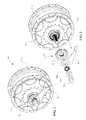
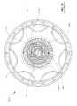
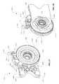
- FIG. 1is a perspective view of a ball planetary continuously variable transmission (CVT) having a skew-based control system.
- CVTcontinuously variable transmission
- FIG. 2is an exploded perspective view of the CVT of FIG. 1 .
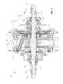
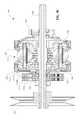
- FIG. 3is a cross-sectional view of the CVT of FIG. 1 .
- FIG. 4is a cross-sectional perspective view of certain components of the CVT of FIG. 1 .
- FIG. 5is an exploded, cross-sectional, perspective view of certain components of the CVT of FIG. 1 .
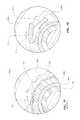
- FIG. 6is a perspective view of a first stator that can be used with the CVT of FIG. 1 .
- FIG. 7is another perspective view of the first stator of FIG. 6 .
- FIG. 8is a plan view of the first stator of FIG. 6 .
- FIG. 8Ais a plan view (detail view A) of one embodiment of a radially off-set slot that can be provided on the first stator of FIG. 6 .
- FIG. 9is a cross-sectional view of the first stator of FIG. 6 .
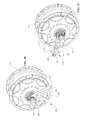
- FIG. 10is a perspective view of a second stator that can be used with the CVT of FIG. 1 .
- FIG. 11is another perspective view of the second stator of FIG. 10 .
- FIG. 12is a plan view of the second stator of FIG. 10 .
- FIG. 13is a cross-sectional view of the second stator of FIG. 10 .
- FIG. 14is a perspective view of a timing plate that can be used with the CVT of FIG. 1 .
- FIG. 15is a cross-sectional perspective view of the timing plate of FIG. 14 .
- FIG. 16is a Detail View B of the timing plate of FIG. 14 .
- FIG. 17is a perspective view of a stator driver assembly that can be used with the CVT of FIG. 1 .
- FIG. 18is an exploded perspective view of the stator driver assembly of FIG. 17 .
- FIG. 19is a perspective view of an embodiment of a stator driver assembly.
- FIG. 20is an exploded perspective view of the stator driver assembly of FIG. 19 .
- FIG. 21is a perspective view of another embodiment of a stator driver assembly.
- FIG. 22is an exploded perspective view of the stator driver assembly of FIG. 21 .
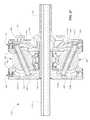
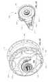
- FIG. 23is a cross-sectional view of an embodiment of a CVT having a skew-based control system.
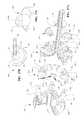
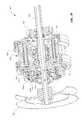
- FIG. 24is an exploded, cross-sectional perspective view of the CVT of FIG. 23 .
- FIG. 25is a perspective view of certain components of the CVT of FIG. 23 .
- FIG. 26is a cross-sectional perspective view of certain components of the CVT of FIG. 23 .
- FIG. 27Ais an exploded, cross-sectional perspective view of certain components of the CVT of FIG. 23 .
- FIG. 27Bis a plan view of an eccentric gear that can be used with the CVT of FIG. 23 .
- FIG. 27Cis a perspective view of a sliding block and the eccentric gear of FIG. 27 .
- FIG. 28is a perspective view of a shifting mechanism that can be used with the CVT of FIG. 1 or FIG. 23 .
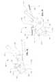
- FIG. 29is an exploded perspective view of the shifting mechanism of FIG. 28 .
- FIG. 30is a perspective view of an embodiment of a shifting mechanism that can be used with the CVT of FIG. 1 or 23 .
- FIG. 31is a perspective view of another embodiment of a shifting mechanism that can be used with the CVT of FIG. 1 or 23 .
- FIG. 32is a perspective view of yet another embodiment of a shifting mechanism that can be used with the CVT of FIG. 1 or 23 .
- FIG. 33is an exploded perspective view of the shifting mechanism of FIG. 32 .
- FIG. 34is a schematic illustration of an embodiment of a shifting mechanism that can be used with the CVT of FIG. 1 or 23 .
- FIG. 35is a schematic illustration of another embodiment of a shifting mechanism that can be used with the CVT of FIG. 1 or 23 .
- FIG. 36is a schematic illustration of a shifting mechanism and handle grip that can be used with the CVT of FIG. 1 or 23 .
- FIG. 37Ais a plan view illustration of a first position of the shifting mechanism of FIG. 36 .
- FIG. 37Bis a plan view illustration of a second position of the shifting mechanism of FIG. 36 .
- FIG. 38is a partial cross-section view of certain components of an embodiment of a CVT having a skew-based control system.
- FIG. 39is a plan view of a shifting mechanism that can be used with the CVT of FIG. 38 .
- FIG. 40is a schematic illustration of an embodiment of a shifting mechanism that can be used with a CVT having a skew-based control system.
- FIG. 41is a schematic illustration of another embodiment of a shifting mechanism that can be used with a CVT having a skew-based control system.
- FIG. 42is a schematic illustration of an embodiment of a shifting mechanism that can be used with a CVT having a skew-based control system.
- FIG. 43is a section A-A view of the shifting mechanism of FIG. 42 .
- FIG. 44is a schematic illustration of another embodiment of a shifting mechanism that can be used with a CVT having a skew-based control system.
- FIG. 45is a schematic illustration of a CVT having a skew-based control system and a fly-ball governor.
- FIG. 46Ais a schematic illustration of a CVT having a skew-based control system and a speed governor and a torque governor.
- FIG. 46Bis a schematic illustration of a CVT having a skew-based control system and a speed governor and a torque governor.
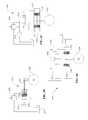
- FIG. 47is a schematic illustration of a hydraulic control system that can be used with a CVT having a skew-based control system.
- FIG. 48is a schematic of certain components of a bicycle employing a CVT having a skew-based control system.
- FIG. 49is a partial, cross-sectional perspective view of an embodiment of a CVT employing a skew-based control system.
- FIG. 50is a cross-sectional view of the CVT of FIG. 49 .
- FIG. 51is a partial, cross-sectional perspective view of another embodiment of a CVT employing a skew-based control system.
- FIG. 52is a cross-sectional view of the CVT of FIG. 51 .
- FIG. 53is a schematic view of an embodiment of a CVT having a skew-based control system and a planetary gear set.
- FIG. 54is a schematic view of an embodiment of a CVT having a skew-based control system and an actuator shaft.
- FIG. 55is a partial cross-sectional view of a CVT having a skew-based control system and an internal freewheel mechanism.
- FIG. 56is section view B-B of the CVT of FIG. 55 .
- FIG. 57is a detail view A of the CVT of FIG. 55 .
- FIG. 58is an alternative embodiment of a freewheel spring that can be used with the CVT of FIG. 55 .
- FIG. 59is a schematic illustration of a hydraulic control system that can be used with a CVT having a skew-based control system.
- FIG. 60is another schematic illustration of a hydraulic control system that can be used with a CVT having a skew-based control system.
- FIG. 61is yet another schematic illustration of a hydraulic control system that can be used with a CVT having a skew-based control system.
- FIG. 62is a perspective view of yet another embodiment of a shifting mechanism that can be used with the CVT of FIG. 1 , 23 , or 55 for example.
- FIG. 63is a perspective view of the shifting mechanism of FIG. 62 .
- FIG. 64is an exploded perspective view of the shifting mechanism of FIG. 62 .
- FIG. 65is a partial cross-section view of the shifting mechanism and CVT of FIG. 62 .
- FIG. 66is a partial cross-section perspective view of a traction planet carrier assembly that can be used with the CVT of FIG. 1 , 23 , 55 , or 62 for example.
- FIG. 67is a perspective view of yet another embodiment of a shifting mechanism that can be used with the CVT of FIG. 1 , 23 , or 55 for example.
- FIG. 68is another perspective view of the shifting mechanism of FIG. 67 .
- FIG. 69is an exploded, perspective view of the shifting mechanism of FIG. 67 .
- FIG. 70is a cross-sectioned plan view of the shifting mechanism of FIG. 67 .
- the terms “operationally connected,” “operationally coupled”, “operationally linked”, “operably connected”, “operably coupled”, “operably linked,” and like termsrefer to a relationship (mechanical, linkage, coupling, etc.) between elements whereby operation of one element results in a corresponding, following, or simultaneous operation or actuation of a second element. It is noted that in using said terms to describe inventive embodiments, specific structures or mechanisms that link or couple the elements are typically described. However, unless otherwise specifically stated, when one of said terms is used, the term indicates that the actual linkage or coupling may take a variety of forms, which in certain instances will be readily apparent to a person of ordinary skill in the relevant technology.
- radialis used here to indicate a direction or position that is perpendicular relative to a longitudinal axis of a transmission or variator.
- axialrefers to a direction or position along an axis that is parallel to a main or longitudinal axis of a transmission or variator.
- Traction drivesusually involve the transfer of power between two elements by shear forces in a thin fluid layer trapped between the elements.
- the fluids used in these applicationsusually exhibit traction coefficients greater than conventional mineral oils.
- the traction coefficient ( ⁇ )represents the maximum available traction forces which would be available at the interfaces of the contacting components and is a measure of the maximum available drive torque.
- friction drivesgenerally relate to transferring power between two elements by frictional forces between the elements.
- the CVTs described heremay operate in both tractive and frictional applications.
- the CVTcan operate at times as a friction drive and at other times as a traction drive, depending on the torque and speed conditions present during operation.
- the prime movercan be, for example, an electrical motor and/or an internal combustion engine.
- an accessoryincludes any machine or device that can be powered by a prime mover.
- said machine or devicecan be a power takeoff device (PTO), pump, compressor, generator, auxiliary electric motor, etc.
- Accessory devices configured to be driven by a prime movermay also include alternators, water pumps, power steering pumps, fuel pumps, oil pumps, air conditioning compressors, cooling fans, superchargers, turbochargers and any other device that is typically powered by an automobile engine.
- the speed of a prime movervaries as the speed or power requirements change; however, in many cases the accessories operate optimally at a given, substantially constant speed.
- Embodiments of the continuously variable transmissions disclosed herecan be used to control the speed of the power delivered to the accessories powered by a prime mover.
- inventive embodiments of the continuously variable transmissions disclosed herecan be used to decrease or increase speed and/or torque delivered to the accessories for achieving optimal system performance.
- inventive embodiments of the continuously variable transmissions disclosed herecan be used to increase speed to the accessories when the prime mover runs at low speed and to decrease speed to the accessories when the prime mover runs at high speed.
- the design and operation of accessoriescan be optimized by allowing the accessories to operate at one substantially favorable speed, or a more narrow speed range whereby the accessories need not be made larger than necessary to provide sufficient performance at an optimal speed or speed range.
- Embodiments of the invention disclosed hereare related to the control of a variator and/or a CVT using generally spherical planets each having a tiltable axis of rotation (sometimes referred to here as a “planet axis of rotation”) that can be adjusted to achieve a desired ratio of input speed to output speed during operation.
- adjustment of said axis of rotationinvolves angular misalignment of the planet axis in a first plane in order to achieve an angular adjustment of the planet axis of rotation in a second plane, thereby adjusting the speed ratio of the variator.
- the angular misalignment in the first planeis referred to here as “skew” or “skew angle”.
- a control systemcoordinates the use of a skew angle to generate forces between certain contacting components in the variator that will tilt the planet axis of rotation in the second plane.
- the tilting of the planet axis of rotationadjusts the speed ratio of the variator.
- Embodiments of skew control systems(sometimes referred to here as “skew based control systems”) and skew angle actuation devices for attaining a desired speed ratio of a variator will be discussed.
- FIG. 1shows a CVT 10 that can be used in many applications including, but not limited to, human powered vehicles (for example, bicycles), light electrical vehicles, hybrid human-, electric-, or internal combustion powered vehicles, industrial equipment, wind turbines, etc. Any technical application that requires modulation of mechanical power transfer between a power input and a power sink (for example, a load) can implement embodiments of the CVT 10 in its power train.
- human powered vehiclesfor example, bicycles
- a power sinkfor example, a load
- the CVT 10includes a housing 11 configured to structurally support and generally encloses components of the CVT 10 .
- the CVT 10can be provided with a shifting mechanism 12 configured to cooperate with, for example, a cable actuator of a bicycle (not shown).
- the CVT 10has a sprocket 14 configured to receive an input power.
- the shifting mechanism 12includes a pulley 16 coupled to a shift tube 18 .
- an input driver 20can be arranged coaxial with a main axle 22 .
- the input driver 20can be configured to receive an input power from, for example, the sprocket 14 or other suitable coupling.
- the input driver 20is coupled to a torsion plate 24 that is coupled to a first axial force generator assembly 26 .
- the axial force generator assembly 26is operably coupled to a first traction ring 28 .
- the first traction ring 28is configured to contact each of a plurality of traction planets 30 .
- Each traction planet 30is in contact with an idler 31 located radially inward of the traction planets 30 .
- a second traction ring 32is configured to contact each of the traction planets 30 .
- the second traction ring 32is coupled to a second axial force generator assembly 34 .
- the second axial force generator assembly 34can be substantially similar to the first axial force generator assembly 26 .
- the axial force generator assemblies 26 , 34can be substantially similar to the clamping force generator mechanisms generally described in Patent Cooperation Treaty Application PCT/US2007/023315, the entire disclosure of which is hereby incorporated herein by reference.
- the CVT 10can be provided with a set of nuts 33 and washers 35 A, 35 B to facilitate the coupling of the main axle 22 to, for example, a bicycle frame (not shown).
- the main axle 22can further be coupled to the bicycle frame via a reaction arm 37 .
- an input powercan be transferred to the input driver 20 via, for example, the sprocket 14 .
- the input driver 20can transfer power to the first axial force generator 26 via the torsion plate 24 .
- the first axial force generator 26can transfer power to the traction planets 30 via a traction or friction interface between the first traction ring 28 and the each of the traction planets 30 .
- the traction planets 30deliver the power to the housing 11 via the second traction ring 32 and the second axial force generator 34 .
- a shift in the ratio of input speed to output speed, and consequently, a shift in the ratio of input torque to output torqueis accomplished by tilting the rotational axis of the traction planets 30 . In one embodiment, the tilting of the rotational axes of the traction planets 30 is accomplished by rotating a first stator 36 with respect to a second stator 38 .
- each of the traction planets 30is provided with a planet axle 42 received in an inner bore.
- the traction planet 30is rotatable about the planet axle 42 .
- the planet axle 42is rotationally fixed relative to the traction planet 30 so that the planet axle 42 and the traction planet 30 rotate in unison.
- the CVT 10can be provided with a timing plate 40 operably coupled to one end of the planet axles 42 .
- the timing plate 40facilitates the general synchronization of the traction planet assemblies 30 .
- the CVT 10can be provided with a stator driver assembly 44 coupled to the shift tube 18 .
- the stator driver assembly 44is coupled to the first stator 36 .
- the stator driver assembly 44can facilitate a rotation of the first stator 36 about a longitudinal axis of the CVT 10 .
- the second stator 38is a substantially disc-shaped body 50 having a central bore 52 .
- the central bore 52facilitates the coupling of the second stator 38 to the main axle 22 .
- the disc-shaped body 50can be provided with a plurality of radially off-set curved guide slots 54 arranged angularly about the central bore 52 .
- Each radially off-set guide slot 54is sized to accommodate the coupling of the second stator 38 to the planet axle 42 .
- the radially off-set guide slots 54are angularly offset from a radial construction line 56 when viewed in the plane of the page of FIG. 8 . The angular offset can be approximated by an angle 58 .
- the angle 58is formed between the radial construction line 56 and a construction line 60 .
- the construction line 60substantially bisects the guide slot 54 when viewed in the plane of the page of FIG. 8 .
- the angle 58is between 3 degrees and 45 degrees.
- a low angle 58would provide faster shift rates in a given application but stator clocking angle (beta) must be controlled over a very small range.
- a high angle 58would provide slower shift rates in a given application but stator clocking angle (beta) would be controlled over a larger range.
- a low angle 58is highly responsive in transmission ratio change but potentially more difficult to control or stabilize, while a high angle can be less responsive in transmission ratio change but easy to control by comparison.
- the angle 58can be, for example, 10 degrees. In other embodiments, where it is desirable to have slower speed, precise control of transmission ratio, the angle 58 can be about 30 degrees. However, the said values of the angle 58 are provided as an illustrative example, and the angle 58 can be varied in any manner a designer desires. In some embodiments, the angle 58 can be any angle in the range of 10 to 25 degrees including any angle in between or fractions thereof. For example, the angle can be 10, 11, 12, 13, 14, 15, 16, 17, 18, 19, 20, 21, 22, 23, 24, 25, or any portion thereof. In other embodiments, the angle 58 can be 20 degrees.
- the radially off-set guide slots 54can be arranged so that the construction line 60 is linearly offset from a construction line 61 by a distance 62 .
- the construction line 61is parallel to the construction line 60 and intersects the center of the disc-shaped body 50 .
- the second stator 38can be provided with a guide slot 53 .
- the guide slot 53can be substantially similar to the guide slot 54 .
- the guide slot 53can have a substantially curved profile when viewed in the plane of the page of FIG. 8A .
- the curvature of the guide slot 53can be generally defined by a construction line 57 .
- a construction line 57can be shown tangent to the construction line 60 .
- the construction line 57is a constant radius curve.
- the construction line 57can be a non-constant radius curve.
- the curvature of the construction line 57 , and consequently the curvature of the guide slot 53can be configured to provide the desired control stability and response of the CVT 10 .
- the first stator 36is a substantially disc-shaped body 70 having a central bore 72 .
- the central bore 72can be configured to couple to the stator driver assembly 44 .
- the disc-shaped body 70can be provided with a plurality of curved guide slots 74 arranged angularly about the central bore 72 .
- the guide slots 74are aligned with a radial construction line 76 when viewed in the plane of the page of FIG. 12 .
- the first stator 36can be provided with guide slots 74 that are angularly offset in a similar configuration as the guide slots 54 .
- the first traction ring 28can carry less torque than the traction ring 32 during operation of the CVT 10 . It may be desirable in some applications to place the first stator 36 in proximity to the first traction ring 28 so that the first stator 36 operates with lower torque than, for example, the second stator 38 .
- the timing plate 40is a substantially disc-shaped body 80 having a central bore 82 .
- the disc-shaped body 80is provided with a plurality of helical grooves 84 formed on a first face.
- the helical grooves 84are configured to operably couple to the planet axles 42 .
- the helical grooves 84are angled with respect to the guide slots 74 .
- the angle of the helical grooves 84 with respect to the guide slots 74is about 40 degrees when viewed down the longitudinal axis of the CVT 10 .
- the timing plateis provided with tabs 86 .
- the tabs 86facilitate the coupling of the timing plate 40 to, for example, the stator driver assembly 44 .
- the timing plate 40is adapted to be rotationally unconstrained to the stator driver assembly 44 .
- the stator driver assembly 44includes a compound planetary gear set having a sun gear 90 arranged to couple to the shift tube 18 .
- the stator driver assembly 44includes a number of planet gears 92 coupled to first and second ring gears 94 , 96 .
- the first ring gear 94can couple to the main shaft 22 while the second ring gear 96 can couple to the first stator 36 .
- the stator driver assembly 44includes a carrier 98 ( FIG. 5 ).
- the carrier 98can couple to the timing plate 40 .
- the carrier 98can couple to the planetary gears 92 .
- the number of teeth and pitch of the sun gear 90 , the planet gears 92 , and the first and second ring gears 94 , 96can be sized to provide the desired rotation of the first stator 36 .
- the reduction provided by the stator driver assembly 44is in the range of about 0.019 rotations of the ring gear 96 to one rotation of the sun gear 90 .
- the ration of the carrier 98is about 0.68 rotations to one rotation of the sun gear 90 .
- a stator driver assembly 100can include a compound planocentric gear set having a fixed ring 102 , an output ring 104 , and a compound orbital planet gear 106 .
- the compound orbital planet gear 106can be coupled to an eccentric driver 108 .
- the eccentric driver 108can be provided with an eccentric lobe surface 109 that is configured to engage an inner bore 110 of the compound orbital planet gear 106 .
- the eccentric driver 108can be rotated by the shift tube 18 , for example.
- the compound orbital planet gear 106is provided with a first gear 112 and a second gear 114 .
- the first gear 112couples to the fixed ring 102 .
- the second gear 114couples to the output ring 104 .
- the stator driver assembly 100can be configured to provide a ratio of 0.01 to 0.05 turns of the orbital planet gear 106 to about one turn of the eccentric driver 108 .
- the ratio rangeis such that a positive rotation of the eccentric driver 108 can result in either a clockwise or a counterclockwise rotation of the output ring gear 104 .
- the ratio rangecan be 0.01 to 0.05 turns of the output ring gear 104 to one turn of the eccentric driver 108 .
- a stator driver assembly 120can include a planocentric gear set 120 having a fixed carrier 122 coupled to first and second orbital planet gears 124 , 126 .
- the first and second orbital planet gears 124 , 126couple to an output ring 128 .
- the first and second orbital planet gears 124 , 126can be coupled to an eccentric driver 130 .
- the eccentric driver 130can be coupled to the shift tube 18 , for example.
- the eccentric driver 130is provided with eccentric lobe surfaces 131 A, 131 B that are configured to engage first and second inner bores 132 A, 132 B of the first and second orbital planet gears 124 , 126 , respectively.
- the fixed carrier 122can be provided with a number of pins 134 to facilitate the coupling of the fixed carrier 122 to a number of holes 136 A, 136 B of the first and second orbital planet gears 124 , 126 , respectively.
- the holes 136 A, 136 Bhave a larger diameter than the pins 134 to provide a small degree of freedom to the first and second orbital planet gears 124 , 126 .
- the degree of freedomallows the first and second orbital gears 124 , 126 to orbit about the longitudinal axis while substantially preventing rotation of the first and second orbital planet gears 124 , 126 about the longitudinal axis.
- the first and second orbital planet gears 124 , 126share the torque transfer to the output ring 128 .
- the eccentric lobe surfaces 131can be configured to prevent backlash between the first and second orbital planet gears 124 , 126 .
- the ratio range of the stator driver assembly 120is about 0.03 rotations of the output ring 128 to one rotation of the eccentric driver 130 .
- a CVT 140can include a number of traction planet assemblies 142 , for example six traction planet assemblies 142 , arranged angularly about a main axle 144 .
- the main axle 144generally defines a longitudinal axis of the CVT 140 .
- the traction planet assemblies 142are in contact with a traction sun assembly 146 .
- the traction sun assembly 146is located radially inward of the traction planet assemblies 142 .
- the traction sun assembly 146is coaxial with, the main axle 144 .
- the CVT 140includes first and second traction rings 148 , 150 , in contact with each of the traction planet assemblies 142 .
- the first traction ring 148is coupled to a first axial force generator assembly 152 .
- the first axial force generator assembly 152is coupled to an input driver ring 154 .
- the input driver ring 154is configured to receive an input power.
- the second traction ring 150is coupled to a second axial force generator assembly 156 .
- the second axial force generator 156is configured to transfer a power out of the CVT 140 .
- the CVT 140includes a first stator 160 coupled to a reaction plate 162 .
- the CVT 140includes a second stator 164 operably coupled to the first stator 160 .
- the first and second stators 160 , 164 and the reaction plate 162are coaxial with the main axle 144 .
- the first stator 160 and the reaction plate 162are substantially non-rotatable about the main axle 144 .
- the second stator 164can be configured to rotate about the main axle 144 relative to the first stator 160 .
- the first stator 160can be provided with a number of guide slots 161 .
- the guide slots 161can be arranged on the first stator 160 in a substantially similar manner as the curved guide slots 74 ( FIG. 12 ) are arranged on the stator 36 .
- the second stator 164can be provided with a number of guide slots 165 .
- the guide slots 165can be arranged substantially similar to the curved guide slots 54 ( FIG. 8 ) on the stator 38 .
- Each of the traction planet assemblies 142couples to the guide slots 161 and 165 .
- the traction planet assemblies 142are provided with a planet axle support 143 .
- the planet axle supports 143have a top-hat cross-section when viewed in the plane of the page of FIG. 23 .
- the planet axle supports 143can be formed as an integral component as shown in FIG. 23 .
- the planet axle supports 143can be divided into two components: a cap 143 A and a ring 143 B, where the ring 143 B is coupled to the reaction plate 162 and the cap 143 A is coupled to the second stator 164 , for example.
- the ring 143 Bcan be an o-ring (not shown), in which case the planet axle is adapted to receive the o-ring.
- a rotation of the second stator 164 with respect to the first stator 160induces a skew condition on the traction planet assemblies 142 to thereby facilitate a change in the speed ratio of the CVT 140 .
- the first and second stators 160 , 164are coupled to each of the traction planet assemblies 142 .
- the CVT 140includes a stator driver 166 coaxial with, and rotatable about the main axle 144 .
- the stator driver 166can be configured to operably couple to, for example, a cable actuator via a pulley or some other suitable coupling (not shown) for facilitating a rotation of the stator driver 166 about the main axle 144 .
- the stator driver 166couples to a set of eccentric gears 168 .
- the eccentric gear 168can be provided with gear teeth (not shown) to interface with a gear ring 169 of the stator driver 166 .
- the eccentric gears 168couple to the second stator 164 and the reaction plate 162 .
- Each of the eccentric gears 168has a cam lobe 170 extending from a reaction lobe 172 .
- the cam lobe 170can be surrounded by an anti-friction sleeve or bushing (not shown) to reduce friction between the eccentric gear 168 and the reaction plate 162 .
- the cam lobe 170 and the reaction lobe 172attach to a gear ring 174 .
- the rotational center 171 of the cam lobe 170is offset from the rotational center 173 of the reaction lobe 172 by a distance D when viewed in the plane of FIG. 27B . In one embodiment, the distance D is in the range of about 0.5 mm to about 5 mm.
- the distance Dis about 3.1 mm.
- the cam lobes 170couple to a number of guide slots 176 provided on the reaction plate 162 .
- the reaction lobes 172slidingly couple to a number of guide bores 178 provided on the second stator 164 .
- the CVT 140can have one or more gears 168 .
- the CVT 140has three eccentric gears 168 .
- the first stator 160is provided with a number of fingers 180 .
- Each finger 180is provided with a reaction member 182 extending axially from the finger 180 .
- the reaction member 182is configured to couple to the reaction plate 162 .
- the reaction members 182can couple to the reaction plate 162 through insertion into a set of holes 184 with, for example, a press-fit.
- the reaction members 182extend axially past the reaction plate 162 and come into contact (under certain operating conditions of the CVT 140 ) with a number of shoulders 186 formed on the second stator 164 .
- the reaction member 162is provided with a number of clearance slots 187 .
- the clearance slots 187are generally aligned with the guide slots 161 and 165 and are sized to accommodate the traction planet assemblies 142 .
- the first stator 160can be provided with a number of splines 189 that are configured to engage a number of splines 190 formed on the reaction plate 162 .
- the stator driver 166can be rotated to thereby rotate the eccentric gears 168 . Since the rotational center 171 of the cam lobe 170 is offset from the rotational center 173 of the reaction lobe 172 , a rotation of the eccentric gears 168 tends to rotate the second stator 164 with respect to the first stator 160 .
- the offset Dprovides a moment arm that allows a force to be transferred from the second stator 164 to the reaction plate 162 .
- a torque applied to the second stator 164 during operation of the CVT 140can be reacted by the reaction plate 162 . Therefore, the amount of torque required to rotate the stator driver 166 is low.
- the guide slots 176 of the reaction plate 162can be configured to couple to a sliding block 206 .
- the sliding block 206can couple to the cam lobe 170 .
- the sliding block 206is made from a low friction material.
- the sliding block 206can have flat sides adapted to slidingly engage the guide slot 176 . The flat sides facilitate the reduction of pressure on reaction plate 162 , which also lowers friction.
- a shifting mechanism 250can be configured to cooperate with the CVT 10 , the CVT 140 , or any other comparable CVT having a skew-based control system.
- the shifting mechanism 250includes a reaction arm 252 coupled to, for example, the main axle 22 .
- the reaction arm 252is substantially non-rotatable with respect to the main axle 22 .
- the reaction arm 252is provided with a splined bore 253 configured to engage the main axle 22 .
- the shifting mechanism 250is provided with a shift arm 254 coupled to, for example, the shift tube 18 .
- the shift arm 254is provided with a splined bore 255 configured to engage the shift tube 18 .
- the shift arm 254is configured to rotate with respect to the reaction arm 252 .
- the shifting mechanism 250is configured to couple to a cable 256 .
- the cable 256can be of any type well-known in the bicycle industry.
- the cable 256can be provided with a cable end 258 .
- the cable end 258is substantially cylindrical. In one embodiment, the cable end 258 is coupled to a guide slot 260 provided on the reaction arm 252 .
- the cable end 258is coupled to a guide slot 261 provided on the shift arm 254 .
- the cable end 258is adapted to slide in the guide slots 260 , 261 .
- the cable end 258can be coupled to a spring 262 .
- the spring 262couples to the reaction arm 252 to thereby bias the cable end 258 toward on end of the guide slot 260 .
- a movement of the cable 256tends to translate the cable end 258 in the guide slots 260 , 261 , which thereby rotates the shift arm 254 with respect to the reaction arm 252 .
- a rotation of the shift arm 254thereby rotates, for example, the shift tube 18 , which tends to shift the transmission ratio of the CVT 10 .
- a shifting mechanism 280can be configured to cooperate with the CVT 10 , the CVT 140 , or any other comparable CVT having a skew-based control system.
- the shifting mechanism 280includes a reaction arm 282 coupled to, for example, the main axle 22 .
- the reaction arm 282is substantially non-rotatable with respect to the main axle 22 .
- the reaction arm 282is provided with a hole 284 to facilitate the coupling of the reaction arm to a standard cable (not shown).
- the shifting mechanism 280is provided with a rocker arm 286 .
- the rocker arm 286can be configured to couple to a cable (not shown) to facilitate a rotation of the rocker arm 286 with respect to the reaction arm 282 .
- the rocker arm 286is provided with a D-shaped pivot 288 that is adapted to transfer a torque from the rocker arm 286 to a shift tube driver (not shown).
- the shift tube drivercan be a gear adapted to couple to, for example, the shift tube 18 .
- the shift tube drivercan be a pulley adapted to couple to the shift tube 18 .
- the shift tube drivercan be a belt, or other suitable coupling, adapted to transfer a torque from the rocker arm 286 to the shift tube 18 .
- a shifting mechanism 290can be configured to cooperate with the CVT 10 , the CVT 140 , or any other comparable CVT having a skew-based control system.
- the shifting mechanism 290can be provided with an input gear 292 adapted to couple to a standard cable (not shown) via, for example, a pulley or some other suitable coupling.
- the shifting mechanism 290is provided with a transfer gear 294 coupled to the input gear 292 .
- the input gear 292is provided with a bore 296 .
- the transfer gear 294is provided with a bore 298 .
- the bores 296 , 298are adapted to attach to a fixed member such as a bicycle frame or a reaction arm such as the reaction arm 282 (not shown in FIG. 29 ).
- the transfer gear 294is provided with an eccentric guide bore 300 .
- the shifting mechanism 290is provided with a shift arm 302 operably coupled to the eccentric guide bore 300 via, for example, a dowel (not shown).
- the shift arm 302couples to, for example, the shift tube 18 .
- a shift in a transmission ratio during operation of, for example, the CVT 10can be achieved by rotating the input gear 292 to thereby rotate the transfer gear 294 about the bore 298 .
- a rotation of the transfer gear 294tends to rotate the shift arm 302 via the eccentric guide bore 300 .
- a shifting mechanism 310can include a substantially non-rotatable reaction arm 311 .
- the shifting mechanism 310is provided with a pulley 312 coupled to, for example, a shift tube 18 via a splined bore 313 .
- the pulley 312is provided with a cable end attachment interface 314 .
- the pulley 312can have an eccentric shape.
- the pulley 312can be a circular shape.
- the shape of the pulley 312is configured to provide a desired ratio between rotations of the shift tube 18 and the resulting transmission ratio of the CVT 10 .
- the reaction arm 311is provided with a cable housing interface 315 that is configured to cooperate with a standard cable and cable housing (not shown).
- the reaction arm 311is provided with a splined bore 316 .
- the shifting mechanism 310is provided with an indexing washer 317 that is configured to couple to the splined bore 316 .
- the indexing washer 317has a number of indexing markings 318 .
- the indexing washer 317can have an inner bore 319 configured to mate with, for example, the main axle 22 , in such a way as to prevent rotation of the indexing washer 317 , and consequently the reaction arm 311 , with respect to the main axle 22 .
- the indexing washer 317can be provided with a slot formed on the inner bore.
- the slotcan receive a frictional spring type element (not shown) that can be made of wire or plastic to employ a slight interference or frictional fit onto the main axle 22 .
- the indexing washer 317can aid in the retention of the reaction arm 311 onto the main shaft 22 such that it will not accidentally fall off while trying to fit the CVT 10 into a bike frame.
- the shifting mechanism 310provides advantages for removal of a wheel (not shown) equipped with the CVT 10 , for example, from a bicycle as a complete assembly without any tools, thus allowing disconnection between the cable that is attached to the bike frame and the CVT 10 .
- the indexing markings 318can be used to maintain the orientation upon removal and re-installation of the wheel.
- a shifting mechanism 320can include a reaction arm 322 coupled to, for example, a bicycle frame 324 .
- the shifting mechanism 320is provided with a shift arm 326 .
- the shift arm 326can be coupled to, for example, the shift tube 18 .
- the shift arm 326is coupled to a first lever 328 at a first pivot 330 .
- the first lever 328is coupled to a second lever 332 at a second pivot 334 .
- the second lever 332is coupled to the reaction arm 322 at a third pivot 336 .
- the shifting mechanism 320is provided with a spring 338 coupled to the second pivot 334 and the reaction arm 322 .
- first, second, and third pivots 330 , 334 , 336are common fasteners configured to provide relative rotation between the first and second levers 328 , 332 .
- the shifting mechanism 320can be coupled to a standard cable (not shown) at the pivot 334 .
- the standard cablecan be configured to translate the pivot 334 in the rightward and leftward direction (in reference to plane of FIG. 34 ). The translation of the pivot 334 tends to rotate the shift arm 326 .
- a shifting mechanism 350can be provided with a reaction arm 352 coupled to, for example, a bicycle frame 354 .
- the reaction arm 352can be adapted to couple to a cable 355 and a cable sleeve 356 .
- the shifting mechanism 350has a shift arm 358 coupled to, for example, the shift tube 18 .
- the shifting mechanism 350has a lever 360 coupled to the shift arm 358 at a first pivot 362 .
- the lever 360is coupled to the cable 355 at a second pivot 364 .
- the second pivot 364is located on one end of the lever 360 at a distal location from the first pivot 362 .
- the shifting mechanism 350is provided with a linkage 366 coupled to the reaction arm 352 at a pivot 368 .
- the linkage 366is coupled to the lever 360 at a pivot 370 .
- the pivot 370is located between the first and second pivots 362 , 364 .
- the cable 355can be pulled to thereby move the lever 360 .
- the lever 360tends to rotate about the pivot 370 to facilitate a rotation of the shift arm 358 .
- a shifting mechanism 400can couple to a handle grip 402 via a cable 404 .
- the shifting mechanism 400includes a pulley 406 .
- the pulley 406can have a splined inner bore adapted to couple to a reaction member 408 .
- the pulley 406can operably couple to the shift tube 18 , for example.
- the reaction member 408can be provided with a pocket 410 .
- the pocket 410is adapted to support a spring 412 .
- the spring 412is coupled to a roller 414 . The spring 412 tends to press the roller 414 towards the splined inner bore of the pulley 406 .
- the roller 414applies a holding force on the pulley 406 which facilitates the engagement of the splined inner bore of the pulley 406 to the splined circumference of the reaction member 408 at, for example, a location 416 .
- the shifting mechanism 400is positioned in proximity to the CVT 10 , for example. In some embodiments, the shifting mechanism 400 can be located within, or in proximity to, the handle grip 402 .
- a control forceis applied to the cable 404 to facilitate a rotation of the pulley 406 .
- the control forceinduces a tension in the cable 404 , which tends to displace the pulley 406 in the direction of the control force, for example the pulley 406 displaces in a rightward direction when viewed in the plane of the page of FIG. 37A .
- FIG. 37Bdepicts a position of the pulley 406 in the presence of cable tension in comparison to a non-tensioned position 406 ′ (depicted in dashed lines).
- the pulley 406 and the reaction member 408do not contact at the location 416 in the presence of cable tension which enables the pulley 406 to rotate relative to the reaction member 408 .
- the spring 412urges the pulley 406 in the leftward direction (in reference to FIG. 40A ), which engages the pulley 406 and the reaction member 408 at the location 416 .
- a CVT 450can be substantially similar to the CVT 10 .
- the CVT 450has a plurality of traction planet assemblies 452 coupled to a first stator 454 and a second stator 456 .
- the traction planet assemblies 452are configured to contact an idler assembly 458 .
- the second stator 456is coupled to a shifting mechanism 460 .
- the shifting mechanism 460includes a roller 462 in contact with the second stator 456 and a guide member 464 .
- the guide member 464can be configured to rotate about a main axle 465 .
- the guide member 464is coupled to a shift tube 466 .
- the shift tube 466can be substantially similar to the shift tube 18 .
- the shifting mechanism 460can include a reaction arm 468 in contact with the roller 462 .
- the reaction arm 468can rotate about a pivot 467 .
- the pivot 467can be coupled to a grounded arm 469 .
- the grounded arm 469can attach to the main axle 465 .
- the reaction arm 468couples to the first stator 454 at an end 470 .
- the end 470can be pinned to the first stator 454 through a suitable coupling means.
- the coupling between the first stator 454 and the end 470involves a rod (not shown) arranged between the traction planet assemblies 452 .
- the rodcan be positioned axially to facilitate the coupling of the first stator 454 to the end 470 .
- the reaction arm 468can be provided with at least one surface 471 adapted to radially guide the roller 462 .
- the second stator 456reacts torque from the traction planet assemblies 452 .
- the torquecan be transferred from the second stator 456 via the roller 462 to the surface 471 of the reaction arm 468 .
- a relative rotation between the first and second stators 454 , 456can be facilitated by a rotation of the guide member 464 with, for example, a shift arm 472 .
- the shift arm 472can be substantially similar to the shift arm 254 , the shift arm 302 , the shift arm 326 , or any other suitable shift arm.
- the assembly 458can include a first rolling element 480 and a second rolling element 481 , both in contact with each of the traction planet assemblies 452 .
- the first and second rolling elements 480 , 481are supported with bearings 482 , 483 on a support tube 484 .
- the support tube 484is substantially fixed from axial movement.
- the bearings 482 , 483are directly coupled to the main axle 22 .
- the idler assembly 458can float with respect to the main axle 22 .
- a shifting mechanism 550can include a stator 552 that is substantially similar to the stator 38 .
- the shifting mechanism 550is provided with a shift tube 554 that can be substantially similar to the shift tube 18 .
- the shift tube 554is arranged coaxial with the stator 552 .
- the shift tube 554can be configured to couple to a push link 556 .
- An interface 555 between the shift tube 554 and the push link 556can be a pinned joint or other suitable coupling.
- the shifting mechanism 550can be provided with a reaction arm 558 that is adapted to be substantially non-rotatable.
- the reaction arm 558is coupled to the stator 552 via a spring 560 .
- the shifting mechanism 550is provided with a linkage 562 coupled to the push link 556 on a first end and coupled to the reaction arm 558 on a second end. Each end of the linkage 562 is configured to pivot.
- the shifting mechanism 550can be provided with a linkage 564 coupled at a first end to the push link 556 and coupled at a second end to the stator 552 . Each end of the linkage 564 is configured to pivot.
- the stator 552can be rotated to facilitate a change in a transmission ratio.
- the shift tube 554can be rotated by a standard cable (not shown), which tends to move the push link 556 .
- the movement of the push link 556tends to displace the linkage 564 with respect to the linkage 562 in a scissor-like motion to thereby rotate the stator 552 .
- a rotation of the stator 552can also be facilitated by a change in a torque applied to the stator 552 during operation of a CVT.
- the spring 560couples the reaction arm 558 to the stator 552 , therefore a change in torque applied to the stator 552 results in a displacement of the spring 560 .
- a change in the displacement of the spring 560corresponds to a rotation of the stator 552 . Consequently, a desired operating torque for a CVT can be prescribed for a desired speed ratio by appropriately sizing and preloading the spring 560 .
- a shifting mechanism 600can include a stator 602 that is substantially similar to the stator 38 .
- the shifting mechanism 600can include a driver 604 adapted to cooperate with, for example, a pulley (not shown) or other suitable actuator.
- the driver 604can be provided with gear teeth to engage a driven gear 606 .
- the driven gear 606has a slot 608 that is adapted to engage a pin 610 .
- the pin 610is attached to the stator 602 .
- a rotation of the driver 604tends to rotate the driven gear 606 .
- the rotation of the driven gear 606urges the pin 610 to rotate the stator 602 . Consequently, the pin 610 slides in the slot 608 .
- a CVT 620can be provided with a shifting mechanism 621 .
- the CVT 620can be substantially similar to the CVT 10 .
- the shifting mechanism 621can have a shift tube 622 configured to carry a number of rollers 624 .
- the shift tube 622is adapted to translate axially.
- the rollers 624engage a first helical groove 626 formed in a main shaft 628 .
- the rollers 624engage a second helical groove 630 formed in a first stator 632 .
- the first and second helical grooves 626 , 630are high lead.
- the first and second helical grooves 626 , 630can be nearly axial grooves.
- the first stator 632can be substantially similar to the stator 38 .
- An axial translation of the shift tube 622tends to move the rollers 624 in the helical grooves to thereby rotate the first stator 632 with respect to a second stator 634 .
- the first and second helical grooves 626 , 630have different leads so that at least a portion of the torque applied to the first stator 632 can be transferred to the main shaft 628 during operation of the CVT 620 .
- the main shaft 628 and the first and second stators 632 , 634are adapted to receive a power input and rotate about a longitudinal axis 636 .
- the shift tube 622can be suitably coupled to an actuator (not shown) to facilitate the axial translation of the shift tube 622 along the main shaft 628 .
- the CVT 620can be provided with a shift tube 640 .
- the shift tube 640can have a slot 642 adapted to couple to the rollers 624 .
- the shift tube 640can be configured to rotate about the main shaft 628 .
- the shift tube 640can be coupled to a suitable actuator to facilitate a rotation of the shift tube 640 .
- the rotation of the shift tube 640tends to rotate the roller 624 to thereby facilitate a relative rotation between stators 634 , 632 .
- a CVT 660includes, among other things, first and second traction rings 661 , 662 and an idler 663 in contact with a group of traction planet assemblies 664 .
- the CVT 660can be substantially similar to the CVT 10 .
- the CVT 660can be provided with a first stator 666 and a second stator 668 operably coupled to the traction planet assemblies 664 .
- the first and second stators 666 , 668can be configured substantially similar to the stators 36 , 38 .
- the CVT 660can be provided with a well-known fly-ball governor.
- the fly-ball governoris depicted as a ball 670 .
- the fly-ball governorcan include a spring adjustment and appropriate bearings (not shown).
- the fly-ball governorcan include the ball 670 in contact with a stator driver 672 and a stator member 674 .
- the stators 666 , 668are adapted to receive an input power and rotate about the longitudinal axis LA.
- the ball 670tends to radially displace proportional to the speed of the first and second stators 666 , 668 .
- a radial displacement of the ball 670can correspond to an axial translation of the stator driver 672 .
- the stator driver 672can have a threaded interface with the second stator 668 .
- the fly-ball governoris configured to cooperate with the first traction ring 661 so that a change in the speed of the first traction ring 661 tends to rotate the first stator 666 with respect to the second stator 668 .
- the first traction ring 661can be configured to receive an input power
- the second traction ring 662can be configured to transfer an output power out of the CVT 660 .
- a CVT 700includes, among other things, first and second traction rings 701 , 702 and an idler 703 in contact with a group of traction planet assemblies 704 .
- the traction planet assemblies 704can be operably coupled to first and second stators 706 , 708 .
- the first stator 706can be coupled to a fly-ball governor 710 .
- the fly-ball governor 710can be configured to rotate the first stator 706 corresponding to a change in the rotational speed.
- the second stator 708can be coupled to a spring member 712 .
- the first and second stators 706 , 708can be adapted to receive an input power.
- the first traction ring 701can be adapted to receive an input power.
- a CVT 720can be configured to include a fly-ball governor 722 coupled to a first traction ring 721 and a first stator 723 .
- the first traction ring 721 and the first stator 723can be substantially similar to the first traction ring 701 and the first stator 706 , respectively.
- the spring 712can react a torque transferred from the second stator 708 .
- the spring 712can displace relative to the magnitude of the torque.
- the second stator 708tends to rotate with respect to the first stator 706 corresponding to the displacement of the spring 712 .
- a desired operating torque for a CVTcan be prescribed by appropriately sizing and preloading the spring 712 .
- the combination of the fly-ball governor 710 or 722 with the spring 712provides both speed control and torque control for the CVT 700 or 720 , which is desirable in mobile ground vehicles, for example.
- a control system 750can be configured to cooperate with, for example, CVT 10 or any of the CVT embodiments disclosed here.
- the control system 750can include a pump 752 in fluid communication with a flow control valve 754 .
- the flow control valve 754can have a coupling 756 adapted to rotate, for example, a stator 758 .
- the flow control valve 754can be in fluid communication with an orifice 760 .
- the orifice 760directs a fluid to a fluid reservoir 762 .
- the fluid reservoir 762can supply the fluid to the pump 752 .
- the orifice 760is a fixed orifice.
- the orifice 760is a variable orifice.
- a transmission ratiocan be adjusted and maintained using the flow control valve 754 .
- a torque applied to the stator 758can be reacted by the flow control valve 754 via the coupling 756 .
- the control system 750can be configured to function as a torque limiter for the CVT 10 or any similar CVT having a skew-based control system.
- a bicycle 800can include the CVT 10 , for example, coupled to a wheel 801 with spokes 802 .
- the CVT 10can be provided with a shift arm 804 that is adapted to operably couple to, for example, a shift tube 18 .
- the bicycle 800can include a drive chain 806 coupled to a well-known chain tensioner 808 .
- the chain tensioner 808can be coupled to the shift arm 804 via a turn buckle 810 , for example.
- a userapplies a force to the pedals 812 resulting in an oscillatory torque transmission to the chain 806 .
- the oscillatory torquetends to tension and un-tension the chain 806 , which causes the chain 806 to displace and move the chain tensioner 808 .
- the movement of the chain tension 808tends to rotate the shift arm 804 .
- a CVT 900can have a number of traction planet assemblies 902 arranged radially about a main axle 904 .
- the CVT 900can be substantially similar to the CVT 140 .
- the CVT 900is adapted to receive an input power with, for example, a pulley 906 or other suitable coupling.
- the pulley 906can be coupled to the main axle 904 .
- the CVT 900can have an output gear 905 configured to transfer power from a traction ring 907 .
- the traction ring 907can be in contact with each of the traction planet assemblies 902 .
- the main axle 904is coupled to a first stator 908 and a second stator 910 .
- the first and second stators 908 , 910can be configured to support each of the traction planet assemblies 902 .
- the first and second stators 908 , 910are adapted to transfer the input power to the traction planet assemblies 902 .
- the first and second stators 908 , 910are configured to rotate with the main axle 904 .
- the first and second stators 908 , 910are adapted to rotate with respect to each other to induce a skew condition on the traction planet assemblies 902 .
- the skew conditionfacilitates a change in transmission ratio of the CVT 900 .
- the CVT 900has a number of eccentric gears 912 coupled to the first stator 908 .
- the eccentric gears 912can be substantially similar to the eccentric gears 168 .
- the eccentric gears 912couple to a shift tube 914 .
- the shift tube 914can couple to a compound planetary gear set having a first ring gear 916 and a second ring gear 917 , each ring gear 916 , 917 coupled to a number of planet gears 918 .
- the planet gears 918 A, 918 Bshare a common axle and are free to rotate with respect to each other.
- the shift tube 914can couple to a first sun gear 920 .
- a second sun gear 922can couple to the main axle 904 .
- the first ring gear 916is coupled to, for example, a non-rotatable housing (not shown).
- the second ring gear 917can be coupled to a suitable actuator such as a motor (not shown).
- a relative rotation between the first ring gear 916 and the second ring gear 917tends to facilitate a relative rotation between the first stator 908 and the second stator 910 .
- a CVT 1000can be substantially similar to the CVT 900 .
- the CVT 1000is configured to receive an input power from, for example, the pulley 906 .
- the pulley 906can be coupled to a main shaft 1002 .
- the first traction ring 907is substantially non-rotatable about the main shaft 1002 .
- the CVT 1000can have an output gear 1004 configured to receive power from a second traction ring 1006 .
- the output gear 1004is coaxial with a shift tube 1008 .
- the shift tube 1008is coupled to the first stator 908 .
- the shift tube 1008is coupled to the first sun gear 920 .
- the CVT 1000can have a spring 1010 coupled to the first stator 908 .
- a change in the transmission ratiois facilitated by a relative rotation between the first and second stators 908 , 910 .
- the first stator 908can be rotated with respect to the second stator 910 via a rotation of the shift tube 1008 .
- the shift tube 1008is rotated during operation in a substantially similar manner as the shift tube 914 via the sun gear 920 .
- a CVT 1050can be substantially similar to the CVT 1000 .
- the CVT 1050includes a planetary gear set 1052 coupled to a first stator 1054 with, for example, a chain or a belt 1056 .
- the planetary gear set 1052can couple to a second stator 1058 with, for example, a chain or a belt 1060 .
- the planetary gear set 1052includes a first ring gear 1062 coupled to a number of planet gears 1064 .
- the planet gears 1064couple to a first sun gear 1066 .
- the first sun gear 1066is substantially non-rotatable.
- the planetary gear set 1052includes a second ring gear 1068 coupled to a number of planet gears 1070 .
- the planet gears 1070couple to a second sun gear 1072 .
- the second sun gear 1072can be coupled to a suitable actuator (not shown).
- the actuatorcan be adapted to rotate the second sun gear 1072 during operation of the CVT 1050 .
- the planet gears 1064 and 1070can be coupled to a carrier 1074 .
- the carrier 1074can be adapted to receive an input power 1076 (depicted as an arrow in FIG. 53 ).
- a CVT 1100can be substantially similar to the CVT 1000 .
- the CVT 1100includes a first stator 1102 and a second stator 1104 .
- the first stator 1102can be coupled to an input shaft 1106 with a chain or belt 1108 .
- the input shaft 1106is adapted to receive an input power 1110 (depicted as an arrow in FIG. 54 ).
- the second stator 1104is configured to couple to a shift tube 1112 with a chain or a belt 1114 .
- the shift tube 1112is coupled to a shift tube driver 1116 .
- the shift tube driver 1116mates to the shift tube 1112 through a set of helical splines 1118 .
- the helical splines 1118are high lead.
- the shift tube driver 1116mates to the input shaft 1106 with a set of straight splines 1120 .
- the shift tube driver 1116can be configured to rotate and translate during operation of the CVT 1100 .
- the shift tube driver 1116is configured to couple to an actuator shaft 1122 .
- the actuator shaft 1122can be substantially non-rotatable.
- the actuator shaft 1122can be configured to linearly translate.
- the actuator shaft 1122is supported on the shift tube driver 1116 with a number of bearings 1124 .
- a CVT 1200can be substantially similar to the CVT 1000 .
- the CVT 1200is provided with a freewheel driver 1202 coupled to the sprocket 14 .
- the sprocket 14can be attached to the freewheel driver 1202 with a retaining nut 1204 .
- the freewheel driver 1202can be supported by a first bearing 1206 and a second bearing 1208 .
- the first bearing 1206can be a needle roller bearing, for example.
- the second bearing 1208can be a ball bearing, for example.
- the first and second bearings 1206 , 1208can be adapted to couple to, for example, the stator driver 166 .
- the freewheel driver 1202is adapted to cooperate with a number of pawls 1210 .
- the pawls 1210are coupled to a spring 1212 .
- the spring 1212can be a torsion spring adapted to couple to each of the pawls 1210 .
- each of the pawls 1210can be coupled to a spring element 1213 ( FIG. 58 ).
- the spring elements 1213can be retained in the freewheel driver 1202 .
- the pawls 1210are configured to selectively engage a torque driver 1214 .
- the torque driver 1214can have a number of teeth 1215 ( FIG. 57 ).
- the teeth 1215are configured to engage the pawls 1210 .
- the torque driver 1214can be operably coupled to the input driver ring 154 , for example.
- the CVT 1200can be provided with a first dust cover 1216 positioned between the freewheel driver 1202 and, for example, a shift actuator pulley 1218 .
- the CVT 1200can be provided with a second dust cover 1220 positioned between the sprocket 14 and the hub shell 11 , for example.
- an input torqueis transmitted from the sprocket 14 to the freewheel driver 1202 .
- the freewheel driver 1202transmits torque in a first rotational direction to the torque driver 1214 via the pawls 1210 .
- the torque driver 1214can receive a torque from the driver ring 154 in a second rotational direction, which tends to disengage the pawls 1210 from the torque driver 1214 and prevents the transfer of the said torque to the freewheel driver 1202 .
- a control system 1250can be configured to cooperate with, for example, the CVT 10 or any of the CVT embodiments disclosed here.
- the control system 1250can include a pump 1252 in fluid communication with a flow control valve 1254 .
- the flow control valve 1254can have a coupling 1253 adapted to rotate, for example, a stator 1255 .
- the flow control valve 1254can be in fluid communication with an orifice 1256 .
- the orifice 1256directs a fluid to a fluid reservoir 1257 .
- the flow control valve 1254can be configured to cooperate with a pressure control valve 1258 .
- the pressure control valve 1258controls the operating pressure of the flow control valve 1254 .
- An adjustment of the pressure control valve 1258 or the flow control valve 1254tends to move the coupling 1253 thereby rotating the stator 1255 to facilitate a change in transmission ratio.
- a control system 1280can be configured to cooperate with, for example, the CVT 10 or any of the CVT embodiments disclosed here.
- the control system 1280can include a pump 1282 in fluid communication with a first pressure control valve 1284 and a second pressure control valve 1286 .
- the first and second pressure control valves 1284 , 1286can be in fluid communication with first and second pressure chambers 1288 , 1290 , respectively.
- the first and second pressure chambers 1288 , 1290are configured to act on first and second pistons 1292 , 1294 , respectively.
- the first and second pistons 1292 , 1294are coupled to, for example, a stator 1296 .
- fluid pressure in the pressure chambers 1288 , 1290can displace the pistons 1292 , 1294 which tends to rotate the stator 1296 to facilitate a change in transmission ratio of the CVT 10 , for example.
- a control system 1300can be configured to cooperate with, for example, the CVT 10 or any of the CVT embodiments disclosed here.
- the control system 1300can include a pump 1302 in fluid communication with a pressure control valve 1304 .
- the pump 1302can be in fluid communication with a directional control valve 1306 .
- the directional control valve 1306is in fluid communication with first and second pressure chambers 1308 , 1310 .
- the directional control valve 1306is a servo controlled four way directional control valve.
- the first and second pressure chambers 1308 , 1310are configured to act on first and second pistons 1312 , 1314 , respectively.
- the first and second pistons 1312 , 1314are coupled to, for example, a stator 1316 .
- fluid pressure in the pressure chambers 1308 , 1310can displace the pistons 1312 , 1314 which tends to rotate the stator 1316 to facilitate a change in transmission ratio of the CVT 10 , for example.
- the displacement of the pistons 1312 , 1314can be achieved by control of a position of the valve spool of the direction control valve 1306 .
- a shifting mechanism 1350can be coupled to the shift tube 18 of the CVT 10 , for example.
- the shifting mechanism 1350is provided with a generally non-rotatable housing 1352 having a splined bore 1353 .
- the splined bore 1353can be adapted to operably couple to the main axle 22 , for example.
- the shifting mechanism 1350is provided with a pulley 1354 that is rotatably disposed about the main axle 22 .
- the pulley 1354has a splined inner bore 1356 .
- the pulley 1354is coupled to a number of planet gears 1358 .
- the planet gears 1358are arranged radially about the main axle 22 .
- the planet gears 1358couple to a cage 1360 .
- the cage 1360has a splined inner bore 1362 that is adapted to couple to a stator driver 1361 .
- the stator driver 1361can be substantially similar to the stator driver 166 , for example.
- the cage 1360has a number of planet pockets 1363 that are configured to receive the planet gears 1358 .
- the plant pockets 1363can be generally circular cut outs formed on the periphery of the cage 1360 .
- the cage 1360is coupled to the housing 1352 with a clip 1364 .
- the clip 1364can be formed with a number of tabs 1365 that are adapted to engage the housing 1352 .
- the tabs 1365engage a number of slots 1366 formed on the housing 1352 .
- the cage 1360can rotate with respect to the housing 1352 while maintaining a consistent axial position with respect to the stator driver 1361 .
- the shifting mechanism 1350is provided with an axle nut 1368 .
- the axle nut 1368is adapted to couple to the main axle 22 .
- the shifting mechanism 1350is provided with a locking nut 1370 adapted to couple to the splined bore 1356 of the housing 1352 .
- the locking nut 1370is adapted to attach to the axle nut 1368 .
- the axle nut 1368can be provided with a number of flat surfaces arranged about the periphery of the body, and the locking nut 1370 can be provided with a number of mating female surfaces formed about the inner bore of the locking nut 1370 .
- the locking nut 1370facilitates the alignment of the housing 1352 , and consequently the shifting mechanism 1350 , with respect to the stator driver 1361 and the CVT 10 , for example.
- the housing 1352has a number of timing markings 1377 that align upon assembly with a number of index markings 1379 on the locking nut 1370 . Once an orientation between the bike frame dropout slots and the directional requirement for the cable location on the bike frame is established, the indexing markings 1379 can be used to maintain the orientation upon removal and re-installation of the wheel.
- the housing 1352is provided with a cable housing stop 1372 .
- the cable housing stop 1372extends from the body of the housing 1352 and is configured to facilitate the alignment and the coupling of a standard bicycle control cable, for example, with the pulley 1354 .
- the pulley 1354is provided with cable end retention tabs 1374 .
- the cable end retention tabs 1374are configured to receive a cable end 1376 .
- the cable end 1376can be attached to one end of the standard bicycle control cable with a screw, for example.
- a change in ratio of the CVT 10can be attained by tensioning a standard bicycle control cable (not shown) to thereby facilitate a rotation of the pulley 1354 with respect to the housing 1350 .
- the rotation of the pulley 1354tends to rotate the planet gears 1358 about a sun gear 1378 .
- the sun gear 1378is formed integral to the housing 1352 ( FIG. 65 ).
- the rotation of the planet gears 1358tends to rotate the cage 1360 to thereby rotate the stator driver 1361 . It should be noted that this configuration provides a mechanical advantage for transferring torque to the stator driver 1361 and thereby reduces the effort for shifting the CVT 10 .
- a traction planet carrier assembly 1400can be used with any of the CVT embodiments disclosed here.
- the traction planet carrier assembly 1400can include a first stator 1402 adapted to support the traction planets 30 , for example.
- the first stator 1402couples to a reaction plate 1404 .
- the reaction plate 1404is coaxial with the first stator 1402 .
- the first stator 1402operably couples to a skew stator 1406 .
- the skew stator 1406is coaxial with the first stator 1402 and the reaction plate 1404 .
- the skew stator 1406is adapted to rotate with respect to the first stator 1402 and the reaction plate 1404 .
- first stator 1402 , the reaction plate 1404 , and the skew stator 1406are substantially similar to the first stator 160 , the reaction plate 162 , and the second stator 164 , respectively.
- This first stator 1402is provided with an inner bore 1403 that is adapted to receive, for example, the main axle 144 .
- the reaction plate 1404is provided with an inner bore 1405 that is adapted to receive, for example, the main axle 144 .
- the skew stator 1406is provided with an inner bore 1407 that is adapted to receive, for example, the main axle 144 .
- the skew stator 1406is adapted to support a number of eccentric gears 1408 .
- the eccentric gears 1408can be coupled to the stator driver 166 , for example.
- Each of the eccentric gears 1408includes a pocket 1409 adapted to house to a spring 1410 .
- the spring 1410has a first end 1412 adapted to couple to the skew stator 1406 .
- the spring 1410has a second end 1414 adapted to couple to the eccentric gear 1408 .
- a change in transmission ratiocan be achieved by rotating the skew stator 1406 with respect to the first stator 1402 .
- the rotation of the skew stator 1406can be achieved by rotating the eccentric gears 1408 .
- the eccentric gears 1408couple to the skew stator 1406 in a substantially similar way as the eccentric gears 148 are coupled to the second stator 164 .
- the springs 1410apply force to the eccentric gears 1408 that tend to move the skew stator 1406 to a position corresponding to an underdrive transmission ratio.
- the springs 1410can be sized to provide a force capable of overcoming friction forces in the CVT and in the shifting components.
- a shifting mechanism 1450can be coupled to the shift tube 18 of the CVT 10 , for example.
- the shifting mechanism 1450can be provided with a generally non-rotatable housing 1452 having a splined inner bore 1453 .
- the splined inner bore 1453is adapted to couple to a locking nut 1454 .
- the locking nut 1454is provided with a mating splined circumference 1455 .
- the locking nut 1454is provided with a number of reaction faces 1456 that are configured to engage an axle nut 1457 .
- the axle nut 1457couples to the main axle 22 , for example, with threads.
- the shifting mechanism 1450includes a pulley 1458 operably coupled to the housing 1452 .
- the pulley 1458is rotatable with respect to the housing 1452 .
- the pulley 1458has a geared inner bore 1459 adapted to couple to a number of planet gears 1460 .
- the planet gears 1460are supported in a cage 1462 .
- the cage 1462is substantially similar to the cage 1360 .
- the planet gears 1460couple to a sun gear 1461 formed around the splined inner bore 1453 of the housing 1452 .
- the cage 1462has a splined inner bore 1463 that can be coupled to a stator driver such as the stator driver 1361 , for example.
- the shifting mechanism 1450can include a retainer clip 1464 that couples to the pulley 1458 .
- the housing 1452can have a front face 1470 and a back face 1472 .
- the back face 1472is arranged in proximity to the hub shell 11 , for example, so that the front face 1470 is in view when the shifting mechanism 1450 is assembled on the CVT 10 .
- the front face 1472can be provided with a number of notches 1474 formed radially about the inner bore 1453 .
- the front face 1474can be provided with a set of recesses 1475 flanking the inner bore 1453 .
- the recesses 1475can be adapted to receive a tool, such as a screw driver, for removing the locking nut 1454 .
- the housing 1452can be provided with a first cable housing stop 1476 arranged between the front face 1470 and the back face 1472 .
- the housing 1452can be provided with a second cable housing stop 1478 arranged between the front face 1470 and the back face 1472 .
- the first cable housing stop 1476is generally parallel to the second cable housing stop 1478 .
- the first and second cable housing stops 1476 , 1478are each provided with slots 1480 .
- the slots 1480facilitate the assembly of a standard bicycle control cable to the housing 1452 .
- the pulley 1458is provided with a tab 1482 extending from the periphery of the pulley 1458 .
- the tab 1482is adapted to couple to a cable retainer cap 1484 .
- the tab 1482can have a first cut-out 1486 that is adapted to receive a curved portion 1488 of the cable retainer cap 1484 .
- the tab 1482can be provided with a second cut-out 1490 that is adapted to receive a cable end stop 1492 .
- the tab 1482can be formed with a slot 1487 .
- the slot 1487facilitates the coupling of the first and second cables 1496 , 1500 to the pulley 1458 .
- the cable retainer cap 1484can be attached to the tab 1482 with a clip 1494 .
- the cable retainer cap 1484is adapted to receive a first cable 1496 .
- the first cable 1496is partially shown in FIGS. 67-70 .
- the first cable 1496is attached to the cable retainer cap 1484 with a set screw 1497 , for example.
- the set screw 1497threads into a hole 1498 .
- the set screw 1497pinches the first cable 1496 against the cable retainer cap 1484 ( FIG. 70 ).
- An end 1496 A of the first cable 1496can extend past the cable retainer cap 1484 .
- the end 1496 Ais cut closely to the cable retainer cap 1484 .
- a set screw 1502is adapted to partially secure a second cable 1500 to the cable retainer cap 1484 .
- the cable retainer cap 1484is provided with internal channels for the first and second cables 1496 , 1500 .
- the first cable 1496can wrap around the pulley 1458 and exit the shifting mechanism 1450 at the first cable housing stop 1476 .
- the second cable 1500can wrap around the pulley 1458 and exit the shifting mechanism 1450 at the second cable housing stop 1478 .
- the clip 1494is a generally spring like member having a bend 1504 adapted to couple to a lip 1493 formed on the tab 1482 .
- the clip 1494is provided with a first extension 1506 that extends from the bend 1504 and is configured to generally cover a portion of the cable retainer cap 1484 .
- the clip 1494is provided with a second extension 1508 that extends from the bend 1504 and is adapted to provide a means for removing or assembling the clip 1494 .
- the clip 1494can be provided with a slot 1510 to provided clearance for the second cable 1500 .
- a forcecan be applied to the first cable 1496 that tends to facilitate a rotation of the pulley 1458 in a first direction, and consequently a change in ratio of the CVT, for example, from an underdrive ratio towards an overdrive ratio.
- a forcecan be applied to the second cable 1500 that tends to facilitate a rotation of the pulley 1458 is a second direction, and consequently a change in ratio of the CVT, for example from an overdrive ratio towards an underdrive ratio.
Landscapes
- Engineering & Computer Science (AREA)
- General Engineering & Computer Science (AREA)
- Mechanical Engineering (AREA)
- Chemical & Material Sciences (AREA)
- Combustion & Propulsion (AREA)
- Transportation (AREA)
- Friction Gearing (AREA)
- Transmission Devices (AREA)
- Gear-Shifting Mechanisms (AREA)
- Retarders (AREA)
- Structure Of Transmissions (AREA)
Abstract
Description
Claims (23)
Priority Applications (5)
| Application Number | Priority Date | Filing Date | Title |
|---|---|---|---|
| US12/760,823US8360917B2 (en) | 2009-04-16 | 2010-04-15 | Continuously variable transmission |
| US13/717,197US8663050B2 (en) | 2009-04-16 | 2012-12-17 | Continuously variable transmission |
| US14/195,483US9279482B2 (en) | 2009-04-16 | 2014-03-03 | Continuously variable transmission |
| US15/062,461US9920823B2 (en) | 2009-04-16 | 2016-03-07 | Continuously variable transmission |
| US15/924,080US10746270B2 (en) | 2009-04-16 | 2018-03-16 | Continuously variable transmission |
Applications Claiming Priority (4)
| Application Number | Priority Date | Filing Date | Title |
|---|---|---|---|
| US17007309P | 2009-04-16 | 2009-04-16 | |
| US23490509P | 2009-08-18 | 2009-08-18 | |
| US23937709P | 2009-09-02 | 2009-09-02 | |
| US12/760,823US8360917B2 (en) | 2009-04-16 | 2010-04-15 | Continuously variable transmission |
Related Child Applications (1)
| Application Number | Title | Priority Date | Filing Date |
|---|---|---|---|
| US13/717,197ContinuationUS8663050B2 (en) | 2009-04-16 | 2012-12-17 | Continuously variable transmission |
Publications (2)
| Publication Number | Publication Date |
|---|---|
| US20100267510A1 US20100267510A1 (en) | 2010-10-21 |
| US8360917B2true US8360917B2 (en) | 2013-01-29 |
Family
ID=42357406
Family Applications (5)
| Application Number | Title | Priority Date | Filing Date |
|---|---|---|---|
| US12/760,823Active2031-06-03US8360917B2 (en) | 2009-04-16 | 2010-04-15 | Continuously variable transmission |
| US13/717,197ActiveUS8663050B2 (en) | 2009-04-16 | 2012-12-17 | Continuously variable transmission |
| US14/195,483ActiveUS9279482B2 (en) | 2009-04-16 | 2014-03-03 | Continuously variable transmission |
| US15/062,461Active2030-07-08US9920823B2 (en) | 2009-04-16 | 2016-03-07 | Continuously variable transmission |
| US15/924,080Active2030-04-27US10746270B2 (en) | 2009-04-16 | 2018-03-16 | Continuously variable transmission |
Family Applications After (4)
| Application Number | Title | Priority Date | Filing Date |
|---|---|---|---|
| US13/717,197ActiveUS8663050B2 (en) | 2009-04-16 | 2012-12-17 | Continuously variable transmission |
| US14/195,483ActiveUS9279482B2 (en) | 2009-04-16 | 2014-03-03 | Continuously variable transmission |
| US15/062,461Active2030-07-08US9920823B2 (en) | 2009-04-16 | 2016-03-07 | Continuously variable transmission |
| US15/924,080Active2030-04-27US10746270B2 (en) | 2009-04-16 | 2018-03-16 | Continuously variable transmission |
Country Status (13)
| Country | Link |
|---|---|
| US (5) | US8360917B2 (en) |
| EP (5) | EP4006381B1 (en) |
| JP (5) | JP5668205B2 (en) |
| KR (5) | KR101763655B1 (en) |
| CN (1) | CN102395814B (en) |
| BR (1) | BRPI1012518B1 (en) |
| CA (2) | CA2964358A1 (en) |
| DK (1) | DK2419658T3 (en) |
| ES (1) | ES2439647T3 (en) |
| PL (1) | PL2419658T3 (en) |
| RU (1) | RU2011140072A (en) |
| TW (1) | TWI515381B (en) |
| WO (1) | WO2010120933A1 (en) |
Cited By (50)
| Publication number | Priority date | Publication date | Assignee | Title |
|---|---|---|---|---|
| US20100131164A1 (en)* | 2007-02-01 | 2010-05-27 | Fallbrook Technologies Inc. | Systems and methods for control of transmission and/or prime mover |
| US8469853B2 (en) | 2003-02-28 | 2013-06-25 | Fallbrook Intellectual Property Company Llc | Continuously variable transmission |
| US8550949B2 (en) | 2005-10-28 | 2013-10-08 | Fallbrook Intellectual Property Company Llc | Electromotive drives |
| US8585528B2 (en) | 2007-02-16 | 2013-11-19 | Fallbrook Intellectual Property Company Llc | Infinitely variable transmissions, continuously variable transmissions, methods, assemblies, subassemblies, and components therefor |
| US8626409B2 (en) | 2007-12-21 | 2014-01-07 | Fallbrook Intellectual Property Company Llc | Automatic transmissions and methods therefor |
| US8622866B2 (en) | 2008-02-29 | 2014-01-07 | Fallbrook Intellectual Property Company Llc | Continuously and/or infinitely variable transmissions and methods therefor |
| US8641572B2 (en) | 2008-06-23 | 2014-02-04 | Fallbrook Intellectual Property Company Llc | Continuously variable transmission |
| US8663050B2 (en) | 2009-04-16 | 2014-03-04 | Fallbrook Intellectual Property Company Llc | Continuously variable transmission |
| US8678974B2 (en) | 2008-05-07 | 2014-03-25 | Fallbrook Intellectual Property Company Llc | Assemblies and methods for clamping force generation |
| US20140094339A1 (en)* | 2011-06-10 | 2014-04-03 | Toyota Jidosha Kabushiki Kaisha | Continuously variable transmission |
| US8721485B2 (en) | 2010-03-03 | 2014-05-13 | Fallbrook Intellectual Property Company Llc | Infinitely variable transmissions, continuously variable transmissions, methods, assemblies, subassemblies, and components therefor |
| US8814739B1 (en) | 2013-03-14 | 2014-08-26 | Team Industries, Inc. | Continuously variable transmission with an axial sun-idler controller |
| US8827856B1 (en) | 2013-03-14 | 2014-09-09 | Team Industries, Inc. | Infinitely variable transmission with an IVT stator controlling assembly |
| US8852050B2 (en) | 2008-08-26 | 2014-10-07 | Fallbrook Intellectual Property Company Llc | Continuously variable transmission |
| WO2014172422A1 (en) | 2013-04-19 | 2014-10-23 | Fallbrook Intellectual Property Company Llc | Continuously variable transmission |
| US8870711B2 (en) | 2008-10-14 | 2014-10-28 | Fallbrook Intellectual Property Company Llc | Continuously variable transmission |
| US8888643B2 (en) | 2010-11-10 | 2014-11-18 | Fallbrook Intellectual Property Company Llc | Continuously variable transmission |
| US8900085B2 (en) | 2007-07-05 | 2014-12-02 | Fallbrook Intellectual Property Company Llc | Continuously variable transmission |
| US8920285B2 (en) | 2004-10-05 | 2014-12-30 | Fallbrook Intellectual Property Company Llc | Continuously variable transmission |
| US9017207B2 (en) | 2006-06-26 | 2015-04-28 | Fallbrook Intellectual Property Company Llc | Continuously variable transmission |
| US9057439B2 (en)* | 2013-03-14 | 2015-06-16 | Team Industries, Inc. | Infinitely variable transmission with IVT traction ring controlling assemblies |
| US9086145B2 (en) | 2006-11-08 | 2015-07-21 | Fallbrook Intellectual Property Company Llc | Clamping force generator |
| US9121464B2 (en) | 2005-12-09 | 2015-09-01 | Fallbrook Intellectual Property Company Llc | Continuously variable transmission |
| US9133918B2 (en) | 2013-03-14 | 2015-09-15 | Team Industries, Inc. | Continuously variable transmission with differential controlling assemblies |
| US20150307083A1 (en)* | 2014-04-28 | 2015-10-29 | Toyota Jidosha Kabushiki Kaisha | Hybrid vechicle and method of controlling hybrid vehicle |
| US9273760B2 (en) | 2007-04-24 | 2016-03-01 | Fallbrook Intellectual Property Company Llc | Electric traction drives |
| US9322461B2 (en) | 2013-03-14 | 2016-04-26 | Team Industries, Inc. | Continuously variable transmission with input/output planetary ratio assembly |
| US9341246B2 (en) | 2005-11-22 | 2016-05-17 | Fallbrook Intellectual Property Company Llc | Continuously variable transmission |
| US9365203B2 (en) | 2008-08-05 | 2016-06-14 | Fallbrook Intellectual Property Company Llc | Systems and methods for control of transmission and/or prime mover |
| US9371894B2 (en) | 2007-02-12 | 2016-06-21 | Fallbrook Intellectual Property Company Llc | Continuously variable transmissions and methods therefor |
| US20160214602A1 (en)* | 2015-01-27 | 2016-07-28 | Toyota Jidosha Kabushiki Kaisha | Hybrid vehicle |
| US9611921B2 (en) | 2012-01-23 | 2017-04-04 | Fallbrook Intellectual Property Company Llc | Infinitely variable transmissions, continuously variable transmissions, methods, assemblies, subassemblies, and components therefor |
| US9683638B2 (en) | 2005-12-30 | 2017-06-20 | Fallbrook Intellectual Property Company Llc | Continuously variable gear transmission |
| US9683640B2 (en) | 2008-06-06 | 2017-06-20 | Fallbrook Intellectual Property Company Llc | Infinitely variable transmissions, continuously variable transmissions, methods, assemblies, subassemblies, and components therefor |
| US20170204963A1 (en)* | 2016-01-15 | 2017-07-20 | Dana Limited | Passive method of preventing ball axle movement during a rollback event in a ball-planetary type continuously variable transmission |
| US9945456B2 (en) | 2007-06-11 | 2018-04-17 | Fallbrook Intellectual Property Company Llc | Continuously variable transmission |
| US10035511B2 (en)* | 2015-07-27 | 2018-07-31 | Cummins Inc. | Method and system for controlling operation of an engine powered device having cyclical duty cycles |
| US10047861B2 (en) | 2016-01-15 | 2018-08-14 | Fallbrook Intellectual Property Company Llc | Systems and methods for controlling rollback in continuously variable transmissions |
| US10100927B2 (en) | 2007-11-16 | 2018-10-16 | Fallbrook Intellectual Property Company Llc | Controller for variable transmission |
| US10253881B2 (en) | 2016-05-20 | 2019-04-09 | Fallbrook Intellectual Property Company Llc | Systems and methods for axial force generation |
| US10309501B2 (en)* | 2014-05-23 | 2019-06-04 | Nsk Ltd. | Friction roller-type transmission |
| US10400872B2 (en) | 2015-03-31 | 2019-09-03 | Fallbrook Intellectual Property Company Llc | Balanced split sun assemblies with integrated differential mechanisms, and variators and drive trains including balanced split sun assemblies |
| US10458526B2 (en) | 2016-03-18 | 2019-10-29 | Fallbrook Intellectual Property Company Llc | Continuously variable transmissions, systems and methods |
| US10465758B2 (en) | 2017-07-26 | 2019-11-05 | Ingersoll-Rand Company | Rotatable shaft with fluid actuated lock piston |
| US10495197B2 (en)* | 2017-02-07 | 2019-12-03 | Motive Power Industry Co., Ltd. | Continuously variable transmission ring driving mechanism |
| US11174922B2 (en)* | 2019-02-26 | 2021-11-16 | Fallbrook Intellectual Property Company Llc | Reversible variable drives and systems and methods for control in forward and reverse directions |
| US11215268B2 (en) | 2018-11-06 | 2022-01-04 | Fallbrook Intellectual Property Company Llc | Continuously variable transmissions, synchronous shifting, twin countershafts and methods for control of same |
| US11667351B2 (en) | 2016-05-11 | 2023-06-06 | Fallbrook Intellectual Property Company Llc | Systems and methods for automatic configuration and automatic calibration of continuously variable transmissions and bicycles having continuously variable transmission |
| US20240200639A1 (en)* | 2022-12-14 | 2024-06-20 | Argent Automation Inc. | Synchronic drive |
| US12442434B2 (en) | 2024-06-04 | 2025-10-14 | Enviolo B.V. | Reversible variable drives and systems and methods for control in forward and reverse directions |
Families Citing this family (57)
| Publication number | Priority date | Publication date | Assignee | Title |
|---|---|---|---|---|
| US7882762B2 (en) | 2006-01-30 | 2011-02-08 | Fallbrook Technologies Inc. | System for manipulating a continuously variable transmission |
| WO2007106874A2 (en) | 2006-03-14 | 2007-09-20 | Autocraft Industries, Inc. | Improved wheelchair |
| US9464701B2 (en)* | 2009-01-22 | 2016-10-11 | Orbital Traction, Ltd. | Fluid movement systems including a continuously variable transmission |
| US9086012B2 (en)* | 2010-08-13 | 2015-07-21 | Eaton Corporation | Supercharger coupling |
| EP2653747A4 (en) | 2011-03-29 | 2014-11-26 | Toyota Motor Co Ltd | TRANSMISSION WITH CONTINUOUS VARIATION |
| AU2012240435B2 (en) | 2011-04-04 | 2016-04-28 | Fallbrook Intellectual Property Company Llc | Auxiliary power unit having a continuously variable transmission |
| US9347532B2 (en) | 2012-01-19 | 2016-05-24 | Dana Limited | Tilting ball variator continuously variable transmission torque vectoring device |
| CN104204615B (en) | 2012-02-15 | 2017-10-24 | 德纳有限公司 | Transmission device and the power train with tilt ball speed changer infinitely variable speed transmission |
| WO2013125041A1 (en) | 2012-02-24 | 2013-08-29 | トヨタ自動車株式会社 | Continuously variable transmission |
| JP5761445B2 (en)* | 2012-03-13 | 2015-08-12 | トヨタ自動車株式会社 | Continuously variable transmission |
| EP2893219A4 (en) | 2012-09-06 | 2016-12-28 | Dana Ltd | Transmission having a continuously or infinitely variable variator drive |
| WO2014039708A1 (en) | 2012-09-07 | 2014-03-13 | Dana Limited | Ball type cvt including a direct drive mode |
| JP6320386B2 (en) | 2012-09-07 | 2018-05-09 | デーナ リミテッド | Ball type CVT / IVT including planetary gear set |
| WO2014039713A1 (en) | 2012-09-07 | 2014-03-13 | Dana Limited | Ivt based on a ball type cvp including powersplit paths |
| US9689477B2 (en) | 2012-09-07 | 2017-06-27 | Dana Limited | Ball type continuously variable transmission/infinitely variable transmission |
| CN104768787A (en) | 2012-09-07 | 2015-07-08 | 德纳有限公司 | Ball type CVT with powersplit paths |
| US9599204B2 (en) | 2012-09-07 | 2017-03-21 | Dana Limited | Ball type CVT with output coupled powerpaths |
| JP5590098B2 (en)* | 2012-10-31 | 2014-09-17 | トヨタ自動車株式会社 | Continuously variable transmission |
| JP5803878B2 (en)* | 2012-11-05 | 2015-11-04 | トヨタ自動車株式会社 | Continuously variable transmission |
| US10030748B2 (en) | 2012-11-17 | 2018-07-24 | Dana Limited | Continuously variable transmission |
| WO2014108345A2 (en)* | 2013-01-10 | 2014-07-17 | Torotrak (Development) Ltd | Drive arrangement for a supercharger |
| WO2014124063A1 (en) | 2013-02-08 | 2014-08-14 | Microsoft Corporation | Pervasive service providing device-specific updates |
| GB2510749B (en)* | 2013-02-13 | 2015-09-02 | Torotrak Dev Ltd | Drive arrangement for an engine ancillary such as a supercharger |
| CN105121905A (en) | 2013-03-14 | 2015-12-02 | 德纳有限公司 | Ball type continuously variable transmission |
| US9551404B2 (en) | 2013-03-14 | 2017-01-24 | Dana Limited | Continuously variable transmission and an infinitely variable transmission variator drive |
| DE102013206713A1 (en)* | 2013-04-15 | 2014-10-16 | Robert Bosch Gmbh | Motor and powered by muscle power vehicle |
| EP3004686B1 (en) | 2013-06-06 | 2018-08-08 | Dana Limited | 3-mode front wheel drive and rear wheel drive continuously variable planetary transmission |
| US10030751B2 (en) | 2013-11-18 | 2018-07-24 | Dana Limited | Infinite variable transmission with planetary gear set |
| WO2015073948A2 (en) | 2013-11-18 | 2015-05-21 | Dana Limited | Torque peak detection and control mechanism for cvp |
| JP5795400B1 (en)* | 2014-03-26 | 2015-10-14 | 株式会社シマノ | Toroidal-type continuously variable transmission and bicycle internal transmission hub using the same |
| US20150360750A1 (en)* | 2014-06-11 | 2015-12-17 | Mega Unit Technology Limited | Variable transmission gearing system |
| CN106536987A (en) | 2014-06-17 | 2017-03-22 | 德纳有限公司 | Off-highway continuously variable planetary-based multimore transmission including infinite variable transmission and direct continuously variable tranmission |
| GB201419494D0 (en)* | 2014-10-31 | 2014-12-17 | Torotrak Dev Ltd | Variations |
| US9719581B2 (en)* | 2015-03-19 | 2017-08-01 | Allison Transmission, Inc. | Variator stator functional and manufacturing improvements |
| WO2016164026A1 (en) | 2015-04-09 | 2016-10-13 | Allison Transmission Inc. | Continuously variable planetary transmission |
| KR101654132B1 (en)* | 2015-04-29 | 2016-09-05 | (주)캠시스 | Continuously variable transmission |
| US10030594B2 (en) | 2015-09-18 | 2018-07-24 | Dana Limited | Abuse mode torque limiting control method for a ball-type continuously variable transmission |
| WO2017151568A1 (en)* | 2016-03-01 | 2017-09-08 | Dana Limited | Shift actuator system and method for a continuously variable ball planetary transmission having a rotating and/or grounded carrier |
| DE102016222745A1 (en) | 2016-11-18 | 2018-05-24 | Robert Bosch Gmbh | Gear arrangement for an electrically powered means of locomotion with a variator with an adjustable at standstill gear ratio |
| TWI608186B (en) | 2016-12-14 | 2017-12-11 | 財團法人工業技術研究院 | Transmitting device for wheel and power assist wheel set |
| TWI647392B (en)* | 2016-12-23 | 2019-01-11 | 緯創資通股份有限公司 | Speed adjustment module, rotating device and speed adjustment method |
| WO2018187424A1 (en)* | 2017-04-05 | 2018-10-11 | Dana Limited | Passive ratio control methods for a ball-type planetary transmission |
| CN107191565A (en)* | 2017-06-21 | 2017-09-22 | 江苏创斯达科技有限公司 | A kind of buncher |
| CN107559398A (en)* | 2017-07-26 | 2018-01-09 | 江苏创斯达科技有限公司 | A kind of drive mechanism |
| TWI652419B (en)* | 2017-10-31 | 2019-03-01 | 摩特動力工業股份有限公司 | Continuously variable stepless transmission |
| CN108006178A (en)* | 2018-01-08 | 2018-05-08 | 王立新 | A kind of friction type stepless speed changer |
| CN107989970A (en)* | 2018-01-08 | 2018-05-04 | 王立新 | Friction type stepless speed changer |
| CN108194603A (en)* | 2018-03-21 | 2018-06-22 | 韦兆利 | A kind of multigroup multi-range transmission of sheave |
| CN110608273B (en)* | 2018-06-15 | 2022-08-05 | 吴丹凤 | Speed changing device |
| CN108488332B (en)* | 2018-06-15 | 2024-04-19 | 姜新兵 | Variable speed drive |
| IT201800008124A1 (en) | 2018-08-20 | 2020-02-20 | Rosario Aliperti | Automatic CVT Shift System for non-electric bicycles |
| IT201900024595A1 (en) | 2019-12-18 | 2021-06-18 | Rosario Aliperti | BICYCLE WITH AUTOMATIC TRANSMISSION EXCLUSIVELY HUMAN PROPULSION |
| EP4389578A3 (en)* | 2020-02-07 | 2024-10-23 | Classified Cycling BV | A torque support assembly, a rear axle assembly comprising such a torque support assembly and bicycle comprising the rear axle assembly |
| KR102792899B1 (en)* | 2021-03-20 | 2025-04-09 | 한은수 | Multispeed Transmission |
| KR102855498B1 (en)* | 2022-05-03 | 2025-09-04 | 엔비올로 비.브이. | Manual calibration of mechatronic devices aligned with continuously variable planetary (CVP) hubs |
| US12152665B2 (en)* | 2022-07-08 | 2024-11-26 | Enviolo B.V. | Hardened slot walls in a skew shifting continuous variable planetary system |
| DE102023105699A1 (en)* | 2023-03-08 | 2024-09-12 | Schaeffler Technologies AG & Co. KG | Double row angular contact ball bearing for a NuVinci gearbox for a bicycle and a bearing arrangement with such an angular contact ball bearing |
Citations (360)
| Publication number | Priority date | Publication date | Assignee | Title |
|---|---|---|---|---|
| US719595A (en) | 1901-07-06 | 1903-02-03 | Jacob B Huss | Bicycle driving mechanism. |
| US1121210A (en) | 1914-12-15 | Fried Krupp Germaniawerft Ag | Submarine boat. | |
| US1175677A (en) | 1914-10-24 | 1916-03-14 | Roderick Mcclure | Power-transmitting device. |
| US1207985A (en) | 1914-08-17 | 1916-12-12 | Charles I Null | Antifriction-hanger. |
| US1380006A (en) | 1917-08-04 | 1921-05-31 | Hamilton Beach Mfg Co | Variable-speed transmission |
| US1390971A (en) | 1921-01-24 | 1921-09-13 | Samain Pierre | Gearing |
| US1558222A (en) | 1924-01-14 | 1925-10-20 | Beetow Albert | Backlash take-up for gears |
| CH118064A (en) | 1924-08-07 | 1926-12-16 | Jakob Arter | Friction change transmission. |
| FR620375A (en) | 1926-06-24 | 1927-04-21 | Automatic pressure device for friction plates | |
| US1629902A (en) | 1924-08-07 | 1927-05-24 | Arter Jakob | Power-transmitting device |
| US1631069A (en) | 1925-09-04 | 1927-05-31 | William M Smith | Power generator |
| US1686446A (en) | 1926-04-15 | 1928-10-02 | John A Gilman | Planetary transmission mechanism |
| DE498701C (en) | 1927-11-18 | 1930-05-31 | Jakob Arter | Friction ball change gear |
| US1774254A (en) | 1927-06-28 | 1930-08-26 | John F Daukus | Clutch mechanism |
| US1793571A (en) | 1929-12-14 | 1931-02-24 | Frank O Vaughn | Variable-speed drive |
| US1847027A (en) | 1930-02-19 | 1932-02-23 | Thomsen Thomas Peter | Change-speed gear |
| US1858696A (en) | 1931-07-08 | 1932-05-17 | Carl W Weiss | Transmission |
| US1865102A (en) | 1929-05-07 | 1932-06-28 | Frank A Hayes | Variable speed transmission mechanism |
| US1903228A (en) | 1927-10-21 | 1933-03-28 | Gen Motors Corp | Frictional gearing |
| GB391448A (en) | 1930-08-02 | 1933-04-27 | Frank Anderson Hayes | Improvements in or relating to friction transmission |
| US1978439A (en) | 1930-04-01 | 1934-10-30 | John S Sharpe | Variable transmission |
| US2030203A (en) | 1934-05-31 | 1936-02-11 | Gen Motors Corp | Torque loading lash adjusting device for friction roller transmissions |
| US2060884A (en) | 1933-09-19 | 1936-11-17 | Erban Operating Corp | Power transmission mechanism |
| US2086491A (en) | 1932-04-11 | 1937-07-06 | Adiel Y Dodge | Variable speed transmission |
| US2100629A (en) | 1936-07-18 | 1937-11-30 | Chilton Roland | Transmission |
| US2109845A (en) | 1932-07-23 | 1938-03-01 | Erban Operating Corp | Power transmission mechanism |
| US2112763A (en) | 1933-12-28 | 1938-03-29 | Cloudsley John Leslie | Variable speed power transmission mechanism |
| US2134225A (en) | 1935-03-13 | 1938-10-25 | Christiansen Ejnar | Variable speed friction gear |
| US2152796A (en) | 1935-03-13 | 1939-04-04 | Erban Patents Corp | Variable speed transmission |
| US2209254A (en) | 1938-07-29 | 1940-07-23 | Yrjo A Ahnger | Friction transmission device |
| US2230398A (en) | 1937-09-29 | 1941-02-04 | Clifford Yewdall | Aeroturbine propeller |
| US2259933A (en) | 1939-02-20 | 1941-10-21 | John O Holloway | Clutch coupling for motor vehicles |
| US2325502A (en) | 1940-03-08 | 1943-07-27 | Georges Auguste Felix | Speed varying device |
| GB592320A (en) | 1945-03-13 | 1947-09-15 | Frederick Whigham Mcconnel | Improvements in or relating to variable speed-gears |
| US2469653A (en) | 1945-02-01 | 1949-05-10 | Kopp Jean | Stepless variable change-speed gear with roller bodies |
| US2480968A (en) | 1944-08-30 | 1949-09-06 | Ronai Ernest | Variable transmission means |
| US2596538A (en) | 1946-07-24 | 1952-05-13 | Allen A Dicke | Power transmission |
| US2597849A (en) | 1948-04-17 | 1952-05-27 | Svenska Prec Sverktyg Ab | Thread-cutting device |
| US2675713A (en) | 1954-04-20 | Protective mechanism for variable | ||
| US2730904A (en) | 1952-07-14 | 1956-01-17 | Rennerfelt Sven Bernhard | Continuously variable speed gears |
| US2748614A (en) | 1953-06-23 | 1956-06-05 | Zenas V Weisel | Variable speed transmission |
| US2868038A (en) | 1955-05-26 | 1959-01-13 | Liquid Controls Corp | Infinitely variable planetary transmission |
| US2874592A (en) | 1955-11-07 | 1959-02-24 | Mcculloch Motors Corp | Self-controlled variable speed planetary type drive |
| US2883883A (en) | 1957-11-13 | 1959-04-28 | Curtiss Wright Corp | Variable speed transmission |
| US2913932A (en) | 1955-10-04 | 1959-11-24 | Mcculloch Motors Corp | Variable speed planetary type drive |
| US2931235A (en) | 1957-11-12 | 1960-04-05 | George Cohen 600 Group Ltd | Variable speed friction drive transmissions |
| US2931234A (en) | 1957-11-12 | 1960-04-05 | George Cohen 600 Group Ltd | Variable speed friction drive trans-mission units |
| US2949800A (en) | 1959-05-11 | 1960-08-23 | Neuschotz Robert | Tool for installing threaded elements |
| US2959070A (en) | 1959-01-09 | 1960-11-08 | Borg Warner | Accessory drive |
| US2959063A (en) | 1956-09-11 | 1960-11-08 | Perbury Engineering Ltd | Infinitely variable change speed gears |
| US2959972A (en) | 1959-02-11 | 1960-11-15 | Avco Mfg Corp | Single ball joint roller support for toroidal variable ratio transmissions |
| US2964959A (en) | 1957-12-06 | 1960-12-20 | Gen Motors Corp | Accessory drive transmission |
| US3008061A (en) | 1959-04-21 | 1961-11-07 | Barden Corp | Slow speed motor |
| US3048056A (en) | 1958-04-10 | 1962-08-07 | Gen Motors Corp | Drive system |
| US3051020A (en) | 1959-02-16 | 1962-08-28 | Thornton Axle Inc | Locking differential with pressure relief device |
| GB906002A (en) | 1958-01-09 | 1962-09-19 | Unicum Societe Des Fabrications | Improvement in or relating to power transmission devices for friction type change speed gearing arrangements. |
| US3071194A (en) | 1961-02-13 | 1963-01-01 | William C Geske | Marine drive assembly |
| GB919430A (en) | 1960-11-04 | 1963-02-27 | Manabu Kashihara | An infinitely variable speed change gear |
| US3087348A (en) | 1961-03-08 | 1963-04-30 | Excelermatic | Variable speed-ratio toroidal transmission |
| DE1171692B (en) | 1958-01-09 | 1964-06-04 | Fabrications Unicum Soc D | Friction gear with several flat friction discs |
| US3163050A (en) | 1963-06-19 | 1964-12-29 | Excelermatic | Toroidal transmission bearing means |
| US3176542A (en) | 1959-12-03 | 1965-04-06 | Motoren Werke Mannheim Ag | Connecting rod arrangement |
| US3184983A (en) | 1963-10-30 | 1965-05-25 | Excelermatic | Toroidal transmission mechanism with torque loading cam means |
| US3211364A (en) | 1963-10-30 | 1965-10-12 | Lau Blower Co | Blower wheel |
| US3216283A (en) | 1963-03-04 | 1965-11-09 | Ford Motor Co | Variable speed torque transmitting means |
| US3248960A (en) | 1959-11-13 | 1966-05-03 | Roller Gear Ltd | Variable speed drive transmission |
| US3273468A (en) | 1965-01-26 | 1966-09-20 | Fawick Corp | Hydraulic system with regenerative position |
| US3280646A (en) | 1966-02-02 | 1966-10-25 | Ford Motor Co | Control system for an infinitely variable speed friction drive |
| US3292443A (en) | 1963-12-05 | 1966-12-20 | Fabrications Unicum Soc D | Devices for regulating transmission gears |
| US3340895A (en) | 1965-08-27 | 1967-09-12 | Sanders Associates Inc | Modular pressure regulating and transfer valve |
| US3374009A (en) | 1965-03-24 | 1968-03-19 | Jeunet Andre | Folding bicycle |
| US3407687A (en) | 1967-03-27 | 1968-10-29 | Hayashi Tadashi | Variable ratio power transmission device |
| GB1132473A (en) | 1965-11-15 | 1968-11-06 | James Robert Young | Variable ratio friction transmission and control system therefor |
| US3440895A (en) | 1966-09-12 | 1969-04-29 | Nat Res Dev | Toroidal race transmission units |
| US3464281A (en) | 1965-10-27 | 1969-09-02 | Hiroshi Azuma | Friction-type automatic variable speed means |
| US3477315A (en) | 1967-12-18 | 1969-11-11 | Elmer Fred Macks | Dynamoelectric device with speed change mechanism |
| US3487727A (en) | 1966-11-30 | 1970-01-06 | Bror Artur Gustafsson | Continuously variable speed variators |
| US3487726A (en) | 1966-07-04 | 1970-01-06 | Self Changing Gears Ltd | Auxiliary overdrive gear |
| US3574289A (en) | 1969-05-06 | 1971-04-13 | Gen Motors Corp | Transmission and control system |
| DE2136243A1 (en) | 1970-07-31 | 1972-02-10 | Roller Gear Ltd | Infinitely variable transmission |
| US3661404A (en) | 1969-05-13 | 1972-05-09 | Camille M Bossaer | Bicycle |
| US3695120A (en) | 1971-01-14 | 1972-10-03 | Georg Titt | Infinitely variable friction mechanism |
| US3727474A (en) | 1971-10-04 | 1973-04-17 | Fullerton Transiission Co | Automotive transmission |
| US3727473A (en) | 1971-04-14 | 1973-04-17 | E Bayer | Variable speed drive mechanisms |
| US3736803A (en) | 1970-04-01 | 1973-06-05 | Philips Corp | Variable speed transmission mechanism |
| US3768715A (en) | 1972-05-01 | 1973-10-30 | Bell & Howell Co | Planetary differential and speed servo |
| US3769849A (en) | 1972-08-02 | 1973-11-06 | E Hagen | Bicycle with infinitely variable ratio drive |
| US3800607A (en) | 1971-02-18 | 1974-04-02 | A Zurcher | Friction ring drive with intermediate disks |
| US3802284A (en) | 1972-08-02 | 1974-04-09 | Rotax Ltd | Variable-ratio toric drive with hydraulic relief means |
| US3810398A (en) | 1972-11-16 | 1974-05-14 | Tracor | Toric transmission with hydraulic controls and roller damping means |
| US3820416A (en) | 1973-01-05 | 1974-06-28 | Excelermatic | Variable ratio rotary motion transmitting device |
| DE2310880A1 (en) | 1973-03-05 | 1974-09-12 | Helmut Koerner | RING ADJUSTMENT DEVICE FOR CONTINUOUSLY ADJUSTABLE BALL REVERSING GEAR |
| GB1376057A (en) | 1973-08-01 | 1974-12-04 | Allspeeds Ltd | Steplessly variable friction transmission gears |
| US3866985A (en) | 1974-03-04 | 1975-02-18 | Caterpillar Tractor Co | Track roller |
| DE2436496A1 (en) | 1973-07-30 | 1975-02-20 | Jean Valdenaire | Continuously adjustable transmission for vehicles - utilizes centrifugal force to move spherical ball members outward and operate lever mechanism |
| US3891235A (en) | 1974-07-02 | 1975-06-24 | Cordova James De | Bicycle wheel drive |
| US3934493A (en) | 1973-12-15 | 1976-01-27 | Raleigh Industries Limited | Epicyclic change speed gears |
| US3954282A (en) | 1974-07-15 | 1976-05-04 | Hege Advanced Systems Corporation | Variable speed reciprocating lever drive mechanism |
| US3984129A (en) | 1974-07-15 | 1976-10-05 | Hege Advanced Systems Corporation | Reciprocating pedal drive mechanism for a vehicle |
| US3996807A (en) | 1974-03-05 | 1976-12-14 | Cam Gears Limited | Centrifugally controlled toroidal transmission |
| US4053173A (en) | 1976-03-23 | 1977-10-11 | Chase Sr Douglas | Bicycle |
| US4086026A (en) | 1977-02-04 | 1978-04-25 | Tamanini Robert J | Windmill with radial vanes |
| US4103514A (en) | 1975-07-22 | 1978-08-01 | Jean Walterscheid Gmbh | Telescoping torque transmitting shaft |
| US4159653A (en) | 1977-10-05 | 1979-07-03 | General Motors Corporation | Torque-equalizing means |
| US4169609A (en) | 1978-01-26 | 1979-10-02 | Zampedro George P | Bicycle wheel drive |
| US4177683A (en) | 1977-09-19 | 1979-12-11 | Darmo Corporation | Power transmission mechanism |
| GB2035482A (en) | 1978-11-20 | 1980-06-18 | Beka St Aubin Sa | Infinitely variable friction drive |
| US4227712A (en) | 1979-02-14 | 1980-10-14 | Timber Dick | Pedal driven vehicle |
| GB2080452A (en) | 1980-07-17 | 1982-02-03 | Franklin John Warrender | Variable speed gear box |
| US4345486A (en) | 1978-03-22 | 1982-08-24 | Olesen Henry T | Power transmission having a continuously variable gear ratio |
| US4369667A (en) | 1981-07-10 | 1983-01-25 | Vadetec Corporation | Traction surface cooling method and apparatus |
| GB2031822B (en) | 1978-09-01 | 1983-03-23 | Vadetec Corp | Method and apparatus for driving a load such as a vehicle |
| US4382188A (en) | 1981-02-17 | 1983-05-03 | Lockheed Corporation | Dual-range drive configurations for synchronous and induction generators |
| US4391156A (en) | 1980-11-10 | 1983-07-05 | William R. Loeffler | Electric motor drive with infinitely variable speed transmission |
| US4459873A (en) | 1982-02-22 | 1984-07-17 | Twin Disc, Incorporated | Marine propulsion system |
| US4464952A (en) | 1980-05-31 | 1984-08-14 | Bl Technology Limited | Control systems for continuously variable ratio transmissions (CVT) |
| US4468984A (en) | 1982-02-25 | 1984-09-04 | Centro Ricerche Fiat S.P.A. | Epicyclic transmission |
| US4493677A (en) | 1981-12-29 | 1985-01-15 | Honda Motor Co., Ltd. | Belt transmission having circulated air cooling function |
| US4494524A (en) | 1982-07-19 | 1985-01-22 | Lee Wagner | Centrifugal heating unit |
| US4496051A (en) | 1981-06-09 | 1985-01-29 | Ortner Georg J | Container with information-carrying element |
| US4526255A (en) | 1981-03-03 | 1985-07-02 | J. I. Case Company | Fluid drive transmission employing lockup clutch |
| US4549874A (en) | 1983-06-06 | 1985-10-29 | Maz Wen | Automatic speed variating means for bicycle |
| US4560369A (en) | 1981-12-10 | 1985-12-24 | Honda Giken Kogyo Kabushiki Kaisha | Belt type continuous reduction gear mechanism |
| US4574649A (en) | 1982-03-10 | 1986-03-11 | B. D. Yim | Propulsion and speed change mechanism for lever propelled bicycles |
| US4585429A (en) | 1984-09-19 | 1986-04-29 | Yamaha Hatsudoki Kabushiki Kaisha | V-belt type continuously variable transmission |
| US4628766A (en) | 1983-11-17 | 1986-12-16 | National Research Development Corp. | Continuously-variable ratio transmission |
| US4630839A (en) | 1985-07-29 | 1986-12-23 | Alenax Corp. | Propulsion mechanism for lever propelled bicycles |
| US4647060A (en) | 1984-11-13 | 1987-03-03 | Philip Tomkinson | Bicycle design |
| FR2590638A1 (en) | 1985-11-27 | 1987-05-29 | Sperry Corp | VARIABLE SPEED DRIVE WITH BALL COUPLING |
| US4700581A (en) | 1982-02-05 | 1987-10-20 | William R. Loeffler | Single ball traction drive assembly |
| US4713976A (en) | 1985-03-22 | 1987-12-22 | Vern Heinrichs | Differential having a generally spherical differencing element |
| US4717368A (en) | 1986-01-23 | 1988-01-05 | Aisin-Warner Kabushiki Kaisha | Stepless belt transmission |
| US4725258A (en) | 1986-08-18 | 1988-02-16 | T & M Grinding Corp. | Multiple groove variable pitch pulley system |
| US4735430A (en) | 1984-11-13 | 1988-04-05 | Philip Tomkinson | Racing bicycle having a continuously variable traction drive |
| US4744261A (en) | 1985-11-27 | 1988-05-17 | Honeywell Inc. | Ball coupled compound traction drive |
| US4756211A (en) | 1985-09-13 | 1988-07-12 | Fellows Thomas G | Continuously-variable ratio transmission for an automobile vehicle |
| US4781663A (en) | 1984-03-27 | 1988-11-01 | Reswick James B | Torque responsive automatic bicycle transmission with hold system |
| DD263566A1 (en) | 1987-08-25 | 1989-01-04 | Warnowwerft Warnemuende Veb | STROEMUNGSLEITEINSTICHTUNG FOR THE CONVERSION OF WIND ENERGY |
| US4806066A (en) | 1982-11-01 | 1989-02-21 | Microbot, Inc. | Robotic arm |
| US4838122A (en) | 1986-09-18 | 1989-06-13 | Bridgestone Cycle Co., Ltd. | Speed change device for bicycle |
| US4856374A (en) | 1987-03-02 | 1989-08-15 | Planetroll Antriebe Gmbh | Adjustable transmission |
| US4857035A (en) | 1988-07-21 | 1989-08-15 | Anderson Cyril F | Continuous, variable power bicycle transmission device |
| US4869130A (en) | 1987-03-10 | 1989-09-26 | Ryszard Wiecko | Winder |
| US4881925A (en) | 1987-04-24 | 1989-11-21 | Honda Giken Kogyo Kabushiki Kaisha | Belt type continuously variable transmission for vehicle |
| US4900046A (en) | 1987-10-06 | 1990-02-13 | Aranceta Angoitia Inaki | Transmission for bicycles |
| US4909101A (en) | 1988-05-18 | 1990-03-20 | Terry Sr Maurice C | Continuously variable transmission |
| US4918344A (en) | 1987-08-04 | 1990-04-17 | Koyo Seiko Co., Ltd. | Electric motor with frictional planetary speed reducer |
| US4961477A (en) | 1988-06-08 | 1990-10-09 | Sweeney John F | Wheel chair transporter |
| US4964312A (en) | 1988-10-17 | 1990-10-23 | Excelermatic Inc. | Infinitely variable traction roller transmission |
| US5020384A (en) | 1988-10-17 | 1991-06-04 | Excelermatic Inc. | Infinitely variable traction roller transmission |
| DE3940919A1 (en) | 1989-12-12 | 1991-06-13 | Fichtel & Sachs Ag | DRIVE HUB WITH CONTINUOUSLY ADJUSTABLE FRICTION GEARBOX |
| US5033322A (en) | 1989-04-25 | 1991-07-23 | Nissan Motor Co., Ltd. | Continuously variable traction roller transmission |
| US5037361A (en) | 1990-10-12 | 1991-08-06 | Takashi Takahashi | Traction type transmission |
| US5121654A (en) | 1990-09-04 | 1992-06-16 | Hector G. Fasce | Propulsion and transmission mechanism for bicycles, similar vehicles and exercise apparatus |
| US5125677A (en) | 1991-01-28 | 1992-06-30 | Ogilvie Frank R | Human powered machine and conveyance with reciprocating pedals |
| US5156412A (en) | 1991-02-08 | 1992-10-20 | Ohannes Meguerditchian | Rectilinear pedal movement drive system |
| US5230258A (en) | 1989-09-06 | 1993-07-27 | Nissan Motor Co., Ltd. | Gear housing for accommodating gear train of toroidal continuously variable transmission |
| US5236403A (en) | 1991-08-16 | 1993-08-17 | Fichtel & Sachs Ag | Driving hub for a vehicle, particularly a bicycle, with an infinitely variable adjustable transmission ratio |
| US5236211A (en) | 1991-02-08 | 1993-08-17 | Ohannes Meguerditchian | Drive system |
| US5267920A (en) | 1991-05-28 | 1993-12-07 | Nissan Motor Co., Ltd. | Friction roller type continuously variable transmission |
| US5273501A (en) | 1991-08-16 | 1993-12-28 | Fichtel & Sachs Ag | Driving hub for a vehicle |
| US5318486A (en)* | 1991-08-16 | 1994-06-07 | Fichtel & Sachs Ag | Driving hub for a vehicle, particularly a bicycle, with an infinitely adjustable transmission ratio |
| US5323570A (en) | 1993-01-25 | 1994-06-28 | General Motors Corporation | Door opening cable system with cable slack take-up |
| US5330396A (en) | 1992-12-16 | 1994-07-19 | The Torax Company, Inc. | Loading device for continuously variable transmission |
| US5356348A (en) | 1990-05-08 | 1994-10-18 | E.B.T., Inc. | Electronic transmission control system for a bicycle or the like |
| US5355749A (en) | 1991-12-20 | 1994-10-18 | Hitachi, Ltd. | Control apparatus and control method for motor drive vehicle |
| US5375865A (en) | 1993-09-16 | 1994-12-27 | Terry, Sr.; Maurice C. | Multiple rider bicycle drive line system including multiple continuously variable transmissions |
| US5379661A (en) | 1992-03-13 | 1995-01-10 | Nsk Ltd. | Loading cam device |
| US5383677A (en) | 1994-03-14 | 1995-01-24 | Thomas; Timothy N. | Bicycle body support apparatus |
| US5387000A (en) | 1992-07-22 | 1995-02-07 | Sato; Yasunori | Hydraulic drive system for bicycles and the like |
| EP0638741A1 (en) | 1993-08-11 | 1995-02-15 | Excelermatic Inc. | Planetary type traction roller transmission |
| US5401221A (en) | 1990-08-17 | 1995-03-28 | Torotrak (Development) Limited | Transmission of the toroidal-race, rolling-traction type having a mixer and a reducer epicyclic type gearing with clutches brakes |
| US5451070A (en) | 1993-05-26 | 1995-09-19 | Lindsay; Stuart M. W. | Treadle drive system with positive engagement clutch |
| US5489003A (en) | 1992-05-29 | 1996-02-06 | Honda Giken Kogyo Kabushiki Kaisha | Electric vehicle |
| US5508574A (en) | 1994-11-23 | 1996-04-16 | Vlock; Alexander | Vehicle transmission system with variable speed drive |
| US5562564A (en) | 1991-03-14 | 1996-10-08 | Synkinetics, Inc. | Integral balls and cams type motorized speed converter with bearings arrangement |
| US5564998A (en) | 1993-01-18 | 1996-10-15 | Torotrak (Development) Limited | Continuously-variable-ratio-transmissions |
| US5601301A (en) | 1989-12-18 | 1997-02-11 | Liu; Qingshan | Drive system for muscle-powered equipment and vehicles, in particular bicycles |
| US5607373A (en) | 1994-04-28 | 1997-03-04 | Nissan Motor Co., Ltd. | CVT ratio rate control as a function of throttle release rate |
| US5645507A (en) | 1992-03-17 | 1997-07-08 | Eryx Limited | Continuously variable transmission system |
| US5651750A (en) | 1994-08-26 | 1997-07-29 | Nsk Ltd. | Dual cavity toroidal type continuously variable transmission |
| CN1157379A (en) | 1995-12-28 | 1997-08-20 | 本田技研工业株式会社 | Stepless speed variator |
| US5664636A (en) | 1993-10-29 | 1997-09-09 | Yamaha Hatsudoki Kabushiki Kaisha | Vehicle with electric motor |
| US5669758A (en) | 1996-01-24 | 1997-09-23 | Williamson; Larry D. | Wind turbine |
| US5690346A (en) | 1995-07-31 | 1997-11-25 | Keskitalo; Antti M. | Human powered drive-mechanism with versatile driving modes |
| US5746676A (en) | 1994-05-31 | 1998-05-05 | Ntn Corporation | Friction type continuously variable transmission |
| US5755303A (en) | 1996-04-02 | 1998-05-26 | Honda Giken Kogyo Kabushiki Kaisha | Power transmitting apparatus for a hybrid vehicle |
| US5799541A (en) | 1994-12-02 | 1998-09-01 | Fichtel & Sachs Ag | Twist-grip shifter for bicycles and a bicycle having a twist-grip shifter |
| US5823052A (en) | 1996-03-29 | 1998-10-20 | Mazda Motor Corporat Ion | Automatic transmission control system |
| US5846155A (en) | 1995-07-19 | 1998-12-08 | Aisin Aw Co., Ltd. | Vehicular drive unit |
| US5888160A (en) | 1996-11-13 | 1999-03-30 | Nsk Ltd. | Continuously variable transmission |
| US5899827A (en) | 1996-04-26 | 1999-05-04 | Nissan Mvtor Co., Ltd. | Loading cam for continuously variable toroidal transmissions |
| US5902207A (en) | 1996-11-19 | 1999-05-11 | Nissan Motor Co., Ltd. | Oil pressure controller for continuously variable transmission |
| US5967933A (en) | 1994-05-04 | 1999-10-19 | Valdenaire; Jean | Automatic continuously variable positive mechanical transmission with adjustable centrifugal eccentric weights and method for actuating same |
| US5984826A (en) | 1996-07-16 | 1999-11-16 | Nissan Motor Co., Ltd. | Toroidal continuously variable transmission for preventing the loosening of a loading nut |
| US6000707A (en) | 1997-09-02 | 1999-12-14 | Linear Bicycles, Inc. | Linear driving apparatus |
| US6006151A (en) | 1996-01-11 | 1999-12-21 | Siemens Aktiengesellschaft | Controller for an automatic transmission in a motor vehicle |
| US6015359A (en) | 1919-03-17 | 2000-01-18 | Honda Giken Kogyo Kabushiki Kaisha | Belt type continuously variable transmission |
| US6019701A (en) | 1997-03-07 | 2000-02-01 | Nissan Motor Co., Ltd. | Shift control apparatus for continuously variable transmission |
| EP0976956A1 (en) | 1998-07-28 | 2000-02-02 | Nissan Motor Company Limited | Toroidal continuously variable transmission |
| US6029990A (en) | 1997-05-13 | 2000-02-29 | Gt Bicycles, Inc. | Direct drive bicycle |
| US6042132A (en) | 1995-03-13 | 2000-03-28 | Sakae Co., Ltd. | Bicycle and bicycle speed change operation assembly |
| US6045481A (en) | 1998-03-10 | 2000-04-04 | Honda Giken Kogyo Kabushiki Kaisha | Control system for a toroidal continuously variable transmission |
| US6045477A (en) | 1999-06-14 | 2000-04-04 | General Motors Corporation | Continuously variable multi-range powertrain with a geared neutral |
| US6050854A (en) | 1997-09-17 | 2000-04-18 | Hon Hai Precision Ind. Co., Ltd. | Audio connector |
| US6053841A (en) | 1996-09-19 | 2000-04-25 | Toyota Jidosha Kabushiki Kaisha | Toroidal drive system for electric vehicles |
| US6053833A (en) | 1998-02-19 | 2000-04-25 | Hitachi, Ltd. | Transmission, and vehicle and bicycle using the same |
| DE19851738A1 (en) | 1998-11-10 | 2000-05-18 | Getrag Getriebe Zahnrad | Drive train for motor vehicle has input for engine connection, wheel drive output and control element that is axially displaceable on shaft by at least one electromechanical actuator |
| US6066067A (en) | 1995-11-20 | 2000-05-23 | Torotrak Limited | Position servo systems |
| US6071210A (en) | 1997-11-11 | 2000-06-06 | Nsk Ltd. | Troidal-type continuously variable transmission and a ball spline for use in the same |
| US6076846A (en) | 1998-08-06 | 2000-06-20 | Clardy; Carl S. | Bicycle chest rest system |
| US6095940A (en) | 1999-02-12 | 2000-08-01 | The Timken Company | Traction drive transmission |
| US6099431A (en) | 1999-05-06 | 2000-08-08 | Ford Global Technologies, Inc. | Method for operating a traction drive automatic transmission for automotive vehicles |
| US6113513A (en) | 1997-02-26 | 2000-09-05 | Nsk Ltd. | Toroidal type continuously variable transmission |
| US6119800A (en) | 1997-07-29 | 2000-09-19 | The Gates Corporation | Direct current electric vehicle drive |
| US6119539A (en) | 1998-02-06 | 2000-09-19 | Galaxy Shipping Enterprises, Inc. | Infinitely and continuously variable transmission system |
| US6155132A (en) | 1999-01-28 | 2000-12-05 | Shimano Inc. | Shifting unit for a bicycle |
| US6159126A (en) | 1998-06-22 | 2000-12-12 | Nissan Motor Co., Ltd. | Toroidal continuously variable transmission |
| US6171210B1 (en) | 1997-08-12 | 2001-01-09 | Nsk Ltd. | Toroidal type continuous variable transmission system |
| US6174260B1 (en) | 1998-03-20 | 2001-01-16 | Honda Giken Kogyo Kabushiki Kaisha | Continuously variable transmission |
| US6186922B1 (en) | 1997-03-27 | 2001-02-13 | Synkinetics, Inc. | In-line transmission with counter-rotating outputs |
| US6201315B1 (en) | 1998-09-30 | 2001-03-13 | Olle Larsson Construktion Ab | Wind power motor |
| US6217473B1 (en) | 1997-03-22 | 2001-04-17 | Mazda Motor Corporation | Toroidal continuously variable transmission |
| US6241636B1 (en) | 1997-09-02 | 2001-06-05 | Motion Technologies, Llc | Continuously variable transmission |
| US6243638B1 (en) | 1998-12-25 | 2001-06-05 | Nissan Motor Co., Ltd. | Electronic transmission control system for automotive vehicle with continuously variable automatic transmission |
| US6251038B1 (en) | 1998-10-21 | 2001-06-26 | Nsk Ltd. | Continuously variable transmission unit |
| US6258003B1 (en) | 1999-02-15 | 2001-07-10 | Nissan Motor Co., Ltd. | Infinite speed ratio transmission device and assembly method thereof |
| US20010008192A1 (en) | 2000-01-19 | 2001-07-19 | Toyota Jidosha Kabushiki Kaisha | Control system for vehicle having fuel cell |
| US6293575B1 (en) | 1999-05-11 | 2001-09-25 | Gaint Manufacturing Co., Ltd. | Foldable frame assembly for a bicycle |
| US6312358B1 (en) | 1999-05-21 | 2001-11-06 | Advanced Technology Institute Of Commuter-Helicopter, Ltd. | Constant speed drive apparatus for aircraft generator and traction speed change apparatus |
| US6325386B1 (en) | 1999-03-30 | 2001-12-04 | Shimano, Inc. | Rotatable seal assembly for a bicycle hub transmission |
| US6340067B1 (en) | 1998-11-11 | 2002-01-22 | Sony Corporation | Bicycle equipped with drive assist |
| US20020019285A1 (en) | 2000-08-11 | 2002-02-14 | Steffen Henzler | Transmission arrangement |
| US20020028722A1 (en) | 2000-07-21 | 2002-03-07 | Nissan Motor Co., Ltd. | Control of infinitely variable transmission |
| US6358178B1 (en) | 2000-07-07 | 2002-03-19 | General Motors Corporation | Planetary gearing for a geared neutral traction drive |
| US20020045511A1 (en) | 2000-05-05 | 2002-04-18 | Daimlerchrysler Ag. | Continuously variable vehicle transmission |
| US6375412B1 (en) | 1999-12-23 | 2002-04-23 | Daniel Christopher Dial | Viscous drag impeller components incorporated into pumps, turbines and transmissions |
| US6390946B1 (en) | 1997-08-08 | 2002-05-21 | Nissan Motor Co., Ltd. | Toroidal type automatic transmission for motor vehicles |
| JP2002147558A (en) | 2000-11-15 | 2002-05-22 | Nsk Ltd | Toroidal type continuously variable transmission |
| US6406399B1 (en) | 2000-07-28 | 2002-06-18 | The Timken Company | Planetary traction drive transmission |
| US6419608B1 (en) | 1999-10-22 | 2002-07-16 | Motion Technologies, Llc | Continuously variable transmission |
| US6425838B1 (en) | 1999-09-20 | 2002-07-30 | Hitachi, Ltd. | Motor/generator apparatus for motor vehicle |
| JP2002250421A (en) | 2000-12-21 | 2002-09-06 | Kayseven Co Ltd | Variable speed change gear |
| US6461268B1 (en) | 1998-01-12 | 2002-10-08 | Orbital Traction Ltd. | Continuously variable transmission device |
| US20020153695A1 (en) | 2001-04-18 | 2002-10-24 | Ping-Tien Wang | Bike handle tightening device after separated from a bike frame |
| US6482094B2 (en) | 2001-03-16 | 2002-11-19 | Schenck Rotec Gmbh | Self-aligning splined male shaft head and engagement method |
| US6492785B1 (en) | 2000-06-27 | 2002-12-10 | Deere & Company | Variable current limit control for vehicle electric drive system |
| US6494805B2 (en) | 2000-07-27 | 2002-12-17 | Honda Giken Kogyo Kabushiki Kaisha | Continuously variable transmission system for vehicle |
| US20020189524A1 (en) | 2001-06-14 | 2002-12-19 | Chieh-Yuan Chen | Speed indicator for a shifting device of bicycle |
| US6499373B2 (en) | 1999-12-17 | 2002-12-31 | Dale E. Van Cor | Stack of gears and transmission system utilizing the same |
| JP2003028257A (en) | 2001-05-08 | 2003-01-29 | Nsk Ltd | Toroidal-type continuously variable transmission and continuously variable transmission |
| US20030022753A1 (en) | 2001-07-26 | 2003-01-30 | Toyota Jidosha Kabushiki Kaisha | Control system and method for vehicle having continuously variable transmission |
| US20030036456A1 (en) | 2000-03-23 | 2003-02-20 | Alfred Skrabs | Method for assembling a planetary gear unit in a precise position |
| US6523223B2 (en) | 2001-06-29 | 2003-02-25 | Ping-Tien Wang | Hinge for a foldable bicycle |
| US6551210B2 (en) | 2000-10-24 | 2003-04-22 | Motion Technologies, Llc. | Continuously variable transmission |
| DE10155372A1 (en) | 2001-11-10 | 2003-05-22 | Bosch Gmbh Robert | System and method for specifying an engine torque and a transmission ratio in a vehicle with a continuously variable transmission |
| US6571726B2 (en) | 2001-04-27 | 2003-06-03 | Sunrace Roots Enterprise Co., Ltd. | Device for monitoring gear lever position |
| US6575047B2 (en) | 2000-09-08 | 2003-06-10 | Wk Lamellen Und Kupplungsban Beteiligungs Kg | Torque sensor for a continuously variable transmission |
| JP2003524119A (en) | 1999-11-12 | 2003-08-12 | モーション テクノロジーズ エルエルシー | Continuously variable transmission |
| US20030176247A1 (en) | 2002-03-15 | 2003-09-18 | Gottschalk Joseph Herbert | Human-powered drive system |
| US20030216216A1 (en) | 2002-04-18 | 2003-11-20 | Nsk Ltd. | Apparatus and method for controlling transmission ratio of toroidal-type continuously variable transmission unit for continuously variable transmission apparatus |
| JP2003336732A (en) | 2002-05-17 | 2003-11-28 | Toyota Central Res & Dev Lab Inc | Transmission control device for toroidal CVT |
| US20030221892A1 (en) | 2002-05-31 | 2003-12-04 | Shinya Matsumoto | Continuously variable transmission for bicycles |
| US6659901B2 (en) | 2000-03-30 | 2003-12-09 | Nissan Motor Co., Ltd. | Infinite speed ratio continuously variable transmission |
| US6672418B1 (en) | 1998-06-29 | 2004-01-06 | Yamaha Hatsudoki Kabushiki Kaisha | Electric motor-assisted vehicle |
| US6679109B2 (en) | 2000-11-30 | 2004-01-20 | Zf Batavia Llc | Acoustic recognition of variator slip of a continuously variable transmission |
| US6682432B1 (en) | 2002-09-04 | 2004-01-27 | Kinzou Shinozuka | Multiple shaft diameter flexible coupling system |
| US6689012B2 (en) | 2001-04-26 | 2004-02-10 | Motion Technologies, Llc | Continuously variable transmission |
| US20040058772A1 (en) | 2002-08-23 | 2004-03-25 | Nsk Ltd. | Toroidal-type continuously variable transmission and continuously variable transmission apparatus |
| TW582363U (en) | 2000-01-14 | 2004-04-01 | World Ind Co Ltd | Apparatus for changing speed of bicycles |
| US6723016B2 (en) | 2001-09-27 | 2004-04-20 | Jatco Ltd | Torque split infinitely variable transmission |
| US20040082421A1 (en) | 2002-10-24 | 2004-04-29 | Jurgen Wafzig | Split performance power train |
| JP2004162652A (en) | 2002-11-14 | 2004-06-10 | Nsk Ltd | Wind power generator |
| TW590955B (en) | 2002-03-08 | 2004-06-11 | Shimano Kk | Sprocket assembly for a bicycle |
| US20040119345A1 (en) | 2002-12-19 | 2004-06-24 | Kabushiki Kaisha Moric | Construction of power assisting synchronous motor |
| US20040204283A1 (en) | 2003-02-14 | 2004-10-14 | Nsk Ltd. | Continuously variable transmission apparatus |
| US6805654B2 (en) | 2001-07-19 | 2004-10-19 | Nsk Ltd. | Toroidal-type continuously variable transmission |
| US20040237698A1 (en) | 2003-05-29 | 2004-12-02 | Shimano Inc. | Bicycle shift control device |
| US6849020B2 (en) | 2002-08-07 | 2005-02-01 | Jatco Ltd | Continuously variable power-split transmission |
| US20050037876A1 (en) | 2001-12-04 | 2005-02-17 | Toshio Unno | Continuously variable transmission and method of controlling it |
| US20050172752A1 (en) | 2002-04-10 | 2005-08-11 | Raymond Florczyk | Bicycle gear indicator mechanism |
| US6931316B2 (en) | 2002-06-05 | 2005-08-16 | Nissan Motor Co., Ltd. | Toroidal continuously variable transmission control apparatus |
| EP1136724B1 (en) | 2000-03-23 | 2005-08-17 | Nissan Motor Company, Limited | Toroidal-type continuously variable transmission for automobiles |
| US6932739B2 (en) | 2001-12-25 | 2005-08-23 | Nsk Ltd. | Continuously variable transmission apparatus |
| JP2005240928A (en) | 2004-02-27 | 2005-09-08 | Motron Drive:Kk | Rotary cam pressure regulating device |
| US6942593B2 (en) | 2002-01-17 | 2005-09-13 | Nsk Ltd. | Toroidal-type continuously variable transmission |
| US20050227809A1 (en) | 2002-02-07 | 2005-10-13 | Luk Lamellen Und Kupplungsbau Beteiligungs Kg | Methods for regulating the gear ratio of an automatic power-branched transmission, and automatic power-branched transmission |
| US6958029B2 (en) | 2002-11-28 | 2005-10-25 | Nsk Ltd. | Continuously variable transmission apparatus |
| JP2006015025A (en) | 2004-07-02 | 2006-01-19 | National Maritime Research Institute | Manual wheelchair with continuously variable transmission mechanism |
| US6991579B2 (en) | 2001-10-19 | 2006-01-31 | Nsk Ltd. | Toroidal type continuously variable transmission |
| US20060052204A1 (en) | 2002-09-05 | 2006-03-09 | Harald Eckert | Electromagnetic selection device for a two-stage planetary gear set |
| US7011600B2 (en) | 2003-02-28 | 2006-03-14 | Fallbrook Technologies Inc. | Continuously variable transmission |
| US7029418B2 (en) | 2000-12-28 | 2006-04-18 | Toyota Jidosha Kabushiki Kaisha | Toroidal type continuoulsy variable transmission |
| US20060084549A1 (en) | 2004-10-05 | 2006-04-20 | Smithson Robert A | Continuously variable transmission |
| US20060111212A9 (en) | 2003-08-26 | 2006-05-25 | Xiaolan Ai | Method and apparatus for power flow management in electro-mechanical transmissions |
| US20060108956A1 (en) | 2004-10-28 | 2006-05-25 | Textron Inc. | AC drive system for electrically operated vehicle |
| US7077777B2 (en) | 2001-10-05 | 2006-07-18 | Nsk Ltd. | Continuously variable transmission |
| US7086979B2 (en) | 2001-05-18 | 2006-08-08 | Gustav Klauke Gmbh | Friction-wheel planetary gear for converting a rotating movement into a back and forth movement with decreased frequency |
| US7086981B2 (en) | 2004-02-18 | 2006-08-08 | The Gates Corporation | Transmission and constant speed accessory drive |
| US20060180363A1 (en) | 2005-02-15 | 2006-08-17 | Honda Motor Co., Ltd. | Power control unit |
| US7094171B2 (en) | 2002-12-05 | 2006-08-22 | Nsk Ltd. | Continuously variable transmission apparatus |
| US7111860B1 (en) | 2002-10-25 | 2006-09-26 | Jorge Grimaldos | Treadle scooter |
| US20060234822A1 (en) | 2005-04-15 | 2006-10-19 | Eaton Corporation | Continuously variable dual mode transmission |
| US20070004552A1 (en) | 2005-06-30 | 2007-01-04 | Honda Motor Co., Ltd. | Continuously variable transmission controller |
| US7160220B2 (en) | 2003-07-14 | 2007-01-09 | Nsk Ltd. | Continuously variable transmission apparatus |
| US7166052B2 (en) | 2003-08-11 | 2007-01-23 | Fallbrook Technologies Inc. | Continuously variable planetary gear set |
| US20070041823A1 (en) | 2005-08-22 | 2007-02-22 | Miller Donald C | Fluid energy converter |
| US20070049450A1 (en) | 2005-08-24 | 2007-03-01 | Miller Donald C | Continuously variable transmission |
| US7214159B2 (en) | 2003-08-11 | 2007-05-08 | Fallbrook Technologies Inc. | Continuously variable planetary gear set |
| US7217220B2 (en) | 2002-09-05 | 2007-05-15 | S.O.E. Technologies Inc. | Drive roller control for toric-drive transmission |
| US20070142161A1 (en) | 2005-10-28 | 2007-06-21 | Miller Donald C | Electromotive drives |
| US20070149342A1 (en) | 2004-04-30 | 2007-06-28 | Ruehle Guenter | Toroidal transmission |
| US7238139B2 (en) | 2005-01-06 | 2007-07-03 | Ford Global Technologies, Inc. | Electric and hybrid electric powertrain for motor vehicles |
| US20070155567A1 (en) | 2005-11-22 | 2007-07-05 | Fallbrook Technologies Inc. | Continuously variable transmission |
| USD546741S1 (en) | 2005-12-22 | 2007-07-17 | Shimano Inc. | Bicycle gear shifter |
| US7246672B2 (en) | 2002-11-29 | 2007-07-24 | Kabushikikaisha Equos Research | Hybrid-vehicle power train |
| EP1811202A1 (en) | 2005-12-30 | 2007-07-25 | Fallbrook Technologies, Inc. | A continuously variable gear transmission |
| USD548655S1 (en) | 2006-01-30 | 2007-08-14 | Autocraft Industries, Inc | Bicycle shifter |
| US7275610B2 (en) | 2003-02-27 | 2007-10-02 | Ford Global Technologies, Llc | Closed-loop power control for hybrid electric vehicles |
| US7285068B2 (en) | 2005-10-25 | 2007-10-23 | Yamaha Hatsudoki Kabushiki Kaisha | Continuously variable transmission and engine |
| JP2007535715A (en) | 2004-05-01 | 2007-12-06 | ケイデンス デザイン システムズ インコーポレイテッド | Method and apparatus for designing an integrated circuit layout |
| JP2008002687A (en) | 2007-09-25 | 2008-01-10 | Fujitsu Ten Ltd | Control device for continuously variable transmission |
| US20080139363A1 (en) | 2006-12-08 | 2008-06-12 | Sauer-Danfoss Inc. | Engine speed control for a low power hydromechanical transmission |
| EP1362783B1 (en) | 2002-05-14 | 2008-06-25 | Shimano Inc. | Apparatus for controlling an automatic bicycle transmission |
| US20080236319A1 (en) | 2005-12-09 | 2008-10-02 | Fallbrook Technologies Inc. | Continuously variable transmission |
| USD579833S1 (en) | 2007-04-30 | 2008-11-04 | Acenbrak Steven D | Ergonomic bike shifter |
| US7455617B2 (en) | 2004-07-21 | 2008-11-25 | Fallbrook Technologies Inc. | Rolling traction planetary drive |
| US20080305920A1 (en) | 2007-06-06 | 2008-12-11 | Nsk Ltd. | Toroidal continuously variable transmission |
| EP1518785B1 (en) | 2003-09-24 | 2009-03-25 | Shimano Inc. | Bicycle shift controller |
| US20090107454A1 (en) | 2007-10-29 | 2009-04-30 | Nissan Motor Co., Ltd. | Multi-link variable compression ratio engine |
| US7547264B2 (en) | 2006-08-14 | 2009-06-16 | Gm Global Technology Operations, Inc. | Starter alternator accessory drive system for a hybrid vehicle |
| US20090164076A1 (en) | 2007-12-21 | 2009-06-25 | Fallbrook Technologies Inc. | Automatic transmissions and methods therefor |
| US7591755B2 (en) | 2004-05-11 | 2009-09-22 | Getrag Getriebe-Und Zahnradfabrik Hermann Hagenmeyer Gmbh | Hydraulic circuit for a toroidal transmission |
| US20090280949A1 (en) | 2008-05-07 | 2009-11-12 | Fallbrook Technologies Inc. | Assemblies and methods for clamping force generation |
| US20090312145A1 (en) | 2006-06-26 | 2009-12-17 | Fallbrook Technologies Inc. | Continuously variable transmission |
| WO2010017242A1 (en) | 2008-08-05 | 2010-02-11 | Fallbrook Technologies Inc. | Methods for control of transmission and prime mover |
| US20100056322A1 (en) | 2008-08-26 | 2010-03-04 | Fallbrook Technologies Inc. | Continuously variable transmission |
| JP2010069005A (en) | 2008-09-18 | 2010-04-02 | Tohoku Univ | Device for driving and rotating wheels for wheelchair |
| EP1452441B1 (en) | 2003-02-25 | 2010-04-14 | Shimano Inc. | Bicycle shift control apparatus |
| US20100093485A1 (en) | 2006-11-08 | 2010-04-15 | Fallbrook Technologies Inc. | Clamping force generator |
| US20100093480A1 (en) | 2008-10-14 | 2010-04-15 | Fallbrook Technologies Inc. | Continuously variable transmission |
| US20100093479A1 (en) | 2007-02-12 | 2010-04-15 | Fallbrook Technologies Inc. | Continuously variable transmissions and methods therefor |
| US20100131164A1 (en) | 2007-02-01 | 2010-05-27 | Fallbrook Technologies Inc. | Systems and methods for control of transmission and/or prime mover |
| US7727115B2 (en) | 2004-01-13 | 2010-06-01 | The Gates Corporation | Two speed transmission and belt drive system |
| US20100264620A1 (en) | 2006-03-14 | 2010-10-21 | Fallbrook Technologies Inc. | Wheelchair |
| US20100267510A1 (en) | 2009-04-16 | 2010-10-21 | Fallbrook Technologies Inc. | Continuously variable transmission |
| US7885747B2 (en) | 2006-03-14 | 2011-02-08 | Fallbrook Technologies Inc. | Scooter shifter |
| US20110088503A1 (en) | 2006-01-30 | 2011-04-21 | Fallbrook Technologies Inc. | System for manipulating a continuously variable transmission |
| US20110105274A1 (en) | 2008-06-06 | 2011-05-05 | Charles Lohr | Infinitely variable transmissions, continuously variable transmissions, methods, assemblies, subassemblies, and components therefor |
| US20110127096A1 (en) | 2009-11-30 | 2011-06-02 | Toyota Motor Engineering & Manufacturing North America, Inc. | Energy Recovery Systems for Vehicles and Vehicle Wheels Comprising the Same |
| JP4720535B2 (en) | 2006-02-21 | 2011-07-13 | パナソニック電工株式会社 | Pump and liquid circulation device having the same |
| US20110172050A1 (en) | 2008-06-23 | 2011-07-14 | Fallbrook Technologies, Inc. | Continuously variable transmission |
| JP4729762B2 (en) | 2005-04-01 | 2011-07-20 | 学校法人同志社 | LIGHTING SYSTEM, LIGHTING CONTROL DEVICE, AND LIGHTING DEVICE |
| US20110218072A1 (en) | 2010-03-03 | 2011-09-08 | Fallbrook Technologies Inc. | Infinitely variable transmissions, continuously variable transmissions, methods, assemblies, subassemblies, and components therefor |
| US20110230297A1 (en) | 2010-03-18 | 2011-09-22 | Toyota Jidosha Kabushiki Kaisha | Continuously variable transmission |
| US20110319222A1 (en) | 2009-02-10 | 2011-12-29 | Toyota Jidosha Kabushiki Kaisha | Continuously variable transmission mechanism and transmission using the same |
| JP4854371B2 (en) | 2005-04-15 | 2012-01-18 | 三星電子株式会社 | Frame transmission method, frame transmission device, relay method, relay device, reception method, reception device, and recording medium |
| US8142323B2 (en) | 2005-03-31 | 2012-03-27 | Torotrak (Development) Limited | Continuously variable transmission |
| JP4912742B2 (en) | 2006-05-18 | 2012-04-11 | パナソニック株式会社 | Hydrogen generator and fuel cell system |
| JP5125903B2 (en) | 2008-09-02 | 2013-01-23 | 日本電気株式会社 | Communication terminal, communication quality control method, and program |
Family Cites Families (411)
| Publication number | Priority date | Publication date | Assignee | Title |
|---|---|---|---|---|
| USRE22761E (en) | 1946-05-28 | Transmission | ||
| US4963A (en) | 1847-02-09 | Armstrong James | Improvement in water-wheels | |
| GB191014132A (en) | 1910-06-10 | 1911-06-12 | George William Jones | Improvements in or relating to Mechanism for Feeding Sheets of Material into Printing and other Machines. |
| US1174677A (en)* | 1915-06-10 | 1916-03-07 | Entpr Railway Equipment Co | Divertible ballast-car. |
| GB191514132A (en) | 1915-10-06 | 1916-09-28 | Stafford Thompson | Improvements in Shock-absorbing Devices for the Frames of Motor and other Cycles. |
| US1629092A (en) | 1918-09-10 | 1927-05-17 | Whitin Machine Works | Waste-removal apparatus |
| US1850189A (en) | 1930-07-16 | 1932-03-22 | Carl W Weiss | Transmission device |
| US2131158A (en) | 1932-02-03 | 1938-09-27 | Gen Motors Corp | Continuously variable transmission |
| US2196064A (en) | 1933-02-04 | 1940-04-02 | Erban Patents Corp | Driving energy consumer |
| US2269434A (en) | 1940-11-18 | 1942-01-13 | Cuyler W Brooks | Automatic transmission mechanism |
| US2595367A (en) | 1943-11-09 | 1952-05-06 | Picanol Jaime | Toroidal variable-speed gear drive |
| US2461258A (en) | 1946-06-06 | 1949-02-08 | Cuyler W Brooks | Automatic transmission mechanism |
| US2553465A (en) | 1946-11-30 | 1951-05-15 | Monge Jean Raymond Barthelemy | Manual or power-operated planetary transmission |
| US2586725A (en) | 1950-02-08 | 1952-02-19 | Roller Gear Corp | Variable-speed transmission |
| US2696888A (en) | 1951-05-26 | 1954-12-14 | Curtiss Wright Corp | Propeller having variable ratio transmission for changing its pitch |
| US2716357A (en) | 1952-07-07 | 1955-08-30 | Rennerfelt Sven Bernhard | Continuously variable speed gears |
| US2901924A (en) | 1954-08-05 | 1959-09-01 | New Prod Corp | Accessory drive |
| US2873911A (en) | 1955-05-26 | 1959-02-17 | Librascope Inc | Mechanical integrating apparatus |
| US2891213A (en) | 1956-10-30 | 1959-06-16 | Electric Control Corp | Constant frequency variable input speed alternator apparatuses |
| BE571424A (en) | 1957-11-12 | |||
| US3035460A (en) | 1958-12-02 | 1962-05-22 | Guichard Louis | Automatic infinitely variablespeed drive |
| US3204476A (en) | 1960-04-05 | 1965-09-07 | William S Rouverol | Variable speed transmission |
| US3237468A (en) | 1960-05-13 | 1966-03-01 | Roller Gear Ltd | Variable speed drive transmission |
| US3246531A (en) | 1960-11-04 | 1966-04-19 | Kashihara Manabu | Infinitely variable speed change gear |
| NL98467C (en) | 1961-06-16 | 1961-07-17 | ||
| US3229538A (en) | 1961-09-25 | 1966-01-18 | Roller Gear Ltd | Variable speed drive transmission |
| US3154957A (en) | 1961-10-16 | 1964-11-03 | Kashihara Manabu | Infinitely variable speed change gear utilizing a ball |
| US3086704A (en) | 1961-11-24 | 1963-04-23 | Ryan Aeronautical Co | Cosine-secant multiplier |
| CH398236A (en) | 1962-09-20 | 1965-08-31 | Yamamoto Sota | Friction stepless speed variator |
| US3283614A (en) | 1963-04-10 | 1966-11-08 | Gen Motors Corp | Friction drive mechanism |
| JPS441098Y1 (en) | 1964-12-24 | 1969-01-17 | ||
| JPS422843Y1 (en) | 1965-01-18 | 1967-02-20 | ||
| JPS422844Y1 (en) | 1965-02-06 | 1967-02-20 | ||
| JPS413126Y1 (en) | 1965-08-04 | 1966-02-23 | ||
| GB1119988A (en) | 1965-10-14 | 1968-07-17 | Nat Res Dev | Transmission system for interconnecting two rotary machines |
| JPS47448B1 (en) | 1966-07-08 | 1972-01-07 | ||
| US3430504A (en) | 1966-08-29 | 1969-03-04 | Gen Motors Corp | Transmission |
| JPS47962Y1 (en) | 1967-05-09 | 1972-01-14 | ||
| US3413896A (en)* | 1967-05-22 | 1968-12-03 | Wildhaber Ernest | Planetary motion mechanism |
| JPS47448Y1 (en) | 1967-12-27 | 1972-01-10 | ||
| JPS4720535Y1 (en) | 1968-06-14 | 1972-07-10 | ||
| JPS47207Y1 (en) | 1968-06-24 | 1972-01-07 | ||
| JPS4912742Y1 (en) | 1968-12-18 | 1974-03-28 | ||
| JPS4729762Y1 (en) | 1969-03-03 | 1972-09-06 | ||
| US3581587A (en) | 1969-05-06 | 1971-06-01 | Gen Motors Corp | Transmission |
| JPS4912742B1 (en)* | 1969-10-15 | 1974-03-27 | ||
| JPS4941536B1 (en) | 1969-11-27 | 1974-11-09 | ||
| JPS4913823Y1 (en) | 1970-10-31 | 1974-04-05 | ||
| JPS5235481Y2 (en) | 1971-05-13 | 1977-08-12 | ||
| JPS5032867Y2 (en) | 1971-10-21 | 1975-09-25 | ||
| JPS5125903B2 (en) | 1971-11-13 | 1976-08-03 | ||
| US3749453A (en) | 1972-03-29 | 1973-07-31 | Westinghouse Air Brake Co | Apparatus for detecting emergency venting of brake pipe |
| JPS5320180B2 (en) | 1972-05-09 | 1978-06-24 | ||
| US3929838A (en) | 1972-05-27 | 1975-12-30 | Bayer Ag | N-methyl-n-(3-trifluoromethylphenylmercapto)-carbamic acid dihydrobenzofuranyl esters |
| US3987681A (en) | 1972-08-09 | 1976-10-26 | Gulf & Western Industrial Products Company | Clamp for presses |
| US4023442A (en) | 1973-08-16 | 1977-05-17 | Oklahoma State University | Automatic control means for infinitely variable transmission |
| JPS5125903Y2 (en) | 1973-11-06 | 1976-07-01 | ||
| JPS547337B2 (en) | 1974-02-27 | 1979-04-05 | ||
| JPS5618748Y2 (en) | 1974-02-28 | 1981-05-01 | ||
| JPS5125903A (en) | 1974-08-28 | 1976-03-03 | Hitachi Ltd | |
| JPS51150380U (en) | 1975-05-26 | 1976-12-01 | ||
| JPS51150380A (en) | 1975-06-18 | 1976-12-23 | Babcock Hitachi Kk | Response property variable ae sensor |
| JPS5235481U (en)* | 1975-09-04 | 1977-03-12 | ||
| JPS5916719B2 (en) | 1975-09-13 | 1984-04-17 | 松下電工株式会社 | discharge lamp starting device |
| US4098146A (en) | 1976-09-10 | 1978-07-04 | Textron Inc. | Traction-drive transmission |
| JPS5348166U (en) | 1976-09-28 | 1978-04-24 | ||
| JPS5350395U (en) | 1976-09-30 | 1978-04-27 | ||
| JPS5348166A (en) | 1976-10-13 | 1978-05-01 | Toyoda Mach Works Ltd | Stepless change gear |
| JPS5647231Y2 (en) | 1977-05-17 | 1981-11-05 | ||
| GB2035481B (en) | 1978-11-16 | 1983-01-19 | Cam Gears Ltd | Speed control systems |
| US4314485A (en) | 1978-11-16 | 1982-02-09 | Cam Gears Limited | Speed control systems |
| JPS5834381Y2 (en) | 1979-03-20 | 1983-08-02 | 株式会社ガスタ− | Solar hot water heating storage device |
| JPS55135259A (en)* | 1979-04-05 | 1980-10-21 | Toyota Motor Corp | Cup-type stepless speed change gear |
| FR2460427A1 (en) | 1979-06-29 | 1981-01-23 | Seux Jean | Speed variator with coaxial input and output shafts - has friction discs on intermediate spheres with variable axes retained by thrust washers |
| JPS5624251A (en) | 1979-07-31 | 1981-03-07 | Mitsubishi Heavy Ind Ltd | Rolling transmission planetary roller device with combined clutch function |
| JPS5647231A (en) | 1979-09-25 | 1981-04-28 | Komatsu Metsuku Kk | Forming method for fan blade of cooling fan |
| JPS56101448A (en) | 1980-01-10 | 1981-08-14 | Nissan Motor Co Ltd | Frictional transmission device |
| JPS6120285Y2 (en) | 1980-02-29 | 1986-06-18 | ||
| JPS56127852A (en) | 1980-03-12 | 1981-10-06 | Toyoda Mach Works Ltd | Stepless transmission device |
| US4631469A (en) | 1981-04-14 | 1986-12-23 | Honda Giken Kogyo Kabushiki Kaisha | Device for driving electrical current generator for use in motorcycle |
| JPS5814872U (en) | 1981-07-20 | 1983-01-29 | 株式会社森本製作所 | Automatic thread cutting device for sewing machine |
| EP0073475B1 (en) | 1981-08-27 | 1988-02-03 | Nissan Motor Co., Ltd. | Control apparatus and method for engine-continuously variable transmission |
| JPS5865361A (en) | 1981-10-09 | 1983-04-19 | Mitsubishi Electric Corp | roller transmission |
| JPS5831883Y2 (en) | 1981-10-29 | 1983-07-14 | 秀夫 椿 | Electroless plating device for thin plates with through holes |
| JPS5926657A (en) | 1982-08-04 | 1984-02-10 | Toyota Motor Corp | Control device for a vehicle equipped with a continuously variable transmission power transmission device |
| US4501172A (en) | 1982-08-16 | 1985-02-26 | Excelermatic Inc. | Hydraulic speed control arrangement for an infinitely variable transmission |
| JPS5969565A (en) | 1982-10-13 | 1984-04-19 | Mitsubishi Electric Corp | Stepless speed change gear |
| JPS5969565U (en) | 1982-10-29 | 1984-05-11 | コニカ株式会社 | Video camera |
| JPS59144826A (en) | 1983-02-02 | 1984-08-20 | Nippon Denso Co Ltd | One-way clutch |
| JPS59190557A (en) | 1983-04-13 | 1984-10-29 | Tokyo Gijutsu Kenkyusho:Kk | Friction ball type stepless transmission |
| JPS59217051A (en) | 1983-05-23 | 1984-12-07 | Toyota Motor Corp | Control for stepless speed change gear for car |
| JPS59190557U (en) | 1983-06-01 | 1984-12-18 | 東芝テック株式会社 | Printer paper detection device |
| JPS60153828U (en) | 1984-03-23 | 1985-10-14 | 三菱電機株式会社 | Engine auxiliary drive device |
| US4617838A (en) | 1984-04-06 | 1986-10-21 | Nastec, Inc. | Variable preload ball drive |
| JPS60247011A (en) | 1984-05-22 | 1985-12-06 | Nippon Seiko Kk | Engine auxiliary drive device |
| US4569670A (en) | 1984-05-31 | 1986-02-11 | Borg-Warner Corporation | Variable pulley accessory drive |
| US4567781A (en) | 1984-06-08 | 1986-02-04 | Norman Russ | Steady power |
| JPS6131754A (en) | 1984-07-21 | 1986-02-14 | Yutaka Abe | Non-stage transmission with semispherical top |
| JPS6153423A (en) | 1984-08-20 | 1986-03-17 | Diesel Kiki Co Ltd | Engine auxiliary machine driving controller |
| JPS6153423U (en) | 1984-09-14 | 1986-04-10 | ||
| JPS61144466A (en) | 1984-12-17 | 1986-07-02 | Mitsubishi Electric Corp | Auxiliary equipment drive unit for engine |
| JPH0646900B2 (en) | 1985-01-25 | 1994-06-22 | ヤンマー農機株式会社 | Nursery facility |
| JPS61144466U (en) | 1985-02-28 | 1986-09-06 | ||
| JPS61228155A (en) | 1985-04-01 | 1986-10-11 | Mitsubishi Electric Corp | Engine auxiliary drive device |
| JPS61169464U (en) | 1985-04-03 | 1986-10-21 | ||
| JPH0330583Y2 (en) | 1985-04-17 | 1991-06-27 | ||
| JPS61270552A (en) | 1985-05-25 | 1986-11-29 | Matsushita Electric Works Ltd | Transmission |
| JPS6275170A (en) | 1985-09-28 | 1987-04-07 | Daihatsu Motor Co Ltd | Torque cam device |
| JPH0426603Y2 (en) | 1985-10-31 | 1992-06-25 | ||
| JPH0776582B2 (en) | 1986-11-15 | 1995-08-16 | シンポ工業株式会社 | Vehicle automatic transmission |
| JPS63160465A (en) | 1986-12-24 | 1988-07-04 | Nec Corp | Facsimile scanning system |
| US4884473A (en)* | 1987-02-09 | 1989-12-05 | Lew Hyok S | Dual epicyclic speed changer |
| JPS63219953A (en) | 1987-03-10 | 1988-09-13 | Kubota Ltd | Disc type continuously variable transmission |
| JPH0722526Y2 (en) | 1987-04-09 | 1995-05-24 | 日産自動車株式会社 | Variable speed auxiliary drive control device for internal combustion engine |
| JPS63262877A (en) | 1987-04-20 | 1988-10-31 | Semiconductor Energy Lab Co Ltd | Superconducting element |
| JPS6439865A (en) | 1987-08-05 | 1989-02-10 | Toshiba Corp | Private branch exchange |
| JPS6460440A (en) | 1987-08-31 | 1989-03-07 | Fuji Heavy Ind Ltd | Control device for constant speed traveling of vehicle with continuously variable transmission |
| US4830578A (en) | 1987-10-26 | 1989-05-16 | Excelermatic Inc. | Hydraulic control arrangement for an infinitely variable transmission drive |
| JPH01286750A (en) | 1988-05-10 | 1989-11-17 | Fuji Heavy Ind Ltd | Generator for motorcar |
| JP2708469B2 (en) | 1988-06-01 | 1998-02-04 | マツダ株式会社 | Engine charging and generating equipment |
| US5025685A (en) | 1988-07-29 | 1991-06-25 | Honda Giken Kogyo Kabushiki Kaisha | Controlling device for non-stage transmission for vehicles |
| JPH02130224A (en) | 1988-11-09 | 1990-05-18 | Mitsuboshi Belting Ltd | Auxiliary machinery driving device |
| JPH02157483A (en) | 1988-12-07 | 1990-06-18 | Nippon Seiko Kk | wind power generator |
| JP2734583B2 (en) | 1988-12-16 | 1998-03-30 | 日産自動車株式会社 | Transmission control device for continuously variable transmission |
| JPH02182593A (en) | 1989-01-10 | 1990-07-17 | Shimpo Ind Co Ltd | Automatic speed change device for motorcycle |
| JPH0650358Y2 (en) | 1989-01-27 | 1994-12-21 | 共同印刷株式会社 | Powder packaging container |
| US5006093A (en) | 1989-02-13 | 1991-04-09 | Toyota Jidosha Kabushiki Kaisha | Hydraulic control apparatus for vehicle power transmitting system having continuously variable transmission |
| JPH02271142A (en) | 1989-04-12 | 1990-11-06 | Nippondenso Co Ltd | Frictional type continuously variable transmission |
| JPH03149442A (en) | 1989-11-02 | 1991-06-26 | Mitsuo Okamoto | Friction type continuously variable transmission |
| JPH0742799Y2 (en) | 1989-11-16 | 1995-10-04 | 武藤工業株式会社 | Backlight type coordinate analyzer |
| US5044214A (en) | 1989-12-11 | 1991-09-03 | Barber Jr John S | Toroidal transmission with split torque and equalization planetary drive |
| JPH05502766A (en) | 1989-12-12 | 1993-05-13 | アスコム テック エージー | Transmission equipment with optical transmission line |
| JPH03223555A (en) | 1990-01-26 | 1991-10-02 | Nippon Seiko Kk | Toroidal continuously variable transmission |
| CN1054340A (en) | 1990-02-24 | 1991-09-04 | 李培基 | Differential variable frequency generator set |
| JP2832283B2 (en) | 1990-04-13 | 1998-12-09 | 富士重工業株式会社 | Control device for continuously variable transmission |
| JPH04166619A (en) | 1990-10-30 | 1992-06-12 | Mazda Motor Corp | Accessory driving device in power unit |
| US5090658A (en)* | 1991-01-30 | 1992-02-25 | Keystone International, Inc. | Bellows sealed rotary valve and seal assembly |
| JPH04272553A (en) | 1991-02-26 | 1992-09-29 | Suzuki Motor Corp | Friction continuously variable transmission |
| JPH04327055A (en) | 1991-04-23 | 1992-11-16 | Nissan Motor Co Ltd | Continuously variable transmission |
| DE4120540C1 (en) | 1991-06-21 | 1992-11-05 | Dr.Ing.H.C. F. Porsche Ag, 7000 Stuttgart, De | |
| JPH0792107B2 (en) | 1991-09-26 | 1995-10-09 | エヌティエヌ株式会社 | Torque limiter |
| US5138894A (en) | 1992-01-06 | 1992-08-18 | Excelermatic Inc. | Axial loading cam arrangement in or for a traction roller transmission |
| US5261858A (en) | 1992-06-19 | 1993-11-16 | Browning Automatic Transmission | Method and system for computer-controlled bicycle gear shifting |
| JPH0650358A (en) | 1992-07-30 | 1994-02-22 | Ntn Corp | Torque limitter equipped with automatic reset function |
| JPH0650169A (en) | 1992-07-31 | 1994-02-22 | Koyo Seiko Co Ltd | Gear shift unit for driving engine auxiliary machine |
| TW218909B (en) | 1992-09-02 | 1994-01-11 | Song-Tyan Uen | A continuous transmission of eccentric slide block clutch type |
| JPH0650169Y2 (en) | 1992-10-19 | 1994-12-21 | 池上金型工業株式会社 | Multiple molding die device |
| CA2085022C (en) | 1992-12-10 | 1998-12-08 | Irwin W. Knight | Transmission having torque converter and planetary gear train |
| JP2606246Y2 (en) | 1993-06-17 | 2000-10-10 | 株式会社シマノ | Speed change device for bicycle |
| IL106440A0 (en) | 1993-07-21 | 1993-11-15 | Ashot Ashkelon Ind Ltd | Wind turbine transmission apparatus |
| JPH0742799A (en) | 1993-08-02 | 1995-02-10 | Koyo Seiko Co Ltd | Auxiliary driving device |
| JPH07133857A (en) | 1993-11-10 | 1995-05-23 | Mitsubishi Heavy Ind Ltd | Continuously variable transmission for normal and reverse rotation |
| JPH07139600A (en) | 1993-11-15 | 1995-05-30 | Mazda Motor Corp | Toroidal type continuously variable transmission |
| JP3448337B2 (en) | 1994-03-17 | 2003-09-22 | 川崎重工業株式会社 | Hydraulic continuously variable transmission |
| JPH08135748A (en) | 1994-11-04 | 1996-05-31 | Isao Matsui | Automatic continuously variable transmitter |
| DE69525774T2 (en) | 1994-11-21 | 2002-08-01 | Riso Kagaku Corp., Tokio/Tokyo | Rotary screen printing machine |
| JPH08170706A (en) | 1994-12-14 | 1996-07-02 | Yasukuni Nakawa | Automatic continuously variable transmission |
| JP3595887B2 (en) | 1995-03-07 | 2004-12-02 | 光洋精工株式会社 | Continuously variable transmission |
| GB9505346D0 (en) | 1995-03-16 | 1995-05-03 | Fellows Thomas G | Improvements in or relating to continuously-variable-ratio transmissions |
| JP3404973B2 (en) | 1995-03-29 | 2003-05-12 | 日産自動車株式会社 | Transmission control device for toroidal type continuously variable transmission |
| JP2973920B2 (en) | 1995-05-24 | 1999-11-08 | トヨタ自動車株式会社 | Hybrid electric vehicle |
| US6054844A (en) | 1998-04-21 | 2000-04-25 | The Regents Of The University Of California | Control method and apparatus for internal combustion engine electric hybrid vehicles |
| JP3097505B2 (en) | 1995-07-13 | 2000-10-10 | トヨタ自動車株式会社 | Vehicle drive system |
| CN2245830Y (en) | 1995-07-30 | 1997-01-22 | 朱向阳 | Electromagnetism-planet driving infinitely speed variator |
| JPH0989064A (en) | 1995-09-27 | 1997-03-31 | Ntn Corp | Friction type continuously variable transmission |
| CN1093060C (en) | 1995-11-20 | 2002-10-23 | 托罗特拉克(开发)有限公司 | Improvement in or relating to position servo systems |
| DE19713423C5 (en) | 1996-04-03 | 2015-11-26 | Schaeffler Technologies AG & Co. KG | Device and method for actuating a transmission |
| JPH1061739A (en)* | 1996-08-22 | 1998-03-06 | Mamoru Ishikuri | Continuously variable transmission |
| JPH1078094A (en) | 1996-08-30 | 1998-03-24 | Mamoru Ishikuri | Continuously variable transmission using casing as pulley |
| JPH1089435A (en) | 1996-09-11 | 1998-04-07 | Mamoru Ishikuri | Continuously variable transmission |
| JP3284060B2 (en) | 1996-09-20 | 2002-05-20 | 株式会社シマノ | Bicycle shift control method and shift control device thereof |
| TW371646B (en) | 1996-09-26 | 1999-10-11 | Mistubishi Heavy Ind Ltd | Driving unit for an electric motor driven bicycle |
| JPH10115355A (en)* | 1996-10-08 | 1998-05-06 | Mamoru Ishikuri | Driven biaxial continuously variable transmission |
| JPH10115356A (en) | 1996-10-11 | 1998-05-06 | Isuzu Motors Ltd | Planetary friction wheel type continuously variable transmission |
| CN1167221A (en) | 1996-11-08 | 1997-12-10 | 邢万义 | Planetary gearing stepless speed regulator |
| JPH10194186A (en) | 1997-01-13 | 1998-07-28 | Yamaha Motor Co Ltd | Motor-assisted bicycle |
| JP3670430B2 (en) | 1997-02-05 | 2005-07-13 | 株式会社モリック | Electric bicycle drive device |
| US6004239A (en) | 1997-03-31 | 1999-12-21 | Ntn Corporation | Friction type continuously variable speed changing mechanism |
| JP3341633B2 (en) | 1997-06-27 | 2002-11-05 | 日産自動車株式会社 | Shift shock reduction device for vehicles with continuously variable transmission |
| US5995895A (en) | 1997-07-15 | 1999-11-30 | Case Corporation | Control of vehicular systems in response to anticipated conditions predicted using predetermined geo-referenced maps |
| US6101895A (en) | 1997-07-25 | 2000-08-15 | Shimano, Inc. | Grip for a bicycle shift control device |
| JPH1163130A (en) | 1997-08-07 | 1999-03-05 | Nidec Shimpo Corp | Traction transmission gear |
| TW401496B (en) | 1997-09-11 | 2000-08-11 | Honda Motor Co Ltd | Swash plate type continuously variable transmission |
| JP3293531B2 (en) | 1997-09-19 | 2002-06-17 | 日産自動車株式会社 | Control device for continuously variable transmission |
| JPH11108147A (en) | 1997-10-02 | 1999-04-20 | Nippon Seiko Kk | Continuously variable transmission |
| US6261200B1 (en) | 1997-10-02 | 2001-07-17 | Nsk Ltd. | Continuously variable transmission |
| AU1399399A (en) | 1997-11-12 | 1999-05-31 | Folsom Technologies, Inc. | Hydraulic machine |
| CN2320843Y (en) | 1997-11-16 | 1999-05-26 | 陈金龙 | Planetary steel ball stepless speed change device |
| GB9727295D0 (en)* | 1997-12-24 | 1998-02-25 | Torotrak Dev Ltd | Improvements in or relating to steplessly-variable-ratio transmission apparatus |
| JP4056130B2 (en) | 1997-12-26 | 2008-03-05 | 松下電器産業株式会社 | Driving assistance device in a battery-assisted bicycle |
| JP4478225B2 (en) | 1998-01-26 | 2010-06-09 | 東京自動機工株式会社 | Transmission vehicle |
| TW360184U (en) | 1998-04-18 | 1999-06-01 | Jun-Liang Chen | Improved structure for bicycle |
| GB2337090A (en) | 1998-05-08 | 1999-11-10 | Torotrak Dev Ltd | Hydraulic control circuit for a continuously-variable ratio transmission |
| JP2000006877A (en) | 1998-06-22 | 2000-01-11 | Yamaha Motor Co Ltd | Power unit for motor-driven vehicle |
| JP3409701B2 (en) | 1998-07-03 | 2003-05-26 | 日産自動車株式会社 | Control device for hybrid vehicle |
| DE19831502A1 (en) | 1998-07-14 | 2000-01-20 | Zahnradfabrik Friedrichshafen | Control method for displacement or angle setting device in automobile e.g. for continuously variable drive transmission |
| GB2348630B (en) | 1998-09-09 | 2002-12-04 | Luk Lamellen & Kupplungsbau | Drive train |
| JP3514142B2 (en) | 1998-11-04 | 2004-03-31 | 日産自動車株式会社 | Vehicle control device |
| DE19858553A1 (en) | 1998-12-18 | 2000-06-21 | Zahnradfabrik Friedrichshafen | Infinitely-variable automotive gear reduces the load on the variator through the whole speed range, minimises noise and manufacturing costs |
| US6676549B1 (en) | 1998-12-18 | 2004-01-13 | Shimano, Inc. | Motion sensor for use with a bicycle sprocket assembly |
| DE19908250A1 (en) | 1999-02-25 | 2000-08-31 | Zahnradfabrik Friedrichshafen | Transmission ratio regulation for continuous automatic gearbox involves correction element taking account of internal and external system parameters in physical mathematical model |
| US6440030B1 (en) | 1999-03-16 | 2002-08-27 | Sumitomo Heavy Industries, Ltd. | Driving apparatus |
| DE19929424A1 (en) | 1999-06-26 | 2001-01-11 | Bosch Gmbh Robert | Friction wheel epicyclic gear with bevel gears |
| JP2001027298A (en) | 1999-07-15 | 2001-01-30 | Nsk Ltd | Rotary shaft of toroidal type continuously variable transmission |
| JP2001071986A (en) | 1999-09-03 | 2001-03-21 | Akebono Brake Ind Co Ltd | Automatic transmission for bicycle |
| WO2001021981A2 (en) | 1999-09-20 | 2001-03-29 | Transmission Technologies Corporation | Dual strategy control for a toroidal drive type continuously variable transmission |
| JP2001107827A (en) | 1999-10-07 | 2001-04-17 | Toyota Motor Corp | Internal combustion engine starting device and internal combustion engine starting method |
| JP3824821B2 (en) | 1999-10-08 | 2006-09-20 | 本田技研工業株式会社 | Regenerative control device for hybrid vehicle |
| US7037919B1 (en) | 1999-10-14 | 2006-05-02 | Kaken Pharmaceutical Co. Ltd. | Tetrahydroquinoline derivatives |
| JP2001165296A (en) | 1999-12-06 | 2001-06-19 | Nissan Motor Co Ltd | Transmission control device for infinitely variable speed ratio transmission |
| DE60100404T2 (en) | 2000-01-07 | 2004-08-12 | Nissan Motor Co. Ltd. | Continuously variable transmission |
| JP4511668B2 (en) | 2000-02-02 | 2010-07-28 | 本田技研工業株式会社 | Continuously variable transmission for vehicle |
| JP2001234999A (en) | 2000-02-21 | 2001-08-31 | Advanced Technology Inst Of Commuter Helicopter Ltd | Axial force generator and traction transmission |
| JP3539335B2 (en) | 2000-03-10 | 2004-07-07 | トヨタ自動車株式会社 | Control device for vehicle with continuously variable transmission |
| JP2001328466A (en) | 2000-03-14 | 2001-11-27 | Nissan Motor Co Ltd | Driving force control device for infinitely variable speed ratio transmission |
| JP3696474B2 (en) | 2000-03-17 | 2005-09-21 | ジヤトコ株式会社 | Hydraulic control device for continuously variable transmission |
| JP3628932B2 (en) | 2000-03-21 | 2005-03-16 | ジヤトコ株式会社 | Control device for continuously variable transmission |
| KR200195466Y1 (en) | 2000-03-29 | 2000-09-01 | 비에이텍주식회사 | Continuous variable speed change transmission |
| JP3738665B2 (en) | 2000-05-19 | 2006-01-25 | トヨタ自動車株式会社 | Hydraulic control device for transmission |
| JP3785901B2 (en) | 2000-05-19 | 2006-06-14 | トヨタ自動車株式会社 | Shift control device for continuously variable transmission |
| JP3855599B2 (en) | 2000-05-23 | 2006-12-13 | トヨタ自動車株式会社 | Control device for continuously variable transmission for vehicle |
| JP2002098200A (en)* | 2000-07-17 | 2002-04-05 | Toshiaki Tsujioka | Planetaly gear transmission |
| US6371878B1 (en) | 2000-08-22 | 2002-04-16 | New Venture Gear, Inc. | Electric continuously variable transmission |
| JP3672808B2 (en) | 2000-09-06 | 2005-07-20 | 松下電器産業株式会社 | Wireless communication terminal apparatus and interference canceling method |
| US6367833B1 (en) | 2000-09-13 | 2002-04-09 | Shimano, Inc. | Automatic shifting control device for a bicycle |
| SE520904C2 (en) | 2000-09-28 | 2003-09-09 | Seco Tools Ab Publ | Drill with a countersunk connected to the chip channel in two halves |
| JP3415601B2 (en) | 2000-10-23 | 2003-06-09 | 本田技研工業株式会社 | Control device for hybrid vehicle |
| JP3726670B2 (en) | 2000-10-25 | 2005-12-14 | 日産自動車株式会社 | Toroidal continuously variable transmission |
| GB2369164A (en) | 2000-11-16 | 2002-05-22 | Torotrak Dev Ltd | Hydraulic control of a continuously-variable ratio transmission |
| KR100368658B1 (en) | 2000-12-27 | 2003-01-24 | 현대자동차주식회사 | Clutch of vehicle |
| CA2433420A1 (en) | 2001-01-03 | 2002-07-25 | The Regents Of The University Of California | Method for controlling the operating characteristics of a hybrid electric vehicle |
| JP3680739B2 (en) | 2001-02-06 | 2005-08-10 | 日産自動車株式会社 | Shift control device for continuously variable transmission |
| JP3638876B2 (en) | 2001-03-01 | 2005-04-13 | 株式会社日立製作所 | Vehicle drive device and vehicle |
| JP3942836B2 (en) | 2001-03-09 | 2007-07-11 | ジヤトコ株式会社 | Hydraulic oil cooling device for automatic transmission for vehicle |
| JP2002307956A (en) | 2001-04-11 | 2002-10-23 | Suzuki Motor Corp | Driving device for vehicle |
| US6390945B1 (en) | 2001-04-13 | 2002-05-21 | Ratio Disc Corp. | Friction gearing continuously variable transmission |
| JP3914999B2 (en) | 2001-04-19 | 2007-05-16 | 川崎重工業株式会社 | Shift control method and shift control apparatus |
| JP3838052B2 (en) | 2001-05-08 | 2006-10-25 | 日産自動車株式会社 | Toroidal continuously variable transmission |
| US20020179348A1 (en) | 2001-05-30 | 2002-12-05 | Goro Tamai | Apparatus and method for controlling a hybrid vehicle |
| GB0113523D0 (en) | 2001-06-04 | 2001-07-25 | Torotrak Dev Ltd | An Hydraulic control circuit for a continuosly variable transmission |
| JP2002372114A (en) | 2001-06-13 | 2002-12-26 | Ntn Corp | Frictional continuously variable transmission |
| US6434960B1 (en) | 2001-07-02 | 2002-08-20 | Carrier Corporation | Variable speed drive chiller system |
| US6814170B2 (en) | 2001-07-18 | 2004-11-09 | Nissan Motor Co., Ltd. | Hybrid vehicle |
| JP3632634B2 (en) | 2001-07-18 | 2005-03-23 | 日産自動車株式会社 | Control device for hybrid vehicle |
| JP2003056662A (en) | 2001-08-09 | 2003-02-26 | Nsk Ltd | Toroidal continuously variable transmission |
| GB0121739D0 (en) | 2001-09-08 | 2001-10-31 | Milner Peter J | An improved continuously variable transmission |
| JP3535490B2 (en) | 2001-10-19 | 2004-06-07 | 本田技研工業株式会社 | Power transmission device |
| JP3644633B2 (en) | 2001-11-21 | 2005-05-11 | 株式会社シマノ | Bicycle shift control device |
| JP3758151B2 (en) | 2001-11-22 | 2006-03-22 | 日本精工株式会社 | Toroidal continuously variable transmission |
| JP2003161357A (en) | 2001-11-27 | 2003-06-06 | Ntn Corp | Speed-increasing gear for wind power generator |
| JP4284905B2 (en) | 2001-12-04 | 2009-06-24 | 日産自動車株式会社 | Shift control device for continuously variable transmission |
| JP2003194207A (en) | 2001-12-25 | 2003-07-09 | Nsk Ltd | Toroidal-type continuously variable transmission |
| JP3980352B2 (en) | 2001-12-28 | 2007-09-26 | ジヤトコ株式会社 | Torque shift compensator for toroidal continuously variable transmission |
| CN1434229A (en) | 2002-01-19 | 2003-08-06 | 刘亚军 | Multiple transmission pair stepless speed variation transmission device |
| US6709355B2 (en) | 2002-01-28 | 2004-03-23 | O'hora Gerard M. | Continuously variable transmission |
| JP3654868B2 (en) | 2002-02-21 | 2005-06-02 | 株式会社シマノ | Bicycle shift control device and bicycle shift control method |
| US6839617B2 (en) | 2002-04-11 | 2005-01-04 | Nissan Motor Co., Ltd. | Extension of operating range of feedback in CVT ratio control |
| US6740003B2 (en) | 2002-05-02 | 2004-05-25 | Shimano, Inc. | Method and apparatus for controlling a bicycle transmission |
| DE10223425A1 (en) | 2002-05-25 | 2003-12-04 | Bayerische Motoren Werke Ag | Infinitely variable friction roller toroidal gear |
| DE10224196A1 (en) | 2002-05-31 | 2003-12-11 | Sram De Gmbh | Cable retraction mechanism for trigger switches |
| US7398209B2 (en) | 2002-06-03 | 2008-07-08 | Voicebox Technologies, Inc. | Systems and methods for responding to natural language speech utterance |
| JP4214720B2 (en) | 2002-06-10 | 2009-01-28 | 日産自動車株式会社 | Toroidal continuously variable transmission |
| TWI235214B (en) | 2002-06-18 | 2005-07-01 | Yung-Tung Chen | Transmission system |
| JP2004038722A (en) | 2002-07-05 | 2004-02-05 | Sunstar Eng Inc | Server system for providing power-assisted bicycle |
| US7207918B2 (en) | 2002-07-10 | 2007-04-24 | Tadahiro Shimazu | Continuously variable transmission |
| US6852064B2 (en) | 2002-07-18 | 2005-02-08 | Sauer-Danfoss, Inc. | Hydromechanical transmission electronic control system for high speed vehicles |
| US6781510B2 (en) | 2002-07-24 | 2004-08-24 | Shimano, Inc. | Bicycle computer control arrangement and method |
| US7303503B2 (en) | 2002-08-02 | 2007-12-04 | Nsk Ltd. | Toroidal-type continuously variable transmission |
| US20050233846A1 (en) | 2002-08-12 | 2005-10-20 | Green Arthur G | Variable radius continuously variable transmission |
| EP1546580B1 (en) | 2002-09-30 | 2013-07-17 | Rohs, Ulrich, Dr. | Transmission |
| ATE353814T1 (en) | 2002-12-06 | 2007-03-15 | Campagnolo Srl | ELECTRONIC, SERVO OPERATED BICYCLE GEARSHIFT AND ASSOCIATED METHOD |
| JP3817516B2 (en) | 2002-12-26 | 2006-09-06 | 本田技研工業株式会社 | Drive control apparatus for hybrid vehicle |
| TWI225129B (en) | 2003-01-21 | 2004-12-11 | Honda Motor Co Ltd | Transmission |
| JP2004232776A (en) | 2003-01-31 | 2004-08-19 | Honda Motor Co Ltd | Toroidal continuously variable transmission |
| US6868949B2 (en) | 2003-02-06 | 2005-03-22 | Borgwarner, Inc. | Start-up clutch assembly |
| EP1593879A4 (en) | 2003-02-10 | 2009-01-14 | Ntn Toyo Bearing Co Ltd | Traction drive type continuously variable transmission |
| US6808053B2 (en) | 2003-02-21 | 2004-10-26 | New Venture Gear, Inc. | Torque transfer device having an electric motor/brake actuator and friction clutch |
| JP4216093B2 (en) | 2003-02-26 | 2009-01-28 | 日本トムソン株式会社 | Manufacturing method of rolling bearing with solid lubricant |
| CN1283258C (en) | 2003-03-11 | 2006-11-08 | 北京金桥时代生物医药研究发展中心 | Medicine for preventing fibrous liver and preparing method thereof |
| WO2004083870A2 (en) | 2003-03-19 | 2004-09-30 | The Regents Of The University Of California | Method and system for controlling rate of change of ratio in a continuously variable transmission |
| GB0307038D0 (en) | 2003-03-27 | 2003-04-30 | Torotrak Dev Ltd | System and method for controlling a continuously variable transmission |
| JP2004301251A (en) | 2003-03-31 | 2004-10-28 | Koyo Seiko Co Ltd | Full toroidal-type continuously variable transmission |
| NL1023319C2 (en) | 2003-05-01 | 2004-11-03 | Govers Henricus Johannes Anton | Road vehicle with auxiliary device. |
| US7028475B2 (en) | 2003-05-20 | 2006-04-18 | Denso Corporation | Fluid machine |
| JP2005003063A (en) | 2003-06-11 | 2005-01-06 | Nissan Motor Co Ltd | Vibration reduction device for internal combustion engine |
| TWI225912B (en) | 2003-09-12 | 2005-01-01 | Ind Tech Res Inst | The mechanism for reverse gear of a belt-type continuously variable transmission |
| CN1300355C (en) | 2003-12-16 | 2007-02-14 | 兰州理工大学 | Aluminium and bronze alloy and process for preparing same |
| JP2005188694A (en) | 2003-12-26 | 2005-07-14 | Koyo Seiko Co Ltd | Toroidal continuously variable transmission |
| DE102004001278B4 (en) | 2004-01-07 | 2015-08-13 | Volkswagen Ag | Double clutch transmission for a motor vehicle |
| US7010406B2 (en) | 2004-02-14 | 2006-03-07 | General Motors Corporation | Shift inhibit control for multi-mode hybrid drive |
| US7029075B2 (en) | 2004-02-20 | 2006-04-18 | Shimano Inc. | Bicycle hub sealing assembly |
| WO2005098276A1 (en) | 2004-04-01 | 2005-10-20 | Bhsci Llc | Continuously variable transmission |
| JP4332796B2 (en) | 2004-04-19 | 2009-09-16 | トヨタ自動車株式会社 | Rotating electric machine having planetary gear transmission and method for manufacturing rotor support shaft constituting the same |
| JP4151607B2 (en) | 2004-05-06 | 2008-09-17 | トヨタ自動車株式会社 | Belt type continuously variable transmission |
| CN2714896Y (en) | 2004-05-08 | 2005-08-03 | 颜广博 | Electronic multifunctional stepless speed change device |
| US7383748B2 (en) | 2004-05-28 | 2008-06-10 | Rankin Charles G | Automotive drivetrain having deflection compensation |
| US7475758B2 (en) | 2004-06-18 | 2009-01-13 | Hayes Bicycle Group, Inc. | Bicycle disc brake having non-continuous spline surface for quick connection to or release from a wheel hub |
| DE102005063529B4 (en) | 2004-06-21 | 2020-01-16 | Schaeffler Technologies AG & Co. KG | Wet-running double clutch in multi-plate design |
| JP2006046633A (en) | 2004-07-02 | 2006-02-16 | Yamaha Motor Co Ltd | Vehicle |
| EP1781967A2 (en) | 2004-07-07 | 2007-05-09 | Eaton Corporation | Shift point strategy for hybrid electric vehicle transmission |
| US7063195B2 (en) | 2004-07-27 | 2006-06-20 | Ford Global Technologies, Llc | Dual clutch assembly for a motor vehicle powertrain |
| JP4553298B2 (en) | 2004-08-05 | 2010-09-29 | 本田技研工業株式会社 | Motor cooling structure for electric vehicles |
| CA2479890A1 (en) | 2004-09-27 | 2006-03-27 | Samuel Beaudoin | High efficiency generator system and continuously variable transmission therefor |
| CA2522685C (en) | 2004-10-01 | 2011-09-20 | Laboratoires Mobilis Inc. | Continuously variable transmission |
| WO2006054911A1 (en) | 2004-11-15 | 2006-05-26 | Yuri Konstantinovich Nizienko | Laser-induced molecule desorption method and a device for carrying out said method |
| TWM275872U (en) | 2004-12-02 | 2005-09-21 | Wan Way Co Ltd | Improved structure of roller skate frame |
| DE102004060351A1 (en) | 2004-12-15 | 2006-07-06 | Siemens Ag | Electric motor for rotation and axial movement |
| JP2006200549A (en) | 2005-01-18 | 2006-08-03 | Fujitsu Ten Ltd | Control method for continuously variable transmission and its device |
| CN100591936C (en) | 2005-02-22 | 2010-02-24 | 蒂姆肯美国有限责任公司 | Thrust bearing assembly |
| JP2006283900A (en) | 2005-04-01 | 2006-10-19 | Nsk Ltd | Toroidal continuously variable transmission and continuously variable transmission |
| DE502005006690D1 (en) | 2005-04-07 | 2009-04-09 | Getrag Ford Transmissions Gmbh | Shift valve device for a shift system of a manual transmission |
| JP4867192B2 (en) | 2005-04-14 | 2012-02-01 | 三菱自動車工業株式会社 | Control device for continuously variable transmission |
| TW200637745A (en) | 2005-04-18 | 2006-11-01 | Sanyang Industry Co Ltd | Motorbike mixed power apparatus |
| JP2006300241A (en) | 2005-04-21 | 2006-11-02 | Pentax Corp | Unidirectional input / output rotation transmission mechanism |
| DE102005031764A1 (en) | 2005-07-07 | 2007-01-18 | Zf Friedrichshafen Ag | A method of controlling a drive train of a vehicle having a prime mover and a transmission |
| JP4157883B2 (en) | 2005-07-29 | 2008-10-01 | 株式会社シマノ | Cap member for bicycle internal gear shifting hub |
| JP4814598B2 (en) | 2005-09-20 | 2011-11-16 | ヤンマー株式会社 | Hydraulic continuously variable transmission |
| JP2007085514A (en)* | 2005-09-26 | 2007-04-05 | Nidec-Shimpo Corp | Gearless drive mechanism |
| WO2007040164A1 (en) | 2005-09-30 | 2007-04-12 | Jtekt Corporation | Drive control device for vehicle |
| US7343236B2 (en) | 2005-10-24 | 2008-03-11 | Autocraft Industries, Inc. | Electronic control system |
| JP4375321B2 (en) | 2005-10-31 | 2009-12-02 | トヨタ自動車株式会社 | Shift control device for continuously variable transmission |
| TWM294598U (en) | 2005-11-08 | 2006-07-21 | Tuan Huei | Improved continuous stepless transmission structure |
| US20070228687A1 (en) | 2006-03-17 | 2007-10-04 | Rodger Parker | Bicycle propulsion mechanism |
| JP4731505B2 (en) | 2006-03-17 | 2011-07-27 | ジヤトコ株式会社 | Hydraulic control device for belt type continuously variable transmission |
| WO2007133538A2 (en) | 2006-05-10 | 2007-11-22 | Viryd Technologies Inc. | Fluid energy converter |
| US20080070729A1 (en) | 2006-05-11 | 2008-03-20 | Fallbrook Technologies Inc. | Continuously variable drivetrain |
| JP2007321931A (en) | 2006-06-02 | 2007-12-13 | Nsk Ltd | Toroidal continuously variable transmission |
| US7479090B2 (en) | 2006-07-06 | 2009-01-20 | Eaton Corporation | Method and apparatus for controlling a continuously variable transmission |
| JP2008014412A (en) | 2006-07-06 | 2008-01-24 | Jtekt Corp | Vehicle drive control device |
| JP2008057614A (en) | 2006-08-30 | 2008-03-13 | Yamaha Motor Co Ltd | Belt type continuously variable transmission |
| US8251863B2 (en) | 2006-09-01 | 2012-08-28 | Hdt Robotics, Inc. | Continuously variable transmission with multiple outputs |
| JP4928239B2 (en) | 2006-11-28 | 2012-05-09 | 株式会社クボタ | Work vehicle |
| FR2909938B1 (en) | 2006-12-15 | 2009-07-17 | Valeo Equip Electr Moteur | COUPLING BETWEEN THE THERMAL MOTOR AND THE AIR CONDITIONING COMPRESSOR OF A MOTOR VEHICLE |
| JP2008155802A (en) | 2006-12-25 | 2008-07-10 | Toyota Motor Corp | Control device for vehicle drive device |
| DE102008003047A1 (en) | 2007-01-24 | 2008-07-31 | Luk Lamellen Und Kupplungsbau Beteiligungs Kg | Adjusting device for use in vehicle e.g. motor vehicle and drive train, has adjusting unit connected with sun wheel on axial drive in such manner that adjusting unit is axially adjusted relative to wheel during rotation |
| US7641588B2 (en) | 2007-01-31 | 2010-01-05 | Caterpillar Inc. | CVT system having discrete selectable speed ranges |
| TWI461615B (en) | 2007-02-16 | 2014-11-21 | Fallbrook Ip Co Llc | Infinitely variable transmissions, continuously variable transmissions, methods, assemblies, subassemblies, and components therefor |
| EP2142826B1 (en) | 2007-04-24 | 2015-10-28 | Fallbrook Intellectual Property Company LLC | Electric traction drives |
| US7679207B2 (en) | 2007-05-16 | 2010-03-16 | V3 Technologies, L.L.C. | Augmented wind power generation system using continuously variable transmission and method of operation |
| US8641577B2 (en) | 2007-06-11 | 2014-02-04 | Fallbrook Intellectual Property Company Llc | Continuously variable transmission |
| CN103697120B (en) | 2007-07-05 | 2017-04-12 | 福博科技术公司 | Continuously variable transmission |
| US7887032B2 (en) | 2007-11-07 | 2011-02-15 | Fallbrook Technologies Inc. | Self-centering control rod |
| CN103939602B (en) | 2007-11-16 | 2016-12-07 | 福博科知识产权有限责任公司 | Controllers for variable speed drives |
| US8313405B2 (en) | 2008-02-29 | 2012-11-20 | Fallbrook Intellectual Property Company Llc | Continuously and/or infinitely variable transmissions and methods therefor |
| GB0805213D0 (en) | 2008-03-20 | 2008-04-30 | Torotrak Dev Ltd | An electric controller for a continuously variable transmission and a method of control of a continuously variable transmission |
| JP5235481B2 (en) | 2008-04-23 | 2013-07-10 | 三洋電機株式会社 | Power supply for vehicle |
| WO2009137572A2 (en) | 2008-05-06 | 2009-11-12 | Alba Therapeutics Corporation | Inhibition of gliadin peptides |
| JP4668307B2 (en) | 2008-08-29 | 2011-04-13 | ジヤトコ株式会社 | transmission |
| BRPI0805746B1 (en) | 2008-10-02 | 2020-06-09 | Luis Andre Parise | continuous transition exchange - ctc |
| JP2010144906A (en) | 2008-12-22 | 2010-07-01 | Equos Research Co Ltd | Continuously variable transmission |
| US20100181130A1 (en) | 2009-01-21 | 2010-07-22 | Wen-Cheng Chou | Dual-Drivetrain of Power-Assist Vehicle |
| US8414441B2 (en) | 2009-04-23 | 2013-04-09 | Toyota Jidosha Kabushiki Kaisha | Speed change control system for transmission of vehicle |
| US9080797B2 (en) | 2009-05-19 | 2015-07-14 | Carrier Corporation | Variable speed compressor |
| US8827864B2 (en) | 2009-10-08 | 2014-09-09 | Ultimate Transmissions Pty Ltd | Full toroidal traction drive |
| US8230961B2 (en) | 2009-11-04 | 2012-07-31 | Toyota Motor Engineering & Manufacturing North America, Inc. | Energy recovery systems for vehicles and wheels comprising the same |
| GB0920546D0 (en) | 2009-11-24 | 2010-01-06 | Torotrak Dev Ltd | Drive mechanism for infinitely variable transmission |
| US8585529B2 (en) | 2010-01-29 | 2013-11-19 | Wayne Paul Bishop | Positive drive infinitely variable transmission |
| JP5316691B2 (en) | 2010-02-22 | 2013-10-16 | トヨタ自動車株式会社 | Power transmission device |
| DE112010005429B4 (en) | 2010-03-30 | 2015-07-09 | Toyota Jidosha Kabushiki Kaisha | COMBUSTION ENGINE CONTROL DEVICE FOR A HYBRID VEHICLE |
| US8581463B2 (en) | 2010-06-01 | 2013-11-12 | Lawrence Livermore National Laboratory, Llc | Magnetic bearing element with adjustable stiffness |
| US8382631B2 (en) | 2010-07-21 | 2013-02-26 | Ford Global Technologies, Llc | Accessory drive and engine restarting system |
| US20120035011A1 (en) | 2010-08-09 | 2012-02-09 | Menachem Haim | Electro mechanical bicycle derailleur actuator system and method |
| NL2005297C2 (en) | 2010-09-01 | 2012-03-05 | Fides5 B V | BICYCLE WITH ELECTRIC DRIVE. |
| US8888643B2 (en) | 2010-11-10 | 2014-11-18 | Fallbrook Intellectual Property Company Llc | Continuously variable transmission |
| JP2012107725A (en) | 2010-11-18 | 2012-06-07 | Toyota Motor Corp | Continuously variable transmission |
| US8376889B2 (en) | 2010-12-07 | 2013-02-19 | Ford Global Technologies, Llc | Transmission producing continuously variable speed ratios |
| JP2012122568A (en) | 2010-12-09 | 2012-06-28 | Toyota Motor Corp | Continuously variable transmission |
| WO2012088502A1 (en) | 2010-12-23 | 2012-06-28 | Vandyne Superturbo, Inc. | Symmetrical traction drive |
| US8517888B1 (en) | 2011-01-07 | 2013-08-27 | Ernie Brookins | Mechanical power transmission system and method |
| WO2012105663A1 (en) | 2011-02-03 | 2012-08-09 | 日本精工株式会社 | Toroidal continuously variable transmission |
| JP2012172685A (en) | 2011-02-17 | 2012-09-10 | Nsk Ltd | Toroidal type continuously variable transmission |
| EP2653747A4 (en) | 2011-03-29 | 2014-11-26 | Toyota Motor Co Ltd | TRANSMISSION WITH CONTINUOUS VARIATION |
| JP5626076B2 (en) | 2011-03-30 | 2014-11-19 | トヨタ自動車株式会社 | Continuously variable transmission and method of assembling continuously variable transmission |
| AU2012240435B2 (en) | 2011-04-04 | 2016-04-28 | Fallbrook Intellectual Property Company Llc | Auxiliary power unit having a continuously variable transmission |
| DE102011016672A1 (en) | 2011-04-09 | 2012-10-11 | Peter Strauss | Stepless gearbox for e.g. pedal electric cycle, has frictional bodies whose rotational axis is inclined to main axis and lies tangential or perpendicular to imaginary cylindrical periphery of main axis |
| JP5500118B2 (en) | 2011-04-18 | 2014-05-21 | トヨタ自動車株式会社 | Continuously variable transmission |
| EP2719923A4 (en) | 2011-06-10 | 2016-03-02 | Toyota Motor Co Ltd | TRANSMISSION WITH CONTINUOUS VARIATION |
| JP5783260B2 (en) | 2011-09-21 | 2015-09-24 | トヨタ自動車株式会社 | Continuously variable transmission |
| US8956262B2 (en) | 2011-09-22 | 2015-02-17 | Toyota Jidosha Kabushiki Kaisha | Continuously variable transmission |
| CN104302949B (en) | 2012-01-23 | 2017-05-03 | 福博科知识产权有限责任公司 | Infinitely variable continuously variable transmission, continuously variable continuously variable transmission, method, assembly, subassembly, and parts thereof |
| WO2013125041A1 (en) | 2012-02-24 | 2013-08-29 | トヨタ自動車株式会社 | Continuously variable transmission |
| EP2893219A4 (en) | 2012-09-06 | 2016-12-28 | Dana Ltd | Transmission having a continuously or infinitely variable variator drive |
| JP5590098B2 (en) | 2012-10-31 | 2014-09-17 | トヨタ自動車株式会社 | Continuously variable transmission |
| DE102012023551A1 (en) | 2012-12-01 | 2014-06-05 | Peter Strauss | Infinitely variable gear system for e.g. bicycles, has chain drive whose gear is located outside gear housing, and pinion bolt driven over chain of chain ring that is rotationally and axial fixedly connected to drive wheel of bicycle |
| US8814739B1 (en) | 2013-03-14 | 2014-08-26 | Team Industries, Inc. | Continuously variable transmission with an axial sun-idler controller |
| CN105121905A (en) | 2013-03-14 | 2015-12-02 | 德纳有限公司 | Ball type continuously variable transmission |
| US8827856B1 (en) | 2013-03-14 | 2014-09-09 | Team Industries, Inc. | Infinitely variable transmission with an IVT stator controlling assembly |
| KR102433297B1 (en) | 2013-04-19 | 2022-08-16 | 폴브룩 인텔렉츄얼 프로퍼티 컴퍼니 엘엘씨 | Continuously variable transmission |
| WO2014186732A1 (en) | 2013-05-17 | 2014-11-20 | Dana Limited | 3-mode front-wheel drive continuously variable planetary transmission with stacked gearsets |
| DE102014007271A1 (en) | 2013-06-15 | 2014-12-18 | Peter Strauss | Stepless bottom bracket gearbox for LEVs (Light electric vehicles) with integrated electric motor |
| JP5880624B2 (en) | 2014-05-30 | 2016-03-09 | トヨタ自動車株式会社 | Continuously variable transmission |
| JP2015227691A (en) | 2014-05-30 | 2015-12-17 | トヨタ自動車株式会社 | Continuously variable transmission |
| JP2015227690A (en) | 2014-05-30 | 2015-12-17 | トヨタ自動車株式会社 | Continuously variable transmission |
| JP2016014435A (en) | 2014-07-02 | 2016-01-28 | 株式会社デンソー | Shift range switching control unit |
| US9682744B2 (en) | 2014-07-30 | 2017-06-20 | Shimano Inc. | Bicycle shifting control apparatus |
| JP2017523079A (en) | 2014-08-05 | 2017-08-17 | フォールブルック インテレクチュアル プロパティー カンパニー エルエルシー | Bicycle-based network connectivity components, systems, and methods and methods for controlling bicycles with network connectivity |
| US20170225742A1 (en) | 2014-08-05 | 2017-08-10 | Fallbrook Intellectual Property Company Llc | Components, systems and methods of bicycle-based network connectivity and methods for controlling a bicycle having network connectivity |
| DE102014221514A1 (en) | 2014-10-23 | 2016-04-28 | Robert Bosch Gmbh | Adjustable friction-ring gearbox for a motor-powered and / or pedal-operated vehicle |
| JP2018511510A (en) | 2015-02-13 | 2018-04-26 | シヴィライズド・サイクルズ・インコーポレーティッド | Electric bicycle transmission system, method and apparatus |
| US10400872B2 (en) | 2015-03-31 | 2019-09-03 | Fallbrook Intellectual Property Company Llc | Balanced split sun assemblies with integrated differential mechanisms, and variators and drive trains including balanced split sun assemblies |
| US9896152B2 (en) | 2015-05-25 | 2018-02-20 | Shimano Inc. | Bicycle transmission system |
| US10030594B2 (en) | 2015-09-18 | 2018-07-24 | Dana Limited | Abuse mode torque limiting control method for a ball-type continuously variable transmission |
| US10546052B2 (en) | 2015-10-12 | 2020-01-28 | Sugarcrm Inc. | Structured touch screen interface for mobile forms generation for customer relationship management (CRM) |
| US10047861B2 (en) | 2016-01-15 | 2018-08-14 | Fallbrook Intellectual Property Company Llc | Systems and methods for controlling rollback in continuously variable transmissions |
| JP6902554B2 (en) | 2016-02-19 | 2021-07-14 | 富士通株式会社 | Frequency band setting device, method and communication system |
| KR102364407B1 (en) | 2016-03-18 | 2022-02-16 | 폴브룩 인텔렉츄얼 프로퍼티 컴퍼니 엘엘씨 | continuously variable transmission system and method |
| US10023266B2 (en) | 2016-05-11 | 2018-07-17 | Fallbrook Intellectual Property Company Llc | Systems and methods for automatic configuration and automatic calibration of continuously variable transmissions and bicycles having continuously variable transmissions |
| US10253881B2 (en) | 2016-05-20 | 2019-04-09 | Fallbrook Intellectual Property Company Llc | Systems and methods for axial force generation |
| JP6477656B2 (en) | 2016-10-14 | 2019-03-06 | トヨタ自動車株式会社 | Oil passage structure of power transmission device |
| US20180306283A1 (en) | 2017-04-24 | 2018-10-25 | Fallbrook Intellectual Property Company Llc | Disc with insertable pins and method of manufacture for same |
| US10173757B2 (en) | 2017-05-11 | 2019-01-08 | Jimmy Styks Llc | Watersport board fins with fin retention systems and watersport boards containing the same |
- 2010
- 2010-04-14ESES10715051.8Tpatent/ES2439647T3/enactiveActive
- 2010-04-14EPEP22150259.4Apatent/EP4006381B1/enactiveActive
- 2010-04-14CNCN201080016567.8Apatent/CN102395814B/enactiveActive
- 2010-04-14KRKR1020177006674Apatent/KR101763655B1/enactiveActive
- 2010-04-14CACA2964358Apatent/CA2964358A1/ennot_activeAbandoned
- 2010-04-14JPJP2012506182Apatent/JP5668205B2/ennot_activeExpired - Fee Related
- 2010-04-14DKDK10715051.8Tpatent/DK2419658T3/enactive
- 2010-04-14EPEP13182164.7Apatent/EP2669550B1/enactiveActive
- 2010-04-14EPEP22202839.1Apatent/EP4151883A1/enactivePending
- 2010-04-14CACA2756273Apatent/CA2756273C/enactiveActive
- 2010-04-14WOPCT/US2010/031100patent/WO2010120933A1/enactiveApplication Filing
- 2010-04-14RURU2011140072/11Apatent/RU2011140072A/ennot_activeApplication Discontinuation
- 2010-04-14KRKR1020177020804Apatent/KR101820351B1/enactiveActive
- 2010-04-14KRKR1020117025770Apatent/KR101718754B1/enactiveActive
- 2010-04-14BRBRPI1012518Apatent/BRPI1012518B1/ennot_activeIP Right Cessation
- 2010-04-14EPEP19150843.1Apatent/EP3527848B1/enactiveActive
- 2010-04-14KRKR1020187000675Apatent/KR101911672B1/enactiveActive
- 2010-04-14KRKR1020187029945Apatent/KR20180116471A/ennot_activeCeased
- 2010-04-14PLPL10715051Tpatent/PL2419658T3/enunknown
- 2010-04-14EPEP10715051.8Apatent/EP2419658B1/enactiveActive
- 2010-04-15USUS12/760,823patent/US8360917B2/enactiveActive
- 2010-04-16TWTW099111952Apatent/TWI515381B/ennot_activeIP Right Cessation
- 2012
- 2012-12-17USUS13/717,197patent/US8663050B2/enactiveActive
- 2014
- 2014-03-03USUS14/195,483patent/US9279482B2/enactiveActive
- 2014-11-10JPJP2014228023Apatent/JP5994147B2/enactiveActive
- 2016
- 2016-03-07USUS15/062,461patent/US9920823B2/enactiveActive
- 2016-08-01JPJP2016151126Apatent/JP6306103B2/ennot_activeExpired - Fee Related
- 2018
- 2018-03-07JPJP2018040478Apatent/JP6522821B2/enactiveActive
- 2018-03-16USUS15/924,080patent/US10746270B2/enactiveActive
- 2019
- 2019-04-24JPJP2019082800Apatent/JP6780053B2/enactiveActive
Patent Citations (482)
| Publication number | Priority date | Publication date | Assignee | Title |
|---|---|---|---|---|
| US1121210A (en) | 1914-12-15 | Fried Krupp Germaniawerft Ag | Submarine boat. | |
| US2675713A (en) | 1954-04-20 | Protective mechanism for variable | ||
| US719595A (en) | 1901-07-06 | 1903-02-03 | Jacob B Huss | Bicycle driving mechanism. |
| US1207985A (en) | 1914-08-17 | 1916-12-12 | Charles I Null | Antifriction-hanger. |
| US1175677A (en) | 1914-10-24 | 1916-03-14 | Roderick Mcclure | Power-transmitting device. |
| US1380006A (en) | 1917-08-04 | 1921-05-31 | Hamilton Beach Mfg Co | Variable-speed transmission |
| US6015359A (en) | 1919-03-17 | 2000-01-18 | Honda Giken Kogyo Kabushiki Kaisha | Belt type continuously variable transmission |
| US1390971A (en) | 1921-01-24 | 1921-09-13 | Samain Pierre | Gearing |
| US1558222A (en) | 1924-01-14 | 1925-10-20 | Beetow Albert | Backlash take-up for gears |
| US1629902A (en) | 1924-08-07 | 1927-05-24 | Arter Jakob | Power-transmitting device |
| CH118064A (en) | 1924-08-07 | 1926-12-16 | Jakob Arter | Friction change transmission. |
| US1631069A (en) | 1925-09-04 | 1927-05-31 | William M Smith | Power generator |
| US1686446A (en) | 1926-04-15 | 1928-10-02 | John A Gilman | Planetary transmission mechanism |
| FR620375A (en) | 1926-06-24 | 1927-04-21 | Automatic pressure device for friction plates | |
| US1774254A (en) | 1927-06-28 | 1930-08-26 | John F Daukus | Clutch mechanism |
| US1903228A (en) | 1927-10-21 | 1933-03-28 | Gen Motors Corp | Frictional gearing |
| DE498701C (en) | 1927-11-18 | 1930-05-31 | Jakob Arter | Friction ball change gear |
| US1865102A (en) | 1929-05-07 | 1932-06-28 | Frank A Hayes | Variable speed transmission mechanism |
| US1793571A (en) | 1929-12-14 | 1931-02-24 | Frank O Vaughn | Variable-speed drive |
| US1847027A (en) | 1930-02-19 | 1932-02-23 | Thomsen Thomas Peter | Change-speed gear |
| US1978439A (en) | 1930-04-01 | 1934-10-30 | John S Sharpe | Variable transmission |
| GB391448A (en) | 1930-08-02 | 1933-04-27 | Frank Anderson Hayes | Improvements in or relating to friction transmission |
| US1858696A (en) | 1931-07-08 | 1932-05-17 | Carl W Weiss | Transmission |
| US2086491A (en) | 1932-04-11 | 1937-07-06 | Adiel Y Dodge | Variable speed transmission |
| US2109845A (en) | 1932-07-23 | 1938-03-01 | Erban Operating Corp | Power transmission mechanism |
| US2060884A (en) | 1933-09-19 | 1936-11-17 | Erban Operating Corp | Power transmission mechanism |
| US2112763A (en) | 1933-12-28 | 1938-03-29 | Cloudsley John Leslie | Variable speed power transmission mechanism |
| US2030203A (en) | 1934-05-31 | 1936-02-11 | Gen Motors Corp | Torque loading lash adjusting device for friction roller transmissions |
| US2152796A (en) | 1935-03-13 | 1939-04-04 | Erban Patents Corp | Variable speed transmission |
| US2134225A (en) | 1935-03-13 | 1938-10-25 | Christiansen Ejnar | Variable speed friction gear |
| US2100629A (en) | 1936-07-18 | 1937-11-30 | Chilton Roland | Transmission |
| US2230398A (en) | 1937-09-29 | 1941-02-04 | Clifford Yewdall | Aeroturbine propeller |
| US2209254A (en) | 1938-07-29 | 1940-07-23 | Yrjo A Ahnger | Friction transmission device |
| US2259933A (en) | 1939-02-20 | 1941-10-21 | John O Holloway | Clutch coupling for motor vehicles |
| US2325502A (en) | 1940-03-08 | 1943-07-27 | Georges Auguste Felix | Speed varying device |
| US2480968A (en) | 1944-08-30 | 1949-09-06 | Ronai Ernest | Variable transmission means |
| US2469653A (en) | 1945-02-01 | 1949-05-10 | Kopp Jean | Stepless variable change-speed gear with roller bodies |
| GB592320A (en) | 1945-03-13 | 1947-09-15 | Frederick Whigham Mcconnel | Improvements in or relating to variable speed-gears |
| US2596538A (en) | 1946-07-24 | 1952-05-13 | Allen A Dicke | Power transmission |
| US2597849A (en) | 1948-04-17 | 1952-05-27 | Svenska Prec Sverktyg Ab | Thread-cutting device |
| US2730904A (en) | 1952-07-14 | 1956-01-17 | Rennerfelt Sven Bernhard | Continuously variable speed gears |
| US2748614A (en) | 1953-06-23 | 1956-06-05 | Zenas V Weisel | Variable speed transmission |
| US2868038A (en) | 1955-05-26 | 1959-01-13 | Liquid Controls Corp | Infinitely variable planetary transmission |
| US2913932A (en) | 1955-10-04 | 1959-11-24 | Mcculloch Motors Corp | Variable speed planetary type drive |
| US2874592A (en) | 1955-11-07 | 1959-02-24 | Mcculloch Motors Corp | Self-controlled variable speed planetary type drive |
| US2959063A (en) | 1956-09-11 | 1960-11-08 | Perbury Engineering Ltd | Infinitely variable change speed gears |
| US2931234A (en) | 1957-11-12 | 1960-04-05 | George Cohen 600 Group Ltd | Variable speed friction drive trans-mission units |
| US2931235A (en) | 1957-11-12 | 1960-04-05 | George Cohen 600 Group Ltd | Variable speed friction drive transmissions |
| US2883883A (en) | 1957-11-13 | 1959-04-28 | Curtiss Wright Corp | Variable speed transmission |
| US2964959A (en) | 1957-12-06 | 1960-12-20 | Gen Motors Corp | Accessory drive transmission |
| DE1171692B (en) | 1958-01-09 | 1964-06-04 | Fabrications Unicum Soc D | Friction gear with several flat friction discs |
| GB906002A (en) | 1958-01-09 | 1962-09-19 | Unicum Societe Des Fabrications | Improvement in or relating to power transmission devices for friction type change speed gearing arrangements. |
| US3048056A (en) | 1958-04-10 | 1962-08-07 | Gen Motors Corp | Drive system |
| US2959070A (en) | 1959-01-09 | 1960-11-08 | Borg Warner | Accessory drive |
| US2959972A (en) | 1959-02-11 | 1960-11-15 | Avco Mfg Corp | Single ball joint roller support for toroidal variable ratio transmissions |
| US3051020A (en) | 1959-02-16 | 1962-08-28 | Thornton Axle Inc | Locking differential with pressure relief device |
| US3008061A (en) | 1959-04-21 | 1961-11-07 | Barden Corp | Slow speed motor |
| US2949800A (en) | 1959-05-11 | 1960-08-23 | Neuschotz Robert | Tool for installing threaded elements |
| US3248960A (en) | 1959-11-13 | 1966-05-03 | Roller Gear Ltd | Variable speed drive transmission |
| US3176542A (en) | 1959-12-03 | 1965-04-06 | Motoren Werke Mannheim Ag | Connecting rod arrangement |
| GB919430A (en) | 1960-11-04 | 1963-02-27 | Manabu Kashihara | An infinitely variable speed change gear |
| US3071194A (en) | 1961-02-13 | 1963-01-01 | William C Geske | Marine drive assembly |
| US3087348A (en) | 1961-03-08 | 1963-04-30 | Excelermatic | Variable speed-ratio toroidal transmission |
| US3216283A (en) | 1963-03-04 | 1965-11-09 | Ford Motor Co | Variable speed torque transmitting means |
| US3163050A (en) | 1963-06-19 | 1964-12-29 | Excelermatic | Toroidal transmission bearing means |
| US3184983A (en) | 1963-10-30 | 1965-05-25 | Excelermatic | Toroidal transmission mechanism with torque loading cam means |
| US3211364A (en) | 1963-10-30 | 1965-10-12 | Lau Blower Co | Blower wheel |
| US3292443A (en) | 1963-12-05 | 1966-12-20 | Fabrications Unicum Soc D | Devices for regulating transmission gears |
| US3273468A (en) | 1965-01-26 | 1966-09-20 | Fawick Corp | Hydraulic system with regenerative position |
| US3374009A (en) | 1965-03-24 | 1968-03-19 | Jeunet Andre | Folding bicycle |
| US3340895A (en) | 1965-08-27 | 1967-09-12 | Sanders Associates Inc | Modular pressure regulating and transfer valve |
| US3464281A (en) | 1965-10-27 | 1969-09-02 | Hiroshi Azuma | Friction-type automatic variable speed means |
| GB1165545A (en) | 1965-10-27 | 1969-10-01 | Hiroshi Azuma | A Friction-Type Transmission Apparatus. |
| GB1132473A (en) | 1965-11-15 | 1968-11-06 | James Robert Young | Variable ratio friction transmission and control system therefor |
| US3280646A (en) | 1966-02-02 | 1966-10-25 | Ford Motor Co | Control system for an infinitely variable speed friction drive |
| US3487726A (en) | 1966-07-04 | 1970-01-06 | Self Changing Gears Ltd | Auxiliary overdrive gear |
| US3440895A (en) | 1966-09-12 | 1969-04-29 | Nat Res Dev | Toroidal race transmission units |
| US3487727A (en) | 1966-11-30 | 1970-01-06 | Bror Artur Gustafsson | Continuously variable speed variators |
| US3407687A (en) | 1967-03-27 | 1968-10-29 | Hayashi Tadashi | Variable ratio power transmission device |
| US3477315A (en) | 1967-12-18 | 1969-11-11 | Elmer Fred Macks | Dynamoelectric device with speed change mechanism |
| US3574289A (en) | 1969-05-06 | 1971-04-13 | Gen Motors Corp | Transmission and control system |
| US3661404A (en) | 1969-05-13 | 1972-05-09 | Camille M Bossaer | Bicycle |
| US3736803A (en) | 1970-04-01 | 1973-06-05 | Philips Corp | Variable speed transmission mechanism |
| DE2136243A1 (en) | 1970-07-31 | 1972-02-10 | Roller Gear Ltd | Infinitely variable transmission |
| US3707888A (en) | 1970-07-31 | 1973-01-02 | Roller Gear Ltd | Variable speed transmission |
| US3695120A (en) | 1971-01-14 | 1972-10-03 | Georg Titt | Infinitely variable friction mechanism |
| US3800607A (en) | 1971-02-18 | 1974-04-02 | A Zurcher | Friction ring drive with intermediate disks |
| US3727473A (en) | 1971-04-14 | 1973-04-17 | E Bayer | Variable speed drive mechanisms |
| US3727474A (en) | 1971-10-04 | 1973-04-17 | Fullerton Transiission Co | Automotive transmission |
| US3768715A (en) | 1972-05-01 | 1973-10-30 | Bell & Howell Co | Planetary differential and speed servo |
| US3769849A (en) | 1972-08-02 | 1973-11-06 | E Hagen | Bicycle with infinitely variable ratio drive |
| US3802284A (en) | 1972-08-02 | 1974-04-09 | Rotax Ltd | Variable-ratio toric drive with hydraulic relief means |
| US3810398A (en) | 1972-11-16 | 1974-05-14 | Tracor | Toric transmission with hydraulic controls and roller damping means |
| US3820416A (en) | 1973-01-05 | 1974-06-28 | Excelermatic | Variable ratio rotary motion transmitting device |
| DE2310880A1 (en) | 1973-03-05 | 1974-09-12 | Helmut Koerner | RING ADJUSTMENT DEVICE FOR CONTINUOUSLY ADJUSTABLE BALL REVERSING GEAR |
| DE2436496A1 (en) | 1973-07-30 | 1975-02-20 | Jean Valdenaire | Continuously adjustable transmission for vehicles - utilizes centrifugal force to move spherical ball members outward and operate lever mechanism |
| GB1376057A (en) | 1973-08-01 | 1974-12-04 | Allspeeds Ltd | Steplessly variable friction transmission gears |
| US3934493A (en) | 1973-12-15 | 1976-01-27 | Raleigh Industries Limited | Epicyclic change speed gears |
| US3866985A (en) | 1974-03-04 | 1975-02-18 | Caterpillar Tractor Co | Track roller |
| US3996807A (en) | 1974-03-05 | 1976-12-14 | Cam Gears Limited | Centrifugally controlled toroidal transmission |
| US3891235A (en) | 1974-07-02 | 1975-06-24 | Cordova James De | Bicycle wheel drive |
| US3984129A (en) | 1974-07-15 | 1976-10-05 | Hege Advanced Systems Corporation | Reciprocating pedal drive mechanism for a vehicle |
| US3954282A (en) | 1974-07-15 | 1976-05-04 | Hege Advanced Systems Corporation | Variable speed reciprocating lever drive mechanism |
| US4103514A (en) | 1975-07-22 | 1978-08-01 | Jean Walterscheid Gmbh | Telescoping torque transmitting shaft |
| US4053173A (en) | 1976-03-23 | 1977-10-11 | Chase Sr Douglas | Bicycle |
| US4086026A (en) | 1977-02-04 | 1978-04-25 | Tamanini Robert J | Windmill with radial vanes |
| US4177683A (en) | 1977-09-19 | 1979-12-11 | Darmo Corporation | Power transmission mechanism |
| US4159653A (en) | 1977-10-05 | 1979-07-03 | General Motors Corporation | Torque-equalizing means |
| US4169609A (en) | 1978-01-26 | 1979-10-02 | Zampedro George P | Bicycle wheel drive |
| US4345486A (en) | 1978-03-22 | 1982-08-24 | Olesen Henry T | Power transmission having a continuously variable gear ratio |
| GB2031822B (en) | 1978-09-01 | 1983-03-23 | Vadetec Corp | Method and apparatus for driving a load such as a vehicle |
| GB2035482A (en) | 1978-11-20 | 1980-06-18 | Beka St Aubin Sa | Infinitely variable friction drive |
| US4227712A (en) | 1979-02-14 | 1980-10-14 | Timber Dick | Pedal driven vehicle |
| US4464952A (en) | 1980-05-31 | 1984-08-14 | Bl Technology Limited | Control systems for continuously variable ratio transmissions (CVT) |
| GB2080452A (en) | 1980-07-17 | 1982-02-03 | Franklin John Warrender | Variable speed gear box |
| US4391156A (en) | 1980-11-10 | 1983-07-05 | William R. Loeffler | Electric motor drive with infinitely variable speed transmission |
| US4382188A (en) | 1981-02-17 | 1983-05-03 | Lockheed Corporation | Dual-range drive configurations for synchronous and induction generators |
| US4526255A (en) | 1981-03-03 | 1985-07-02 | J. I. Case Company | Fluid drive transmission employing lockup clutch |
| US4496051A (en) | 1981-06-09 | 1985-01-29 | Ortner Georg J | Container with information-carrying element |
| US4369667A (en) | 1981-07-10 | 1983-01-25 | Vadetec Corporation | Traction surface cooling method and apparatus |
| US4560369A (en) | 1981-12-10 | 1985-12-24 | Honda Giken Kogyo Kabushiki Kaisha | Belt type continuous reduction gear mechanism |
| US4493677A (en) | 1981-12-29 | 1985-01-15 | Honda Motor Co., Ltd. | Belt transmission having circulated air cooling function |
| US4700581A (en) | 1982-02-05 | 1987-10-20 | William R. Loeffler | Single ball traction drive assembly |
| US4459873A (en) | 1982-02-22 | 1984-07-17 | Twin Disc, Incorporated | Marine propulsion system |
| US4468984A (en) | 1982-02-25 | 1984-09-04 | Centro Ricerche Fiat S.P.A. | Epicyclic transmission |
| US4574649A (en) | 1982-03-10 | 1986-03-11 | B. D. Yim | Propulsion and speed change mechanism for lever propelled bicycles |
| US4494524A (en) | 1982-07-19 | 1985-01-22 | Lee Wagner | Centrifugal heating unit |
| US4806066A (en) | 1982-11-01 | 1989-02-21 | Microbot, Inc. | Robotic arm |
| US4549874A (en) | 1983-06-06 | 1985-10-29 | Maz Wen | Automatic speed variating means for bicycle |
| US4628766A (en) | 1983-11-17 | 1986-12-16 | National Research Development Corp. | Continuously-variable ratio transmission |
| US4781663A (en) | 1984-03-27 | 1988-11-01 | Reswick James B | Torque responsive automatic bicycle transmission with hold system |
| US4585429A (en) | 1984-09-19 | 1986-04-29 | Yamaha Hatsudoki Kabushiki Kaisha | V-belt type continuously variable transmission |
| US4735430A (en) | 1984-11-13 | 1988-04-05 | Philip Tomkinson | Racing bicycle having a continuously variable traction drive |
| US4647060A (en) | 1984-11-13 | 1987-03-03 | Philip Tomkinson | Bicycle design |
| US4713976A (en) | 1985-03-22 | 1987-12-22 | Vern Heinrichs | Differential having a generally spherical differencing element |
| US4630839A (en) | 1985-07-29 | 1986-12-23 | Alenax Corp. | Propulsion mechanism for lever propelled bicycles |
| US4756211A (en) | 1985-09-13 | 1988-07-12 | Fellows Thomas G | Continuously-variable ratio transmission for an automobile vehicle |
| US4744261A (en) | 1985-11-27 | 1988-05-17 | Honeywell Inc. | Ball coupled compound traction drive |
| FR2590638A1 (en) | 1985-11-27 | 1987-05-29 | Sperry Corp | VARIABLE SPEED DRIVE WITH BALL COUPLING |
| US4717368A (en) | 1986-01-23 | 1988-01-05 | Aisin-Warner Kabushiki Kaisha | Stepless belt transmission |
| US4725258A (en) | 1986-08-18 | 1988-02-16 | T & M Grinding Corp. | Multiple groove variable pitch pulley system |
| US4838122A (en) | 1986-09-18 | 1989-06-13 | Bridgestone Cycle Co., Ltd. | Speed change device for bicycle |
| US4856374A (en) | 1987-03-02 | 1989-08-15 | Planetroll Antriebe Gmbh | Adjustable transmission |
| US4869130A (en) | 1987-03-10 | 1989-09-26 | Ryszard Wiecko | Winder |
| US4881925A (en) | 1987-04-24 | 1989-11-21 | Honda Giken Kogyo Kabushiki Kaisha | Belt type continuously variable transmission for vehicle |
| US4918344A (en) | 1987-08-04 | 1990-04-17 | Koyo Seiko Co., Ltd. | Electric motor with frictional planetary speed reducer |
| DD263566A1 (en) | 1987-08-25 | 1989-01-04 | Warnowwerft Warnemuende Veb | STROEMUNGSLEITEINSTICHTUNG FOR THE CONVERSION OF WIND ENERGY |
| US4900046A (en) | 1987-10-06 | 1990-02-13 | Aranceta Angoitia Inaki | Transmission for bicycles |
| US4909101A (en) | 1988-05-18 | 1990-03-20 | Terry Sr Maurice C | Continuously variable transmission |
| US4961477A (en) | 1988-06-08 | 1990-10-09 | Sweeney John F | Wheel chair transporter |
| US4857035A (en) | 1988-07-21 | 1989-08-15 | Anderson Cyril F | Continuous, variable power bicycle transmission device |
| US4964312A (en) | 1988-10-17 | 1990-10-23 | Excelermatic Inc. | Infinitely variable traction roller transmission |
| US5020384A (en) | 1988-10-17 | 1991-06-04 | Excelermatic Inc. | Infinitely variable traction roller transmission |
| US5033322A (en) | 1989-04-25 | 1991-07-23 | Nissan Motor Co., Ltd. | Continuously variable traction roller transmission |
| US5230258A (en) | 1989-09-06 | 1993-07-27 | Nissan Motor Co., Ltd. | Gear housing for accommodating gear train of toroidal continuously variable transmission |
| US5069655A (en) | 1989-12-12 | 1991-12-03 | Fichtel & Sachs Ag | Driving hub for a vehicle |
| EP0432742A1 (en) | 1989-12-12 | 1991-06-19 | Fichtel & Sachs AG | Drive hub for a vehicle |
| DE3940919A1 (en) | 1989-12-12 | 1991-06-13 | Fichtel & Sachs Ag | DRIVE HUB WITH CONTINUOUSLY ADJUSTABLE FRICTION GEARBOX |
| US5601301A (en) | 1989-12-18 | 1997-02-11 | Liu; Qingshan | Drive system for muscle-powered equipment and vehicles, in particular bicycles |
| US5356348A (en) | 1990-05-08 | 1994-10-18 | E.B.T., Inc. | Electronic transmission control system for a bicycle or the like |
| US5401221A (en) | 1990-08-17 | 1995-03-28 | Torotrak (Development) Limited | Transmission of the toroidal-race, rolling-traction type having a mixer and a reducer epicyclic type gearing with clutches brakes |
| US5121654A (en) | 1990-09-04 | 1992-06-16 | Hector G. Fasce | Propulsion and transmission mechanism for bicycles, similar vehicles and exercise apparatus |
| US5037361A (en) | 1990-10-12 | 1991-08-06 | Takashi Takahashi | Traction type transmission |
| US5125677A (en) | 1991-01-28 | 1992-06-30 | Ogilvie Frank R | Human powered machine and conveyance with reciprocating pedals |
| US5236211A (en) | 1991-02-08 | 1993-08-17 | Ohannes Meguerditchian | Drive system |
| US5156412A (en) | 1991-02-08 | 1992-10-20 | Ohannes Meguerditchian | Rectilinear pedal movement drive system |
| US5562564A (en) | 1991-03-14 | 1996-10-08 | Synkinetics, Inc. | Integral balls and cams type motorized speed converter with bearings arrangement |
| US5267920A (en) | 1991-05-28 | 1993-12-07 | Nissan Motor Co., Ltd. | Friction roller type continuously variable transmission |
| US5273501A (en) | 1991-08-16 | 1993-12-28 | Fichtel & Sachs Ag | Driving hub for a vehicle |
| US5318486A (en)* | 1991-08-16 | 1994-06-07 | Fichtel & Sachs Ag | Driving hub for a vehicle, particularly a bicycle, with an infinitely adjustable transmission ratio |
| US5236403A (en) | 1991-08-16 | 1993-08-17 | Fichtel & Sachs Ag | Driving hub for a vehicle, particularly a bicycle, with an infinitely variable adjustable transmission ratio |
| EP0528382B1 (en) | 1991-08-16 | 1995-02-22 | Fichtel & Sachs AG | Drive hub for a vehicle, in particular for bicycle, with continuous variable transmission ratio |
| US5355749A (en) | 1991-12-20 | 1994-10-18 | Hitachi, Ltd. | Control apparatus and control method for motor drive vehicle |
| US5379661A (en) | 1992-03-13 | 1995-01-10 | Nsk Ltd. | Loading cam device |
| US5645507A (en) | 1992-03-17 | 1997-07-08 | Eryx Limited | Continuously variable transmission system |
| US5489003A (en) | 1992-05-29 | 1996-02-06 | Honda Giken Kogyo Kabushiki Kaisha | Electric vehicle |
| US5387000A (en) | 1992-07-22 | 1995-02-07 | Sato; Yasunori | Hydraulic drive system for bicycles and the like |
| US5330396A (en) | 1992-12-16 | 1994-07-19 | The Torax Company, Inc. | Loading device for continuously variable transmission |
| US5564998A (en) | 1993-01-18 | 1996-10-15 | Torotrak (Development) Limited | Continuously-variable-ratio-transmissions |
| US5323570A (en) | 1993-01-25 | 1994-06-28 | General Motors Corporation | Door opening cable system with cable slack take-up |
| US5451070A (en) | 1993-05-26 | 1995-09-19 | Lindsay; Stuart M. W. | Treadle drive system with positive engagement clutch |
| EP0638741A1 (en) | 1993-08-11 | 1995-02-15 | Excelermatic Inc. | Planetary type traction roller transmission |
| US5375865A (en) | 1993-09-16 | 1994-12-27 | Terry, Sr.; Maurice C. | Multiple rider bicycle drive line system including multiple continuously variable transmissions |
| US5664636A (en) | 1993-10-29 | 1997-09-09 | Yamaha Hatsudoki Kabushiki Kaisha | Vehicle with electric motor |
| US5383677A (en) | 1994-03-14 | 1995-01-24 | Thomas; Timothy N. | Bicycle body support apparatus |
| US5607373A (en) | 1994-04-28 | 1997-03-04 | Nissan Motor Co., Ltd. | CVT ratio rate control as a function of throttle release rate |
| US5967933A (en) | 1994-05-04 | 1999-10-19 | Valdenaire; Jean | Automatic continuously variable positive mechanical transmission with adjustable centrifugal eccentric weights and method for actuating same |
| US5746676A (en) | 1994-05-31 | 1998-05-05 | Ntn Corporation | Friction type continuously variable transmission |
| US5651750A (en) | 1994-08-26 | 1997-07-29 | Nsk Ltd. | Dual cavity toroidal type continuously variable transmission |
| US5508574A (en) | 1994-11-23 | 1996-04-16 | Vlock; Alexander | Vehicle transmission system with variable speed drive |
| US5799541A (en) | 1994-12-02 | 1998-09-01 | Fichtel & Sachs Ag | Twist-grip shifter for bicycles and a bicycle having a twist-grip shifter |
| US6042132A (en) | 1995-03-13 | 2000-03-28 | Sakae Co., Ltd. | Bicycle and bicycle speed change operation assembly |
| US5846155A (en) | 1995-07-19 | 1998-12-08 | Aisin Aw Co., Ltd. | Vehicular drive unit |
| US5690346A (en) | 1995-07-31 | 1997-11-25 | Keskitalo; Antti M. | Human powered drive-mechanism with versatile driving modes |
| US6066067A (en) | 1995-11-20 | 2000-05-23 | Torotrak Limited | Position servo systems |
| CN1157379A (en) | 1995-12-28 | 1997-08-20 | 本田技研工业株式会社 | Stepless speed variator |
| US6006151A (en) | 1996-01-11 | 1999-12-21 | Siemens Aktiengesellschaft | Controller for an automatic transmission in a motor vehicle |
| US5669758A (en) | 1996-01-24 | 1997-09-23 | Williamson; Larry D. | Wind turbine |
| US5823052A (en) | 1996-03-29 | 1998-10-20 | Mazda Motor Corporat Ion | Automatic transmission control system |
| US5755303A (en) | 1996-04-02 | 1998-05-26 | Honda Giken Kogyo Kabushiki Kaisha | Power transmitting apparatus for a hybrid vehicle |
| US5899827A (en) | 1996-04-26 | 1999-05-04 | Nissan Mvtor Co., Ltd. | Loading cam for continuously variable toroidal transmissions |
| US5984826A (en) | 1996-07-16 | 1999-11-16 | Nissan Motor Co., Ltd. | Toroidal continuously variable transmission for preventing the loosening of a loading nut |
| US6053841A (en) | 1996-09-19 | 2000-04-25 | Toyota Jidosha Kabushiki Kaisha | Toroidal drive system for electric vehicles |
| US5888160A (en) | 1996-11-13 | 1999-03-30 | Nsk Ltd. | Continuously variable transmission |
| US5902207A (en) | 1996-11-19 | 1999-05-11 | Nissan Motor Co., Ltd. | Oil pressure controller for continuously variable transmission |
| US6113513A (en) | 1997-02-26 | 2000-09-05 | Nsk Ltd. | Toroidal type continuously variable transmission |
| US6019701A (en) | 1997-03-07 | 2000-02-01 | Nissan Motor Co., Ltd. | Shift control apparatus for continuously variable transmission |
| US6217473B1 (en) | 1997-03-22 | 2001-04-17 | Mazda Motor Corporation | Toroidal continuously variable transmission |
| US6186922B1 (en) | 1997-03-27 | 2001-02-13 | Synkinetics, Inc. | In-line transmission with counter-rotating outputs |
| US6029990A (en) | 1997-05-13 | 2000-02-29 | Gt Bicycles, Inc. | Direct drive bicycle |
| US6079726A (en) | 1997-05-13 | 2000-06-27 | Gt Bicycles, Inc. | Direct drive bicycle |
| US6119800A (en) | 1997-07-29 | 2000-09-19 | The Gates Corporation | Direct current electric vehicle drive |
| US6390946B1 (en) | 1997-08-08 | 2002-05-21 | Nissan Motor Co., Ltd. | Toroidal type automatic transmission for motor vehicles |
| US6171210B1 (en) | 1997-08-12 | 2001-01-09 | Nsk Ltd. | Toroidal type continuous variable transmission system |
| US7074007B2 (en) | 1997-09-02 | 2006-07-11 | Fallbrook Technologies Inc. | Continuously variable transmission |
| US7217219B2 (en) | 1997-09-02 | 2007-05-15 | Fallbrook Technologies Inc. | Continuously variable transmission |
| US6676559B2 (en) | 1997-09-02 | 2004-01-13 | Motion Technologies, Llc | Continuously variable transmission |
| US7112158B2 (en) | 1997-09-02 | 2006-09-26 | Fallbrook Technologies Inc. | Continuously variable transmission |
| US7140999B2 (en) | 1997-09-02 | 2006-11-28 | Fallbrook Technologies Inc. | Continuously variable transmission |
| US6945903B2 (en) | 1997-09-02 | 2005-09-20 | Fallbrook Technologies, Inc. | Continuously variable transmission |
| US7063640B2 (en) | 1997-09-02 | 2006-06-20 | Fallbrook Technologies Inc. | Continuously variable transmission |
| US7156770B2 (en) | 1997-09-02 | 2007-01-02 | Fallbrook Technologies Inc. | Continuously variable transmission |
| US7160222B2 (en) | 1997-09-02 | 2007-01-09 | Fallbrook Technologies Inc. | Continuously variable transmission |
| US7163485B2 (en) | 1997-09-02 | 2007-01-16 | Fallbrook Technologies Inc. | Continuously variable transmission |
| US7011601B2 (en) | 1997-09-02 | 2006-03-14 | Fallbrook Technologies Inc. | Continuously variable transmission |
| US7175564B2 (en) | 1997-09-02 | 2007-02-13 | Fallbrook Technologies Inc. | Continuously variable transmission |
| US7044884B2 (en) | 1997-09-02 | 2006-05-16 | Fallbrook Technologies Inc. | Continuously variable transmission |
| US7074155B2 (en) | 1997-09-02 | 2006-07-11 | Fallbrook Technologies Inc. | Continuously variable transmission |
| US7014591B2 (en) | 1997-09-02 | 2006-03-21 | Fallbrook Technologies Inc. | Continuously variable transmission |
| US6241636B1 (en) | 1997-09-02 | 2001-06-05 | Motion Technologies, Llc | Continuously variable transmission |
| US7320660B2 (en) | 1997-09-02 | 2008-01-22 | Fallbrook Technologies Inc. | Continuously variable transmission |
| US7384370B2 (en) | 1997-09-02 | 2008-06-10 | Fallbrook Technologies Inc. | Continuously variable transmission |
| US7393303B2 (en) | 1997-09-02 | 2008-07-01 | Fallbrook Technologies Inc. | Continuously variable transmission |
| US7393302B2 (en) | 1997-09-02 | 2008-07-01 | Fallbrook Technologies Inc. | Continuously variable transmission |
| US7402122B2 (en) | 1997-09-02 | 2008-07-22 | Fallbrook Technologies Inc. | Continuously variable transmission |
| US20080188345A1 (en) | 1997-09-02 | 2008-08-07 | Fallbrook Technologies Inc. | Continuously variable transmission |
| US7410443B2 (en) | 1997-09-02 | 2008-08-12 | Fallbrook Technologies Inc. | Continuously variable transmission |
| US6322475B2 (en) | 1997-09-02 | 2001-11-27 | Donald C. Miller | Continuously variable transmission |
| US7419451B2 (en) | 1997-09-02 | 2008-09-02 | Fallbrook Technologies Inc. | Continuously variable transmission |
| US7422541B2 (en) | 1997-09-02 | 2008-09-09 | Fallbrook Technologies Inc. | Continuously variable transmission |
| US7427253B2 (en) | 1997-09-02 | 2008-09-23 | Fallbrook Technologies Inc. | Continuously variable transmission |
| US6000707A (en) | 1997-09-02 | 1999-12-14 | Linear Bicycles, Inc. | Linear driving apparatus |
| US6050854A (en) | 1997-09-17 | 2000-04-18 | Hon Hai Precision Ind. Co., Ltd. | Audio connector |
| JP2001521109A (en) | 1997-10-22 | 2001-11-06 | リニアー バイシクルズ インコーポレイテッド | Continuously variable transmission |
| US6071210A (en) | 1997-11-11 | 2000-06-06 | Nsk Ltd. | Troidal-type continuously variable transmission and a ball spline for use in the same |
| US6461268B1 (en) | 1998-01-12 | 2002-10-08 | Orbital Traction Ltd. | Continuously variable transmission device |
| US6119539A (en) | 1998-02-06 | 2000-09-19 | Galaxy Shipping Enterprises, Inc. | Infinitely and continuously variable transmission system |
| US6053833A (en) | 1998-02-19 | 2000-04-25 | Hitachi, Ltd. | Transmission, and vehicle and bicycle using the same |
| US6045481A (en) | 1998-03-10 | 2000-04-04 | Honda Giken Kogyo Kabushiki Kaisha | Control system for a toroidal continuously variable transmission |
| US6174260B1 (en) | 1998-03-20 | 2001-01-16 | Honda Giken Kogyo Kabushiki Kaisha | Continuously variable transmission |
| US6159126A (en) | 1998-06-22 | 2000-12-12 | Nissan Motor Co., Ltd. | Toroidal continuously variable transmission |
| US6672418B1 (en) | 1998-06-29 | 2004-01-06 | Yamaha Hatsudoki Kabushiki Kaisha | Electric motor-assisted vehicle |
| EP0976956A1 (en) | 1998-07-28 | 2000-02-02 | Nissan Motor Company Limited | Toroidal continuously variable transmission |
| US6076846A (en) | 1998-08-06 | 2000-06-20 | Clardy; Carl S. | Bicycle chest rest system |
| US7074154B2 (en) | 1998-08-12 | 2006-07-11 | Fallbrook Technologies Inc. | Continuously variable transmission |
| US6201315B1 (en) | 1998-09-30 | 2001-03-13 | Olle Larsson Construktion Ab | Wind power motor |
| US6251038B1 (en) | 1998-10-21 | 2001-06-26 | Nsk Ltd. | Continuously variable transmission unit |
| DE19851738A1 (en) | 1998-11-10 | 2000-05-18 | Getrag Getriebe Zahnrad | Drive train for motor vehicle has input for engine connection, wheel drive output and control element that is axially displaceable on shaft by at least one electromechanical actuator |
| US6340067B1 (en) | 1998-11-11 | 2002-01-22 | Sony Corporation | Bicycle equipped with drive assist |
| US6243638B1 (en) | 1998-12-25 | 2001-06-05 | Nissan Motor Co., Ltd. | Electronic transmission control system for automotive vehicle with continuously variable automatic transmission |
| US6155132A (en) | 1999-01-28 | 2000-12-05 | Shimano Inc. | Shifting unit for a bicycle |
| US6095940A (en) | 1999-02-12 | 2000-08-01 | The Timken Company | Traction drive transmission |
| US6258003B1 (en) | 1999-02-15 | 2001-07-10 | Nissan Motor Co., Ltd. | Infinite speed ratio transmission device and assembly method thereof |
| US6325386B1 (en) | 1999-03-30 | 2001-12-04 | Shimano, Inc. | Rotatable seal assembly for a bicycle hub transmission |
| US6099431A (en) | 1999-05-06 | 2000-08-08 | Ford Global Technologies, Inc. | Method for operating a traction drive automatic transmission for automotive vehicles |
| US6293575B1 (en) | 1999-05-11 | 2001-09-25 | Gaint Manufacturing Co., Ltd. | Foldable frame assembly for a bicycle |
| US6312358B1 (en) | 1999-05-21 | 2001-11-06 | Advanced Technology Institute Of Commuter-Helicopter, Ltd. | Constant speed drive apparatus for aircraft generator and traction speed change apparatus |
| US6045477A (en) | 1999-06-14 | 2000-04-04 | General Motors Corporation | Continuously variable multi-range powertrain with a geared neutral |
| US6425838B1 (en) | 1999-09-20 | 2002-07-30 | Hitachi, Ltd. | Motor/generator apparatus for motor vehicle |
| US6419608B1 (en) | 1999-10-22 | 2002-07-16 | Motion Technologies, Llc | Continuously variable transmission |
| JP2003524119A (en) | 1999-11-12 | 2003-08-12 | モーション テクノロジーズ エルエルシー | Continuously variable transmission |
| US6499373B2 (en) | 1999-12-17 | 2002-12-31 | Dale E. Van Cor | Stack of gears and transmission system utilizing the same |
| US6375412B1 (en) | 1999-12-23 | 2002-04-23 | Daniel Christopher Dial | Viscous drag impeller components incorporated into pumps, turbines and transmissions |
| TW582363U (en) | 2000-01-14 | 2004-04-01 | World Ind Co Ltd | Apparatus for changing speed of bicycles |
| US20010008192A1 (en) | 2000-01-19 | 2001-07-19 | Toyota Jidosha Kabushiki Kaisha | Control system for vehicle having fuel cell |
| US20030036456A1 (en) | 2000-03-23 | 2003-02-20 | Alfred Skrabs | Method for assembling a planetary gear unit in a precise position |
| EP1136724B1 (en) | 2000-03-23 | 2005-08-17 | Nissan Motor Company, Limited | Toroidal-type continuously variable transmission for automobiles |
| US6659901B2 (en) | 2000-03-30 | 2003-12-09 | Nissan Motor Co., Ltd. | Infinite speed ratio continuously variable transmission |
| US20020045511A1 (en) | 2000-05-05 | 2002-04-18 | Daimlerchrysler Ag. | Continuously variable vehicle transmission |
| US6492785B1 (en) | 2000-06-27 | 2002-12-10 | Deere & Company | Variable current limit control for vehicle electric drive system |
| US6358178B1 (en) | 2000-07-07 | 2002-03-19 | General Motors Corporation | Planetary gearing for a geared neutral traction drive |
| US20020028722A1 (en) | 2000-07-21 | 2002-03-07 | Nissan Motor Co., Ltd. | Control of infinitely variable transmission |
| US6494805B2 (en) | 2000-07-27 | 2002-12-17 | Honda Giken Kogyo Kabushiki Kaisha | Continuously variable transmission system for vehicle |
| US6406399B1 (en) | 2000-07-28 | 2002-06-18 | The Timken Company | Planetary traction drive transmission |
| US20020019285A1 (en) | 2000-08-11 | 2002-02-14 | Steffen Henzler | Transmission arrangement |
| US6575047B2 (en) | 2000-09-08 | 2003-06-10 | Wk Lamellen Und Kupplungsban Beteiligungs Kg | Torque sensor for a continuously variable transmission |
| US6551210B2 (en) | 2000-10-24 | 2003-04-22 | Motion Technologies, Llc. | Continuously variable transmission |
| US7032914B2 (en) | 2000-10-24 | 2006-04-25 | Fallbrook Technologies, Inc. | Continuously visible transmission |
| JP2002147558A (en) | 2000-11-15 | 2002-05-22 | Nsk Ltd | Toroidal type continuously variable transmission |
| US6679109B2 (en) | 2000-11-30 | 2004-01-20 | Zf Batavia Llc | Acoustic recognition of variator slip of a continuously variable transmission |
| JP2002250421A (en) | 2000-12-21 | 2002-09-06 | Kayseven Co Ltd | Variable speed change gear |
| US7029418B2 (en) | 2000-12-28 | 2006-04-18 | Toyota Jidosha Kabushiki Kaisha | Toroidal type continuoulsy variable transmission |
| US6482094B2 (en) | 2001-03-16 | 2002-11-19 | Schenck Rotec Gmbh | Self-aligning splined male shaft head and engagement method |
| US20020153695A1 (en) | 2001-04-18 | 2002-10-24 | Ping-Tien Wang | Bike handle tightening device after separated from a bike frame |
| US7112159B2 (en) | 2001-04-26 | 2006-09-26 | Fallbrook Technologies Inc. | Continuously variable transmission |
| US7172529B2 (en) | 2001-04-26 | 2007-02-06 | Fallbrook Technologies Inc. | Continuously variable transmission |
| US7166058B2 (en) | 2001-04-26 | 2007-01-23 | Fallbrook Technologies Inc. | Continuously variable transmission |
| US7163486B2 (en) | 2001-04-26 | 2007-01-16 | Fallbrook Technologies Inc. | Continuously variable transmission |
| US6949049B2 (en) | 2001-04-26 | 2005-09-27 | Fallbrook Technologies, Inc. | Continuously variable transmission |
| US7153233B2 (en) | 2001-04-26 | 2006-12-26 | Fallbrook Technologies Inc. | Continuously variable transmission |
| US7147586B2 (en) | 2001-04-26 | 2006-12-12 | Fallbrook Technologies Inc. | Continuously variable transmission |
| US7883442B2 (en) | 2001-04-26 | 2011-02-08 | Fallbrook Technologies Inc. | Continuously variable transmission |
| US20080121486A1 (en) | 2001-04-26 | 2008-05-29 | Fallbrook Technologies Inc. | Continuously variable transmission |
| US7131930B2 (en) | 2001-04-26 | 2006-11-07 | Fallbrook Technologies Inc. | Continuously variable transmission |
| US7166057B2 (en) | 2001-04-26 | 2007-01-23 | Fallbrook Technologies Inc. | Continuously variable transmission |
| US7175565B2 (en) | 2001-04-26 | 2007-02-13 | Fallbrook Technologies Inc. | Continuously variable transmission |
| US7192381B2 (en) | 2001-04-26 | 2007-03-20 | Fallbrook Technologies Inc. | Continuously variable transmission |
| US6689012B2 (en) | 2001-04-26 | 2004-02-10 | Motion Technologies, Llc | Continuously variable transmission |
| US7175566B2 (en) | 2001-04-26 | 2007-02-13 | Fallbrook Technologies Inc. | Continuously variable transmission |
| US7462127B2 (en) | 2001-04-26 | 2008-12-09 | Fallbrook Technologies Inc. | Continuously variable transmission |
| US7510499B2 (en) | 2001-04-26 | 2009-03-31 | Fallbrook Technologies Inc. | Continuously variable transmission |
| US6571726B2 (en) | 2001-04-27 | 2003-06-03 | Sunrace Roots Enterprise Co., Ltd. | Device for monitoring gear lever position |
| JP2003028257A (en) | 2001-05-08 | 2003-01-29 | Nsk Ltd | Toroidal-type continuously variable transmission and continuously variable transmission |
| US7086979B2 (en) | 2001-05-18 | 2006-08-08 | Gustav Klauke Gmbh | Friction-wheel planetary gear for converting a rotating movement into a back and forth movement with decreased frequency |
| US6532890B2 (en) | 2001-06-14 | 2003-03-18 | Ad-Ii Engineering Inc. | Speed indicator for a shifting device of bicycle |
| US20020189524A1 (en) | 2001-06-14 | 2002-12-19 | Chieh-Yuan Chen | Speed indicator for a shifting device of bicycle |
| US6523223B2 (en) | 2001-06-29 | 2003-02-25 | Ping-Tien Wang | Hinge for a foldable bicycle |
| US6805654B2 (en) | 2001-07-19 | 2004-10-19 | Nsk Ltd. | Toroidal-type continuously variable transmission |
| US20030022753A1 (en) | 2001-07-26 | 2003-01-30 | Toyota Jidosha Kabushiki Kaisha | Control system and method for vehicle having continuously variable transmission |
| US6723016B2 (en) | 2001-09-27 | 2004-04-20 | Jatco Ltd | Torque split infinitely variable transmission |
| US7077777B2 (en) | 2001-10-05 | 2006-07-18 | Nsk Ltd. | Continuously variable transmission |
| US6991579B2 (en) | 2001-10-19 | 2006-01-31 | Nsk Ltd. | Toroidal type continuously variable transmission |
| DE10155372A1 (en) | 2001-11-10 | 2003-05-22 | Bosch Gmbh Robert | System and method for specifying an engine torque and a transmission ratio in a vehicle with a continuously variable transmission |
| US7197915B2 (en) | 2001-11-10 | 2007-04-03 | Robert Bosch Gmbh | System and method for the setting of an engine torque and a gearbox ratio in a vehicle with a continuously variable gearbox |
| US20050037876A1 (en) | 2001-12-04 | 2005-02-17 | Toshio Unno | Continuously variable transmission and method of controlling it |
| US6932739B2 (en) | 2001-12-25 | 2005-08-23 | Nsk Ltd. | Continuously variable transmission apparatus |
| US6942593B2 (en) | 2002-01-17 | 2005-09-13 | Nsk Ltd. | Toroidal-type continuously variable transmission |
| US20050227809A1 (en) | 2002-02-07 | 2005-10-13 | Luk Lamellen Und Kupplungsbau Beteiligungs Kg | Methods for regulating the gear ratio of an automatic power-branched transmission, and automatic power-branched transmission |
| TW590955B (en) | 2002-03-08 | 2004-06-11 | Shimano Kk | Sprocket assembly for a bicycle |
| US20030176247A1 (en) | 2002-03-15 | 2003-09-18 | Gottschalk Joseph Herbert | Human-powered drive system |
| US20050172752A1 (en) | 2002-04-10 | 2005-08-11 | Raymond Florczyk | Bicycle gear indicator mechanism |
| US20030216216A1 (en) | 2002-04-18 | 2003-11-20 | Nsk Ltd. | Apparatus and method for controlling transmission ratio of toroidal-type continuously variable transmission unit for continuously variable transmission apparatus |
| EP1362783B1 (en) | 2002-05-14 | 2008-06-25 | Shimano Inc. | Apparatus for controlling an automatic bicycle transmission |
| JP2003336732A (en) | 2002-05-17 | 2003-11-28 | Toyota Central Res & Dev Lab Inc | Transmission control device for toroidal CVT |
| US20030221892A1 (en) | 2002-05-31 | 2003-12-04 | Shinya Matsumoto | Continuously variable transmission for bicycles |
| EP1366978B1 (en) | 2002-05-31 | 2004-10-13 | Honda Giken Kogyo Kabushiki Kaisha | Continuously variable transmission for bicycles |
| US6931316B2 (en) | 2002-06-05 | 2005-08-16 | Nissan Motor Co., Ltd. | Toroidal continuously variable transmission control apparatus |
| US6849020B2 (en) | 2002-08-07 | 2005-02-01 | Jatco Ltd | Continuously variable power-split transmission |
| US20040058772A1 (en) | 2002-08-23 | 2004-03-25 | Nsk Ltd. | Toroidal-type continuously variable transmission and continuously variable transmission apparatus |
| US6682432B1 (en) | 2002-09-04 | 2004-01-27 | Kinzou Shinozuka | Multiple shaft diameter flexible coupling system |
| US20060052204A1 (en) | 2002-09-05 | 2006-03-09 | Harald Eckert | Electromagnetic selection device for a two-stage planetary gear set |
| US7217220B2 (en) | 2002-09-05 | 2007-05-15 | S.O.E. Technologies Inc. | Drive roller control for toric-drive transmission |
| US20040082421A1 (en) | 2002-10-24 | 2004-04-29 | Jurgen Wafzig | Split performance power train |
| US7111860B1 (en) | 2002-10-25 | 2006-09-26 | Jorge Grimaldos | Treadle scooter |
| JP2004162652A (en) | 2002-11-14 | 2004-06-10 | Nsk Ltd | Wind power generator |
| US6958029B2 (en) | 2002-11-28 | 2005-10-25 | Nsk Ltd. | Continuously variable transmission apparatus |
| US7246672B2 (en) | 2002-11-29 | 2007-07-24 | Kabushikikaisha Equos Research | Hybrid-vehicle power train |
| US7094171B2 (en) | 2002-12-05 | 2006-08-22 | Nsk Ltd. | Continuously variable transmission apparatus |
| US7217216B2 (en) | 2002-12-05 | 2007-05-15 | Nsk Ltd. | Continuously variable transmission apparatus |
| US20040119345A1 (en) | 2002-12-19 | 2004-06-24 | Kabushiki Kaisha Moric | Construction of power assisting synchronous motor |
| US6991575B2 (en) | 2003-02-14 | 2006-01-31 | Nsk Ltd | Continuously variable transmission apparatus |
| US20040204283A1 (en) | 2003-02-14 | 2004-10-14 | Nsk Ltd. | Continuously variable transmission apparatus |
| EP1452441B1 (en) | 2003-02-25 | 2010-04-14 | Shimano Inc. | Bicycle shift control apparatus |
| US7275610B2 (en) | 2003-02-27 | 2007-10-02 | Ford Global Technologies, Llc | Closed-loop power control for hybrid electric vehicles |
| US7011600B2 (en) | 2003-02-28 | 2006-03-14 | Fallbrook Technologies Inc. | Continuously variable transmission |
| US7232395B2 (en) | 2003-02-28 | 2007-06-19 | Fallbrook Technologies Inc. | Continuously variable transmission |
| US20120035016A1 (en) | 2003-02-28 | 2012-02-09 | Fallbrook Technologies Inc. | Continuously variable transmission |
| US7198585B2 (en) | 2003-02-28 | 2007-04-03 | Fallbrook Technologies Inc. | Continuously variable transmission |
| US20080132377A1 (en) | 2003-02-28 | 2008-06-05 | Fallbrook Technologies Inc. | Continuously variable transmission |
| US20080132373A1 (en) | 2003-02-28 | 2008-06-05 | Fallbrook Technologies Inc. | Continuously variable transmission |
| US20080121487A1 (en) | 2003-02-28 | 2008-05-29 | Fallbrook Technologies Inc. | Continuously variable transmission |
| US7166056B2 (en) | 2003-02-28 | 2007-01-23 | Fallbrook Technologies Inc. | Continuously variable transmission |
| US7396209B2 (en) | 2003-02-28 | 2008-07-08 | Fallbrook Technologies Inc. | Continuously variable transmission |
| US20080125281A1 (en) | 2003-02-28 | 2008-05-29 | Fallbrook Technologies Inc. | Continuously variable transmission |
| US7169076B2 (en) | 2003-02-28 | 2007-01-30 | Fallbrook Technologies Inc. | Continuously variable transmission |
| US7250018B2 (en) | 2003-02-28 | 2007-07-31 | Fallbrook Technologies Inc. | Continuously variable transmission |
| US20080125282A1 (en) | 2003-02-28 | 2008-05-29 | Fallbrook Technologies Inc. | Continuously variable transmission |
| US7235031B2 (en) | 2003-02-28 | 2007-06-26 | Fallbrook Technologies Inc. | Continuously variable transmission |
| US7036620B2 (en) | 2003-02-28 | 2006-05-02 | Fallbrook Technologies Inc. | Continuously variable transmission |
| US7238138B2 (en) | 2003-02-28 | 2007-07-03 | Fallbrook Technologies Inc. | Continuously variable transmission |
| US7238136B2 (en) | 2003-02-28 | 2007-07-03 | Fallbrook Technologies Inc. | Continuously variable transmission |
| US7238137B2 (en) | 2003-02-28 | 2007-07-03 | Fallbrook Technologies Inc. | Continuously variable transmission |
| US7322901B2 (en) | 2003-02-28 | 2008-01-29 | Fallbrook Technologies Inc. | Continuously variable transmission |
| US7125297B2 (en) | 2003-02-28 | 2006-10-24 | Fallbrook Technologies Inc. | Continuously variable transmission |
| US7288042B2 (en) | 2003-02-28 | 2007-10-30 | Fallbrook Technologies Inc. | Continuously variable transmission |
| US20040237698A1 (en) | 2003-05-29 | 2004-12-02 | Shimano Inc. | Bicycle shift control device |
| US7160220B2 (en) | 2003-07-14 | 2007-01-09 | Nsk Ltd. | Continuously variable transmission apparatus |
| US7455611B2 (en)* | 2003-08-11 | 2008-11-25 | Fallbrook Technologies Inc. | Continuously variable planetary gear set |
| US7198582B2 (en) | 2003-08-11 | 2007-04-03 | Fallbrook Technologies Inc. | Continuously variable planetary gear set |
| US7261663B2 (en) | 2003-08-11 | 2007-08-28 | Fallbrook Technologies Inc. | Continuously variable planetary gear set |
| US7217215B2 (en) | 2003-08-11 | 2007-05-15 | Miller Donald C | Continuously variable planetary gear set |
| US7540818B2 (en) | 2003-08-11 | 2009-06-02 | Fallbrook Technologies Inc. | Continuously variable planetary gear set |
| US7204777B2 (en) | 2003-08-11 | 2007-04-17 | Fallbrook Technologies Inc. | Continuously variable planetary gear set |
| US7201693B2 (en) | 2003-08-11 | 2007-04-10 | Fallbrook Technologies Inc. | Continuously variable planetary gear set |
| US7481736B2 (en) | 2003-08-11 | 2009-01-27 | Fallbrook Technologies Inc. | Continuously variable planetary gear set |
| US7470210B2 (en) | 2003-08-11 | 2008-12-30 | Fallbrook Technologies Inc. | Continuously variable planetary gear set |
| US7462123B2 (en) | 2003-08-11 | 2008-12-09 | Fallbrook Technologies Inc. | Continuously variable planetary gear set |
| US7452297B2 (en) | 2003-08-11 | 2008-11-18 | Fallbrook Technologies Inc. | Continuously variable planetary gear set |
| US7431677B2 (en) | 2003-08-11 | 2008-10-07 | Fallbrook Technologies Inc. | Continuously variable planetary gear set |
| US7422546B2 (en) | 2003-08-11 | 2008-09-09 | Fallbrook Technologies Inc. | Continuously variable planetary gear set |
| US7166052B2 (en) | 2003-08-11 | 2007-01-23 | Fallbrook Technologies Inc. | Continuously variable planetary gear set |
| US7395731B2 (en) | 2003-08-11 | 2008-07-08 | Fallbrook Technologies Inc. | Continuously variable planetary gear set |
| US7198584B2 (en) | 2003-08-11 | 2007-04-03 | Fallbrook Technologies Inc. | Continuously variable planetary gear set |
| US7214159B2 (en) | 2003-08-11 | 2007-05-08 | Fallbrook Technologies Inc. | Continuously variable planetary gear set |
| US7198583B2 (en) | 2003-08-11 | 2007-04-03 | Fallbrook Technologies Inc. | Continuously variable planetary gear set |
| US7393300B2 (en) | 2003-08-11 | 2008-07-01 | Fallbrook Technologies Inc. | Continuously variable planetary gear set |
| US7201695B2 (en) | 2003-08-11 | 2007-04-10 | Fallbrook Technologies Inc. | Continuously variable planetary gear set |
| US7201694B2 (en) | 2003-08-11 | 2007-04-10 | Fallbrook Technologies Inc. | Continuously variable planetary gear set |
| US20060111212A9 (en) | 2003-08-26 | 2006-05-25 | Xiaolan Ai | Method and apparatus for power flow management in electro-mechanical transmissions |
| EP1518785B1 (en) | 2003-09-24 | 2009-03-25 | Shimano Inc. | Bicycle shift controller |
| US7727115B2 (en) | 2004-01-13 | 2010-06-01 | The Gates Corporation | Two speed transmission and belt drive system |
| US7086981B2 (en) | 2004-02-18 | 2006-08-08 | The Gates Corporation | Transmission and constant speed accessory drive |
| JP2005240928A (en) | 2004-02-27 | 2005-09-08 | Motron Drive:Kk | Rotary cam pressure regulating device |
| US20070149342A1 (en) | 2004-04-30 | 2007-06-28 | Ruehle Guenter | Toroidal transmission |
| US7347801B2 (en) | 2004-04-30 | 2008-03-25 | Getrag Getriebe-Und Zahnradfabrik Hermann Hagenmeyer Gmbh & Cie Kg | Toroidal transmission |
| JP2007535715A (en) | 2004-05-01 | 2007-12-06 | ケイデンス デザイン システムズ インコーポレイテッド | Method and apparatus for designing an integrated circuit layout |
| US7591755B2 (en) | 2004-05-11 | 2009-09-22 | Getrag Getriebe-Und Zahnradfabrik Hermann Hagenmeyer Gmbh | Hydraulic circuit for a toroidal transmission |
| JP2006015025A (en) | 2004-07-02 | 2006-01-19 | National Maritime Research Institute | Manual wheelchair with continuously variable transmission mechanism |
| US7455617B2 (en) | 2004-07-21 | 2008-11-25 | Fallbrook Technologies Inc. | Rolling traction planetary drive |
| US20080039274A1 (en) | 2004-10-05 | 2008-02-14 | Fallbrook Technologies Inc. | Continuously variable transmission |
| US20080034585A1 (en) | 2004-10-05 | 2008-02-14 | Fallbrook Technologies Inc. | Continuously variable transmission |
| US20080039269A1 (en) | 2004-10-05 | 2008-02-14 | Fallbrook Technologies Inc. | Continuously variable transmission |
| US20060084549A1 (en) | 2004-10-05 | 2006-04-20 | Smithson Robert A | Continuously variable transmission |
| US20080039273A1 (en) | 2004-10-05 | 2008-02-14 | Fallbrook Technologies Inc. | Continuously variable transmission |
| US7762920B2 (en) | 2004-10-05 | 2010-07-27 | Fallbrook Technologies Inc. | Continuously variable transmission |
| US20080034586A1 (en) | 2004-10-05 | 2008-02-14 | Fallbrook Technologies Inc. | Continuously variable transmission |
| US20080039277A1 (en) | 2004-10-05 | 2008-02-14 | Fallbrook Technologies Inc. | Continuously variable transmission |
| US7909727B2 (en) | 2004-10-05 | 2011-03-22 | Fallbrook Technologies Inc. | Continuously variable transmission |
| US7976426B2 (en) | 2004-10-05 | 2011-07-12 | Fallbrook Technologies Inc. | Continuously variable transmission |
| US20080039272A1 (en) | 2004-10-05 | 2008-02-14 | Fallbrook Technologies Inc. | Continuously variable transmission |
| US20080200300A1 (en) | 2004-10-05 | 2008-08-21 | Fallbrook Technologies Inc. | Continuously variable transmission |
| US20080032852A1 (en) | 2004-10-05 | 2008-02-07 | Fallbrook Technologies Inc. | Continuously variable transmission |
| US7963880B2 (en) | 2004-10-05 | 2011-06-21 | Fallbrook Technologies Inc. | Continuously variable transmission |
| US20080039276A1 (en) | 2004-10-05 | 2008-02-14 | Fallbrook Technologies Inc. | Continuously variable transmission |
| US20080032854A1 (en) | 2004-10-05 | 2008-02-07 | Fallbrook Technologies Inc. | Continuously variable transmission |
| US7967719B2 (en) | 2004-10-05 | 2011-06-28 | Fallbrook Technologies Inc. | Continuously variable transmission |
| US20060108956A1 (en) | 2004-10-28 | 2006-05-25 | Textron Inc. | AC drive system for electrically operated vehicle |
| US7238139B2 (en) | 2005-01-06 | 2007-07-03 | Ford Global Technologies, Inc. | Electric and hybrid electric powertrain for motor vehicles |
| US20060180363A1 (en) | 2005-02-15 | 2006-08-17 | Honda Motor Co., Ltd. | Power control unit |
| US8142323B2 (en) | 2005-03-31 | 2012-03-27 | Torotrak (Development) Limited | Continuously variable transmission |
| JP4729762B2 (en) | 2005-04-01 | 2011-07-20 | 学校法人同志社 | LIGHTING SYSTEM, LIGHTING CONTROL DEVICE, AND LIGHTING DEVICE |
| JP4854371B2 (en) | 2005-04-15 | 2012-01-18 | 三星電子株式会社 | Frame transmission method, frame transmission device, relay method, relay device, reception method, reception device, and recording medium |
| US20060234822A1 (en) | 2005-04-15 | 2006-10-19 | Eaton Corporation | Continuously variable dual mode transmission |
| US20070004552A1 (en) | 2005-06-30 | 2007-01-04 | Honda Motor Co., Ltd. | Continuously variable transmission controller |
| US20070041823A1 (en) | 2005-08-22 | 2007-02-22 | Miller Donald C | Fluid energy converter |
| US20070049450A1 (en) | 2005-08-24 | 2007-03-01 | Miller Donald C | Continuously variable transmission |
| US7285068B2 (en) | 2005-10-25 | 2007-10-23 | Yamaha Hatsudoki Kabushiki Kaisha | Continuously variable transmission and engine |
| US20070142161A1 (en) | 2005-10-28 | 2007-06-21 | Miller Donald C | Electromotive drives |
| US20080146404A1 (en) | 2005-10-28 | 2008-06-19 | Fallbrook Technologies Inc. | Electromotive drives |
| US20120043841A1 (en) | 2005-10-28 | 2012-02-23 | Fallbrook Technologies Inc. | Electromotive drives |
| US20080161151A1 (en) | 2005-10-28 | 2008-07-03 | Fallbrook Technologies Inc. | Electromotive drives |
| US20080146403A1 (en) | 2005-10-28 | 2008-06-19 | Fallbrook Technologies Inc. | Electromotive drives |
| US7914029B2 (en)* | 2005-11-22 | 2011-03-29 | Fallbrook Technologies Inc. | Continuously variable transmission |
| US20080141810A1 (en) | 2005-11-22 | 2008-06-19 | Fallbrook Technologies Inc. | Continuously variable transmission |
| US20080141809A1 (en) | 2005-11-22 | 2008-06-19 | Fallbrook Technologies Inc. | Continuously variable transmission |
| US20070155567A1 (en) | 2005-11-22 | 2007-07-05 | Fallbrook Technologies Inc. | Continuously variable transmission |
| US20080236319A1 (en) | 2005-12-09 | 2008-10-02 | Fallbrook Technologies Inc. | Continuously variable transmission |
| US20080248917A1 (en) | 2005-12-09 | 2008-10-09 | Fallbrook Technologies Inc. | Continuously variable transmission |
| US20080261771A1 (en) | 2005-12-09 | 2008-10-23 | Fallbrook Technologies Inc. | Continuously variable transmission |
| US7959533B2 (en) | 2005-12-09 | 2011-06-14 | Fallbrook Technologies Inc. | Continuously variable transmission |
| USD546741S1 (en) | 2005-12-22 | 2007-07-17 | Shimano Inc. | Bicycle gear shifter |
| EP1811202A1 (en) | 2005-12-30 | 2007-07-25 | Fallbrook Technologies, Inc. | A continuously variable gear transmission |
| USD548655S1 (en) | 2006-01-30 | 2007-08-14 | Autocraft Industries, Inc | Bicycle shifter |
| US20110088503A1 (en) | 2006-01-30 | 2011-04-21 | Fallbrook Technologies Inc. | System for manipulating a continuously variable transmission |
| JP4720535B2 (en) | 2006-02-21 | 2011-07-13 | パナソニック電工株式会社 | Pump and liquid circulation device having the same |
| US20100264620A1 (en) | 2006-03-14 | 2010-10-21 | Fallbrook Technologies Inc. | Wheelchair |
| US7885747B2 (en) | 2006-03-14 | 2011-02-08 | Fallbrook Technologies Inc. | Scooter shifter |
| JP4912742B2 (en) | 2006-05-18 | 2012-04-11 | パナソニック株式会社 | Hydrogen generator and fuel cell system |
| US20090312145A1 (en) | 2006-06-26 | 2009-12-17 | Fallbrook Technologies Inc. | Continuously variable transmission |
| US7547264B2 (en) | 2006-08-14 | 2009-06-16 | Gm Global Technology Operations, Inc. | Starter alternator accessory drive system for a hybrid vehicle |
| US20100093485A1 (en) | 2006-11-08 | 2010-04-15 | Fallbrook Technologies Inc. | Clamping force generator |
| US20080139363A1 (en) | 2006-12-08 | 2008-06-12 | Sauer-Danfoss Inc. | Engine speed control for a low power hydromechanical transmission |
| US20100131164A1 (en) | 2007-02-01 | 2010-05-27 | Fallbrook Technologies Inc. | Systems and methods for control of transmission and/or prime mover |
| US20100093479A1 (en) | 2007-02-12 | 2010-04-15 | Fallbrook Technologies Inc. | Continuously variable transmissions and methods therefor |
| USD579833S1 (en) | 2007-04-30 | 2008-11-04 | Acenbrak Steven D | Ergonomic bike shifter |
| US20080305920A1 (en) | 2007-06-06 | 2008-12-11 | Nsk Ltd. | Toroidal continuously variable transmission |
| JP2008002687A (en) | 2007-09-25 | 2008-01-10 | Fujitsu Ten Ltd | Control device for continuously variable transmission |
| US20090107454A1 (en) | 2007-10-29 | 2009-04-30 | Nissan Motor Co., Ltd. | Multi-link variable compression ratio engine |
| US20090164076A1 (en) | 2007-12-21 | 2009-06-25 | Fallbrook Technologies Inc. | Automatic transmissions and methods therefor |
| US20090280949A1 (en) | 2008-05-07 | 2009-11-12 | Fallbrook Technologies Inc. | Assemblies and methods for clamping force generation |
| US20110105274A1 (en) | 2008-06-06 | 2011-05-05 | Charles Lohr | Infinitely variable transmissions, continuously variable transmissions, methods, assemblies, subassemblies, and components therefor |
| US20110172050A1 (en) | 2008-06-23 | 2011-07-14 | Fallbrook Technologies, Inc. | Continuously variable transmission |
| WO2010017242A1 (en) | 2008-08-05 | 2010-02-11 | Fallbrook Technologies Inc. | Methods for control of transmission and prime mover |
| US20100056322A1 (en) | 2008-08-26 | 2010-03-04 | Fallbrook Technologies Inc. | Continuously variable transmission |
| JP5125903B2 (en) | 2008-09-02 | 2013-01-23 | 日本電気株式会社 | Communication terminal, communication quality control method, and program |
| JP2010069005A (en) | 2008-09-18 | 2010-04-02 | Tohoku Univ | Device for driving and rotating wheels for wheelchair |
| US20100093480A1 (en) | 2008-10-14 | 2010-04-15 | Fallbrook Technologies Inc. | Continuously variable transmission |
| US20110319222A1 (en) | 2009-02-10 | 2011-12-29 | Toyota Jidosha Kabushiki Kaisha | Continuously variable transmission mechanism and transmission using the same |
| US20100267510A1 (en) | 2009-04-16 | 2010-10-21 | Fallbrook Technologies Inc. | Continuously variable transmission |
| US20110127096A1 (en) | 2009-11-30 | 2011-06-02 | Toyota Motor Engineering & Manufacturing North America, Inc. | Energy Recovery Systems for Vehicles and Vehicle Wheels Comprising the Same |
| US20110218072A1 (en) | 2010-03-03 | 2011-09-08 | Fallbrook Technologies Inc. | Infinitely variable transmissions, continuously variable transmissions, methods, assemblies, subassemblies, and components therefor |
| US20110230297A1 (en) | 2010-03-18 | 2011-09-22 | Toyota Jidosha Kabushiki Kaisha | Continuously variable transmission |
Non-Patent Citations (6)
| Title |
|---|
| Goi et al., Development of Traction Drive IDG (T-IDG), Proceedings of International Congress on Continuously Variable and Hybrid Transmissions, Sep. 2009, pp. 6 pages. |
| International Search Report and Written Opinion dated Aug. 20, 2010 for PCT Application No. PCT/US2010/031100. |
| Pohl, Brad., CVT Split Power Transmissions, A Configuration versus Performance Study with an Emphasis on the Hydromechanical Type, Society of Automotive Engineers, Mar. 4, 2002, pp. 11 pages. |
| Pohl, et al., Configuration Analysis of a Spherical Traction Drive CVT/IVT, SAE International, 2004 International Continuously Variable and Hybrid Transmission Congress, Sep. 23, 2004, pp. 6 pages. |
| Smithson et al., Scalability for an Alternative Rolling Traction CVT, Society of Automotive Engineers, Mar. 8, 2004, pp. 6 pages. |
| Thomassy: An Engineering Approach to Simulating Traction EHL. CVT-Hybrid International Conference Mecc/Maastricht/The Netherlands, Nov. 17-19, 2010, p. 97. |
Cited By (116)
| Publication number | Priority date | Publication date | Assignee | Title |
|---|---|---|---|---|
| US10428939B2 (en) | 2003-02-28 | 2019-10-01 | Fallbrook Intellectual Property Company Llc | Continuously variable transmission |
| US8469853B2 (en) | 2003-02-28 | 2013-06-25 | Fallbrook Intellectual Property Company Llc | Continuously variable transmission |
| US9046158B2 (en) | 2003-02-28 | 2015-06-02 | Fallbrook Intellectual Property Company Llc | Continuously variable transmission |
| US8628443B2 (en) | 2003-02-28 | 2014-01-14 | Fallbrook Intellectual Property Company Llc | Continuously variable transmission |
| US9732848B2 (en) | 2003-02-28 | 2017-08-15 | Fallbrook Intellectual Property Company Llc | Continuously variable transmission |
| US10036453B2 (en) | 2004-10-05 | 2018-07-31 | Fallbrook Intellectual Property Company Llc | Continuously variable transmission |
| US8920285B2 (en) | 2004-10-05 | 2014-12-30 | Fallbrook Intellectual Property Company Llc | Continuously variable transmission |
| US8550949B2 (en) | 2005-10-28 | 2013-10-08 | Fallbrook Intellectual Property Company Llc | Electromotive drives |
| US9506562B2 (en) | 2005-10-28 | 2016-11-29 | Fallbrook Intellectual Property Company Llc | Electromotive drives |
| US9022889B2 (en) | 2005-10-28 | 2015-05-05 | Fallbrook Intellectual Property Company Llc | Electromotive drives |
| US9950608B2 (en) | 2005-10-28 | 2018-04-24 | Fallbrook Intellectual Property Company Llc | Electromotive drives |
| US10711869B2 (en) | 2005-11-22 | 2020-07-14 | Fallbrook Intellectual Property Company Llc | Continuously variable transmission |
| US9341246B2 (en) | 2005-11-22 | 2016-05-17 | Fallbrook Intellectual Property Company Llc | Continuously variable transmission |
| US9709138B2 (en) | 2005-11-22 | 2017-07-18 | Fallbrook Intellectual Property Company Llc | Continuously variable transmission |
| US10208840B2 (en) | 2005-12-09 | 2019-02-19 | Fallbrook Intellectual Property Company Llc | Continuously variable transmission |
| US11454303B2 (en) | 2005-12-09 | 2022-09-27 | Fallbrook Intellectual Property Company Llc | Continuously variable transmission |
| US9121464B2 (en) | 2005-12-09 | 2015-09-01 | Fallbrook Intellectual Property Company Llc | Continuously variable transmission |
| US11598397B2 (en) | 2005-12-30 | 2023-03-07 | Fallbrook Intellectual Property Company Llc | Continuously variable gear transmission |
| US9683638B2 (en) | 2005-12-30 | 2017-06-20 | Fallbrook Intellectual Property Company Llc | Continuously variable gear transmission |
| US9726282B2 (en) | 2006-06-26 | 2017-08-08 | Fallbrook Intellectual Property Company Llc | Continuously variable transmission |
| US9017207B2 (en) | 2006-06-26 | 2015-04-28 | Fallbrook Intellectual Property Company Llc | Continuously variable transmission |
| US9086145B2 (en) | 2006-11-08 | 2015-07-21 | Fallbrook Intellectual Property Company Llc | Clamping force generator |
| US9676391B2 (en)* | 2007-02-01 | 2017-06-13 | Fallbrook Intellectual Property Company Llc | Systems and methods for control of transmission and/or prime mover |
| US20140257650A1 (en)* | 2007-02-01 | 2014-09-11 | Fallbrook Intellectual Property Company Llc | Systems and methods for control of transmission and/or prime mover |
| US9328807B2 (en)* | 2007-02-01 | 2016-05-03 | Fallbrook Intellectual Property Company Llc | Systems and methods for control of transmission and/or prime mover |
| US10703372B2 (en)* | 2007-02-01 | 2020-07-07 | Fallbrook Intellectual Property Company Llc | Systems and methods for control of transmission and/or prime mover |
| US20180148055A1 (en)* | 2007-02-01 | 2018-05-31 | Fallbrook Intellectual Property Company Llc | Systems and methods for control of transmission and/or prime mover |
| US20160244063A1 (en)* | 2007-02-01 | 2016-08-25 | Fallbrook Intellectual Property Company Llc | Systems and methods for control of transmission and/or prime mover |
| US9878719B2 (en)* | 2007-02-01 | 2018-01-30 | Fallbrook Intellectual Property Company Llc | Systems and methods for control of transmission and/or prime mover |
| US20100131164A1 (en)* | 2007-02-01 | 2010-05-27 | Fallbrook Technologies Inc. | Systems and methods for control of transmission and/or prime mover |
| US8738255B2 (en)* | 2007-02-01 | 2014-05-27 | Fallbrook Intellectual Property Company Llc | Systems and methods for control of transmission and/or prime mover |
| US9371894B2 (en) | 2007-02-12 | 2016-06-21 | Fallbrook Intellectual Property Company Llc | Continuously variable transmissions and methods therefor |
| US10260607B2 (en) | 2007-02-12 | 2019-04-16 | Fallbrook Intellectual Property Company Llc | Continuously variable transmissions and methods therefor |
| US9239099B2 (en) | 2007-02-16 | 2016-01-19 | Fallbrook Intellectual Property Company Llc | Infinitely variable transmissions, continuously variable transmissions, methods, assemblies, subassemblies, and components therefor |
| US8585528B2 (en) | 2007-02-16 | 2013-11-19 | Fallbrook Intellectual Property Company Llc | Infinitely variable transmissions, continuously variable transmissions, methods, assemblies, subassemblies, and components therefor |
| US10094453B2 (en) | 2007-02-16 | 2018-10-09 | Fallbrook Intellectual Property Company Llc | Infinitely variable transmissions, continuously variable transmissions, methods, assemblies, subassemblies, and components therefor |
| US9574643B2 (en) | 2007-04-24 | 2017-02-21 | Fallbrook Intellectual Property Company Llc | Electric traction drives |
| US9273760B2 (en) | 2007-04-24 | 2016-03-01 | Fallbrook Intellectual Property Company Llc | Electric traction drives |
| US10056811B2 (en) | 2007-04-24 | 2018-08-21 | Fallbrook Intellectual Property Company Llc | Electric traction drives |
| US9945456B2 (en) | 2007-06-11 | 2018-04-17 | Fallbrook Intellectual Property Company Llc | Continuously variable transmission |
| US8900085B2 (en) | 2007-07-05 | 2014-12-02 | Fallbrook Intellectual Property Company Llc | Continuously variable transmission |
| US10260629B2 (en) | 2007-07-05 | 2019-04-16 | Fallbrook Intellectual Property Company Llc | Continuously variable transmission |
| US9869388B2 (en) | 2007-07-05 | 2018-01-16 | Fallbrook Intellectual Property Company Llc | Continuously variable transmission |
| US10100927B2 (en) | 2007-11-16 | 2018-10-16 | Fallbrook Intellectual Property Company Llc | Controller for variable transmission |
| US11125329B2 (en) | 2007-11-16 | 2021-09-21 | Fallbrook Intellectual Property Company Llc | Controller for variable transmission |
| US10704687B2 (en) | 2007-12-21 | 2020-07-07 | Fallbrook Intellectual Property Company Llc | Automatic transmissions and methods therefor |
| US8626409B2 (en) | 2007-12-21 | 2014-01-07 | Fallbrook Intellectual Property Company Llc | Automatic transmissions and methods therefor |
| US9249880B2 (en) | 2007-12-21 | 2016-02-02 | Fallbrook Intellectual Property Company Llc | Automatic transmissions and methods therefor |
| US9739375B2 (en) | 2007-12-21 | 2017-08-22 | Fallbrook Intellectual Property Company Llc | Automatic transmissions and methods therefor |
| US9182018B2 (en) | 2008-02-29 | 2015-11-10 | Fallbrook Intellectual Property Company Llc | Continuously and/or infinitely variable transmissions and methods therefor |
| US8622866B2 (en) | 2008-02-29 | 2014-01-07 | Fallbrook Intellectual Property Company Llc | Continuously and/or infinitely variable transmissions and methods therefor |
| US9850993B2 (en) | 2008-02-29 | 2017-12-26 | Fallbrook Intellectual Property Company Llc | Continuously and/or infinitely variable transmissions and methods therefor |
| US9618100B2 (en) | 2008-05-07 | 2017-04-11 | Fallbrook Intellectual Property Company Llc | Assemblies and methods for clamping force generation |
| US8678974B2 (en) | 2008-05-07 | 2014-03-25 | Fallbrook Intellectual Property Company Llc | Assemblies and methods for clamping force generation |
| US9683640B2 (en) | 2008-06-06 | 2017-06-20 | Fallbrook Intellectual Property Company Llc | Infinitely variable transmissions, continuously variable transmissions, methods, assemblies, subassemblies, and components therefor |
| US10634224B2 (en) | 2008-06-06 | 2020-04-28 | Fallbrook Intellectual Property Company Llc | Infinitely variable transmissions, continuously variable transmissions, methods, assemblies, subassemblies, and components therefor |
| US9074674B2 (en) | 2008-06-23 | 2015-07-07 | Fallbrook Intellectual Property Company Llc | Continuously variable transmission |
| US10066713B2 (en) | 2008-06-23 | 2018-09-04 | Fallbrook Intellectual Property Company Llc | Continuously variable transmission |
| US8641572B2 (en) | 2008-06-23 | 2014-02-04 | Fallbrook Intellectual Property Company Llc | Continuously variable transmission |
| US9528561B2 (en) | 2008-06-23 | 2016-12-27 | Fallbrook Intellectual Property Company Llc | Continuously variable transmission |
| US9878717B2 (en) | 2008-08-05 | 2018-01-30 | Fallbrook Intellectual Property Company Llc | Systems and methods for control of transmission and/or prime mover |
| US9365203B2 (en) | 2008-08-05 | 2016-06-14 | Fallbrook Intellectual Property Company Llc | Systems and methods for control of transmission and/or prime mover |
| US10704657B2 (en) | 2008-08-26 | 2020-07-07 | Fallbrook Intellectual Property Company Llc | Continuously variable transmission |
| US9903450B2 (en) | 2008-08-26 | 2018-02-27 | Fallbrook Intellectual Property Company Llc | Continuously variable transmission |
| US8852050B2 (en) | 2008-08-26 | 2014-10-07 | Fallbrook Intellectual Property Company Llc | Continuously variable transmission |
| US10253880B2 (en) | 2008-10-14 | 2019-04-09 | Fallbrook Intellectual Property Company Llc | Continuously variable transmission |
| US9574642B2 (en) | 2008-10-14 | 2017-02-21 | Fallbrook Intellectual Property Company Llc | Continuously variable transmission |
| US8870711B2 (en) | 2008-10-14 | 2014-10-28 | Fallbrook Intellectual Property Company Llc | Continuously variable transmission |
| US9920823B2 (en) | 2009-04-16 | 2018-03-20 | Fallbrook Intellectual Property Company Llc | Continuously variable transmission |
| US9279482B2 (en) | 2009-04-16 | 2016-03-08 | Fallbrook Intellectual Property Company Llc | Continuously variable transmission |
| US8663050B2 (en) | 2009-04-16 | 2014-03-04 | Fallbrook Intellectual Property Company Llc | Continuously variable transmission |
| US10746270B2 (en) | 2009-04-16 | 2020-08-18 | Fallbrook Intellectual Property Company Llc | Continuously variable transmission |
| US8721485B2 (en) | 2010-03-03 | 2014-05-13 | Fallbrook Intellectual Property Company Llc | Infinitely variable transmissions, continuously variable transmissions, methods, assemblies, subassemblies, and components therefor |
| US9360089B2 (en) | 2010-03-03 | 2016-06-07 | Fallbrook Intellectual Property Company Llc | Infinitely variable transmissions, continuously variable transmissions, methods, assemblies, subassemblies, and components therefor |
| US10066712B2 (en) | 2010-03-03 | 2018-09-04 | Fallbrook Intellectual Property Company Llc | Infinitely variable transmissions, continuously variable transmissions, methods, assemblies, subassemblies, and components therefor |
| US9291251B2 (en) | 2010-11-10 | 2016-03-22 | Fallbrook Intellectual Property Company Llc | Continuously variable transmission |
| US10197147B2 (en) | 2010-11-10 | 2019-02-05 | Fallbrook Intellectual Property Company Llc | Continuously variable transmission |
| US8888643B2 (en) | 2010-11-10 | 2014-11-18 | Fallbrook Intellectual Property Company Llc | Continuously variable transmission |
| US20140094339A1 (en)* | 2011-06-10 | 2014-04-03 | Toyota Jidosha Kabushiki Kaisha | Continuously variable transmission |
| US10428915B2 (en) | 2012-01-23 | 2019-10-01 | Fallbrook Intellectual Property Company Llc | Infinitely variable transmissions, continuously variable transmissions, methods, assemblies, subassemblies, and components therefor |
| US9611921B2 (en) | 2012-01-23 | 2017-04-04 | Fallbrook Intellectual Property Company Llc | Infinitely variable transmissions, continuously variable transmissions, methods, assemblies, subassemblies, and components therefor |
| US9133918B2 (en) | 2013-03-14 | 2015-09-15 | Team Industries, Inc. | Continuously variable transmission with differential controlling assemblies |
| US9057439B2 (en)* | 2013-03-14 | 2015-06-16 | Team Industries, Inc. | Infinitely variable transmission with IVT traction ring controlling assemblies |
| US8814739B1 (en) | 2013-03-14 | 2014-08-26 | Team Industries, Inc. | Continuously variable transmission with an axial sun-idler controller |
| US9322461B2 (en) | 2013-03-14 | 2016-04-26 | Team Industries, Inc. | Continuously variable transmission with input/output planetary ratio assembly |
| US8827856B1 (en) | 2013-03-14 | 2014-09-09 | Team Industries, Inc. | Infinitely variable transmission with an IVT stator controlling assembly |
| US10323732B2 (en) | 2013-04-19 | 2019-06-18 | Fallbrook Intellectual Property Company Llc | Continuously variable transmission |
| WO2014172422A1 (en) | 2013-04-19 | 2014-10-23 | Fallbrook Intellectual Property Company Llc | Continuously variable transmission |
| US9677650B2 (en) | 2013-04-19 | 2017-06-13 | Fallbrook Intellectual Property Company Llc | Continuously variable transmission |
| US20150307083A1 (en)* | 2014-04-28 | 2015-10-29 | Toyota Jidosha Kabushiki Kaisha | Hybrid vechicle and method of controlling hybrid vehicle |
| US9469292B2 (en)* | 2014-04-28 | 2016-10-18 | Toyota Jidosha Kabushiki Kaisha | Hybrid vehicle and method of controlling hybrid vehicle |
| US10309501B2 (en)* | 2014-05-23 | 2019-06-04 | Nsk Ltd. | Friction roller-type transmission |
| US9834202B2 (en)* | 2015-01-27 | 2017-12-05 | Toyota Jidosha Kabushiki Kaisha | Hybrid vehicle |
| US20160214602A1 (en)* | 2015-01-27 | 2016-07-28 | Toyota Jidosha Kabushiki Kaisha | Hybrid vehicle |
| US10400872B2 (en) | 2015-03-31 | 2019-09-03 | Fallbrook Intellectual Property Company Llc | Balanced split sun assemblies with integrated differential mechanisms, and variators and drive trains including balanced split sun assemblies |
| US10035511B2 (en)* | 2015-07-27 | 2018-07-31 | Cummins Inc. | Method and system for controlling operation of an engine powered device having cyclical duty cycles |
| US20170204963A1 (en)* | 2016-01-15 | 2017-07-20 | Dana Limited | Passive method of preventing ball axle movement during a rollback event in a ball-planetary type continuously variable transmission |
| US9964203B2 (en)* | 2016-01-15 | 2018-05-08 | Dana Limited | Passive method of preventing ball axle movement during a rollback event in a ball-planetary type continuously variable transmission |
| US11306818B2 (en) | 2016-01-15 | 2022-04-19 | Fallbrook Intellectual Property Company Llc | Systems and methods for controlling rollback in continuously variable transmissions |
| US10047861B2 (en) | 2016-01-15 | 2018-08-14 | Fallbrook Intellectual Property Company Llc | Systems and methods for controlling rollback in continuously variable transmissions |
| US10920882B2 (en) | 2016-01-15 | 2021-02-16 | Fallbrook Intellectual Property Company Llc | Systems and methods for controlling rollback in continuously variable transmissions |
| US10458526B2 (en) | 2016-03-18 | 2019-10-29 | Fallbrook Intellectual Property Company Llc | Continuously variable transmissions, systems and methods |
| US12145690B2 (en) | 2016-05-11 | 2024-11-19 | Enviolo B.V. | Systems and methods for automatic configuration and automatic calibration of continuously variable transmissions and bicycles having continuously variable transmissions |
| US11667351B2 (en) | 2016-05-11 | 2023-06-06 | Fallbrook Intellectual Property Company Llc | Systems and methods for automatic configuration and automatic calibration of continuously variable transmissions and bicycles having continuously variable transmission |
| US10253881B2 (en) | 2016-05-20 | 2019-04-09 | Fallbrook Intellectual Property Company Llc | Systems and methods for axial force generation |
| US10495197B2 (en)* | 2017-02-07 | 2019-12-03 | Motive Power Industry Co., Ltd. | Continuously variable transmission ring driving mechanism |
| US10465758B2 (en) | 2017-07-26 | 2019-11-05 | Ingersoll-Rand Company | Rotatable shaft with fluid actuated lock piston |
| US11624432B2 (en) | 2018-11-06 | 2023-04-11 | Fallbrook Intellectual Property Company Llc | Continuously variable transmissions, synchronous shifting, twin countershafts and methods for control of same |
| US11215268B2 (en) | 2018-11-06 | 2022-01-04 | Fallbrook Intellectual Property Company Llc | Continuously variable transmissions, synchronous shifting, twin countershafts and methods for control of same |
| US12173778B2 (en) | 2018-11-06 | 2024-12-24 | Enviolo B.V. | Continuously variable transmissions, synchronous shifting, twin countershafts and methods for control of same |
| US11530739B2 (en) | 2019-02-26 | 2022-12-20 | Fallbrook Intellectual Property Company Llc | Reversible variable drives and systems and methods for control in forward and reverse directions |
| US12000458B2 (en) | 2019-02-26 | 2024-06-04 | Fallbrook Intellectual Property Company Llc | Reversible variable drives and systems and methods for control in forward and reverse directions |
| US11174922B2 (en)* | 2019-02-26 | 2021-11-16 | Fallbrook Intellectual Property Company Llc | Reversible variable drives and systems and methods for control in forward and reverse directions |
| US20240200639A1 (en)* | 2022-12-14 | 2024-06-20 | Argent Automation Inc. | Synchronic drive |
| US12085151B2 (en)* | 2022-12-14 | 2024-09-10 | Argent Automation Inc. | Synchronic drive |
| US12442434B2 (en) | 2024-06-04 | 2025-10-14 | Enviolo B.V. | Reversible variable drives and systems and methods for control in forward and reverse directions |
Also Published As
Similar Documents
| Publication | Publication Date | Title |
|---|---|---|
| US10746270B2 (en) | Continuously variable transmission | |
| US10066712B2 (en) | Infinitely variable transmissions, continuously variable transmissions, methods, assemblies, subassemblies, and components therefor | |
| HK1168409A (en) | Stator assembly and shifting mechanism for a continuously variable transmission |
Legal Events
| Date | Code | Title | Description |
|---|---|---|---|
| AS | Assignment | Owner name:FALLBROOK TECHNOLOGIES INC., CALIFORNIA Free format text:ASSIGNMENT OF ASSIGNORS INTEREST;ASSIGNORS:NICHOLS, JON M.;STEVENSON, GREGORY G.;POHL, BRAD P.;AND OTHERS;SIGNING DATES FROM 20100416 TO 20100422;REEL/FRAME:024386/0499 | |
| AS | Assignment | Owner name:NGEN III, L.P., CALIFORNIA Free format text:SECURITY AGREEMENT;ASSIGNOR:FALLBROOK TECHNOLOGIES INC.;REEL/FRAME:027620/0783 Effective date:20120125 | |
| AS | Assignment | Owner name:SILICON VALLEY BANK, CALIFORNIA Free format text:SECURITY AGREEMENT;ASSIGNOR:FALLBROOK TECHNOLOGIES INC.;REEL/FRAME:027830/0217 Effective date:20120307 | |
| AS | Assignment | Owner name:FALLBROOK TECHNOLOGIES INC., CALIFORNIA Free format text:RELEASE BY SECURED PARTY;ASSIGNOR:NGEN III, L.P.;REEL/FRAME:028639/0872 Effective date:20120725 | |
| AS | Assignment | Owner name:FALLBROOK INTELLECTUAL PROPERTY COMPANY LLC, CALIF Free format text:ASSIGNMENT OF ASSIGNORS INTEREST;ASSIGNOR:FALLBROOK TECHNOLOGIES INC.;REEL/FRAME:028651/0327 Effective date:20120725 | |
| AS | Assignment | Owner name:FALLBROOK TECHNOLOGIES, INC., CALIFORNIA Free format text:RELEASE;ASSIGNOR:SILICON VALLEY BANK;REEL/FRAME:028796/0140 Effective date:20120726 | |
| STCF | Information on status: patent grant | Free format text:PATENTED CASE | |
| CC | Certificate of correction | ||
| FPAY | Fee payment | Year of fee payment:4 | |
| AS | Assignment | Owner name:CONTI TEMIC MICROELECTRONIC GMBH, GERMANY Free format text:LICENSE;ASSIGNOR:FALLBROOK INTELLECTUAL PROPERTY COMPANY LLC.;REEL/FRAME:043837/0903 Effective date:20160823 | |
| AS | Assignment | Owner name:CONTI TEMIC MICROELECTRONIC GMBH, GERMANY Free format text:CORRECTIVE ASSIGNMENT TO CORRECT THE PATENT NUMBERS 8700214 AND 9239090 PREVIOUSLY RECORDED ON REEL 043837 FRAME 0903. ASSIGNOR(S) HEREBY CONFIRMS THE LICENSE;ASSIGNOR:FALLBROOK INTELLECTUAL PROPERTY COMPANY LLC.;REEL/FRAME:045059/0903 Effective date:20160823 | |
| MAFP | Maintenance fee payment | Free format text:PAYMENT OF MAINTENANCE FEE, 8TH YEAR, LARGE ENTITY (ORIGINAL EVENT CODE: M1552); ENTITY STATUS OF PATENT OWNER: LARGE ENTITY Year of fee payment:8 | |
| AS | Assignment | Owner name:GLAS TRUST CORPORATION LIMITED, UNITED KINGDOM Free format text:SECURITY INTEREST;ASSIGNOR:FALLBROOK INTELLECTUAL PROPERTY COMPANY LLC;REEL/FRAME:059728/0361 Effective date:20220425 | |
| AS | Assignment | Owner name:FALLBROOK INTELLECTUAL PROPERTY COMPANY LLC, TEXAS Free format text:LICENSE;ASSIGNOR:CONTI TEMIC MICROELECTRONIC GMBH;REEL/FRAME:059853/0560 Effective date:20200804 Owner name:FALLBROOK TECHNOLOGIES, INC., TEXAS Free format text:LICENSE;ASSIGNOR:CONTI TEMIC MICROELECTRONIC GMBH;REEL/FRAME:059853/0560 Effective date:20200804 | |
| AS | Assignment | Owner name:ENVIOLO INC., TEXAS Free format text:ASSIGNMENT OF ASSIGNORS INTEREST;ASSIGNOR:FALLBROOK INTELLECTUAL PROPERTY COMPANY LLC;REEL/FRAME:068511/0716 Effective date:20240401 Owner name:ENVIOLO INTERNATIONAL INC., TEXAS Free format text:ASSIGNMENT OF ASSIGNORS INTEREST;ASSIGNOR:ENVIOLO INC.;REEL/FRAME:068098/0023 Effective date:20240401 Owner name:ENVIOLO B.V., NETHERLANDS Free format text:ASSIGNMENT OF ASSIGNORS INTEREST;ASSIGNOR:ENVIOLO INTERNATIONAL INC.;REEL/FRAME:067964/0001 Effective date:20240401 | |
| MAFP | Maintenance fee payment | Free format text:PAYMENT OF MAINTENANCE FEE, 12TH YEAR, LARGE ENTITY (ORIGINAL EVENT CODE: M1553); ENTITY STATUS OF PATENT OWNER: LARGE ENTITY Year of fee payment:12 | |
| AS | Assignment | Owner name:GLAS TRUST CORPORATION LIMITED, UNITED KINGDOM Free format text:SECURITY INTEREST;ASSIGNOR:ENVIOLO B.V.;REEL/FRAME:069486/0623 Effective date:20241203 |