US8360361B2 - Method and apparatus for jet blast deflection - Google Patents
Method and apparatus for jet blast deflectionDownload PDFInfo
- Publication number
- US8360361B2 US8360361B2US12/301,916US30191607AUS8360361B2US 8360361 B2US8360361 B2US 8360361B2US 30191607 AUS30191607 AUS 30191607AUS 8360361 B2US8360361 B2US 8360361B2
- Authority
- US
- United States
- Prior art keywords
- plate
- core
- jet blast
- additional
- heat pipe
- Prior art date
- Legal status (The legal status is an assumption and is not a legal conclusion. Google has not performed a legal analysis and makes no representation as to the accuracy of the status listed.)
- Expired - Fee Related, expires
Links
- 238000000034methodMethods0.000titleclaimsabstractdescription74
- 239000012080ambient airSubstances0.000claimsabstractdescription17
- 230000007480spreadingEffects0.000claimsabstractdescription13
- 238000003892spreadingMethods0.000claimsabstractdescription13
- 239000000463materialSubstances0.000claimsdescription34
- 239000012809cooling fluidSubstances0.000claimsdescription25
- 238000004519manufacturing processMethods0.000claimsdescription22
- 239000012530fluidSubstances0.000claimsdescription21
- 210000003850cellular structureAnatomy0.000claimsdescription18
- 238000001125extrusionMethods0.000claimsdescription15
- 230000008878couplingEffects0.000claimsdescription14
- 238000010168coupling processMethods0.000claimsdescription14
- 238000005859coupling reactionMethods0.000claimsdescription14
- 238000003466weldingMethods0.000claimsdescription14
- 229910052751metalInorganic materials0.000claimsdescription12
- 239000002184metalSubstances0.000claimsdescription12
- 238000003756stirringMethods0.000claimsdescription8
- 238000004891communicationMethods0.000claimsdescription7
- 239000004753textileSubstances0.000claimsdescription7
- 230000008569processEffects0.000claimsdescription6
- 238000012546transferMethods0.000claimsdescription5
- 238000002156mixingMethods0.000claimsdescription4
- 239000000919ceramicSubstances0.000claimsdescription3
- 238000009792diffusion processMethods0.000claims3
- 239000002131composite materialSubstances0.000claims2
- 239000001995intermetallic alloySubstances0.000claims2
- 230000001413cellular effectEffects0.000abstractdescription40
- 238000001816coolingMethods0.000abstractdescription12
- PXHVJJICTQNCMI-UHFFFAOYSA-NNickelChemical compound[Ni]PXHVJJICTQNCMI-UHFFFAOYSA-N0.000description27
- 239000006260foamSubstances0.000description21
- 229910052759nickelInorganic materials0.000description12
- 239000011148porous materialSubstances0.000description12
- 230000000694effectsEffects0.000description11
- 239000007789gasSubstances0.000description11
- 230000000737periodic effectEffects0.000description11
- 239000003570airSubstances0.000description10
- 239000007788liquidSubstances0.000description8
- 238000005304joiningMethods0.000description7
- 230000004048modificationEffects0.000description7
- 238000012986modificationMethods0.000description7
- 239000007787solidSubstances0.000description7
- 210000004027cellAnatomy0.000description6
- 238000013461designMethods0.000description6
- 230000004907fluxEffects0.000description6
- 229910052782aluminiumInorganic materials0.000description5
- XAGFODPZIPBFFR-UHFFFAOYSA-NaluminiumChemical compound[Al]XAGFODPZIPBFFR-UHFFFAOYSA-N0.000description5
- 238000009833condensationMethods0.000description5
- 230000005494condensationEffects0.000description5
- 230000003028elevating effectEffects0.000description5
- 210000003041ligamentAnatomy0.000description5
- 238000005086pumpingMethods0.000description5
- 238000000635electron micrographMethods0.000description4
- 238000001704evaporationMethods0.000description4
- 230000006870functionEffects0.000description4
- 238000009834vaporizationMethods0.000description4
- 230000008016vaporizationEffects0.000description4
- XLYOFNOQVPJJNP-UHFFFAOYSA-NwaterSubstancesOXLYOFNOQVPJJNP-UHFFFAOYSA-N0.000description4
- 239000013585weight reducing agentSubstances0.000description4
- 238000013459approachMethods0.000description3
- 230000008901benefitEffects0.000description3
- 230000006835compressionEffects0.000description3
- 238000007906compressionMethods0.000description3
- 230000008020evaporationEffects0.000description3
- 238000000605extractionMethods0.000description3
- 239000000835fiberSubstances0.000description3
- 239000000843powderSubstances0.000description3
- 241001609773CampionSpecies0.000description2
- 238000003491arrayMethods0.000description2
- 238000005452bendingMethods0.000description2
- 239000000969carrierSubstances0.000description2
- 239000011248coating agentSubstances0.000description2
- 238000000576coating methodMethods0.000description2
- 230000007797corrosionEffects0.000description2
- 238000005260corrosionMethods0.000description2
- 238000005516engineering processMethods0.000description2
- 238000011049fillingMethods0.000description2
- 230000017525heat dissipationEffects0.000description2
- 230000003993interactionEffects0.000description2
- 230000007246mechanismEffects0.000description2
- 150000002739metalsChemical class0.000description2
- 230000001737promoting effectEffects0.000description2
- 230000000644propagated effectEffects0.000description2
- 238000011084recoveryMethods0.000description2
- 238000011160researchMethods0.000description2
- 239000011800void materialSubstances0.000description2
- 101100457838Caenorhabditis elegans mod-1 geneProteins0.000description1
- 101150110972ME1 geneProteins0.000description1
- 238000010521absorption reactionMethods0.000description1
- 230000001133accelerationEffects0.000description1
- 230000032683agingEffects0.000description1
- 239000000956alloySubstances0.000description1
- 229910045601alloyInorganic materials0.000description1
- 230000004075alterationEffects0.000description1
- 238000004458analytical methodMethods0.000description1
- 230000004888barrier functionEffects0.000description1
- 238000009412basement excavationMethods0.000description1
- 230000002902bimodal effectEffects0.000description1
- 239000006227byproductSubstances0.000description1
- 238000005229chemical vapour depositionMethods0.000description1
- 239000002826coolantSubstances0.000description1
- 239000000498cooling waterSubstances0.000description1
- 230000007123defenseEffects0.000description1
- 239000008367deionised waterSubstances0.000description1
- 229910021641deionized waterInorganic materials0.000description1
- 230000003111delayed effectEffects0.000description1
- 230000009977dual effectEffects0.000description1
- 238000007667floatingMethods0.000description1
- 239000006261foam materialSubstances0.000description1
- 230000005484gravityEffects0.000description1
- 238000010438heat treatmentMethods0.000description1
- 239000011796hollow space materialSubstances0.000description1
- 230000001939inductive effectEffects0.000description1
- 239000007791liquid phaseSubstances0.000description1
- 238000012423maintenanceMethods0.000description1
- 230000000116mitigating effectEffects0.000description1
- 230000001483mobilizing effectEffects0.000description1
- 239000007777multifunctional materialSubstances0.000description1
- 238000005192partitionMethods0.000description1
- 230000037361pathwayEffects0.000description1
- 230000035699permeabilityEffects0.000description1
- 239000012071phaseSubstances0.000description1
- 238000007747platingMethods0.000description1
- 238000009428plumbingMethods0.000description1
- 229920000642polymerPolymers0.000description1
- 229920002635polyurethanePolymers0.000description1
- 239000004814polyurethaneSubstances0.000description1
- 239000000047productSubstances0.000description1
- 230000001681protective effectEffects0.000description1
- 230000005855radiationEffects0.000description1
- 239000012925reference materialSubstances0.000description1
- 239000013535sea waterSubstances0.000description1
- 239000000565sealantSubstances0.000description1
- 238000005245sinteringMethods0.000description1
- 238000010561standard procedureMethods0.000description1
- 239000007858starting materialSubstances0.000description1
- 230000003068static effectEffects0.000description1
- 238000003860storageMethods0.000description1
- 230000035882stressEffects0.000description1
- 238000006467substitution reactionMethods0.000description1
- 239000000758substrateSubstances0.000description1
- 230000008093supporting effectEffects0.000description1
- 239000012498ultrapure waterSubstances0.000description1
- 239000012808vapor phaseSubstances0.000description1
- 238000005493welding typeMethods0.000description1
Images


Classifications
- B—PERFORMING OPERATIONS; TRANSPORTING
- B64—AIRCRAFT; AVIATION; COSMONAUTICS
- B64F—GROUND OR AIRCRAFT-CARRIER-DECK INSTALLATIONS SPECIALLY ADAPTED FOR USE IN CONNECTION WITH AIRCRAFT; DESIGNING, MANUFACTURING, ASSEMBLING, CLEANING, MAINTAINING OR REPAIRING AIRCRAFT, NOT OTHERWISE PROVIDED FOR; HANDLING, TRANSPORTING, TESTING OR INSPECTING AIRCRAFT COMPONENTS, NOT OTHERWISE PROVIDED FOR
- B64F1/00—Ground or aircraft-carrier-deck installations
- B64F1/26—Ground or aircraft-carrier-deck installations for reducing engine or jet noise; Protecting airports from jet erosion
- Y—GENERAL TAGGING OF NEW TECHNOLOGICAL DEVELOPMENTS; GENERAL TAGGING OF CROSS-SECTIONAL TECHNOLOGIES SPANNING OVER SEVERAL SECTIONS OF THE IPC; TECHNICAL SUBJECTS COVERED BY FORMER USPC CROSS-REFERENCE ART COLLECTIONS [XRACs] AND DIGESTS
- Y10—TECHNICAL SUBJECTS COVERED BY FORMER USPC
- Y10T—TECHNICAL SUBJECTS COVERED BY FORMER US CLASSIFICATION
- Y10T29/00—Metal working
- Y10T29/49—Method of mechanical manufacture
- Y10T29/49826—Assembling or joining
Definitions
- This inventionrelates to a method and apparatus for jet blast deflection, and more specifically to a sandwich structure heat pipe with a cellular core.
- Aircraftare launched from aircraft carriers using jet blast deflectors (JBDs). They are used to deflect the jet blast upwards and over the flight deck, thereby protecting the ship's superstructure, other planes/equipment and the personnel conducting launch operations (there are many accounts of sailors lost overboard when struck by the blast of modern jets).
- JBDsjet blast deflectors
- the engine plume of a modern aircraft engine at full military powerdeposits an intense thermal flux onto the JBD, which utilizes nonskid coated and water-cooled aluminum panels to deflect the jet plume upward. Cooling is actively achieved using seawater.
- JBDWhen stowed, the JBD is flush with the carrier deck.
- the JBD panel to which the elevating gear is attachedoccupies a pit region cut out of the deck.
- All JBD's in use todayare 14′ along the vertical edge. When raised to the 50° angle used for a take-off they are 11′ in height above the deck. They are made up from 6′ wide panels.
- the Legacy Mk7 Mod 1 JBDis constructed from 4 of these panels (it is therefore 24′ wide).
- the Legacy Mk 7 Mod 2 systemhas 6 panels. It is therefore 36′ in width. Both types are found on all aircraft carriers in service today. JBD panels are raised in pairs by a hydraulic system and linkage assembly. This system is housed in a space beneath the stowed JBD.
- the JBDis subjected to a thermal cycle during each launch. First, the JBD is positioned flush with the deck surface so that an aircraft can roll over it and assume its launch position. The JBD is then raised for take-off to provide flight deck protection. Initially, only a fraction of the engine's full military power is applied. However, once a launch decision is made, the JBD is subject to full military power for a specific period of time. In a delayed take-off, the engines are at full power for a significantly longer period. After launch the JBD is quickly rotated flush with the deck to allow the next aircraft to roll over the structure as it is positioned for take-off.
- the JBD surfaceBefore a new plane can roll into the launch position, the JBD surface must cool below the temperature that can cause damage to the aircraft tires. The time taken for this determines how quickly the next aircraft can be rolled into position. Since it is desirable to launch the carrier's air wing as quickly as possible, this cooling time needs to be minimized.
- Fully armed carrier based aircraftare very heavy. When such an aircraft rolls over the JBD during positioning for take-off, this load is applied to the JBD through the tires.
- One of the JBD'sis located in the aircraft recovery part of the flight deck. If a single wheel strikes the structure during landing, the JBD can experience loads that are much higher than during rollover.
- the panelsare also subjected to other loads—particularly impacts from accidental tail hook drops and from foreign objects emitted from the engines. These structures must therefore support significant static and dynamic loads. Since the rate at which the JBD surface can be cooled determines how long the next plane must wait before it can cross the JBD, the rate of heat dissipation for these structures is a critical performance metric. JBD's are therefore structures which must support significant compressive and bending stresses while also being capable of rapidly dissipating high heat fluxes.
- jet blast deflectionthat can be easily maintained and not disrupt existing launch and aircraft recovery operations.
- An aspect of various embodiments of the present invention system and methodprovides a novel approach to the passive deflection of jet blasts, and additionally providing superior load bearing capabilities in addition to significant weight reduction.
- An aspect of various embodiments of the present invention system and methoduses passive cooling concepts to more efficiently achieve heat dissipation from the jet blast deflector.
- the present inventionfeatures a sandwich panel consisting of a first plate and second plate surrounding a cellular core disposed between the two, designed to allow cooling fluid to move through it.
- the passive jet blast deflectorp-JBD
- p-JBDpassive jet blast deflector
- An aspectprovides the localized heat flux deposited into the JBD that can be spread across the front of and into the structure via heat plates and/or heat pipes. This flux can then be conducted into an open cellular structure where it is removed by an air cross-flow running through the cellular structure.
- the forced air flowis created by the high velocity jet that flows over the top of the JBD and is responsible for inducing the air cross-flow. This air flow is drawn from the ambient air behind the JBD near the deck surface.
- significant weight reductionis possible because of, but not limited thereto, the superior load support capabilities of the sandwich panel concept.
- a passive designis one that does not require a secondary or external coolant flow. In this way, the jet-engine plume's kinetic energy is used remove the heat deposited by its impingement upon the p-JBD structure.
- an aspect of an embodiment of the present inventionprovides the art with a heretofore unappreciated method of passively cooling the jet blast deflector providing superior load bearing capabilities in addition to significant weight reduction.
- An aspect of an embodiment of the present inventionprovides a jet blast deflector system comprising: a first plate/panel; a second plate/panel, and a core disposed between the first plate/panel and second plate/panel, wherein the core is adapted to allow cooling fluid to move through the core.
- An aspect of an embodiment of the present inventionprovides a method of deflecting a jet blast comprising: spreading a thermal component of a jet blast over a jet blast deflector system; storing the thermal component in the jet blast deflector system; and removing the thermal component from the jet blast deflector system with a kinetic component of the jet blast.
- An aspect of an embodiment of theprovides present invention a method of manufacturing a jet blast deflection system comprising: coupling/joining a first plate/panel, a second plate/panel, and a core disposed between the first plate/panel and second plate/panel, wherein the core is adapted to allow cooling fluid to move through the core and the first plate/panel is adapted to deflect a jet blast.
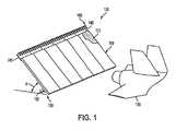
- FIG. 1is a schematic illustration of a p-JBD system or the like.
- FIG. 2is a schematic illustration of the p-JBD system or the like in the deployed position interacting with a jet blast.
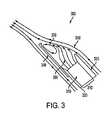
- FIG. 3is a schematic illustration of the ejector plate and the interaction of the jet blast and ambient air.
- FIG. 4(A)is a schematic illustration of the p-JBD system or the like in the stowed position.
- FIG. 4(B)is a schematic illustration of the p-JBD system or the like in the deployed position.
- FIG. 5(A)is a schematic cross-section illustration of a p-JBD system of the like.
- FIG. 5(B)is an enlarged partial schematic view of FIG. 5(A) .
- FIG. 6is an electron micrograph of a stochastic open-cell nickel foam wick.
- FIG. 7is a graphical plot of the effect of compressed pore modification's affect on the wicking height of stochastic open-cell foams.
- FIG. 8(A)is a schematic illustration of a woven mesh screen wick structure suitable for heat pipe and/or plate structures.
- FIG. 8(B)is a schematic illustration of a sintered metal powder wick structure suitable for heat pipe and/or plate structures.
- FIG. 8(C)is a schematic illustration of a sintered metal fiber wick structure suitable for heat pipe and/or plate structures.
- FIG. 8(D)is a schematic illustration of grooves in a heat pipe wall wick structure suitable for heat pipe and/or plate structures.
- FIG. 9is an electron micrograph depiction of a graded pore wick structure.
- FIG. 10is an electron micrograph of a graded pore wick structure.
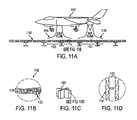
- FIGS. 11 (A)-(D)are schematic illustrations of a generally flat (or angled or contoured as desired) heat plate variant for STOVL aircraft landing pads.
- FIGS. 12 (A)-(B)are schematic illustrations of a p-JBD variant for STOVL aircraft landing pads.
- FIGS. 13 (A)-(B)are schematic illustrations of a p-JBD system in a cross-section view and perspective view, respectively.
- references to one or more “embodiments”are to be understood as describing a particular feature, structure, or characteristic included in at least one implementation of the invention. Phrases such as “in one embodiment” or “in an alternate embodiment” appearing herein describe various embodiments and implementations of the invention, and do not necessarily all refer to the same embodiment, nor are they necessarily mutually exclusive. Numerous specific details are set forth though embodiments of the invention may be practiced without these specific details. Descriptions of certain details and implementations follow, with an overview description of embodiments of the invention, followed by a more detailed description with reference to the drawings.
- Cellular metal lattice structuresoffer efficient structural load support and other functionalities such as energy absorption and various forms of thermal management.
- Low relative density lattices with open cell structuresare highly efficient load supporting systems when configured as the cores of sandwich panels, when the core ligaments are loaded in stretching as opposed to bending modes of deformation.
- These lattice structurescontain low flow resistant pathways.
- sandwich panels with these corescan provide efficient cross flow heat exchange. They are therefore excellent candidates for creating very lightweight multifunctional structures combining load support and thermal management.
- the core relative densitymust also be increased.
- metal honeycomb sandwich structuresbecome more efficient than lattices during out-of-plane compression. These closed cell structures cannot be used for cross flow heat exchange.
- the heat that can be propagated in the out-of-plane directiondepends on the thermal conductivity of the face sheets/webs, the core volume fraction and contribution of convective mechanisms within the core.
- the dissipation of a localized thermal flux applied to one surface of a honeycomb sandwich structurerequires heat to first be transported over the heated face sheet and through the core elements to the opposite face sheet. This can then be ejected to the ambient air via radiation and natural convection. Much more effective transport can be achieved by exploiting convective processes within the sandwich structure, and heat pipe/plate structures are a highly effective means for doing this.
- Heat pipescontain hollow interior regions connecting areas close to the source of heat with others that are cooler.
- the interior surfaces of this hollow spaceare covered with a fluid loaded, wick structure which facilitates capillary driven fluid flow.
- the systemonce evacuated and sealed, acts like a closed-loop two-phase convective system. Heat applied locally to the structure evaporates the fluid and this vapor is rapidly transported to cooler regions where condensation occurs.
- the evaporating liquid in the hot (evaporator) part of the systemis continually replenished by the capillary pumping of the fluid that condenses in the cooler regions.
- This closed cyclehas, among other things, two important consequences: it can result in structures that posses very high specific thermal capacities (because of the very high heat of vaporization for some fluids) and the systems acts as though it has a very high “effective” thermal conductivity because significant thermal energy is transported in the vapor by the latent heat of vaporization/condensation.
- a heat pipeis a closed system, which transfers heat (nearly isothermally) by the evaporation and condensation of a working fluid. Evaporation of the working fluid occurs in the hot region and the latent heat of vaporization is absorbed in the vaporization process. The evaporation results in a slight internal temperature increase and, hence, a pressure differential that causes the vapor to flow from the hot evaporator region to the cooler condenser region. The vapor travels rapidly to the condenser, where it condenses, releasing the heat through condensation. This serves as a very rapid means for transporting thermal energy and isothermalizing a structure.
- a characteristic of the heat pipe/plateis its ability to produce a surface with a very uniform temperature gradient across it.
- An aspect of the present invention p-JBD system and methodutilizes a bimodal method of heat extraction. Firstly, the localized heat flux from the aircraft's jet plume is spread (distributed) and temporarily stored throughout the p-JBD module by the use of heat pipe/plate technologies. Secondly, ambient air is drawn into the bottom of the p-JBD, propagated through the heat exchanger core where it absorbs heat, and is then ejected at the top of the p-JBD system.
- FIG. 1is a schematic illustration of one embodiment of p-JBD system 100 interacting with jet 120 .
- jet 120emits a jet blast (not pictured), it interacts with p-JBD 110 or the like.
- the thermal component of the jet blastis absorbed in to the structure of p-JBD 110 or the like and spread across its surface, and the kinetic component of the jet blast is deflected up and over p-JBD 110 .
- the kinetic componentpasses over the top of p-JBD 110 it must travel over the deployable ejector plate 140 , which creates a low pressure or vacuum region (not pictured) above p-JBD 110 as the kinetic component interacts with the ambient air there.
- p-JBD 110may be coated with a spray-on non-skid protective surface 170 or any other form of coating designed to provide traction. Passive in this context implies a system that does not necessarily require an active cooling system. Although, it should be appreciated that an active cooling system may be added, supplemented or implemented with the disclosed cooling system and related method disclosed throughout this document regarding the present invention methods and systems.
- the p-JBD 110comprises a plurality of first plates 112 in communication or joined (e.g., side-by-side or laterally) with one another along with their respective second plates 111 on the back side with a core 114 disposed there between.
- raise angleas referenced as angle “A”
- size, surface area, contour, and dimensions of the JBD 110may vary as desired or required.
- any of the present invention system and method disclosed hereinmay have, but not necessarily the need for a compatible component system, i.e., the wick material, material used for the plates and core that should be compatible in all the embodiments when applicable such that there should not be any corrosion harmful byproducts that affects the safety and performance of the system when in a exposed in a given or applicable working environment.
- a compatible component systemi.e., the wick material, material used for the plates and core
- the nickel platingmay be applied to the interior surfaces of the p-JBD.
- the wicking fluidmay be high purity water while combatable with the nickel wick that should not come in contact with aluminum surfaces of plates, cores or other applicable components. It should be appreciated that a variety of metals, ceramics and alloys or combination thereof may be implemented as required or desired for any of the components of the present invention system.
- JBD systema variety of welding or joining techniques may be applied, including, but not limited thereto, friction stir welding for effective joining.
- Some of the joints, particularly “lap joints”provide open paths to bare aluminum (or desired or required material) of the plates or cores (for example), which in turn may produce undesirable corrosion product in certain instances.
- optionally special sealantsmay be employed which are applied during welding (e.g., friction stir welding or as desired or required) to those lap joints.
- FIG. 2is a schematic illustration of one embodiment of p-JBD system 200 or the like.
- the p-JBD system 200may be raised into position by elevating gear 220 .
- the ambient cooling airflow in the p-JBD system 200is generated via an ejector plate 213 which is located at the top of the JBD 200 along its back surface, second plate 211 .
- the ejector platemay be at an alternate location as desired or required and/or may have a have a size and contour as desired or required.
- engine exhaust 250 from an aircraftimpacts the front surface of the JBD 212 , it has two main components to its energy content.
- thermal component 251which is heat, and is deposited on the front side, or first plate 212 , of JBD 200 .
- kinetic or mass flow component 252to the engine exhaust 250 .
- the kinetic component 252 of the exhaustimpacts the JBD's front surface 212 , the gas is compressed and directed upwards over the top of the JBD 200 .
- this flowgoes over the top of the JBD 200 it interacts with the ejector plate 213 with lip 215 , for example (other sizes and contours of the lip or lip-like structure or function/effect thereof may be implemented as desired or required).
- This ejector plate 213creates a low pressure, or vacuum region 270 which draws cool ambient air 260 through the heat exchanger, the cellular core 210 of the p-JBD system 200 .
- the inlet 214 for this ambient air 260is located near the bottom of the JBD closest to the aircraft carrier's deck 230 . In other embodiments, the inlet could be placed elsewhere as desired or required.
- cooling fluidmay be actively pumped into the core as well.
- cooling fluidmay be actively pumped into the core instead; or a combination of passive fluid and actively induced fluid.
- JBD system or thermal spreading face as disclosed throughoutdoes not necessarily need to be able to recline, be mobile or be deployable, but rather may fixed in a position and/or location if desired or required.
- FIG. 3shows a schematic illustration of the ejector plate and the interaction of a jet blast and ambient air drawn through the heat exchanger core; it is a close-up of the top portion of the p-JBD system 300 illustrating the engine exhaust, jet plume 350 and mixing region 370 created by the ejector plate 340 .
- the ejector plate 310which maximizes the amount of ambient air flow 360 that can be drawn through a particular heat exchanger core 310 . Since the geometry of the heat exchanger core 310 in the p-JBD 300 is fixed, the optimal length will depend upon the exhaust characteristics (velocity and mass flow) of the jet plume 350 . In one embodiment, the effective length of the ejector plate 340 would be either fixed, for all aircraft launch scenarios; in another embodiment the ejector plate 340 would have a variable length that would be optimized for each individual aircraft launched from a carrier based fleet.
- FIG. 4(A)is a schematic illustration of the p-JBD system or the like in the stowed position and FIG. 4(B) is a schematic illustration of the p-JBD system in the deployed position.
- the p-JBDis used to deflect the jet plumes of aircraft on an aircraft carrier.
- FIG. 4(A)when stowed, the p-JBD 410 is flush with the carrier deck 440 .
- the p-JBD panel 410 to which the elevating gear 420 is attachedoccupies a pit region 450 cut out of the deck 440 .
- the p-JBD 410when the p-JBD 410 is in the stowed position, it serves as a deck over which aircraft and carrier personnel may pass. While p-JBD 410 is in the stowed position, ejector plate 430 is also set in its own stowed position, and is not extended. When the p-JBD 410 is in the deployed position, it is capable of deflecting jet blasts to protect aircraft, equipment, and personnel on deck 440 . When deployed, p-JBD 410 is lifted out of pit region 450 by elevating gear 420 . When p-JBD 410 is deployed, ejector plate 430 is extended into a deployed position as well. In an exemplary approach of an embodiment of the JBD system, the system may utilize the existing hydraulic systems, other applicable system or elevating/stowing/mobilizing gear for panel elevation and stowage.
- FIG. 5(A)is a schematic illustration of a detailed cross section of one embodiment of a p-JBD system 500 or the like.
- FIG. 5(B)is an enlarged partial schematic view of FIG. 5(A) .
- the designcan be separated into three distinct components: the first plate 510 , which is the front face and serves as a thermal spreader (evaporator), the cellular core 520 which serves as a heat exchanger and the second plate 530 , which is the rear face and serves as a fluid reservoir (condenser).
- these three componentsform a sandwich structure 505 with a series of vertical I-webs 522 forming the cellular core 520 .
- the p-JBDis a hierarchical structure in that each of the three main components: the first plate 510 , cellular core 520 and rear face 530 are also sandwich structures themselves.
- each of the core regions of the front face 510 , cellular core 520 and rear face 530are interconnected forming an intricate network of void space called the vapor core 550 .
- the entire p-JBDserves as a heat plate, promoting bi-modal heat extraction as heat is spread throughout the structure, moving from the first plate 510 though the cellular core 520 to the second plate 530 .
- the unique geometries of these core regionsare tailored to support a specific structural load as aircraft and equipment are rolled over the p-JBD's when they are in the stowed position.
- I-webs 522are extruded core elements with angled heat pipe channels and keys to interlock their edges. It should be appreciated that cellular core 520 could be constructed in other ways, such as through the use of a plurality of H-beam structures, I-beam, textile layers, honeycomb or honeycomb-like structures, or corrugated or corrugated-like structures.
- any or all of the components of the JBD system 500 and any embodiments of the present invention disclosed throughoutmay be assembled by extruded elements and/or any of the components or portions of components may have portions or segments machined out, removed or shaped.
- any or all of the components of the JBD system 500 and any embodiments of the present invention disclosed throughoutmay be joined using any type of welding method or any available method of joining or coupling materials or components/structures/devices.
- the core support regions 511 and 531 of the first and second plates, respectivelyare cruciform (cross shaped) elements. It is envisioned that any shape element can be used in place of the cruciform elements as long as they provide the necessary structural integrity and support the thermal requirements. This is also the case for the core elements 521 of the cellular core 520 , which are shown as simple corrugations.
- friction stir weldingis a method of joining or coupling the components. However, it is envisioned that any standard method of joining materials, as well as coupling may be used.
- the working fluidevaporates and the vapor is rapidly transported to cooler regions where condensation occurs.
- capillary pumping of the fluid that condenses in the cooler regionsmay be necessary. This is accomplished by the use of a wicking material 590 which lines all internal surfaces of the p-JBD module.
- This wick material 590provides a dual role in the heat pipes operation. First, it acts as the fluid reservoir or storage region and secondly it provides the capillary pumping required replenishing the working fluid to the evaporator region.
- INCOFOAM® nickel foamcan be used as the wicking material for the flat heat pipe thermal spreader, such as first plate 510 in FIG. 5 .
- Ni foamor any available, desirable, required material
- INCOFOAM®is a high-purity (>99.98% wt.) stochastic open-cell foam material which is produced by chemical vapor deposition of nickel tetracarbonyl (Ni(CO) 4 ) onto an open-cell polyurethane substrate, followed by a high-temperature ( ⁇ 1,000° C.) (or any available, desirable, required temperatures or materials) heat treatment which burns out the polymer foam template and sinters/anneals the nickel ligaments.
- the as-received nickel foamhas a thickness of 1.95 mm and an area density of 500 g/m 2 (or any available, desirable, required thickness or density) which corresponds to a relative density of 0.03.
- the reported cell size of 90 pores per inch (PPI)corresponds to an average cell size (diameter) of ⁇ 600 ⁇ m (or any available, desirable, required size), as shown in FIG. 6 .
- a porous solidcan be modeled as an array of parallel capillary cylindrical tubes.
- the rise in a column of an incompressible fluid in a capillary tubeis known as the capillary rise problem.
- the capillary rise problemis developed for a single capillary tube and then the analysis extended to stochastic open-cell nickel foams.
- the expression for the equilibrium height for a single capillary tubecan be extrapolated to the stochastic open-cell nickel foam. Strips of the foam ⁇ 25 mm wide by ⁇ 300 mm long were cut and compressed (in thickness) varying amounts to modify the effective pore size/shape and suspended in a container of deionized water and the equilibrium height of the water rise measured (or any available, desirable, required size, width or length).
- the effective pore diameter, d, of the compressed foamcan be expressed as:
- dd o ⁇ t t o ( 3 )
- d ois the initial average pore size of the as-received foam ( ⁇ 600 ⁇ m)
- tthe thickness of the compressed foam
- t othe thickness of the as-received foam (1.95 mm) assuming that during compression, deformation is constrained in the through thickness direction (or any available, desirable, required length or size).
- FIG. 7is a graphical plot of the effect of compressed pore modification's affect on the wicking height of stochastic open-cell foams and it shows the experimentally measured equilibrium height for the compressed nickel foam as well as the predicted capillary rise in a single tube of equivalent pore size as a function of compression ratio, t/t o , and the corresponding effective pore diameter, d serves as a guideline for the wicking ability of these compressed stochastic open-cell nickel foams.
- the wicking structure 590 in FIG. 5may serve two main functions in the heat pipe operation: it is the vehicle through which, and provides the mechanism by which the working fluid is returned from the condenser, such as second plate 530 , to the evaporator, such as first plate 510 , and also ensures that the working fluid is evenly distributed over the evaporator surface. While one embodiment employs a stochastic open-cell foam, such as wicking structure 590 , in other embodiments numerous wick topologies, including, but not limited to woven mesh screens, sintered metal fibers and powders and small grooves within the heat pipe walls, which are well known in prior art, are applicable for use in the p-JBD system.
- FIGS. 8 (A)-(D)show schematic illustrations of alternate wicking topologies.
- a wicking topologysuch as a woven mesh screen 810 depicted in FIG. 8(A) would be employed.
- a sintered metal powder 820 or other material as depicted in FIG. 8(B)could be used as the wicking topology.
- a sintered metal fiber 830 or other material as depicted in FIG. 8(C)could be used as the wicking topology.
- Yet another alternative embodimentwould employ a simple wicking topology of small grooves 845 in the heat pipe walls 840 as shown in FIG. 8(D) .
- FIG. 9 and FIG. 10are electron micrograph depictions of two different graded pore wick structures manufactured by sintering several lawyers of compressed open-cell nickel foam together.
- the present inventioncan be used to passively deflect hot gas jets, such as those from an aircraft engine, as described above.
- the inventionalso provides means for accomplishing the more general goal of dispersing an intense local heat source, such as a gas jet plume (when present) into the environment while also providing a high strength structure.
- an intense local heat sourcesuch as a gas jet plume (when present) into the environment while also providing a high strength structure.
- the p-JBD system or the likemay also be used for other localized heat sources such as gas turbine engines or other hot, fast moving (high kinetic energy) gas streams without regards to their means of production.
- the p-JBDcould support an F-35 Joint Strike Fighter (JSF) or any aircraft or spacecraft.
- the F-35 (JSF)is designed to replace aging fighter inventories.
- the F-35will be manufactured in three versions: one for conventional-takeoff-and-landing (CTOL), an aircraft-carrier version (CV) and a short-takeoff/vertical landing variant (STOVL).
- CTOLconventional-takeoff-and-landing
- CVaircraft-carrier version
- STOVLshort-takeoff/vertical landing variant
- the thrust vectoring exhaust nozzleis directed downward (the same direction as the lift fan) and the aircraft lands vertically. In this scenario, the hot exhaust gases heat the landing pad leading to a wide range of thermal management issues.
- the flat heat plate thermal spreader portion of the p-JBD systemcan be manufactured as a portable or stationary landing pad.
- a schematic illustration of such a landing pad 1100is shown in FIGS. 11 (A)-(D).
- the passive thermal spreader 1120is composed of core support regions 1123 , such as core support region 511 in FIG. 5 , which are lined with a wicking structure 1124 , such as wicking structure 590 in FIG. 5 , thereby enabling the passive thermal spreader 1120 to function as a heat plate.
- FIG. 11(B)is an enlarged partial schematic view of the landing pad 1100 of FIG. 11(A) illustrating the core support region 1123 .
- FIG. 11(C)is an enlarged partial schematic view of the core support region 1123 of FIG. 11(B) .
- FIG. 11(D)is an enlarged partial schematic view of the core support region 1123 of FIG. 11(C) illustrating the wicking structure 1124 .
- any component, subcomponent, system, sub-system, sub-apparatus, or apparatus of the JBD systemmay comprise any material or combination of materials as required and desired. It should be appreciated that any component, subcomponent, system, sub-system, sub-apparatus, or apparatus of the JBD system may be of any size, dimension, contour, density, weight, location, mobility, portability or stability as desired or required. Still yet, it should be appreciated that any component, subcomponent, system, sub-system, sub-apparatus, or apparatus of the JBD system may be connected, coupled, adjoined, fused, extruded, machined or welded, etc. together as desired or required. Further yet, it should be appreciated that any component, subcomponent, system, sub-system, sub-apparatus, or apparatus of the JBD system may be integrally combined in one module or unit or separately connected, detachable or exchangeable as desired or required.
- FIG. 12Another embodiment of the present invention is a portable or stationary landing pad consisting of both the thermal spreading top face, such as first face 510 in FIG. 5 , and the heat exchanger, such as cellular core 520 in FIG. 5 , similar to the p-JBD module design previously shown.
- a schematic illustration of such a landing padis shown in FIG. 12 .
- heat from the hot exhaust plume 1250 of the jet 1210is removed from the landing pad 1200 via convection of the cool lift fan gas 1260 on the thermal spreading face 1220 , such as first plate 510 in FIG. 5 , as well as via convection through the heat exchanger, cellular core 1230 , such as cellular core 520 in FIG. 5 .
- Ejector plates 1240 located along two edges of the landing padinduce the flow of cooling ambient air from the sides of the landing pad 1200 through the cellular core 1230 much like an embodiment of the p-JBD design for aircraft carrier use, as shown in FIG. 1 .
- the thermal spreading face 1220is composed of core support regions 1221 that are lined with a wicking structure, such as wicking structure 1124 in FIG. 11 , thereby enabling the thermal spreading face 1220 to serve as a heat plate to facilitate the efficient spreading of thermal energy throughout its structure.
- Cellular core 1230is composed of pyramidal truss heat pipes 1231 that facilitate the efficient transfer of thermal energy throughout their structure as well.
- FIG. 12(B)is an enlarged partial schematic view of the landing pad 1200 of FIG. 12(A) illustrating the thermal spreading face 1220 and truss structures 1231 of the cellular core 1230 .
- FIGS. 13 (A)-(B)an exemplary non-limiting method of manufacturing is set forth which involves the assembly of extruded aluminum (or a metal, material or combination of materials or metals as desired or required) elements that are joined by welding, for example, friction stir welding to form the panel assembly.
- weldingfor example, friction stir welding
- a typical cross-section of the extrusionis shown in FIG. 13(A) .
- the extrusionsare machined and joined together forming a single JBD module.
- Various sizes, dimensions and contoursmay be employed as desired or required.
- a non-limiting selectionmay be 6′ ⁇ 14′ single JBD module.
- FIG. 13(B)shows a single extrusion.
- the width of the extrusionsmay vary as desired or required. In one aspect the width of the extrusion may be limited by the billet size of the starting material.
- an aspect of various embodiments of the present invention discussed throughoutprovides, but not limited thereto, a novel method (and related structure) of manufacturing a passive JBD which employs an integrated multifunctional concept encompassing all structural and thermal requirements. The concept integrates heat pipe technology into a structural sandwich panel forming the passive modules by joining extruded elements.
- the designcan be employed by an extrusion process to provide a first plate 510 , which is the front face and serves as a thermal spreader (evaporator) and a cellular core 520 which serves as a heat exchanger.
- a second plate 530may be joined (or the second plate may also be part of the extrusion process of first plate 510 and cellular core 520 ), which is the rear face and serves as a fluid reservoir (condenser).
- these three componentsform a sandwich structure 505 with a series of vertical I-webs 522 forming the cellular core 520 .
- the p-JBD or the likemay be a hierarchical structure in that each of the three main components: the first plate 510 , cellular core 520 and rear face 530 are also sandwich structures themselves.
- each of the core regions of the front face 510 , cellular core 520 and rear face 530are interconnected forming an intricate network of void space called the vapor core 550 .
- the entire p-JBDserves as a heat plate, promoting bi-modal heat extraction as heat is spread throughout the structure, moving from the first plate 510 though the cellular core 520 to the second plate 530 .
- the unique geometries of these core regionsare tailored to support a specific structural load as aircraft and equipment are rolled over the p-JBD's when they are in the stowed position.
- I-webs 522are extruded core elements themselves with angled heat pipe channels and keys to interlock their edges. It should be appreciated that cellular core 520 could be constructed in other ways, such as through the use of a plurality of H-beam structures, I-beam, textile layers, honeycomb or honeycomb-like structures, or corrugated or corrugated-like structures.
- the cores, panels/plates and related sandwich structuresmay comprise stacked textile layers as taught or disclosed in PCT International Application No. PCT/US01/17363, entitled “Multifunctional Periodic Cellular Solids And The Method of Making Thereof,” filed May 29, 2001, and corresponding U.S. application Ser. No. 10/296,728, entitled “Multifunctional Periodic Cellular Solids and the Method of Making Thereof,” filed Nov. 25, 2002, of which the entire disclosures are hereby incorporated by reference herein in their entirety.
- the textile layer related cores and/or panels/platesmay comprise tubular filaments, wire filaments, woven mesh, woven material, knitted mesh, braided mesh, triaxial mesh, quasi-triaxial mesh, three-dimensional elements, H-beam, I-beam, corrugated, and Honeycomb.
- the cores and/or panels/plates and related sandwich structuresmay comprise an open cell having hollow ligaments as discussed in PCT International Application No. PCT/US01/22266, entitled “Method and Apparatus For Heat Exchange Using Hollow Foams and Interconnected Networks and Method of Making the Same,” filed Jul. 16, 2001, and corresponding U.S. application Ser. No. 10/333,004, entitled “Heat Exchange Foam,” filed Jan. 14, 2003, of which the entire disclosures are hereby incorporated by reference herein in their entirety.
- Ligamentsmay be stochastically ordered or periodically ordered.
- the cores and/or panels/platesmay comprise open cell interconnected network having hollow ligaments as well.
- the cores and/or panels/plates and related sandwich structuresmay comprise three-dimensional space filling layers as taught in PCT International Application No. PCT/US02/17942, entitled “Multifunctional Periodic Cellular Solids And The Method of Making Thereof,” filed Jun. 6, 2002, and corresponding U.S. application Ser. No. 10/479,833, entitled “Multifunctional Periodic Cellular Solids And The Method of Making Thereof,” filed on Dec. 5, 2003, of which the entire disclosures are hereby incorporated by reference herein in their entirety.
- the three-dimensional space filling layer related cores and/or panels/platesmay comprise out-of-plane truss units.
- the truss unitsmay be tetrahedral, pyramidal, Kagome, combinations thereof and other non-limiting arrangements.
- the cores and/or panels/plates and related sandwich structuresmay comprise periodic cellular structure layers as taught in PCT International Application No. PCT/US03/16844, entitled “Method for Manufacture of Periodic Cellular Structure and Resulting Periodic Cellular Structure,” filed May 29, 2003, and corresponding U.S. application Ser. No. 10/515,572, entitled “Multifunctional Periodic Cellular Solids And The Method of Making Thereof,” filed Nov. 23, 2004, of which the entire disclosures are hereby incorporated by reference herein in their entirety.
- the periodic cellular structure layer related cores and/or plates/panelsmay comprise truss elements or units.
- the truss elements or unitsmay have a plurality of wicking elements located inside to facilitate heat exchange.
- the cores and/or panels/plates and related sandwich structuresmay comprise one or more arrays of cellular housing layers as taught in PCT International Application No. PCT/US03/23043, entitled “Method for Manufacture of Cellular Materials and Structures for Blast and Impact Mitigation and Resulting Structure,” filed Jul. 23, 2003, and corresponding U.S. application Ser. No. 10/522,068, entitled “Multifunctional Periodic Cellular Solids And The Method of Making Thereof,” filed Jan. 21, 2005, of which the entire disclosures are hereby incorporated by reference herein in their entirety.
- the arrays of cellular housing layer related cores and/or plates/panelsmay comprise interior cellular housing cores disposed therein the housing.
- the present inventiongeneral structural material may be involved in architecture (for example: pillars, walls, shielding, foundations or floors for tall buildings or pillars, wall shielding floors, for regular buildings and houses), the civil engineering field (for example; road facilities such as noise resistant walls and crash barriers, road paving materials, permanent and portable aircraft landing runways, pipes, segment materials for tunnels, segment materials for underwater tunnels, tube structural materials, main beams of bridges, bridge floors, girders, cross beams of bridges, girder walls, piers, bridge substructures, towers, dikes and dams, guide ways, railroads, ocean structures such as breakwaters and wharf protection for harbor facilities, floating piers/oil excavation or production platforms, airport structures such as runways) and the machine structure field (frame structures for carrying system, carrying pallets, frame structure for robots, etc.), the automobile (the body, frame, doors, chassis, roof
- the core and/or panels/plates and related sandwich structuresmay comprise a cellular structure and optionally having nodes therein as taught or disclosed in PCT International Application No. PCT/US03/27606, entitled “Method for Manufacture of Truss Core Sandwich. Structures and Related Structures Thereof,” filed Sep. 3, 2003, and corresponding U.S. application Ser. No. 10/526,296, entitled “Method for Manufacture of Truss Core Sandwich Structures and Related Structures Thereof,” filed Mar. 1, 2005, of which the entire disclosures are hereby incorporated by reference herein in their entirety.
- the cellular structure layer related cores and/or panels/platesmay comprise tetrahedral, pyramidal, Kagome, cone, frustum, or combinations thereof and other non-limiting arrangements.
- the core, first plate/panel, and second plate/panel, and related sandwich structuresmay comprise a multilayer truss structure as taught in PCT International Application No. PCT/US04/04608, entitled “Methods for Manufacture of Multilayered Multifunctional Truss Structures and Related Structures There from,” filed Feb. 17, 2004, and corresponding U.S. application Ser. No. 10/545,042, entitled “Methods for Manufacture of Multilayered Multifunctional Truss Structures and Related Structures There from,” filed Aug. 11, 2005, of which the entire disclosures are hereby incorporated by reference herein in their entirety, as well as the related method of manufacturing thereof.
- any activitycan be repeated, any activity can be performed by multiple entities, and/or any element can be duplicated. Further, any activity or element can be excluded, the sequence of activities can vary, and/or the interrelationship of elements can vary. Unless clearly specified to the contrary, there is no requirement for any particular described or illustrated activity or element, any particular sequence or such activities, any particular size, speed, material, dimension or frequency, or any particularly interrelationship of such elements. Accordingly, the descriptions and drawings are to be regarded as illustrative in nature, and not as restrictive. Moreover, when any number or range is described herein, unless clearly stated otherwise, that number or range is approximate. When any range is described herein, unless clearly stated otherwise, that range includes all values therein and all sub ranges therein.
Landscapes
- Engineering & Computer Science (AREA)
- Mechanical Engineering (AREA)
- Aviation & Aerospace Engineering (AREA)
- Cooling Or The Like Of Electrical Apparatus (AREA)
Abstract
Description
where Pvand Plare the pressure of the vapor and liquid, respectively, σ the surface tension of the liquid, θ the contact angle of the liquid and r the radius of the capillary tube. Assuming a condition of equilibrium exists, the height of the liquid within the capillary tube is expressed as:
where g is the acceleration due to gravity (9.8 m/s2) and ρvand ρlare the densities of the vapor and liquid phases. Assuming, σ=0.061 N/m, ρl=958.3 kg/m3, ρv=0.597 kg/m3and good wetability cos θ=1, the equilibrium height of water in a capillary tube can be predicted by Eqn. (3).
where dois the initial average pore size of the as-received foam (˜600 μm), t the thickness of the compressed foam and tothe thickness of the as-received foam (1.95 mm) assuming that during compression, deformation is constrained in the through thickness direction (or any available, desirable, required length or size).
Claims (61)
Priority Applications (1)
| Application Number | Priority Date | Filing Date | Title |
|---|---|---|---|
| US12/301,916US8360361B2 (en) | 2006-05-23 | 2007-05-23 | Method and apparatus for jet blast deflection |
Applications Claiming Priority (6)
| Application Number | Priority Date | Filing Date | Title |
|---|---|---|---|
| US80262306P | 2006-05-23 | 2006-05-23 | |
| US80262406P | 2006-05-23 | 2006-05-23 | |
| US81809906P | 2006-06-30 | 2006-06-30 | |
| US83332606P | 2006-07-26 | 2006-07-26 | |
| US12/301,916US8360361B2 (en) | 2006-05-23 | 2007-05-23 | Method and apparatus for jet blast deflection |
| PCT/US2007/012268WO2007139814A2 (en) | 2006-05-23 | 2007-05-23 | Method and apparatus for jet blast deflection |
Publications (2)
| Publication Number | Publication Date |
|---|---|
| US20110042512A1 US20110042512A1 (en) | 2011-02-24 |
| US8360361B2true US8360361B2 (en) | 2013-01-29 |
Family
ID=38779184
Family Applications (1)
| Application Number | Title | Priority Date | Filing Date |
|---|---|---|---|
| US12/301,916Expired - Fee RelatedUS8360361B2 (en) | 2006-05-23 | 2007-05-23 | Method and apparatus for jet blast deflection |
Country Status (2)
| Country | Link |
|---|---|
| US (1) | US8360361B2 (en) |
| WO (1) | WO2007139814A2 (en) |
Cited By (8)
| Publication number | Priority date | Publication date | Assignee | Title |
|---|---|---|---|---|
| US9056688B1 (en) | 2014-10-20 | 2015-06-16 | Blast Deflectors, Inc. | Apparatus and method for deflecting airflow in a structure with a vented rear wall |
| US9745736B2 (en) | 2013-08-27 | 2017-08-29 | University Of Virginia Patent Foundation | Three-dimensional space frames assembled from component pieces and methods for making the same |
| US9915228B2 (en) | 2013-08-16 | 2018-03-13 | United Technologies Corporation | Air with integral spring for a gas turbine engine exhaust drive |
| US10217692B2 (en) | 2012-07-18 | 2019-02-26 | University Of Virginia Patent Foundation | Heat transfer device for high heat flux applications and related methods thereof |
| US10378451B2 (en) | 2013-09-13 | 2019-08-13 | United Technologies Corporation | Large displacement high temperature seal |
| US10378861B2 (en) | 2014-09-04 | 2019-08-13 | University Of Virginia Patent Foundation | Impulse mitigation systems for media impacts and related methods thereof |
| US11788797B2 (en) | 2012-07-18 | 2023-10-17 | University Of Virginia Patent Foundation | Heat transfer device for high heat flux applications and related methods thereof |
| US12059371B2 (en) | 2022-01-04 | 2024-08-13 | Bluexthermal, Inc. | Ocular region heat transfer devices and associated systems and methods |
Families Citing this family (16)
| Publication number | Priority date | Publication date | Assignee | Title |
|---|---|---|---|---|
| FR876M (en) | 1960-10-12 | 1961-10-16 | ||
| US20100038480A1 (en)* | 2008-08-14 | 2010-02-18 | Cna Corporation | Jet/efflux outwash barrier system for stovl, tiltrotor, and helicopter aircraft |
| US8465825B1 (en)* | 2009-05-29 | 2013-06-18 | Hrl Laboratories, Llc | Micro-truss based composite friction-and-wear apparatus and methods of manufacturing the same |
| WO2011142841A2 (en)* | 2010-01-14 | 2011-11-17 | University Of Virginia Patent Foundation | Multifunctional thermal management system and related method |
| DE102013000691A1 (en)* | 2013-01-15 | 2014-07-17 | Kai Klinder | Sound absorbing hollow cavity has main portion that is provided with honeycomb structure with extremely thin inner walls and damping element |
| US20160061145A1 (en)* | 2013-04-03 | 2016-03-03 | Rajan Kumar | Hybrid Flow Control Method |
| US20160005524A1 (en)* | 2014-07-07 | 2016-01-07 | Hamilton Sundstrand Corporation | Immersion cooled toroid inductor assembly |
| FR3027929A1 (en)* | 2014-10-30 | 2016-05-06 | Jacques Peugeot | ARTIFICIALLY ARTIFICIALLY ARTIFICIENT ARRANGEMENT FOR AN AIRCRAFT OPERATING AIR ZONE FOR DYNAMIC FLIGHT |
| HUP1500403A1 (en)* | 2015-09-04 | 2017-03-28 | Mol Magyar Olaj- Es Gazipari Nyilvanosan Muekoedoe Reszvenytarsasag | Self-supporting, self-cleaning, open-cell metal foams containing transition metals, non-metals and/or their alloys and/or oxides and a process for their production |
| US10184759B2 (en) | 2015-11-17 | 2019-01-22 | University Of Virgina Patent Foundation | Lightweight ballistic resistant anti-intrusion systems and related methods thereof |
| CN106347702B (en)* | 2016-08-24 | 2018-07-27 | 东南大学 | A kind of gas-jetting flow-guiding plate |
| CN113320711B (en)* | 2021-07-06 | 2024-12-20 | 湖北航特装备制造股份有限公司 | A mobile modular high-strength anti-blow guide screen |
| CN113895644B (en)* | 2021-11-19 | 2023-11-28 | 中国航发沈阳发动机研究所 | High-temperature tail gas flow control device for aircraft taking off in front of flow deflector |
| CN114087069B (en)* | 2021-11-19 | 2023-02-28 | 中国航发沈阳发动机研究所 | Diversion device for avoiding temperature distortion of engine inlet |
| CN114021731B (en)* | 2021-11-29 | 2024-08-02 | 中国科学技术大学 | A device and method for generating complex tensor network state |
| CN115263604B (en)* | 2022-06-22 | 2024-10-01 | 北京控制工程研究所 | Opposite hole mutual impact injector applied to light quick-response double-component engine |
Citations (198)
| Publication number | Priority date | Publication date | Assignee | Title |
|---|---|---|---|---|
| US1154254A (en) | 1909-11-05 | 1915-09-21 | Universal Electric Welding Co | Sheet-metal panel-work. |
| US2288104A (en) | 1942-06-30 | o i v it | ||
| US2481046A (en) | 1947-11-13 | 1949-09-06 | Western Engineering Associates | Panel structure |
| US2692024A (en)* | 1950-11-25 | 1954-10-19 | Reaction Motors Inc | Jet blast cooling and quieting device |
| US2726830A (en)* | 1953-06-11 | 1955-12-13 | Armco Steel Corp | Blast fence for jet engines |
| US2789076A (en) | 1953-09-21 | 1957-04-16 | Frieder | Laminated ballistic fabric |
| US2826382A (en)* | 1953-03-06 | 1958-03-11 | Boeing Co | Jet engine exhaust deflector |
| US3037726A (en)* | 1959-07-02 | 1962-06-05 | Stanray Corp | Engine blast absorbing fence |
| US3087693A (en)* | 1958-11-21 | 1963-04-30 | Power Jets Res & Dev Ltd | Airfield ground equipment for vertical take-off aircraft |
| US3096956A (en)* | 1960-07-29 | 1963-07-09 | Snecma | Airstrip for vertical take-off aircraft |
| US3191728A (en)* | 1960-12-29 | 1965-06-29 | David Louis Fernand | Metal panel and its application in an anti-blast barrier in particular for air-ports |
| US3298402A (en) | 1965-02-15 | 1967-01-17 | Jesse R Hale | Method for fabricating space structures |
| US3436036A (en)* | 1965-12-23 | 1969-04-01 | Entwicklungsring Sued Gmbh | Takeoff and landing platform for vertical takeoff and landing planes |
| US3783969A (en) | 1968-05-27 | 1974-01-08 | Pall Corp | Acoustic insulation comprising anisometric compressed and bonded multilayer knitted wire mesh composites |
| US3795288A (en) | 1968-05-27 | 1974-03-05 | Pall Corp | Gas conduit with acoustic insulation comprising anisometric compressed and bonded multilayer knitted wire mesh composites |
| US3857217A (en) | 1972-11-15 | 1974-12-31 | W Reps | Lightweight, rigid structural panel for walls, ceilings and the like |
| US3869778A (en) | 1971-12-27 | 1975-03-11 | Raymond W Yancey | Article of manufacture with twisted web |
| US3971072A (en) | 1971-06-28 | 1976-07-27 | Armellino Richard A | Lightweight armor and method of fabrication |
| US3996082A (en) | 1975-08-14 | 1976-12-07 | William C. Heller, Jr. | Composite bonding method and means |
| US4001478A (en) | 1967-10-16 | 1977-01-04 | Avco Corporation | Three-dimensional fabric material |
| US4019540A (en) | 1976-03-12 | 1977-04-26 | Mcdonnell Douglas Corporation | Loom for producing three dimensional weaves |
| US4027476A (en) | 1973-10-15 | 1977-06-07 | Rocket Research Corporation | Composite catalyst bed and method for making the same |
| US4038440A (en) | 1972-01-24 | 1977-07-26 | Avco Corporation | Three dimensional fabric material |
| US4037751A (en) | 1973-04-18 | 1977-07-26 | Summa Corporation | Insulation system |
| US4067956A (en) | 1976-10-08 | 1978-01-10 | Chemotronics International, Inc. | Reticulated anisotropic porous vitreous carbon |
| US4129089A (en) | 1976-10-18 | 1978-12-12 | Paidoussis Michael P | Marine propulsion apparatus |
| US4130233A (en) | 1977-05-23 | 1978-12-19 | John Chisholm | Process for making porous metal heat sink from clad aluminum wire |
| US4194255A (en) | 1977-10-07 | 1980-03-25 | Willy Poppe | Foam spring |
| US4223053A (en) | 1978-08-07 | 1980-09-16 | The Boeing Company | Truss core panels |
| US4291732A (en) | 1979-02-26 | 1981-09-29 | Covington Brothers, Inc. | Method and apparatus for manufacture of wire truss and sinuous strut therefor |
| US4450338A (en) | 1982-05-04 | 1984-05-22 | Tre Corporation | Method of fabricating a truss core sandwich panel |
| US4453367A (en) | 1981-07-10 | 1984-06-12 | General Electric Company | Honeycomb core material and sandwich construction structural building materials incorporating same |
| US4469077A (en) | 1982-05-24 | 1984-09-04 | Wooldridge Bobby M | Fuel mixture method and apparatus for internal combustion engines |
| US4518444A (en) | 1982-02-05 | 1985-05-21 | Bbc Brown, Boveri & Company, Limited | Material which is at least partially made from a constituent having a one-way shape memory effect and process to produce said material |
| US4522860A (en) | 1983-01-10 | 1985-06-11 | Metalcore Limited | Material for reinforcing core in a structure |
| US4529640A (en) | 1983-04-08 | 1985-07-16 | Goodyear Aerospace Corporation | Spaced armor |
| US4530197A (en) | 1983-06-29 | 1985-07-23 | Rockwell International Corporation | Thick core sandwich structures and method of fabrication thereof |
| US4531511A (en) | 1983-07-14 | 1985-07-30 | Hochberg Nelson D | Means for controlling heat flux |
| US4541594A (en)* | 1980-12-22 | 1985-09-17 | General Dynamics Corporation | Takeoff and landing platform for V/STOL airplane |
| US4625710A (en) | 1984-06-21 | 1986-12-02 | Sumitomo Chemical Company, Limited | Hollow structure panel for heat storage material and process for producing heat storage material panel using the same |
| US4632716A (en) | 1983-06-08 | 1986-12-30 | Wangner Systems Corporation | Woven low permeability fabric and method |
| US4639388A (en) | 1985-02-12 | 1987-01-27 | Chromalloy American Corporation | Ceramic-metal composites |
| US4687702A (en) | 1986-06-20 | 1987-08-18 | Chemtronics | Structural insulating panel and method of making the panel |
| US4756943A (en) | 1985-11-14 | 1988-07-12 | Messerschmitt-Boelkow-Blohm Gmbh | Sandwich structural part |
| US4758299A (en) | 1986-07-01 | 1988-07-19 | Roll-O-Matic Chain Company | Method of making composite foam structural laminate |
| US4765396A (en) | 1986-12-16 | 1988-08-23 | The United States Of America As Represented By The Administrator Of The National Aeronautics And Space Administration | Polymeric heat pipe wick |
| US4806815A (en) | 1985-04-03 | 1989-02-21 | Naomitsu Tokieda | Linear motion actuator utilizing extended shape memory alloy member |
| US4819719A (en) | 1987-01-20 | 1989-04-11 | Mcdonnell Douglas Corporation | Enhanced evaporator surface |
| US4859541A (en) | 1986-09-06 | 1989-08-22 | Metallgesellschaft Ag | Safety structure |
| US4864824A (en) | 1988-10-31 | 1989-09-12 | American Telephone And Telegraph Company, At&T Bell Laboratories | Thin film shape memory alloy and method for producing |
| US4881981A (en) | 1988-04-20 | 1989-11-21 | Johnson Service Company | Method for producing a shape memory alloy member having specific physical and mechanical properties |
| US4883116A (en) | 1989-01-31 | 1989-11-28 | The United States Of America As Represented By The Administrator Of The National Aeronautics And Space Administration | Ceramic heat pipe wick |
| US4916027A (en) | 1988-01-21 | 1990-04-10 | Rockwell International Corporation | Primary structure multi-layer insulation |
| US4918281A (en) | 1980-07-02 | 1990-04-17 | Rohr Industries, Inc. | Method of manufacturing lightweight thermo-barrier material |
| US4923544A (en) | 1988-11-02 | 1990-05-08 | Tetrahex, Inc. | Method of manufacturing a tetrahexaconal truss structure |
| US4955135A (en) | 1988-11-16 | 1990-09-11 | Vapor Technologies Inc. | Method of making matrix composites |
| US4958806A (en)* | 1988-12-14 | 1990-09-25 | Nihon Samicon Co., Ltd. | Snowstorm guard fence structures and jet roofs |
| US4968367A (en) | 1987-09-08 | 1990-11-06 | Stamicarbon B.V. | Process for producing formed article of tubular elements |
| US5002378A (en) | 1990-08-03 | 1991-03-26 | Litton Systems, Inc. | Light weight cooled mirror |
| US5011638A (en) | 1988-06-17 | 1991-04-30 | Vapor Technologies, Inc. | Method of making open-pore structures |
| US5040966A (en) | 1988-11-02 | 1991-08-20 | Tetrahex, Inc. | Die for making a tetrahexagonal truss structure |
| US5070673A (en) | 1988-11-02 | 1991-12-10 | Tetrahex, Inc. | Tetrahexagonal truss structure |
| US5102723A (en) | 1989-11-13 | 1992-04-07 | Pepin John N | Structural sandwich panel with energy-absorbing material pierced by rigid rods |
| US5110661A (en) | 1985-07-02 | 1992-05-05 | Dorothy Groves | Armor component |
| US5127609A (en) | 1991-02-25 | 1992-07-07 | Lynn B Stanley | Jet blast deflector fence |
| US5137058A (en) | 1989-05-26 | 1992-08-11 | Kabushiki Kaisha Toyoda Jidoshokki Seisakusho | Three dimensional fabric and method for producing the same |
| US5176641A (en) | 1991-07-08 | 1993-01-05 | Infusaid, Inc. | Implantable drug infusion reservoir having fluid impelling resilient foam member |
| US5179043A (en) | 1989-07-14 | 1993-01-12 | The Texas A&M University System | Vapor deposited micro heat pipes |
| US5181549A (en) | 1991-04-29 | 1993-01-26 | Dmk Tek, Inc. | Method for manufacturing porous articles |
| US5190539A (en) | 1990-07-10 | 1993-03-02 | Texas A & M University System | Micro-heat-pipe catheter |
| US5217770A (en) | 1991-08-15 | 1993-06-08 | The B. F. Goodrich Company | Braided shaped filamentary structures and methods of making |
| US5219020A (en) | 1990-11-22 | 1993-06-15 | Actronics Kabushiki Kaisha | Structure of micro-heat pipe |
| US5224519A (en) | 1991-09-26 | 1993-07-06 | The United States Of America As Represented By The United States National Aeronautics And Space Administration | Method and apparatus for weaving a woven angle ply fabric |
| US5242321A (en) | 1992-08-13 | 1993-09-07 | Yoram Gil | Flipper-type swimming propulsion aids |
| US5263538A (en)* | 1991-10-18 | 1993-11-23 | Aerospatiale Societe Nationale Industrielle | Equipment support, fixing and heat conditioning panel |
| US5266279A (en) | 1991-03-28 | 1993-11-30 | Schwaebische Huettenwerke Gmbh | Filter or catalyst body |
| US5282861A (en) | 1992-03-11 | 1994-02-01 | Ultramet | Open cell tantalum structures for cancellous bone implants and cell and tissue receptors |
| US5309457A (en) | 1992-12-22 | 1994-05-03 | Minch Richard B | Micro-heatpipe cooled laser diode array |
| US5308669A (en) | 1990-06-25 | 1994-05-03 | Bryan Prucher | Ceramically reinforced structural materials and method of making same |
| US5349893A (en) | 1992-02-20 | 1994-09-27 | Dunn Eric S | Impact absorbing armor |
| US5360500A (en) | 1986-11-20 | 1994-11-01 | Dunlop Limited | Method of producing light-weight high-strength stiff panels |
| US5401583A (en) | 1991-08-02 | 1995-03-28 | Rockwell International Corporation | Gas manifolding for super plastic forming and diffusion bonding of truss core sandwiches |
| US5405337A (en) | 1993-02-24 | 1995-04-11 | The Board Of Trustees Of The Leland Stanford Junior University | Spatially distributed SMA actuator film providing unrestricted movement in three dimensional space |
| US5417686A (en) | 1990-07-10 | 1995-05-23 | The Texas A&M University System | Temperature control mechanisms for a micro heat pipe catheter |
| US5419788A (en) | 1993-12-10 | 1995-05-30 | Johnson Service Company | Extended life SMA actuator |
| US5424139A (en) | 1994-01-10 | 1995-06-13 | Lydall, Inc. | Metal heat insulator |
| US5429324A (en)* | 1993-09-14 | 1995-07-04 | Lynn; B. Stanley | Split exhaust jet blast deflector fence |
| US5431800A (en) | 1993-11-05 | 1995-07-11 | The University Of Toledo | Layered electrodes with inorganic thin films and method for producing the same |
| US5442914A (en) | 1993-12-07 | 1995-08-22 | Otsuka; George K. | Shape memory alloy heat engine |
| US5455096A (en) | 1993-09-20 | 1995-10-03 | United Technologies Corporation | Complex composite sandwich structure having a laminate and a foaming ashesive therein and a method for making the same |
| US5465760A (en) | 1993-10-25 | 1995-11-14 | North Carolina State University | Multi-layer three-dimensional fabric and method for producing |
| US5472769A (en) | 1993-12-10 | 1995-12-05 | American Institute Of Criminology International Corp. | Soft body armor material with enhanced puncture resistance comprising at least one continuous fabric having knit portions and integrally woven hinge portions |
| US5471905A (en) | 1993-07-02 | 1995-12-05 | Rockwell International Corporation | Advanced light armor |
| US5503887A (en) | 1995-01-04 | 1996-04-02 | Northrop Grumman Corporation | Conductive woven material and method |
| US5511974A (en) | 1994-10-21 | 1996-04-30 | Burnham Properties Corporation | Ceramic foam low emissions burner for natural gas-fired residential appliances |
| US5527590A (en) | 1993-03-18 | 1996-06-18 | Priluck; Jonathan | Lattice block material |
| US5527588A (en) | 1994-10-06 | 1996-06-18 | The United States Of America As Represented By The Administrator Of The National Aeronautics And Space Administration | Micro heat pipe panels and method for producing same |
| US5534314A (en) | 1994-08-31 | 1996-07-09 | University Of Virginia Patent Foundation | Directed vapor deposition of electron beam evaporant |
| US5536126A (en) | 1994-06-10 | 1996-07-16 | Hughes Aircraft Company | Assembly with solid state, phase transformable locking fastener |
| US5558304A (en) | 1994-03-14 | 1996-09-24 | The B. F. Goodrich Company | Deicer assembly utilizing shaped memory metals |
| US5594330A (en) | 1991-12-31 | 1997-01-14 | Sarcos Group | Movement actuator/sensor systems |
| US5597378A (en) | 1983-10-14 | 1997-01-28 | Raychem Corporation | Medical devices incorporating SIM alloy elements |
| US5605628A (en) | 1988-05-24 | 1997-02-25 | North West Water Group Plc | Composite membranes |
| US5607742A (en)* | 1992-10-06 | 1997-03-04 | Ing; Dan N. | Ground environment mats |
| US5624622A (en) | 1993-05-04 | 1997-04-29 | Foster-Miller, Inc. | Method of forming a truss reinforced foam core sandwich structure |
| US5641955A (en) | 1993-06-15 | 1997-06-24 | Thomson-Csf | Reconfigurable birefringent fiber-optic sensor with shape-memory alloy elements |
| US5642776A (en) | 1996-02-27 | 1997-07-01 | Thermacore, Inc. | Electrically insulated envelope heat pipe |
| US5654518A (en) | 1995-12-06 | 1997-08-05 | Rockwell International Corporation | Double truss structural armor component |
| US5656984A (en) | 1995-04-06 | 1997-08-12 | Centre D'innovation Sur Le Transport D'energie Du Quebec | Solid insulation transformer |
| US5662294A (en) | 1994-02-28 | 1997-09-02 | Lockheed Martin Corporation | Adaptive control surface using antagonistic shape memory alloy tendons |
| US5673571A (en) | 1996-03-06 | 1997-10-07 | Manley; David B. | Deethanizer/depropanizer sequences with thermal and thermo-mechanical coupling and component distribution |
| US5677029A (en) | 1990-11-19 | 1997-10-14 | Alliedsignal Inc. | Ballistic resistant fabric articles |
| US5679467A (en) | 1993-03-18 | 1997-10-21 | Priluck; Jonathan | Lattice block material |
| US5698282A (en) | 1993-09-02 | 1997-12-16 | Milliken Research Corporation | Stabilized fabrics and reinforced products containing them |
| US5700337A (en) | 1996-03-01 | 1997-12-23 | Mcdonnell Douglas Corporation | Fabrication method for composite structure adapted for controlled structural deformation |
| US5746631A (en) | 1996-01-11 | 1998-05-05 | Mccarthy; Peter T. | High efficiency hydrofoil and swim fin designs |
| US5772821A (en) | 1995-02-08 | 1998-06-30 | Kabushiki Kaisha Toyoda Jidoshokki Seisakusho | Method and apparatus for production of a three-dimensional fabric |
| US5771488A (en) | 1995-06-07 | 1998-06-30 | Valtion Teknillinen Tutkimuskeskus | Impact-resistant protective garment |
| US5773121A (en) | 1994-07-29 | 1998-06-30 | Isorca Inc. | Syntactic foam core incorporating honeycomb structure for composites |
| US5808866A (en) | 1996-09-09 | 1998-09-15 | Gde Systems, Inc. | Ruggedized container system and method |
| US5817391A (en) | 1997-04-17 | 1998-10-06 | Malden Mills Industries, Inc. | Three-dimensional knit spacer fabric for bed pads |
| US5823247A (en)* | 1996-08-16 | 1998-10-20 | Weibler; Walter W. | Heat exchanger and method |
| US5882444A (en) | 1995-05-02 | 1999-03-16 | Litana Ltd. | Manufacture of two-way shape memory devices |
| US5888912A (en) | 1997-05-19 | 1999-03-30 | Worthen Industries, Inc. | Fabric for wire wound flexible ducts |
| US5888609A (en) | 1990-12-18 | 1999-03-30 | Valtion Teknillinen Tutkimuskeskus | Planar porous composite structure and method for its manufacture |
| US5890268A (en) | 1995-09-07 | 1999-04-06 | Case Western Reserve University | Method of forming closed cell metal composites |
| US5924459A (en) | 1997-06-02 | 1999-07-20 | Evans; Rowland G. | Air jet machine and diagonal Z loop fabric pattern for three-dimensional fabric |
| US5931422A (en) | 1997-06-09 | 1999-08-03 | Mcdonnell Douglas | Active reinforced elastomer system |
| US5934952A (en) | 1998-03-13 | 1999-08-10 | Scanlon; Robert Emmett | Marine propulsion unit |
| US5941249A (en) | 1996-09-05 | 1999-08-24 | Maynard; Ronald S. | Distributed activator for a two-dimensional shape memory alloy |
| US5943543A (en) | 1993-12-27 | 1999-08-24 | Hitachi Chemical Company, Ltd. | Heat transmitting member and method of manufacturing the same |
| US5964770A (en) | 1997-09-30 | 1999-10-12 | Litana Ltd. | High strength medical devices of shape memory alloy |
| US5970843A (en) | 1997-05-12 | 1999-10-26 | Northtrop Grumman Corporation | Fiber reinforced ceramic matrix composite armor |
| US5972146A (en) | 1994-06-21 | 1999-10-26 | Metalleido S.R.L. | Continuous forming method and device for a composite structure, in particular a composite structure featuring three-dimensional fabric |
| US5972468A (en) | 1995-07-27 | 1999-10-26 | Welch-Sluder Ip Partners | Composites and multi-composites |
| US6003591A (en) | 1997-12-22 | 1999-12-21 | Saddleback Aerospace | Formed laminate heat pipe |
| US6004330A (en) | 1989-08-16 | 1999-12-21 | Medtronic, Inc. | Device or apparatus for manipulating matter |
| US6016888A (en)* | 1997-11-03 | 2000-01-25 | Lynn; Christopher | Stable flow enhancements for ground runup enclosure |
| US6055123A (en) | 1997-09-16 | 2000-04-25 | Seagate Technology, Inc. | Radially loaded disc mounting system for a disc drive |
| US6065934A (en) | 1997-02-28 | 2000-05-23 | The Boeing Company | Shape memory rotary actuator |
| US6076324A (en) | 1996-11-08 | 2000-06-20 | Nu-Cast Inc. | Truss structure design |
| US6077370A (en) | 1996-04-30 | 2000-06-20 | American Scientific Materials Technologies, L.P. | Thin-walled monolithic metal oxide structures made from metals, and methods for manufacturing such structures |
| US6080495A (en) | 1997-10-27 | 2000-06-27 | Wright; John | Structural panels with metal faces and corrugated plastic core |
| US6082443A (en) | 1997-02-13 | 2000-07-04 | The Furukawa Electric Co., Ltd. | Cooling device with heat pipe |
| US6084849A (en) | 1996-05-20 | 2000-07-04 | International Business Machines Corporation | Shape memory alloy recording medium, storage devices based thereon, and method for using these storage devices |
| US6126371A (en) | 1999-04-05 | 2000-10-03 | Lockheed Martin Corporation | Shape memory metal alloy preload attenuation device |
| US6131531A (en) | 1998-09-22 | 2000-10-17 | Mccanna; Jason | Buoyancy system for application to submersible bodies |
| US6133547A (en) | 1996-09-05 | 2000-10-17 | Medtronic, Inc. | Distributed activator for a two-dimensional shape memory alloy |
| US6138604A (en) | 1998-05-26 | 2000-10-31 | The Charles Stark Draper Laboratories, Inc. | Pelagic free swinging aquatic vehicle |
| US6149742A (en) | 1998-05-26 | 2000-11-21 | Lockheed Martin Corporation | Process for conditioning shape memory alloys |
| US6170202B1 (en) | 1997-06-12 | 2001-01-09 | University Of Puerto Rico | Building system using shape memory alloy members |
| US6175495B1 (en) | 1998-09-15 | 2001-01-16 | John Samuel Batchelder | Heat transfer apparatus |
| US6176964B1 (en) | 1997-10-20 | 2001-01-23 | Vought Aircraft Industries, Inc. | Method of fabricating an acoustic liner |
| US6182929B1 (en) | 1997-09-25 | 2001-02-06 | Daimlerchrysler Ag | Load carrying structure having variable flexibility |
| US6189286B1 (en) | 1996-02-05 | 2001-02-20 | The Regents Of The University Of California At San Diego | Modular fiber-reinforced composite structural member |
| US6200664B1 (en) | 1999-11-01 | 2001-03-13 | Ward Figge | Explosion barrier |
| US6204200B1 (en) | 1997-05-05 | 2001-03-20 | Texas Instruments Incorporated | Process scheme to form controlled airgaps between interconnect lines to reduce capacitance |
| US6207256B1 (en) | 1997-10-02 | 2001-03-27 | S. Iwasa | Space truss composite panel |
| US6209824B1 (en) | 1997-09-17 | 2001-04-03 | The Boeing Company | Control surface for an aircraft |
| US6217567B1 (en) | 1997-03-06 | 2001-04-17 | Percusurge, Inc. | Hollow medical wires and methods of constructing same |
| US6220550B1 (en) | 1998-03-31 | 2001-04-24 | Continuum Dynamics, Inc. | Actuating device with multiple stable positions |
| US6228744B1 (en) | 1997-02-28 | 2001-05-08 | International Business Machines Corporation | Manufacturing methods and uses for micro pipe systems |
| US6258118B1 (en) | 1998-11-25 | 2001-07-10 | Israel Aircraft Industries Ltd. | Removable support device |
| US6260567B1 (en) | 1997-07-22 | 2001-07-17 | The Boeing Company | Mission adaptive inlet |
| US6284346B1 (en) | 1998-08-18 | 2001-09-04 | Timothy Brian Sheridan | Macrocellular cushion and folding elastomer truss |
| US6293090B1 (en) | 1998-07-22 | 2001-09-25 | New England Space Works, Inc. | More efficient RF plasma electric thruster |
| US6299613B1 (en) | 1999-04-23 | 2001-10-09 | Sdgi Holdings, Inc. | Method for the correction of spinal deformities through vertebral body tethering without fusion |
| US6318070B1 (en) | 2000-03-03 | 2001-11-20 | United Technologies Corporation | Variable area nozzle for gas turbine engines driven by shape memory alloy actuators |
| US6348067B1 (en) | 1998-11-25 | 2002-02-19 | Israel Aircraft Industries Ltd. | Method and system with shape memory heating apparatus for temporarily supporting a tubular organ |
| US6371821B1 (en) | 1996-01-11 | 2002-04-16 | Nature's Wing Fin Designs, Llc | High efficiency hydrofoil and swim fin designs |
| US6384707B2 (en) | 1999-03-26 | 2002-05-07 | Simpler Networks | Bistable micro-switch and method for manufacturing the same |
| US6395018B1 (en) | 1998-02-09 | 2002-05-28 | Wilfrido R. Castaneda | Endovascular graft and process for bridging a defect in a main vessel near one of more branch vessels |
| US6402906B1 (en) | 2000-10-19 | 2002-06-11 | Delphi Technologies, Inc. | Sputtering alloy films using a crescent-shaped aperture |
| US6417597B1 (en) | 1999-11-19 | 2002-07-09 | Robert M. L. Baker, Jr. | Gravitational wave generator |
| US6419358B1 (en) | 1998-03-05 | 2002-07-16 | Memry Corporation | Pseudoelastic β titanium eyeglass components |
| US6422010B1 (en) | 2000-06-11 | 2002-07-23 | Nitinol Technologies, Inc. | Manufacturing of Nitinol parts and forms |
| US6425343B1 (en) | 1998-04-28 | 2002-07-30 | Jeffrey W. Akers | Shape memory alloy thermal exposure monitor |
| US6425829B1 (en) | 1994-12-06 | 2002-07-30 | Nitinol Technologies, Inc. | Threaded load transferring attachment |
| US6427712B1 (en) | 1999-06-09 | 2002-08-06 | Robertshaw Controls Company | Ambient temperature shape memory alloy actuator |
| US6427948B1 (en) | 2000-10-30 | 2002-08-06 | Michael Campbell | Controllable vortex generator |
| US6432134B1 (en) | 1996-07-16 | 2002-08-13 | Anson Medical Limited | Method of producing a surgical implant |
| US6575113B1 (en) | 2002-05-16 | 2003-06-10 | The United States Of America As Represented By The Secretary Of The Navy | Cooled jet blast deflectors for aircraft carrier flight decks |
| US6579811B2 (en) | 1998-04-21 | 2003-06-17 | Applied Materials Inc. | Method and apparatus for modifying the profile of narrow, high-aspect-ratio gaps through wafer heating |
| US20030164425A1 (en) | 2002-03-04 | 2003-09-04 | Mactaggart Scott (Holdings) Limited | Blast deflector |
| US6644535B2 (en) | 2001-05-18 | 2003-11-11 | Massachusetts Institute Of Technology | Truss core sandwich panels and methods for making same |
| US6676797B2 (en) | 1999-09-15 | 2004-01-13 | Textiles Coated Inc. | Composite expansion joint material |
| US6684943B2 (en) | 1999-10-08 | 2004-02-03 | Carrier Corporation | Plate-type heat exchanger |
| US6739104B2 (en) | 2001-05-18 | 2004-05-25 | Jamco Corporation | Vacuum heat-insulating block |
| US6740381B2 (en) | 1999-12-28 | 2004-05-25 | Webcore Technologies, Inc. | Fiber reinforced composite cores and panels |
| US20040154252A1 (en) | 2002-06-06 | 2004-08-12 | Sypeck David J. | Multifunctional periodic cellular solids and the method of making same |
| US20050202206A1 (en) | 2002-05-30 | 2005-09-15 | Wadley Haydn N.G. | Method for manufacture of periodic cellular structure and resulting periodic cellular structure |
| US20050255289A1 (en) | 2002-07-25 | 2005-11-17 | Wadley Haydn N | Method for manufacture of cellular materials and structures for blast and impact mitigation and resulting structure |
| US20060080835A1 (en) | 2003-02-14 | 2006-04-20 | Kooistra Gregory W | Methods for manufacture of multilayered multifunctional truss structures and related structures there from |
| US7211348B2 (en) | 2000-08-10 | 2007-05-01 | University Of Virginia Patent Foundation | Multifunctional battery and method of making the same |
| US7401643B2 (en) | 2000-07-14 | 2008-07-22 | University Of Virginia Patent Foundation | Heat exchange foam |
| US7424967B2 (en) | 2002-09-03 | 2008-09-16 | University Of Virginia Patent Foundation | Method for manufacture of truss core sandwich structures and related structures thereof |
| US20080226870A1 (en) | 2000-05-26 | 2008-09-18 | Sypeck David J | Multifunctional periodic cellular solids and the method of making thereof |
| US7437987B1 (en)* | 2005-09-27 | 2008-10-21 | High Impact Technology Llc | Blast shielding |
- 2007
- 2007-05-23USUS12/301,916patent/US8360361B2/ennot_activeExpired - Fee Related
- 2007-05-23WOPCT/US2007/012268patent/WO2007139814A2/enactiveApplication Filing
Patent Citations (213)
| Publication number | Priority date | Publication date | Assignee | Title |
|---|---|---|---|---|
| US2288104A (en) | 1942-06-30 | o i v it | ||
| US1154254A (en) | 1909-11-05 | 1915-09-21 | Universal Electric Welding Co | Sheet-metal panel-work. |
| US2481046A (en) | 1947-11-13 | 1949-09-06 | Western Engineering Associates | Panel structure |
| US2692024A (en)* | 1950-11-25 | 1954-10-19 | Reaction Motors Inc | Jet blast cooling and quieting device |
| US2826382A (en)* | 1953-03-06 | 1958-03-11 | Boeing Co | Jet engine exhaust deflector |
| US2726830A (en)* | 1953-06-11 | 1955-12-13 | Armco Steel Corp | Blast fence for jet engines |
| US2789076A (en) | 1953-09-21 | 1957-04-16 | Frieder | Laminated ballistic fabric |
| US3087693A (en)* | 1958-11-21 | 1963-04-30 | Power Jets Res & Dev Ltd | Airfield ground equipment for vertical take-off aircraft |
| US3037726A (en)* | 1959-07-02 | 1962-06-05 | Stanray Corp | Engine blast absorbing fence |
| US3096956A (en)* | 1960-07-29 | 1963-07-09 | Snecma | Airstrip for vertical take-off aircraft |
| US3191728A (en)* | 1960-12-29 | 1965-06-29 | David Louis Fernand | Metal panel and its application in an anti-blast barrier in particular for air-ports |
| US3298402A (en) | 1965-02-15 | 1967-01-17 | Jesse R Hale | Method for fabricating space structures |
| US3436036A (en)* | 1965-12-23 | 1969-04-01 | Entwicklungsring Sued Gmbh | Takeoff and landing platform for vertical takeoff and landing planes |
| US3645478A (en)* | 1965-12-23 | 1972-02-29 | Entwichlungsring Sued Gmbh | Takeoff and landing platform for vertical takeoff and landing planes |
| US4001478A (en) | 1967-10-16 | 1977-01-04 | Avco Corporation | Three-dimensional fabric material |
| US3795288A (en) | 1968-05-27 | 1974-03-05 | Pall Corp | Gas conduit with acoustic insulation comprising anisometric compressed and bonded multilayer knitted wire mesh composites |
| US3783969A (en) | 1968-05-27 | 1974-01-08 | Pall Corp | Acoustic insulation comprising anisometric compressed and bonded multilayer knitted wire mesh composites |
| US3971072A (en) | 1971-06-28 | 1976-07-27 | Armellino Richard A | Lightweight armor and method of fabrication |
| US3869778A (en) | 1971-12-27 | 1975-03-11 | Raymond W Yancey | Article of manufacture with twisted web |
| US4038440A (en) | 1972-01-24 | 1977-07-26 | Avco Corporation | Three dimensional fabric material |
| US3857217A (en) | 1972-11-15 | 1974-12-31 | W Reps | Lightweight, rigid structural panel for walls, ceilings and the like |
| US4037751A (en) | 1973-04-18 | 1977-07-26 | Summa Corporation | Insulation system |
| US4027476A (en) | 1973-10-15 | 1977-06-07 | Rocket Research Corporation | Composite catalyst bed and method for making the same |
| US3996082A (en) | 1975-08-14 | 1976-12-07 | William C. Heller, Jr. | Composite bonding method and means |
| US4019540A (en) | 1976-03-12 | 1977-04-26 | Mcdonnell Douglas Corporation | Loom for producing three dimensional weaves |
| US4067956A (en) | 1976-10-08 | 1978-01-10 | Chemotronics International, Inc. | Reticulated anisotropic porous vitreous carbon |
| US4129089A (en) | 1976-10-18 | 1978-12-12 | Paidoussis Michael P | Marine propulsion apparatus |
| US4130233A (en) | 1977-05-23 | 1978-12-19 | John Chisholm | Process for making porous metal heat sink from clad aluminum wire |
| US4194255A (en) | 1977-10-07 | 1980-03-25 | Willy Poppe | Foam spring |
| US4223053A (en) | 1978-08-07 | 1980-09-16 | The Boeing Company | Truss core panels |
| US4291732A (en) | 1979-02-26 | 1981-09-29 | Covington Brothers, Inc. | Method and apparatus for manufacture of wire truss and sinuous strut therefor |
| US4918281A (en) | 1980-07-02 | 1990-04-17 | Rohr Industries, Inc. | Method of manufacturing lightweight thermo-barrier material |
| US4541594A (en)* | 1980-12-22 | 1985-09-17 | General Dynamics Corporation | Takeoff and landing platform for V/STOL airplane |
| US4453367A (en) | 1981-07-10 | 1984-06-12 | General Electric Company | Honeycomb core material and sandwich construction structural building materials incorporating same |
| US4518444A (en) | 1982-02-05 | 1985-05-21 | Bbc Brown, Boveri & Company, Limited | Material which is at least partially made from a constituent having a one-way shape memory effect and process to produce said material |
| US4450338A (en) | 1982-05-04 | 1984-05-22 | Tre Corporation | Method of fabricating a truss core sandwich panel |
| US4469077A (en) | 1982-05-24 | 1984-09-04 | Wooldridge Bobby M | Fuel mixture method and apparatus for internal combustion engines |
| US4522860A (en) | 1983-01-10 | 1985-06-11 | Metalcore Limited | Material for reinforcing core in a structure |
| US4529640A (en) | 1983-04-08 | 1985-07-16 | Goodyear Aerospace Corporation | Spaced armor |
| US4632716A (en) | 1983-06-08 | 1986-12-30 | Wangner Systems Corporation | Woven low permeability fabric and method |
| US4530197A (en) | 1983-06-29 | 1985-07-23 | Rockwell International Corporation | Thick core sandwich structures and method of fabrication thereof |
| US4531511A (en) | 1983-07-14 | 1985-07-30 | Hochberg Nelson D | Means for controlling heat flux |
| US5597378A (en) | 1983-10-14 | 1997-01-28 | Raychem Corporation | Medical devices incorporating SIM alloy elements |
| US6306141B1 (en) | 1983-10-14 | 2001-10-23 | Medtronic, Inc. | Medical devices incorporating SIM alloy elements |
| US4625710A (en) | 1984-06-21 | 1986-12-02 | Sumitomo Chemical Company, Limited | Hollow structure panel for heat storage material and process for producing heat storage material panel using the same |
| US4639388A (en) | 1985-02-12 | 1987-01-27 | Chromalloy American Corporation | Ceramic-metal composites |
| US4806815A (en) | 1985-04-03 | 1989-02-21 | Naomitsu Tokieda | Linear motion actuator utilizing extended shape memory alloy member |
| US5110661A (en) | 1985-07-02 | 1992-05-05 | Dorothy Groves | Armor component |
| US4756943A (en) | 1985-11-14 | 1988-07-12 | Messerschmitt-Boelkow-Blohm Gmbh | Sandwich structural part |
| US4687702A (en) | 1986-06-20 | 1987-08-18 | Chemtronics | Structural insulating panel and method of making the panel |
| US4758299A (en) | 1986-07-01 | 1988-07-19 | Roll-O-Matic Chain Company | Method of making composite foam structural laminate |
| US4859541A (en) | 1986-09-06 | 1989-08-22 | Metallgesellschaft Ag | Safety structure |
| US5547737A (en) | 1986-11-20 | 1996-08-20 | Dunlop Limited | Light-weight, high-strength, stiff panels |
| US5360500A (en) | 1986-11-20 | 1994-11-01 | Dunlop Limited | Method of producing light-weight high-strength stiff panels |
| US4765396A (en) | 1986-12-16 | 1988-08-23 | The United States Of America As Represented By The Administrator Of The National Aeronautics And Space Administration | Polymeric heat pipe wick |
| US4819719A (en) | 1987-01-20 | 1989-04-11 | Mcdonnell Douglas Corporation | Enhanced evaporator surface |
| US4968367A (en) | 1987-09-08 | 1990-11-06 | Stamicarbon B.V. | Process for producing formed article of tubular elements |
| US4916027A (en) | 1988-01-21 | 1990-04-10 | Rockwell International Corporation | Primary structure multi-layer insulation |
| US4881981A (en) | 1988-04-20 | 1989-11-21 | Johnson Service Company | Method for producing a shape memory alloy member having specific physical and mechanical properties |
| US5605628A (en) | 1988-05-24 | 1997-02-25 | North West Water Group Plc | Composite membranes |
| US5011638A (en) | 1988-06-17 | 1991-04-30 | Vapor Technologies, Inc. | Method of making open-pore structures |
| US4864824A (en) | 1988-10-31 | 1989-09-12 | American Telephone And Telegraph Company, At&T Bell Laboratories | Thin film shape memory alloy and method for producing |
| US5040966A (en) | 1988-11-02 | 1991-08-20 | Tetrahex, Inc. | Die for making a tetrahexagonal truss structure |
| US5070673A (en) | 1988-11-02 | 1991-12-10 | Tetrahex, Inc. | Tetrahexagonal truss structure |
| US4923544A (en) | 1988-11-02 | 1990-05-08 | Tetrahex, Inc. | Method of manufacturing a tetrahexaconal truss structure |
| US4955135A (en) | 1988-11-16 | 1990-09-11 | Vapor Technologies Inc. | Method of making matrix composites |
| US4958806A (en)* | 1988-12-14 | 1990-09-25 | Nihon Samicon Co., Ltd. | Snowstorm guard fence structures and jet roofs |
| US4883116A (en) | 1989-01-31 | 1989-11-28 | The United States Of America As Represented By The Administrator Of The National Aeronautics And Space Administration | Ceramic heat pipe wick |
| US5137058A (en) | 1989-05-26 | 1992-08-11 | Kabushiki Kaisha Toyoda Jidoshokki Seisakusho | Three dimensional fabric and method for producing the same |
| US5179043A (en) | 1989-07-14 | 1993-01-12 | The Texas A&M University System | Vapor deposited micro heat pipes |
| US6004330A (en) | 1989-08-16 | 1999-12-21 | Medtronic, Inc. | Device or apparatus for manipulating matter |
| US5102723A (en) | 1989-11-13 | 1992-04-07 | Pepin John N | Structural sandwich panel with energy-absorbing material pierced by rigid rods |
| US5308669A (en) | 1990-06-25 | 1994-05-03 | Bryan Prucher | Ceramically reinforced structural materials and method of making same |
| US5591162A (en) | 1990-07-10 | 1997-01-07 | The Texas A&M University System | Treatment method using a micro heat pipe catheter |
| US5190539A (en) | 1990-07-10 | 1993-03-02 | Texas A & M University System | Micro-heat-pipe catheter |
| US5417686A (en) | 1990-07-10 | 1995-05-23 | The Texas A&M University System | Temperature control mechanisms for a micro heat pipe catheter |
| US5002378A (en) | 1990-08-03 | 1991-03-26 | Litton Systems, Inc. | Light weight cooled mirror |
| US5677029A (en) | 1990-11-19 | 1997-10-14 | Alliedsignal Inc. | Ballistic resistant fabric articles |
| US5219020A (en) | 1990-11-22 | 1993-06-15 | Actronics Kabushiki Kaisha | Structure of micro-heat pipe |
| US5888609A (en) | 1990-12-18 | 1999-03-30 | Valtion Teknillinen Tutkimuskeskus | Planar porous composite structure and method for its manufacture |
| US5127609A (en) | 1991-02-25 | 1992-07-07 | Lynn B Stanley | Jet blast deflector fence |
| US5266279A (en) | 1991-03-28 | 1993-11-30 | Schwaebische Huettenwerke Gmbh | Filter or catalyst body |
| US5181549A (en) | 1991-04-29 | 1993-01-26 | Dmk Tek, Inc. | Method for manufacturing porous articles |
| US5176641A (en) | 1991-07-08 | 1993-01-05 | Infusaid, Inc. | Implantable drug infusion reservoir having fluid impelling resilient foam member |
| US5401583A (en) | 1991-08-02 | 1995-03-28 | Rockwell International Corporation | Gas manifolding for super plastic forming and diffusion bonding of truss core sandwiches |
| US5312660A (en) | 1991-08-15 | 1994-05-17 | The B. F. Goodrich Company | Braided shaped filamentary structures and methods of making |
| US5217770A (en) | 1991-08-15 | 1993-06-08 | The B. F. Goodrich Company | Braided shaped filamentary structures and methods of making |
| US5224519A (en) | 1991-09-26 | 1993-07-06 | The United States Of America As Represented By The United States National Aeronautics And Space Administration | Method and apparatus for weaving a woven angle ply fabric |
| US5263538A (en)* | 1991-10-18 | 1993-11-23 | Aerospatiale Societe Nationale Industrielle | Equipment support, fixing and heat conditioning panel |
| US5594330A (en) | 1991-12-31 | 1997-01-14 | Sarcos Group | Movement actuator/sensor systems |
| US5349893A (en) | 1992-02-20 | 1994-09-27 | Dunn Eric S | Impact absorbing armor |
| US5282861A (en) | 1992-03-11 | 1994-02-01 | Ultramet | Open cell tantalum structures for cancellous bone implants and cell and tissue receptors |
| US5242321A (en) | 1992-08-13 | 1993-09-07 | Yoram Gil | Flipper-type swimming propulsion aids |
| US5607742A (en)* | 1992-10-06 | 1997-03-04 | Ing; Dan N. | Ground environment mats |
| US5309457A (en) | 1992-12-22 | 1994-05-03 | Minch Richard B | Micro-heatpipe cooled laser diode array |
| US5405337A (en) | 1993-02-24 | 1995-04-11 | The Board Of Trustees Of The Leland Stanford Junior University | Spatially distributed SMA actuator film providing unrestricted movement in three dimensional space |
| US5527590A (en) | 1993-03-18 | 1996-06-18 | Priluck; Jonathan | Lattice block material |
| US5679467A (en) | 1993-03-18 | 1997-10-21 | Priluck; Jonathan | Lattice block material |
| US5962150A (en) | 1993-03-18 | 1999-10-05 | Jonathan Aerospace Materials Corporation | Lattice block material |
| US5624622A (en) | 1993-05-04 | 1997-04-29 | Foster-Miller, Inc. | Method of forming a truss reinforced foam core sandwich structure |
| US5741574A (en) | 1993-05-04 | 1998-04-21 | Foster-Miller, Inc. | Truss reinforced foam core sandwich |
| US5641955A (en) | 1993-06-15 | 1997-06-24 | Thomson-Csf | Reconfigurable birefringent fiber-optic sensor with shape-memory alloy elements |
| US5471905A (en) | 1993-07-02 | 1995-12-05 | Rockwell International Corporation | Advanced light armor |
| US5698282A (en) | 1993-09-02 | 1997-12-16 | Milliken Research Corporation | Stabilized fabrics and reinforced products containing them |
| US5429324A (en)* | 1993-09-14 | 1995-07-04 | Lynn; B. Stanley | Split exhaust jet blast deflector fence |
| US5455096A (en) | 1993-09-20 | 1995-10-03 | United Technologies Corporation | Complex composite sandwich structure having a laminate and a foaming ashesive therein and a method for making the same |
| US5465760A (en) | 1993-10-25 | 1995-11-14 | North Carolina State University | Multi-layer three-dimensional fabric and method for producing |
| US5431800A (en) | 1993-11-05 | 1995-07-11 | The University Of Toledo | Layered electrodes with inorganic thin films and method for producing the same |
| US5442914A (en) | 1993-12-07 | 1995-08-22 | Otsuka; George K. | Shape memory alloy heat engine |
| US5472769A (en) | 1993-12-10 | 1995-12-05 | American Institute Of Criminology International Corp. | Soft body armor material with enhanced puncture resistance comprising at least one continuous fabric having knit portions and integrally woven hinge portions |
| US5419788A (en) | 1993-12-10 | 1995-05-30 | Johnson Service Company | Extended life SMA actuator |
| US5943543A (en) | 1993-12-27 | 1999-08-24 | Hitachi Chemical Company, Ltd. | Heat transmitting member and method of manufacturing the same |
| US5424139A (en) | 1994-01-10 | 1995-06-13 | Lydall, Inc. | Metal heat insulator |
| US5662294A (en) | 1994-02-28 | 1997-09-02 | Lockheed Martin Corporation | Adaptive control surface using antagonistic shape memory alloy tendons |
| US5558304A (en) | 1994-03-14 | 1996-09-24 | The B. F. Goodrich Company | Deicer assembly utilizing shaped memory metals |
| US5536126A (en) | 1994-06-10 | 1996-07-16 | Hughes Aircraft Company | Assembly with solid state, phase transformable locking fastener |
| US5972146A (en) | 1994-06-21 | 1999-10-26 | Metalleido S.R.L. | Continuous forming method and device for a composite structure, in particular a composite structure featuring three-dimensional fabric |
| US5773121A (en) | 1994-07-29 | 1998-06-30 | Isorca Inc. | Syntactic foam core incorporating honeycomb structure for composites |
| US5534314A (en) | 1994-08-31 | 1996-07-09 | University Of Virginia Patent Foundation | Directed vapor deposition of electron beam evaporant |
| US5598632A (en) | 1994-10-06 | 1997-02-04 | The United States Of America As Represented By The Administrator Of The National Aeronautics And Space Administration | Method for producing micro heat panels |
| US5527588A (en) | 1994-10-06 | 1996-06-18 | The United States Of America As Represented By The Administrator Of The National Aeronautics And Space Administration | Micro heat pipe panels and method for producing same |
| US5511974A (en) | 1994-10-21 | 1996-04-30 | Burnham Properties Corporation | Ceramic foam low emissions burner for natural gas-fired residential appliances |
| US6425829B1 (en) | 1994-12-06 | 2002-07-30 | Nitinol Technologies, Inc. | Threaded load transferring attachment |
| US5503887A (en) | 1995-01-04 | 1996-04-02 | Northrop Grumman Corporation | Conductive woven material and method |
| US5772821A (en) | 1995-02-08 | 1998-06-30 | Kabushiki Kaisha Toyoda Jidoshokki Seisakusho | Method and apparatus for production of a three-dimensional fabric |
| US5656984A (en) | 1995-04-06 | 1997-08-12 | Centre D'innovation Sur Le Transport D'energie Du Quebec | Solid insulation transformer |
| US5882444A (en) | 1995-05-02 | 1999-03-16 | Litana Ltd. | Manufacture of two-way shape memory devices |
| US5771488A (en) | 1995-06-07 | 1998-06-30 | Valtion Teknillinen Tutkimuskeskus | Impact-resistant protective garment |
| US5972468A (en) | 1995-07-27 | 1999-10-26 | Welch-Sluder Ip Partners | Composites and multi-composites |
| US5890268A (en) | 1995-09-07 | 1999-04-06 | Case Western Reserve University | Method of forming closed cell metal composites |
| US5654518A (en) | 1995-12-06 | 1997-08-05 | Rockwell International Corporation | Double truss structural armor component |
| US6146224A (en) | 1996-01-11 | 2000-11-14 | Mccarthy; Peter T. | High efficiency hydrofoil and swim fin designs |
| US5746631A (en) | 1996-01-11 | 1998-05-05 | Mccarthy; Peter T. | High efficiency hydrofoil and swim fin designs |
| US6371821B1 (en) | 1996-01-11 | 2002-04-16 | Nature's Wing Fin Designs, Llc | High efficiency hydrofoil and swim fin designs |
| US6189286B1 (en) | 1996-02-05 | 2001-02-20 | The Regents Of The University Of California At San Diego | Modular fiber-reinforced composite structural member |
| US5642776A (en) | 1996-02-27 | 1997-07-01 | Thermacore, Inc. | Electrically insulated envelope heat pipe |
| US5804276A (en) | 1996-03-01 | 1998-09-08 | Mcdonnell Douglas Corporation | Composite structure adapted for controlled structural deformation |
| US5700337A (en) | 1996-03-01 | 1997-12-23 | Mcdonnell Douglas Corporation | Fabrication method for composite structure adapted for controlled structural deformation |
| US5673571A (en) | 1996-03-06 | 1997-10-07 | Manley; David B. | Deethanizer/depropanizer sequences with thermal and thermo-mechanical coupling and component distribution |
| US6077370A (en) | 1996-04-30 | 2000-06-20 | American Scientific Materials Technologies, L.P. | Thin-walled monolithic metal oxide structures made from metals, and methods for manufacturing such structures |
| US6084849A (en) | 1996-05-20 | 2000-07-04 | International Business Machines Corporation | Shape memory alloy recording medium, storage devices based thereon, and method for using these storage devices |
| US6432134B1 (en) | 1996-07-16 | 2002-08-13 | Anson Medical Limited | Method of producing a surgical implant |
| US5823247A (en)* | 1996-08-16 | 1998-10-20 | Weibler; Walter W. | Heat exchanger and method |
| US5941249A (en) | 1996-09-05 | 1999-08-24 | Maynard; Ronald S. | Distributed activator for a two-dimensional shape memory alloy |
| US6278084B1 (en) | 1996-09-05 | 2001-08-21 | Medtronic, Inc. | Method of making a distributed activator for a two-dimensional shape memory alloy |
| US6409749B1 (en) | 1996-09-05 | 2002-06-25 | Ronald S. Maynard | Aneurism patch including distributed activator for a two-dimensional shape memory alloy |
| US6133547A (en) | 1996-09-05 | 2000-10-17 | Medtronic, Inc. | Distributed activator for a two-dimensional shape memory alloy |
| US5808866A (en) | 1996-09-09 | 1998-09-15 | Gde Systems, Inc. | Ruggedized container system and method |
| US6076324A (en) | 1996-11-08 | 2000-06-20 | Nu-Cast Inc. | Truss structure design |
| US6170560B1 (en) | 1996-11-08 | 2001-01-09 | Nu-Cast Inc. | Truss structure design |
| US6082443A (en) | 1997-02-13 | 2000-07-04 | The Furukawa Electric Co., Ltd. | Cooling device with heat pipe |
| US6065934A (en) | 1997-02-28 | 2000-05-23 | The Boeing Company | Shape memory rotary actuator |
| US6228744B1 (en) | 1997-02-28 | 2001-05-08 | International Business Machines Corporation | Manufacturing methods and uses for micro pipe systems |
| US6217567B1 (en) | 1997-03-06 | 2001-04-17 | Percusurge, Inc. | Hollow medical wires and methods of constructing same |
| US5817391A (en) | 1997-04-17 | 1998-10-06 | Malden Mills Industries, Inc. | Three-dimensional knit spacer fabric for bed pads |
| US6204200B1 (en) | 1997-05-05 | 2001-03-20 | Texas Instruments Incorporated | Process scheme to form controlled airgaps between interconnect lines to reduce capacitance |
| US5970843A (en) | 1997-05-12 | 1999-10-26 | Northtrop Grumman Corporation | Fiber reinforced ceramic matrix composite armor |
| US5888912A (en) | 1997-05-19 | 1999-03-30 | Worthen Industries, Inc. | Fabric for wire wound flexible ducts |
| US5924459A (en) | 1997-06-02 | 1999-07-20 | Evans; Rowland G. | Air jet machine and diagonal Z loop fabric pattern for three-dimensional fabric |
| US5931422A (en) | 1997-06-09 | 1999-08-03 | Mcdonnell Douglas | Active reinforced elastomer system |
| US6170202B1 (en) | 1997-06-12 | 2001-01-09 | University Of Puerto Rico | Building system using shape memory alloy members |
| US6260567B1 (en) | 1997-07-22 | 2001-07-17 | The Boeing Company | Mission adaptive inlet |
| US6055123A (en) | 1997-09-16 | 2000-04-25 | Seagate Technology, Inc. | Radially loaded disc mounting system for a disc drive |
| US6209824B1 (en) | 1997-09-17 | 2001-04-03 | The Boeing Company | Control surface for an aircraft |
| US6182929B1 (en) | 1997-09-25 | 2001-02-06 | Daimlerchrysler Ag | Load carrying structure having variable flexibility |
| US5964770A (en) | 1997-09-30 | 1999-10-12 | Litana Ltd. | High strength medical devices of shape memory alloy |
| US6207256B1 (en) | 1997-10-02 | 2001-03-27 | S. Iwasa | Space truss composite panel |
| US6176964B1 (en) | 1997-10-20 | 2001-01-23 | Vought Aircraft Industries, Inc. | Method of fabricating an acoustic liner |
| US6080495A (en) | 1997-10-27 | 2000-06-27 | Wright; John | Structural panels with metal faces and corrugated plastic core |
| US6016888A (en)* | 1997-11-03 | 2000-01-25 | Lynn; Christopher | Stable flow enhancements for ground runup enclosure |
| US6003591A (en) | 1997-12-22 | 1999-12-21 | Saddleback Aerospace | Formed laminate heat pipe |
| US6395018B1 (en) | 1998-02-09 | 2002-05-28 | Wilfrido R. Castaneda | Endovascular graft and process for bridging a defect in a main vessel near one of more branch vessels |
| US6419358B1 (en) | 1998-03-05 | 2002-07-16 | Memry Corporation | Pseudoelastic β titanium eyeglass components |
| US5934952A (en) | 1998-03-13 | 1999-08-10 | Scanlon; Robert Emmett | Marine propulsion unit |
| US6220550B1 (en) | 1998-03-31 | 2001-04-24 | Continuum Dynamics, Inc. | Actuating device with multiple stable positions |
| US6345792B2 (en) | 1998-03-31 | 2002-02-12 | Continuum Dynamics, Inc. | Actuating device with at least three stable positions |
| US6579811B2 (en) | 1998-04-21 | 2003-06-17 | Applied Materials Inc. | Method and apparatus for modifying the profile of narrow, high-aspect-ratio gaps through wafer heating |
| US6425343B1 (en) | 1998-04-28 | 2002-07-30 | Jeffrey W. Akers | Shape memory alloy thermal exposure monitor |
| US6138604A (en) | 1998-05-26 | 2000-10-31 | The Charles Stark Draper Laboratories, Inc. | Pelagic free swinging aquatic vehicle |
| US6149742A (en) | 1998-05-26 | 2000-11-21 | Lockheed Martin Corporation | Process for conditioning shape memory alloys |
| US6293090B1 (en) | 1998-07-22 | 2001-09-25 | New England Space Works, Inc. | More efficient RF plasma electric thruster |
| US6284346B1 (en) | 1998-08-18 | 2001-09-04 | Timothy Brian Sheridan | Macrocellular cushion and folding elastomer truss |
| US6175495B1 (en) | 1998-09-15 | 2001-01-16 | John Samuel Batchelder | Heat transfer apparatus |
| US6131531A (en) | 1998-09-22 | 2000-10-17 | Mccanna; Jason | Buoyancy system for application to submersible bodies |
| US6258118B1 (en) | 1998-11-25 | 2001-07-10 | Israel Aircraft Industries Ltd. | Removable support device |
| US6348067B1 (en) | 1998-11-25 | 2002-02-19 | Israel Aircraft Industries Ltd. | Method and system with shape memory heating apparatus for temporarily supporting a tubular organ |
| US6384707B2 (en) | 1999-03-26 | 2002-05-07 | Simpler Networks | Bistable micro-switch and method for manufacturing the same |
| US6126371A (en) | 1999-04-05 | 2000-10-03 | Lockheed Martin Corporation | Shape memory metal alloy preload attenuation device |
| US6299613B1 (en) | 1999-04-23 | 2001-10-09 | Sdgi Holdings, Inc. | Method for the correction of spinal deformities through vertebral body tethering without fusion |
| US6427712B1 (en) | 1999-06-09 | 2002-08-06 | Robertshaw Controls Company | Ambient temperature shape memory alloy actuator |
| US6676797B2 (en) | 1999-09-15 | 2004-01-13 | Textiles Coated Inc. | Composite expansion joint material |
| US6684943B2 (en) | 1999-10-08 | 2004-02-03 | Carrier Corporation | Plate-type heat exchanger |
| US6200664B1 (en) | 1999-11-01 | 2001-03-13 | Ward Figge | Explosion barrier |
| US6417597B1 (en) | 1999-11-19 | 2002-07-09 | Robert M. L. Baker, Jr. | Gravitational wave generator |
| US6740381B2 (en) | 1999-12-28 | 2004-05-25 | Webcore Technologies, Inc. | Fiber reinforced composite cores and panels |
| US6318070B1 (en) | 2000-03-03 | 2001-11-20 | United Technologies Corporation | Variable area nozzle for gas turbine engines driven by shape memory alloy actuators |
| US20080226870A1 (en) | 2000-05-26 | 2008-09-18 | Sypeck David J | Multifunctional periodic cellular solids and the method of making thereof |
| US6422010B1 (en) | 2000-06-11 | 2002-07-23 | Nitinol Technologies, Inc. | Manufacturing of Nitinol parts and forms |
| US7401643B2 (en) | 2000-07-14 | 2008-07-22 | University Of Virginia Patent Foundation | Heat exchange foam |
| US7211348B2 (en) | 2000-08-10 | 2007-05-01 | University Of Virginia Patent Foundation | Multifunctional battery and method of making the same |
| US6402906B1 (en) | 2000-10-19 | 2002-06-11 | Delphi Technologies, Inc. | Sputtering alloy films using a crescent-shaped aperture |
| US6427948B1 (en) | 2000-10-30 | 2002-08-06 | Michael Campbell | Controllable vortex generator |
| US6644535B2 (en) | 2001-05-18 | 2003-11-11 | Massachusetts Institute Of Technology | Truss core sandwich panels and methods for making same |
| US6739104B2 (en) | 2001-05-18 | 2004-05-25 | Jamco Corporation | Vacuum heat-insulating block |
| US6802477B2 (en) | 2002-03-04 | 2004-10-12 | Mactaggart Scott (Holdings) Limited | Blast deflector |
| US20030164425A1 (en) | 2002-03-04 | 2003-09-04 | Mactaggart Scott (Holdings) Limited | Blast deflector |
| US6575113B1 (en) | 2002-05-16 | 2003-06-10 | The United States Of America As Represented By The Secretary Of The Navy | Cooled jet blast deflectors for aircraft carrier flight decks |
| US20050202206A1 (en) | 2002-05-30 | 2005-09-15 | Wadley Haydn N.G. | Method for manufacture of periodic cellular structure and resulting periodic cellular structure |
| US20040154252A1 (en) | 2002-06-06 | 2004-08-12 | Sypeck David J. | Multifunctional periodic cellular solids and the method of making same |
| US20050255289A1 (en) | 2002-07-25 | 2005-11-17 | Wadley Haydn N | Method for manufacture of cellular materials and structures for blast and impact mitigation and resulting structure |
| US7424967B2 (en) | 2002-09-03 | 2008-09-16 | University Of Virginia Patent Foundation | Method for manufacture of truss core sandwich structures and related structures thereof |
| US20060080835A1 (en) | 2003-02-14 | 2006-04-20 | Kooistra Gregory W | Methods for manufacture of multilayered multifunctional truss structures and related structures there from |
| US7437987B1 (en)* | 2005-09-27 | 2008-10-21 | High Impact Technology Llc | Blast shielding |
Cited By (8)
| Publication number | Priority date | Publication date | Assignee | Title |
|---|---|---|---|---|
| US10217692B2 (en) | 2012-07-18 | 2019-02-26 | University Of Virginia Patent Foundation | Heat transfer device for high heat flux applications and related methods thereof |
| US11788797B2 (en) | 2012-07-18 | 2023-10-17 | University Of Virginia Patent Foundation | Heat transfer device for high heat flux applications and related methods thereof |
| US9915228B2 (en) | 2013-08-16 | 2018-03-13 | United Technologies Corporation | Air with integral spring for a gas turbine engine exhaust drive |
| US9745736B2 (en) | 2013-08-27 | 2017-08-29 | University Of Virginia Patent Foundation | Three-dimensional space frames assembled from component pieces and methods for making the same |
| US10378451B2 (en) | 2013-09-13 | 2019-08-13 | United Technologies Corporation | Large displacement high temperature seal |
| US10378861B2 (en) | 2014-09-04 | 2019-08-13 | University Of Virginia Patent Foundation | Impulse mitigation systems for media impacts and related methods thereof |
| US9056688B1 (en) | 2014-10-20 | 2015-06-16 | Blast Deflectors, Inc. | Apparatus and method for deflecting airflow in a structure with a vented rear wall |
| US12059371B2 (en) | 2022-01-04 | 2024-08-13 | Bluexthermal, Inc. | Ocular region heat transfer devices and associated systems and methods |
Also Published As
| Publication number | Publication date |
|---|---|
| US20110042512A1 (en) | 2011-02-24 |
| WO2007139814A3 (en) | 2008-02-21 |
| WO2007139814A2 (en) | 2007-12-06 |
Similar Documents
| Publication | Publication Date | Title |
|---|---|---|
| US8360361B2 (en) | Method and apparatus for jet blast deflection | |
| Ma et al. | A review of the recent trends on core structures and impact response of sandwich panels | |
| US20190024985A1 (en) | Multifunctional thermal management system and related method | |
| US9920530B2 (en) | Heat-managing composite structures | |
| US20060080835A1 (en) | Methods for manufacture of multilayered multifunctional truss structures and related structures there from | |
| US7232093B2 (en) | Cooled insulation surface temperature control system | |
| Glass | Ceramic matrix composite (CMC) thermal protection systems (TPS) and hot structures for hypersonic vehicles | |
| Sun et al. | Lightweight hybrid materials and structures for energy absorption: A state-of-the-art review and outlook | |
| KR102549422B1 (en) | Heat exchanger | |
| US9921037B2 (en) | Hybrid periodic cellular material structures, systems, and methods for blast and ballistic protection | |
| US11499313B2 (en) | Hollow pipe-sandwiching metal plate and applications thereof | |
| WO2010082970A2 (en) | Reactive topologically controlled armors for protection and related method | |
| Tenney et al. | Materials and structures for hypersonic vehicles | |
| Sun et al. | Out-of-plane compression of a novel hybrid corrugated core sandwich panel | |
| US10378861B2 (en) | Impulse mitigation systems for media impacts and related methods thereof | |
| KR101185518B1 (en) | A cargo tank having wall with wire cellular structure | |
| CN102172792A (en) | Method for preparing structural material of floors and coaches of high-speed trains | |
| Seay et al. | The Next Generation of Kevlar Fiber for Improved Micrometeoroid and Orbital Debris Protection | |
| RU2310588C1 (en) | Active heat-protective coat for flying vehicle for protection against action of solid heat sources and high-velocity kinetic strikers | |
| CN114789283B (en) | High-strength composite material road surface plate and integrated vacuum brazing forming method thereof | |
| Badiey et al. | Application of metal matrix composites (MMCs) in a satellite boom to reduce weight and vibrations as a multidisciplinary optimization | |
| CN207057833U (en) | A kind of explosion welding apparatus from constraint high-energy utilization rate | |
| KR101629669B1 (en) | Composite shielding structure for spacecraft | |
| Nogueira et al. | DETERMINATION OF THE DEFLECTOR WALL THICKNESS AND INFLUENCE OF THE MAXIMUM ANGLE OF SHOCK WAVE ON HEAT EXCHANGE IN THE COMBUSTION GASES OF SOLID PARTICLES | |
| Reznik et al. | Modeling and identification of the processes of heat exchange in porous materials of thermal protection of reusable aerospace systems |
Legal Events
| Date | Code | Title | Description |
|---|---|---|---|
| AS | Assignment | Owner name:RENSSELAER POLYTECHNIC INSTITUTE, NEW YORK Free format text:ASSIGNMENT OF ASSIGNORS INTEREST;ASSIGNOR:PETERSON, GEORGE P.;REEL/FRAME:019395/0736 Effective date:20070525 | |
| AS | Assignment | Owner name:NAVY, SECRETARY OF THE, UNITED STATES OF AMERICA O Free format text:CONFIRMATORY LICENSE;ASSIGNOR:VIRGINIA, UNIVERSITY OF;REEL/FRAME:023009/0869 Effective date:20090316 | |
| AS | Assignment | Owner name:UNIVERSITY OF VIRGINIA PATENT FOUNDATION, VIRGINIA Free format text:ASSIGNMENT OF ASSIGNORS INTEREST;ASSIGNOR:UNIVERSITY OF VIRGINIA;REEL/FRAME:023332/0572 Effective date:20091006 Owner name:UNIVERSITY OF VIRGINIA, VIRGINIA Free format text:ASSIGNMENT OF ASSIGNORS INTEREST;ASSIGNORS:WADLEY, HAYDN N.G.;QUEHEILLALT, DOUGLAS T.;HAJ-HARIRI, HOSSEIN;SIGNING DATES FROM 20090915 TO 20091005;REEL/FRAME:023332/0534 | |
| STCF | Information on status: patent grant | Free format text:PATENTED CASE | |
| FPAY | Fee payment | Year of fee payment:4 | |
| MAFP | Maintenance fee payment | Free format text:PAYMENT OF MAINTENANCE FEE, 8TH YR, SMALL ENTITY (ORIGINAL EVENT CODE: M2552); ENTITY STATUS OF PATENT OWNER: SMALL ENTITY Year of fee payment:8 | |
| FEPP | Fee payment procedure | Free format text:MAINTENANCE FEE REMINDER MAILED (ORIGINAL EVENT CODE: REM.); ENTITY STATUS OF PATENT OWNER: SMALL ENTITY | |
| LAPS | Lapse for failure to pay maintenance fees | Free format text:PATENT EXPIRED FOR FAILURE TO PAY MAINTENANCE FEES (ORIGINAL EVENT CODE: EXP.); ENTITY STATUS OF PATENT OWNER: SMALL ENTITY | |
| STCH | Information on status: patent discontinuation | Free format text:PATENT EXPIRED DUE TO NONPAYMENT OF MAINTENANCE FEES UNDER 37 CFR 1.362 | |
| FP | Lapsed due to failure to pay maintenance fee | Effective date:20250129 |