US8359872B2 - Heating and cooling of working fluids - Google Patents
Heating and cooling of working fluidsDownload PDFInfo
- Publication number
- US8359872B2 US8359872B2US12/961,386US96138610AUS8359872B2US 8359872 B2US8359872 B2US 8359872B2US 96138610 AUS96138610 AUS 96138610AUS 8359872 B2US8359872 B2US 8359872B2
- Authority
- US
- United States
- Prior art keywords
- working fluid
- pressure
- enthalpy
- heat
- converging
- Prior art date
- Legal status (The legal status is an assumption and is not a legal conclusion. Google has not performed a legal analysis and makes no representation as to the accuracy of the status listed.)
- Expired - Fee Related
Links
- 239000012530fluidSubstances0.000titleclaimsabstractdescription64
- 238000010438heat treatmentMethods0.000titleclaimsabstractdescription16
- 238000001816coolingMethods0.000titleclaimsdescription15
- 238000000034methodMethods0.000claimsdescription20
- 230000003247decreasing effectEffects0.000claims5
- 239000003507refrigerantSubstances0.000abstractdescription36
- XLYOFNOQVPJJNP-UHFFFAOYSA-NwaterSubstancesOXLYOFNOQVPJJNP-UHFFFAOYSA-N0.000abstractdescription35
- 238000004378air conditioningMethods0.000abstractdescription18
- 239000002105nanoparticleSubstances0.000abstractdescription2
- 239000007788liquidSubstances0.000description20
- 239000012071phaseSubstances0.000description16
- 230000035939shockEffects0.000description14
- 230000006835compressionEffects0.000description13
- 238000007906compressionMethods0.000description13
- 239000007789gasSubstances0.000description12
- 238000010586diagramMethods0.000description10
- 239000011800void materialSubstances0.000description7
- LVGUZGTVOIAKKC-UHFFFAOYSA-N1,1,1,2-tetrafluoroethaneChemical compoundFCC(F)(F)FLVGUZGTVOIAKKC-UHFFFAOYSA-N0.000description6
- 230000009467reductionEffects0.000description5
- 238000009833condensationMethods0.000description4
- 230000005494condensationEffects0.000description4
- 230000008901benefitEffects0.000description3
- 230000037361pathwayEffects0.000description3
- 238000005057refrigerationMethods0.000description3
- 238000006073displacement reactionMethods0.000description2
- 239000007791liquid phaseSubstances0.000description2
- 238000004519manufacturing processMethods0.000description2
- 238000011144upstream manufacturingMethods0.000description2
- 239000012808vapor phaseSubstances0.000description2
- 235000000832AyoteNutrition0.000description1
- 235000009854Cucurbita moschataNutrition0.000description1
- 240000001980Cucurbita pepoSpecies0.000description1
- 235000009804Cucurbita pepo subsp pepoNutrition0.000description1
- 230000001133accelerationEffects0.000description1
- 150000001350alkyl halidesChemical class0.000description1
- 230000004888barrier functionEffects0.000description1
- 238000009835boilingMethods0.000description1
- 230000008859changeEffects0.000description1
- 239000011370conductive nanoparticleSubstances0.000description1
- 239000012809cooling fluidSubstances0.000description1
- 230000007797corrosionEffects0.000description1
- 238000005260corrosionMethods0.000description1
- 230000000694effectsEffects0.000description1
- 239000011261inert gasSubstances0.000description1
- 230000002427irreversible effectEffects0.000description1
- 230000004048modificationEffects0.000description1
- 238000012986modificationMethods0.000description1
- 230000006911nucleationEffects0.000description1
- 238000010899nucleationMethods0.000description1
- 239000002245particleSubstances0.000description1
- 235000015136pumpkinNutrition0.000description1
- 230000002269spontaneous effectEffects0.000description1
- 230000003068static effectEffects0.000description1
- 230000001960triggered effectEffects0.000description1
- 238000009834vaporizationMethods0.000description1
- 230000008016vaporizationEffects0.000description1
- 238000009423ventilationMethods0.000description1
Images


Classifications
- F—MECHANICAL ENGINEERING; LIGHTING; HEATING; WEAPONS; BLASTING
- F28—HEAT EXCHANGE IN GENERAL
- F28D—HEAT-EXCHANGE APPARATUS, NOT PROVIDED FOR IN ANOTHER SUBCLASS, IN WHICH THE HEAT-EXCHANGE MEDIA DO NOT COME INTO DIRECT CONTACT
- F28D21/00—Heat-exchange apparatus not covered by any of the groups F28D1/00 - F28D20/00
- F—MECHANICAL ENGINEERING; LIGHTING; HEATING; WEAPONS; BLASTING
- F24—HEATING; RANGES; VENTILATING
- F24V—COLLECTION, PRODUCTION OR USE OF HEAT NOT OTHERWISE PROVIDED FOR
- F24V40/00—Production or use of heat resulting from internal friction of moving fluids or from friction between fluids and moving bodies
- F24V40/10—Production or use of heat resulting from internal friction of moving fluids or from friction between fluids and moving bodies the fluid passing through restriction means
Definitions
- the present inventiongenerally relates to heat transfer including the transportation of heat energy. More specifically, the present invention is related to heating, ventilation, and air conditioning (HVAC) applications, especially liquid heating and cooling.
- HVACheating, ventilation, and air conditioning
- heat energyis moved either out of or into a body of air within a building, vehicle, or other enclosed space.
- Such systemsgenerally operate in the context of the co-efficient of performance (COP)—the ratio of the energy gained by the body of air relative to the energy input.
- COPco-efficient of performance
- Many air conditioning systemsoperate with a COP of 2 to 3.5.
- Water heatingalso invokes various heat transportation applications. Many water heating systems rely upon the direct application of heat energy to a body of water in order to raise temperature. As a result, the COP of such systems is usually limited to 1. While water heating systems could theoretically be devised utilizing certain operating principles of air conditioning and refrigeration systems, the increased capital expenses of such a system typically are not justified by the corresponding gain in performance.
- a vapor compression systemas found in many air-conditioning applications, generally includes a compressor, a condenser, and an evaporator. These systems also tend to include an expansion device.
- a gasis compressed whereby the temperature of that gas is increased beyond that of the ambient temperature.
- the compressed gasis then run through a condenser and turned into a liquid.
- the condensed and liquefied gasis then taken through an expansion device, which drops the pressure and the corresponding temperature.
- the resulting refrigerantis then boiled in an evaporator.
- FIG. 1illustrates a vapor compression system 100 as might be found in the prior art.
- compressor 110compresses the gas to (approximately) 238 pounds per square inch (PSI) and a temperature of 190° F.
- Condenser 120then liquefies the heated and compressed gas to (approximately) 220 PSI and 117° F.
- the gas that was liquefied by the condenser 120is then passed through the expansion valve 130 of FIG. 1 .
- the pressureis dropped to (approximately) 20 PSI.
- a corresponding drop in temperatureaccompanies the drop in pressure, which is reflected as a temperature drop to (approximately) 34° F. in FIG. 1 .
- the refrigerant that results from dropping the pressure and temperature at the expansion value 130is boiled at evaporator 140 . Through boiling of the refrigerant by evaporator 140 , a low temperature vapor results. Said vapor is illustrated in FIG. 1 as having (approximately) a temperature of 39° F. and a corresponding pressure of 20 PSI.
- the cycle related to the system 100 of FIG. 1is sometimes referred to as the vapor compression cycle. Such a cycle generally results in a COP between 2.4 and 3.5.
- the COP, as reflected in FIG. 1is the evaporator cooling power or capacity divided by compressor power. It should be noted that the temperature and PSI references that are reflected in FIG. 1 are exemplary and for the purpose of illustration.
- FIG. 2illustrates the performance of a vapor compression system similar to that illustrated in FIG. 1 .
- the COP illustrated in FIG. 2corresponds to a typical home or automotive vapor compression system (like that of FIG. 1 ) with an ambient temperature of (approximately) 90° F.
- the COP shown in FIG. 2further corresponds to a vapor compression system utilizing a fixed orifice tube system.
- a system like that described in FIG. 1 and further referenced in FIG. 2typically operates at an efficiency rate or COP that is far below that of system potential.
- COPefficiency rate
- To compress gas in a conventional vapor compression system like that illustrated in FIG. 1 ( 100 )typically takes 1.75-2.5 kilowatts for every 5 kilowatts of cooling power. This exchange rate is less than optimal and directly correlates to the rise in pressure times the volumetric flow rate. Degraded performance is similarly and ultimately related to performance (or lack thereof) by compressor 110 .
- Haloalkane refrigerantssuch as tetrafluoroethane (CH 2 FCF 3 ) are inert gases that are commonly used as high-temperature refrigerants in refrigerators and automobile air conditioners. Tetrafluoroethane has also been used to cool over-clocked computers. These inert, refrigerant gases are more commonly referred to as R-134 gases.
- the volume of an R-134 gascan be 600-1000 times greater than the corresponding liquid, which evidences the need for an improved vapor compression system that more fully recognizes system potential and overcomes technical barriers related to compressor performance.
- a first claimed embodiment of the present inventionincludes a heat transfer method.
- cavitationis caused in a fluid flow in a first region thereby providing a multi-phase fluid with vapor bubbles.
- the cavitationmay be caused by reducing the pressure.
- a localized drop in temperature of the multi-phase fluidmay result as a consequence of the cavitation.
- the multi-phase fluidtravels from the first location to a second location over a period of time during which heat energy is absorbed from a proximate heat source.
- the vapor bubblesare permitted to collapse in or after the second location.
- a second claimed embodimentsets forth a heat transfer system.
- the systemincludes a flow path to reduce pressure at a first location in the flow path upon a liquid flowing within the flow path to promote production of vapor bubbles by cavitation, thereby producing a multi-phase fluid with a consequent drop in temperature.
- a heat exchangertransfers heat from a heat source to the multi-phase fluid over at least a portion of the flow path between a first location and a second location.
- the second locationmay be selected based on a substantial proportion of the vapor bubbles within the multi-phase fluid having not collapsed by the time the multi-phase fluid reaches the second location.
- the multi-phase fluidmay travel at supersonic speed between a portion of the flow path between the first location and the second location.
- the flow pathmay include a fluid pathway within a heat transfer nozzle.
- the heat transfer nozzlemay include an inlet portion, a throat portion, an expansion portion, and an outlet portion. Liquid entering the throat portion may be caused to cavitate thereby producing a multi-phase fluid with vapor bubbles, whereby the multi-phase fluid is caused to travel into and along the expansion portion before the vapor bubbles collapse. Heat energy may be received from a heat source as the multi-phase fluid passes along the expansion portion.
- FIG. 1is a schematic diagram of a vapor compression air-conditioning system as may be found in the prior art.
- FIG. 2is a pressure-enthalpy graph for a vapor compression air-conditioning system like that illustrated in FIG. 1 .
- FIG. 3is a cross-section of a heat transfer nozzle.
- FIG. 4is a pressure-enthalpy graph for the heat transfer nozzle of FIG. 3 .
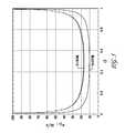
- FIG. 5is a graph illustrating the local sound speed of water as a function of water vapor void fraction in accordance with the heat transfer nozzle of FIG. 3 .
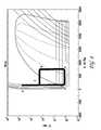
- FIG. 6is a diagram of the void fraction contours and graph of the center line pressure trace down the cooling channel of the heat transfer nozzle of FIG. 3 .
- FIG. 7is a diagram of the velocity contours near the post condensation shock in the heat transfer nozzle of FIG. 3 .
- FIG. 8is a diagram of the void fraction contours near post condensation shock in the heat transfer nozzle of FIG. 3 .
- FIG. 9illustrates a schematic diagram for an air-conditioning system in accordance with one or more embodiments of the present invention.
- FIG. 10is a diagrammatic representation of the air-conditioning system of FIG. 9 .
- FIG. 11 aillustrates a heat transfer nozzle as might be used in the system of FIG. 9 .
- FIG. 11 billustrates a cut-await view of the heat transfer nozzle of FIG. 11 a.
- FIG. 12illustrates a water heating system in accordance with one or more embodiments of the present invention.
- various embodiments of the present inventionmay rely upon cavitation for its refrigeration cycle.
- inertial cavitationbubbles of vapor may form in regions of a flowing liquid where the pressure is reduced below the vapor pressure. This may be especially true where the dynamic pressure is rapidly reduced.
- Cavitationis generally regarded as a problem as it results in turbulence, wasted energy, and a shock wave caused when the bubbles collapse and return to the liquid phase. Cavitation can cause corrosion of mechanical items such as propellers and pipes. Engineers generally go to considerable lengths to avoid or minimize cavitation. In the present context, however, inertial cavitation may be used to provide a refrigeration cycle for use in various HVAC and heat transfer applications. Cavitation may include, but is not limited to, the creation of vapor bubbles within a liquid as a result of reduced pressure regardless of whether said reduction is spontaneous, at a seed particle or at a surface, and therefore is inclusive of nucleation.
- Heat energyis transported by a multi-phase fluid including a liquid and vapor bubbles formed by cavitation when the pressure exerted on a portion of the liquid is reduced.
- the production of vapor from a liquidrequires the input of heat energy. Where vapor bubbles are formed in substantial numbers, energy is initially taken from the liquid with the result that the temperature of the liquid falls. Vapor bubbles formed by cavitation collapse readily when the pressure returns above the vapor pressure of the liquid. Heat energy is released and as a result the temperature of the liquid rises.
- FIG. 3is a cross-section of a heat transfer nozzle 11 .
- Heat transfer nozzle 11 of FIG. 3may be used in a commercial or residential air-conditioning system.
- the converging-diverging nozzle 11 of FIG. 3includes an inlet portion 12 , a throat portion 14 , an expansion portion 16 , an outlet portion 18 , and a fluid pathway 20 .
- the inlet portion 12receives liquid refrigerant from a pumped supply under pressure, typically in the range of 500 kPa to 2000 kPa. Pressures outside this range may be used for specialized applications.
- the liquid refrigerantis then directed into the throat portion 14 via a funnel-like or other converging exit 21 .
- the throat portion 14provides a duct of substantially constant profile (normally circular) through its length through which the liquid refrigerant is forced.
- the expansion portion 16provides an expanding tube-like member wherein the diameter of the fluid pathway 20 progressively increases between the throat portion 14 and the outlet portion 18 .
- the actual profile of the expansion portionmay depend upon the actual refrigerant used.
- the outlet portion 18provides a region where the refrigerant exiting the nozzle can mix with refrigerant at ambient conditions and thereafter be conveyed away.
- the pressure and diameter of the throat orificemay be selected so that the speed of the refrigerant at the entry of the throat orifice is approximately the speed of sound (Mach 1).
- the acceleration of the refrigerantcauses a sudden drop in pressure which results in cavitation and commencing at the boundary between the funnel-like exit 21 of the inlet portion 12 and the entry to the throat orifice 14 , but also being triggered along the wall of the throat orifice.
- Cavitationresults in bubbles containing refrigerant in the vapor phase being present within the fluid, thereby providing a multi-phase fluid.
- the creation of such vapor bubblesrequires the input of energy for the input of latent heat of vaporization and as a result the temperature falls.
- the reduction in pressure together with the multiphase fluidresults in the lowering of the speed of sound with the result that refrigerant exits the throat at supersonic speed of, for example, Mach 1.1 or higher.
- the pressurecontinues at a low level and the fluid expands. As a result of the expansion, the flow accelerates further, reaching a speed in the order of approximately Mach 3 further along the expansion portion.
- thermodynamic performance of the nozzle 11is explained below with reference to FIG. 4 , which is a pressure-enthalpy graph for the heat transfer nozzle of FIG. 3 .
- the diagram of FIG. 4specifically uses water as the refrigerant.
- step 1 to 2 in FIG. 4water at low pressure is compressed to a range of 5 to 20 bar. This may be accomplished with a positive displacement pump.
- the high pressure waterflows through the converging-diverging nozzle 11 .
- the flowbegins to cavitate, resulting in a significant reduction in the localized speed of sound.
- the reduction in the localized sound speedwill change the character of the flow from traditional incompressible flow to a regime more compatible with high speed nozzle flow.
- FIG. 5is a graph illustrating the local sound speed of water as a function of water vapor void fraction in accordance with the heat transfer nozzle of FIG. 3 .
- the sound speedis orders of magnitude smaller in the presence of bubbles/vapor.
- the local sound speed as a function of void fractionis defined by:
- the fluidrapidly accelerates and continues to drop in pressure. As the local static pressure drops, more water vapor is generated from the surrounding liquid. As the fluid passes below the saturation line the cold sink required for the cooling method is generated and the flow is behaving as if it was in an over expanded jet. Once the fluid has picked up sufficient heat, and due to frictional losses, it shocks back to a subsonic condition.
- FIG. 6is a diagram of the void fraction contours and graph of the center line pressure trace down the cooling channel of the heat transfer nozzle of FIG. 3 .
- Fluidenters the upstream converging-diverging nozzle at 10 bar; the pressure at the outlet is 1 bar.
- the fluidaccelerates through the throat and initiates cavitation.
- Post throatthe flow behaves as a supersonic flow due to reduced sound speed and increases in speed and experiences a subsequent further reduction in pressure, resulting in further cooling.
- the fluidcontinues to boil off absorbing heat from the secondary loop, until it reaches the point X at which it shocks back to outlet conditions.
- the fluidshocks back up to the ambient pressure as shown at point X in FIGS. 6 , 7 , and 8 .
- the fluidis then expelled back into the main reservoir.
- This shock methodis predicted by utilizing quasi-one dimensional flow equations with heat and mass transfer.
- the post shock predictionsclearly depict a temperature rise due to heat addition from the heating load, plus the irreversible losses of the pump and friction.
- the hot fluid ejected from the cooling tubesis mixed with the bulk fluid to further minimize vapor volume. An example of this method is shown in FIGS. 7 and 8 .
- FIG. 7is a diagram of the velocity contours near the post condensation shock in the heat transfer nozzle of FIG. 3 .
- the pressure at the inlet of FIG. 7equals 10 bar and the pressure at the reservoir (ambient) equals 1 bar.
- the fluidcontinues to accelerate with increasing cross-sectional area indicating that supersonic flow has been achieved in the post throat region.
- FIG. 8is a diagram of the void fraction contours near post condensation shock in the heat transfer nozzle of FIG. 3 .
- the pressure at the inlet of FIG. 8equals 10 bar and the pressure at the reservoir (ambient) equals 1 bar.
- FIG. 9illustrates a schematic diagram for an air-conditioning system 50 in accordance with one or more embodiments of the present invention; for example, an air-conditioning system, which includes the embodiment of FIG. 3 .
- the air-conditioning system 50includes a positive displacement pump 51 , which pumps refrigerant through line 53 to the heat transfer nozzle 52 (nozzle 11 ).
- a first heat exchanger 54receives heat energy from the region to be cooled and transfers that energy to the nozzle 52 at which it is received by the refrigerant during the time during which the refrigerant is in multi-phase.
- the multi-phase fluid“shocks up” to ambient conditions within the nozzle 52 so that the heat transfer method is completed when the refrigerant leaves the nozzle 52 .
- the heated refrigerantis transferred to a second heat exchanger 56 through a line 55 where the absorbed heat energy is removed.
- the refrigerantis then returned to the pump 51 via line 57 .
- FIG. 10is a diagrammatic representation of the air-conditioning system of FIG. 9 .
- the air-conditioning system 61 as shown in FIG. 10includes a housing 62 .
- the housing 62promotes fluid flow around the housing and, in the presently disclosed embodiment, has a shape that is akin to a pumpkin.
- the pump 51is located inside the housing 62 near the upper central wall.
- the pump 51is driven by a motor 58 , which is outside the housing 62 and connects to the pump 51 by an axle (not shown) and that penetrates the housing 62 via a bearing and seal.
- the air-conditioning system 61is sized to provide cooling greater than can be provided with a single heat exchange nozzle, and therefore cooling is achieved by a plurality of heat exchange nozzles arranged in parallel proximate the central region of the housing 62 . This is an easy and cost effective arrangement due to the relatively small size of the single heat exchange unit. All units are supplied from a manifold fed from the pump.
- the housing 62stores a substantial volume of refrigerant, which may be applicable when water is the refrigerant. As is indicated by arrows 59 , refrigerant exits the nozzles into the refrigerant reservoir and then circulates around the housing 62 . The walls of the housing 62 become at least part of the second heat exchanger to dispel the heat which is absorbed into the refrigerant in the nozzles. Additional external heat exchangers may be added if necessary in the application.
- refrigerant R-134amay be utilized in the system 50 of FIG. 10 .
- the heat transfer nozzle 11 of FIG. 3may be adapted for use with most known refrigerants and it is, therefore, envisioned that there will be applications where other refrigerants will be preferred to water.
- the rate of expansion of the expansion portionmust be selected appropriately for any given refrigerant selection.
- the volumetric expansion of refrigerants such as R-123a and R-134aare considerably less than that of water, and it is therefore necessary to reduce the rate of expansion in the expansion portion.
- the expansion half-angle(the angle between the central axis of the nozzle and the wall of the expansion portion) may be on the order of 1°.
- the half-anglemay be on the order of 5° while, for water, the angle is even larger.
- a nozzle as may be suitable for R-134ais illustrated in FIGS. 11 a and 11 b , which illustrate a heat transfer nozzle and cut-away view, respectively. It may be noted that the size of this angle plays a role in the operation of the heat exchange nozzle.
- FIG. 12is for a water heating system.
- the water heating apparatus 70includes a pump 71 , a bank of nozzles 72 in parallel together with associated heat exchanger 74 , a hot water storage tank 76 , cold water inlet pipe 78 , hot water outlet pipe 79 , a control system (not shown), and circulation piping 73 , 75 , and 77 .
- the water heating apparatus of FIG. 12may be of the “storage” type.
- thermodynamics and mechanics of the present systemscan be further enhanced through application of nanotechnology. This may be especially true in the context of water as a refrigerant. For instance, high heat transfer coefficients in the sonic multiphase cooling regime may be achieved.
- Application of highly conductive nano-particles to the flowmay help increase the effective thermo-conductivity and enhance heat transfer rates. Inclusion of nano-particle agglomerate can have an effect on the cavitation phenomena in the throat.
Landscapes
- Engineering & Computer Science (AREA)
- Physics & Mathematics (AREA)
- Thermal Sciences (AREA)
- Mechanical Engineering (AREA)
- General Engineering & Computer Science (AREA)
- Chemical & Material Sciences (AREA)
- Combustion & Propulsion (AREA)
- Jet Pumps And Other Pumps (AREA)
- Other Air-Conditioning Systems (AREA)
Abstract
Description
Pumppower=Q*ΔP
where Q is the volumetric flow rate and ΔP is the pressure rise across the pump. Since the volumetric flow rate Q for liquid water is orders of magnitude less than the water vapor, significant energy is saved in this phase compared with a vapor compression system.
where c denotes the speed of sound and L and V represent the liquid and vapor phases respectively. Once the flow speed exceeds the local sound speed the downstream pressure conditions cannot propagate upstream. In this condition, the flow now behaves like a supersonic nozzle and the parabolic nature of the governing equations can be taken advantage of in order to drive the saturation temperatures down, thereby providing cooling potential.
Claims (16)
Priority Applications (1)
| Application Number | Priority Date | Filing Date | Title |
|---|---|---|---|
| US12/961,386US8359872B2 (en) | 2009-09-04 | 2010-12-06 | Heating and cooling of working fluids |
Applications Claiming Priority (3)
| Application Number | Priority Date | Filing Date | Title |
|---|---|---|---|
| US24015309P | 2009-09-04 | 2009-09-04 | |
| US12/876,985US8365540B2 (en) | 2009-09-04 | 2010-09-07 | System and method for heat transfer |
| US12/961,386US8359872B2 (en) | 2009-09-04 | 2010-12-06 | Heating and cooling of working fluids |
Related Parent Applications (1)
| Application Number | Title | Priority Date | Filing Date |
|---|---|---|---|
| US12/876,985ContinuationUS8365540B2 (en) | 2009-09-04 | 2010-09-07 | System and method for heat transfer |
Publications (2)
| Publication Number | Publication Date |
|---|---|
| US20110117511A1 US20110117511A1 (en) | 2011-05-19 |
| US8359872B2true US8359872B2 (en) | 2013-01-29 |
Family
ID=44141620
Family Applications (3)
| Application Number | Title | Priority Date | Filing Date |
|---|---|---|---|
| US12/876,985Expired - Fee RelatedUS8365540B2 (en) | 2009-09-04 | 2010-09-07 | System and method for heat transfer |
| US12/961,386Expired - Fee RelatedUS8359872B2 (en) | 2009-09-04 | 2010-12-06 | Heating and cooling of working fluids |
| US12/961,366ActiveUS8887525B2 (en) | 2009-09-04 | 2010-12-06 | Heat exchange and cooling systems |
Family Applications Before (1)
| Application Number | Title | Priority Date | Filing Date |
|---|---|---|---|
| US12/876,985Expired - Fee RelatedUS8365540B2 (en) | 2009-09-04 | 2010-09-07 | System and method for heat transfer |
Family Applications After (1)
| Application Number | Title | Priority Date | Filing Date |
|---|---|---|---|
| US12/961,366ActiveUS8887525B2 (en) | 2009-09-04 | 2010-12-06 | Heat exchange and cooling systems |
Country Status (1)
| Country | Link |
|---|---|
| US (3) | US8365540B2 (en) |
Cited By (2)
| Publication number | Priority date | Publication date | Assignee | Title |
|---|---|---|---|---|
| US20110113792A1 (en)* | 2009-09-04 | 2011-05-19 | Jayden David Harman | Heat Exchange and Cooling Systems |
| US8820114B2 (en) | 2009-03-25 | 2014-09-02 | Pax Scientific, Inc. | Cooling of heat intensive systems |
Families Citing this family (9)
| Publication number | Priority date | Publication date | Assignee | Title |
|---|---|---|---|---|
| DE102008016627A1 (en)* | 2008-04-01 | 2009-10-08 | Efficient Energy Gmbh | Condenser for a heat pump, heat pump and process for producing a condenser |
| US8505322B2 (en)* | 2009-03-25 | 2013-08-13 | Pax Scientific, Inc. | Battery cooling |
| AU2010229821A1 (en) | 2009-03-25 | 2011-11-17 | Caitin, Inc. | Supersonic cooling system |
| US20110048062A1 (en)* | 2009-03-25 | 2011-03-03 | Thomas Gielda | Portable Cooling Unit |
| US20110048048A1 (en)* | 2009-03-25 | 2011-03-03 | Thomas Gielda | Personal Cooling System |
| US20110051549A1 (en)* | 2009-07-25 | 2011-03-03 | Kristian Debus | Nucleation Ring for a Central Insert |
| EP3497382B1 (en)* | 2016-08-09 | 2019-12-25 | Sabanci Üniversitesi | An energy harvesting device |
| US10258741B2 (en) | 2016-12-28 | 2019-04-16 | Cequr Sa | Microfluidic flow restrictor and system |
| CN116343423B (en)* | 2023-03-31 | 2024-12-03 | 深圳职业技术学院 | Fire prevention and control early warning system and method based on multi-source data analysis |
Citations (68)
| Publication number | Priority date | Publication date | Assignee | Title |
|---|---|---|---|---|
| US1860447A (en) | 1928-07-21 | 1932-05-31 | York Ice Machinery Corp | Refrigeration |
| US2928779A (en) | 1954-08-16 | 1960-03-15 | Jordan T Weills | Neutronic reactor construction and operation |
| US3228848A (en) | 1959-10-29 | 1966-01-11 | Socony Mobil Oil Co Inc | Method and contact material for chemical conversion in presence of nuclear fission fragments |
| US3425486A (en) | 1965-10-28 | 1969-02-04 | Aviat Uk | Garments for controlling the temperature of the body |
| US3510266A (en) | 1967-03-29 | 1970-05-05 | Merck & Co Inc | Production of crystals in a fluidized bed with ultrasonic vibrations |
| US3548589A (en) | 1968-01-19 | 1970-12-22 | Atomic Energy Authority Uk | Heat engines |
| US3552120A (en) | 1969-03-05 | 1971-01-05 | Research Corp | Stirling cycle type thermal device |
| US3621667A (en)* | 1969-03-24 | 1971-11-23 | American Gas Ass The | Cooling apparatus and process |
| US3866433A (en) | 1973-09-12 | 1975-02-18 | Jeffreys George C | Auxiliary refrigeration power means |
| US4031712A (en) | 1975-12-04 | 1977-06-28 | The University Of Delaware | Combined absorption and vapor-compression refrigeration system |
| US4044558A (en) | 1974-08-09 | 1977-08-30 | New Process Industries, Inc. | Thermal oscillator |
| US4057962A (en) | 1976-12-06 | 1977-11-15 | Ford Motor Company | Device for decreasing the start-up time for stirling engines |
| US4201263A (en)* | 1978-09-19 | 1980-05-06 | Anderson James H | Refrigerant evaporator |
| US4333796A (en) | 1978-05-19 | 1982-06-08 | Flynn Hugh G | Method of generating energy by acoustically induced cavitation fusion and reactor therefor |
| US4442675A (en) | 1981-05-11 | 1984-04-17 | Soma Kurtis | Method for thermodynamic cycle |
| US4858155A (en) | 1985-12-24 | 1989-08-15 | Beckman Instruments, Inc. | Reaction temperature control system |
| US4998415A (en) | 1989-10-30 | 1991-03-12 | Larsen John D | Body cooling apparatus |
| US5074759A (en) | 1990-03-14 | 1991-12-24 | Cossairt Keith R | Fluid dynamic pump |
| US5083429A (en) | 1988-07-08 | 1992-01-28 | Gergely Veres | Method of and compression tube for increasing pressure of a flowing gaseous medium, and power machine applying the compression tube |
| US5205648A (en) | 1990-09-06 | 1993-04-27 | Transsonic Uberschall-Anlagen Gmbh | Method and device for acting upon fluids by means of a shock wave |
| US5317905A (en) | 1992-10-05 | 1994-06-07 | Johnson H James | Refrigeration system |
| US5338113A (en) | 1990-09-06 | 1994-08-16 | Transsonic Uberschall-Anlagen Gmbh | Method and device for pressure jumps in two-phase mixtures |
| US5353602A (en) | 1993-03-25 | 1994-10-11 | Calmac Manufacturing Corporation | Non-steady-state self-regulating intermittent flow thermodynamic system |
| US5544961A (en) | 1992-02-11 | 1996-08-13 | April Dynamics Industries Ltd. | Two-phase supersonic flow system |
| US5659173A (en) | 1994-02-23 | 1997-08-19 | The Regents Of The University Of California | Converting acoustic energy into useful other energy forms |
| US5810037A (en) | 1994-07-22 | 1998-09-22 | Daido Metal Company Ltd. | Ultrasonic treatment apparatus |
| US6170289B1 (en) | 1999-06-18 | 2001-01-09 | General Electric Company | Noise suppressing refrigeration jumper tube |
| EP1080648A2 (en) | 1999-09-06 | 2001-03-07 | Fisher & Paykel Limited | Personal cooling system |
| JP2002130770A (en) | 2000-10-30 | 2002-05-09 | Mitsubishi Electric Corp | Refrigeration cycle apparatus and control method thereof |
| US20020090047A1 (en) | 1991-10-25 | 2002-07-11 | Roger Stringham | Apparatus for producing ecologically clean energy |
| JP2003021410A (en) | 2001-07-04 | 2003-01-24 | Japan Climate Systems Corp | Vehicle air conditioner |
| JP2003034135A (en) | 2001-07-25 | 2003-02-04 | Japan Climate Systems Corp | Air conditioning system for vehicle |
| US6604376B1 (en) | 1999-01-08 | 2003-08-12 | Victor M. Demarco | Heat pump using treated water effluent |
| US6655165B1 (en) | 2002-12-19 | 2003-12-02 | Nissan Technical Center North America, Inc. | Air conditioner with power recovery device having a sound suppression device |
| US6719817B1 (en) | 2003-06-17 | 2004-04-13 | Daniel J Marin | Cavitation hydrogen generator |
| US6739141B1 (en) | 2003-02-12 | 2004-05-25 | Carrier Corporation | Supercritical pressure regulation of vapor compression system by use of gas cooler fluid pumping device |
| US6835484B2 (en) | 2002-07-09 | 2004-12-28 | General Motors Corporation | Supersonic vapor compression and heat rejection cycle |
| US6889754B2 (en) | 2000-06-30 | 2005-05-10 | Swales & Associates, Inc. | Phase control in the capillary evaporators |
| US20060018420A1 (en) | 1999-11-24 | 2006-01-26 | Impulse Devices, Inc. | Heat exchange system for a cavitation chamber |
| US20060032625A1 (en) | 2002-09-28 | 2006-02-16 | Angelis Walter G | Arrangement and method for removing heat from a component which is to be cooled |
| US7004240B1 (en) | 2002-06-24 | 2006-02-28 | Swales & Associates, Inc. | Heat transport system |
| US20060191049A1 (en) | 2004-05-11 | 2006-08-31 | William Elkins | Wearable personal cooling and hydration system |
| US7131294B2 (en) | 2004-01-13 | 2006-11-07 | Tecumseh Products Company | Method and apparatus for control of carbon dioxide gas cooler pressure by use of a capillary tube |
| US20070028646A1 (en)* | 2005-08-02 | 2007-02-08 | Denso Corporation | Ejector refrigeration cycle |
| US7178353B2 (en) | 2004-02-19 | 2007-02-20 | Advanced Thermal Sciences Corp. | Thermal control system and method |
| US7251889B2 (en) | 2000-06-30 | 2007-08-07 | Swales & Associates, Inc. | Manufacture of a heat transfer system |
| US20070271939A1 (en) | 2003-12-25 | 2007-11-29 | Seft Development Laboratory Co., Ltd. | Air-Conditioning Garment |
| US7381241B2 (en) | 1999-11-24 | 2008-06-03 | Impulse Devices, Inc. | Degassing procedure for a cavitation chamber |
| US7387660B2 (en) | 1999-11-24 | 2008-06-17 | Impulse Devices, Inc., | Degassing procedure for a cavitation chamber |
| US7387093B2 (en) | 2006-10-02 | 2008-06-17 | James Scott Hacsi | Internal combustion engine with sidewall combustion chamber and method |
| US7448790B2 (en) | 1999-11-24 | 2008-11-11 | Impulse Devices, Inc. | Cavitation fluid circulatory system for a cavitation chamber |
| WO2009070728A1 (en) | 2007-11-27 | 2009-06-04 | The Curators Of The University Of Missouri | Thermally driven heat pump for heating and cooling |
| US7549461B2 (en) | 2000-06-30 | 2009-06-23 | Alliant Techsystems Inc. | Thermal management system |
| WO2009123674A2 (en) | 2008-02-28 | 2009-10-08 | Greencentaire, Llc | Cooling unit |
| US20090272128A1 (en) | 2008-05-02 | 2009-11-05 | Kysor Industrial Corporation | Cascade cooling system with intercycle cooling |
| US20090293513A1 (en) | 2008-05-28 | 2009-12-03 | Sullivan Shaun E | Machines and Methods for Removing Water From Air |
| US7654095B2 (en) | 2007-06-06 | 2010-02-02 | Greencentaire, Llc | Energy transfer apparatus and methods |
| US7656808B2 (en) | 2003-01-15 | 2010-02-02 | At&T Intellectual Property I, Lp | Web based capacity management (WBCM) system |
| WO2010042467A2 (en) | 2008-10-10 | 2010-04-15 | Spin Energy Corporation | Power-generator fan apparatus, duct assembly, building construction, and methods of use |
| US7708053B2 (en) | 2000-06-30 | 2010-05-04 | Alliant Techsystems Inc. | Heat transfer system |
| US20100126212A1 (en) | 2008-08-14 | 2010-05-27 | May Wayne A | Binary fluid ejector and method of use |
| US7796389B2 (en) | 2008-11-26 | 2010-09-14 | General Electric Company | Method and apparatus for cooling electronics |
| US20100287954A1 (en) | 2009-03-25 | 2010-11-18 | Jayden Harman | Supersonic Cooling System |
| US20110030390A1 (en) | 2009-04-02 | 2011-02-10 | Serguei Charamko | Vortex Tube |
| US20110048048A1 (en) | 2009-03-25 | 2011-03-03 | Thomas Gielda | Personal Cooling System |
| US20110048062A1 (en) | 2009-03-25 | 2011-03-03 | Thomas Gielda | Portable Cooling Unit |
| US20110051549A1 (en) | 2009-07-25 | 2011-03-03 | Kristian Debus | Nucleation Ring for a Central Insert |
| US20110048066A1 (en) | 2009-03-25 | 2011-03-03 | Thomas Gielda | Battery Cooling |
Family Cites Families (71)
| Publication number | Priority date | Publication date | Assignee | Title |
|---|---|---|---|---|
| US442675A (en)* | 1890-12-16 | Curtis n | ||
| US2116480A (en)* | 1936-01-17 | 1938-05-03 | Climax Machinery Company | Method and apparatus for conditioning air |
| US2518202A (en)* | 1944-10-25 | 1950-08-08 | Servel Inc | Vacuum type water absorption refrigerating system |
| US2905731A (en) | 1955-07-25 | 1959-09-22 | Phillips Petroleum Co | Hydrocarbon conversion method |
| US4070131A (en)* | 1975-01-20 | 1978-01-24 | Grumman Aerospace Corporation | Tornado-type wind turbine |
| US4089187A (en)* | 1975-06-23 | 1978-05-16 | General Electric Company | Condenser-air flow system of a household refrigerator |
| US4043769A (en)* | 1975-12-15 | 1977-08-23 | Mitsubishi Jukogyo Kabuskiki Kaisha | Process for recovering a solvent vapor |
| US4440675A (en)* | 1981-08-18 | 1984-04-03 | Meloy Laboratories, Inc. | Human immune interferon |
| US4499034A (en)* | 1982-09-02 | 1985-02-12 | The United States Of America As Represented By The United States Department Of Energy | Vortex-augmented cooling tower-windmill combination |
| JPS60175980U (en) | 1984-04-27 | 1985-11-21 | 昭和電線電纜株式会社 | Conduit mouth waterproofing device |
| SU1312348A1 (en) | 1985-08-19 | 1987-05-23 | Всесоюзный заочный машиностроительный институт | Cryogenic unit ejector stage |
| US4859347A (en)* | 1988-11-18 | 1989-08-22 | Simon Wayne E | Centrifugal separator |
| US5439560A (en)* | 1990-02-22 | 1995-08-08 | Konica Corporation | Low pressure evaporation concentrating apparatus for a photographic process waste disposl |
| US5770019A (en)* | 1991-01-31 | 1998-06-23 | Konica Corporation | Apparatus for concentrating waste liquid |
| JP3411280B2 (en) | 1992-09-21 | 2003-05-26 | 協和醗酵工業株式会社 | Antithrombotic agent |
| US5343711A (en)* | 1993-01-04 | 1994-09-06 | Virginia Tech Intellectual Properties, Inc. | Method of reducing flow metastability in an ejector nozzle |
| US5431346A (en)* | 1993-07-20 | 1995-07-11 | Sinaisky; Nickoli | Nozzle including a venturi tube creating external cavitation collapse for atomization |
| US5467613A (en) | 1994-04-05 | 1995-11-21 | Carrier Corporation | Two phase flow turbine |
| CR5278A (en)* | 1995-03-24 | 1996-07-04 | Lilly Co Eli | ORAL FORMULATION OF 2-METHYL-THENO-BENZODIACEPINE |
| US5647221A (en)* | 1995-10-10 | 1997-07-15 | The George Washington University | Pressure exchanging ejector and refrigeration apparatus and method |
| US6241160B1 (en)* | 1996-03-21 | 2001-06-05 | Daniel S. Redford | Atmospheric inversion layer de-stabilizer apparatus |
| RU2113634C1 (en)* | 1997-04-21 | 1998-06-20 | Сергей Анатольевич Попов | Method of operation of pump ejector plant for distillation of liquid product |
| RU2114893C1 (en)* | 1997-09-04 | 1998-07-10 | Сергей Анатольевич Попов | Method and installation for distilling multicomponent mixture |
| US6190498B1 (en) | 1999-02-01 | 2001-02-20 | Slimline Mfg. Ltd. | Evaporator |
| US6105382A (en)* | 1999-03-29 | 2000-08-22 | The United States Of America As Represented By The Secretary Of The Navy | Chest mounted armored microclimate conditioned air device |
| DE10009164C1 (en)* | 2000-02-26 | 2001-07-19 | Festo Ag & Co | Combined vacuum generator units has housing of each unit provided with ejector socket for fitting with ejector inserts of varying type |
| US6430937B2 (en) | 2000-03-03 | 2002-08-13 | Vai Holdings, Llc | Vortex generator to recover performance loss of a refrigeration system |
| US6796704B1 (en) | 2000-06-06 | 2004-09-28 | W. Gerald Lott | Apparatus and method for mixing components with a venturi arrangement |
| US20020177035A1 (en) | 2001-05-23 | 2002-11-28 | Alcatel | Thermal management blanketing and jacketing for battery system modules |
| US7086823B2 (en)* | 2001-09-19 | 2006-08-08 | Louis M Michaud | Atmospheric vortex engine |
| US20030085296A1 (en)* | 2001-11-02 | 2003-05-08 | Andrew Waxmanski | Hurricane and tornado control device |
| JP3945252B2 (en)* | 2002-01-10 | 2007-07-18 | 株式会社デンソー | Gas-liquid separator for ejector cycle |
| CA2473792C (en)* | 2002-01-29 | 2010-11-30 | Telefonaktiebolaget L M Ericsson (Publ) | A method and system of cooling a cabinet using dynamically controlled ciculating cooling fluid |
| US7146822B2 (en)* | 2002-12-30 | 2006-12-12 | Intel Corporation | Centrifugal liquid pump with perimeter magnetic drive |
| US20050039626A1 (en)* | 2003-02-03 | 2005-02-24 | Henry Yi | Dynamic tornado teardown system |
| JP4232484B2 (en)* | 2003-03-05 | 2009-03-04 | 株式会社日本自動車部品総合研究所 | Ejector and vapor compression refrigerator |
| US20040267272A1 (en)* | 2003-05-12 | 2004-12-30 | Henniges Bruce D | Bone cement mixing and delivery system |
| US6865897B2 (en)* | 2003-07-10 | 2005-03-15 | Praxair Technology, Inc. | Method for providing refrigeration using capillary pumped liquid |
| US7938615B2 (en)* | 2003-09-11 | 2011-05-10 | Louis Michaud | Enhanced vortex engine |
| JP4565859B2 (en) | 2004-02-26 | 2010-10-20 | 樫山工業株式会社 | pump |
| US7442919B2 (en) | 2004-02-27 | 2008-10-28 | Japan Science And Technology Agency | Supercritical fluid jet method and supercritical fluid jet mass analysis method and device |
| EP2302172A1 (en) | 2004-11-12 | 2011-03-30 | Board of Trustees of Michigan State University | Machine comprising an electromagnetic woven rotor and manufacturing method |
| JP2006141546A (en) | 2004-11-17 | 2006-06-08 | Sanyo Electric Co Ltd | Distillation apparatus for dry cleaner |
| JP4691981B2 (en)* | 2004-12-14 | 2011-06-01 | パナソニック株式会社 | Battery pack |
| US20070010339A1 (en)* | 2005-06-21 | 2007-01-11 | Stone Ben C | Amusement device with vortex airflow |
| DE102005035754A1 (en)* | 2005-07-29 | 2007-02-08 | Amphenol-Tuchel-Electronics Gmbh | Method for contacting partially conductive semi-finished textile products |
| US8001794B2 (en)* | 2006-02-27 | 2011-08-23 | Action Circuit Productions, Inc. | Thermoelectric fluid heat exchange system |
| WO2007130377A2 (en)* | 2006-05-05 | 2007-11-15 | Separation Design Group, Llc | Sorption method, device, and system |
| US7735334B2 (en)* | 2006-07-06 | 2010-06-15 | Mark Johnson | Portable cooler |
| JP4929936B2 (en)* | 2006-09-07 | 2012-05-09 | 株式会社デンソー | Ejector and ejector refrigeration cycle |
| CA2560814C (en)* | 2006-09-25 | 2014-08-26 | Transcanada Pipelines Limited | Tandem supersonic ejectors |
| US20080292948A1 (en) | 2007-05-23 | 2008-11-27 | Ajith Kuttannair Kumar | Battery cooling system and methods of cooling |
| US9207023B2 (en)* | 2007-12-18 | 2015-12-08 | Sandia Corporation | Heat exchanger device and method for heat removal or transfer |
| JP4760843B2 (en) | 2008-03-13 | 2011-08-31 | 株式会社デンソー | Ejector device and vapor compression refrigeration cycle using ejector device |
| US20090266516A1 (en) | 2008-04-28 | 2009-10-29 | University Of Washington | Electrospray Evaporative Cooling (ESC) |
| US8087880B2 (en)* | 2008-12-03 | 2012-01-03 | General Electric Company | Active clearance control for a centrifugal compressor |
| US8578733B2 (en)* | 2009-01-21 | 2013-11-12 | Appollo Wind Technologies Llc | Turbo-compressor-condenser-expander |
| US20120205080A1 (en)* | 2011-02-15 | 2012-08-16 | Kristian Debus | Pump-Less Cooling Using a Rotating Disk |
| US8820114B2 (en)* | 2009-03-25 | 2014-09-02 | Pax Scientific, Inc. | Cooling of heat intensive systems |
| US20120118538A1 (en)* | 2010-11-12 | 2012-05-17 | Thomas Gielda | Pump-Less Cooling |
| US8365540B2 (en)* | 2009-09-04 | 2013-02-05 | Pax Scientific, Inc. | System and method for heat transfer |
| WO2011119338A1 (en) | 2010-03-25 | 2011-09-29 | Caitin, Inc. | Cooling systems utilizing a supersonic cooling cycle |
| MX2012011568A (en)* | 2010-04-09 | 2012-11-16 | Abaridy Pty Ltd | Vapour absorption system. |
| US20120297800A1 (en) | 2011-05-23 | 2012-11-29 | Kristian Debus | Supersonic Cooling Nozzle Inlet |
| WO2012018627A1 (en) | 2010-07-26 | 2012-02-09 | Caitin Inc. | Supersonic cooling nozzle inlet |
| US20120285661A1 (en) | 2011-01-14 | 2012-11-15 | Caitin, Inc. | Vapor absorption system |
| US20120260673A1 (en) | 2011-04-14 | 2012-10-18 | Serguei Charamko | Cooling system utilizing a reciprocating piston |
| US20120260676A1 (en) | 2011-04-18 | 2012-10-18 | Serguei Charamko | Cooling system utilizing a conical body |
| US20120301268A1 (en) | 2011-05-25 | 2012-11-29 | Tom Gielda | Supersonic Cooling With Pulsed Inlet and Bypass Loop |
| WO2013070254A1 (en) | 2011-11-09 | 2013-05-16 | Jayden Harman | Atmospheric circulation system and method |
| WO2014058417A1 (en) | 2012-10-09 | 2014-04-17 | Abaridy Pty. Ltd. | Vapor absorption system |
- 2010
- 2010-09-07USUS12/876,985patent/US8365540B2/ennot_activeExpired - Fee Related
- 2010-12-06USUS12/961,386patent/US8359872B2/ennot_activeExpired - Fee Related
- 2010-12-06USUS12/961,366patent/US8887525B2/enactiveActive
Patent Citations (81)
| Publication number | Priority date | Publication date | Assignee | Title |
|---|---|---|---|---|
| US1860447A (en) | 1928-07-21 | 1932-05-31 | York Ice Machinery Corp | Refrigeration |
| US2928779A (en) | 1954-08-16 | 1960-03-15 | Jordan T Weills | Neutronic reactor construction and operation |
| US3228848A (en) | 1959-10-29 | 1966-01-11 | Socony Mobil Oil Co Inc | Method and contact material for chemical conversion in presence of nuclear fission fragments |
| US3425486A (en) | 1965-10-28 | 1969-02-04 | Aviat Uk | Garments for controlling the temperature of the body |
| US3510266A (en) | 1967-03-29 | 1970-05-05 | Merck & Co Inc | Production of crystals in a fluidized bed with ultrasonic vibrations |
| US3548589A (en) | 1968-01-19 | 1970-12-22 | Atomic Energy Authority Uk | Heat engines |
| US3552120A (en) | 1969-03-05 | 1971-01-05 | Research Corp | Stirling cycle type thermal device |
| US3621667A (en)* | 1969-03-24 | 1971-11-23 | American Gas Ass The | Cooling apparatus and process |
| US3866433A (en) | 1973-09-12 | 1975-02-18 | Jeffreys George C | Auxiliary refrigeration power means |
| US4044558A (en) | 1974-08-09 | 1977-08-30 | New Process Industries, Inc. | Thermal oscillator |
| US4031712A (en) | 1975-12-04 | 1977-06-28 | The University Of Delaware | Combined absorption and vapor-compression refrigeration system |
| US4057962A (en) | 1976-12-06 | 1977-11-15 | Ford Motor Company | Device for decreasing the start-up time for stirling engines |
| US4333796A (en) | 1978-05-19 | 1982-06-08 | Flynn Hugh G | Method of generating energy by acoustically induced cavitation fusion and reactor therefor |
| US4201263A (en)* | 1978-09-19 | 1980-05-06 | Anderson James H | Refrigerant evaporator |
| US4442675A (en) | 1981-05-11 | 1984-04-17 | Soma Kurtis | Method for thermodynamic cycle |
| US4858155A (en) | 1985-12-24 | 1989-08-15 | Beckman Instruments, Inc. | Reaction temperature control system |
| US5083429A (en) | 1988-07-08 | 1992-01-28 | Gergely Veres | Method of and compression tube for increasing pressure of a flowing gaseous medium, and power machine applying the compression tube |
| US4998415A (en) | 1989-10-30 | 1991-03-12 | Larsen John D | Body cooling apparatus |
| US5074759A (en) | 1990-03-14 | 1991-12-24 | Cossairt Keith R | Fluid dynamic pump |
| US5205648A (en) | 1990-09-06 | 1993-04-27 | Transsonic Uberschall-Anlagen Gmbh | Method and device for acting upon fluids by means of a shock wave |
| US5275486A (en) | 1990-09-06 | 1994-01-04 | Transsonic Uberschall-Anlagen Gmbh | Device for acting upon fluids by means of a shock wave |
| US5338113A (en) | 1990-09-06 | 1994-08-16 | Transsonic Uberschall-Anlagen Gmbh | Method and device for pressure jumps in two-phase mixtures |
| US20020090047A1 (en) | 1991-10-25 | 2002-07-11 | Roger Stringham | Apparatus for producing ecologically clean energy |
| US5544961A (en) | 1992-02-11 | 1996-08-13 | April Dynamics Industries Ltd. | Two-phase supersonic flow system |
| US5317905A (en) | 1992-10-05 | 1994-06-07 | Johnson H James | Refrigeration system |
| US5353602A (en) | 1993-03-25 | 1994-10-11 | Calmac Manufacturing Corporation | Non-steady-state self-regulating intermittent flow thermodynamic system |
| US5659173A (en) | 1994-02-23 | 1997-08-19 | The Regents Of The University Of California | Converting acoustic energy into useful other energy forms |
| US5810037A (en) | 1994-07-22 | 1998-09-22 | Daido Metal Company Ltd. | Ultrasonic treatment apparatus |
| US6604376B1 (en) | 1999-01-08 | 2003-08-12 | Victor M. Demarco | Heat pump using treated water effluent |
| US6170289B1 (en) | 1999-06-18 | 2001-01-09 | General Electric Company | Noise suppressing refrigeration jumper tube |
| EP1080648A2 (en) | 1999-09-06 | 2001-03-07 | Fisher & Paykel Limited | Personal cooling system |
| US7448790B2 (en) | 1999-11-24 | 2008-11-11 | Impulse Devices, Inc. | Cavitation fluid circulatory system for a cavitation chamber |
| US7387660B2 (en) | 1999-11-24 | 2008-06-17 | Impulse Devices, Inc., | Degassing procedure for a cavitation chamber |
| US7381241B2 (en) | 1999-11-24 | 2008-06-03 | Impulse Devices, Inc. | Degassing procedure for a cavitation chamber |
| US20060018419A1 (en) | 1999-11-24 | 2006-01-26 | Impulse Devices, Inc. | Heat exchange system for a cavitation chamber |
| US20060018420A1 (en) | 1999-11-24 | 2006-01-26 | Impulse Devices, Inc. | Heat exchange system for a cavitation chamber |
| US6889754B2 (en) | 2000-06-30 | 2005-05-10 | Swales & Associates, Inc. | Phase control in the capillary evaporators |
| US7549461B2 (en) | 2000-06-30 | 2009-06-23 | Alliant Techsystems Inc. | Thermal management system |
| US7708053B2 (en) | 2000-06-30 | 2010-05-04 | Alliant Techsystems Inc. | Heat transfer system |
| US7251889B2 (en) | 2000-06-30 | 2007-08-07 | Swales & Associates, Inc. | Manufacture of a heat transfer system |
| JP2002130770A (en) | 2000-10-30 | 2002-05-09 | Mitsubishi Electric Corp | Refrigeration cycle apparatus and control method thereof |
| JP2003021410A (en) | 2001-07-04 | 2003-01-24 | Japan Climate Systems Corp | Vehicle air conditioner |
| JP2003034135A (en) | 2001-07-25 | 2003-02-04 | Japan Climate Systems Corp | Air conditioning system for vehicle |
| US7004240B1 (en) | 2002-06-24 | 2006-02-28 | Swales & Associates, Inc. | Heat transport system |
| US20080277098A1 (en) | 2002-07-09 | 2008-11-13 | General Motors Corporation | Supersonic vapor compression and heat rejection cycle |
| US6835484B2 (en) | 2002-07-09 | 2004-12-28 | General Motors Corporation | Supersonic vapor compression and heat rejection cycle |
| US20050048339A1 (en) | 2002-07-09 | 2005-03-03 | Fly Gerald W. | Supersonic vapor compression and heat rejection cycle |
| US7399545B2 (en) | 2002-07-09 | 2008-07-15 | General Motors Corporation | Supersonic vapor compression and heat rejection cycle |
| US20060032625A1 (en) | 2002-09-28 | 2006-02-16 | Angelis Walter G | Arrangement and method for removing heat from a component which is to be cooled |
| US6655165B1 (en) | 2002-12-19 | 2003-12-02 | Nissan Technical Center North America, Inc. | Air conditioner with power recovery device having a sound suppression device |
| US7656808B2 (en) | 2003-01-15 | 2010-02-02 | At&T Intellectual Property I, Lp | Web based capacity management (WBCM) system |
| US6739141B1 (en) | 2003-02-12 | 2004-05-25 | Carrier Corporation | Supercritical pressure regulation of vapor compression system by use of gas cooler fluid pumping device |
| WO2004072567A2 (en) | 2003-02-12 | 2004-08-26 | Carrier Corporation | Supercritical pressure regulation of vapor compression system |
| US6719817B1 (en) | 2003-06-17 | 2004-04-13 | Daniel J Marin | Cavitation hydrogen generator |
| US20070271939A1 (en) | 2003-12-25 | 2007-11-29 | Seft Development Laboratory Co., Ltd. | Air-Conditioning Garment |
| US7721569B2 (en) | 2004-01-13 | 2010-05-25 | Tecumseh Products Company | Method and apparatus for control of carbon dioxide gas cooler pressure by use of a capillary tube |
| US7131294B2 (en) | 2004-01-13 | 2006-11-07 | Tecumseh Products Company | Method and apparatus for control of carbon dioxide gas cooler pressure by use of a capillary tube |
| US7415835B2 (en) | 2004-02-19 | 2008-08-26 | Advanced Thermal Sciences Corp. | Thermal control system and method |
| US7765820B2 (en) | 2004-02-19 | 2010-08-03 | Advanced Thermal Sciences, Corp. | Thermal control system and method |
| US7178353B2 (en) | 2004-02-19 | 2007-02-20 | Advanced Thermal Sciences Corp. | Thermal control system and method |
| US20060191049A1 (en) | 2004-05-11 | 2006-08-31 | William Elkins | Wearable personal cooling and hydration system |
| WO2006137850A2 (en) | 2004-10-07 | 2006-12-28 | Impulse Devices, Inc. | Heat exchange system for use with a cavitation system |
| US20070028646A1 (en)* | 2005-08-02 | 2007-02-08 | Denso Corporation | Ejector refrigeration cycle |
| US7387093B2 (en) | 2006-10-02 | 2008-06-17 | James Scott Hacsi | Internal combustion engine with sidewall combustion chamber and method |
| US7726135B2 (en) | 2007-06-06 | 2010-06-01 | Greencentaire, Llc | Energy transfer apparatus and methods |
| US7654095B2 (en) | 2007-06-06 | 2010-02-02 | Greencentaire, Llc | Energy transfer apparatus and methods |
| WO2009070728A1 (en) | 2007-11-27 | 2009-06-04 | The Curators Of The University Of Missouri | Thermally driven heat pump for heating and cooling |
| WO2009123674A2 (en) | 2008-02-28 | 2009-10-08 | Greencentaire, Llc | Cooling unit |
| US20100154445A1 (en) | 2008-02-28 | 2010-06-24 | Sullivan Shaun E | Cooling unit |
| US20090272128A1 (en) | 2008-05-02 | 2009-11-05 | Kysor Industrial Corporation | Cascade cooling system with intercycle cooling |
| US20090293513A1 (en) | 2008-05-28 | 2009-12-03 | Sullivan Shaun E | Machines and Methods for Removing Water From Air |
| US20100126212A1 (en) | 2008-08-14 | 2010-05-27 | May Wayne A | Binary fluid ejector and method of use |
| US20100090469A1 (en) | 2008-10-10 | 2010-04-15 | Sullivan Shaun E | Power-Generator Fan Apparatus, Duct Assembly, Building Construction, and Methods of Use |
| WO2010042467A2 (en) | 2008-10-10 | 2010-04-15 | Spin Energy Corporation | Power-generator fan apparatus, duct assembly, building construction, and methods of use |
| US7796389B2 (en) | 2008-11-26 | 2010-09-14 | General Electric Company | Method and apparatus for cooling electronics |
| US20100287954A1 (en) | 2009-03-25 | 2010-11-18 | Jayden Harman | Supersonic Cooling System |
| US20110048048A1 (en) | 2009-03-25 | 2011-03-03 | Thomas Gielda | Personal Cooling System |
| US20110048062A1 (en) | 2009-03-25 | 2011-03-03 | Thomas Gielda | Portable Cooling Unit |
| US20110048066A1 (en) | 2009-03-25 | 2011-03-03 | Thomas Gielda | Battery Cooling |
| US20110030390A1 (en) | 2009-04-02 | 2011-02-10 | Serguei Charamko | Vortex Tube |
| US20110051549A1 (en) | 2009-07-25 | 2011-03-03 | Kristian Debus | Nucleation Ring for a Central Insert |
Non-Patent Citations (29)
| Title |
|---|
| "Nozzle Applet" Published by Virginia Polytechnic Institute and State University (Virginia Tech) and retrieved on May 10, 2011 at http://www.engapplets.vt.edu/fluids/CDnozzle/cdinfo.html. |
| Combined search and examination report mailed Jan. 21, 2011 in U.K. patent application No. GB1021925.1. |
| Energy Efficiency Manual, "Compression Cooling," D.R. Wulfinghoff, 1999, pp. 1299-1321. |
| Final Office Action mailed May 17, 2011 in U.S. Appl. No. 12/961,341, filed Dec. 6, 2010. |
| Final Office Action mailed May 17, 2011 in U.S. Appl. No. 12/961,342, filed Dec. 6, 2010. |
| Final Office Action mailed May 19, 2011 in U.S. Appl. No. 12/960,979, filed Dec. 6, 2010. |
| Fox, et al., "Supersonic Cooling by Shock-Vortex Interaction," J. Fluid Mech. 1996, vol. 308, pp. 363-379. |
| Hu, et al., "Numerical and Experimental Study of a Hydrodynamic Cavitation Tube," Metallurgical and Materials Transactions B, vol. 29B, Aug. 1998. |
| International Preliminary Report on Patentability mailed on Aug. 19, 2011 in Patent Cooperation Treaty application No. PCT/US2010/028761 filed Mar. 25, 2010. |
| International Search Report mailed Jul. 25, 2011 in Patent Cooperation Treaty application No. PCT/US2011/027845 filed Mar. 10, 2011. |
| Interview Summary mailed Jul. 13, 2011 in U.S. Appl. No. 12/961,342, filed Dec. 6, 2010. |
| Interview Summary mailed Mar. 10, 2011 in U.S. Appl. No. 12/961,015, filed Dec. 6, 2010. |
| Interview Summary mailed Mar. 16, 2011 in U.S. Appl. No. 12/960,979, filed Dec. 6, 2010. |
| Interview Summary mailed Mar. 18, 2011 in U.S. Appl. No. 12/961,342, filed Dec. 6, 2010. |
| M.Guglielmone et al., Heat Recovery from Vapor Compression Air Conditioning: A Brief Introduction, Turbotec Products, Inc., May 14, 2008. |
| Mishra, et al., "Development of Cavitation in Refrigerant (R-123) Flow Inside Rudimentary Microfluidic Systems," Journal of Microelectromechanical Systems, vol. 15, No. 5, Oct. 2006. |
| NASA Tech Briefs, "Vapor-Compression Solar Refrigerator Without Batteries," Sep. 2001, http://www.techbriefs.com/component/content/article/7426. |
| Non-final office action mailed Feb. 1, 2011 in U.S. Appl. No. 12/961,342. |
| Non-final office action mailed Feb. 16, 2011 in U.S. Appl. No. 12/961,015. |
| Non-final office action mailed Feb. 4, 2011 in U.S. Appl. No. 12/960,979. |
| PCT Application No. PCT/US2010/28761, International Preliminary Report on Patentability mailed Aug. 19, 2011, 5pgs. |
| Robert H. Turner, Water Consumption of Evaporative Cooling Systems,'21st Intersociety Energy Conservation Engineering Conference, San Diego, California, Aug. 25-29, 1986. |
| S. Klein et al., "Solar Refrigeration," American Society of Heating, Refrigerating and Conditioning Engineers, Inc., Ashrae Journal, vol. 47 No. 9, Sep. 2005. |
| U.S. Appl. No. 13/048,633, filed Mar. 15, 2011, David Halt, Supersonic Cooling Nozzle With Airfoils. |
| U.S. Appl. No. 13/087,062, filed Apr. 14, 2011, Serguei Charamko, Cooling System Utilizing a Reciprocating Piston. |
| U.S. Appl. No. 13/088,593, filed Apr. 18, 2011, Serguei Charamko, Cooling System Utilizing a Conical Body. |
| U.S. Appl. No. 13/113,626, filed May 23, 2011, Kristian Debus et al., Supersonic Cooling Nozzle Inlet. |
| U.S. Appl. No. 13/115,930, filed May 25, 2011, Tom Gielda, Supersonic Cooling with Pulsed Inlet and Bypass Loop. |
| Wikipedia, "Stirling engine," http://en.wikipedia.org/wiki/Stirling-engine, visited May 3, 2010. |
Cited By (3)
| Publication number | Priority date | Publication date | Assignee | Title |
|---|---|---|---|---|
| US8820114B2 (en) | 2009-03-25 | 2014-09-02 | Pax Scientific, Inc. | Cooling of heat intensive systems |
| US20110113792A1 (en)* | 2009-09-04 | 2011-05-19 | Jayden David Harman | Heat Exchange and Cooling Systems |
| US8887525B2 (en) | 2009-09-04 | 2014-11-18 | Pax Scientific, Inc. | Heat exchange and cooling systems |
Also Published As
| Publication number | Publication date |
|---|---|
| US20110139405A1 (en) | 2011-06-16 |
| US8887525B2 (en) | 2014-11-18 |
| US20110113792A1 (en) | 2011-05-19 |
| US8365540B2 (en) | 2013-02-05 |
| US20110117511A1 (en) | 2011-05-19 |
Similar Documents
| Publication | Publication Date | Title |
|---|---|---|
| US8359872B2 (en) | Heating and cooling of working fluids | |
| Śmierciew et al. | Experimental investigations of solar driven ejector air-conditioning system | |
| US5309736A (en) | Hydrocarbon fluid, ejector refrigeration system | |
| US6477857B2 (en) | Ejector cycle system with critical refrigerant pressure | |
| JP5083346B2 (en) | Ejector | |
| Li et al. | Analysis on performance characteristics of ejector with variable area-ratio for multi-evaporator refrigeration system based on experimental data | |
| US20120312379A1 (en) | Heating and cooling systems and methods | |
| US10132526B2 (en) | Ejector refrigeration cycle | |
| Ruangtrakoon et al. | An experimental investigation to determine the optimal heat source temperature for R141b ejector operation in refrigeration cycle | |
| Zhu et al. | Experimental investigation and theoretical analysis of oil circulation rates in ejector cooling cycles | |
| Thongtip et al. | An alternative analysis applied to investigate the ejector performance used in R141b jet-pump refrigeration system | |
| Cui et al. | Performance assessment of an ejector enhanced dual temperature refrigeration cycle for domestic refrigerator application | |
| CN100467982C (en) | Vapor compression system and method of sizing a vapor compression system reservoir | |
| US5239837A (en) | Hydrocarbon fluid, ejector refrigeration system | |
| Bencharif et al. | The benefit of droplet injection on the performance of an ejector refrigeration cycle working with R245fa | |
| Zhu et al. | Experimental investigation into the influence of vortex control on transcritical R744 ejector and cycle performance | |
| JP2000055488A (en) | Refrigerating device | |
| Li et al. | Performance analysis of auxiliary entrainment ejector used in multi-evaporator refrigeration system | |
| JP2005024210A (en) | Vapor compression type refrigerating machine | |
| JP2006017444A (en) | Ejector cycle and its control method | |
| JP2009162116A (en) | Ejector and refrigeration cycle apparatus using the same | |
| US20120301268A1 (en) | Supersonic Cooling With Pulsed Inlet and Bypass Loop | |
| JP4666078B2 (en) | Ejector | |
| Agrawal et al. | Performance evaluation of a non-adiabatic capillary tube in a transcritical CO2 heat pump cycle | |
| JP2009300028A (en) | Ejector type refrigerating cycle |
Legal Events
| Date | Code | Title | Description |
|---|---|---|---|
| AS | Assignment | Owner name:CAITIN, INC., CALIFORNIA Free format text:ASSIGNMENT OF ASSIGNORS INTEREST;ASSIGNORS:HARMAN, JAYDEN DAVID;GIELDA, THOMAS;REEL/FRAME:025507/0826 Effective date:20101108 | |
| AS | Assignment | Owner name:CAITIN, INC. F/K/A NEW PAX, INC., CALIFORNIA Free format text:CONFIRMATORY PATENT ASSIGNMENT;ASSIGNOR:SONOMA COOL, INC. F/K/A PAX STREAMLINE, INC.;REEL/FRAME:025630/0637 Effective date:20110113 | |
| AS | Assignment | Owner name:IMPULSE DEVICES INC., CALIFORNIA Free format text:WRITE OF ATTACHMENT;ASSIGNOR:SUPERIOR COURT, ALAMEDA COUNTY OF CALIFORNIA;REEL/FRAME:028314/0886 Effective date:20120525 | |
| AS | Assignment | Owner name:PAX SCIENTIFIC, INC., CALIFORNIA Free format text:ASSIGNMENT OF ASSIGNORS INTEREST;ASSIGNOR:CAITIN, INC.;REEL/FRAME:028496/0584 Effective date:20120418 | |
| STCF | Information on status: patent grant | Free format text:PATENTED CASE | |
| REMI | Maintenance fee reminder mailed | ||
| FPAY | Fee payment | Year of fee payment:4 | |
| SULP | Surcharge for late payment | ||
| FEPP | Fee payment procedure | Free format text:MAINTENANCE FEE REMINDER MAILED (ORIGINAL EVENT CODE: REM.); ENTITY STATUS OF PATENT OWNER: SMALL ENTITY | |
| FEPP | Fee payment procedure | Free format text:7.5 YR SURCHARGE - LATE PMT W/IN 6 MO, SMALL ENTITY (ORIGINAL EVENT CODE: M2555); ENTITY STATUS OF PATENT OWNER: SMALL ENTITY | |
| MAFP | Maintenance fee payment | Free format text:PAYMENT OF MAINTENANCE FEE, 8TH YR, SMALL ENTITY (ORIGINAL EVENT CODE: M2552); ENTITY STATUS OF PATENT OWNER: SMALL ENTITY Year of fee payment:8 | |
| FEPP | Fee payment procedure | Free format text:MAINTENANCE FEE REMINDER MAILED (ORIGINAL EVENT CODE: REM.); ENTITY STATUS OF PATENT OWNER: SMALL ENTITY | |
| LAPS | Lapse for failure to pay maintenance fees | Free format text:PATENT EXPIRED FOR FAILURE TO PAY MAINTENANCE FEES (ORIGINAL EVENT CODE: EXP.); ENTITY STATUS OF PATENT OWNER: SMALL ENTITY | |
| STCH | Information on status: patent discontinuation | Free format text:PATENT EXPIRED DUE TO NONPAYMENT OF MAINTENANCE FEES UNDER 37 CFR 1.362 | |
| FP | Lapsed due to failure to pay maintenance fee | Effective date:20250129 |