US8359721B2 - Sliding split-sleeve implant compressor - Google Patents
Sliding split-sleeve implant compressorDownload PDFInfo
- Publication number
- US8359721B2 US8359721B2US12/204,376US20437608AUS8359721B2US 8359721 B2US8359721 B2US 8359721B2US 20437608 AUS20437608 AUS 20437608AUS 8359721 B2US8359721 B2US 8359721B2
- Authority
- US
- United States
- Prior art keywords
- introducer
- stent
- sleeve
- compressor
- lumen
- Prior art date
- Legal status (The legal status is an assumption and is not a legal conclusion. Google has not performed a legal analysis and makes no representation as to the accuracy of the status listed.)
- Active, expires
Links
Images


Classifications
- A—HUMAN NECESSITIES
- A61—MEDICAL OR VETERINARY SCIENCE; HYGIENE
- A61F—FILTERS IMPLANTABLE INTO BLOOD VESSELS; PROSTHESES; DEVICES PROVIDING PATENCY TO, OR PREVENTING COLLAPSING OF, TUBULAR STRUCTURES OF THE BODY, e.g. STENTS; ORTHOPAEDIC, NURSING OR CONTRACEPTIVE DEVICES; FOMENTATION; TREATMENT OR PROTECTION OF EYES OR EARS; BANDAGES, DRESSINGS OR ABSORBENT PADS; FIRST-AID KITS
- A61F2/00—Filters implantable into blood vessels; Prostheses, i.e. artificial substitutes or replacements for parts of the body; Appliances for connecting them with the body; Devices providing patency to, or preventing collapsing of, tubular structures of the body, e.g. stents
- A61F2/95—Instruments specially adapted for placement or removal of stents or stent-grafts
- A61F2/9522—Means for mounting a stent or stent-graft onto or into a placement instrument
- A61F2/9525—Means for mounting a stent or stent-graft onto or into a placement instrument using a funnel
- A—HUMAN NECESSITIES
- A61—MEDICAL OR VETERINARY SCIENCE; HYGIENE
- A61F—FILTERS IMPLANTABLE INTO BLOOD VESSELS; PROSTHESES; DEVICES PROVIDING PATENCY TO, OR PREVENTING COLLAPSING OF, TUBULAR STRUCTURES OF THE BODY, e.g. STENTS; ORTHOPAEDIC, NURSING OR CONTRACEPTIVE DEVICES; FOMENTATION; TREATMENT OR PROTECTION OF EYES OR EARS; BANDAGES, DRESSINGS OR ABSORBENT PADS; FIRST-AID KITS
- A61F2/00—Filters implantable into blood vessels; Prostheses, i.e. artificial substitutes or replacements for parts of the body; Appliances for connecting them with the body; Devices providing patency to, or preventing collapsing of, tubular structures of the body, e.g. stents
- A61F2/95—Instruments specially adapted for placement or removal of stents or stent-grafts
- A61F2/9522—Means for mounting a stent or stent-graft onto or into a placement instrument
- Y—GENERAL TAGGING OF NEW TECHNOLOGICAL DEVELOPMENTS; GENERAL TAGGING OF CROSS-SECTIONAL TECHNOLOGIES SPANNING OVER SEVERAL SECTIONS OF THE IPC; TECHNICAL SUBJECTS COVERED BY FORMER USPC CROSS-REFERENCE ART COLLECTIONS [XRACs] AND DIGESTS
- Y10—TECHNICAL SUBJECTS COVERED BY FORMER USPC
- Y10T—TECHNICAL SUBJECTS COVERED BY FORMER US CLASSIFICATION
- Y10T29/00—Metal working
- Y10T29/53—Means to assemble or disassemble
- Y10T29/53657—Means to assemble or disassemble to apply or remove a resilient article [e.g., tube, sleeve, etc.]
- Y—GENERAL TAGGING OF NEW TECHNOLOGICAL DEVELOPMENTS; GENERAL TAGGING OF CROSS-SECTIONAL TECHNOLOGIES SPANNING OVER SEVERAL SECTIONS OF THE IPC; TECHNICAL SUBJECTS COVERED BY FORMER USPC CROSS-REFERENCE ART COLLECTIONS [XRACs] AND DIGESTS
- Y10—TECHNICAL SUBJECTS COVERED BY FORMER USPC
- Y10T—TECHNICAL SUBJECTS COVERED BY FORMER US CLASSIFICATION
- Y10T29/00—Metal working
- Y10T29/53—Means to assemble or disassemble
- Y10T29/53678—Compressing parts together face to face
- Y—GENERAL TAGGING OF NEW TECHNOLOGICAL DEVELOPMENTS; GENERAL TAGGING OF CROSS-SECTIONAL TECHNOLOGIES SPANNING OVER SEVERAL SECTIONS OF THE IPC; TECHNICAL SUBJECTS COVERED BY FORMER USPC CROSS-REFERENCE ART COLLECTIONS [XRACs] AND DIGESTS
- Y10—TECHNICAL SUBJECTS COVERED BY FORMER USPC
- Y10T—TECHNICAL SUBJECTS COVERED BY FORMER US CLASSIFICATION
- Y10T29/00—Metal working
- Y10T29/53—Means to assemble or disassemble
- Y10T29/53683—Spreading parts apart or separating them from face to face engagement
Definitions
- This inventiongenerally relates to systems for loading medical devices into deployment devices, and particularly to a system comprising an expandable medical device, a deployment device, and a loading device which loads the expandable medical device into the deployment device.
- Endoprosthesesare generally radially-expandable, tubular structures that are configured to be delivered to a body vessel to support or repair the body vessel. During delivery of the endoprosthesis, the endoprosthesis remains in a radially compressed configuration in a deployment device. When the endoprosthesis is delivered to a treatment site within the body vessel, the endoprosthesis is then released from the deployment device, and expands to implant onto the body vessel wall.
- Deployment devicesare typically tubular device including an outer cross-sectional area that is sized to navigate through the body vessels or through the working channels of an endoscope or the like to the treatment site. Endoprosthesis, therefore, must be radially compressed to a cross sectional area in order to be loaded into the lumen of the deployment device via a compressing device, which commonly occurs at the manufacturing and/or assembly site. Some compressing devices may push the endoprosthesis through a funnel to radially compress the endoprosthesis to load into the delivery device, while other compressing devices may diminish the cross-sectional area of the endoprosthesis and then push the endoprosthesis into the catheter. These methods and systems have shortcomings for at least two reasons.
- pushing an uncompressed endoprosthesis into a funnelmay fail due to insufficient column strength.
- pushing a compressed endoprosthesis along the surface of the compressing devicemay fail due to wall friction. Regardless, the endoprosthesis may be compromised while pushing the endoprosthesis through the compressing device, compromising the drug coating, graft and/or valve material, and/or barbs.
- a system and method for loading a tubular medical device into an introducer having an outer tube defining a lumenare provided.
- the systemcan include components that can be individually packaged and sterilized.
- the interventionalistconsequently, can load the tubular medical device at the bedside of a patient.
- the components of the systemare preferably disposable after one-time use, or alternatively can be made of materials that can be cleaned, reset, sterilized and reused.
- the systemcan include a compressor having a stent delivery end, a stent receiving end, and a passage about a longitudinal axis connecting the stent delivery end and the stent receiving end.
- the passagecan include a funnel portion proximate the stent receiving end and an introducer opening proximate the stent delivery end.
- the funnel portion at the stent receiving endcan be sized to receive an un-compressed stent.
- the introducer openingcan be shaped and sized to receive the outer tube of the introducer.
- the funnel portion of the compressor passagecan have a first end corresponding to the stent receiving end and a second end.
- the first end of the funnel portioncan be sized to receive said tubular medical device in the expanded configuration.
- the second endcan have a cross-sectional area substantially the same or less than a cross-sectional area of the lumen of the introducer.
- a transitioning portioncan be interposed between the funnel portion and the introducer opening.
- the transitioning portioncan have a cross-sectional area substantially the same or less than the cross-sectional area of the lumen of the introducer.
- the compressor passagecan also include a seat for the introducer within the introducer opening. The seat can be sized to prevent said introducer from advancing into the funnel portion.
- the systemcan also include a split sleeve device including at least one flexible sleeve and a mounting device.
- the sleevescan have a first end and a second end.
- the mounting devicecan be situated adjacent the stent delivery end of the compressor and can define a hole about the longitudinal axis. The hole can be sized to surround the outer tube of the introducer.
- the first end of the sleevescan be coupled to the mounting device, while the second end of the sleeves can extend through the compressor passage at least to the stent receiving end.
- the second end of sleevescan further be flared outward to surround the un-compressed tubular medical device.
- the mounting devicecan be movable away from the compressor with the first end of the at least one flexible sleeve, drawing the second end of the at least one flexible sleeve and surrounded tubular medical device through the funnel portion to collapse the tubular medical device to a compressed configuration.
- the compressed tubular medical devicecan be urged into the lumen of the introducer by the movement of the flexible sleeves relative to the compressor and the introducer.
- the systemmay further include an inserter having a collapsible member configured to retain the tubular medical device about the longitudinal axis while the tubular medical device collapses to the compressed configuration and is loaded into the lumen of the introducer.
- the collapsible member of the insertercan include a plurality of arms extending radially outward from the inserter. Each arm can have a stent engaging end to retain the tubular medical device about the longitudinal axis while the tubular medical device collapses to the compressed configuration.
- the collapsible membercan be collapsible to a cross-sectional area less than the cross-sectional area of the introducer lumen.
- the collapsible membermay be configured to be inserted into the lumen of the introducer when urging tubular medical device into the lumen of the introducer.
- the tubular medical deviceremains generally stationary while being compressed by the sleeves. Consequently, the system and method can avoid compromising a drug coating, graft, valve, or anchoring means of the tubular medical device by avoiding sliding contact between the walls of the compressing device and the tubular medical device.
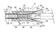
- FIG. 1is a side view of an exemplary system of the present invention for loading a tubular medical device into an introducer via a compressor and a split sleeve device.
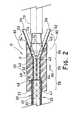
- FIG. 2is a cross-sectional view of an exemplary system of the present invention, including a tubular medical device, an introducer, a compressor, a portion of a split sleeve device, and an inserter.
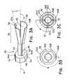
- FIG. 3Ais a perspective view of a split sleeve device.
- FIG. 3Bis an end view of the split sleeve device of FIG. 3A .
- FIG. 3Cis a view similar to FIG. 3B illustrating four sleeves.
- FIG. 4Ais a side view of an exemplary system of the present invention illustrating the loading of a tubular medical device into a compressor and a split sleeve device.
- FIG. 4Bis a side view of the system of FIG. 4A illustrating the loading of the tubular medical device into an introducer via the compressor and the split sleeve device.
- FIG. 1shows a system 10 for loading a tubular medical device 12 into an introducer 20 via a compressor 30 and a split sleeve device 50 .
- the tubular medical device 12such as a vascular stent or endprosthetic valve, preferably includes an abluminal surface and a luminal surface defining a cylindrical lumen about a longitudinal axis 14 extending longitudinally through the tubular medical device 12 from a first end 16 to a second end 18 .
- the tubular medical device 12may comprise a plurality of apertures or open spaces between metallic filaments (including fibers and wires), segments or regions.
- Typical structuresinclude: an open-mesh network comprising one or more knitted, woven or braided metallic filaments; an interconnected network of articulable segments; a coiled or helical structure comprising one or more metallic filaments; and, a patterned tubular metallic sheet (e.g., a laser cut tube).
- tubular medical device 12include endovascular, biliary, tracheal, gastrointestinal, urethral, ureteral, esophageal and coronary vascular stents or valves.
- the tubular medical devices 12may be, for example, balloon-expandable or self-expandable.
- the tubular medical device 12may include a plurality of interconnected struts and bends in a plurality of longitudinally connected sinusoidal hoop members.
- the tubular medical device 12may be radially movable between a compressed configuration ( FIG. 4B ) having a diameter, D, and a radially expanded, or un-compressed configuration, ( FIG. 1 ) having a diameter, D′.
- the tubular medical device 12can be reduced in diameter and introduced into the end of the introducer 20 by means of the compressor 30 .
- the tubular medical device 12may have a valve that can be formed by attaching a means for regulating fluid flow, such as a valve leaflet, to any support member of the tubular medical device 12 described according to any of the embodiments.
- a means for regulating fluid flowsuch as a valve leaflet
- One or more valve devicescan be implanted within the body vessel of a patient, especially a human, including for example in veins or arteries, to regulate fluid flow therein.
- the valve leafletcan be a single-leaflet type valve or a multiple-leaflet type valve.
- each valve leaflethas a first edge and a second edge.
- the first edgecan be disposed or attached on the middle region of the support member, while the second edge can extend between the first end and the second end of the support member and can be movable across the fluid flow path. Since the second edge can be moveable, the second edge can have an open position and a closed, or substantially closed, position to regulate fluid flow through fluid flow path of the tubular medical device 12
- valve leafletis a flexible structure configured to moveably traverse the fluid flow path of the support frame, and configured to sealably engage the opposite wall of the body vessel
- the valve leafletmay be securably mounted to the support member by any suitable means, including but not limited to, adhesive, fasteners, and tissue welding using heat and/or pressure.
- valve leafletmay be formed on the support member by any appropriate means, including but not limited to vapor deposition, spraying, electrostatic deposition, ultrasonic deposition, or dipping.
- a sheet of materialis cut to form a valve leaflet and the first edge of the leaflet is wrapped around portions of a support member and portions of the valve leaflet sealably connected together to fasten the valve leaflet around the support member.
- the valve leaflet(s)can be formed of a remodelable material, such as small intestine submucosa (SIS) or other extracellular matrix (ECM) material. Remodelable materials, such as extracellular matrix (ECM) materials, can be used to provide a non-thrombogenic surface in an implantable prosthetic valve.
- the valve leafletscan be formed from a remodelable material such that, upon implantation, the remodelable material can become vascularized to form a permanently non-thrombogenic leaflet surface.
- Small intestinal submucosa (SIS)is a commercially available ECM material (Cook Biotech Inc., West Lafayette, Ind.) derived from a porcine source and processed to retain remodelability.
- the remodelable materialcan be isolated from biological tissue by a variety of methods.
- a remodelable materialsuch as ECM material can be obtained from a segment of intestine that is first subjected to abrasion using a longitudinal wiping motion to remove both the outer layers (particularly the tunica serosa and the tunica muscularis) and the inner layers (the luminal portions of the tunica mucosa).
- the SISis rinsed with saline and optionally stored in a hydrated or dehydrated state until attached to the valve frame or implanted into the body.
- the tubular medical device 12may also include a separate anchor member attached to at least one of the first and second ends 16 , 18 , or therebetween, of the tubular medical device 12 , or may be an integral anchor member formed from at least one of the first and second ends 16 , 18 .
- anchor memberis used to denote any structure which can be used to help maintain the tubular medical device 12 in a desired relationship with a wall of the body vessel.
- a hook or barbcould be formed from, or attached to, at least one of the first and second ends 16 , 18 to serve as an anchor member.
- the anchor membermay be at least partially insertible into the wall of the body vessel for a mechanical engagement therewith.
- the tubular medical device 12may further include a graft or layer of biocompatible material covering at least a portion of the tubular medical device 12 .
- the graft materialmay be synthetic, such as polyester (e.g., Dacron®) (Invista, Wichita, Kans.), woven velour, polyurethane, PTFE, ePTFE, Gore-Tex® (W.L. Gore & Associates, Flagstaff, Ariz.), or heparin-coated fabric.
- the graft materialmay be a biological material such as bovine, equine, and/or porcine pericardium, peritoneal tissue, pleura, submucosal tissue, dura mater, an allograft, a homograft, a patient graft, or a cell-seeded tissue.
- a biological materialsuch as bovine, equine, and/or porcine pericardium, peritoneal tissue, pleura, submucosal tissue, dura mater, an allograft, a homograft, a patient graft, or a cell-seeded tissue.
- a portion of the tubular medical device 12may also be configured to include one or more mechanisms for the delivery of a therapeutic agent.
- the agentwill be in the form of a coating or other layer (or layers) of material placed on a surface region of the tubular medical device 12 or the graft, which is adapted to be released at the treatment site of implantation, or areas adjacent thereto, of the tubular medical device 12 .
- the introducer 20can be used for implanting the tubular medical device 12 into the body vessel.
- the introducer 20can receive the tubular medical device 12 by means of the compressor 30 .
- the introducer 20can include an outer catheter 22 , an inner catheter, and an inner shaft, all coaxially arranged.
- At the distal end of the inner shaftcan be arranged a catheter tip, each forming a structural unit that can be inserted or retracted axially into or out of the inner catheter.
- the axially oriented lumen for the tubular medical device 12 to be insertedis provided in the lumen 24 of the outer catheter 22 between the cylindrical inner wall of the outer catheter 22 and the cylindrical outer wall of the free section of the inner shaft.
- the cross-sectional area of the lumen 24 of the outer catheter 22is sized to accommodate a compressed tubular medical device 12 .
- the tubular medical device 12is positioned with one end at the distal end face of the inner catheter and with the other end at the proximal rear face of the catheter tip.
- the catheter tipmay be provided with an axial bore opening into the recess of the catheter tip or into the lumen of the inner shaft.
- the introducer 20may in addition be provided with a guide wire passing axially through the inner shaft and the catheter tip.
- the components of the introducer 20are axially dimensioned such that in the assembled state a space corresponding approximately to the length of the compressed tubular medical device 12 is provided between the proximal end face of the catheter tip and the distal end face of the inner catheter.
- the outer catheter 22is retracted relative to the catheter tip, and as a result the tubular medical device 12 radially expands under the action of its own elastic restoring force to the predetermined outer diameter and is released. Once the tubular medical device 12 has been released, the introducer 20 can be removed from the body vessel. It is noted that the described introducer is merely one non-limiting embodiment of an introducer, and other types of introducers known in the art are to be included within the scope of the invention.
- the compressor 30includes a hollow housing having a passage 32 connecting a stent delivery end 33 and a stent receiving end 34 .
- the passage 32can have a funnel portion 36 , an introducer opening 38 , and a transitioning portion 39 positioned between the funnel portion 36 and the introducer opening 28 .
- the funnel portion 36is shaped to radially compress the tubular medical device 12 before loading into the lumen 24 of the outer catheter 22 of the introducer 20 .
- the funnel portion 36is proximate the stent receiving end 34 and the introducer opening 38 is proximate the stent delivery end 33 .
- the funnel portion 36has a first end 40 with an opening having a cross-sectional area that is sized to receive the tubular medical device 12 in the expanded configuration.
- the surface of passage 32conically tapers in the direction of the introducer at an angle A to a second end 42 with a cross-sectional area less than the first end cross-sectional area, as shown in FIG. 2 .
- the angle Acan be approximately 5° to about 35° and preferably about 10°.
- the transitioning portion 39can be approximately equal to the length of the compressed tubular medical device 12 , but can be shorter or longer.
- the transitioning portionis preferably a cylindrical chamber having a first end 43 adjacent the second end 42 of the funnel portion 36 and a second end 44 adjacent to the introducer opening 38 .
- the first end 43can have a cross-sectional area substantially the same as the cross-sectional area of the second end 44 .
- the cross-sectional of the transitioning portion 39can be slightly smaller than the cross-sectional area of the lumen 24 of the outer catheter 22 to ensure an easier transition from the funnel portion 36 to inside the lumen 24 of the outer catheter 22 of the introducer 20 .
- the introducer opening 38shaped and sized to receive the outer catheter 22 of the introducer 20 and sleeves 52 of the split sleeve device 50 .
- the introducer opening 38is preferably a cylindrical chamber having a first end 46 that is adjacent to the second end 44 of the transitioning portion 39 and a second end 47 proximate the stent delivering end 33 .
- the cross-sectional area of the introducer opening 38is generally larger than the cross-sectional area of the transitioning portion 39 or the second end 42 of the funnel portion 36 . Because of the larger cross-sectional area, a seat 48 may be created at the juncture of the transitioning portion 39 and the introducer opening 38 .
- the surface of the seat 48can be generally perpendicular to the passage 32 or can be tapered, and can provide a stopping point for the introducer 20 when inserted into the introducer opening 38 .
- the split sleeve device 50is provided to urge the tubular medical device 12 to a compressed configuration.
- the split sleeve device 50includes at least one flexible sleeve 52 having a body 53 with a first end 54 and a second end 56 .
- the split sleeve device 50has two sleeves 52 a , 52 b ( FIG. 3B ) or four sleeves 52 a - d ( FIG. 3C ), but can be any number suitable to compress the tubular medical device 12 .
- a discrete layer 57 of sleevescan be formed by two or more sleeves 52 .
- the discrete layer 57 of sleevescan be overlapped by another discrete layer 59 of two or more sleeves 52 , as shown in FIG.
- each sleeve 52should be such that there can be overlap with adjacent sleeve edges of another discrete layer. It is preferable, however, that there be no collusion of sleeve edges of a given discrete layer.
- the split sleeve device 50can have (n) number of sleeves 52 and can have an angle B of 2 /n between the center of the body 53 of each sleeve 52 .
- the split sleeve devicemay also have (n′) number of pair of sleeves 52 and can have an angle of /n between the center of the body of each sleeve 52 of each pair.
- the body 53 of the one or more sleeves 52can be arcuate about the longitudinal axis 14 to form at least a portion of a tubular body.
- Each sleeve 52is preferably made of clear, flexible polymer that will not stretch or deform plastically.
- each sleeve 52can be made of Kapton®, Nylon blends, polyethylene, Polyethylene terephthalate (PET) or reinforced materials or other materials having similar properties desirable for the functionality of the sleeve 52 .
- PETPolyethylene terephthalate
- One non-limiting method to make each sleeve 52is to split or cut a thin-walled tubing into half, lengthwise to create strips.
- the tubingmay have a wall thickness of 0.13 mm (0.005′′) and a diameter or cross-sectional area less than the inside cross-sectional area of the outer catheter 22 of the introducer 20 .
- a portion 55 of the sleeve 52can also flare radially outward at an angle C, as shown in FIG. 3A . It is preferable that the angle C be substantially the same as angle A of the funnel portion 36 . For example, the angle C can be approximately 5° to about 35° and preferably about 10°.
- the portion 55 of each sleeve 52can be flared out at the angle C that is greater than the angle A.
- the split sleeve device 50includes a mounting device 58 that defines a hole 62 about the longitudinal axis 14 .
- the hole 62 of the mounting device 58is for receiving the sleeves 52 therethrough and is sized to receive the outer catheter 22 of the introducer 20 .
- the sleeves 52can be molded or formed integrally to the body of the mounting device 58 , bonded by adhesives, soldered, welded or otherwise mechanically attached.
- the mounting device 58can be ring-like structure or a cylindrical body having a number (k) of planar surfaces 64 machined on the body of the mounting device 58 .
- the mounting device 58can be polygon shaped with (k) number of planar surfaces 64 and can have an angle B of 2 /k between the center of the body of each planar surface 64 .
- the number (k) of planar surface 64is preferably proportional to the number of sleeves 52 .
- the mounting devicecan have two planar surfaces 64 a , 64 b ( FIG. 3B ) or four planar surfaces 64 a - d ( FIG. 3C )
- the first end 54 of the sleeves 52can be coupled to the mounting device 58 , and can conform to the hole 62 of the mounting device 58 , extending outward from the hole 62 for wrapping around the mounting device 58 to attach the planar surface 64 .
- the second end 56can be flared radially outward at the angle C to receive the tubular medical device 12 therein.
- each sleeve 52can be separated by a longitudinal gap 66 or split with respect to the adjacent sleeve of the same discrete layer that allows radial flexibility to a degree that when radially collapsing compresses the tubular medical device 12 .
- the sleeves 52 of one discrete layer 57can overlap the sleeves of another discrete layer 59 , where each discrete layer coves the longitudinal gap of the other discrete layer.
- the sleeves 52can be inserted into each of the passage 32 of the compressor 30 and the mounting device 58 , and translated axially along the longitudinal axis 14 to adjacent the stent delivery end 33 . While in the passage 32 , the sleeves 52 function as a liner, separating the passage walls of the compressor 30 from the tubular medical device 12 .
- Some examplesinclude sleeves 52 having a length greater than the length of the passage 32 to extend beyond the stent receiving end 34 .
- the length of the sleeve 52is suitable that, when collapsing the tubular medical device 12 , the second end 56 of the sleeve 52 extends past the first end 16 of the tubular medical device 12 .
- the body 53 of the sleeve in such examplescan be flexible in order for the second end 56 of the sleeve 52 to extend outward from the passage 32 of the compressor 30 for wrapping around the exterior surfaces of the compressor 30 , as shown in FIGS. 1 and 2 .
- an inserter 70that can be provided to retain the tubular medical device 12 about the longitudinal axis 14 while the tubular medical device 12 collapses to the compressed configuration during loading.
- the inserter 70can have a collapsible member 72 configured to retain the tubular medical device 12 .
- One example of the collapsible member 72includes a plurality of arms 74 extending radially outward from the inserter 70 . Each arm 74 can have a stent engaging end 76 for contacting and retaining the tubular medical device 12 about the longitudinal axis 14 while the tubular medical device 12 is urged into the stent receiving end 34 .
- the collapsible member 72Upon further travel into the funnel portion 36 , the collapsible member 72 can be collapsible to a cross sectional area less than the cross sectional area of the outer catheter 22 of the introducer 20 . This can allow the collapsible member 72 to be inserted into the lumen 24 of the outer catheter 24 of the introducer 20 when urging the tubular medical device 12 therein.
- a method of loading the tubular medical device 12 into the introducer 20is provided One step is to insert each sleeve 52 of the split sleeve device 50 through the passage 32 of the compressor 30 . Because the portion 55 of the sleeve 52 is biased to radially expand, the portion 55 of the sleeve 52 will expand to contact the surface of the funnel portion 36 . The second end 56 of each sleeve 52 may be wrapped around the stent receiving end 34 and the exterior surface of the compressor 30 . The mounting device 58 of the split sleeve device 50 can be positioned adjacent to the stent delivery end 33 of the compressor 30 .
- the introducer 20can be inserted through the hole 62 of the mounting device 58 and into the introducer opening 38 through the stent delivery end 33 of the compressor 30 .
- the tubular medical device 12can be inserted into the funnel portion 36 through the stent receiving end 34 of the compressor 30 , where the second end 18 of the tubular medical device 12 contacts the wall of the funnel portion 36 and is positioned along the longitudinal axis 14 ( FIG. 1 ).
- the compressor 30can be translated along the longitudinal axis 14 relative to the mounting device 58 ( FIG. 4A ).
- the mounting device 58 and/or inserter 70is fixed relative to the compressor 30 that is translated away in a direction, represented by arrow 80 , away from the mounting device 58 .
- the introducer 20slidably engages the hole 62 of the mounting device 58 to remain contacting the introducer opening 38 , preferably the seat 48 , in order to be in a position to receive the tubular medical device 12 .
- the compressorcan be fixed, and the mounting device 58 and/or inserter 70 can be translated away in a direction away from the compressor.
- the hole of the mounting deviceslidably engages the outside wall of the introducer, while the introducer remains contacting the introducer opening, preferably the seat, in order to be in a position to receive the tubular medical device. It may also be desirable for both the mounting device and the compressor to each move away from one another.
- This translation of the compressor 30 relative to the mounting device 58can urge the sleeves 52 to collapse, radially compressing the tubular medical device 12 into the compressed configuration.
- the cross-sectional area of the tubular medical device 12 in the compressed configurationcan be substantially similar to the cross-sectional area of the second end 42 of the funnel portion 33 .
- the second end 56 of the sleevesWhen the second end 56 of the sleeves is wrapped around the stent receiving end 34 and the exterior surface of the compressor 30 as illustrated in FIG. 2 , the second end 56 will rotate in a direction, represented by arrow 82 , radially inward.
- the tubular medical device 12may then be urged into the transitioning portion 39 of the compressor 30 , which may have a different cross-sectional area than that of the introducer opening 38 .
- the tubular medical device 12can then be loaded into the lumen 24 of the outer catheter 22 of the introducer 20 ( FIG. 4B ).
- the inserter 70can be used to facilitate the process of loading the tubular medical device 12 into the introducer 20 .
- the tubular medical device 12can be inserted into the funnel portion 36 through the stent receiving end 34 of the compressor 30 .
- the inserter 70can engage and retain the tubular medical device 12 while the compressor 30 is translated along the longitudinal axis 14 relative to the mounting device 58 .
- the inserter 70may assist in urging the tubular medical device 12 into the transitioning portion 39 of the compressor 30 .
- the inserter 70can load the tubular medical device 12 into the lumen 24 of the outer catheter 22 of the introducer 20 .
- the loaded introducer 20may then be withdrawn from the compressor 30 and the split sleeve device 50 , and then introduced to the body vessel to deploy the tubular medical device 12 to a treatment site.
- the compressor 30 and/or the split sleeve device 50may be individually packaged and sterilized. Accordingly, the interventionalist can load the tubular medical device 12 at the bedside of a patient, which can be important when the tubular medical device 12 needs to be pre-treated, such as hydrated, or remain un-compressed up until the time of the procedure. Further, the compressor 30 and/or the split sleeve device 50 are preferably disposable after one-time use, or alternatively can be made of materials that can be cleaned, reset, sterilized and reused.
Landscapes
- Health & Medical Sciences (AREA)
- Engineering & Computer Science (AREA)
- Biomedical Technology (AREA)
- Cardiology (AREA)
- Oral & Maxillofacial Surgery (AREA)
- Transplantation (AREA)
- Heart & Thoracic Surgery (AREA)
- Vascular Medicine (AREA)
- Life Sciences & Earth Sciences (AREA)
- Animal Behavior & Ethology (AREA)
- General Health & Medical Sciences (AREA)
- Public Health (AREA)
- Veterinary Medicine (AREA)
- Media Introduction/Drainage Providing Device (AREA)
Abstract
Description

Claims (20)
Priority Applications (1)
| Application Number | Priority Date | Filing Date | Title |
|---|---|---|---|
| US12/204,376US8359721B2 (en) | 2008-09-04 | 2008-09-04 | Sliding split-sleeve implant compressor |
Applications Claiming Priority (1)
| Application Number | Priority Date | Filing Date | Title |
|---|---|---|---|
| US12/204,376US8359721B2 (en) | 2008-09-04 | 2008-09-04 | Sliding split-sleeve implant compressor |
Publications (2)
| Publication Number | Publication Date |
|---|---|
| US20100057185A1 US20100057185A1 (en) | 2010-03-04 |
| US8359721B2true US8359721B2 (en) | 2013-01-29 |
Family
ID=41726528
Family Applications (1)
| Application Number | Title | Priority Date | Filing Date |
|---|---|---|---|
| US12/204,376Active2031-11-28US8359721B2 (en) | 2008-09-04 | 2008-09-04 | Sliding split-sleeve implant compressor |
Country Status (1)
| Country | Link |
|---|---|
| US (1) | US8359721B2 (en) |
Cited By (13)
| Publication number | Priority date | Publication date | Assignee | Title |
|---|---|---|---|---|
| US20100049297A1 (en)* | 2008-08-21 | 2010-02-25 | C.R. Bard, Inc. | Method of loading a stent into a sheath |
| US20110046712A1 (en)* | 2009-08-20 | 2011-02-24 | Cook Incorporated | Loading apparatus and system for expandable intraluminal medical devices |
| US20110060397A1 (en)* | 2008-05-09 | 2011-03-10 | C.R. Bard, Inc. | Method of loading a stent into a sheath |
| US20110184509A1 (en)* | 2010-01-27 | 2011-07-28 | Abbott Laboratories | Dual sheath assembly and method of use |
| US20110208292A1 (en)* | 2010-02-19 | 2011-08-25 | Abbott Laboratories | Hinged sheath assembly and method of use |
| US20110208296A1 (en)* | 2010-02-24 | 2011-08-25 | Medtronic Ventor Technologies Ltd. | Catheter Assembly with Valve Crimping Accessories |
| US20140058438A1 (en)* | 2012-08-21 | 2014-02-27 | St. Jude Medical Puerto Rico Llc | Carrier tubes for closure devices |
| US20150250587A1 (en)* | 2012-10-09 | 2015-09-10 | Biotronik Ag | Crimping tool for a prosthetic device and method for crimping a prosthetic device with a crimping tool |
| US10449335B2 (en) | 2013-05-03 | 2019-10-22 | C.R. Bard, Inc. | Peelable protective sheath |
| US11376110B2 (en) | 2018-07-06 | 2022-07-05 | Muffin Incorporated | Storage devices, loading devices, delivery systems, kits, and associated methods |
| US11389627B1 (en) | 2018-10-02 | 2022-07-19 | Lutonix Inc. | Balloon protectors, balloon-catheter assemblies, and methods thereof |
| US11471311B2 (en) | 2018-04-09 | 2022-10-18 | Boston Scientific Scimed, Inc. | Stent delivery system with reduced deployment force |
| US12343271B2 (en) | 2021-05-03 | 2025-07-01 | Medtronic, Inc. | Loading tools for prosthetic valve devices |
Families Citing this family (78)
| Publication number | Priority date | Publication date | Assignee | Title |
|---|---|---|---|---|
| US6254564B1 (en) | 1998-09-10 | 2001-07-03 | Percardia, Inc. | Left ventricular conduit with blood vessel graft |
| US10307147B2 (en) | 1999-08-09 | 2019-06-04 | Edwards Lifesciences Corporation | System for improving cardiac function by sealing a partitioning membrane within a ventricle |
| US8388672B2 (en) | 1999-08-09 | 2013-03-05 | Cardiokinetix, Inc. | System for improving cardiac function by sealing a partitioning membrane within a ventricle |
| US9694121B2 (en) | 1999-08-09 | 2017-07-04 | Cardiokinetix, Inc. | Systems and methods for improving cardiac function |
| US10064696B2 (en) | 2000-08-09 | 2018-09-04 | Edwards Lifesciences Corporation | Devices and methods for delivering an endocardial device |
| US9332992B2 (en) | 2004-08-05 | 2016-05-10 | Cardiokinetix, Inc. | Method for making a laminar ventricular partitioning device |
| US9332993B2 (en) | 2004-08-05 | 2016-05-10 | Cardiokinetix, Inc. | Devices and methods for delivering an endocardial device |
| US6866679B2 (en) | 2002-03-12 | 2005-03-15 | Ev3 Inc. | Everting stent and stent delivery system |
| DE102005003632A1 (en) | 2005-01-20 | 2006-08-17 | Fraunhofer-Gesellschaft zur Förderung der angewandten Forschung e.V. | Catheter for the transvascular implantation of heart valve prostheses |
| US7896915B2 (en) | 2007-04-13 | 2011-03-01 | Jenavalve Technology, Inc. | Medical device for treating a heart valve insufficiency |
| US9044318B2 (en) | 2008-02-26 | 2015-06-02 | Jenavalve Technology Gmbh | Stent for the positioning and anchoring of a valvular prosthesis |
| BR112012021347A2 (en) | 2008-02-26 | 2019-09-24 | Jenavalve Tecnology Inc | stent for positioning and anchoring a valve prosthesis at an implantation site in a patient's heart |
| EP2520320B1 (en)* | 2008-07-01 | 2016-11-02 | Endologix, Inc. | Catheter system |
| US20100292779A1 (en)* | 2009-05-15 | 2010-11-18 | Helmut Straubinger | Device for compressing a stent and a system as well as a method for loading a stent into a medical delivery system |
| US8790242B2 (en) | 2009-10-26 | 2014-07-29 | Cardiokinetix, Inc. | Ventricular volume reduction |
| US10856978B2 (en) | 2010-05-20 | 2020-12-08 | Jenavalve Technology, Inc. | Catheter system |
| WO2011147849A1 (en) | 2010-05-25 | 2011-12-01 | Jenavalve Technology Inc. | Prosthetic heart valve and transcatheter delivered endoprosthesis comprising a prosthetic heart valve and a stent |
| US9387077B2 (en)* | 2010-05-27 | 2016-07-12 | Medtronic Vascular Galway | Catheter assembly with prosthesis crimping and prosthesis retaining accessories |
| EP2605729A2 (en)* | 2010-08-17 | 2013-06-26 | St. Jude Medical, Cardiology Division, Inc. | A device for collapsing and loading a heart valve into a minimally invasive delivery system |
| US9155619B2 (en) | 2011-02-25 | 2015-10-13 | Edwards Lifesciences Corporation | Prosthetic heart valve delivery apparatus |
| US8808350B2 (en) | 2011-03-01 | 2014-08-19 | Endologix, Inc. | Catheter system and methods of using same |
| US8734500B2 (en)* | 2011-09-27 | 2014-05-27 | DePuy Synthes Products, LLC | Distal detachment mechanisms for vascular devices |
| US9347900B2 (en) | 2011-10-14 | 2016-05-24 | Pacific Biosciences Of California, Inc. | Real-time redox sequencing |
| US9192496B2 (en)* | 2011-10-31 | 2015-11-24 | Merit Medical Systems, Inc. | Systems and methods for sheathing an implantable device |
| EP3222627B1 (en) | 2012-02-15 | 2019-08-07 | Pacific Biosciences of California, Inc. | Polymerase enzyme substrates with protein shield |
| US20130226278A1 (en) | 2012-02-23 | 2013-08-29 | Tyco Healthcare Group Lp | Methods and apparatus for luminal stenting |
| US9072624B2 (en) | 2012-02-23 | 2015-07-07 | Covidien Lp | Luminal stenting |
| US9078659B2 (en) | 2012-04-23 | 2015-07-14 | Covidien Lp | Delivery system with hooks for resheathability |
| US9724222B2 (en)* | 2012-07-20 | 2017-08-08 | Covidien Lp | Resheathable stent delivery system |
| US10130500B2 (en) | 2013-07-25 | 2018-11-20 | Covidien Lp | Methods and apparatus for luminal stenting |
| US10045867B2 (en) | 2013-08-27 | 2018-08-14 | Covidien Lp | Delivery of medical devices |
| US9782186B2 (en) | 2013-08-27 | 2017-10-10 | Covidien Lp | Vascular intervention system |
| CN105491978A (en) | 2013-08-30 | 2016-04-13 | 耶拿阀门科技股份有限公司 | Radially collapsible frame for a prosthetic valve and method for manufacturing such a frame |
| EP4000560B1 (en)* | 2013-09-16 | 2024-08-21 | Boston Scientific Medical Device Limited | A loading tube apparatus for compressing/loading stent-valves |
| KR20170066470A (en) | 2014-09-28 | 2017-06-14 | 카디오키네틱스 인크. | Apparatuses for treating cardiac dysfunction |
| US10302972B2 (en) | 2015-01-23 | 2019-05-28 | Pacific Biosciences Of California, Inc. | Waveguide transmission |
| WO2016141295A1 (en) | 2015-03-05 | 2016-09-09 | Merit Medical Systems, Inc. | Vascular prosthesis deployment device and method of use |
| EP3270826B1 (en)* | 2015-03-20 | 2020-01-01 | St. Jude Medical, Cardiology Division, Inc. | Mitral valve loading tool |
| EP3270825B1 (en) | 2015-03-20 | 2020-04-22 | JenaValve Technology, Inc. | Heart valve prosthesis delivery system |
| US10709555B2 (en) | 2015-05-01 | 2020-07-14 | Jenavalve Technology, Inc. | Device and method with reduced pacemaker rate in heart valve replacement |
| EP3313330A4 (en)* | 2015-06-29 | 2019-03-20 | 480 Biomedical, Inc. | SUPPORT LOADING AND DISTRIBUTION SYSTEMS |
| WO2017004265A1 (en) | 2015-06-30 | 2017-01-05 | Endologix, Inc. | Locking assembly for coupling guidewire to delivery system |
| US10470906B2 (en) | 2015-09-15 | 2019-11-12 | Merit Medical Systems, Inc. | Implantable device delivery system |
| WO2017195125A1 (en) | 2016-05-13 | 2017-11-16 | Jenavalve Technology, Inc. | Heart valve prosthesis delivery system and method for delivery of heart valve prosthesis with introducer sheath and loading system |
| EP3454788B1 (en) | 2016-05-13 | 2020-02-05 | St. Jude Medical, Cardiology Division, Inc. | Mitral valve delivery device |
| CN115054413A (en) | 2016-09-29 | 2022-09-16 | 美国医疗设备有限公司 | Method of adjusting effective length of stent and prosthesis delivery catheter assembly |
| US10376396B2 (en) | 2017-01-19 | 2019-08-13 | Covidien Lp | Coupling units for medical device delivery systems |
| WO2018138658A1 (en) | 2017-01-27 | 2018-08-02 | Jenavalve Technology, Inc. | Heart valve mimicry |
| EP4467111A3 (en) | 2017-03-15 | 2025-03-05 | Merit Medical Systems, Inc. | Transluminal stents |
| US11628078B2 (en) | 2017-03-15 | 2023-04-18 | Merit Medical Systems, Inc. | Transluminal delivery devices and related kits and methods |
| USD836194S1 (en) | 2017-03-21 | 2018-12-18 | Merit Medical Systems, Inc. | Stent deployment device |
| US10898330B2 (en) | 2017-03-28 | 2021-01-26 | Edwards Lifesciences Corporation | Positioning, deploying, and retrieving implantable devices |
| US11357484B2 (en)* | 2017-03-30 | 2022-06-14 | Medtronic, Inc. | Medical device retrieval with multiple snares |
| US20180289521A1 (en)* | 2017-04-11 | 2018-10-11 | Cook Medical Technologies Llc | Stent delivery system |
| EP3446731A1 (en)* | 2017-08-23 | 2019-02-27 | ECP Entwicklungsgesellschaft mbH | Device for compressing a compressible part of a catheter pump |
| US10856982B2 (en) | 2017-09-19 | 2020-12-08 | St. Jude Medical, Cardiology Division, Inc. | Transapical mitral valve delivery system |
| CN107714245B (en)* | 2017-11-16 | 2023-08-25 | 四川大学华西医院 | Anti-reflux bracket conveying system |
| CN107874881B (en)* | 2017-12-27 | 2024-08-02 | 江苏启灏医疗科技有限公司 | Uterine cavity support conveying assembly |
| US11096812B2 (en)* | 2018-01-22 | 2021-08-24 | St. Jude Medical, Cardiology Division, Inc. | Delivery system and method for loading a self-expanding collapsible heart valve |
| US11413176B2 (en) | 2018-04-12 | 2022-08-16 | Covidien Lp | Medical device delivery |
| US11123209B2 (en) | 2018-04-12 | 2021-09-21 | Covidien Lp | Medical device delivery |
| US10786377B2 (en) | 2018-04-12 | 2020-09-29 | Covidien Lp | Medical device delivery |
| US11071637B2 (en) | 2018-04-12 | 2021-07-27 | Covidien Lp | Medical device delivery |
| US11737656B2 (en) | 2018-06-01 | 2023-08-29 | PatCom Medical Inc. | Catheter and tube introducer |
| US11413174B2 (en) | 2019-06-26 | 2022-08-16 | Covidien Lp | Core assembly for medical device delivery systems |
| US11974917B2 (en) | 2019-12-20 | 2024-05-07 | Medtronic Vascular, Inc. | Hydraulic crimping device |
| US11504254B2 (en)* | 2020-03-05 | 2022-11-22 | Fluid Biomed Inc. | System and methods for compressing endovascular devices |
| CN111618792B (en)* | 2020-05-20 | 2024-06-04 | 大连泰凯工业有限公司 | Immersed type quick clamping and stretching nut mechanism and use method thereof |
| EP4185239A4 (en) | 2020-07-24 | 2024-08-07 | Merit Medical Systems, Inc. | ESOPHAGEAL STENT PROSTHESES AND RELATED METHODS |
| US12370045B2 (en)* | 2020-09-18 | 2025-07-29 | Medtronic, Inc. | Methods and systems for delivery device insertion during medical device crimp processes |
| CA3194910A1 (en) | 2020-10-26 | 2022-05-05 | Tiffany ETHRIDGE | Esophageal stents with helical thread |
| US12042413B2 (en) | 2021-04-07 | 2024-07-23 | Covidien Lp | Delivery of medical devices |
| JP7730980B2 (en)* | 2021-07-13 | 2025-08-28 | ボストン サイエンティフィック サイムド,インコーポレイテッド | Apparatus for compressing a replacement heart valve implant - Patent Application 20070122997 |
| US12109137B2 (en) | 2021-07-30 | 2024-10-08 | Covidien Lp | Medical device delivery |
| US11944558B2 (en) | 2021-08-05 | 2024-04-02 | Covidien Lp | Medical device delivery devices, systems, and methods |
| WO2023233349A1 (en)* | 2022-06-03 | 2023-12-07 | Medtronic, Inc. | Funnel crimper with tissue compressor |
| WO2024102411A1 (en) | 2022-11-09 | 2024-05-16 | Jenavalve Technology, Inc. | Catheter system for sequential deployment of an expandable implant |
| WO2024132115A1 (en)* | 2022-12-20 | 2024-06-27 | T-Heart SAS | Loading system for a stent device |
Citations (38)
| Publication number | Priority date | Publication date | Assignee | Title |
|---|---|---|---|---|
| US5026377A (en)* | 1989-07-13 | 1991-06-25 | American Medical Systems, Inc. | Stent placement instrument and method |
| EP0607468A1 (en)* | 1992-12-16 | 1994-07-27 | Schneider (Europe) Ag | Stent placement instrument |
| US5630830A (en) | 1996-04-10 | 1997-05-20 | Medtronic, Inc. | Device and method for mounting stents on delivery systems |
| US5672169A (en)* | 1996-04-10 | 1997-09-30 | Medtronic, Inc. | Stent mounting device |
| US5709703A (en) | 1995-11-14 | 1998-01-20 | Schneider (Europe) A.G. | Stent delivery device and method for manufacturing same |
| US5746764A (en) | 1995-12-04 | 1998-05-05 | Atrion Medical Products, Inc. | Stent compression instrument |
| US5783227A (en)* | 1996-01-22 | 1998-07-21 | Cordis Corporation | Catheter balloon folding device |
| US6004328A (en) | 1997-06-19 | 1999-12-21 | Solar; Ronald J. | Radially expandable intraluminal stent and delivery catheter therefore and method of using the same |
| US6068635A (en)* | 1998-03-04 | 2000-05-30 | Schneider (Usa) Inc | Device for introducing an endoprosthesis into a catheter shaft |
| US6090035A (en)* | 1999-03-19 | 2000-07-18 | Isostent, Inc. | Stent loading assembly for a self-expanding stent |
| US6092273A (en)* | 1998-07-28 | 2000-07-25 | Advanced Cardiovascular Systems, Inc. | Method and apparatus for a stent crimping device |
| US6110198A (en) | 1995-10-03 | 2000-08-29 | Medtronic Inc. | Method for deploying cuff prostheses |
| US6126685A (en) | 1994-06-08 | 2000-10-03 | Medtronic, Inc. | Apparatus and methods for placement and repositioning of intraluminal prostheses |
| US6132458A (en) | 1998-05-15 | 2000-10-17 | American Medical Systems, Inc. | Method and device for loading a stent |
| US6149680A (en)* | 1998-06-04 | 2000-11-21 | Scimed Life Systems, Inc. | Stent loading tool |
| US6162244A (en) | 1996-03-29 | 2000-12-19 | Willy Ruesch Ag | Layered stent |
| US6167605B1 (en) | 1997-09-12 | 2001-01-02 | Advanced Cardiovascular Systems, Inc. | Collet type crimping tool |
| US6514280B1 (en)* | 1998-04-02 | 2003-02-04 | Salviac Limited | Delivery catheter |
| US20030083730A1 (en) | 2001-10-25 | 2003-05-01 | Scimed Life Systems, Inc. | Loading cartridge for self-expanding stent |
| US20030114910A1 (en)* | 2001-12-18 | 2003-06-19 | Juhani Laakso Kari Aarne | Stent delivery apparatus and method |
| US6618921B1 (en)* | 2000-11-16 | 2003-09-16 | Scimed Life Systems, Inc. | Bare stent ship and crimp device |
| US20040015224A1 (en)* | 2002-07-22 | 2004-01-22 | Armstrong Joseph R. | Endoluminal expansion system |
| US6926732B2 (en)* | 2001-06-01 | 2005-08-09 | Ams Research Corporation | Stent delivery device and method |
| US20060052750A1 (en)* | 2004-09-09 | 2006-03-09 | Jay Lenker | Expandable transluminal sheath |
| US7127789B2 (en)* | 2001-01-22 | 2006-10-31 | Scimed Life Systems, Inc. | Method of manufacturing a stent delivery system |
| US20070118207A1 (en)* | 2005-05-04 | 2007-05-24 | Aga Medical Corporation | System for controlled delivery of stents and grafts |
| US20070198077A1 (en)* | 2006-01-20 | 2007-08-23 | Cully Edward H | Device for rapid repair of body conduits |
| US20070270932A1 (en)* | 2006-05-19 | 2007-11-22 | Boston Scientific Scimed, Inc. | Apparatus and method for loading and delivering a stent |
| US20080119890A1 (en)* | 2002-06-14 | 2008-05-22 | Ev3 Inc. | Rapid exchange catheters usable with embolic protection devices |
| US20090076587A1 (en)* | 2007-09-13 | 2009-03-19 | Cully Edward H | Stented Vascular Graft |
| US20090248142A1 (en)* | 2008-03-25 | 2009-10-01 | Medtronic Vascular, Inc. | Methods, Devices and Systems for Treating Venous Insufficiency |
| US7691109B2 (en)* | 1999-01-22 | 2010-04-06 | Gore Enterprise Holdings, Inc. | Method of producing low profile stent and graft combination |
| US20110015714A1 (en)* | 2003-10-10 | 2011-01-20 | Atkinson Robert E | Lead stabilization devices and methods |
| US8006535B2 (en)* | 2007-07-12 | 2011-08-30 | Sorin Biomedica Cardio S.R.L. | Expandable prosthetic valve crimping device |
| US20110221113A1 (en)* | 2008-09-30 | 2011-09-15 | Christoph Diederichs | Apparatus and method for processing a stent |
| US20110258833A1 (en)* | 1999-09-22 | 2011-10-27 | Boston Scientific Scimed, Inc. | Method and apparatus for contracting, or crimping stents |
| US20110301703A1 (en)* | 2009-02-20 | 2011-12-08 | St. Jude Medical, Inc. | Devices and methods for collapsing prosthetic heart valves |
| US8112857B2 (en)* | 2009-01-20 | 2012-02-14 | Abbott Laboratories Vascular Enterprises Limited | Stent crimping device |
- 2008
- 2008-09-04USUS12/204,376patent/US8359721B2/enactiveActive
Patent Citations (47)
| Publication number | Priority date | Publication date | Assignee | Title |
|---|---|---|---|---|
| US5026377A (en)* | 1989-07-13 | 1991-06-25 | American Medical Systems, Inc. | Stent placement instrument and method |
| EP0607468A1 (en)* | 1992-12-16 | 1994-07-27 | Schneider (Europe) Ag | Stent placement instrument |
| US6126685A (en) | 1994-06-08 | 2000-10-03 | Medtronic, Inc. | Apparatus and methods for placement and repositioning of intraluminal prostheses |
| US6110198A (en) | 1995-10-03 | 2000-08-29 | Medtronic Inc. | Method for deploying cuff prostheses |
| US5709703A (en) | 1995-11-14 | 1998-01-20 | Schneider (Europe) A.G. | Stent delivery device and method for manufacturing same |
| US5746764A (en) | 1995-12-04 | 1998-05-05 | Atrion Medical Products, Inc. | Stent compression instrument |
| US5783227A (en)* | 1996-01-22 | 1998-07-21 | Cordis Corporation | Catheter balloon folding device |
| US6162244A (en) | 1996-03-29 | 2000-12-19 | Willy Ruesch Ag | Layered stent |
| US5672169A (en)* | 1996-04-10 | 1997-09-30 | Medtronic, Inc. | Stent mounting device |
| US5630830A (en) | 1996-04-10 | 1997-05-20 | Medtronic, Inc. | Device and method for mounting stents on delivery systems |
| US6004328A (en) | 1997-06-19 | 1999-12-21 | Solar; Ronald J. | Radially expandable intraluminal stent and delivery catheter therefore and method of using the same |
| US6167605B1 (en) | 1997-09-12 | 2001-01-02 | Advanced Cardiovascular Systems, Inc. | Collet type crimping tool |
| US6068635A (en)* | 1998-03-04 | 2000-05-30 | Schneider (Usa) Inc | Device for introducing an endoprosthesis into a catheter shaft |
| US20030236545A1 (en)* | 1998-04-02 | 2003-12-25 | Salviac Limited | Delivery catheter |
| US6514280B1 (en)* | 1998-04-02 | 2003-02-04 | Salviac Limited | Delivery catheter |
| US6132458A (en) | 1998-05-15 | 2000-10-17 | American Medical Systems, Inc. | Method and device for loading a stent |
| US6471718B1 (en) | 1998-05-15 | 2002-10-29 | American Medical Systems, Inc. | Method and device for loading a stent |
| US6149680A (en)* | 1998-06-04 | 2000-11-21 | Scimed Life Systems, Inc. | Stent loading tool |
| US6092273A (en)* | 1998-07-28 | 2000-07-25 | Advanced Cardiovascular Systems, Inc. | Method and apparatus for a stent crimping device |
| US7691109B2 (en)* | 1999-01-22 | 2010-04-06 | Gore Enterprise Holdings, Inc. | Method of producing low profile stent and graft combination |
| US6090035A (en)* | 1999-03-19 | 2000-07-18 | Isostent, Inc. | Stent loading assembly for a self-expanding stent |
| US20110258833A1 (en)* | 1999-09-22 | 2011-10-27 | Boston Scientific Scimed, Inc. | Method and apparatus for contracting, or crimping stents |
| US6618921B1 (en)* | 2000-11-16 | 2003-09-16 | Scimed Life Systems, Inc. | Bare stent ship and crimp device |
| US6920674B2 (en)* | 2000-11-16 | 2005-07-26 | Scimed Life Systems, Inc. | Bare stent ship and crimp device |
| US7127789B2 (en)* | 2001-01-22 | 2006-10-31 | Scimed Life Systems, Inc. | Method of manufacturing a stent delivery system |
| US6926732B2 (en)* | 2001-06-01 | 2005-08-09 | Ams Research Corporation | Stent delivery device and method |
| US20030083730A1 (en) | 2001-10-25 | 2003-05-01 | Scimed Life Systems, Inc. | Loading cartridge for self-expanding stent |
| US6902575B2 (en)* | 2001-12-18 | 2005-06-07 | Linvatec Biomaterials, Inc. | Stent delivery apparatus and method |
| US20030114910A1 (en)* | 2001-12-18 | 2003-06-19 | Juhani Laakso Kari Aarne | Stent delivery apparatus and method |
| US7717934B2 (en)* | 2002-06-14 | 2010-05-18 | Ev3 Inc. | Rapid exchange catheters usable with embolic protection devices |
| US20080119890A1 (en)* | 2002-06-14 | 2008-05-22 | Ev3 Inc. | Rapid exchange catheters usable with embolic protection devices |
| US20080188888A1 (en)* | 2002-06-14 | 2008-08-07 | Ev3 Inc. | Rapid exchange catheters usable with embolic protection devices |
| US20100179491A1 (en)* | 2002-06-14 | 2010-07-15 | Ev3 Inc. | Rapid exchange catheters usable with embolic protection devices |
| US20060190071A1 (en)* | 2002-07-22 | 2006-08-24 | Armstrong Joseph R | Endoluminal expansion system |
| US20040015224A1 (en)* | 2002-07-22 | 2004-01-22 | Armstrong Joseph R. | Endoluminal expansion system |
| US20100331956A1 (en)* | 2002-07-22 | 2010-12-30 | Armstrong Joseph R | Endoluminal expansion system |
| US20110015714A1 (en)* | 2003-10-10 | 2011-01-20 | Atkinson Robert E | Lead stabilization devices and methods |
| US20060052750A1 (en)* | 2004-09-09 | 2006-03-09 | Jay Lenker | Expandable transluminal sheath |
| US20070118207A1 (en)* | 2005-05-04 | 2007-05-24 | Aga Medical Corporation | System for controlled delivery of stents and grafts |
| US20070198077A1 (en)* | 2006-01-20 | 2007-08-23 | Cully Edward H | Device for rapid repair of body conduits |
| US20070270932A1 (en)* | 2006-05-19 | 2007-11-22 | Boston Scientific Scimed, Inc. | Apparatus and method for loading and delivering a stent |
| US8006535B2 (en)* | 2007-07-12 | 2011-08-30 | Sorin Biomedica Cardio S.R.L. | Expandable prosthetic valve crimping device |
| US20090076587A1 (en)* | 2007-09-13 | 2009-03-19 | Cully Edward H | Stented Vascular Graft |
| US20090248142A1 (en)* | 2008-03-25 | 2009-10-01 | Medtronic Vascular, Inc. | Methods, Devices and Systems for Treating Venous Insufficiency |
| US20110221113A1 (en)* | 2008-09-30 | 2011-09-15 | Christoph Diederichs | Apparatus and method for processing a stent |
| US8112857B2 (en)* | 2009-01-20 | 2012-02-14 | Abbott Laboratories Vascular Enterprises Limited | Stent crimping device |
| US20110301703A1 (en)* | 2009-02-20 | 2011-12-08 | St. Jude Medical, Inc. | Devices and methods for collapsing prosthetic heart valves |
Cited By (24)
| Publication number | Priority date | Publication date | Assignee | Title |
|---|---|---|---|---|
| US20110060397A1 (en)* | 2008-05-09 | 2011-03-10 | C.R. Bard, Inc. | Method of loading a stent into a sheath |
| US9687370B2 (en)* | 2008-05-09 | 2017-06-27 | C.R. Bard, Inc. | Method of loading a stent into a sheath |
| US20100049297A1 (en)* | 2008-08-21 | 2010-02-25 | C.R. Bard, Inc. | Method of loading a stent into a sheath |
| US9833349B2 (en)* | 2008-08-21 | 2017-12-05 | C. R. Bard, Inc. | Method of loading a stent into a sheath |
| US8585019B2 (en)* | 2009-08-20 | 2013-11-19 | Cook Medical Technologies Llc | Loading apparatus and system for expandable intraluminal medical devices |
| US20110046712A1 (en)* | 2009-08-20 | 2011-02-24 | Cook Incorporated | Loading apparatus and system for expandable intraluminal medical devices |
| US11974932B2 (en) | 2009-08-20 | 2024-05-07 | Cook Medical Technologies Llc | Loading apparatus and system for expandable intraluminal medical devices |
| US10596019B2 (en) | 2009-08-20 | 2020-03-24 | Cook Medical Technologies Llc | Loading apparatus and system for expandable intraluminal medical devices |
| US9216102B2 (en) | 2009-08-20 | 2015-12-22 | Cook Medical Technologies Llc | Loading apparatus and system for expandable intraluminal medical devices |
| US20110184509A1 (en)* | 2010-01-27 | 2011-07-28 | Abbott Laboratories | Dual sheath assembly and method of use |
| US20110208292A1 (en)* | 2010-02-19 | 2011-08-25 | Abbott Laboratories | Hinged sheath assembly and method of use |
| US9414914B2 (en)* | 2010-02-24 | 2016-08-16 | Medtronic Ventor Technologies Ltd. | Catheter assembly with valve crimping accessories |
| US20110208296A1 (en)* | 2010-02-24 | 2011-08-25 | Medtronic Ventor Technologies Ltd. | Catheter Assembly with Valve Crimping Accessories |
| US9585643B2 (en)* | 2012-08-21 | 2017-03-07 | St. Jude Medical Puerto Rico Llc | Carrier tubes for closure devices |
| US20140058438A1 (en)* | 2012-08-21 | 2014-02-27 | St. Jude Medical Puerto Rico Llc | Carrier tubes for closure devices |
| US9937038B2 (en)* | 2012-10-09 | 2018-04-10 | Biotronik Ag | Crimping tool for a prosthetic device and method for crimping a prosthetic device with a crimping tool |
| US20150250587A1 (en)* | 2012-10-09 | 2015-09-10 | Biotronik Ag | Crimping tool for a prosthetic device and method for crimping a prosthetic device with a crimping tool |
| US10449335B2 (en) | 2013-05-03 | 2019-10-22 | C.R. Bard, Inc. | Peelable protective sheath |
| US11471311B2 (en) | 2018-04-09 | 2022-10-18 | Boston Scientific Scimed, Inc. | Stent delivery system with reduced deployment force |
| US11857404B2 (en) | 2018-07-06 | 2024-01-02 | Muffin Incorporated | Storage devices, loading devices, delivery systems, kits, and associated methods |
| US11376110B2 (en) | 2018-07-06 | 2022-07-05 | Muffin Incorporated | Storage devices, loading devices, delivery systems, kits, and associated methods |
| US12186175B2 (en) | 2018-07-06 | 2025-01-07 | Cook Medical Technologies Llc | Storage devices, loading devices, delivery systems, kits, and associated methods |
| US11389627B1 (en) | 2018-10-02 | 2022-07-19 | Lutonix Inc. | Balloon protectors, balloon-catheter assemblies, and methods thereof |
| US12343271B2 (en) | 2021-05-03 | 2025-07-01 | Medtronic, Inc. | Loading tools for prosthetic valve devices |
Also Published As
| Publication number | Publication date |
|---|---|
| US20100057185A1 (en) | 2010-03-04 |
Similar Documents
| Publication | Publication Date | Title |
|---|---|---|
| US8359721B2 (en) | Sliding split-sleeve implant compressor | |
| US11730589B2 (en) | Prosthetic heart valve having an inner frame and an outer frame | |
| US9987131B2 (en) | Endoluminal prosthesis comprising a valve and an axially extendable segment | |
| US6123723A (en) | Delivery system and method for depolyment and endovascular assembly of multi-stage stent graft | |
| AU781586B2 (en) | Stent-graft with helically arranged securement member | |
| US8128686B2 (en) | Branched vessel prosthesis | |
| US20020123790A1 (en) | Enhanced engagement member for anchoring prosthetic devices in body lumen | |
| CN102368974A (en) | Branch vessel prosthesis with a roll-up sealing assembly | |
| EP1845892A1 (en) | Prosthesis fixation device and method | |
| US20240285390A1 (en) | Flow modifying implants | |
| KR102323198B1 (en) | DEVICE AND ASSOCIATED PERCUTANEOUS MINIMALLY INVASIVE METHOD FOR CREATING A VENOUS VALVE | |
| US12383396B2 (en) | Expandable sleeved stent and method of making such stent | |
| US20250295508A1 (en) | Stent graft fixation device | |
| RU2790967C2 (en) | Expandable stent equipped with a sleeve and method of manufacturing such stent | |
| US20230081356A1 (en) | Delivery system with device deployment features, and associated methods |
Legal Events
| Date | Code | Title | Description |
|---|---|---|---|
| AS | Assignment | Owner name:COOK INCORPORATED,INDIANA Free format text:ASSIGNMENT OF ASSIGNORS INTEREST;ASSIGNORS:MELSHEIMER, JEFFRY S.;HOFFMAN, GRANT T.;SIGNING DATES FROM 20080827 TO 20080829;REEL/FRAME:021483/0380 Owner name:COOK INCORPORATED, INDIANA Free format text:ASSIGNMENT OF ASSIGNORS INTEREST;ASSIGNORS:MELSHEIMER, JEFFRY S.;HOFFMAN, GRANT T.;SIGNING DATES FROM 20080827 TO 20080829;REEL/FRAME:021483/0380 | |
| AS | Assignment | Owner name:COOK MEDICAL TECHNOLOGIES LLC, INDIANA Free format text:ASSIGNMENT OF ASSIGNORS INTEREST;ASSIGNOR:COOK, INCORPORATED;REEL/FRAME:029345/0111 Effective date:20121119 | |
| STCF | Information on status: patent grant | Free format text:PATENTED CASE | |
| FPAY | Fee payment | Year of fee payment:4 | |
| MAFP | Maintenance fee payment | Free format text:PAYMENT OF MAINTENANCE FEE, 8TH YEAR, LARGE ENTITY (ORIGINAL EVENT CODE: M1552); ENTITY STATUS OF PATENT OWNER: LARGE ENTITY Year of fee payment:8 | |
| AS | Assignment | Owner name:WILMINGTON TRUST, NATIONAL ASSOCIATION, AS COLLATERAL AGENT, DELAWARE Free format text:SECURITY INTEREST;ASSIGNOR:COOK MEDICAL TECHNOLOGIES LLC;REEL/FRAME:066700/0277 Effective date:20240227 | |
| MAFP | Maintenance fee payment | Free format text:PAYMENT OF MAINTENANCE FEE, 12TH YEAR, LARGE ENTITY (ORIGINAL EVENT CODE: M1553); ENTITY STATUS OF PATENT OWNER: LARGE ENTITY Year of fee payment:12 |