US8359125B2 - Energy management system to reduce the loss of excess energy generation - Google Patents
Energy management system to reduce the loss of excess energy generationDownload PDFInfo
- Publication number
- US8359125B2 US8359125B2US12/817,468US81746810AUS8359125B2US 8359125 B2US8359125 B2US 8359125B2US 81746810 AUS81746810 AUS 81746810AUS 8359125 B2US8359125 B2US 8359125B2
- Authority
- US
- United States
- Prior art keywords
- energy
- set point
- load device
- system controller
- command
- Prior art date
- Legal status (The legal status is an assumption and is not a legal conclusion. Google has not performed a legal analysis and makes no representation as to the accuracy of the status listed.)
- Expired - Fee Related, expires
Links
- 230000001105regulatory effectEffects0.000claimsabstractdescription40
- 238000000034methodMethods0.000claimsabstractdescription19
- 238000005265energy consumptionMethods0.000claimsdescription14
- 230000000694effectsEffects0.000claimsdescription13
- 230000004048modificationEffects0.000claimsdescription4
- 238000012986modificationMethods0.000claimsdescription4
- 238000004146energy storageMethods0.000abstractdescription3
- 230000003044adaptive effectEffects0.000abstractdescription2
- 238000010586diagramMethods0.000description8
- 230000021715photosynthesis, light harvestingEffects0.000description5
- 239000000126substanceSubstances0.000description5
- 238000005057refrigerationMethods0.000description4
- XLYOFNOQVPJJNP-UHFFFAOYSA-NwaterSubstancesOXLYOFNOQVPJJNP-UHFFFAOYSA-N0.000description3
- 230000005611electricityEffects0.000description2
- 230000001351cycling effectEffects0.000description1
- 230000008014freezingEffects0.000description1
- 238000007710freezingMethods0.000description1
- 238000004519manufacturing processMethods0.000description1
- 238000010248power generationMethods0.000description1
Images


Classifications
- H—ELECTRICITY
- H02—GENERATION; CONVERSION OR DISTRIBUTION OF ELECTRIC POWER
- H02J—CIRCUIT ARRANGEMENTS OR SYSTEMS FOR SUPPLYING OR DISTRIBUTING ELECTRIC POWER; SYSTEMS FOR STORING ELECTRIC ENERGY
- H02J3/00—Circuit arrangements for AC mains or AC distribution networks
- H02J3/28—Arrangements for balancing of the load in a network by storage of energy
- H02J3/32—Arrangements for balancing of the load in a network by storage of energy using batteries with converting means
- H—ELECTRICITY
- H02—GENERATION; CONVERSION OR DISTRIBUTION OF ELECTRIC POWER
- H02J—CIRCUIT ARRANGEMENTS OR SYSTEMS FOR SUPPLYING OR DISTRIBUTING ELECTRIC POWER; SYSTEMS FOR STORING ELECTRIC ENERGY
- H02J3/00—Circuit arrangements for AC mains or AC distribution networks
- H02J3/12—Circuit arrangements for AC mains or AC distribution networks for adjusting voltage in AC networks by changing a characteristic of the network load
- H02J3/14—Circuit arrangements for AC mains or AC distribution networks for adjusting voltage in AC networks by changing a characteristic of the network load by switching loads on to, or off from, network, e.g. progressively balanced loading
- H02J3/144—Demand-response operation of the power transmission or distribution network
- H—ELECTRICITY
- H02—GENERATION; CONVERSION OR DISTRIBUTION OF ELECTRIC POWER
- H02J—CIRCUIT ARRANGEMENTS OR SYSTEMS FOR SUPPLYING OR DISTRIBUTING ELECTRIC POWER; SYSTEMS FOR STORING ELECTRIC ENERGY
- H02J2310/00—The network for supplying or distributing electric power characterised by its spatial reach or by the load
- H02J2310/50—The network for supplying or distributing electric power characterised by its spatial reach or by the load for selectively controlling the operation of the loads
- H02J2310/56—The network for supplying or distributing electric power characterised by its spatial reach or by the load for selectively controlling the operation of the loads characterised by the condition upon which the selective controlling is based
- H02J2310/58—The condition being electrical
- H02J2310/60—Limiting power consumption in the network or in one section of the network, e.g. load shedding or peak shaving
- Y—GENERAL TAGGING OF NEW TECHNOLOGICAL DEVELOPMENTS; GENERAL TAGGING OF CROSS-SECTIONAL TECHNOLOGIES SPANNING OVER SEVERAL SECTIONS OF THE IPC; TECHNICAL SUBJECTS COVERED BY FORMER USPC CROSS-REFERENCE ART COLLECTIONS [XRACs] AND DIGESTS
- Y02—TECHNOLOGIES OR APPLICATIONS FOR MITIGATION OR ADAPTATION AGAINST CLIMATE CHANGE
- Y02B—CLIMATE CHANGE MITIGATION TECHNOLOGIES RELATED TO BUILDINGS, e.g. HOUSING, HOUSE APPLIANCES OR RELATED END-USER APPLICATIONS
- Y02B70/00—Technologies for an efficient end-user side electric power management and consumption
- Y02B70/30—Systems integrating technologies related to power network operation and communication or information technologies for improving the carbon footprint of the management of residential or tertiary loads, i.e. smart grids as climate change mitigation technology in the buildings sector, including also the last stages of power distribution and the control, monitoring or operating management systems at local level
- Y02B70/3225—Demand response systems, e.g. load shedding, peak shaving
- Y—GENERAL TAGGING OF NEW TECHNOLOGICAL DEVELOPMENTS; GENERAL TAGGING OF CROSS-SECTIONAL TECHNOLOGIES SPANNING OVER SEVERAL SECTIONS OF THE IPC; TECHNICAL SUBJECTS COVERED BY FORMER USPC CROSS-REFERENCE ART COLLECTIONS [XRACs] AND DIGESTS
- Y04—INFORMATION OR COMMUNICATION TECHNOLOGIES HAVING AN IMPACT ON OTHER TECHNOLOGY AREAS
- Y04S—SYSTEMS INTEGRATING TECHNOLOGIES RELATED TO POWER NETWORK OPERATION, COMMUNICATION OR INFORMATION TECHNOLOGIES FOR IMPROVING THE ELECTRICAL POWER GENERATION, TRANSMISSION, DISTRIBUTION, MANAGEMENT OR USAGE, i.e. SMART GRIDS
- Y04S20/00—Management or operation of end-user stationary applications or the last stages of power distribution; Controlling, monitoring or operating thereof
- Y04S20/20—End-user application control systems
- Y04S20/222—Demand response systems, e.g. load shedding, peak shaving
Definitions
- Embodimentspertain to systems and devices for, and methods of, adaptive local energy storage capacity.
- Energy consuming devicescommonly consume energy to maintain some measurable condition within normal bounds. For example, a refrigerator will cycle its compressor to maintain an internal temperature between low and high temperature set points. Similarly regulated devices include air conditioners, freezers, air handling systems and water heaters. Residential solar panels and wind-based electrical power generating systems may dump generated energy when they exceed the capacity of their respective target electrical system to absorb the load. This dumping can occur when the target electricity grid is disconnected due to an outage, when the home operates off-grid, or when the capacity of an electrical component in the electric generation path is exceeded.
- a device embodiment for energy managementmay comprise: a central processing unit (CPU) and memory where the CPU is configured to: (a) engage an energy load device of highest priority not already engaged via a control signal, wherein the control signal invokes at least one of: a set point override and a set point modification, if the energy supply level is greater than the measured energy consumption level; and (b) disengage an energy load device of lowest priority not already disengaged via a release signal, wherein the release signal invokes at least one of: a relinquishment of an override and a restoration of an original set point, if the energy supply level is less than the measured energy consumption level.
- the control signalinvokes at least one of: a set point override and a set point modification, if the energy supply level is greater than the measured energy consumption level
- disengage an energy load device of lowest priority not already disengaged via a release signalwherein the release signal invokes at least one of: a relinquishment of an override and a restoration of an original
- the control signal of the exemplary devicemay comprise a command to override a set point of a regulated energy load device; and the release signal may comprise a command to restore a set point of a regulated energy load device having an overridden set point.
- the control signal of the exemplary devicemay comprise a command to shift one or more set points, of a regulated energy load device, from nominal values to preset values stored at the regulated energy load device; and the release signal may comprise a command to restore one or more shifted set points of a regulated energy load device to the nominal values.
- control signal of the exemplary devicemay comprise one or more set point updates and a command to replace nominal values of one or more set points of a regulated energy load device with an update value; and the release signal may comprise a command to restore one or more updated set point values of a regulated energy load device to the nominal values.
- control signal of the exemplary devicemay comprise one or more set point updates and a command to replace one or more set points of a regulated energy load device with an update value; and the release signal may comprise nominal values and a command to replace the one or more updated set point values of a regulated energy load device with the received nominal value.
- the exemplary devicemay be configured to provide excess power to an external grid and provision this excess power to the external grid based on a capacity of the external grid to receive this excess power.
- a method embodiment for energy management in a system of one or more energy load devicesmay comprise the steps of: (a) if the system comprises two or more energy load devices, then establishing an energy load device priority among the two or more energy load devices; (b) determining an energy supply level to the system; (c) determining a total energy consumption level based on the one or more energy load devices; (d) if the energy supply level is greater than the measured energy consumption level, then engaging a load device of highest priority not already engaged via a control signal, wherein the control signal invokes at least one of: a set point override and a set point modification; and (e) if the energy supply level is less than the measured energy consumption level, then disengaging a load device of lowest priority not already disengaged via a release signal, wherein the release signal invokes at least one of: a relinquishment of an override and a restoration of an original set point.
- the step of engagingmay be via a control signal comprising a command to override a set point of a regulated energy load device; and the step of disengaging may be via a release signal comprising a command to restore a set point of a regulated energy load device having an overridden set point.
- the step of engagingmay be via a control signal comprising a command to shift one or more set points, of a regulated energy load device, from nominal values to preset values stored at the regulated energy load device; and the step of disengaging may be via a release signal comprising a command to restore one or more shifted set points of a regulated energy load device to the nominal values.
- the step of engagingmay be via a control signal comprising one or more set point updates and a command to replace nominal values of one or more set points of a regulated energy load device with an update value; and the step of disengaging may be via a release signal comprising a command to restore one or more updated set point values of a regulated energy load device to the nominal values.
- the step of engagingmay be via a control signal comprising one or more set point updates and a command to replace one or more set points of a regulated energy load device with an update value; and the step of disengaging may be via a release signal comprising nominal values and a command to replace the one or more updated set point values of a regulated energy load device with the received nominal value.
- the method of energy managementfurther comprising the steps of: (a) determining whether the system has excess power; and (b) determining the capacity of an external grid to receive excess power generated by the system. In other embodiments, the method of energy management wherein power is delivered to an external grid having a determined capacity to receive excess power.
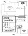
- FIG. 1is a functional block diagram of an exemplary system embodiment
- FIG. 2is a functional block diagram of an exemplary system controller
- FIG. 3is a flowchart depicting an exemplary process of the system controller
- FIG. 4is a functional block diagram of another exemplary system embodiment
- FIG. 5is a flowchart depicting an exemplary process of a subsystem controller of a local device.
- FIG. 6is a functional block diagram of another exemplary system embodiment.
- An energy management systemmonitors the output of energy generation devices in the system and energy consuming devices in the system. When the energy management system detects that energy generation exceeds the ability of the system to absorb that energy, the energy management system checks energy load devices in the system, e.g., appliances in the home, that may be engaged beyond their respective regulated cycling, to absorb the excess energy. The energy load devices may be evaluated and prioritized based on: the efficiency at which they can use this energy, the amount of energy they can absorb, and by user preference.
- the energy management systemmay then engage the loads to match the energy supply, and may do so based on the prioritized ranking of energy load devices in the system that are, as of yet, not engaged.
- Normal operating limits of the energy load devicesmay be set for maximum energy efficiency and the maximum operating limits of the load devices may be set for safety and user tolerance. So, when the difference between electricity generation and consumption returns to within a nominal range, such that this exceptional state is not required, the appliances that have absorbed this excess energy may then draw on this energy, via the delay of their respective next on-cycle, that may be extended with the re-application of their normal, or nominal, set points.
- Examples of local regulated energy load devicesinclude: a water heater that has preheated the hot water supply; an air conditioner that has pre-cooled the living space; a battery storage system that has charged into a less efficient state of charge; a food refrigeration system that has pre-cooled food, but not cooled below freezing; and a food freezer that has super cooled the food therein.
- FIG. 1is a functional block diagram of an exemplary system 100 embodiment where a power source 110 provides power to a first local device 130 and a second local device 131 .
- the power source 110may comprise a local power source 111 and/or the general electrical utility grid 112 .
- a system controller 120may direct power from either source 111 , 112 , for example, via power switches, S 1 and S 2 .
- the system controller 120is configured to monitor local power generation level of the local power source 111 , and the power consumption levels of the local devices 130 , 131 . Based on the generation and consumption levels, the system controller 120 may effect a closing of the first power switch, S 1 , or a closing of the second power switch, S 2 .
- the system controller 120may effect a closing of a third power switch, S 3 , and thereby direct at least a portion of the power being generated by the local power source 111 to the grid 112 .
- Alternative embodiments to the exemplary power switches S 1 , S 2 , and S 3may include power control circuitry to manage by direction the flow of energy.
- the first local device 130is depicted as comprising a subsystem controller 140 and a power-consuming element 150 .
- the power-consuming element 150is depicted as effecting a change in the energy state of a target mass 132 .
- the energy state of the target mass 132is depicted as monitored by the subsystem controller 140 .
- the second local device 131is depicted as comprising a subsystem controller 160 and battery charging circuitry 170 .
- the battery charging circuitry 170is depicted as effecting a change in the energy state of a battery 133 .
- the energy state of the battery 133is depicted as monitored by the subsystem controller 160 of the second local device 131 .
- FIG. 2is a functional block diagram of an exemplary system controller 220 having a processor 224 and memory 227 addressable via a data bus 228 .
- a user interface 229a power source interface 221 , and an interface 226 by which one or more local devices may communicate with the processor 224 via the data bus 228 .
- the processor 224may be configured to execute programmed steps via a real-time operating system 225 where the steps that comprise the application 222 include energy consumption and/or energy production inputs that are taken or estimated, comparisons are made with load capabilities and priorities of engaging or disengaging load elements, and commands and/or values are sent to local devices for energy management.
- FIG. 3is a flowchart depicting an exemplary process of the system controller 300 .
- the system controllermay be provided or be pre-loaded with a set of one or more energy load priorities. Accordingly, the system controller may input one or more energy load priorities (step 310 ) associated with the local devices of the system.
- the system controlleris depicted in FIG. 3 as inputting (step 320 ) an energy supply level (ESL), i.e., the present level of generated energy available to the local devices under the control of the system controller.
- ESLenergy supply level
- the system controlleris also depicted as optionally inputting (step 330 ) or estimating the separate or combined energy level of dissipation (EDL), i.e., the combined energy consumption level, by the one or more active energy loads.
- ESLenergy supply level
- EDLseparate or combined energy level of dissipation
- An error margin, ⁇may be referenced to provide a hysteresis effect to the following exemplary switching logic.
- the system controllermay test (test 340 ) whether the ESL, less the marginal value of ⁇ , is greater than the EDL. If so, then the system controller may output a command to effect an engagement of an energy load, not already engaged, that is the load of highest priority—i.e., according to the set of energy load priorities (step 350 ). If not, the system controller may test (test 360 ) whether the ESL, less the marginal value of ⁇ , is less than or equal to the EDL. If so, then the system controller may output a command to effect a disengagement of a load (step 370 ), not already disengaged, that is the energy load of lowest priority—according to the set of energy load priorities.
- FIG. 4is a functional block diagram of an exemplary system embodiment 400 comprising a power source 410 , a system controller 420 , a local device 430 , a target mass 432 , and a temperature sensor 490 .
- the local energy load device 430is depicted as comprising a subsystem controller 440 and a refrigeration unit 450 .
- the system controlleris depicted as inputting the energy supply level (ESL) 411 of the power source 410 and the energy dissipation level (EDL) 412 as being drawn from the power source 410 by the local device 430 .
- ESLenergy supply level
- EDLenergy dissipation level
- the refrigeration unit 450effects a change in the energy state of the target mass 432 and the temperature of the target mass 432 is depicted as being measured by a temperature sensor 490 .
- the output of the temperature sensormay be provided to the subsystem control 440 , the system controller 420 , or both.
- the system controller 420may generate a command to override the local logic of the subsystem controller 440 to effect an engagement or a disengagement of the refrigeration unit 450 .
- the subsystem controller 440may have controller logic 441 , and the system controller 420 may generate a command to shift temperature settings 442 within the controller logic 441 .
- the system controller 420may send new temperature settings 442 , e.g., T′ off and T′ on .
- the system controller 420may send a signal to shift the temperature settings 442 to a stored set of temperature settings 442 , e.g., T off to T′ off and T on to T′ on .
- the system controller 420may send a reset signal to reset the temperature settings 442 , e.g., T′ off to T off and T′ on to T on .
- FIG. 5is a flowchart depicting an exemplary process of a subsystem controller of a local device.
- the subsystem controllermay determine (test 510 ) whether it has received an engagement override signal, and if so, the subsystem controller engages or disengages a load (step 520 ) based on information contained in the engagement signal.
- the subsystem controllermay determine (test 530 ) whether it has received a set point shift command, and if so, the subsystem controller shifts one or more set points (step 540 ) based on the information contained in the set point shift command signal.
- the subsystem controllermay determine (test 550 ) whether it has received an update signal for one or more set points, and if so, the subsystem controller replaces one or more received set point updates (step 560 ) based on the information contained in the set point update signal.
- FIG. 6is a functional block diagram of an exemplary system embodiment 600 comprising a power source 610 , a system controller 620 , a local energy load device 630 , and a chemical battery 643 or chemical battery array.
- a chemical battery 643 or chemical battery arrayIn place of, or in addition to, the chemical battery, other energy storage devices may be employed, such as kinetic (e.g., flywheel) systems and/or pneumatic (e.g., pressure exchange) systems.
- the local energy load device 630is depicted as comprising a subsystem controller 660 and a charging circuit 670 .
- the system controlleris depicted as inputting the energy supply level (ESL) 611 of the power source 610 and the energy dissipation level (EDL) 612 as power is being drawn from the power source 610 by the local device 630 .
- the EDL 612may be estimated or a nominal value for each energy load device may be referenced for combination as the EDL 612 .
- the charging circuit 670effects a change in the energy state of the chemical battery 643 , and the temperature of the chemical battery 643 is depicted as being measured by a temperature sensor 675 .
- the output of the temperature sensor 675may be provided to the subsystem controller 660 , the system controller 620 , or both.
- the system controller 620may generate a command to override the local logic of the subsystem controller 660 to effect an engagement or a disengagement of the charging circuit 670 .
- the subsystem controller 660may include: a regulator set point 661 that may be preset or overwritten by the system controller 620 ; and a first current reference value 663 , I ref , a second current reference value 664 , I′ ref , and a logical switch 662 that may be set via a command signal from the system controller 620 .
- the subsystem controller 660may also include a first voltage reference value 665 , V ref , a second voltage reference value 667 , V′ ref , and a second logical switch 666 that may be set via a command signal from the system controller 620 .
- the system controller 620may send a new regulator set point value and/or signals to effect the switching to the second current reference value 664 , I′ ref , and/or to effect the switching to the second voltage reference value 667 , V′ ref .
- the system controller 620may send replacement values for the current reference, I ref , and/or the voltage reference V ref .
- the system controller 620may send a signal to shift the regulator set point 661 to a preset value.
- the charging circuit 670is depicted as comprising a regulator 671 , a current controller 672 based on a reference current value, a voltage controller 674 bases on a reference voltage value, and the charging circuit 670 that may include the temperature sensor 675 .
Landscapes
- Engineering & Computer Science (AREA)
- Power Engineering (AREA)
- Supply And Distribution Of Alternating Current (AREA)
- Remote Monitoring And Control Of Power-Distribution Networks (AREA)
Abstract
Description
Claims (15)
Priority Applications (3)
| Application Number | Priority Date | Filing Date | Title |
|---|---|---|---|
| US12/817,468US8359125B2 (en) | 2010-06-17 | 2010-06-17 | Energy management system to reduce the loss of excess energy generation |
| JP2011123732AJP2012005342A (en) | 2010-06-17 | 2011-06-01 | Energy management device and method for the same |
| EP11004898AEP2398125A2 (en) | 2010-06-17 | 2011-06-15 | Device and method for energy management |
Applications Claiming Priority (1)
| Application Number | Priority Date | Filing Date | Title |
|---|---|---|---|
| US12/817,468US8359125B2 (en) | 2010-06-17 | 2010-06-17 | Energy management system to reduce the loss of excess energy generation |
Publications (2)
| Publication Number | Publication Date |
|---|---|
| US20110313585A1 US20110313585A1 (en) | 2011-12-22 |
| US8359125B2true US8359125B2 (en) | 2013-01-22 |
Family
ID=44653081
Family Applications (1)
| Application Number | Title | Priority Date | Filing Date |
|---|---|---|---|
| US12/817,468Expired - Fee RelatedUS8359125B2 (en) | 2010-06-17 | 2010-06-17 | Energy management system to reduce the loss of excess energy generation |
Country Status (3)
| Country | Link |
|---|---|
| US (1) | US8359125B2 (en) |
| EP (1) | EP2398125A2 (en) |
| JP (1) | JP2012005342A (en) |
Cited By (8)
| Publication number | Priority date | Publication date | Assignee | Title |
|---|---|---|---|---|
| US20120166008A1 (en)* | 2010-12-22 | 2012-06-28 | Electronics And Telecommunications Research Institute | Smart grid power controller and power control method for the same |
| US9519878B2 (en) | 2011-10-03 | 2016-12-13 | Microsoft Technology Licensing, Llc | Power regulation of power grid via datacenter |
| US9537313B2 (en) | 2012-12-07 | 2017-01-03 | Battelle Memorial Institute | Method and system for using demand side resources to provide frequency regulation using a dynamic allocation of energy resources |
| US9886316B2 (en) | 2010-10-28 | 2018-02-06 | Microsoft Technology Licensing, Llc | Data center system that accommodates episodic computation |
| US20180090939A1 (en)* | 2016-09-29 | 2018-03-29 | Tokitae Llc | Devices and methods for use 5 with refrigeration devices including temperature-controlled container systems |
| US9933804B2 (en) | 2014-07-11 | 2018-04-03 | Microsoft Technology Licensing, Llc | Server installation as a grid condition sensor |
| US10116136B2 (en) | 2015-03-19 | 2018-10-30 | Battelle Memorial Institute | Primary frequency control through simulated droop control with electric loads |
| US10234835B2 (en) | 2014-07-11 | 2019-03-19 | Microsoft Technology Licensing, Llc | Management of computing devices using modulated electricity |
Families Citing this family (9)
| Publication number | Priority date | Publication date | Assignee | Title |
|---|---|---|---|---|
| CA2762395C (en) | 2010-12-16 | 2018-09-04 | Lennox Industries Inc | Priority-based energy management |
| WO2013019990A1 (en)* | 2011-08-02 | 2013-02-07 | Power Assure, Inc. | System and method for using data centers as virtual power plants |
| US8774976B2 (en) | 2012-05-31 | 2014-07-08 | Sharp Laboratories Of America, Inc. | Method and system for reducing peak load charge on utility bill using target peak load and countermeasures |
| US8761949B2 (en) | 2012-05-31 | 2014-06-24 | Sharp Laboratories Of America, Inc. | Method and system for mitigating impact of malfunction in actual load determination on peak load management |
| ES2685910T3 (en)* | 2012-09-28 | 2018-10-15 | Enrichment Technology Company Ltd. | Energy storage system |
| ITPD20120389A1 (en)* | 2012-12-19 | 2014-06-20 | Enzo Bertoldi | METHOD OF ENERGY MANAGEMENT PRODUCED BY A PLANT FOR THE GENERATION OF ENERGY FROM RENEWABLE SOURCES |
| US9368968B2 (en)* | 2012-12-28 | 2016-06-14 | Younicos, Inc. | Responding to local grid events and distributed grid events |
| US10958099B2 (en)* | 2018-02-21 | 2021-03-23 | General Electric Technology Gmbh | Real-time electrical grid restoration |
| CN111509750B (en)* | 2020-04-27 | 2021-02-19 | 湖南经研电力设计有限公司 | Power grid side energy storage system capacity configuration optimization method |
Citations (18)
| Publication number | Priority date | Publication date | Assignee | Title |
|---|---|---|---|---|
| US4916328A (en)* | 1988-12-08 | 1990-04-10 | Honeywell Inc. | Add/shed load control using anticipatory processes |
| US6080927A (en) | 1994-09-15 | 2000-06-27 | Johnson; Colin Francis | Solar concentrator for heat and electricity |
| US20040128266A1 (en) | 2001-08-16 | 2004-07-01 | International Business Machines Corporation | Method for optimizing energy consumption and cost |
| US6889122B2 (en) | 1998-05-21 | 2005-05-03 | The Research Foundation Of State University Of New York | Load controller and method to enhance effective capacity of a photovoltaic power supply using a dynamically determined expected peak loading |
| US20050107892A1 (en)* | 2003-11-19 | 2005-05-19 | Matsushita Electric Industrial Co., Ltd. | Generator control system, generating apparatus control method, program and record medium |
| US20060036349A1 (en) | 2004-08-11 | 2006-02-16 | Lawrence Kates | Method and apparatus for load reduction in an electric power system |
| US7155320B2 (en) | 2001-12-11 | 2006-12-26 | General Electric Company | Distributed power delivery system |
| US7324876B2 (en) | 2001-07-10 | 2008-01-29 | Yingco Electronic Inc. | System for remotely controlling energy distribution at local sites |
| US20080040295A1 (en)* | 2006-08-10 | 2008-02-14 | V2 Green, Inc. | Power Aggregation System for Distributed Electric Resources |
| US7373222B1 (en)* | 2003-09-29 | 2008-05-13 | Rockwell Automation Technologies, Inc. | Decentralized energy demand management |
| US7460930B1 (en) | 2004-05-14 | 2008-12-02 | Admmicro Properties, Llc | Energy management system and method to monitor and control multiple sub-loads |
| US20090105888A1 (en) | 2007-11-08 | 2009-04-23 | Sequentric Energy Systems, Llc | Methods, circuits, and computer program products for generation following load management |
| US20090164393A1 (en) | 2006-02-15 | 2009-06-25 | Mitsubishi Electric Corporation | Power system stabilization system |
| US7565227B2 (en) | 2007-08-15 | 2009-07-21 | Constellation Energy Group, Inc. | Multi-building control for demand response power usage control |
| US20100017045A1 (en) | 2007-11-30 | 2010-01-21 | Johnson Controls Technology Company | Electrical demand response using energy storage in vehicles and buildings |
| US7702424B2 (en) | 2003-08-20 | 2010-04-20 | Cannon Technologies, Inc. | Utility load control management communications protocol |
| US20100138062A1 (en) | 2009-07-14 | 2010-06-03 | Danian Zheng | Method and systems for utilizing excess energy generated by a renewable power generation system to treat organic waste material |
| US20100138363A1 (en) | 2009-06-12 | 2010-06-03 | Microsoft Corporation | Smart grid price response service for dynamically balancing energy supply and demand |
- 2010
- 2010-06-17USUS12/817,468patent/US8359125B2/ennot_activeExpired - Fee Related
- 2011
- 2011-06-01JPJP2011123732Apatent/JP2012005342A/ennot_activeWithdrawn
- 2011-06-15EPEP11004898Apatent/EP2398125A2/ennot_activeWithdrawn
Patent Citations (18)
| Publication number | Priority date | Publication date | Assignee | Title |
|---|---|---|---|---|
| US4916328A (en)* | 1988-12-08 | 1990-04-10 | Honeywell Inc. | Add/shed load control using anticipatory processes |
| US6080927A (en) | 1994-09-15 | 2000-06-27 | Johnson; Colin Francis | Solar concentrator for heat and electricity |
| US6889122B2 (en) | 1998-05-21 | 2005-05-03 | The Research Foundation Of State University Of New York | Load controller and method to enhance effective capacity of a photovoltaic power supply using a dynamically determined expected peak loading |
| US7324876B2 (en) | 2001-07-10 | 2008-01-29 | Yingco Electronic Inc. | System for remotely controlling energy distribution at local sites |
| US20040128266A1 (en) | 2001-08-16 | 2004-07-01 | International Business Machines Corporation | Method for optimizing energy consumption and cost |
| US7155320B2 (en) | 2001-12-11 | 2006-12-26 | General Electric Company | Distributed power delivery system |
| US7702424B2 (en) | 2003-08-20 | 2010-04-20 | Cannon Technologies, Inc. | Utility load control management communications protocol |
| US7373222B1 (en)* | 2003-09-29 | 2008-05-13 | Rockwell Automation Technologies, Inc. | Decentralized energy demand management |
| US20050107892A1 (en)* | 2003-11-19 | 2005-05-19 | Matsushita Electric Industrial Co., Ltd. | Generator control system, generating apparatus control method, program and record medium |
| US7460930B1 (en) | 2004-05-14 | 2008-12-02 | Admmicro Properties, Llc | Energy management system and method to monitor and control multiple sub-loads |
| US20060036349A1 (en) | 2004-08-11 | 2006-02-16 | Lawrence Kates | Method and apparatus for load reduction in an electric power system |
| US20090164393A1 (en) | 2006-02-15 | 2009-06-25 | Mitsubishi Electric Corporation | Power system stabilization system |
| US20080040295A1 (en)* | 2006-08-10 | 2008-02-14 | V2 Green, Inc. | Power Aggregation System for Distributed Electric Resources |
| US7565227B2 (en) | 2007-08-15 | 2009-07-21 | Constellation Energy Group, Inc. | Multi-building control for demand response power usage control |
| US20090105888A1 (en) | 2007-11-08 | 2009-04-23 | Sequentric Energy Systems, Llc | Methods, circuits, and computer program products for generation following load management |
| US20100017045A1 (en) | 2007-11-30 | 2010-01-21 | Johnson Controls Technology Company | Electrical demand response using energy storage in vehicles and buildings |
| US20100138363A1 (en) | 2009-06-12 | 2010-06-03 | Microsoft Corporation | Smart grid price response service for dynamically balancing energy supply and demand |
| US20100138062A1 (en) | 2009-07-14 | 2010-06-03 | Danian Zheng | Method and systems for utilizing excess energy generated by a renewable power generation system to treat organic waste material |
Cited By (9)
| Publication number | Priority date | Publication date | Assignee | Title |
|---|---|---|---|---|
| US9886316B2 (en) | 2010-10-28 | 2018-02-06 | Microsoft Technology Licensing, Llc | Data center system that accommodates episodic computation |
| US20120166008A1 (en)* | 2010-12-22 | 2012-06-28 | Electronics And Telecommunications Research Institute | Smart grid power controller and power control method for the same |
| US9519878B2 (en) | 2011-10-03 | 2016-12-13 | Microsoft Technology Licensing, Llc | Power regulation of power grid via datacenter |
| US9537313B2 (en) | 2012-12-07 | 2017-01-03 | Battelle Memorial Institute | Method and system for using demand side resources to provide frequency regulation using a dynamic allocation of energy resources |
| US9933804B2 (en) | 2014-07-11 | 2018-04-03 | Microsoft Technology Licensing, Llc | Server installation as a grid condition sensor |
| US10234835B2 (en) | 2014-07-11 | 2019-03-19 | Microsoft Technology Licensing, Llc | Management of computing devices using modulated electricity |
| US10116136B2 (en) | 2015-03-19 | 2018-10-30 | Battelle Memorial Institute | Primary frequency control through simulated droop control with electric loads |
| US20180090939A1 (en)* | 2016-09-29 | 2018-03-29 | Tokitae Llc | Devices and methods for use 5 with refrigeration devices including temperature-controlled container systems |
| US10707683B2 (en)* | 2016-09-29 | 2020-07-07 | Tokitae Llc | Directing or modulating electrical power drawn by one or more loads from a solar photovoltaic module array while maintaining a buffer margin |
Also Published As
| Publication number | Publication date |
|---|---|
| JP2012005342A (en) | 2012-01-05 |
| EP2398125A2 (en) | 2011-12-21 |
| US20110313585A1 (en) | 2011-12-22 |
Similar Documents
| Publication | Publication Date | Title |
|---|---|---|
| US8359125B2 (en) | Energy management system to reduce the loss of excess energy generation | |
| CN106816884B (en) | energy storage system | |
| CN105071415B (en) | Micro-grid energy adjusting method and system | |
| JP5663645B2 (en) | Control apparatus and control method | |
| US8413035B2 (en) | Power control apparatus and method for realizing efficient load factor with lower contracted power limit | |
| WO2012049965A1 (en) | Power management system | |
| CN111628519A (en) | Power supply control method of power supply system, power supply system and storage medium | |
| US20190296577A1 (en) | Control approach for power modulation of end-use loads | |
| KR102004332B1 (en) | Cell balancing method and apparatus for performing active balancing and passive balancing simultaneously and energy storage system using the same | |
| US9746861B2 (en) | Stand-alone DC power system for networks not connected to the grid | |
| WO2017120331A1 (en) | Method and apparatus for coordination of generators in droop controlled microgrids using hysteresis | |
| KR20120017930A (en) | Recording medium storing power storage system, control method thereof and program for executing same | |
| KR20190085094A (en) | Conversion circuit devices for uninterruptible power supply (UPS) systems | |
| WO2020211487A1 (en) | Temperature control method and device for energy storage device | |
| JP2000295784A (en) | Power storage system | |
| Cheng et al. | Primary frequency response in the Great Britain power system from dynamically controlled refrigerators | |
| Lu et al. | Passive energy storage using distributed electric loads with thermal storage | |
| JP6047929B2 (en) | Battery control device | |
| CN108332463B (en) | Control method and system of air-conditioning cabinet between batteries of data center | |
| CN118157181A (en) | Energy storage system power supply method, device, equipment, medium and product | |
| WO2012049973A1 (en) | Power management system | |
| AU2017101651A4 (en) | Systems for supplying power to a grid | |
| CN115313372A (en) | Building and its power system and power supply method, air conditioning equipment and its control method | |
| JP2009105998A (en) | Power storage device | |
| US20210159699A1 (en) | Improved method for managing a group of electrical devices |
Legal Events
| Date | Code | Title | Description |
|---|---|---|---|
| AS | Assignment | Owner name:SHARP LABORATORIES OF AMERICA, INC., WASHINGTON Free format text:ASSIGNMENT OF ASSIGNORS INTEREST;ASSIGNOR:PARK, DANIEL J.;REEL/FRAME:024577/0348 Effective date:20100616 | |
| STCF | Information on status: patent grant | Free format text:PATENTED CASE | |
| AS | Assignment | Owner name:SHARP KABUSHIKI KAISHA, JAPAN Free format text:ASSIGNMENT OF ASSIGNORS INTEREST;ASSIGNOR:SHARP LABORATORIES OF AMERICA, INC.;REEL/FRAME:030350/0730 Effective date:20130214 | |
| FEPP | Fee payment procedure | Free format text:PAYOR NUMBER ASSIGNED (ORIGINAL EVENT CODE: ASPN); ENTITY STATUS OF PATENT OWNER: LARGE ENTITY | |
| FPAY | Fee payment | Year of fee payment:4 | |
| AS | Assignment | Owner name:SHARP ELECTRONICS CORPORATION, NEW JERSEY Free format text:ASSIGNMENT OF ASSIGNORS INTEREST;ASSIGNOR:SHARP KABUSHIKI KAISHA (SHARP CORPORATION);REEL/FRAME:047596/0223 Effective date:20181101 | |
| AS | Assignment | Owner name:NANTENERGY, INC., CALIFORNIA Free format text:ASSIGNMENT OF ASSIGNORS INTEREST;ASSIGNOR:SHARP ELECTRONICS CORPORATION;REEL/FRAME:047789/0215 Effective date:20181106 | |
| MAFP | Maintenance fee payment | Free format text:PAYMENT OF MAINTENANCE FEE, 8TH YEAR, LARGE ENTITY (ORIGINAL EVENT CODE: M1552); ENTITY STATUS OF PATENT OWNER: LARGE ENTITY Year of fee payment:8 | |
| FEPP | Fee payment procedure | Free format text:MAINTENANCE FEE REMINDER MAILED (ORIGINAL EVENT CODE: REM.); ENTITY STATUS OF PATENT OWNER: LARGE ENTITY | |
| LAPS | Lapse for failure to pay maintenance fees | Free format text:PATENT EXPIRED FOR FAILURE TO PAY MAINTENANCE FEES (ORIGINAL EVENT CODE: EXP.); ENTITY STATUS OF PATENT OWNER: LARGE ENTITY | |
| STCH | Information on status: patent discontinuation | Free format text:PATENT EXPIRED DUE TO NONPAYMENT OF MAINTENANCE FEES UNDER 37 CFR 1.362 | |
| FP | Lapsed due to failure to pay maintenance fee | Effective date:20250122 |