US8358644B2 - Methods and apparatus for generating synchronization/pilot sequences for embedding in wireless signals - Google Patents
Methods and apparatus for generating synchronization/pilot sequences for embedding in wireless signalsDownload PDFInfo
- Publication number
- US8358644B2 US8358644B2US12/051,535US5153508AUS8358644B2US 8358644 B2US8358644 B2US 8358644B2US 5153508 AUS5153508 AUS 5153508AUS 8358644 B2US8358644 B2US 8358644B2
- Authority
- US
- United States
- Prior art keywords
- synchronization
- pilot sequences
- sps
- candidate
- pilot
- Prior art date
- Legal status (The legal status is an assumption and is not a legal conclusion. Google has not performed a legal analysis and makes no representation as to the accuracy of the status listed.)
- Expired - Fee Related, expires
Links
- 238000000034methodMethods0.000titleclaimsabstractdescription96
- 238000004891communicationMethods0.000claimsdescription31
- 230000009466transformationEffects0.000claimsdescription17
- 238000000819phase cycleMethods0.000claimsdescription14
- 238000012937correctionMethods0.000claimsdescription12
- 230000000875corresponding effectEffects0.000claimsdescription10
- 230000002596correlated effectEffects0.000claimsdescription6
- 230000001413cellular effectEffects0.000claimsdescription3
- 230000010363phase shiftEffects0.000description24
- 230000009467reductionEffects0.000description22
- 238000001514detection methodMethods0.000description11
- 230000008569processEffects0.000description11
- 230000005540biological transmissionEffects0.000description8
- 239000000969carrierSubstances0.000description8
- 238000010586diagramMethods0.000description8
- 230000001965increasing effectEffects0.000description8
- 108010046685Rho FactorProteins0.000description6
- 238000005562fadingMethods0.000description6
- 238000003860storageMethods0.000description6
- 230000000694effectsEffects0.000description5
- 238000013507mappingMethods0.000description5
- 230000004044responseEffects0.000description5
- 238000012549trainingMethods0.000description5
- 238000000844transformationMethods0.000description5
- 238000006243chemical reactionMethods0.000description4
- 238000012545processingMethods0.000description4
- 239000000654additiveSubstances0.000description3
- 230000000996additive effectEffects0.000description3
- 230000008901benefitEffects0.000description3
- 230000003247decreasing effectEffects0.000description3
- 230000001419dependent effectEffects0.000description3
- 238000013461designMethods0.000description3
- 230000006870functionEffects0.000description3
- 238000005457optimizationMethods0.000description3
- 230000003595spectral effectEffects0.000description3
- 230000003321amplificationEffects0.000description2
- 230000000295complement effectEffects0.000description2
- 230000003750conditioning effectEffects0.000description2
- 230000001186cumulative effectEffects0.000description2
- 125000004122cyclic groupChemical group0.000description2
- 230000007423decreaseEffects0.000description2
- 238000005315distribution functionMethods0.000description2
- 238000001914filtrationMethods0.000description2
- 238000003199nucleic acid amplification methodMethods0.000description2
- 239000002245particleSubstances0.000description2
- 230000000717retained effectEffects0.000description2
- 230000002441reversible effectEffects0.000description2
- 230000002411adverseEffects0.000description1
- 238000013459approachMethods0.000description1
- 230000015572biosynthetic processEffects0.000description1
- 230000008859changeEffects0.000description1
- 230000001627detrimental effectEffects0.000description1
- 229910003460diamondInorganic materials0.000description1
- 239000010432diamondSubstances0.000description1
- 238000005516engineering processMethods0.000description1
- 230000007717exclusionEffects0.000description1
- PCHJSUWPFVWCPO-UHFFFAOYSA-NgoldChemical compound[Au]PCHJSUWPFVWCPO-UHFFFAOYSA-N0.000description1
- 239000010931goldSubstances0.000description1
- 229910052737goldInorganic materials0.000description1
- 230000001939inductive effectEffects0.000description1
- 238000004519manufacturing processMethods0.000description1
- 238000005259measurementMethods0.000description1
- 230000003287optical effectEffects0.000description1
- 230000002829reductive effectEffects0.000description1
- 238000011160researchMethods0.000description1
- 238000005070samplingMethods0.000description1
- 230000011218segmentationEffects0.000description1
- 238000001228spectrumMethods0.000description1
- 238000003786synthesis reactionMethods0.000description1
- 230000002123temporal effectEffects0.000description1
Images


Classifications
- H—ELECTRICITY
- H04—ELECTRIC COMMUNICATION TECHNIQUE
- H04B—TRANSMISSION
- H04B1/00—Details of transmission systems, not covered by a single one of groups H04B3/00 - H04B13/00; Details of transmission systems not characterised by the medium used for transmission
- H04B1/59—Responders; Transponders
- H—ELECTRICITY
- H04—ELECTRIC COMMUNICATION TECHNIQUE
- H04L—TRANSMISSION OF DIGITAL INFORMATION, e.g. TELEGRAPHIC COMMUNICATION
- H04L27/00—Modulated-carrier systems
- H04L27/26—Systems using multi-frequency codes
- H04L27/2601—Multicarrier modulation systems
- H04L27/2602—Signal structure
- H04L27/261—Details of reference signals
- H04L27/2613—Structure of the reference signals
- H—ELECTRICITY
- H04—ELECTRIC COMMUNICATION TECHNIQUE
- H04L—TRANSMISSION OF DIGITAL INFORMATION, e.g. TELEGRAPHIC COMMUNICATION
- H04L27/00—Modulated-carrier systems
- H04L27/26—Systems using multi-frequency codes
- H04L27/2601—Multicarrier modulation systems
- H04L27/2614—Peak power aspects
- H04L27/262—Reduction thereof by selection of pilot symbols
- H—ELECTRICITY
- H04—ELECTRIC COMMUNICATION TECHNIQUE
- H04L—TRANSMISSION OF DIGITAL INFORMATION, e.g. TELEGRAPHIC COMMUNICATION
- H04L27/00—Modulated-carrier systems
- H04L27/26—Systems using multi-frequency codes
- H04L27/2601—Multicarrier modulation systems
- H04L27/2626—Arrangements specific to the transmitter only
- H—ELECTRICITY
- H04—ELECTRIC COMMUNICATION TECHNIQUE
- H04L—TRANSMISSION OF DIGITAL INFORMATION, e.g. TELEGRAPHIC COMMUNICATION
- H04L5/00—Arrangements affording multiple use of the transmission path
- H04L5/0001—Arrangements for dividing the transmission path
- H04L5/0003—Two-dimensional division
- H04L5/0005—Time-frequency
- H04L5/0007—Time-frequency the frequencies being orthogonal, e.g. OFDM(A) or DMT
- H—ELECTRICITY
- H04—ELECTRIC COMMUNICATION TECHNIQUE
- H04L—TRANSMISSION OF DIGITAL INFORMATION, e.g. TELEGRAPHIC COMMUNICATION
- H04L5/00—Arrangements affording multiple use of the transmission path
- H04L5/003—Arrangements for allocating sub-channels of the transmission path
- H04L5/0048—Allocation of pilot signals, i.e. of signals known to the receiver
- H—ELECTRICITY
- H04—ELECTRIC COMMUNICATION TECHNIQUE
- H04L—TRANSMISSION OF DIGITAL INFORMATION, e.g. TELEGRAPHIC COMMUNICATION
- H04L27/00—Modulated-carrier systems
- H04L27/26—Systems using multi-frequency codes
- H04L27/2601—Multicarrier modulation systems
- H04L27/2602—Signal structure
- H04L27/261—Details of reference signals
- H04L27/2613—Structure of the reference signals
- H04L27/26134—Pilot insertion in the transmitter chain, e.g. pilot overlapping with data, insertion in time or frequency domain
- H—ELECTRICITY
- H04—ELECTRIC COMMUNICATION TECHNIQUE
- H04L—TRANSMISSION OF DIGITAL INFORMATION, e.g. TELEGRAPHIC COMMUNICATION
- H04L27/00—Modulated-carrier systems
- H04L27/26—Systems using multi-frequency codes
- H04L27/2601—Multicarrier modulation systems
- H04L27/2647—Arrangements specific to the receiver only
- H04L27/2655—Synchronisation arrangements
- H04L27/2662—Symbol synchronisation
Definitions
- the inventive subject mattergenerally relates to methods and apparatus for wirelessly communicating signals, and more particularly to methods and apparatus for generating synchronization/pilot sequences and wirelessly communicating signals in which the synchronization/pilot sequences are embedded.
- Orthogonal frequency division multiplexingis a modulation method used in traditional, high-speed wireless networks.
- waveforms generated using traditional OFDM techniquesexhibit noise-like properties, and thus OFDM waveforms tend to suffer from relatively large peak-to-average ratios (PARs), which in turn may lead to significant distortion noise and low power efficiency in peak-limited channels.
- PARspeak-to-average ratios
- transmitted OFDM signalstend to incur significant timing offsets and carrier frequency offsets. Because traditional OFDM techniques tend not to be robust under harsh channel conditions, significant timing offsets may result in inter-block interference, and significant carrier frequency offsets may result in inter-carrier interference. Both of these forms of interference are detrimental to the bit error rates of received signals.
- some traditional OFDM devicestransmit a preamble in conjunction with and preceding an information-bearing OFDM sequence.
- the receivermay perform a conjugate correlation of the received preamble and an expected preamble to determine estimates for the timing and carrier frequency offsets.
- the preamblealso includes channel training information
- the preamblealso may be used to perform channel estimation.
- the channel estimatenaturally has some error, when compared with actual channel conditions.
- Traditional OFDM transmission methodsmay experience an increase in channel estimation errors on the receiver side, which may result from non-linear amplification, by a power amplifier device on the transmitter side, of transmit information sequences having higher than desired PARs.
- Such non-linear transmissionmay cause significant out-of-band interference (i.e., interference outside the signal bandwidth, such as in the adjacent channels and/or other user channels), and also may induce undesired in-band interference, which adds distortion the transmitted information bits and also to the channel training information.
- improper synthesis of the channel training informationmay lead to further channel estimation errors at the receiver.
- non-linear amplification of high peak-to-average power ratio signals and improper channel training information designmay, in the receiver, result in unacceptably high channel estimation errors and excessively high bit error rates.
- an information-bearing OFDM sequenceprior to transmission, is combined with a synchronization/pilot sequence, which provides spectral efficiency improvements over preamble-based synchronization approaches.
- Traditional sequencesinclude, for example, Pseudorandom Number (PN) sequences, Gold codes, Kasami codes, and m-sequences.
- PNPseudorandom Number
- traditional synchronization/pilot sequencesare appropriate for some situations, they do not provide for adequate system performance in other situations.
- traditional sequencesare designed to perform relatively well for synchronization purposes, they are not designed to provide low PAR or flat frequency response in conjunction with optimal channel estimation by the receiver.
- traditional synchronization/pilot sequencesdo not provide for adequate system performance in channel environments in which significant timing offsets, carrier frequency offsets, and multi-path fading effects simultaneously are present.
- FIG. 1is a simplified block diagram of a multi-carrier communication system that includes multiple wireless communication devices that communicate over a wireless communication channel, in accordance with an example embodiment
- FIG. 2is a simplified block diagram of a channel model, in accordance with an example embodiment
- FIG. 3is a simplified block diagram of a transmitter, in accordance with an example embodiment
- FIG. 4is an example of a frequency-domain representation of a transmitted signal, in accordance with an example embodiment
- FIG. 5is a simplified block diagram of a receiver, in accordance with an example embodiment
- FIG. 6is a flowchart of a method for generating a set of synchronization/pilot sequences (SPS), in accordance with an example embodiment
- FIG. 7is a flowchart of a method for generating and transmitting wireless signals that include embedded SPS, in accordance with an example embodiment
- FIG. 8is a flowchart of a method for receiving and processing wireless signals that include embedded SPS, in accordance with an example embodiment
- FIG. 9is a chart plotting relationships between an embedding factor representing a ratio of SPS power to signal power, and a ratio of pilot power to the total SPS power for various ratios of pilot to data subcarriers using three example embodiments;
- FIG. 10is a chart plotting bit error rate (BER) performance that may be achieved using two example embodiments
- FIG. 11is a chart indicating acquisition performance for a system employing an embodiment versus a system that uses traditional binary sequences
- FIG. 12is a chart indicating channel estimation performance for a system using SPS generated according to an embodiment and a system that uses traditional binary sequences;
- FIG. 13is a chart illustrating a complementary cumulative distribution function (CCDF) of the peak-to-average ratio (PAR) for signals produced using two different embedding sequences and various embedding factors, in accordance with example embodiments;
- CCDFcomplementary cumulative distribution function
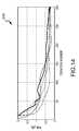
- FIG. 14is a plot of the convergence characteristics of the PAR for five lowest-PAR SPS, which were generated according to an embodiment.
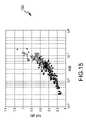
- FIG. 15is a scatter plot of the PAR and mean square error (MSE) after 600 iterations of an embodiment of a method for SPS generation for 150 different initial conditions.
- MSEmean square error
- Embodimentsinclude methods and apparatus for wirelessly communicating orthogonal frequency division multiplexing (OFDM) signals between wireless communication devices.
- a signal communicated according to an embodimentincludes an embedded synchronization/pilot sequence (SPS) selected from a set of SPS that is accessible to a transmitter and a receiver, as will be described in detail below.
- SPSembedded synchronization/pilot sequence
- the acronym SPSmay indicate a single synchronization/pilot sequence or multiple synchronization/pilot sequences.
- the term “set of SPS”means a set of multiple synchronization/pilot sequences.
- Embodimentsinclude methods for generating SPS that may have one or more significant advantages over traditional techniques. More particularly, embodiments of methods for generating sets of SPS that may jointly provide for robust synchronization, low peak-to-average ratios (PARs), and accurate channel estimation, among other things.
- SPS generated according to various embodimentsmay have synchronization properties (e.g., compensation for timing offsets and frequency offsets) that are comparable to and potentially better than for synchronization/pilot sequences generated using traditional techniques.
- low PARsmay be achieved because embodiments may enable a transmitter's power amplifier to be operated more efficiently.
- Improved channel estimationmay be achieved because SPS may be generated, according to various embodiments, using arbitrary frequency domain profiles while achieving a relatively flat frequency response over all frequencies of interest to the signal.
- embodimentsmay result in increased link ranges, because signals may be transmitted using lower power, and correspondingly may be less susceptible to detection. Conversely, embodiments may result in higher link margins, as it may be possible to transmit higher-power signals using a given power amplifier, when compared to traditional techniques that utilize non-constant envelope transmissions. In addition, for battery-powered apparatus, improved battery life may be achieved, because the power amplifier may be operated at a higher efficiency than using traditional techniques. Embodiments may lead to higher power amplifier efficiency, as a signal that includes an SPS generated according to an embodiment may require substantially less back-off than a system that utilizes traditional synchronization/pilot sequences.
- Embodimentsmay be utilized in various types of systems. For example, embodiments may be utilized in multi-carrier communication systems, single-carrier communication systems, and spread spectrum communication systems. Although embodiments discussed in detail below may pertain to a multi-carrier communication system, it is to be understood that other embodiments may apply to other types of systems, as well. Further, as will be explained in more detail below, embodiments include methods for generating a single SPS or for generating a set of SPS. Embodiments include embedded synchronization methods and apparatus that are employed in a selected mapping (SLM) system, and accordingly such embodiments may be referred to herein as SPS-SLM. It is to be understood that other embodiments may apply to systems in which selected mapping techniques are not employed.
- SLMselected mapping
- FIG. 1is a simplified block diagram of a multi-carrier communication system 100 that includes multiple wireless communication devices 102 , 104 that communicate over a wireless communication channel 106 , in accordance with an example embodiment.
- Multi-carrier communication system 100may be, for example but not by way of limitation, a currently existing or future multi-carrier based, ultra-wideband system, an OFDM multiple access system, a multi-carrier code division multiple access (MC-CDMA) system, a digital video broadcasting system, a WiMax (long range broadband wireless) system, a wireless local area network (WiLAN) system (e.g., an 802.11a system), and/or a number of other types of multi-carrier communication systems.
- WiMaxlong range broadband wireless
- WiLANwireless local area network
- Wireless communication devices 102 , 104may include, for example but not by way of limitation, a device selected from a group of devices comprising a cellular telephone, a radio, a one-way or two-way pager, a personal data assistant, a computer (e.g., a laptop or desktop computer), a base station, an unmanned autonomous vehicle, a wireless transmitter, and/or a wireless transceiver.
- a deviceselected from a group of devices comprising a cellular telephone, a radio, a one-way or two-way pager, a personal data assistant, a computer (e.g., a laptop or desktop computer), a base station, an unmanned autonomous vehicle, a wireless transmitter, and/or a wireless transceiver.
- Embodimentsmay be implemented in wireless communication devices 102 , 104 that include both a transmitter 110 , 112 and a receiver 114 , 116 (e.g., each device 102 , 104 includes a transceiver).
- transmitter 110 in a first device 102may receive an input data symbol 118 , X[n], and may generate and transmit, over channel 106 , a wireless signal 120 , y[n], which represents the input data symbol 118 .
- Receiver 114 in a second device 104may receive a channel-affected version 122 , z[n], of the wireless signal 120 , and may generate an output data symbol 124 , ⁇ circumflex over (X) ⁇ [n], representing an estimate of the input data symbol 118 .
- transmitter 112 in the second device 104may receive another input data symbol 130 , and may generate and transmit, over channel 106 , a wireless signal 132 representing the input data symbol.
- Receiver 116 in the first device 102may receive a channel-affected version 134 of the wireless signal 132 , and may generate an output data symbol 136 representing an estimate of the input data symbol 130 .
- system 100may provide for one-way communications.
- one devicemay include a transmitter (and no receiver) and another device may include a receiver (and no transmitter).
- one-way communications between a transmitter 110 in a first device 102 and a receiver 114 in a second device 104is described in detail in the remainder of this description. It is to be understood that the various embodiments also apply to two-way communications as well.
- transmitter 110is adapted to apply multiple phase shifts to an input data symbol 118 , and to combine a plurality of SPS, which are selected from a set of SPS accessible to transmitter 110 , with the phase shifted input data in order to produce a plurality of candidate signals.
- Embodiments of methods for generating SPSwill be described in more detail later in conjunction with FIG. 6 .
- First and second scaling factorsmay be applied to the input data symbol and to the plurality of SPS, respectively, prior to combining the phase shifted input data and the plurality of SPS.
- Transmitter 110also is adapted to determine PARs for at least some of the candidate signals, and to identify a selected candidate signal based on the PARs (e.g., the selected candidate signal may be the candidate signal with the lowest PAR). Transmitter 110 also is adapted to transmit a wireless signal 120 representing the selected candidate signal over the wireless communication channel 106 .
- Receiver 114is adapted to receive a channel-affected version 122 of the wireless signal 120 from the wireless communication channel 106 . Receiver 114 also is adapted to determine estimated channel perturbations within the channel-affected signal 122 based on its knowledge of the plurality of SPS, and to apply corrections to the channel-affected signal 122 , based on the estimated channel perturbations. Receiver 114 also is adapted to produce the output data symbol 132 based on the corrected signal, which represents an estimate of the input data symbol 130 processed at the transmitter 110 .
- a wireless signal transmitted over a channelmay be adversely affected by the channel, and a receiver that receives a channel-affected version of the transmitted signal may attempt to determine and correct for estimated channel perturbations reflected within the channel-affected signal.
- the channel perturbations generated by channel 106may not be the same for signals from transmitter 110 to receiver 114 as compared to a transmission from transmitter 112 to receiver 116 .
- a number of factorsmay induce differences in the forward and reverse directions. For example, when either or both devices 102 , 104 are mobile, channel 106 will be time variant, and the time that transmitter 110 transmits to receiver 114 may be different from the time than transmitter 112 may transmit to receiver 116 .
- the channel 106will be different depending on the transmit time for each transmitter 110 , 112 .
- the channel 106itself may have different characteristics in the forward direction as compared to the reverse direction. These differences may be induced by a number of factors which include, for example, device 102 possessing a transmit/receive antenna having different characteristics from the transmit/receive antenna of device 104 , and/or the local scattering environment being different for each device 102 , 104 , among other things.
- a simplified channel modelwill now be described.
- FIG. 2is a simplified block diagram of a channel model 200 , in accordance with an example embodiment.
- channel model 200illustrates various channel characteristics that may affect (e.g., perturb) a signal transmitted over the channel, and more particularly an unsynchronized mobile channel that communicates signals generated by a peak power-constrained system. These characteristics include, for example, a multi-path fading component 202 (which, in the frequency domain, manifests itself as frequency selective fading), a timing offset (TO) component 204 , a carrier frequency offset (CFO) component 206 , and an additive noise component 208 .
- TOtiming offset
- CFOcarrier frequency offset
- additive noise component 208an additive noise component 208 .
- the input-to-output characteristic of the transmitter's power amplifiere.g., power amplifier 316 , FIG.
- FIG. 3is a simplified block diagram of a transmitter 300 , in accordance with an example embodiment.
- Transmitter 300includes a data/scaling factor combiner 302 , a plurality of phase shifters 304 , a plurality of SPS/scaling factor combiners 306 , a plurality of data/SPS combiners 308 , a plurality of frequency domain-to-time domain (FD-to-TD) transformers 310 , a signal selector 312 , an up-converter 314 , a power amplifier 316 , and an antenna 318 operatively coupled together as illustrated in FIG. 3 , in an embodiment.
- FD-to-TDfrequency domain-to-time domain
- Data/scaling factor combiner 302includes computational apparatus adapted to receive a sequence of input data symbols 320 , X k , each of which represents a data-bearing part of a signal to be transmitted.
- X kis drawn from a finite constellation.
- Data/scaling factor combiner 302is further adapted to apply a first scaling factor 322 to an input data symbol 320 in order to produce a scaled input data symbol 324 .
- the first scaling factor 322has a value of ⁇ square root over (1 ⁇ ) ⁇ , where ⁇ is an embedding factor having a value between 0 and 1.
- the embedding factorrepresents a ratio of SPS power to signal power, which may be represented as
- the embedding factorhas a value in a range of about 0.25 to about 0.35. In another embodiment, the embedding factor has a value in a range of about 0.2 to about 0.4. In still other embodiments, the embedding factor may have higher or lower values than the above-given ranges.
- the scaled input data symbol 342may be represented as ⁇ square root over (1 ⁇ ) ⁇ X k .
- Each of the plurality of phase shifters 304includes computational apparatus adapted to apply a different phase shift 326 ,
- Dis a value referred to herein as a candidate number quantity
- dis an index referred to herein as a relational index
- d ⁇ 1, 2, . . . , D ⁇The candidate number quantity, D, may be selected as any integer number from 1 to 16, in an embodiment, although the candidate number quantity may be a larger number, in other embodiments. In a particular embodiment, the candidate number quantity is selected as an integer number between 3 and 10.
- the number of phase shifted input data signals 328 producedequals the candidate number quantity D, although the number of phase shifted input data signals 328 may be different, in other embodiments.
- the different phase shifts 326may be represented within entries of a table of phase shift values, in an embodiment, and the relational index, d, may be used an index into the phase shift value table, among other things. Accordingly, the phase shift value table may have D entries, in an embodiment, although the phase shift value table may have more or fewer entries in other embodiments. Transmitter 300 also is adapted to obtain a plurality of SPS 332 , S k (d) , each of which represents a unique synchronization/pilot sequence.
- the plurality of SPS 332may be obtained from a table of SPS, which is accessible to or stored in transmitter 300 , and which includes one or more sets of pre-generated SPS, each of which may be referenced by a unique index (referred to below as an SLM index).
- SLM indexa unique index
- Each SPS 332 in the transmitter's SPS tableis represented in the frequency domain, in an embodiment. Embodiments of methods for generating sets of SPS will be described in more detail later in conjunction with FIG. 6 .
- SPS/scaling factor combiners 306include computational apparatus adapted to apply second scaling factors 330 to the plurality of SPS 332 in order to produce a plurality of scaled SPS 334 , ⁇ square root over ( ⁇ ) ⁇ S k (d) , where d is the relational index. Similar to its functionality with respect to the phase shift value table, the relational index, d, also may be used an index into the SPS table. When used in this context, the relational index alternatively may be referred to as an SLM index. As with the phase shift value table, the SPS table also may have D entries, although the SPS table may have more or fewer entries in other embodiments. In addition, in an embodiment, the number of scaled SPS 334 produced equals the candidate number quantity D, although the number of SPS 334 may be different, in other embodiments.
- each different phase shift value 326may be related to a unique SPS 332 via the relational index, d.
- a particular phase shift value 326may be related to multiple unique SPS 332 , or a particular unique SPS 332 may be related to multiple phase shift values 326 (e.g., by including duplicate values in the phase shift value table or the SPS table, for example).
- the second scaling factor 330has a value of ⁇ square root over ( ⁇ ) ⁇ , where ⁇ is the same embedding factor as the embedding factor incorporated in the first scaling factor 322 .
- the value of the embedding factor, ⁇dictates how much relative signal power is allocated to a data-bearing component, X k (d) , of a transmitted signal as opposed to an SPS component, S k (d) , of the transmitted signal.
- Phase shifters 304provide the plurality of phase shifted input data signals 328 to data/SPS combiners 308
- SPS/scaling factor combiners 306provide the plurality of scaled SPS 334 to data/SPS combiners 308
- Each of data/SPS combiners 308includes computational apparatus adapted to combine one of the plurality of phase shifted input data signals 328 with one of the scaled SPS 334 in order to produce a plurality of combined signals 340 , where the plurality of combined signals 340 may be represented in the frequency domain by the equation:
- the number of combined signals 340 producedequals the candidate number quantity D, although the number of combined signals 340 may be different, in other embodiments.
- Data/SPS combiners 308provide the plurality of combined signals 340 to FD-to-TD transformers 310 .
- FD-to-TD transformers 310include computational apparatus adapted to perform frequency domain-to-time domain transformations on each of the combined signals 340 , in order to produce a plurality of candidate signals 342 , y (d) [n].
- the number of candidate signals 342 producedequals the candidate number quantity D, although the number of candidate signals 342 may be different, in other embodiments.
- the frequency domain-to-time domain transformationmay include an inverse Fourier transform (IFT) or, more particularly, an inverse discrete Fourier transform (IDFT), in various embodiments, although other types of frequency domain-to-time domain transformations may be performed in other embodiments.
- IFTinverse Fourier transform
- IDFTinverse discrete Fourier transform
- x (d) [n]IDFT ⁇ X k e j ⁇ h (d) ⁇
- s (d) [n]IDFT ⁇ S k (d) ⁇
- n ⁇ 0, 1, . . . , N ⁇ 1 ⁇an efficient algorithm for computing the inverse discrete Fourier transform (IDFT) may be implemented, such as an inverse fast Fourier transform (IFFT), for example.
- IFFTinverse fast Fourier transform
- transmitter 300includes a number of phase shifters 304 , a number of SPS/scaling factor combiners 330 , a number of data/SPS combiners 308 , and a number of FD-to-TD transformers 310 that is equal to the candidate number quantity, D, and that these transmitter elements are adapted to generate a same number, D, of phase shifted input data signals 328 , scaled SPS 334 , combined signals 340 , and candidate signals 342 , respectively.
- transmitter 300may include more or fewer than the candidate number quantity, D, of phase shifters 304 , SPS/scaling factor combiners 330 , data/SPS combiners 308 , and/or FD-to-TD transformers 310 , and/or some or all of these transmitter elements may be adapted to generate more or fewer than the candidate number quantity, D, of phase shifted input data signals 328 , scaled SPS 334 , combined signals 340 , and/or candidate signals 342 , respectively.
- phase shifters 304may be the same, in an embodiment, in other embodiments, the numbers of these transmitter components 304 , 330 , 308 , 310 and/or signals 328 , 334 , 340 , 342 may be different.
- data/SPS combiners 308may combine a same phase shifted input data signal 328 with multiple scaled SPS 334 or data/SPS combiners 308 may combine a same scaled SPS 334 with multiple phase shifted input data signals 328 , in various embodiments.
- some signalsmay be disregarded when, for example, they fail to meet certain criteria and/or threshold levels, which ultimately may result in fewer than the candidate number quantity, D, of candidate signals 342 being provided to signal selector 312 . Accordingly, embodiments of the inventive subject matter are not limited to there being a same number, D, of transmitter components 304 , 330 , 308 , 310 and/or signals 328 , 334 , 340 , 342 .
- FD-to-TD transformers 310provide the plurality of candidate signals 342 to signal selector 312 .
- signal selector 312includes computational apparatus adapted to determine peak-to-average ratios (PARs) for some or all of the candidate signals 342 , and based on the PARs, to identify a selected signal 346 from the candidate signals 342 .
- PARspeak-to-average ratios
- the term peak-to-average ratiomeans a measurement of a waveform that equals the peak amplitude of the waveform divided by the root mean squared (RMS) or time averaged value of the waveform.
- RMSroot mean squared
- PAR reductionis discussed extensively herein, embodiments also apply to peak-to-average power ratio (PAPR) reduction, and use of the term PAR herein is intended to include at least PAR and PAPR.
- PARis a metric that facilitates an assessment of the dynamic range of a signal, and a signal with a low PAR may be preferable, because it may allow the power amplifier 316 to operate at higher power efficiencies without substantial signal distortion.
- the PAR for each of the candidate signals 342may be calculated according to the following equation:
- signal selector 312performs a next step of a selected mapping (SLM) process, which is a PAR reduction tool that may reduce the PAR of OFDM symbols by multiple decibels (dBs).
- SLMselected mapping
- signal selector 312is adapted to identify the selected signal 346 as the candidate signal 342 with the lowest PAR.
- a selected mapping (SLM) index, ⁇ tilde over (d) ⁇ , of the candidate signal 342 with the lowest PARmay be determined, in an embodiment, according to the following equation:
- PAR reductionis achieved by using D candidate signals 342 , and selecting the candidate signal 342 with the lowest PAR.
- the extent of PAR reductionis related to the magnitude of the embedding factor, ⁇ .
- the SPS 330are designed to have a relatively low PAR (e.g., PAR ⁇ 0.5 dB).
- the SPS 330are designed with arbitrary power spectral densities (PSD) using a convex optimization algorithm, as will be described in more detail later.
- the receiverIn order for the receiver (e.g., receiver 114 , FIG. 1 ) to recover the input data symbol 320 , X k (e.g., to determine an estimate, ⁇ circumflex over (X) ⁇ k , of the input data symbol), the receiver should have knowledge of or estimate the SLM index, ⁇ tilde over (d) ⁇ .
- the receiverhas knowledge of possible values for S k (d) and ⁇ k (d) in the form of one or more tables that are accessible to (e.g., stored at) the receiver (e.g., receiver 114 ), where those tables correspond to the phase shift value table and the SPS table accessible to the transmitter 300 .
- the receiverwhen it has knowledge of SLM index, ⁇ tilde over (d) ⁇ , it may recover the input data symbol 320 , X k .
- Embodiments of methods and apparatus for a receiver to obtain knowledge of the SLM index, ⁇ tilde over (d) ⁇e.g., to recover the SLM index, ⁇ tilde over (d) ⁇ , or to determine an estimate ⁇ tilde over ( ⁇ circumflex over (d) ⁇ of the SLM index
- embodimentsachieve blind phase sequence detection without time and/or frequency synchronization, and/or a priori knowledge of the channel.
- Up-converter 314receives the selected signal 346 , and is adapted to perform a frequency up-conversion and digital-to-analog conversion process on the selected signal 346 in order to convert the selected signal from a baseband or intermediate frequencies (IF) to the radio frequency (RF) band.
- the analog up-converted signal 350is then amplified by power amplifier 316 to produce an amplified signal 352 .
- Power amplifier 316may add non-linear distortion to the amplified signal 352 .
- transmitter 300may include a feedback loop adapted to analyze the amplified signal 352 and to apply digital pre-distortion to the input data, although this is outside the scope of the present application and is not depicted in FIG. 3 .
- the amplified signal 352is converted to an analog RF signal 360 and transmitted over the channel (e.g., channel 106 , FIG. 1 ) by antenna 318 .
- the analog RF signal 360may be transmitted without a preamble, and the embedded synchronization/pilot sequence information provides a way for a receiver robustly to synchronize with a channel-affected version of the transmitted signal, as will be described in detail in conjunction with FIG. 5 .
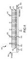
- FIG. 4is an example of a frequency-domain representation of a transmit signal 400 , in accordance with an example embodiment.
- Axis 402represents frequency
- axis 404represents signal power (e.g., in dB).
- An embodimentis implemented in a pilot symbol assisted modulation (PSAM) OFDM system with null edge sub-carriers. Embodiments may, alternatively, be implemented in other types of systems, although such other systems are not discussed in detail herein.
- PSAMpilot symbol assisted modulation
- the transmit signal 400includes a data component 408 and an SPS component 410 , which are modulated onto a plurality, N, of sub-carriers.
- the subcarriers occupied by the data component 408 , X k , of the transmit signal 400may be decomposed into several non-overlapping parts: 1) data-bearing subcarriers 412 , which may be denoted by a set of indices K d ; pilot subcarriers 414 , which may be denoted by a set of indices K p ; and null edge subcarriers 416 , which may be denoted by the set of indices K n .
- X k ⁇ K d0, so that the data component 408 of the transmit signal 400 only contains energy in data-bearing subcarriers 412 .
- Null edge subcarriers 416may be constrained, in an embodiment, to zero to limit the amount of spectral regrowth that may encroach on neighboring channels.
- Pilot signals 420may be defined as part of the SPS (e.g., SPS 332 , FIG. 3 and SPS 538 , FIG. 5 ).
- the subcarriers occupied by the SPS component 410 of the transmit signal 400may be decomposed into the same non-overlapping parts as the data component 408 , or more particularly: 1) synchronization subcarriers 412 , K d ; pilot subcarriers 414 , K p ; and null edge subcarriers 416 , K n .
- SPS component 410includes synchronization sequence information 422 conveyed within synchronization subcarriers 412 (e.g., data-bearing subcarriers 412 ), and a plurality of pilot signals 420 conveyed within pilot subcarriers 414 , in an embodiment. Because at least some of the synchronization subcarriers 412 occupied by the SPS component 410 are the same as the data-bearing subcarriers 412 occupied by the data component 408 , the synchronization sequence information 422 (and thus the SPS component 410 ) may be considered to be “embedded” within the data component 408 . Embodiments of methods for generating SPS components 410 will be described in more detail later in conjunction with FIG. 6 .
- Pilot signals 420(or pilot subcarriers 414 ) have constant power and are evenly spaced (e.g., a same number of data-bearing subcarriers 414 exist between consecutive pilot subcarriers 414 ), in an embodiment. In alternate embodiments, the positioning and spacing of pilot signals 420 may be different from that illustrated in FIG. 4 . In a particular embodiment, the pilot subcarrier 414 spacing is less than the number of null edge subcarriers (e.g., N/
- MSEmean square error
- the amount of power in pilot subcarriers 414may be quantified according to the equation:
- Equation ⁇ ⁇ 6which is the ratio of pilot power to the total SPS power.
- the value of the embedding factor, ⁇dictates how much relative signal power is allocated to the data component 408 , X k , of the transmit signal 400 as opposed to the SPS component 410 , S k , of the transmit signal 400 .
- the embedding factor, ⁇has a fixed value, and accordingly the first scaling factor 322 and the second scaling factor 330 also have fixed values.
- the transmitter 300may adjust the value of the embedding factor dynamically.
- the embedding factoris increased, the relative power of the SPS component 410 with respect to the data component 408 also will increase. This may be desirable, for example, when the channel is relatively harsh, and increased PAR reductions are desired.
- a tradeoff to increasing the embedding factor (and thus increasing PAR reductions)may be that, as a harsh channel improves (e.g., becomes less harsh), the receiver may have more than enough channel SNR to demodulate, although the received signal SNR may be limited by the distortion induced by the power amplifier 316 .
- the receivermay feed back information back to the transmitter 300 , which indicates the receiver demodulation performance, and thus that the transmitter 300 may increase D and/or ⁇ .
- Such increasesmay enable transmitter 300 further to reduce PAR and to minimize the probability of distortion to the transmitted signal that may be induced by the non-linear power amplifier 316 .
- the relative power of the SPS component 410 with respect to the data-bearing component 408also will decrease.
- Decreasing the embedding factormay be desirable, for example, when the power amplifier 316 is not inducing significant distortion onto the transmitted signal, and when the demodulation performance of the receiver (e.g., as indicated through feedback from the receiver) is not significantly limited by power amplifier induced distortions and/or by channel multi-path induced distortion, provided that sufficient synchronization performance may still be achieved.
- decreasing the embedding factormay result in smaller PAR reductions.
- the value of the embedding factormay be set to 0, and/or data/scaling factor combiner 302 and SPS/scaling factor combiners 306 may be disabled. In that case, transmit signal 400 will include only a data component 408 , as the power of any SPS component 410 effectively will have been reduced to zero.
- a preamble(not illustrated) may be transmitted along with the data in order to facilitate synchronization with the signal at the receiver.
- FIG. 5is a simplified block diagram of a receiver 500 , in accordance with an example embodiment.
- Receiver 500includes an antenna 502 , a down-converter 504 , a plurality of correlators 506 , a peak detector 508 , offset estimator/corrector 509 , a channel estimator/corrector 516 , an SPS removal element 518 , scaling element 520 , and a phase shift element 522 operatively coupled together as illustrated in FIG. 5 , in an embodiment.
- receiver 500includes a conjugate correlation receiver, which is adapted to perform a blind phase sequence detection method, in which the receiver 500 may exclude the traditional processes of performing time or frequency synchronization, and in which the receiver 500 may not have a priori knowledge of the channel characteristics.
- Antenna 502is adapted to receive a wireless RF signal 530 from the channel, and to produce an analog RF signal 532 .
- the wireless RF signal 530represents a channel-affected version of a selected signal that includes a data signal combined with an SPS.
- Down-converter 532is adapted to perform an analog-to-digital conversion and a frequency down-conversion process on the analog RF signal 532 , in order to produce an IF or baseband received signal 534 .
- the received signal 534represents a channel-affected version of a selected signal (e.g., selected signal 346 , FIG. 3 ) that was transmitted by a transmitter (e.g., transmitter 300 , FIG.
- transmitter 500is adapted to determine estimated channel perturbations (e.g., multi-path fading, TO, CFO, and/or other signal perturbations) reflected within the received signal 534 , to apply corrections to the received signal 534 based on the estimated channel perturbations, and to produce an output data symbol 580 based on the corrected received signal, where the output data symbol 580 represents an estimate of the input data symbol (e.g., input data symbol 320 , FIG. 3 ) that was processed and transmitted by the transmitter.
- estimated channel perturbationse.g., multi-path fading, TO, CFO, and/or other signal perturbations
- estimated channel perturbationsare determined by the plurality of correlators 506 , the peak detector 508 , the offset estimator/corrector 509 , and the channel estimator/corrector 516 .
- the plurality of correlators 506includes computational apparatus adapted to receive the received signal 534 , to obtain a plurality of candidate synchronization sequences 538 , and to produce a plurality of conjugate correlation (CC) outputs 536 , r (d) [u]. More particularly, each correlator 506 is adapted to correlate the received signal 534 with a different candidate synchronization sequence 538 , s (d) [n].
- the candidate synchronization sequences 538include time-domain versions of the same synchronization/pilot sequences (e.g., SPS 332 , FIG. 3 ) as were combined by the transmitter (e.g., transmitter 300 , FIG. 3 ) with the phase shifted input data (e.g., phase shifted input data 328 , FIG. 3 ).
- the transmittere.g., transmitter 300
- the receiver 500each may have knowledge of the candidate SPS by each having access to substantively identical tables of SPS, although the transmitter's SPS table may include SPS represented in the frequency domain, and the receiver's SPS table may include the same SPS represented in the time domain, in an embodiment.
- the number of conjugate correlation outputs 536 producedequals the candidate number quantity D, although the number of conjugate correlation outputs 536 may be different, in other embodiments.
- the received signal 534may be divided into a plurality of subcode sequences in order to reduce the number of operations associated with performing the correlation process.
- each conjugate correlation output 536may be produced, by generating a sub-correlation for each subcode sequence, and summing together the sub-correlations to form a summed result having a single correlation peak.
- Correlators 506provide the plurality of conjugate correlation outputs 536 to peak detector 508 .
- correlators 506may not provide (or peak detector 508 may not evaluate) those of the plurality of conjugate correlation outputs 536 that have correlation peaks below a threshold.
- Peak detector 508includes computational apparatus adapted to determine an estimate of the SLM index 540 , ⁇ tilde over ( ⁇ circumflex over (d) ⁇ , based on the conjugate correlation outputs 536 .
- the SLM index estimate 540is determined according to the equation:
- the SLM index estimate 540corresponds to the conjugate correlation output 536 that represents a highest correlation peak.
- embodimentsinclude blind phase sequence detection criterion (e.g., no side information representing the SLM index is transmitted) in order to determine the SLM index estimate 540 , and the SLM index estimate 540 is determined based on the conjugate correlations between the received signal 534 and the candidate synchronization sequences 538 .
- Correct detection of ⁇ tilde over (d) ⁇may depend on the magnitude of the peaks of
- the candidate SPS 538are designed so that the spurious correlation peaks are low.
- the candidate SPS 538are designed so that: ⁇ max CC ⁇ s (d) [n],s (d) [n ⁇ u] ⁇ th self , (Equation 12) where th self is a threshold that provides adequate system performance.
- Peak detector 508provides the SLM index estimate 540 , ⁇ tilde over ( ⁇ circumflex over (d) ⁇ , to offset estimator/corrector 509 (or more particularly to coarse offset estimator 510 ), along with the ⁇ tilde over ( ⁇ circumflex over (d) ⁇ th conjugate correlation output 541 (although this may be obtained from elsewhere, as well).
- Offset estimator/corrector 509includes a coarse offset estimator 510 , an offset corrector 512 , a time domain-to-frequency domain (TD-to-FD) transformer 514 , a fine offset estimator 515 , and a frequency domain-to-time domain (FD-to-TD) transformer 517 , in an embodiment.
- Coarse offset estimator 510includes computational apparatus adapted to determine a plurality of channel perturbations, including coarse timing offset (TO) estimates 542 and coarse carrier frequency offset (CFO) estimates 544 .
- TOcoarse timing offset
- CFOcoarse carrier frequency offset
- coarse offset estimator 510is adapted to determine a coarse timing offset estimate 542 , ⁇ circumflex over (n) ⁇ 0 , according to the equation:
- coarse offset estimator 510also is adapted to determine a coarse estimate of the carrier frequency offset (CFO) 544 , ⁇ circumflex over ( ⁇ ) ⁇ , according to the equation:
- the coarse CFO estimateis determined as the phase of the conjugate correlation output 536 that was determined by peak detector 508 to have the highest correlation peak.
- the coarse offset and estimator 510provides the estimated channel perturbations (e.g., coarse timing offset estimates 542 and coarse CFO estimates 544 ) to offset corrector 512 .
- Offset corrector 512includes computational apparatus adapted to receive the received signal 534 and the estimated channel perturbations, and to effectively compensate for those estimated channel perturbations in the received signal 534 by aligning the received signal 534 on a symbol boundary using the coarse timing offset estimate 542 and the coarse CFO estimate 544 , which may include removing the cyclic extension from the received signal 534 .
- offset corrector 512produces a coarsely-corrected signal 550 .
- the coarsely-corrected signal 550may be transformed to the frequency domain by time domain-to-frequency domain (TD-to-FD) transformer 514 , which includes computational apparatus adapted to perform a time domain-to-frequency domain transformation on the corrected signal 550 , in order to produce a frequency-domain, coarsely-corrected signal 553 .
- the time domain-to-frequency domain transformationmay include a Fourier transform (FT) or, more particularly, a fast Fourier transform (FFT), in various embodiments, although other types of time domain-to-frequency domain transformations may be performed in other embodiments.
- FTFourier transform
- FFTfast Fourier transform
- fine offset estimationmay then be performed using fine offset estimator 515 .
- fine offset estimator 515determines a fine CFO estimate, which is applied to the coarsely-corrected signal 550 by offset corrector 512 .
- fine offset estimator 515determines a fine CFO estimate, ⁇ circumflex over ( ⁇ ) ⁇ , using the pilot signals (e.g., pilot signals 420 , FIG. 4 ) within the frequency-domain, coarsely-corrected signal 553 . In an embodiment, this includes estimating the phase of each pilot signal (e.g., pilot signals 420 ), and determining the phase change in any particular pilot signal from OFDM symbol to OFDM symbol.
- the fine CFO estimatemay be determined using the common sub-carrier phase difference between OFDM symbols, which may then be averaged across all pilot sub-carriers to minimize estimation variance.
- the phases ⁇ ki1 and ⁇ ki2may be computed as ⁇ Y k1 p and ⁇ Y k2 p (where ⁇ represents the angle), respectively.
- the fine CFO estimatemay be determined according to the equation:
- Fine offset estimator 515may provide the fine CFO estimate to offset corrector 512 via a feedback path (not illustrated).
- fine offset estimator 515provides a feedback version 545 of the frequency-domain, coarsely-corrected signal to offset corrector 512 via frequency domain-to-time domain (FD-to-TD) transformer 517 , which transforms the feedback version 545 of the coarsely-corrected signal into the time domain to produce a time-domain, fed back, coarsely-corrected signal 547 .
- FD-to-TDfrequency domain-to-time domain
- the coarsely-corrected signal 550is retained in memory, and is not fed back to offset corrector 512 .
- offset corrector 512applies the fine CFO estimate to the coarsely-corrected signal (either signal 550 or 547 ) to re-produce the finely-corrected signal 551 .
- fine CFO correctionmay be performed in the frequency domain after fine offset estimator 515 , rather than performing the fine CFO correction in the time domain by offset corrector 512 .
- fine offset estimator 515also may determine a fine timing offset estimate and/or a carrier phase offset estimate. For example, fine offset estimator 515 may determine a fine timing offset estimate based on the phase slope between pilot sub-carriers common to each OFDM symbol, which also can be averaged over all symbols. Fine offset estimator 515 may determine a carrier phase offset estimate from the mean value of the phase slope in each OFDM symbol, in an embodiment.
- fine offset estimator 515When a fine timing and/or carrier phase offset are estimated, fine offset estimator 515 provides the fine timing and/or carrier phase offsets to channel estimator/corrector 516 , in an embodiment, for correction of the fine timing and/or carrier phase offset in the frequency domain. In an alternate embodiment, fine offset estimator 515 may provide the fine timing and/or carrier phase offsets, if estimated, to offset corrector 512 for correction in the time domain.
- the finely-corrected signal 551is transformed to the frequency domain by TD-to-FD transformer 514 , and the resulting corrected signal 552 is provided to channel estimator/corrector 516 .
- Channel estimator/corrector 516receives the corrected signal 552 , determines a channel estimate, and based on the channel estimate, proceeds to equalize the channel effects in the corrected signal 552 to produce an equalized combined signal 554 .
- Channel estimator/corrector 516is adapted to determine a channel estimate, ⁇ k based on the corrected signal 552 .
- the power amplifiere.g., power amplifier 316 , FIG.
- channel estimator/corrector 516may estimate the channel in the pilot subcarriers (e.g., pilot subcarriers 414 , FIG. 4 ) according to the equation:
- channel estimator/corrector 516may interpolate the pilot subcarrier channel estimates to the data-bearing subcarriers (e.g., data-bearing subcarriers 412 , FIG. 4 ), k ⁇ K d so that ⁇ k is defined for k ⁇ K d ⁇ K p .
- the symbol estimate MSEmay be determined according to the equation:
- Equation ⁇ ⁇ 19the MSE is dependent on the ratio of pilot to data subcarriers
- Channel estimator/corrector 516may then generate an equalized combined signal 554 by equalizing the channel effects based on the channel estimate.
- SPS removal element 518includes computational apparatus adapted to receive the equalized combined signal 554 , and to remove the scaled SPS 562 corresponding to the SLM index estimate 540 from the equalized combined signal 554 (e.g., to combine ⁇ square root over ( ⁇ ) ⁇ s k ( ⁇ tilde over ( ⁇ circumflex over (d) ⁇ ) with the equalized combined signal 554 ) in order to produce an estimated, phase shifted data signal 564 .
- the scaled SPS 562may be obtained by retrieving the SPS s k ( ⁇ tilde over ( ⁇ circumflex over (d) ⁇ ) corresponding to the SLM index estimate 540 from a table of SPS, which is accessible to or stored in receiver 500 , and by applying the scaling factor ⁇ square root over ( ⁇ ) ⁇ to the retrieved SPS.
- the SPS tableincludes one or more pre-generated sets of SPS, where each SPS in a set may be referenced by an SLM index.
- Each SPS in the receiver's SPS tableis represented in the frequency domain, in an embodiment. Embodiments of methods for generating sets of SPS will be described in more detail later in conjunction with FIG. 6 .
- Scaling element 520is adapted to apply a scaling factor to the estimated, phase shifted data signal 564 , in order to produce a scaled, phase shifted data signal 566 , which has a peak amplitude approximately equal to that of the original input data, X[n].
- Phase shift element 522includes computational apparatus adapted to phase shift the scaled, phase shifted data signal 566 by a phase shift value 568 corresponding to the SLM index estimate 540 (e.g., to shift the scaled, phase shifted data signal 566 by
- the remaining signalis demodulated in order to produce the output data symbol 580 , ⁇ circumflex over (X) ⁇ k [n].
- the SLM index estimate 540represents a correctly-detected SLM index (e.g., an SLM index corresponding to the selected signal 346 , FIG. 3 , identified at the transmitter 300 )
- blind phase sequence detectionhas been robustly performed by receiver 500
- the output data symbol 580reflects an accurate estimate of the input data symbol (e.g., input data symbol 320 , FIG. 3 ).
- both a transmittere.g., transmitter 300 , FIG. 3
- a receivere.g., receiver 500 , FIG. 5
- Embodimentsinclude methods for generating sets of SPS that result in significant PAR reductions and that have comparable synchronization and channel estimation properties, when compared with traditional methods.
- the magnitude of PAR reductiondepends on the value of the embedding factor, ⁇ , where larger PAR reductions may be achieved when ⁇ has a relatively large value (e.g., when ⁇ >0.6), and smaller PAR reductions may be achieved when ⁇ has a relatively small value (e.g., when ⁇ 0.6).
- a value for ⁇may derived assuming perfect acquisition by minimizing the maximum symbol estimate in E ⁇
- 2 ⁇ , or MSE x , where MSE xE[
- an SPSmay be generated to have a PAR ⁇ 0.5 dB, although embodiments may be implemented in which an SPS has a PAR ⁇ 0.5 dB, as well.
- SPS generated according to an embodimentmay have excellent synchronization properties.
- synchronizationincludes estimating the SLM index, ⁇ tilde over (d) ⁇ , for the transmitted signal, estimating a coarse timing offset, n 0 , and estimating a coarse CFO, ⁇ circumflex over ( ⁇ ) ⁇ .
- An estimation of which phase sequence index, ⁇ tilde over (d) ⁇ , was transmittedmay be made via criterion specified in Equation 11, above. From Equation 11, it is apparent that correct estimation of ⁇ tilde over (d) ⁇ depends on the peaks of
- sets of SPSare generated so that spurious correlation peaks are low, when compared with the peak in
- a set of SPSis generated so that max u,d ⁇ q CC ⁇ s d [n],s q [n ⁇ u] ⁇ is minimized using an optimization procedure.
- a set of SPSmay be generated more simply according to the following equation:
- th crossis a threshold that is determined to provide adequate system performance by considering an optimal or near-optimal balance between the synchronization detection performance (e.g., a probability of missing a synchronization signal and a probability of falsely detecting a synchronization signal when none is present), the estimation quality (e.g., mean square error (MSE) or other quality estimation quantities) of the timing, frequency, and phase estimation performance for synchronization, the channel estimation performance (e.g., MSE or other channel estimation quantities), and the receiver demodulator bit error rate (BER) performance.
- MSEmean square error
- BERreceiver demodulator bit error rate
- a coarse timing offset estimate(e.g., coarse timing offset estimate 542 ), ⁇ circumflex over (n) ⁇ 0 , may be determined according to Equation 13, above. As Equation 13 indicates, the coarse timing offset estimate is determined based on the maximum of the ⁇ tilde over ( ⁇ circumflex over (d) ⁇ th conjugate correlation output.
- the channel estimatore.g., channel estimator/corrector 516 , FIG.
- the SPSmay compensate for differences
- a set of SPSis generated so that max d,u ⁇ n 0 CC ⁇ s (d) [n],s (d) [n ⁇ u] ⁇ is minimized.
- a set of SPSmay be generated more simply according to the equation:
- th selfis a predetermined threshold (e.g., a threshold that is determined to provide adequate system performance).
- th self⁇ 0.1, although th self may be equal to or less than 0.1, in other embodiments.
- FIG. 6is a flowchart of a method for generating a set of SPS, according to an example embodiment.
- the set of SPSmay be used, for example, as a set of pre-generated SPS that are accessed by a transmitter (e.g., transmitter 300 , FIG. 3 ) and a receiver (e.g., receiver 500 , FIG. 5 ), as discussed previously in conjunction with FIGS. 3 and 5 .
- a transmittere.g., transmitter 300 , FIG. 3
- a receivere.g., receiver 500 , FIG. 5
- the number of SPS in a set, Dis an integer having a value between 2 and 10, although a set of SPS may have more SPS, in other embodiments.
- each SPS in the setis generated by performing multiple iterations of a time-frequency projection (e.g., a Projection onto Convex Sets (POCS) algorithm), or an iterative convergence process based on PAR results and/or mean square error properties.
- a time-frequency projectione.g., a Projection onto Convex Sets (POCS) algorithm
- the number of iterations, Iis an integer having a value between about 100 and 300, although a smaller or larger number of iterations may be performed, in alternate embodiments.
- the flowchart of FIG. 6includes an inner loop, which represents an iteration of a time-frequency projection (e.g., the inner loop is performed I times) in order to generate a single SPS, and an outer loop, which is performed S times in order to generate a set of S candidate SPS. Further steps of the method reduce the number of candidate SPS to a set of D SPS (e.g., D ⁇ S), as will be explained in detail below.
- the methodmay begin, in block 602 , by initializing an inner loop counter, i, and an outer loop counter, s.
- Inner loop counter, iindicates a current time-frequency projection iteration being performed for the SPS being generated, and accordingly may be referred to as an iteration counter.
- the inner loop counteris initialized to a value of 1 and is incremented by 1 for each iteration being performed up to a value of I, although the inner loop counter may be initialized to some other value, and/or may be incremented differently, or may be a decrementing counter, in alternate embodiments.
- Outer loop counter, sindicates which candidate SPS in a set is being generated, and accordingly may be referred to as an SPS number counter.
- the outer loop counteris initialized to a value of 1 and is incremented by 1 for each candidate SPS being generated up to a value of S, although the outer loop counter may be initialized to some other value, and/or may be incremented differently, or may be a decrementing counter, in alternate embodiments.
- the group of blocks 603are executed in order to generate a single candidate SPS.
- generation of a candidate SPSincludes using an iterative time-frequency projection algorithm (e.g., a POCS algorithm).
- the algorithmis initialized using different initial conditions (e.g., a different random phase) from the other candidate SPS that are generated.
- generation of a candidate SPSmay begin, in block 604 , by initializing the algorithm by generating an initial, random phase, constant modulus phase sequence, to which a pre-determined power profile is applied.
- the random phaseis determined by choosing a uniformly generated random phase between 0 and 2 ⁇ radians or between ⁇ and ⁇ radians.
- the actual generation of the phasemay be performed using a uniform random number generator between 0 and 1 inclusive (e.g., denoting as r u ), and applying the randomly generated number to a complex phasor of form exp(j2 ⁇ r u ).
- the power profile that is applied to the phase sequenceis determined by computing a desired amplitude for each subcarrier, where the amplitudes for the subcarriers are computed to provide a lowest symbol MSE performance at the receiver, in an embodiment.
- the power profileis applied by multiplying the desired amplitudes by the subcarrier value generated in the inner loop of FIG. 6 (e.g., in block 604 ), in order to produce a power-adjusted phase sequence.
- the applied power profileis the same for all SPS generated in the set.
- the length of the frequency-domain sequenceis in a range of 32 to 124 values, in an embodiment, although shorter or longer sequences may be generated, in alternate embodiments.
- a time-domain transformationis performed on the initial, power-adjusted phase sequence to produce a time-domain sequence.
- the time domain-to-frequency domain transformationmay include a Fourier transform or, more particularly, a discrete Fourier transform (DFT), in various embodiments, although other types of time domain-to-frequency domain transformations may be performed in other embodiments.
- DFTdiscrete Fourier transform
- amplitudes of the time-domain sequenceare set to unity while maintaining phases of the time-domain sequence to produce an amplitude-adjusted time-domain sequence. More particularly, given that the time domain version may not be unity in amplitude, the sequence is converted to magnitude and phase (i.e., polar form). The magnitude of the converted sequence is set so that the amplitude is unity, while the original phase is retained. The converted sequence is then converted back to real and imaginary (i.e., rectangular form) to produce the amplitude-adjusted time-domain sequence.
- a frequency-domain transformationis performed on the amplitude-adjusted time-domain sequence to produce an adjusted frequency-domain sequence.
- the frequency domain-to-time domain transformationmay include an inverse Fourier transform or, more particularly, an inverse discrete Fourier transform, in various embodiments, although other types of frequency domain-to-time domain transformations may be performed in other embodiments.
- the power profileis applied to the adjusted frequency-domain sequence while maintaining phases of the adjusted frequency-domain sequence in order to produce an adjusted candidate sequence.
- a determination is made whether the last iteration has been performed for the candidate SPS being generated (e.g., whether iI). If not, then the inner loop counter is incremented (e.g., by 1), in block 616 , and the method iterates as shown by repeating blocks 606 - 614 at least an additional time using the adjusted candidate sequence.
- the then-current adjusted candidate sequencerepresents a completed version of a candidate SPS.
- a subset of D candidate SPSmay be selected, via blocks 622 , 624 , 626 , and 628 , which will represent the set of SPS being generated according to the method of FIG. 6 .
- certain candidate SPS that were generated via blocks 604 - 620may be eliminated from the set of candidate SPS.
- candidate SPSare eliminated that do not meet a PAR selection criteria (e.g., a selection criteria based on PAR).
- the PAR selection criteriamay be a PAR threshold, th PAR , and those candidate SPS having a PAR value that is greater than (or is equal to or greater than) the PAR threshold may be eliminated from the set of candidate SPS.
- a PAR thresholdmay have a value in a range between about 0 dB and about 2.0 dB, in an embodiment, although the PAR threshold may be smaller or greater than the values within the above-given range, in other embodiments.
- an inclusion process(rather than an exclusion process) may be performed, in which those candidate SPS having a PAR value that is less than a PAR threshold may be allowed to remain within the set of candidate SPS.
- block 622may be excluded altogether from the SPS set generation method.
- a plurality of correlationsare performed among the candidate SPS (e.g., the candidate SPS that remain after block 622 ) to generate a plurality of correlation values.
- performing the correlationsincludes performing a plurality of cross-correlations among the candidate SPS to generate a plurality of cross-correlation results, and also performing a plurality of auto-correlations among the candidate SPS to generate a plurality of auto-correlation results.
- P 2 cross-correlationsare performed, where P is a number of candidate SPS being correlated.
- each candidate SPSis correlated with each other candidate SPS in order to generate P 2 cross-correlation results.
- Each cross-correlation resultrepresents a maximum peak for the cross-correlation, and may be represented by
- P auto-correlationsare performed (e.g., an auto-correlation for each of the P candidate SPS being correlated), and the secondary maximum peak from each auto-correlation is determined as an auto-correlation result. Accordingly, P auto-correlation results are determined.
- An auto-correlation result corresponding to the secondary maximum peakmay be represented by max
- a desired correlation outputtypically produces a notable peak, where any secondary peak is very low in comparison.
- this correlation propertyis exploited for the purpose of detecting whether a signal is present.
- information at the correlation peak(s)is used to determine parameters such as timing offset and frequency offset, for example.
- the max cross-correlation resultsare used to determine at what probability a sequence other than the desired sequence may be chosen, where an inaccurate choice may result in synchronization detection errors and subsequent phase sequence detection errors.
- the maximum auto-correlation performance resultsare used to determine at what probability an incorrect peak of the correlation output may be chosen, where an inaccurate choice may result in estimation errors in timing and frequency offset, for example.
- each permutationincludes a different combination of D SPS selected from the set of candidate SPS. Permutations may be determined for each possible combination of SPS, although in other embodiments, a smaller number of permutations may be determined.
- a permutationis identified, from the plurality of permutations, as a selected set of SPS (e.g., the end result of the SPS set generation method).
- the identified permutationcorresponds to the permutation having a smallest maximum max-correlation value (e.g., the set that gives the smallest maximum cross-correlations within the set and/or the smallest secondary peak in the auto-correlations in the set).
- identifying the selected permutation from the plurality of permutationsincludes identifying a permutation that corresponds to a maximum cross correlation threshold and/or a maximum secondary peak of the auto-correlations.
- a low secondary peakindicates a more definitive result for each auto-correlation, and the same is true for a maximum cross-correlation (e.g., one would desire the maximum peak of the cross-correlation to be as small as possible). After identifying the permutation, the method may then end.
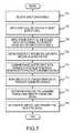
- FIG. 7is a flowchart of a method for generating and transmitting wireless signals that include embedded SPS, in accordance with an example embodiment. Embodiments of the method are only briefly discussed in conjunction with FIG. 7 , as various details and alternate embodiments were discussed in more detail above.
- the methodmay begin, in block 702 , when a transmitter (e.g., transmitter 300 ) receives (e.g., by data/scaling factor combiner 302 ) an input data symbol (e.g., input data symbol 320 ).
- a first scaling factore.g., first scaling factor 322
- the first scaling factormay have a value of ⁇ square root over (1 ⁇ ) ⁇ , where ⁇ is an embedding factor having an absolute value between 0 and 1. In other embodiments, the first scaling factor may have a different value.
- phase shifts 326are applied (e.g., by phase shifters 304 ) to the scaled input data symbol, in order to produce a plurality of phase shifted input data signals (e.g., phase shifted input data signals 328 ).
- a plurality of SPS(e.g., SPS 332 ) are obtained (e.g., a plurality of SPS generated according to an embodiment), and a second scaling factor (e.g., second scaling factor 330 ) is applied to the plurality of SPS in order to produce a plurality of scaled SPS (e.g., scaled SPS 334 ).
- the second scaling factormay have a value of ⁇ square root over ( ⁇ ) ⁇ , in an embodiment, although the second scaling factor may have a different value, in other embodiments.
- the second scaling factorhas an inverse mathematical relationship with the first scaling factor (e.g., by varying the value of the embedding factor, as the second scaling factor value increases, the first scaling factor value decreases, and vice versa).
- each one of the plurality of phase shifted input data signalsis combined (e.g., by data/SPS combiners 308 ) with one of the scaled SPS in order to produce a plurality of combined signals (e.g., combined signals 340 ).
- a frequency domain-to-time domain transformationis performed (e.g., by FD-to-TD transformers 310 ) on each of the combined signals, in order to produce a plurality of candidate signals (e.g., candidate signals 342 ).
- peak-to-average ratiosare determined (e.g., by signal selector 312 ) for some or all of the candidate signals, and based on the peak-to-average ratios, a selected signal (e.g., selected signal 346 ) is identified from the candidate signals. As discussed previously, the selected signal may be identified as the candidate signal with the lowest PAR, in an embodiment.
- the selected signalis up-converted (e.g., by up-converter 314 ), amplified (e.g., by power amplifier 316 ), and transmitted over the channel (e.g., channel 106 , FIG. 1 ).
- FIG. 8is a flowchart of a method for receiving and processing wireless signals that include embedded SPS, in accordance with an example embodiment. Embodiments of the method are only briefly discussed in conjunction with FIG. 8 , as various details and alternate embodiments were discussed in more detail above.
- the methodmay begin, in block 802 , when a receiver (e.g., receiver 500 ) receives (e.g., via antenna 502 ) a wireless RF signal (e.g., RF signal 530 ) from the channel.
- the received RF signalincludes a channel-affected version of a data signal combined with an SPS, as discussed in conjunction with the description of embodiments of the transmitter (e.g., transmitter 300 , FIG. 3 ), and embodiments of the method for generating and transmitting the wireless RF signal (e.g., FIG. 7 ).
- the received RF signalis down-converted and digitized (e.g., by down-converter 532 ), in order to produce an IF or baseband received signal (e.g., received signal 534 ).
- the received signalis correlated (e.g., by correlators 506 ) with a plurality of SPS (e.g., SPS 538 generated according to an embodiment) to produce a plurality of conjugate correlation outputs (e.g., conjugate correlation outputs 536 ).
- SPSe.g., SPS 538 generated according to an embodiment
- conjugate correlation outputse.g., conjugate correlation outputs 536
- an SLM index estimatee.g., SLM index estimate 540
- peak detector 508e.g., a peak detector 508
- coarse offset estimates(e.g., coarse TO and coarse CFO) may be determined (e.g., by coarse offset estimator 510 ) based on the conjugate correlation output corresponding to the SLM index estimate.
- correctionsare made (e.g., by offset corrector 512 ) for the coarse timing and carrier frequency offsets in the received signal, in order to produce a coarsely-corrected signal (e.g., coarsely-corrected signal 550 ).
- fine estimated offsetsmay be determined (e.g., by fine offset estimator 515 ) based on the coarsely-corrected signal, and in block 816 , additional corrections may be made (e.g., by offset corrector 512 in the time domain or by a frequency-domain offset corrector), in order to produce a finely-corrected signal (e.g., finely-corrected signal 551 ).
- channel effectsare estimated (e.g., by channel estimator/corrector 516 ) from a frequency-domain version of the finely-corrected signal.
- the finely-corrected signalis then equalized based on the estimated channel effects, in order to produce an equalized combined signal (e.g., equalized combined signal 554 ).
- a scaled SPS(e.g., scaled SPS 562 ) corresponding to the SLM index estimate is removed (e.g., by SPS removal element 518 ) from the equalized combined signal, in order to produce an estimated, phase shifted data signal (e.g., estimated, phase shifted data signal 564 ), which may be scaled (e.g., by scaling element 520 ).
- a phase shift operationis performed (e.g., by phase shift element 522 ), in block 822 , which includes phase shifting the scaled, phase shifted data signal by a phase shift value corresponding to the SLM index estimate. This operation results in the production of an output data symbol (e.g., output data symbol 580 ), which reflects and estimate of the input data symbol (e.g., input data symbol 320 , FIG. 3 ). The method may then end.
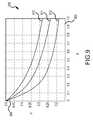
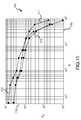
- FIGS. 9-15indicate potential simulated results for systems that employ various example embodiments.
- FIG. 9is a chart 900 plotting relationships between an embedding factor representing a ratio, ⁇ , of synchronization/pilot sequence power to signal power, and a ratio, ⁇ , of pilot power to the total synchronization/pilot sequence power for various ratios of pilot to data subcarriers, or
- Chart 900includes a ⁇ axis 902 and a ⁇ axis 904 .
- the MSEis dependent on the ratio of pilot to data subcarriers. Accordingly, adjusting the ratio of pilot to data subcarriers affects the MSE.
- Plot 910represents simulated results when the relationship between ⁇ and ⁇ is
- 0.15.
- Plot 911represents simulated results when the relationship between ⁇ and ⁇ is
- 0.10.
- plot 912represents simulated results when the relationship between ⁇ and ⁇ is
- 0.05.
- FIG. 10is a chart 1000 plotting bit error rate (BER) performance that may be achieved using two example SPS-SLM embodiments.
- Chart 1000includes a signal-to-noise ratio (SNR) axis 1002 and a BER axis 1004 .
- SNRsignal-to-noise ratio
- the SPS used to generate plot 1000were generated using a convex optimization algorithm, according to an embodiment.
- an ideal soft limiter channelwas used with an input backoff of 3 dB.
- the multi-path channelwas set to length 16 with an exponential delay spread such that
- a ⁇ ⁇ ⁇0 14 ⁇ e - ⁇ .
- N256, with
- 16,
- 240, and
- 0.
- a comparison between plots 1010 and 1012indicates that significantly improved BER performance may be achieved when PAR reduction is used, in accordance with an example embodiment.
- a further comparison between plots 1012 and 1014indicates that even further improved BER performance may be achieved when the candidate number quantity, D, is increased.
- a comparison between plots 1110 - 1112indicates that comparable acquisition performance may be achieved using SPS generated according to an embodiment when compared with traditional m-sequences.
- FIG. 12is a chart 1200 indicating channel estimation performance for a system using SPS generated according to an embodiment and a system that uses traditional binary sequences.
- Channel estimation performancewas measured as a plot of the embedding factor, ⁇ (measured along axis 1202 ) versus the mean square error (measured along axis 1204 ).
- Plot 1210corresponds to channel estimation performance for a signal in which channel estimation pilots and a pseudo-noise code derived from an m-sequence were embedded according to traditional techniques.
- Plot 1211corresponds to channel estimation performance for a signal in which an SPS generated according to an embodiment were embedded.
- a comparison between plots 1210 and 1211indicates that low power portions of the m-sequence, which are non-flat frequency response, results in higher mean square error, when compared with an SPS generated according to an embodiment, which has a relatively flat frequency response. Accordingly, the use of SPS generated according to an embodiment may result in significantly improved channel estimation performance.
- FIG. 13is a chart 1300 illustrating a complementary cumulative distribution function (CCDF) of the PAR for signals produced using two different embedding sequences and various embedding factors, ⁇ , in accordance with various example embodiments.
- a comparison between the two groups 1310 , 1312 of tracesindicates that, for a given embedding factor, significant PAR reductions may be achieved using constant modulus SPS, in accordance with various embodiments.
- FIG. 14is a plot 1400 of the convergence characteristics of the PAR for the five lowest-PAR SPS (out of 150 different initial conditions), which were generated according to an embodiment.
- FIG. 15is a scatter plot 1500 of the PAR and mean square error (MSE) after 600 iterations of the SPS generation methods discussed previously (e.g., blocks 604 - 616 , FIG. 6 ) for 150 different initial conditions.
- the parameters used to generate the scatter plot 1500were the same as for the plot 1400 illustrated in FIG. 14 .
- MSEcorresponds to the mean squared difference between ⁇ [k] and ⁇ square root over (P[k]) ⁇
- the PARis the PAR of ⁇ [n].
- the PAR and MSEare highly dependent on the initial conditions of the SPS generation algorithm.
- messagesmay be sent by system elements in sequences that are different from the sequences described above.
- words such as “connected” or “coupled to” used in describing a relationship between different elementsdo not imply that a direct physical connection must be made between these elements.
- two elementsmay be connected to each other physically, electronically, logically, or in any other manner, through one or more additional elements, without departing from the scope of the inventive subject matter.
- a general-purpose processormay be a microprocessor, but in the alternative, the processor may be any conventional processor, controller, microcontroller, or state machine.
- a processormay also be implemented as a combination of computing devices, such as a combination of a DSP and a microprocessor, a plurality of microprocessors, one or more microprocessors in conjunction with a DSP core, or any other such configuration.
- a software modulemay reside in random access memory, flash memory, read only memory (ROM), erasable programmable ROM (EPROM), electrical EPROM, registers, hard disk, a removable disk, a compact disc ROM (CD-ROM), or any other form of storage medium known in the art.
- An exemplary storage mediumis coupled to the processor such that the processor can read information from, and write information to, the storage medium.
- the storage mediummay be integral to the processor.
- the processor and the storage mediummay reside in an ASIC.
- the ASICmay reside in a user terminal.
- the processor and the storage mediummay reside as discrete components in a user terminal.
- An embodimentincludes a method for generating a set of synchronization/pilot sequences.
- the method embodimentincludes the steps of generating a candidate synchronization/pilot sequence using initial conditions, and repeating the generating step a first number of iterations using different initial conditions for each iteration to generate a plurality of candidate synchronization/pilot sequences.
- the method embodimentalso includes performing a plurality of correlations among the candidate synchronization/pilot sequences to generate a plurality of correlation values, determining a plurality of permutations of the candidate synchronization/pilot sequences, wherein each permutation of the plurality of permutations includes a different set of candidate synchronization/pilot sequences, and wherein each permutation includes a number, D, of candidate synchronization/pilot sequences, and identifying a selected permutation from the plurality of permutations, wherein the selected permutation corresponds to the set of synchronization/pilot sequences being generated.
- An embodiment of a method for generating a wireless signal in which a synchronization/pilot sequence is embeddedincludes the steps of combining each synchronization/pilot sequence of a set of synchronization/pilot sequences with phase shifted input data to produce a plurality of combined signals, determining peak-to-average power ratios for at least some of the combined signals, identifying a selected combined signal based on the peak-to-average power ratios, and transmitting the selected combined signal over a wireless communication channel.
- the set of synchronization/pilot sequencesincludes synchronization/pilot sequences generated by generating a plurality of candidate synchronization/pilot sequences, wherein each candidate synchronization/pilot sequence of the plurality is generated using a different random phase, performing a plurality of correlations among the candidate synchronization/pilot sequences to generate a plurality of correlation values, determining a plurality of permutations of the candidate synchronization/pilot sequences, wherein each permutation of the plurality of permutations includes a different set of candidate synchronization/pilot sequences, and wherein each permutation includes a number, D, of candidate synchronization/pilot sequences, and identifying a selected permutation from the plurality of permutations, wherein the selected permutation corresponds to the set of synchronization/pilot sequences being generated.
Landscapes
- Engineering & Computer Science (AREA)
- Signal Processing (AREA)
- Computer Networks & Wireless Communication (AREA)
- Mobile Radio Communication Systems (AREA)
- Digital Transmission Methods That Use Modulated Carrier Waves (AREA)
Abstract
Description
z[n]=(fPA(y[n−n0])*h[τ])e−j2πε/N+η[n], (Equation 1)
where fPA(·) represents the power amplifier input-to-output characteristic, which may be assumed to be time-invariant (although the input-to-output characteristic may be time-variant, in other embodiments), h[τ] represents
In a particular embodiment, the embedding factor has a value in a range of about 0.25 to about 0.35. In another embodiment, the embedding factor has a value in a range of about 0.2 to about 0.4. In still other embodiments, the embedding factor may have higher or lower values than the above-given ranges. The scaled
to the scaled
where D is a value referred to herein as a candidate number quantity, d is an index referred to herein as a relational index, and d∈ε{1, 2, . . . , D}. The candidate number quantity, D, may be selected as any integer number from 1 to 16, in an embodiment, although the candidate number quantity may be a larger number, in other embodiments. In a particular embodiment, the candidate number quantity is selected as an integer number between 3 and 10. In an embodiment, the number of phase shifted input data signals328 produced equals the candidate number quantity D, although the number of phase shifted input data signals328 may be different, in other embodiments. The different phase shifts326 may be represented within entries of a table of phase shift values, in an embodiment, and the relational index, d, may be used an index into the phase shift value table, among other things. Accordingly, the phase shift value table may have D entries, in an embodiment, although the phase shift value table may have more or fewer entries in other embodiments.
In an embodiment, the number of combined
where x(d)[n]=IDFT{Xkejφ
| TABLE 1 | ||||
| k ε Kd | k ε Kp | k ε Kn | ||
| Xk | ≠0 | =0 | =0 | ||
| Sk | ≠0 | ≠0 | =0 | ||
| Yk | ≠0 | ≠0 | =0 | ||
which is the ratio of pilot power to the total SPS power.
Yk=Xk√{square root over (1−ρ)}+Sk√{square root over (ρ)}, (Equation 7)
where Xkrepresents and
z({tilde over (d)})[n]=(fPA(y({tilde over (d)})[n−n0])*h[τ])e−j2πε/N+η[n], (Equation 8)
where fPA(·) represents the power amplifier input-to-output characteristic, which may be assumed to be time-invariant (although the input-to-output characteristic may be time-variant, in other embodiments), h[τ] represents a multi-path fading component of the channel, y({tilde over (d)})[n−n0] represents the transmitted signal, y({tilde over (d)})[n], subjected to a TO component, e−j2πε/Nrepresents a CFO component, η[n] represents an additive noise component, * is the convolution operator, and {tilde over (d)} is the SLM index. It is to be noted that any carrier phase shift present between the transmitter and receiver is assumed to be included in the phase of the channel at the receiver.
r(d)[u]=CC{s(d)[n],z({tilde over (d)})[n−u]}, (Equation 9)
where the conjugate correlation between two length-N sequences may be defined as:
where (·)* is the conjugate operation.
Accordingly, the
└maxCC{s(d)[n],s(d)[n−u]}┘<thself, (Equation 12)
where thselfis a threshold that provides adequate system performance.
Accordingly, the coarse timing offset
Essentially, the coarse CFO estimate is determined as the phase of the
Wk({tilde over (d)})=IDFT{z({tilde over (d)})[n+{circumflex over (n)}0]}ej2π{circumflex over (ε)}/N, (Equation 16)
which yields Wk({tilde over (d)})=Yk({tilde over (d)})Hk+ηk+δk+ιk, where δkis the distortion noise caused by the power amplifier (e.g.,
Wk({tilde over (d)})=Yk({tilde over (d)})Hk+ηk, (Equation 18)
where ηk≈CN(0,ση2). Using these assumptions and the first order approximation that E[|ηk|2|{circumflex over (X)}k|2Hk]≈σ2for k∈Kd, the symbol estimate MSE may be determined according to the equation:
As Equation 19 indicates, the MSE is dependent on the ratio of pilot to data subcarriers |Kp|/|Kd|. Also, the minimizing the pilot subcarrier power is achieved by setting β=1 when perfect synchronization is assumed. However, in an embodiment, β is selected such that β<1, in order to achieve desired synchronization performance.
z({tilde over (d)})[n]=((fPA(y({tilde over (d)})[n−n0])*h[τ])e−j2πε/N+η[n])ej2π{circumflex over (ε)}/N. (Equation 20)
The remaining signal is demodulated in order to produce the
where thcrossis a predetermined threshold. More particularly, in an embodiment, thcrossis a threshold that is determined to provide adequate system performance by considering an optimal or near-optimal balance between the synchronization detection performance (e.g., a probability of missing a synchronization signal and a probability of falsely detecting a synchronization signal when none is present), the estimation quality (e.g., mean square error (MSE) or other quality estimation quantities) of the timing, frequency, and phase estimation performance for synchronization, the channel estimation performance (e.g., MSE or other channel estimation quantities), and the receiver demodulator bit error rate (BER) performance. In an embodiment, thcross<0.1, although thcrossmay be equal to or less than 0.1, in other embodiments.
where thselfis a predetermined threshold (e.g., a threshold that is determined to provide adequate system performance). In an embodiment, thself<0.1, although thselfmay be equal to or less than 0.1, in other embodiments.
In addition, in an embodiment P auto-correlations are performed (e.g., an auto-correlation for each of the P candidate SPS being correlated), and the secondary maximum peak from each auto-correlation is determined as an auto-correlation result. Accordingly, P auto-correlation results are determined. An auto-correlation result corresponding to the secondary maximum peak may be represented by max|s(s)[n]

Also, N=256, with |Kp|=16, |Kd|=240, and |Kn|=0. The pilot tones were evenly spaced with equal power, and the embedding factors were chosen to be β=0.25 and ρ=0.35.
Claims (20)
Priority Applications (2)
| Application Number | Priority Date | Filing Date | Title |
|---|---|---|---|
| US12/051,535US8358644B2 (en) | 2007-04-13 | 2008-03-19 | Methods and apparatus for generating synchronization/pilot sequences for embedding in wireless signals |
| US12/725,985US8379752B2 (en) | 2008-03-19 | 2010-03-17 | Methods and apparatus for multiple-antenna communication of wireless signals with embedded synchronization/pilot sequences |
Applications Claiming Priority (2)
| Application Number | Priority Date | Filing Date | Title |
|---|---|---|---|
| US91178707P | 2007-04-13 | 2007-04-13 | |
| US12/051,535US8358644B2 (en) | 2007-04-13 | 2008-03-19 | Methods and apparatus for generating synchronization/pilot sequences for embedding in wireless signals |
Related Child Applications (1)
| Application Number | Title | Priority Date | Filing Date |
|---|---|---|---|
| US12/725,985Continuation-In-PartUS8379752B2 (en) | 2008-03-19 | 2010-03-17 | Methods and apparatus for multiple-antenna communication of wireless signals with embedded synchronization/pilot sequences |
Publications (2)
| Publication Number | Publication Date |
|---|---|
| US20090003308A1 US20090003308A1 (en) | 2009-01-01 |
| US8358644B2true US8358644B2 (en) | 2013-01-22 |
Family
ID=40160375
Family Applications (4)
| Application Number | Title | Priority Date | Filing Date |
|---|---|---|---|
| US12/038,983Expired - Fee RelatedUS8131218B2 (en) | 2007-04-13 | 2008-02-28 | Methods and apparatus for wirelessly communicating signals that include embedded synchronization/pilot sequences |
| US12/051,535Expired - Fee RelatedUS8358644B2 (en) | 2007-04-13 | 2008-03-19 | Methods and apparatus for generating synchronization/pilot sequences for embedding in wireless signals |
| US12/102,677Expired - Fee RelatedUS8098713B2 (en) | 2007-04-13 | 2008-04-14 | Methods and apparatus for generating and communicating wireless signals having pilot signals with variable pilot signal parameters |
| US13/359,205Expired - Fee RelatedUS8331863B2 (en) | 2007-04-13 | 2012-01-26 | Methods and apparatus for wirelessly communicating signals that include embedded synchronization/pilot sequences |
Family Applications Before (1)
| Application Number | Title | Priority Date | Filing Date |
|---|---|---|---|
| US12/038,983Expired - Fee RelatedUS8131218B2 (en) | 2007-04-13 | 2008-02-28 | Methods and apparatus for wirelessly communicating signals that include embedded synchronization/pilot sequences |
Family Applications After (2)
| Application Number | Title | Priority Date | Filing Date |
|---|---|---|---|
| US12/102,677Expired - Fee RelatedUS8098713B2 (en) | 2007-04-13 | 2008-04-14 | Methods and apparatus for generating and communicating wireless signals having pilot signals with variable pilot signal parameters |
| US13/359,205Expired - Fee RelatedUS8331863B2 (en) | 2007-04-13 | 2012-01-26 | Methods and apparatus for wirelessly communicating signals that include embedded synchronization/pilot sequences |
Country Status (1)
| Country | Link |
|---|---|
| US (4) | US8131218B2 (en) |
Cited By (4)
| Publication number | Priority date | Publication date | Assignee | Title |
|---|---|---|---|---|
| US20140269949A1 (en)* | 2013-03-15 | 2014-09-18 | Echelon Corporation | Method and apparatus for phase-based multi-carrier modulation (mcm) packet detection |
| US9413575B2 (en) | 2013-03-15 | 2016-08-09 | Echelon Corporation | Method and apparatus for multi-carrier modulation (MCM) packet detection based on phase differences |
| US9520910B1 (en)* | 2015-09-24 | 2016-12-13 | Nxp B.V. | Receiver component and method for enhancing a detection range of a time-tracking process in a receiver |
| US11575987B2 (en)* | 2017-05-30 | 2023-02-07 | Northeastern University | Underwater ultrasonic communication system and method |
Families Citing this family (110)
| Publication number | Priority date | Publication date | Assignee | Title |
|---|---|---|---|---|
| IT1403065B1 (en) | 2010-12-01 | 2013-10-04 | Andrew Wireless Systems Gmbh | DISTRIBUTED ANTENNA SYSTEM FOR MIMO SIGNALS. |
| US7408976B1 (en)* | 2004-05-19 | 2008-08-05 | Marvell International Ltd. | MIMO-OFDM receiver processing with frequency and channel estimation |
| US8488688B2 (en)* | 2004-10-29 | 2013-07-16 | Sharp Kabushiki Kaisha | Communication method and radio transmitter |
| JPWO2006077696A1 (en) | 2005-01-18 | 2008-06-19 | シャープ株式会社 | Wireless communication device, portable terminal, and wireless communication method |
| US8139473B2 (en) | 2006-03-20 | 2012-03-20 | Panasonic Corporation | Radio communication mobile station apparatus and radio communication method |
| US7672412B2 (en) | 2006-04-05 | 2010-03-02 | Research In Motion Limited | Method and receiver for estimating the channel impulse response using a constant modulus interference removal iteration |
| US8131218B2 (en)* | 2007-04-13 | 2012-03-06 | General Dynamics C4 Systems, Inc. | Methods and apparatus for wirelessly communicating signals that include embedded synchronization/pilot sequences |
| TWI378692B (en)* | 2007-07-06 | 2012-12-01 | Princeton Technology Corp | Device for determining pn code automatically and related method |
| US20090022083A1 (en)* | 2007-07-16 | 2009-01-22 | Electronics And Telecommunications Research Institute | Method of synchronizing frame in mmr network |
| US8693559B2 (en)* | 2007-07-28 | 2014-04-08 | Ittiam Systems (P) Ltd. | Method and system for communication |
| TWI375412B (en)* | 2007-09-07 | 2012-10-21 | Univ Nat Chiao Tung | Preamble sequence detection and integral carrier frequency offset estimation method for ofdm/ofdma wireless communication system |
| US8472912B2 (en) | 2009-12-11 | 2013-06-25 | Maxlinear, Inc. | Low-complexity diversity using preequalization |
| US8270502B2 (en)* | 2007-12-14 | 2012-09-18 | Agere Systems Inc. | Timing-frequency offset and carrier-frequency offset estimations for multi-carrier modulated signals using pilot tones |
| US8059765B2 (en)* | 2008-02-21 | 2011-11-15 | Nokia Siemens Networks Oy | Method and apparatus to detect random access channel preamble |
| US8379752B2 (en)* | 2008-03-19 | 2013-02-19 | General Dynamics C4 Systems, Inc. | Methods and apparatus for multiple-antenna communication of wireless signals with embedded synchronization/pilot sequences |
| US8331420B2 (en)* | 2008-04-14 | 2012-12-11 | General Dynamics C4 Systems, Inc. | Methods and apparatus for multiple-antenna communication of wireless signals with embedded pilot signals |
| JP4626669B2 (en)* | 2008-04-14 | 2011-02-09 | ソニー株式会社 | Transmission device, communication system, transmission method, and program |
| US8169993B2 (en)* | 2008-04-16 | 2012-05-01 | Anritsu Company | Method and apparatus to estimate wireless base station signal quality over the air |
| US8284825B2 (en)* | 2008-06-06 | 2012-10-09 | Maxim Integrated Products, Inc. | Blind channel quality estimator |
| US8276025B2 (en)* | 2008-06-06 | 2012-09-25 | Maxim Integrated Products, Inc. | Block interleaving scheme with configurable size to achieve time and frequency diversity |
| US8472576B2 (en) | 2008-06-06 | 2013-06-25 | Maxim Integrated Products, Inc. | Jammer canceller for power-line communication |
| US8139614B2 (en)* | 2008-06-06 | 2012-03-20 | Maxim Integrated Products, Inc. | Robust narrowband symbol and frame synchronizer for power-line communication |
| US8165172B2 (en)* | 2008-06-06 | 2012-04-24 | Maxim Integrated Products, Inc. | Robust wideband symbol and frame synchronizer for power-line communication |
| US8149967B2 (en)* | 2008-06-06 | 2012-04-03 | Maxim Integrated Products, Inc. | Combined dual feed-forward and feedback analog and digital automatic gain control for broadband communication |
| US8315341B2 (en)* | 2008-06-06 | 2012-11-20 | Maxim Integrated Products, Inc. | Soft repetition code combiner using channel state information |
| US8315152B2 (en) | 2008-06-06 | 2012-11-20 | Maxim Integrated Products, Inc. | System and method for applying multi-tone OFDM based communications within a prescribed frequency range |
| KR101447202B1 (en)* | 2008-06-10 | 2014-10-30 | 삼성전자주식회사 | Apparatus and method for signal detecton in mimo system |
| US8743863B2 (en)* | 2008-08-20 | 2014-06-03 | Qualcomm Incorporated | Method for ranging devices using code sequences in WLANs |
| WO2010042885A1 (en)* | 2008-10-10 | 2010-04-15 | Powerwave Technologies, Inc. | Crest factor reduction for ofdm communications systems by transmitting phase shifted resource blocks |
| US9596106B2 (en) | 2008-10-15 | 2017-03-14 | Stmicroelectronics, Inc. | Pilot pattern for observation-scalar MIMO-OFDM |
| US9137054B2 (en)* | 2008-10-15 | 2015-09-15 | Stmicroelectronics, Inc. | Pilot pattern for MIMO OFDM |
| US9148311B2 (en) | 2008-10-15 | 2015-09-29 | Stmicroelectronics, Inc. | Determining responses of rapidly varying MIMO-OFDM communication channels using observation scalars |
| US9020050B2 (en)* | 2008-10-15 | 2015-04-28 | Stmicroelectronics, Inc. | Accounting for inter-carrier interference in determining a response of an OFDM communication channel |
| US9130788B2 (en) | 2008-10-15 | 2015-09-08 | Stmicroelectronics, Inc. | Determining a response of a rapidly varying OFDM communication channel using an observation scalar |
| GB0818989D0 (en)* | 2008-10-16 | 2008-11-26 | Univ Glasgow | A telecommunications method and system |
| EP2351255B1 (en)* | 2008-11-26 | 2012-10-10 | Andrew Wireless Systems GmbH | Single input single output repeater for relaying a multiple input multiple output signal |
| KR101485785B1 (en)* | 2008-11-27 | 2015-01-23 | 삼성전자주식회사 | Method and Apparatus for estimating carrier frequency in a wireless communication system |
| US8345659B2 (en)* | 2008-12-12 | 2013-01-01 | Mediatek Inc. | Unified synchronous ranging channel structure and ranging code generation and detection in wireless OFDMA systems |
| JP5497800B2 (en)* | 2009-03-06 | 2014-05-21 | テレフオンアクチーボラゲット エル エム エリクソン(パブル) | Method and apparatus for compensating for carrier frequency offset in orthogonal frequency division multiplexing wireless communication system |
| KR101826671B1 (en)* | 2009-03-10 | 2018-02-08 | 삼성전자 주식회사 | A method for transmitting and receiving data using Interference Cancellation in a Single-Carrier Frequency Division Multiple Access system and an apparatus thereof |
| EP2237469B1 (en)* | 2009-04-03 | 2018-10-31 | Telefonaktiebolaget LM Ericsson (publ) | Method and device for measuring a received signal power in a mobile communication system |
| FR2945172B1 (en)* | 2009-05-04 | 2011-04-22 | Inst Nat Sciences Appliq | METHOD AND DEVICE FOR TRANSMITTING A MULTI-CARRIER SIGNAL REDUCING THE CORRELATED POWER RATIO WITH AVERAGE POWER, PROGRAM, SIGNAL, CORRESPONDING METHOD AND RECEPTION DEVICE |
| GB2470753A (en)* | 2009-06-03 | 2010-12-08 | Sony Corp | Receiver and method for processing pilot data in an ofdm system |
| US8320233B2 (en)* | 2009-06-12 | 2012-11-27 | Maxim Integrated Products, Inc. | Transmitter and method for applying multi-tone OFDM based communications within a lower frequency range |
| CN102687476B (en) | 2009-06-26 | 2017-06-30 | 普拉斯N有限责任公司 | Systems and methods for controlling combined wireless signals |
| CN101945073B (en)* | 2009-07-03 | 2013-02-27 | 中兴通讯股份有限公司 | Pilot frequency-based time offset estimation device and method |
| JP5294030B2 (en)* | 2009-07-24 | 2013-09-18 | ソニー株式会社 | Receiving apparatus and method, and program |
| US8416866B1 (en)* | 2009-07-30 | 2013-04-09 | Qualcomm Incorporated | System and method for reducing phase errors in multiple sub-carrier communication systems |
| US8744009B2 (en)* | 2009-09-25 | 2014-06-03 | General Dynamics C4 Systems, Inc. | Reducing transmitter-to-receiver non-linear distortion at a transmitter prior to estimating and cancelling known non-linear distortion at a receiver |
| US8355466B2 (en)* | 2009-09-25 | 2013-01-15 | General Dynamics C4 Systems, Inc. | Cancelling non-linear power amplifier induced distortion from a received signal by moving incorrectly estimated constellation points |
| US8817687B2 (en)* | 2009-11-06 | 2014-08-26 | Futurewei Technologies, Inc. | System and method for channel estimation in wireless communications systems |
| IT1398025B1 (en) | 2010-02-12 | 2013-02-07 | Andrew Llc | DISTRIBUTED ANTENNA SYSTEM FOR MIMO COMMUNICATIONS. |
| GB201004947D0 (en)* | 2010-03-24 | 2010-05-12 | Pace Plc | Receiver with high performance channel estimation |
| US20110250853A1 (en) | 2010-04-09 | 2011-10-13 | Andrea Camuffo | Operating point setting of an amplifier |
| KR101599074B1 (en)* | 2010-05-11 | 2016-03-02 | 삼성전자주식회사 | Apparatus and method for compensating phase noise in a receiver for serving ofdm |
| JP5635824B2 (en)* | 2010-07-16 | 2014-12-03 | 京セラ株式会社 | Radio base station and communication control method |
| US8605830B2 (en) | 2010-07-30 | 2013-12-10 | National Instruments Corporation | Blind carrier/timing recovery and detection of modulation scheme |
| US20120082193A1 (en)* | 2010-08-25 | 2012-04-05 | Qualcomm Incorporated | Beamforming feedback options for mu-mimo |
| US8594216B2 (en) | 2010-08-25 | 2013-11-26 | Qualcomm Incorporated | Beamforming feedback options for MU-MIMO |
| KR20130099984A (en) | 2010-10-01 | 2013-09-06 | 앤드류 엘엘씨 | Distributed antenna system for mimo singnals |
| US8638742B2 (en) | 2011-01-12 | 2014-01-28 | Telefonaktiebolaget L M Ericsson (Publ) | Data resource mapping for frequency-coded symbols |
| KR101625244B1 (en)* | 2011-02-16 | 2016-05-30 | 삼성전자주식회사 | Method and apparatus for offset estimation in mobile communication system |
| US8665976B2 (en)* | 2011-03-31 | 2014-03-04 | Saankhya Labs Pvt. Ltd. | Blind symbol synchronization scheme for OFDM system |
| US8787873B1 (en) | 2011-11-04 | 2014-07-22 | Plusn Llc | System and method for communicating using bandwidth on demand |
| CN102404275B (en)* | 2012-01-05 | 2014-09-17 | 西安电子科技大学 | Method for suppressing peak-to-average power ratio (PAPR) of wireless OFDM (orthogonal frequency division multiplexing) signal based on signal amplitude distribution correction |
| CN102523191B (en)* | 2012-01-06 | 2014-04-02 | 西安电子科技大学 | OFDM (Orthogonal Frequency Division Multiplexing) signal peak-to-average ratio suppression method based on signal statistical distribution function optimization |
| EP2745484A4 (en)* | 2012-01-12 | 2015-07-15 | Ericsson Telefon Ab L M | Adaptive phase shift apparatus and method |
| CN102624669B (en)* | 2012-04-23 | 2014-04-16 | 西安电子科技大学 | Mixed distribution optimization-based orthogonal frequency division multiplexing (OFDM) signal peak-to-average power ratio suppression method |
| US8896521B2 (en) | 2012-04-24 | 2014-11-25 | Qualcomm Mems Technologies, Inc. | Metal-insulator-metal capacitors on glass substrates |
| US8995410B2 (en)* | 2012-05-25 | 2015-03-31 | University Of Southern California | Airsync: enabling distributed multiuser MIMO with full multiplexing gain |
| US8559498B1 (en)* | 2012-06-20 | 2013-10-15 | MagnaCom Ltd. | Decision feedback equalizer utilizing symbol error rate biased adaptation function for highly spectrally efficient communications |
| US9350587B1 (en)* | 2012-11-30 | 2016-05-24 | Marvell International Ltd. | System and method for timing error estimation |
| US8982724B2 (en)* | 2012-12-17 | 2015-03-17 | Intel Corporation | Systems and methods for implementing peak-to-average power ratio reduction for OFDMA modulation |
| US9054905B2 (en)* | 2013-01-15 | 2015-06-09 | Samsung Electronics Co., Ltd. | Method and apparatus for timing synchronization at sub-sampled rate for sub-sampled wideband systems |
| GB2512395A (en)* | 2013-03-28 | 2014-10-01 | Sony Corp | Transmitter and method of transmitting |
| US20140294124A1 (en)* | 2013-03-28 | 2014-10-02 | Sony Corporation | Transmitter and method of transmitting and receiver and method of detecting ofdm signals |
| GB2512394A (en) | 2013-03-28 | 2014-10-01 | Sony Corp | Transmitter and method of transmitting |
| GB2512392A (en) | 2013-03-28 | 2014-10-01 | Sony Corp | Transmitter and method of transmitting |
| GB2515801A (en)* | 2013-07-04 | 2015-01-07 | Sony Corp | Transmitter and receiver and methods of transmitting and receiving |
| CN104468425B (en)* | 2013-09-13 | 2019-02-26 | 华为技术有限公司 | Method, device and system for channel calibration of remote radio frequency unit |
| US10015028B2 (en)* | 2013-09-20 | 2018-07-03 | Texas Instruments Incorporated | System and method for controlling peak to average power ratio |
| US9401823B2 (en) | 2013-11-26 | 2016-07-26 | Plusn Llc | System and method for radio frequency carrier aggregation |
| WO2016024247A1 (en)* | 2014-08-15 | 2016-02-18 | Telefonaktiebolaget L M Ericsson (Publ) | Configuring discovery signals |
| US9491024B2 (en)* | 2015-02-04 | 2016-11-08 | Hong Kong Applied Science And Technology Research Institute Co., Ltd. | Methods for frequency offset estimation with Zadoff-Chu sequences |
| FR3036014B1 (en)* | 2015-05-06 | 2017-05-26 | Inst Nat Des Sciences Appliquees (Insa) | METHOD AND DEVICE FOR TRANSMITTING A PROGRAMMING MULTIW ARNING SIGNAL AND SIGNAL, CORRESPONDING. |
| US9813140B2 (en) | 2015-06-16 | 2017-11-07 | Commscope Technologies Llc | Radio frequency transmitter |
| US9887868B2 (en)* | 2015-06-25 | 2018-02-06 | Intel IP Corporation | Techniques using a first band of communication to determine frequency synchronization for communication on a second band |
| FR3038800A1 (en)* | 2015-07-09 | 2017-01-13 | Stmicroelectronics Rousset | METHOD FOR PROCESSING A SIGNAL FROM A TRANSMISSION CHANNEL, PARTICULARLY AN IN-LINE CARRIER CURRENT VEHICLE SIGNAL, AND ESPECIALLY CHANNEL ESTIMATION, AND CORRESPONDING RECEIVER |
| KR20170023784A (en)* | 2015-07-27 | 2017-03-06 | 엘지전자 주식회사 | Apparatus and method for sending and receiving broadcast signals |
| EP3381133B1 (en)* | 2015-11-23 | 2019-08-14 | Telefonaktiebolaget LM Ericsson (publ) | Antenna system configuration |
| CN109076471B (en)* | 2016-03-02 | 2021-08-27 | 瑞典爱立信有限公司 | Method and apparatus for operating with sporadically transmitted fine timing reference signals |
| CN107347045B (en)* | 2016-05-06 | 2020-06-09 | 华为技术有限公司 | A single carrier-based data transmission method and device |
| US10326633B2 (en)* | 2016-06-29 | 2019-06-18 | Telefonaktiebolaget Lm Ericsson (Publ) | Adaptive selection of signal-detection mode |
| US10477476B2 (en)* | 2016-09-29 | 2019-11-12 | Intel IP Corporation | Device and method to reduce power amplifier power consumption |
| US10218493B2 (en)* | 2017-02-27 | 2019-02-26 | Itron, Inc. | Radio with dynamically controlled correlation threshold |
| US10841027B2 (en)* | 2017-03-27 | 2020-11-17 | Hitachi Kokusai Electric Inc. | Broadcast wave synchronization signal converting device |
| US10278235B1 (en)* | 2017-10-11 | 2019-04-30 | Honeywell International Inc. | Assignment of channels for communicating with an unmanned vehicle |
| CN108718289B (en)* | 2018-06-13 | 2021-03-30 | 电子科技大学 | Frequency offset estimation and channel estimation method based on ZC sequence |
| CN109687948A (en)* | 2019-01-10 | 2019-04-26 | 北京工业大学 | Transimission power and pilot frequency joint prioritization scheme in a kind of extensive mimo system of time division duplex |
| US11133890B2 (en)* | 2019-03-07 | 2021-09-28 | Qorvo Us, Inc. | Adaptive multi-standard signal classification and synchronization |
| US10624041B1 (en) | 2019-04-29 | 2020-04-14 | Itron, Inc. | Packet error rate estimator for a radio |
| US11102050B2 (en) | 2019-04-29 | 2021-08-24 | Itron, Inc. | Broadband digitizer used for channel assessment |
| US11075721B2 (en) | 2019-04-29 | 2021-07-27 | Itron, Inc. | Channel plan management in a radio network |
| US12088398B1 (en) | 2020-02-29 | 2024-09-10 | Space Exploration Technologies Corp. | Configurable orthogonal frequency division multiplexing (OFDM) signal and transmitter and receiver for same |
| US11671123B1 (en) | 2020-02-29 | 2023-06-06 | Space Exploration Technologies Corp. | Digital pre-distortion compensation in a wireless communications system |
| US11696239B1 (en) | 2020-08-28 | 2023-07-04 | T-Mobile Innovations Llc | Reference signal enhancement in a wireless communication network |
| US11652667B2 (en)* | 2020-11-25 | 2023-05-16 | Silicon Laboratories Inc. | System and method for detecting of channel conditions and channel estimation in an orthogonal frequency division multiplexing (OFDM) receiver |
| KR102436575B1 (en)* | 2021-02-04 | 2022-08-26 | 한국전자통신연구원 | Method and apparatus for phase error compensation having tolerant to cyclic slip |
| US11765011B2 (en) | 2021-07-06 | 2023-09-19 | Huawei Technologies Co., Ltd. | Method and apparatus for transmitting and receiving data |
| US12348350B2 (en) | 2022-10-05 | 2025-07-01 | Skyworks Solutions, Inc. | Joint sample rate offset and symbol timing offset correction |
Citations (65)
| Publication number | Priority date | Publication date | Assignee | Title |
|---|---|---|---|---|
| US5867478A (en) | 1997-06-20 | 1999-02-02 | Motorola, Inc. | Synchronous coherent orthogonal frequency division multiplexing system, method, software and device |
| US6314146B1 (en) | 1998-06-05 | 2001-11-06 | The Board Of Trustees Of The Leland Stanford Junior University | Peak to average power ratio reduction |
| US6369758B1 (en) | 2000-11-01 | 2002-04-09 | Unique Broadband Systems, Inc. | Adaptive antenna array for mobile communication |
| US6411610B1 (en)* | 1998-11-05 | 2002-06-25 | Nortel Networks Limited | Correlation for synchronizing to long number sequences in communications systems |
| US6473467B1 (en) | 2000-03-22 | 2002-10-29 | Qualcomm Incorporated | Method and apparatus for measuring reporting channel state information in a high efficiency, high performance communications system |
| US6487252B1 (en) | 1999-01-29 | 2002-11-26 | Motorola, Inc. | Wireless communication system and method for synchronization |
| US6549583B2 (en) | 2001-02-21 | 2003-04-15 | Magis Networks, Inc. | Optimum phase error metric for OFDM pilot tone tracking in wireless LAN |
| US6549561B2 (en) | 2001-02-21 | 2003-04-15 | Magis Networks, Inc. | OFDM pilot tone tracking for wireless LAN |
| US6567374B1 (en) | 1998-02-18 | 2003-05-20 | Sony International (Europe) Gmbh | Data and pilot mapping in an OFDM system |
| US6628735B1 (en) | 1999-12-22 | 2003-09-30 | Thomson Licensing S.A. | Correction of a sampling frequency offset in an orthogonal frequency division multiplexing system |
| US6633616B2 (en) | 2001-02-21 | 2003-10-14 | Magis Networks, Inc. | OFDM pilot tone tracking for wireless LAN |
| US6700866B1 (en) | 1999-06-23 | 2004-03-02 | At&T Wireless Services, Inc. | Methods and apparatus for use in obtaining frequency synchronization in an OFDM communication system |
| US6757299B1 (en) | 1998-09-24 | 2004-06-29 | Silicon Automation Systems Limited | Peak power to average power ratio reduction in multicarrier communication systems using error-correcting code |
| US20040196921A1 (en) | 2003-04-02 | 2004-10-07 | Stratex Networks, Inc. | Adaptive broadband post-distortion receiver for digital radio communication system |
| US6853632B1 (en) | 1998-09-24 | 2005-02-08 | Amit Verma | Technique for peak power to average power ratio reduction in multicarrier communication systems |
| US20050043052A1 (en) | 2003-08-20 | 2005-02-24 | Whinnett Nicholas W. | Method of operation of a communication device and corresponding communication device |
| US20050105505A1 (en)* | 2003-11-07 | 2005-05-19 | Eran Fishler | Transceiver for a wireless local area network having a sparse preamble data sequence |
| US20050135503A1 (en) | 2002-07-02 | 2005-06-23 | Intel Corporation | System and method for adjusting a power level of a transmission signal |
| US20050157814A1 (en) | 2004-01-21 | 2005-07-21 | Armando Cova | Wideband enhanced digital injection predistortion system and method |
| US6928062B2 (en) | 2002-10-29 | 2005-08-09 | Qualcomm, Incorporated | Uplink pilot and signaling transmission in wireless communication systems |
| US6985535B2 (en) | 2003-10-31 | 2006-01-10 | Motorola, Inc. | Channel condition estimation for pilot coefficient selection |
| US20060018250A1 (en) | 2004-07-21 | 2006-01-26 | Young-Mo Gu | Apparatus and method for transmitting and receiving a signal in an orthogonal frequency division multiplexing system |
| US7027464B1 (en) | 1999-07-30 | 2006-04-11 | Matsushita Electric Industrial Co., Ltd. | OFDM signal transmission scheme, and OFDM signal transmitter/receiver |
| US7042857B2 (en) | 2002-10-29 | 2006-05-09 | Qualcom, Incorporated | Uplink pilot and signaling transmission in wireless communication systems |
| US20060239233A1 (en)* | 2000-11-06 | 2006-10-26 | Ntt Docomo, Inc. | Transmitter, transmitting method, receiver, and receiving method for MC-CDMA communication system |
| US20060250936A1 (en) | 2003-02-12 | 2006-11-09 | Hangjun Chen | Clipping distortion canceller for OFDM signals |
| US20060291431A1 (en)* | 2005-05-31 | 2006-12-28 | Nokia Corporation | Novel pilot sequences and structures with low peak-to-average power ratio |
| US7164649B2 (en) | 2001-11-02 | 2007-01-16 | Qualcomm, Incorporated | Adaptive rate control for OFDM communication system |
| US7190734B2 (en) | 2001-05-25 | 2007-03-13 | Regents Of The University Of Minnesota | Space-time coded transmissions within a wireless communication network |
| US7206606B2 (en) | 2002-11-26 | 2007-04-17 | Matsushita Electric Industrial Co., Ltd. | Wireless communication including diversity transmission and reception |
| US20070089015A1 (en) | 2004-03-12 | 2007-04-19 | Ntt Docomo, Inc. | Apparatus and method for generating an error signal |
| US20070098100A1 (en) | 2005-10-31 | 2007-05-03 | Nokia Corporation | Pilot sequence detection |
| US7233625B2 (en) | 2000-09-01 | 2007-06-19 | Nortel Networks Limited | Preamble design for multiple input—multiple output (MIMO), orthogonal frequency division multiplexing (OFDM) system |
| US7269430B2 (en) | 2003-11-24 | 2007-09-11 | Broadcom Corporation | Frame format for high data throughput wireless local area network transmissions |
| US20070211835A1 (en)* | 2006-03-08 | 2007-09-13 | Nec Electronics Corporation | Synchronization timing detecting apparatus, receiving apparatus, and synchronization timing detecting method |
| US7289588B2 (en)* | 2002-12-03 | 2007-10-30 | Samsung Electronics Co., Ltd. | Apparatus and method for generating a preamble sequence in an OFDM communication system |
| US20070253472A1 (en)* | 2006-04-27 | 2007-11-01 | Pantech Co., Ltd. | Apparatus and method for acquirying a preamble in an orthogonal frequency division multiple access mobile terminal |
| US7317750B2 (en) | 2002-10-31 | 2008-01-08 | Lot 41 Acquisition Foundation, Llc | Orthogonal superposition coding for direct-sequence communications |
| US7324605B2 (en) | 2004-01-12 | 2008-01-29 | Intel Corporation | High-throughput multicarrier communication systems and methods for exchanging channel state information |
| US20080075195A1 (en)* | 2006-09-26 | 2008-03-27 | Nokia Corporation | Apparatus, method and computer program product providing sequence modulation for uplink control signaling |
| US7359311B1 (en) | 2003-04-18 | 2008-04-15 | Cisco Technology, Inc. | Decoding method and apparatus using channel state information for use in a wireless network receiver |
| US20080089437A1 (en) | 2006-10-11 | 2008-04-17 | Nokia Corporation | Method and apparatus for reducing peak-to-average power ratio of a signal |
| US20080095263A1 (en)* | 2006-06-29 | 2008-04-24 | Hao Xu | Method And Apparatus For Selection Mechanism Between OFDM-MIMO And LFDM-SIMO |
| US20080117995A1 (en) | 2006-11-17 | 2008-05-22 | Adrian John Anderson | OFDM receivers |
| US7406261B2 (en) | 1999-11-02 | 2008-07-29 | Lot 41 Acquisition Foundation, Llc | Unified multi-carrier framework for multiple-access technologies |
| US7421046B2 (en) | 2002-12-31 | 2008-09-02 | Vixs Systems Inc. | Method and apparatus for signal decoding in a diversity reception system with maximum ratio combining |
| US7471728B2 (en) | 2001-09-12 | 2008-12-30 | Eads Telecom | Multicarrier signal, method of tracking a transmission channel based on such a signal and device therefor |
| US20090011722A1 (en) | 2007-04-13 | 2009-01-08 | General Dynamics C4 Systems, Inc. | Methods and apparatus for wirelessly communicating signals that include embedded synchronization/pilot sequences |
| US20090021303A1 (en) | 2007-07-17 | 2009-01-22 | Vikas Vinayak | Distortion-Driven Power Amplifier Power Supply Controller |
| US20090207936A1 (en) | 2008-02-14 | 2009-08-20 | Broadcom Corporation | Real and complex spectral shaping for spectral masks improvements |
| US7590171B2 (en) | 2004-10-28 | 2009-09-15 | Samsung Electronics Co., Ltd | Apparatus and method for estimating a carrier-to-interference-and-noise ratio in a communication system |
| US20090316826A1 (en) | 2008-06-21 | 2009-12-24 | Vyycore Corporation | Predistortion and post-distortion correction of both a receiver and transmitter during calibration |
| US20100002784A1 (en)* | 2006-02-06 | 2010-01-07 | Ondrej Hlinka | Method for Reducing Peak-To-Average Power Ratio in an Ofdm Transmission System |
| US7656975B2 (en) | 2005-02-10 | 2010-02-02 | Via Telecom Co., Ltd. | Gain control in signal processing with feed-forward gain correction |
| US20100029310A1 (en)* | 2008-08-01 | 2010-02-04 | Hon Fu Jin Precision Industry (Shenzhen) Co., Ltd. | Mobile communications device with information feedback function and method thereof |
| US20100035554A1 (en) | 2008-08-05 | 2010-02-11 | Seydou Nourou Ba | Adaptive Complex Gain Predistorter for a Transmitter |
| US7688907B2 (en) | 2004-06-01 | 2010-03-30 | Huawei Technologies Co., Ltd. | Method for channel estimation in orthogonal frequency division multiplexing system and device thereof |
| US20100091702A1 (en) | 2006-11-06 | 2010-04-15 | Qualcomm Incorporated | Cell search based on beacon in a wireless communication system |
| US20100118990A1 (en) | 2008-11-13 | 2010-05-13 | Hwang-Soo Lee | Apparatus for synchronizing ofdm signal using open-loop frequency synchronization method and frequency offset estimation scheme using the apparatus |
| US7764593B2 (en) | 2003-10-24 | 2010-07-27 | Electronics And Telecommunications Research Institute | Downlink signal configuring method and device in mobile communication system, and synchronization and cell searching method and device using the same |
| US20100195609A1 (en) | 2004-02-13 | 2010-08-05 | Neocific, Inc. | Methods and apparatus for multi-carrier communication systems with adaptive transmission and feedback |
| US20100272197A1 (en) | 2009-04-23 | 2010-10-28 | Gwangju Institute Of Science And Technology | Ofdm system and data transmission method therefor |
| US7856048B1 (en) | 2006-11-20 | 2010-12-21 | Marvell International, Ltd. | On-chip IQ imbalance and LO leakage calibration for transceivers |
| US7881181B2 (en) | 1995-02-06 | 2011-02-01 | Adc Telecommunications, Inc. | Systems and method for orthogonal frequency divisional multiplexing |
| US20120140838A1 (en) | 2005-08-22 | 2012-06-07 | Qualcomm Incorporated | Method and apparatus for antenna diversity in multi-input multi-output communication systems |
- 2008
- 2008-02-28USUS12/038,983patent/US8131218B2/ennot_activeExpired - Fee Related
- 2008-03-19USUS12/051,535patent/US8358644B2/ennot_activeExpired - Fee Related
- 2008-04-14USUS12/102,677patent/US8098713B2/ennot_activeExpired - Fee Related
- 2012
- 2012-01-26USUS13/359,205patent/US8331863B2/ennot_activeExpired - Fee Related
Patent Citations (68)
| Publication number | Priority date | Publication date | Assignee | Title |
|---|---|---|---|---|
| US7881181B2 (en) | 1995-02-06 | 2011-02-01 | Adc Telecommunications, Inc. | Systems and method for orthogonal frequency divisional multiplexing |
| US5867478A (en) | 1997-06-20 | 1999-02-02 | Motorola, Inc. | Synchronous coherent orthogonal frequency division multiplexing system, method, software and device |
| US6567374B1 (en) | 1998-02-18 | 2003-05-20 | Sony International (Europe) Gmbh | Data and pilot mapping in an OFDM system |
| US6314146B1 (en) | 1998-06-05 | 2001-11-06 | The Board Of Trustees Of The Leland Stanford Junior University | Peak to average power ratio reduction |
| US6853632B1 (en) | 1998-09-24 | 2005-02-08 | Amit Verma | Technique for peak power to average power ratio reduction in multicarrier communication systems |
| US6757299B1 (en) | 1998-09-24 | 2004-06-29 | Silicon Automation Systems Limited | Peak power to average power ratio reduction in multicarrier communication systems using error-correcting code |
| US6411610B1 (en)* | 1998-11-05 | 2002-06-25 | Nortel Networks Limited | Correlation for synchronizing to long number sequences in communications systems |
| US6487252B1 (en) | 1999-01-29 | 2002-11-26 | Motorola, Inc. | Wireless communication system and method for synchronization |
| US6700866B1 (en) | 1999-06-23 | 2004-03-02 | At&T Wireless Services, Inc. | Methods and apparatus for use in obtaining frequency synchronization in an OFDM communication system |
| US7027464B1 (en) | 1999-07-30 | 2006-04-11 | Matsushita Electric Industrial Co., Ltd. | OFDM signal transmission scheme, and OFDM signal transmitter/receiver |
| US7406261B2 (en) | 1999-11-02 | 2008-07-29 | Lot 41 Acquisition Foundation, Llc | Unified multi-carrier framework for multiple-access technologies |
| US6628735B1 (en) | 1999-12-22 | 2003-09-30 | Thomson Licensing S.A. | Correction of a sampling frequency offset in an orthogonal frequency division multiplexing system |
| US6473467B1 (en) | 2000-03-22 | 2002-10-29 | Qualcomm Incorporated | Method and apparatus for measuring reporting channel state information in a high efficiency, high performance communications system |
| US7403570B2 (en) | 2000-09-01 | 2008-07-22 | Nortel Networks Limited | Preamble design for multiple input—multiple output (MIMO), orthogonal frequency division multiplexing (OFDM) system |
| US7233625B2 (en) | 2000-09-01 | 2007-06-19 | Nortel Networks Limited | Preamble design for multiple input—multiple output (MIMO), orthogonal frequency division multiplexing (OFDM) system |
| US6369758B1 (en) | 2000-11-01 | 2002-04-09 | Unique Broadband Systems, Inc. | Adaptive antenna array for mobile communication |
| US20060239233A1 (en)* | 2000-11-06 | 2006-10-26 | Ntt Docomo, Inc. | Transmitter, transmitting method, receiver, and receiving method for MC-CDMA communication system |
| US6549561B2 (en) | 2001-02-21 | 2003-04-15 | Magis Networks, Inc. | OFDM pilot tone tracking for wireless LAN |
| US6549583B2 (en) | 2001-02-21 | 2003-04-15 | Magis Networks, Inc. | Optimum phase error metric for OFDM pilot tone tracking in wireless LAN |
| US6633616B2 (en) | 2001-02-21 | 2003-10-14 | Magis Networks, Inc. | OFDM pilot tone tracking for wireless LAN |
| US7190734B2 (en) | 2001-05-25 | 2007-03-13 | Regents Of The University Of Minnesota | Space-time coded transmissions within a wireless communication network |
| US7471728B2 (en) | 2001-09-12 | 2008-12-30 | Eads Telecom | Multicarrier signal, method of tracking a transmission channel based on such a signal and device therefor |
| US7164649B2 (en) | 2001-11-02 | 2007-01-16 | Qualcomm, Incorporated | Adaptive rate control for OFDM communication system |
| US20050135503A1 (en) | 2002-07-02 | 2005-06-23 | Intel Corporation | System and method for adjusting a power level of a transmission signal |
| US7042857B2 (en) | 2002-10-29 | 2006-05-09 | Qualcom, Incorporated | Uplink pilot and signaling transmission in wireless communication systems |
| US6928062B2 (en) | 2002-10-29 | 2005-08-09 | Qualcomm, Incorporated | Uplink pilot and signaling transmission in wireless communication systems |
| US7317750B2 (en) | 2002-10-31 | 2008-01-08 | Lot 41 Acquisition Foundation, Llc | Orthogonal superposition coding for direct-sequence communications |
| US7206606B2 (en) | 2002-11-26 | 2007-04-17 | Matsushita Electric Industrial Co., Ltd. | Wireless communication including diversity transmission and reception |
| US7289588B2 (en)* | 2002-12-03 | 2007-10-30 | Samsung Electronics Co., Ltd. | Apparatus and method for generating a preamble sequence in an OFDM communication system |
| US7421046B2 (en) | 2002-12-31 | 2008-09-02 | Vixs Systems Inc. | Method and apparatus for signal decoding in a diversity reception system with maximum ratio combining |
| US20060250936A1 (en) | 2003-02-12 | 2006-11-09 | Hangjun Chen | Clipping distortion canceller for OFDM signals |
| US20040196921A1 (en) | 2003-04-02 | 2004-10-07 | Stratex Networks, Inc. | Adaptive broadband post-distortion receiver for digital radio communication system |
| US7359311B1 (en) | 2003-04-18 | 2008-04-15 | Cisco Technology, Inc. | Decoding method and apparatus using channel state information for use in a wireless network receiver |
| US20050043052A1 (en) | 2003-08-20 | 2005-02-24 | Whinnett Nicholas W. | Method of operation of a communication device and corresponding communication device |
| US7764593B2 (en) | 2003-10-24 | 2010-07-27 | Electronics And Telecommunications Research Institute | Downlink signal configuring method and device in mobile communication system, and synchronization and cell searching method and device using the same |
| US6985535B2 (en) | 2003-10-31 | 2006-01-10 | Motorola, Inc. | Channel condition estimation for pilot coefficient selection |
| US20050105505A1 (en)* | 2003-11-07 | 2005-05-19 | Eran Fishler | Transceiver for a wireless local area network having a sparse preamble data sequence |
| US7269430B2 (en) | 2003-11-24 | 2007-09-11 | Broadcom Corporation | Frame format for high data throughput wireless local area network transmissions |
| US7324605B2 (en) | 2004-01-12 | 2008-01-29 | Intel Corporation | High-throughput multicarrier communication systems and methods for exchanging channel state information |
| US20050157814A1 (en) | 2004-01-21 | 2005-07-21 | Armando Cova | Wideband enhanced digital injection predistortion system and method |
| US20100195609A1 (en) | 2004-02-13 | 2010-08-05 | Neocific, Inc. | Methods and apparatus for multi-carrier communication systems with adaptive transmission and feedback |
| US20070089015A1 (en) | 2004-03-12 | 2007-04-19 | Ntt Docomo, Inc. | Apparatus and method for generating an error signal |
| US7688907B2 (en) | 2004-06-01 | 2010-03-30 | Huawei Technologies Co., Ltd. | Method for channel estimation in orthogonal frequency division multiplexing system and device thereof |
| US20060018250A1 (en) | 2004-07-21 | 2006-01-26 | Young-Mo Gu | Apparatus and method for transmitting and receiving a signal in an orthogonal frequency division multiplexing system |
| US7590171B2 (en) | 2004-10-28 | 2009-09-15 | Samsung Electronics Co., Ltd | Apparatus and method for estimating a carrier-to-interference-and-noise ratio in a communication system |
| US7656975B2 (en) | 2005-02-10 | 2010-02-02 | Via Telecom Co., Ltd. | Gain control in signal processing with feed-forward gain correction |
| US20060291431A1 (en)* | 2005-05-31 | 2006-12-28 | Nokia Corporation | Novel pilot sequences and structures with low peak-to-average power ratio |
| US20120140838A1 (en) | 2005-08-22 | 2012-06-07 | Qualcomm Incorporated | Method and apparatus for antenna diversity in multi-input multi-output communication systems |
| US20070098100A1 (en) | 2005-10-31 | 2007-05-03 | Nokia Corporation | Pilot sequence detection |
| US20100002784A1 (en)* | 2006-02-06 | 2010-01-07 | Ondrej Hlinka | Method for Reducing Peak-To-Average Power Ratio in an Ofdm Transmission System |
| US20070211835A1 (en)* | 2006-03-08 | 2007-09-13 | Nec Electronics Corporation | Synchronization timing detecting apparatus, receiving apparatus, and synchronization timing detecting method |
| US20070253472A1 (en)* | 2006-04-27 | 2007-11-01 | Pantech Co., Ltd. | Apparatus and method for acquirying a preamble in an orthogonal frequency division multiple access mobile terminal |
| US20080095263A1 (en)* | 2006-06-29 | 2008-04-24 | Hao Xu | Method And Apparatus For Selection Mechanism Between OFDM-MIMO And LFDM-SIMO |
| US20080075195A1 (en)* | 2006-09-26 | 2008-03-27 | Nokia Corporation | Apparatus, method and computer program product providing sequence modulation for uplink control signaling |
| US20080089437A1 (en) | 2006-10-11 | 2008-04-17 | Nokia Corporation | Method and apparatus for reducing peak-to-average power ratio of a signal |
| US20100091702A1 (en) | 2006-11-06 | 2010-04-15 | Qualcomm Incorporated | Cell search based on beacon in a wireless communication system |
| US20080117995A1 (en) | 2006-11-17 | 2008-05-22 | Adrian John Anderson | OFDM receivers |
| US7856048B1 (en) | 2006-11-20 | 2010-12-21 | Marvell International, Ltd. | On-chip IQ imbalance and LO leakage calibration for transceivers |
| US8098713B2 (en) | 2007-04-13 | 2012-01-17 | General Dynamics C4 Systems | Methods and apparatus for generating and communicating wireless signals having pilot signals with variable pilot signal parameters |
| US20090011722A1 (en) | 2007-04-13 | 2009-01-08 | General Dynamics C4 Systems, Inc. | Methods and apparatus for wirelessly communicating signals that include embedded synchronization/pilot sequences |
| US20090052561A1 (en) | 2007-04-13 | 2009-02-26 | General Dynamics C4 Systems, Inc. | Methods and apparatus for generating and communicating wireless signals having pilot signals with variable pilot signal parameters |
| US20090021303A1 (en) | 2007-07-17 | 2009-01-22 | Vikas Vinayak | Distortion-Driven Power Amplifier Power Supply Controller |
| US20090207936A1 (en) | 2008-02-14 | 2009-08-20 | Broadcom Corporation | Real and complex spectral shaping for spectral masks improvements |
| US20090316826A1 (en) | 2008-06-21 | 2009-12-24 | Vyycore Corporation | Predistortion and post-distortion correction of both a receiver and transmitter during calibration |
| US20100029310A1 (en)* | 2008-08-01 | 2010-02-04 | Hon Fu Jin Precision Industry (Shenzhen) Co., Ltd. | Mobile communications device with information feedback function and method thereof |
| US20100035554A1 (en) | 2008-08-05 | 2010-02-11 | Seydou Nourou Ba | Adaptive Complex Gain Predistorter for a Transmitter |
| US20100118990A1 (en) | 2008-11-13 | 2010-05-13 | Hwang-Soo Lee | Apparatus for synchronizing ofdm signal using open-loop frequency synchronization method and frequency offset estimation scheme using the apparatus |
| US20100272197A1 (en) | 2009-04-23 | 2010-10-28 | Gwangju Institute Of Science And Technology | Ofdm system and data transmission method therefor |
Non-Patent Citations (73)
| Title |
|---|
| "IEEE Standard Local and Metropolitan Area Network," IEEE Std. 802.16a, Jan. 2003. |
| "Lagrange Multipliers," http://en.wikipedia.org/wiki/Lagrange-multipliers, retrieved on Jan. 11, 2007. |
| A. D. S. Jayalath et al., "SLM and PTS Peak-Power Reduction of OFDM Signals Without Side Information," IEEE Transactions on Wireless Communications, vol. 4, pp. 2006-2013, Sep. 2005. |
| Alamouti, S. "A simple transmit diversity technique for wireless communications," IEEE JSAC, vol. 16, No. 8, Oct. 1998, pp. 1451-1458. |
| Anderson, K., et al. "Two dimensional diversity enhancement for tactical wireless networks using multi-carrier cooperative networking," in proceedings of SDR Forum Technical Conference 2006. |
| Baxley, R.J., et al. "A method for joint peak-to-average power radio reduction and synchronization in OFDM," accepted MILCOM, Orlando, FL, Oct. 2007. |
| Baxley, R.J., et al. "Pilot design for OFDM with null edge subcarriers," IEEE Trans. Wireless Commuincations, vol. 8, No. 1, pp. 396-405, Jan. 2009. |
| Cao, Z., et al. "Frequency synchronization fro generalized OFDMA uplink," in Proc. IEEE Globecomm, 2004. |
| Choi, J., et al. "Carrier frequency offset compensation for uplink of OFDM-FDAM systems," IEEE Trans. Commun., 2005. |
| Cui, T., et al. "Joint frequency offset and channel estimation for OFDM," in Proc. Globecom, vol. 1, pp. 15-19, Dec. 2006. |
| Dai, H. "Distributed versus co-located MIMO systems with correlated fading and shadowing," in Proc. of ICASSP, vol. IV, May 2006, pp. 561-564. |
| E. Larsson et al., "Preamble Design for Multiple-Antenna OFDM-Based WLANs with Null Subcarriers," IEEE Signal Processing Letters, vol. 8, pp. 285-288, Nov. 2001. |
| F. Tufvesson et al., "Time and Frequency Synchronization for OFDM Using PN-Sequence Preambles," Proc. IEEE Vehicular Technology Conference, (Amsterdam, Netherlands), pp. 2203-2207, Sep. 1999. |
| Fechtel, S. "OFDM carrier and sampling frequency syncronization and its performance on stationary and mobile channels," IEEE Trans Cons. Elect., vol. 46, No. 3, Aug. 2000. |
| Final Office Action issued Jul. 15, 2011 in U.S. Appl. No. 12/102,677. |
| Gault, S., et al. "Joint sampling clock offset and channel estimation for OFDM Signals: Cramer-Rao bound and algorithms," IEEE Trans. Signal Proc., vol. 54, No. 5, pp. 1875-1885, May 2006. |
| Ghogho, M., et al. "Semi-blind frequency offset synchronization for OFDM," in Proc. ICASSP, vol. 3, pp. 2333-2336, May 2002. |
| Giannakis, G., et al. Space-Time Coding for Broadband Wireless Communications, John Wiley and Sons, Hoboken, NJ, 2007. www.researchandmarkets.com/reports/449857. |
| Goldsmith, A., et al. "Capacity limits of MIMO channels," IEEE, JSAC, vol. 21, No. 5, Jun. 2003, pp. 684-702. |
| Huang, D., et al. "An Interference cancellation scheme for carrier frequency offsets correction in OFDMA systems," IEEE Trans. Commun., 2005. |
| J. Diaz et al., "Impact of Imperfect Channel State Information Upon the Outage Capacity of Rayleigh Fading Channels," Proc. IEEE Global Telecommunications Conference, 2004, pp. 887-892, Dec. 2004. |
| J. E. Kleider et al., "Preamble and Embedded Synchronization for RF Carrier Frequency-Hopped OFDM," IEEE Journal on Selected Areas in Communications, vol. 23, No. 5, pp. 920-931, May 2005. |
| J. K. Cavers, "An Analysis of Pilot Symbol Assisted Modulation for Rayleigh Fading Channels," IEEE Transactions on Vehicular Technology, vol. 40, No. 4, pp. 686-693, Dec. 1991. |
| J. Proakis, Digital Communications, New York, NY: McGraw-Hill, p. 817, Jan. 2001. |
| J. Tellado et al., "PAR Reduction in Multicarrier Transmission Systems," Feb. 1998. |
| J. Tellado, "Peak to Average Power Reduction for Multicarrier Modulation," Dissertation submitted to the Dept. of Electrical Engineering, Sep. 1999. |
| Jayalath, A.D.S., et al. Blind SLM receiver for PAR-reduced OFDM, PRoc. IEEE Vehicular Technology Conference, pp. 219-222, Sep. 2002. |
| Kleider, J., et al. "MISO joint synchronization-pilot design for OFDM systems," in Proc. ICASSP, pp. 3033-3036, Mar.-Apr. 2008. |
| Kleider, J., et al. "Timing synchronization in distributed mobile MISO rayleigh fading channels," in Proc. MILCOM, pp. 1-7, Oct. 2007. |
| L. Tong et al., "Pilot-Assisted Wireless Transmissions: General Model, Design Criteria, and Signal Processing," IEEE Signal Processing Magazine, vol. 21, pp. 12-25, Nov. 2004. |
| Le, H.N., et al. "Joint channel estimation and synchronization for MIMO-OFDM in the presence of carrier and sampling frequency offsets," IEEE Trans. on Vehicular Technology, vol. 58, No. 6, Jul. 2009. |
| Li, X. "Space0time coded multi-transmission among distributed transmitters without perfect synchronization," IEEE Signal Processing Letters, vol. 11, No. 12, Dec. 2004, 948-951. |
| Lu, B., et al. "Iterative receivers for space-time block-coded OFDM systems in dispersive fading channels," IEEE Trans. on Commun., vol. 53, No. 1, pp. 162-172, Jan. 2005. |
| M. Dong et al., "Optimal Design and Placement of Pilot Symbols for Channel Estimation," IEEE Transactions on Signal Processing, vol. 50, No. 12, pp. 3055-3069, Dec. 2002. |
| M. Dong et al., "Optimal Pilot Placement for Channel Tracking in OFDM," Proc. Military Communications Conference 2002, pp. 602-606, Nov. 2002. |
| M. Morelli et al., "A Comparison of Pilot-Aided Channel Estimation Methods for OFDM Systems," IEEE Trans. on Signaling Processing, vol. 49, No. 12, pp. 3065-3073, 2001. |
| Ma, Q. et al. "Differential space-time-frequency coded OFDM with maximum multipath diversity," IEEE Trans. Wireless Commun., vol. 4, No. 5, pp. 2232-2243, Sep. 2005. |
| Ma, X., et al. "Hopping pilots for estimation of frequency offset and multiantenna channels in MIMO-OFDM," IEEE Trans. on Commun., vol. 1, No. 2, pp. 213-225, Apr. 2002. |
| Ma, X., et al. "Joint frequency offset and channel estimation for OFDM," in Proc. Globecom, vol. 1, pp. 15-19, Dec. 2006. |
| N. Chen et al., "Peak-to-Average Power Ratio Reduction in OFDM with Blind Selected Pilot Tone Modulation," IEEE Transactions on Wireless Communications, vol. 5, pp. 2210-2216, Aug. 2006. |
| N. Chen et al., "Superimposed Training for OFDM: A Peak-to-Average Power Ratio Analysis," IEEE Transactions on Signal Processing, vol. 54, pp. 2277-2287, Jun. 2006. |
| Notice of Allowance issued Apr. 3, 2012 in U.S. Appl. No. 12/649,672. |
| Notice of Allowance issued Oct. 27, 2011 in U.S. Appl. No. 12/038,983. |
| Ohno, S. "Preamble and pilot symbol design for channel estimation in FDM," in Proc. ICASSP, vol. 3, pp. 281-284, Apr. 2007. |
| Pun, M.O., et al. "Iterative detection and frequcny synchronization for OFDMA uplink transmissions," in IEEE Trans. Wireless Commun., Feb. 2007. |
| R. J. Baxley et al., "Embedded Synchronization/Pilot Sequence Creation Using POCS," Proc. IEEE International Conference on Acoustics, Speech and Signal Processing, 2006., pp. 321-324, May 2006. |
| R. J. Baxley et al., "Magnitude-Scaled Selected Mapping: A Crest Factor Reduction Scheme for OFDM Without Side-Information Transmission," Proc. IEEE Intl. Conference on Acoustics, Speech, and Signal Processing, Apr. 2007. |
| R. J. Baxley et al., "MAP Metric for Blind Phase Sequence Detection in Selected Mapping," IEEE Transactions on Broadcasting, vol. 51, pp. 565-570, Dec. 2005. |
| R. J. Baxley et al., "Pilot Design for IEEE 802.16 OFDM and OFDMA," in Proc. IEEE International Conference on Acoustics, Speech and Signal Processing, Apr. 2007. |
| R. Negi et al., "Pilot Tone Selection for Channel Estimation in a Mobile OFDM System," IEEE Transactions on Consumer Electronics, vol. 44, pp. 1122-1128, Aug. 1998. |
| R. W. Bauml et al., "Reducing the Peak-to-Average Power Ratio of Multicarrier Modulation by Selected Mapping," Electronics Letters, vol. 32, pp. 2056-2057, Oct. 1996. |
| R. You et al., "Diversity Combining with Imperfect Channel Estimation," IEEE Transactions on Communications, vol. 53, pp. 1655-1662, Oct. 2005. |
| S. Boyd et al.E, Convex Optimization. Cambridge University Press, Jan. 2004. |
| S. Chennakeshu et al., "Error Rates for Rayleigh Fading Multichannel Reception of MPSK Signals," IEEE Transactions on Communications, vol. 43, pp. 338-346, February, March, Apr. 1995. |
| S. Kay, Fundamentals of Statistical Signal Processing, vol. 1: Estimation Theory. Englewood Cliffs, NJ: Prentice-Hall, pp. 521-523, Jan. 1993. |
| S. O'Hara, B. Chen et al., "A Bandwidth Efficient Peak Power Reduction Scheme for Multicarrier Modulation Using Selected Mapping," Proc. Conference on Information Sciences and Systems, Mar. 2003. |
| Schmidl, T.M., et al. "Robust frequency and timing synchronization for OFDM," IEEE Trans on Commun., vol. 45, No. 12, pp. 1613-1621, Dec. 1997. |
| T. Weber et al., "Imperfect Channel-State Information in MIMO Transmission," IEEE Transactions on Communications, vol. 54, pp. 543-552, Mar. 2006. |
| Tonello, A. "Multiuser detection and turbo multiuser decoding for asynchronous multitone multiple access," in Proc. IEEE Veh. Techn. Conf., 2002. |
| U.S. Office Action for U.S. Appl. No. 12/102,677 mailed Feb. 2, 2011. |
| U.S. Office Action issued Jun. 24, 2011 in U.S. Appl. No. 12/038,983. |
| USPTO "Final Office Action" mailed Aug. 28, 2012; U.S. Appl. No. 12/567,509, filed Sep. 25, 2009. |
| USPTO "Non-Final Office Action" mailed Jun. 22, 2012; U.S. Appl. No. 12/567,509, filed Sep. 25, 2009. |
| USPTO "Non-Final Office Action" mailed May 25, 2012; U.S. Appl. No. 12/567,505, filed Sep. 25, 2009. |
| USPTO "Notice of Allowance" mailed Aug. 21, 2012; U.S. Appl. No. 12/567,505, filed Sep. 25, 2009. |
| USPTO "Notice of Allowance" mailed Jul. 30, 2012; U.S. Appl. No. 13/359,205, filed Jan. 26, 2012. |
| USPTO "Notice of Allowance" mailed Jun. 19, 2912; U.S. Appl. No. 12/649,672, filed Dec. 30, 2009. |
| USPTO "Notice of Allownce" mailed Oct. 11, 2012; U.S. Appl. No. 12/725,985, filed Mar. 17, 2010. |
| USPTO Non-Final Office Action mailed May 3, 2012; U.S. Appl. No. 13/359,205, filed Jan. 26, 2012. |
| van Zelst, A., et al. "Implementation of a MIMO-OFDM-based wireless LAN system," IEEE Trans. Signal PRoc., vol. 52, No. 2, pp. 483-494, Feb. 2004. |
| X. Cai et al., "Adaptive PSAM Accounting for Channel Estimation and Prediction Errors," IEEE Transactions on Wireless Communications, vol. 4, pp. 246-256, Feb. 2005. |
| X. Cai et al., "Error Probability Minimizing Pilots for OFDM with m-PSK Modulation Over Rayleigh-Fading Channels," IEEE Transactions on Vehicular Technology, vol. 53, pp. 146-155, Jan. 2004. |
| Z. Wang et al., "Wireless Multicarrier Communications," IEEE Signal Processing Magazine, vol. 17, pp. 29-48, May 2000. |
Cited By (7)
| Publication number | Priority date | Publication date | Assignee | Title |
|---|---|---|---|---|
| US20140269949A1 (en)* | 2013-03-15 | 2014-09-18 | Echelon Corporation | Method and apparatus for phase-based multi-carrier modulation (mcm) packet detection |
| US9363128B2 (en)* | 2013-03-15 | 2016-06-07 | Echelon Corporation | Method and apparatus for phase-based multi-carrier modulation (MCM) packet detection |
| US9413575B2 (en) | 2013-03-15 | 2016-08-09 | Echelon Corporation | Method and apparatus for multi-carrier modulation (MCM) packet detection based on phase differences |
| US9614706B2 (en) | 2013-03-15 | 2017-04-04 | Echelon Corporation | Method and apparatus for multi-carrier modulation (MCM) packet detection based on phase differences |
| US9954796B2 (en) | 2013-03-15 | 2018-04-24 | Echelon Corporation | Method and apparatus for phase-based multi-carrier modulation (MCM) packet detection |
| US9520910B1 (en)* | 2015-09-24 | 2016-12-13 | Nxp B.V. | Receiver component and method for enhancing a detection range of a time-tracking process in a receiver |
| US11575987B2 (en)* | 2017-05-30 | 2023-02-07 | Northeastern University | Underwater ultrasonic communication system and method |
Also Published As
| Publication number | Publication date |
|---|---|
| US20090052561A1 (en) | 2009-02-26 |
| US20120121003A1 (en) | 2012-05-17 |
| US8331863B2 (en) | 2012-12-11 |
| US20090003308A1 (en) | 2009-01-01 |
| US8098713B2 (en) | 2012-01-17 |
| US8131218B2 (en) | 2012-03-06 |
| US20090011722A1 (en) | 2009-01-08 |
Similar Documents
| Publication | Publication Date | Title |
|---|---|---|
| US8358644B2 (en) | Methods and apparatus for generating synchronization/pilot sequences for embedding in wireless signals | |
| US8379752B2 (en) | Methods and apparatus for multiple-antenna communication of wireless signals with embedded synchronization/pilot sequences | |
| US7961799B2 (en) | Joint estimation apparatus of channel and frequency offset based on multiband-orthogonal frequency division multiplexing and thereof | |
| US8331420B2 (en) | Methods and apparatus for multiple-antenna communication of wireless signals with embedded pilot signals | |
| JP6026459B2 (en) | Method and apparatus for pilot multiplexing in a wireless communication system | |
| US7426175B2 (en) | Method and apparatus for pilot signal transmission | |
| JP5477480B2 (en) | Method and apparatus for accurate time synchronization in a wireless communication system | |
| US7340006B2 (en) | Apparatus and method for reducing PAPR in OFDM communication system | |
| US8744009B2 (en) | Reducing transmitter-to-receiver non-linear distortion at a transmitter prior to estimating and cancelling known non-linear distortion at a receiver | |
| US8355466B2 (en) | Cancelling non-linear power amplifier induced distortion from a received signal by moving incorrectly estimated constellation points | |
| US10396953B2 (en) | Method and system for sending a reference signal, method and system for receiving a reference signal | |
| US20060274868A1 (en) | Crest factor reduction in OFDM using blind selected pilot tone modulation | |
| EP3264702B1 (en) | A method to generate a wireless waveform for use in a wireless communication system, a wireless communication system and computer program products thereof | |
| US8107443B2 (en) | Method of performing cell search for a wireless communications system | |
| CN107318157B (en) | Timing error estimation method based on leader sequence | |
| CN108347399B (en) | Method and device for generating and receiving preamble signal | |
| US10237010B2 (en) | Method and apparatus of constructing interference component and estimating channel for multicarrier systems with non-orthogonal waveform | |
| JP6553296B2 (en) | Channel estimation for ZT DFT-s-OFDM | |
| JP2020113927A (en) | Mmse equalization receiving device | |
| JP7582913B2 (en) | Single-carrier MIMO transmitter and single-carrier MIMO receiver | |
| JP7702854B2 (en) | Single-carrier MIMO transmitter and single-carrier MIMO receiver | |
| KR101040465B1 (en) | Channel Estimation Method in CAAC Code-based Mobile Communication Systems | |
| JP2023006466A (en) | Single carrier mimo transmission device and single carrier mimo reception device | |
| Lei | Frequency synchronization methods for digital broadband receivers. | |
| Lowe et al. | Complementary channel estimation and synchronization for OFDM |
Legal Events
| Date | Code | Title | Description |
|---|---|---|---|
| AS | Assignment | Owner name:GENERAL DYNAMICS C4 SYSTEMS, INC., ARIZONA Free format text:ASSIGNMENT OF ASSIGNORS INTEREST;ASSIGNORS:BAXLEY, ROBERT JOHN;KLEIDER, JOHN ERIC;REEL/FRAME:020707/0983 Effective date:20080318 | |
| STCF | Information on status: patent grant | Free format text:PATENTED CASE | |
| AS | Assignment | Owner name:GENERAL DYNAMICS MISSION SYSTEMS, INC, VIRGINIA Free format text:MERGER AND CHANGE OF NAME;ASSIGNORS:GENERAL DYNAMICS MISSION SYSTEMS, LLC;GENERAL DYNAMICS ADVANCED INFORMATION SYSTEMS, INC.;REEL/FRAME:039117/0839 Effective date:20151209 Owner name:GENERAL DYNAMICS ADVANCED INFORMATION SYSTEMS, INC Free format text:MERGER;ASSIGNOR:GENERAL DYNAMICS C4 SYSTEMS, INC.;REEL/FRAME:039117/0063 Effective date:20151209 | |
| AS | Assignment | Owner name:GENERAL DYNAMICS ADVANCED INFORMATION SYSTEMS, INC Free format text:MERGER;ASSIGNOR:GENERAL DYNAMICS C4 SYSTEMS, INC.;REEL/FRAME:039269/0007 Effective date:20151209 Owner name:GENERAL DYNAMICS MISSION SYSTEMS, INC., VIRGINIA Free format text:MERGER;ASSIGNOR:GENERAL DYNAMICS ADVANCED INFORMATION SYSTEMS, INC.;REEL/FRAME:039269/0131 Effective date:20151209 | |
| FPAY | Fee payment | Year of fee payment:4 | |
| FEPP | Fee payment procedure | Free format text:MAINTENANCE FEE REMINDER MAILED (ORIGINAL EVENT CODE: REM.); ENTITY STATUS OF PATENT OWNER: LARGE ENTITY | |
| LAPS | Lapse for failure to pay maintenance fees | Free format text:PATENT EXPIRED FOR FAILURE TO PAY MAINTENANCE FEES (ORIGINAL EVENT CODE: EXP.); ENTITY STATUS OF PATENT OWNER: LARGE ENTITY | |
| STCH | Information on status: patent discontinuation | Free format text:PATENT EXPIRED DUE TO NONPAYMENT OF MAINTENANCE FEES UNDER 37 CFR 1.362 | |
| FP | Lapsed due to failure to pay maintenance fee | Effective date:20210122 |