US8358397B2 - System for cooling an electronic display - Google Patents
System for cooling an electronic displayDownload PDFInfo
- Publication number
- US8358397B2 US8358397B2US12/706,652US70665210AUS8358397B2US 8358397 B2US8358397 B2US 8358397B2US 70665210 AUS70665210 AUS 70665210AUS 8358397 B2US8358397 B2US 8358397B2
- Authority
- US
- United States
- Prior art keywords
- channel
- assembly
- gas
- electronic
- isolating structure
- Prior art date
- Legal status (The legal status is an assumption and is not a legal conclusion. Google has not performed a legal analysis and makes no representation as to the accuracy of the status listed.)
- Active, expires
Links
- 238000001816coolingMethods0.000titleclaimsabstractdescription56
- 238000004891communicationMethods0.000claimsabstractdescription7
- 239000000758substrateSubstances0.000claimsdescription9
- 239000002184metalSubstances0.000claimsdescription2
- 230000037361pathwayEffects0.000claims4
- 239000003570airSubstances0.000abstractdescription2
- 239000012080ambient airSubstances0.000abstract3
- 239000007789gasSubstances0.000description105
- 230000000712assemblyEffects0.000description7
- 238000000429assemblyMethods0.000description7
- 239000000428dustSubstances0.000description4
- 238000005286illuminationMethods0.000description4
- 239000011521glassSubstances0.000description3
- 238000000034methodMethods0.000description3
- 125000006850spacer groupChemical group0.000description3
- IJGRMHOSHXDMSA-UHFFFAOYSA-NAtomic nitrogenChemical compoundN#NIJGRMHOSHXDMSA-UHFFFAOYSA-N0.000description2
- 239000004973liquid crystal related substanceSubstances0.000description2
- 238000012986modificationMethods0.000description2
- 230000004048modificationEffects0.000description2
- 230000003287optical effectEffects0.000description2
- 239000006117anti-reflective coatingSubstances0.000description1
- 239000003990capacitorSubstances0.000description1
- 238000000576coating methodMethods0.000description1
- 230000001143conditioned effectEffects0.000description1
- 239000004020conductorSubstances0.000description1
- 230000000694effectsEffects0.000description1
- 230000007613environmental effectEffects0.000description1
- 239000001307heliumSubstances0.000description1
- 229910052734heliumInorganic materials0.000description1
- SWQJXJOGLNCZEY-UHFFFAOYSA-Nhelium atomChemical compound[He]SWQJXJOGLNCZEY-UHFFFAOYSA-N0.000description1
- 238000002955isolationMethods0.000description1
- 239000000463materialSubstances0.000description1
- 229910052757nitrogenInorganic materials0.000description1
- 239000000779smokeSubstances0.000description1
- XLYOFNOQVPJJNP-UHFFFAOYSA-NwaterChemical compoundOXLYOFNOQVPJJNP-UHFFFAOYSA-N0.000description1
Images


Classifications
- H—ELECTRICITY
- H05—ELECTRIC TECHNIQUES NOT OTHERWISE PROVIDED FOR
- H05K—PRINTED CIRCUITS; CASINGS OR CONSTRUCTIONAL DETAILS OF ELECTRIC APPARATUS; MANUFACTURE OF ASSEMBLAGES OF ELECTRICAL COMPONENTS
- H05K7/00—Constructional details common to different types of electric apparatus
- H05K7/20—Modifications to facilitate cooling, ventilating, or heating
- H05K7/20009—Modifications to facilitate cooling, ventilating, or heating using a gaseous coolant in electronic enclosures
- H05K7/20136—Forced ventilation, e.g. by fans
- H05K7/20145—Means for directing air flow, e.g. ducts, deflectors, plenum or guides
- G—PHYSICS
- G02—OPTICS
- G02F—OPTICAL DEVICES OR ARRANGEMENTS FOR THE CONTROL OF LIGHT BY MODIFICATION OF THE OPTICAL PROPERTIES OF THE MEDIA OF THE ELEMENTS INVOLVED THEREIN; NON-LINEAR OPTICS; FREQUENCY-CHANGING OF LIGHT; OPTICAL LOGIC ELEMENTS; OPTICAL ANALOGUE/DIGITAL CONVERTERS
- G02F1/00—Devices or arrangements for the control of the intensity, colour, phase, polarisation or direction of light arriving from an independent light source, e.g. switching, gating or modulating; Non-linear optics
- G02F1/01—Devices or arrangements for the control of the intensity, colour, phase, polarisation or direction of light arriving from an independent light source, e.g. switching, gating or modulating; Non-linear optics for the control of the intensity, phase, polarisation or colour
- G02F1/13—Devices or arrangements for the control of the intensity, colour, phase, polarisation or direction of light arriving from an independent light source, e.g. switching, gating or modulating; Non-linear optics for the control of the intensity, phase, polarisation or colour based on liquid crystals, e.g. single liquid crystal display cells
- G02F1/133—Constructional arrangements; Operation of liquid crystal cells; Circuit arrangements
- G02F1/1333—Constructional arrangements; Manufacturing methods
- G02F1/133382—Heating or cooling of liquid crystal cells other than for activation, e.g. circuits or arrangements for temperature control, stabilisation or uniform distribution over the cell
- G02F1/133385—Heating or cooling of liquid crystal cells other than for activation, e.g. circuits or arrangements for temperature control, stabilisation or uniform distribution over the cell with cooling means, e.g. fans
- H—ELECTRICITY
- H05—ELECTRIC TECHNIQUES NOT OTHERWISE PROVIDED FOR
- H05K—PRINTED CIRCUITS; CASINGS OR CONSTRUCTIONAL DETAILS OF ELECTRIC APPARATUS; MANUFACTURE OF ASSEMBLAGES OF ELECTRICAL COMPONENTS
- H05K7/00—Constructional details common to different types of electric apparatus
- H05K7/20—Modifications to facilitate cooling, ventilating, or heating
- H05K7/20954—Modifications to facilitate cooling, ventilating, or heating for display panels
- H05K7/20972—Forced ventilation, e.g. on heat dissipaters coupled to components
- F—MECHANICAL ENGINEERING; LIGHTING; HEATING; WEAPONS; BLASTING
- F28—HEAT EXCHANGE IN GENERAL
- F28F—DETAILS OF HEAT-EXCHANGE AND HEAT-TRANSFER APPARATUS, OF GENERAL APPLICATION
- F28F3/00—Plate-like or laminated elements; Assemblies of plate-like or laminated elements
- F28F3/12—Elements constructed in the shape of a hollow panel, e.g. with channels
- G—PHYSICS
- G02—OPTICS
- G02F—OPTICAL DEVICES OR ARRANGEMENTS FOR THE CONTROL OF LIGHT BY MODIFICATION OF THE OPTICAL PROPERTIES OF THE MEDIA OF THE ELEMENTS INVOLVED THEREIN; NON-LINEAR OPTICS; FREQUENCY-CHANGING OF LIGHT; OPTICAL LOGIC ELEMENTS; OPTICAL ANALOGUE/DIGITAL CONVERTERS
- G02F1/00—Devices or arrangements for the control of the intensity, colour, phase, polarisation or direction of light arriving from an independent light source, e.g. switching, gating or modulating; Non-linear optics
- G02F1/01—Devices or arrangements for the control of the intensity, colour, phase, polarisation or direction of light arriving from an independent light source, e.g. switching, gating or modulating; Non-linear optics for the control of the intensity, phase, polarisation or colour
- G02F1/13—Devices or arrangements for the control of the intensity, colour, phase, polarisation or direction of light arriving from an independent light source, e.g. switching, gating or modulating; Non-linear optics for the control of the intensity, phase, polarisation or colour based on liquid crystals, e.g. single liquid crystal display cells
- G02F1/133—Constructional arrangements; Operation of liquid crystal cells; Circuit arrangements
- G02F1/1333—Constructional arrangements; Manufacturing methods
- G02F1/1335—Structural association of cells with optical devices, e.g. polarisers or reflectors
- G02F1/1336—Illuminating devices
- G02F1/133602—Direct backlight
- G02F1/133603—Direct backlight with LEDs
- G—PHYSICS
- G02—OPTICS
- G02F—OPTICAL DEVICES OR ARRANGEMENTS FOR THE CONTROL OF LIGHT BY MODIFICATION OF THE OPTICAL PROPERTIES OF THE MEDIA OF THE ELEMENTS INVOLVED THEREIN; NON-LINEAR OPTICS; FREQUENCY-CHANGING OF LIGHT; OPTICAL LOGIC ELEMENTS; OPTICAL ANALOGUE/DIGITAL CONVERTERS
- G02F1/00—Devices or arrangements for the control of the intensity, colour, phase, polarisation or direction of light arriving from an independent light source, e.g. switching, gating or modulating; Non-linear optics
- G02F1/01—Devices or arrangements for the control of the intensity, colour, phase, polarisation or direction of light arriving from an independent light source, e.g. switching, gating or modulating; Non-linear optics for the control of the intensity, phase, polarisation or colour
- G02F1/13—Devices or arrangements for the control of the intensity, colour, phase, polarisation or direction of light arriving from an independent light source, e.g. switching, gating or modulating; Non-linear optics for the control of the intensity, phase, polarisation or colour based on liquid crystals, e.g. single liquid crystal display cells
- G02F1/133—Constructional arrangements; Operation of liquid crystal cells; Circuit arrangements
- G02F1/1333—Constructional arrangements; Manufacturing methods
- G02F1/1335—Structural association of cells with optical devices, e.g. polarisers or reflectors
- G02F1/1336—Illuminating devices
- G02F1/133628—Illuminating devices with cooling means
- G—PHYSICS
- G02—OPTICS
- G02F—OPTICAL DEVICES OR ARRANGEMENTS FOR THE CONTROL OF LIGHT BY MODIFICATION OF THE OPTICAL PROPERTIES OF THE MEDIA OF THE ELEMENTS INVOLVED THEREIN; NON-LINEAR OPTICS; FREQUENCY-CHANGING OF LIGHT; OPTICAL LOGIC ELEMENTS; OPTICAL ANALOGUE/DIGITAL CONVERTERS
- G02F2201/00—Constructional arrangements not provided for in groups G02F1/00 - G02F7/00
- G02F2201/36—Airflow channels, e.g. constructional arrangements facilitating the flow of air
Definitions
- Exemplary embodimentsgenerally relate to cooling systems and in particular to cooling systems for electronic displays.
- Conductive and convective heat transfer systems for electronic displaysare generally known attempt to remove heat from the electronic components in a display through as many sidewalls of the display as possible. In order to do this, some systems of the past have relied primarily on fans for moving air past the components to be cooled and out of the display. While such heat transfer systems have enjoyed a measure of success in the past, improvements to displays require even greater cooling capabilities.
- Modern displayshave become extremely bright, with some backlights producing 2,000 nits or more.
- illumination devicessuch as CCFL assemblies, LEDs, organic LEDs, and plasma assemblies may produce a relatively large amount of heat. Further, the illumination devices require a relatively large amount of power in order to generate the required brightness level. This large amount of power is typically supplied through one or more power supplies for the display. These power supplies may also become a significant source of heat for the display.
- a front display surfacecan also become a source of heat. In some locations 200 Watts or more through such a front display surface is common.
- the marketis demanding larger screen sizes for displays. With increased electronic display screen size and corresponding front display surfaces, more heat will be generated and more heat will be transmitted into the displays.
- Exemplary embodimentsrelate to a system for cooling the following portions of an electronic display, either alone or in combination: (1) power module(s), (2) backlight, and (3) front display surface.
- Power modules with heat dissipating assemblies(ex. cold plates and/or heat sinks) may be used with some embodiments where the side of the power module containing the heat dissipating assembly is placed in the path of moving air while the side of the power module containing sensitive electrical components remains in a separate environment.
- An isolating structuremay provide the necessary gaseous isolation between the two sides of the power modules.
- Backlights with a front and rear sidesmay be used with some embodiments where the front side contains the illumination devices and the rear side contains a metallic surface for dissipating the heat from the illumination devices. Ideally, there should be a low level of thermal resistance between the front and rear sides of the backlights.
- An exemplary embodimentmay include an isolated gas cooling chamber for cooling the front display surface.
- the gas cooling chamberis preferably a closed loop which includes a first gas chamber comprising a transparent anterior plate and a second gas chamber comprising a cooling plenum.
- the first gas chamberis anterior to and coextensive with the viewable face of the electronic display surface.
- the transparent anterior platemay be set forward of the electronic display surface by spacers defining the depth of the first gas chamber.
- a cooling chamber fan, or equivalent means,maybe located within the cooling plenum. The fan may be used to propel gas around the isolated gas cooling chamber loop.
- the gasmay be directed into the rear cooling plenum.
- external convective or conductive meansmay be employed.
- an external fan unitmay also be included within the housing of the display.
- the external fan unitmay be positioned to provide a flow of ingested air over the external surfaces of the plenum.
- the heated air in the housingmay exit the housing as exhaust.
- Other embodimentsmay use a heat exchanger to cool the isolated gas within the plenum.
- FIG. 1is a perspective view of an exemplary power module.
- FIG. 2is a perspective view of air flowing over a power module mounted in an isolating structure.
- FIG. 3Ais a top perspective view of air flowing between a backlight assembly and the isolating structure.
- FIG. 3Bis bottom perspective view of air flowing between a backlight assembly and the isolating structure.
- FIG. 4is a perspective view of the embodiment shown in FIG. 3A-3B with the addition of a heat sink to the power module baseplate.
- FIG. 5is an exploded perspective view of an embodiment of the isolated gas cooling system.
- FIG. 6is a perspective view of an embodiment of the isolated cooling system showing fans in the housing which may blow ingested gas over the exterior surfaces of the second gas chamber.
- FIG. 7is a top plan view of an exemplary embodiment of the isolated gas cooling system showing the closed loop of isolated gas and section planes 8 a - 8 a and 8 b - 8 b.
- FIG. 8is a perspective view of an embodiment of the isolated gas cooling system with sections 8 a - 8 a and 8 b - 8 b removed with power modules mounted within the front wall of the second gas chamber.
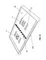
- FIG. 9is a bottom perspective view of an embodiment where a plurality of cooling channels are created between the backlight assembly and the isolating structure.
- FIG. 10is bottom plan view of an exemplary embodiment of a cooling channel containing a power module.
- FIG. 11is a top perspective view of an embodiment where a fan is placed at the top of each cooling channel.
- Embodimentsprovide a plurality of different systems and methods for cooling electronic displays. Embodiments may be used for displays which are operated near room temperature. Exemplary embodiments may be used with displays which are operated outdoors and even in direct sunlight. Performance in temperatures as high as 113° F. and above are possible.
- embodimentsmay be used in conjunction with any of the following: LCD (all types), light emitting diode (LED), organic light emitting diode (OLED), field emitting display (FED), and plasma displays.
- LCDall types
- LEDlight emitting diode
- OLEDorganic light emitting diode
- FEDfield emitting display
- embodimentsmay be used with displays of other types including those not yet discovered.
- the systemmay be well suited for use with full color, flat panel OLED displays.
- Exemplary embodimentsmay also utilize large (55 inches or more) LED backlit, high definition (1080i or 1080p or greater) liquid crystal displays (LCD). While the embodiments described herein are well suited for outdoor environments, they may also be appropriate for indoor applications (e.g., factory/industrial environments, spas, locker rooms) where thermal stability of the display may be at risk.
- FIG. 1shows an embodiment of a power module 7 which may be used with some exemplary embodiments.
- a printed circuit board 6may be attached to the power module 7 and may contain a plurality of electronic components 5 which may be necessary to operate and control the power module 7 . These electronic components 5 may include, but are no means limited to resistors, capacitors, op-amps, wire harnesses, connectors, and inductors.
- a baseplate 8may be attached to the power module 7 and may act as a heat dissipating assembly for the power module 7 , such that heat which is generated by the power module 7 is transferred to the baseplate 8 . In some embodiments there may be more components used, such as a conductive pad located between the power module and the baseplate 8 . Also, as discussed further below, any type of heat sink or fin assembly may be used with the baseplate 8 to further enhance its thermodynamic properties. There may be conductive pads placed between the baseplate 8 and a heat sink assembly also.
- An exemplary power modulewould be any type which uses heat dissipating assemblies.
- An exemplary power moduleis commercially available from TDK-Lambda of San Diego, Calif. www.lambdapower.com.
- the PFE series of power modulescould be used with exemplary embodiments.
- FIG. 2shows two power modules installed within an isolating structure 9 which substantially prevents gaseous communication between the two sides of the power module.
- the baseplates 8 of the power modulesare shown on the side of the isolating structure 9 where ambient gas 4 may be used to pass over the baseplates 8 .
- Gaskets 11may be used to provide a gaseous seal between the power modules and the isolating structure 9 .
- the ambient gas 4is sometimes drawn from the environment surrounding the display and may or may not be treated or filtered. This environment may contain harmful contaminates which could damage various electrical components in the display. These harmful contaminates include, but are not limited to: dust, smoke, pollen, water vapor, other harmful particulate and other harmful gases.
- one of the purposes for the isolating structure 9is to prevent the ambient gas 4 from contacting some of the sensitive electronic components of the display, including but not limited to the electronic components 5 which are required to operate and control the power modules.
- ambient gas 4can be drawn into the display housing and forced over the baseplates and optional heatsinks and fins in order to cool the power modules. This can be accomplished without exposing sensitive electronic components to the potentially harmful ambient gas 4 .
- FIG. 3Ashows an embodiment where the ambient gas 4 may be used to cool both the power modules and the backlight assembly 140 .
- a backlight assembly 140which is comprised of a plurality of LEDs 141 which are mounted to a mounting substrate, preferably a printed circuit board (PCB).
- PCBprinted circuit board
- An exemplary embodimentwould use a metal core PCB or any other mounting structure which would have a relatively low level of thermal resistance so that heat can transfer from the LEDs 141 to the rear surface of the backlight assembly 140 where it can be removed by the ambient gas 4 .
- this type of backlight assemblyis not required, as other types including but not limited to CCFL backlights can also be used.
- a backlight assemblymay not even be necessary for some embodiments such as plasma and OLED displays. However, these display types are also known to generate heat and where backlight cooling is described in this application these methods could also be applied to the cooling of rear surfaces of these display assemblies. Thus, where backlight assemblies are shown, a plasma or OLED display assembly could be substitute
- FIG. 3Bshows the rear view of the embodiment shown in FIG. 3A . From this view, the electronic components 5 are shown as being isolated from the ambient gas 4 .
- FIG. 4shows an embodiment which is similar to that which was shown in FIGS. 3A-3B with the exception that a heat sink 12 is now being used with the power modules in order to further facilitate the transfer of heat away from the power modules.
- a heat sink 12is now being used with the power modules in order to further facilitate the transfer of heat away from the power modules.
- many types of heat sinksare available which are made of many different materials and have many different geometry types. Any form of heat sink is particularly contemplated with various embodiments and may satisfy different operating conditions.
- FIG. 5shows an exemplary embodiment for an electronic display 10 which includes an isolated gas cooling system 20 contained within an electronic display housing 70 .
- a narrow transparent first gas chamberis defined by spacers 100 and transparent front plate 90 .
- a second transparent front plate 130may be laminated to front plate 90 to help prevent breakage of front plate 90 (or provide optical properties).
- the isolated gas cooling system 20may surround the display assembly 80 and associated backlight assembly 140 (if the backlight is necessary). If used with an LCD display, the display assembly 80 may comprise an LCD stack.
- the isolated gas cooling system 20may include a means for cooling the isolated gas contained within the second gas chamber 40 .
- This meansmay include one or more fans 60 which may be positioned at the base of the display housing 70 .
- the fansmay force ambient gas 4 (shown in FIG. 6 ) over at least one external surface of a cooling plenum 45 .
- an air conditioner(not shown) may also be utilized to cool the air prior to contacting the air with the external surfaces of the plenum 45 .
- Surface featuressuch as fins or heat sinks (not shown) may be placed on the exterior surfaces of the plenum 45 to further aid the plenum's ability to dissipate heat.
- a heat exchangermay be used to cool the isolated gas contained within the second gas chamber 40 .
- the heat exchanger system described in co-pending application 61/138736 filed on Dec. 18, 2008may be used with any of the isolated gas cooling systems referenced herein and this application is herein incorporated by reference in its entirety.
- FIG. 6shows one method for removing heat from the isolated gas contained in the rear plenum 45 .
- One or more fans 60may be positioned to ingest ambient gas 4 and blow that ambient gas 4 into the display housing 70 .
- the ambient gaswill contact the front and rear surfaces of the plenum 45 .
- fans 60may also force ambient gas 4 past the heat generating components of the electronic display (e.g., the display assembly 80 and the backlight assembly 140 ) to further improve the cooling capability of the overall system.
- the heated exhaust airmay exit through one or more exhaust apertures 179 located on the display housing 70 .
- the ingested ambient gas 4may be air conditioned prior to being ingested into the display housing 70 .
- one or more air-drawing fans 17may be used instead of, or in addition to the fans 60 in order to draw ingested ambient gas in between the backlight assembly 140 and the cooling plenum 45 , between the backlight assembly 140 and an isolating structure 9 , or between a display assembly 80 and an isolating structure 9 .
- the isolated gas cooling system 20may comprise a closed loop which includes a first gas chamber 30 and a second gas chamber 40 .
- the first gas chamberincludes a transparent plate 90 .
- the second gas chambercomprises a cooling plenum 45 .
- isolated gasrefers to the fact that the gas within the isolated gas cooling chamber 20 is essentially isolated from ambient gas which may be drawn into the housing of the display. Because the first gas chamber 30 is positioned in front of the display image, the gas should be substantially free of dust or other contaminates that might negatively affect the display image.
- the isolated gasmay be almost any transparent gas, for example, normal air, nitrogen, helium, or any other transparent gas.
- the gasis preferably colorless so as not to affect the image quality.
- the isolated gas cooling system 20need not necessarily be hermetically sealed from the external air. It is sufficient that the gas is isolated to the extent that dust and contaminates may not substantially enter the first gas chamber.
- One or more filtersmay also be used to ensure that any contaminates which may enter the isolated gas system become trapped and cannot impair the image quality.
- the first gas chamber 30is in gaseous communication with the second gas chamber 40 .
- One or more cooling chamber fans 50may be provided within the second gas chamber 40 .
- the cooling fans 50may be utilized to propel gas around the isolated gas cooling chamber 20 .
- the first gas chamber 30includes at least one transparent front plate 90 mounted in front of an electronic display surface 85 .
- the front plate 90may be set forward from the electronic display surface 85 by spacers 100 (see FIG. 5 ).
- the spacing members 100may define the depth of the channel passing in front of the electronic display surface 85 .
- the spacing members 100may be independent or alternatively may be integral with some other component of the device (e.g., integral with the front plate).
- the electronic display surface 85 , the spacing members 100 , and the transparent front plate 90may define a first gas chamber 30 .
- the chamber 30is in gaseous communication with the second chamber 40 through entrance opening 110 and exit opening 120 .
- a rear surface of the first gas chamber 30preferably comprises the electronic display surface 85 of the display assembly 80 . As the isolated gas in the first gas chamber 30 traverses the display it contacts the electronic display surface 85 . Contacting the isolated gas directly to the electronic display surface 85 enhances the convective heat transfer away from the electronic display surface 85 .
- the electronic display surface 85 of a typical displayis glass. However, neither electronic display surface 85 , nor transparent front plate 90 , nor optional second transparent front plate 130 need necessarily be glass. By utilizing the electronic display surface 85 as the rear surface wall of the first gas chamber 30 , there may be fewer surfaces to impact the visible light traveling through the display. Furthermore, the device will be lighter and cheaper to manufacturer. This is not necessary however.
- the embodiment shownutilizes the electronic display surface 85 as the rear surface of the first gas chamber 30
- certain modifications and/or coatingse.g., anti-reflective coatings
- the electronic display surface 85may be the front glass plate of a liquid crystal display (LCD) stack.
- LCDliquid crystal display
- almost any display surfacemay be suitable for embodiments of the present cooling system, including but not limited to plasma and OLED displays.
- the convective effect of the isolated gaswill be maximized and heat can be more effectively removed from the display assembly itself.
- the isolated gas, which has absorbed heat from the electronic display surface 85may then be diverted to the cooling plenum 45 where the collected heat energy in the gas may be dissipated into the walls of the plenum 45 where it can then be transferred to the surrounding air and exhausted from the display housing 70 .
- the isolated gas cooling system 20may be designed to move the gas in either a horizontal or a vertical direction, it is preferable to propel the gas in a horizontal direction. In this way, if dust or contaminates do enter the first gas chamber 30 , they will tend to fall to the bottom of chamber 30 outside of the viewable area of the display.
- the systemmay move air left to right, or alternatively, right to left.
- Section line 8 a - 8 ais shown which removes all portions of the isolated gas system 20 from the section line towards the front of the display.
- Section line 8 b - 8 bis also shown which removes the rear wall of the second gas chamber 40 .
- FIG. 8shows a perspective view of the interior of the second gas chamber 40 .
- power modulesare mounted within the front wall of the second gas chamber 40 .
- Cooling chamber fans 50propel the isolated gas 21 around the isolated gas cooling system.
- the electronic components 5 of the power modulesare exposed to the isolated gas 21 for additional cooling.
- the isolated gas 21as discussed at length above, is designed to be substantially free of contaminates and thus should be permitted to contact the electronic components 5 without the risk of damage.
- ambient gasmay be forced between the backlight assembly 140 (or display assembly) and the exterior wall of the second gas chamber 40 (plenum) and may contact power module baseplates 8 (not shown) or heat sinks 12 (not shown) in order to further cool the power modules.
- any of the isolated gas systems described in any of the co-pending application Ser. No. 12/234,307 filed on Sep. 19, 2008, Ser. No. 12/234,360 filed on Sep. 19, 2008, Ser. Nos. 12/237,365 filed on Sep. 24, 2008, and 61/115,333 filed on Nov. 17, 2008, and Ser. No. 12/641,468 filed on Dec. 18, 2009may be used with any of the embodiments herein and are herein incorporated by reference in their entirety.
- a cross-flow heat exchangermay be substituted for the second gas chamber 40 shown in FIG. 8 .
- FIG. 9shows an exemplary embodiment where a plurality of channels 15 are created between the backlight assembly 140 and the isolating structure 9 .
- Channel separators 16may be used to separate each channel 15 and provide structural rigidity to the overall assembly.
- the channel separators 16should preferably be fabricated out of thermally conductive material so that they may also transfer heat between the backlight assembly 140 and the isolating structure 9 .
- a thermally conductive channel separator 16can also extract heat from either the backlight assembly 140 or the isolating structure 9 and may dissipate the heat into the air moving through the channel 15 .
- some channel separators 16may contain fins or heat sinks in order to facilitate heat transfer to the air moving through the channel 15 .
- FIG. 10shows a view down a single channel 15 which contains the heat sink 12 for a power module which is mounted within the isolating structure 9 .
- Some channels 15may contain power modules and others may not.
- a channel fan 17may be used to draw air through the channel in order to cool the heat sink 12 (if used) and the channel separators 16 (if thermally conductive).
- Each channel 15may contain one or more channel fans 17 .
- Some channelsmay not contain a fan at all, but may rely solely on natural convection to allow heat to rise and exit the channel.
- fans 60near the base of the display may be used instead of or in addition to the channel fans 17 .
- FIG. 11shows an embodiment where a channel fan 17 is used with each channel 15 . While the display is in operation, the channel fans 17 may run continuously. Alternatively, temperature sensing devices (not shown) may be placed in each channel and used to measure the temperature of the air within the channel or any of the channel components (backlight or display assembly, isolating structure, or channel separators). Based on information received from these temperature sensing devices, the various fans may be selectively engaged depending on which channel requires cooling. Thus, fans 17 which draw air through channels 15 which contain power modules may run more often or at higher speeds due to the greater amount of heat coming from the power modules. Also, channels which contain power modules may contain larger fans or a plurality of fans in order to cool the channel.
- the isolated gas cooling systemmay also run continuously.
- temperature sensing devicesmay be incorporated within the electronic display to detect when temperatures have reached a predetermined threshold value.
- the cooling chamber fans 50may be selectively engaged when the temperature in the display reaches a predetermined value.
- Predetermined thresholdsmay be selected and the system may be configured to advantageously keep the display within an acceptable temperature range.
- Typical thermostat assembliescan be used to accomplish this task.
- Thermocouplesmay be used as the temperature sensing devices.
- the various embodiments showncan be combined in a number of ways to provide adequate thermal regulation of displays which may be used in a number of different environments. Further, measuring the temperature at various points in the display and selectively engaging the various fans or cooling systems allows the display to use less energy by selectively cooling only portions of the display. This will also increase the life of any cooling fans as they will not be required to run continuously.
Landscapes
- Physics & Mathematics (AREA)
- Engineering & Computer Science (AREA)
- Microelectronics & Electronic Packaging (AREA)
- Nonlinear Science (AREA)
- Thermal Sciences (AREA)
- Mathematical Physics (AREA)
- Chemical & Material Sciences (AREA)
- Crystallography & Structural Chemistry (AREA)
- General Physics & Mathematics (AREA)
- Optics & Photonics (AREA)
- Devices For Indicating Variable Information By Combining Individual Elements (AREA)
Abstract
Description
Claims (17)
Priority Applications (25)
| Application Number | Priority Date | Filing Date | Title |
|---|---|---|---|
| US12/706,652US8358397B2 (en) | 2008-03-03 | 2010-02-16 | System for cooling an electronic display |
| US12/753,298US8351014B2 (en) | 2008-03-03 | 2010-04-02 | Heat exchanger for back to back electronic displays |
| US12/905,704US8773633B2 (en) | 2008-03-03 | 2010-10-15 | Expanded heat sink for electronic displays |
| US12/915,718US8760613B2 (en) | 2008-12-18 | 2010-10-29 | Modular distributed components for LED backlight |
| US12/952,745US8693185B2 (en) | 2008-03-26 | 2010-11-23 | System and method for maintaining a consistent temperature gradient across an electronic display |
| PCT/US2010/058925WO2011069084A2 (en) | 2009-12-03 | 2010-12-03 | Thermal plate with optional cooling loop in electronic display |
| PCT/US2010/059878WO2011072217A2 (en) | 2009-12-10 | 2010-12-10 | Modular distributed components for led backlight |
| US13/100,556US8749749B2 (en) | 2008-12-18 | 2011-05-04 | System for cooling an electronic image assembly with manifolds and ambient gas |
| US13/100,580US8823916B2 (en) | 2008-03-03 | 2011-05-04 | System for cooling an electronic image assembly with a heat exchanger having internal fans |
| US13/179,996US8369083B2 (en) | 2010-02-16 | 2011-07-11 | System and method for selectively engaging cooling fans within an electronic display |
| US13/692,657US9030641B2 (en) | 2008-03-03 | 2012-12-03 | Heat exchanger for back to back electronic displays |
| US13/747,226US20130170140A1 (en) | 2008-03-03 | 2013-01-22 | System for Cooling an Electronic Display |
| US13/759,744US8649170B2 (en) | 2010-02-16 | 2013-02-05 | System and method for selectively engaging cooling fans within an electronic display |
| US14/247,658US9594271B2 (en) | 2008-03-26 | 2014-04-08 | System and method for maintaining a consistent temperature gradient across an electronic display |
| US14/300,869US8988647B2 (en) | 2008-12-18 | 2014-06-10 | System for cooling an electronic image assembly with manifolds and ambient gas |
| US14/326,053US9285108B2 (en) | 2008-03-03 | 2014-07-08 | Expanded heat sink for electronic displays |
| US14/475,173US9119330B2 (en) | 2008-03-03 | 2014-09-02 | System for cooling an electronic image assembly with a heat exchanger having internal fans |
| US14/664,213US9549490B2 (en) | 2008-12-18 | 2015-03-20 | System for cooling an electronic image assembly with circulating gas and ambient gas |
| US14/702,443US9173325B2 (en) | 2008-03-26 | 2015-05-01 | Heat exchanger for back to back electronic displays |
| US14/923,164US9835893B2 (en) | 2008-03-03 | 2015-10-26 | Heat exchanger for back to back electronics displays |
| US15/069,154US9797588B2 (en) | 2008-03-03 | 2016-03-14 | Expanded heat sink for electronic displays |
| US15/407,131US10314212B2 (en) | 2008-12-18 | 2017-01-16 | System for cooling an electronic image assembly with circulating gas and ambient gas |
| US15/456,117US10420257B2 (en) | 2008-03-26 | 2017-03-10 | System and method for maintaining a consistent temperature gradient across an electronic display |
| US16/430,195US10827656B2 (en) | 2008-12-18 | 2019-06-03 | System for cooling an electronic image assembly with circulating gas and ambient gas |
| US17/061,753US11191193B2 (en) | 2008-12-18 | 2020-10-02 | System for cooling an electronic image assembly with circulating gas and ambient gas |
Applications Claiming Priority (20)
| Application Number | Priority Date | Filing Date | Title |
|---|---|---|---|
| US3306408P | 2008-03-03 | 2008-03-03 | |
| US3945408P | 2008-03-26 | 2008-03-26 | |
| US5371308P | 2008-05-16 | 2008-05-16 | |
| US5759908P | 2008-05-30 | 2008-05-30 | |
| US7612608P | 2008-06-26 | 2008-06-26 | |
| US9561608P | 2008-09-09 | 2008-09-09 | |
| US9561508P | 2008-09-09 | 2008-09-09 | |
| US12/234,307US8767165B2 (en) | 2007-11-16 | 2008-09-19 | Isolated gas cooling system for an electronic display |
| US12/234,360US20090126914A1 (en) | 2007-11-16 | 2008-09-19 | Isolated Gas Cooling System for Cooling Electrical Components of an Electronic Display |
| US12/235,200US20090126907A1 (en) | 2007-11-16 | 2008-09-22 | Isolated Gas Heating System for an Electronic Display |
| US12/237,365US8879042B2 (en) | 2007-11-16 | 2008-09-24 | Isolated cooling system having an insulator gap and front polarizer |
| US11533308P | 2008-11-17 | 2008-11-17 | |
| US13873608P | 2008-12-18 | 2008-12-18 | |
| US15287909P | 2009-02-16 | 2009-02-16 | |
| US12/411,925US8854595B2 (en) | 2008-03-03 | 2009-03-26 | Constricted convection cooling system for an electronic display |
| US12/556,029US8373841B2 (en) | 2007-11-16 | 2009-09-09 | Shared isolated gas cooling system for oppositely facing electronic displays |
| US12/556,209US8379182B2 (en) | 2007-11-16 | 2009-09-09 | Cooling system for outdoor electronic displays |
| US12/620,330US8274622B2 (en) | 2008-03-03 | 2009-11-17 | System for using constricted convection with closed loop plenum as the convection plate |
| US12/641,468US8654302B2 (en) | 2008-03-03 | 2009-12-18 | Heat exchanger for an electronic display |
| US12/706,652US8358397B2 (en) | 2008-03-03 | 2010-02-16 | System for cooling an electronic display |
Related Parent Applications (14)
| Application Number | Title | Priority Date | Filing Date |
|---|---|---|---|
| US12/234,307Continuation-In-PartUS8767165B2 (en) | 2007-11-16 | 2008-09-19 | Isolated gas cooling system for an electronic display |
| US12/234,360Continuation-In-PartUS20090126914A1 (en) | 2007-11-16 | 2008-09-19 | Isolated Gas Cooling System for Cooling Electrical Components of an Electronic Display |
| US12/235,200Continuation-In-PartUS20090126907A1 (en) | 2007-11-16 | 2008-09-22 | Isolated Gas Heating System for an Electronic Display |
| US12/237,365Continuation-In-PartUS8879042B2 (en) | 2007-11-16 | 2008-09-24 | Isolated cooling system having an insulator gap and front polarizer |
| US12/411,925Continuation-In-PartUS8854595B2 (en) | 2007-11-16 | 2009-03-26 | Constricted convection cooling system for an electronic display |
| US12/556,029Continuation-In-PartUS8373841B2 (en) | 2007-11-16 | 2009-09-09 | Shared isolated gas cooling system for oppositely facing electronic displays |
| US12/556,209Continuation-In-PartUS8379182B2 (en) | 2007-11-16 | 2009-09-09 | Cooling system for outdoor electronic displays |
| US12/620,330Continuation-In-PartUS8274622B2 (en) | 2008-03-03 | 2009-11-17 | System for using constricted convection with closed loop plenum as the convection plate |
| US12/630,469Continuation-In-PartUS8497972B2 (en) | 2008-03-03 | 2009-12-03 | Thermal plate with optional cooling loop in electronic display |
| US12/641,468Continuation-In-PartUS8654302B2 (en) | 2008-03-03 | 2009-12-18 | Heat exchanger for an electronic display |
| US12/753,298Continuation-In-PartUS8351014B2 (en) | 2008-03-03 | 2010-04-02 | Heat exchanger for back to back electronic displays |
| US12/905,704Continuation-In-PartUS8773633B2 (en) | 2008-03-03 | 2010-10-15 | Expanded heat sink for electronic displays |
| US12/952,745Continuation-In-PartUS8693185B2 (en) | 2008-03-26 | 2010-11-23 | System and method for maintaining a consistent temperature gradient across an electronic display |
| US13/100,556Continuation-In-PartUS8749749B2 (en) | 2008-12-18 | 2011-05-04 | System for cooling an electronic image assembly with manifolds and ambient gas |
Related Child Applications (10)
| Application Number | Title | Priority Date | Filing Date |
|---|---|---|---|
| US12/556,209Continuation-In-PartUS8379182B2 (en) | 2007-11-16 | 2009-09-09 | Cooling system for outdoor electronic displays |
| US12/620,330Continuation-In-PartUS8274622B2 (en) | 2008-03-03 | 2009-11-17 | System for using constricted convection with closed loop plenum as the convection plate |
| US12/641,468Continuation-In-PartUS8654302B2 (en) | 2008-03-03 | 2009-12-18 | Heat exchanger for an electronic display |
| US12/753,298Continuation-In-PartUS8351014B2 (en) | 2008-03-03 | 2010-04-02 | Heat exchanger for back to back electronic displays |
| US12/905,704Continuation-In-PartUS8773633B2 (en) | 2008-03-03 | 2010-10-15 | Expanded heat sink for electronic displays |
| US12/952,745Continuation-In-PartUS8693185B2 (en) | 2008-03-26 | 2010-11-23 | System and method for maintaining a consistent temperature gradient across an electronic display |
| US13/100,580Continuation-In-PartUS8823916B2 (en) | 2008-03-03 | 2011-05-04 | System for cooling an electronic image assembly with a heat exchanger having internal fans |
| US13/100,556Continuation-In-PartUS8749749B2 (en) | 2008-12-18 | 2011-05-04 | System for cooling an electronic image assembly with manifolds and ambient gas |
| US13/179,996Continuation-In-PartUS8369083B2 (en) | 2010-02-16 | 2011-07-11 | System and method for selectively engaging cooling fans within an electronic display |
| US13/747,226ContinuationUS20130170140A1 (en) | 2008-03-03 | 2013-01-22 | System for Cooling an Electronic Display |
Publications (2)
| Publication Number | Publication Date |
|---|---|
| US20100238394A1 US20100238394A1 (en) | 2010-09-23 |
| US8358397B2true US8358397B2 (en) | 2013-01-22 |
Family
ID=42737268
Family Applications (2)
| Application Number | Title | Priority Date | Filing Date |
|---|---|---|---|
| US12/706,652Active2029-09-01US8358397B2 (en) | 2008-03-03 | 2010-02-16 | System for cooling an electronic display |
| US13/747,226AbandonedUS20130170140A1 (en) | 2008-03-03 | 2013-01-22 | System for Cooling an Electronic Display |
Family Applications After (1)
| Application Number | Title | Priority Date | Filing Date |
|---|---|---|---|
| US13/747,226AbandonedUS20130170140A1 (en) | 2008-03-03 | 2013-01-22 | System for Cooling an Electronic Display |
Country Status (1)
| Country | Link |
|---|---|
| US (2) | US8358397B2 (en) |
Cited By (46)
| Publication number | Priority date | Publication date | Assignee | Title |
|---|---|---|---|---|
| US20130170140A1 (en)* | 2008-03-03 | 2013-07-04 | Manufacturing Resources International, Inc. | System for Cooling an Electronic Display |
| US8842253B2 (en) | 2008-06-13 | 2014-09-23 | Samsung Electronics Co., Ltd. | Liquid crystal display device having air conditioner |
| US9451060B1 (en) | 2015-10-15 | 2016-09-20 | Civiq Smartscapes, Llc | Techniques and apparatus for controlling access to components of a personal communication structure (PCS) |
| US9516485B1 (en) | 2015-11-13 | 2016-12-06 | Civiq Smartscapes, Llc | Systems and methods for making emergency phone calls |
| US9622392B1 (en) | 2015-09-17 | 2017-04-11 | Civiq Smartscapes, Llc | Techniques and apparatus for controlling the temperature of a personal communication structure (PCS) |
| US9703320B2 (en) | 2015-09-17 | 2017-07-11 | Civiq Smartscapes, Llc | Techniques and apparatus for mounting a housing on a personal communication structure (PCS) |
| US9797588B2 (en) | 2008-03-03 | 2017-10-24 | Manufacturing Resources International, Inc. | Expanded heat sink for electronic displays |
| US9823690B2 (en) | 2015-09-11 | 2017-11-21 | Civiq Smartscapes, Llc | Techniques and apparatus for securing a structure to a support |
| US9835893B2 (en) | 2008-03-03 | 2017-12-05 | Manufacturing Resources International, Inc. | Heat exchanger for back to back electronics displays |
| US9894800B2 (en) | 2008-03-03 | 2018-02-13 | Manufacturing Resources International, Inc. | Constricted convection cooling system for an electronic display |
| US10080316B2 (en) | 2009-11-13 | 2018-09-18 | Manufacturing Resources International, Inc. | Electronic display assembly having thermal cooling plate and optional convective air cooling loop |
| US10088702B2 (en) | 2013-07-08 | 2018-10-02 | Manufacturing Resources International, Inc. | Figure eight closed loop cooling system for electronic display |
| US10127781B2 (en) | 2015-11-16 | 2018-11-13 | Civiq Smartscapes, Llc | Systems and techniques for vandalism detection in a personal communication structure (PCS) |
| US10194564B2 (en) | 2014-04-30 | 2019-01-29 | Manufacturing Resources International, Inc. | Back to back electronic display assembly |
| US10212845B2 (en) | 2014-03-11 | 2019-02-19 | Manufacturing Resources International, Inc. | Hybrid rear cover and mounting bracket for electronic display |
| US10270918B2 (en) | 2015-10-15 | 2019-04-23 | Civiq Smartscapes, Llc | Method and apparatus for power and temperature control of compartments within a personal communication structure (PCS) |
| US10278311B2 (en) | 2015-02-17 | 2019-04-30 | Manufacturing Resources International, Inc. | Perimeter ventilation system |
| US10314212B2 (en) | 2008-12-18 | 2019-06-04 | Manufacturing Resources International, Inc. | System for cooling an electronic image assembly with circulating gas and ambient gas |
| US10398066B2 (en) | 2017-04-27 | 2019-08-27 | Manufacturing Resources International, Inc. | System and method for preventing display bowing |
| US10420257B2 (en) | 2008-03-26 | 2019-09-17 | Manufacturing Resources International, Inc. | System and method for maintaining a consistent temperature gradient across an electronic display |
| US10485113B2 (en) | 2017-04-27 | 2019-11-19 | Manufacturing Resources International, Inc. | Field serviceable and replaceable display |
| US10506740B2 (en) | 2008-03-03 | 2019-12-10 | Manufacturing Resources International, Inc. | Electronic display with cooling |
| US10524397B2 (en) | 2013-03-15 | 2019-12-31 | Manufacturing Resources International, Inc. | Heat exchanger assembly for an electronic display |
| US10524384B2 (en) | 2013-03-15 | 2019-12-31 | Manufacturing Resources International, Inc. | Cooling assembly for an electronic display |
| US10559965B2 (en) | 2017-09-21 | 2020-02-11 | Manufacturing Resources International, Inc. | Display assembly having multiple charging ports |
| US10660245B2 (en) | 2012-10-16 | 2020-05-19 | Manufacturing Resources International, Inc. | Back pan cooling assembly for electronic display |
| US10795413B1 (en) | 2019-04-03 | 2020-10-06 | Manufacturing Resources International, Inc. | Electronic display assembly with a channel for ambient air in an access panel |
| US10820445B2 (en) | 2016-03-04 | 2020-10-27 | Manufacturing Resources International, Inc. | Cooling system for double sided display assembly |
| US10827656B2 (en) | 2008-12-18 | 2020-11-03 | Manufacturing Resources International, Inc. | System for cooling an electronic image assembly with circulating gas and ambient gas |
| US10878654B2 (en) | 2018-06-28 | 2020-12-29 | Ags Llc | Closed loop cabinet cooling |
| US11019735B2 (en) | 2018-07-30 | 2021-05-25 | Manufacturing Resources International, Inc. | Housing assembly for an integrated display unit |
| US11096317B2 (en) | 2019-02-26 | 2021-08-17 | Manufacturing Resources International, Inc. | Display assembly with loopback cooling |
| US11470749B2 (en) | 2020-10-23 | 2022-10-11 | Manufacturing Resources International, Inc. | Forced air cooling for display assemblies using centrifugal fans |
| US11477923B2 (en) | 2020-10-02 | 2022-10-18 | Manufacturing Resources International, Inc. | Field customizable airflow system for a communications box |
| US11744054B2 (en) | 2021-08-23 | 2023-08-29 | Manufacturing Resources International, Inc. | Fan unit for providing improved airflow within display assemblies |
| US11762231B2 (en) | 2021-08-23 | 2023-09-19 | Manufacturing Resources International, Inc. | Display assemblies inducing turbulent flow |
| US11778757B2 (en) | 2020-10-23 | 2023-10-03 | Manufacturing Resources International, Inc. | Display assemblies incorporating electric vehicle charging equipment |
| US11919393B2 (en) | 2021-08-23 | 2024-03-05 | Manufacturing Resources International, Inc. | Display assemblies inducing relatively turbulent flow and integrating electric vehicle charging equipment |
| US11966263B2 (en) | 2021-07-28 | 2024-04-23 | Manufacturing Resources International, Inc. | Display assemblies for providing compressive forces at electronic display layers |
| US11968813B2 (en) | 2021-11-23 | 2024-04-23 | Manufacturing Resources International, Inc. | Display assembly with divided interior space |
| US12010813B2 (en) | 2022-07-22 | 2024-06-11 | Manufacturing Resources International, Inc. | Self-contained electronic display assembly, mounting structure and methods for the same |
| US12035486B1 (en) | 2022-07-25 | 2024-07-09 | Manufacturing Resources International, Inc. | Electronic display assembly with fabric panel communications box |
| US12072561B2 (en) | 2022-07-22 | 2024-08-27 | Manufacturing Resources International, Inc. | Self-contained electronic display assembly, mounting structure and methods for the same |
| US12127383B2 (en) | 2007-11-16 | 2024-10-22 | Manufacturing Resources International, Inc. | Electronic display assembly with thermal management |
| US12408312B2 (en) | 2021-07-28 | 2025-09-02 | Manufacturing Resources International, Inc. | Display assemblies with vents |
| US12443067B2 (en) | 2023-07-14 | 2025-10-14 | Manufacturing Resources International, Inc. | Display assemblies inducing turbulent flow |
Families Citing this family (20)
| Publication number | Priority date | Publication date | Assignee | Title |
|---|---|---|---|---|
| CN101592807A (en)* | 2008-05-27 | 2009-12-02 | 深圳市新超亮特种显示设备有限公司 | A kind of LCDs with heat abstractor |
| JP5241414B2 (en)* | 2008-09-30 | 2013-07-17 | 三洋電機株式会社 | Image display device |
| US9046255B2 (en)* | 2011-05-18 | 2015-06-02 | Sharp Kabushiki Kaisha | Illumination device and display device |
| US9459001B2 (en) | 2011-06-10 | 2016-10-04 | Martin Professional A/S | Illumination device with multi-layered heat sink |
| US9881528B2 (en) | 2011-10-13 | 2018-01-30 | Manufacturing Resources International, Inc. | Transparent liquid crystal display on display case |
| US10852025B2 (en) | 2013-04-30 | 2020-12-01 | Ademco Inc. | HVAC controller with fixed segment display having fixed segment icons and animation |
| US9633366B2 (en) | 2014-06-16 | 2017-04-25 | Manufacturing Resources International, Inc. | System for tracking and analyzing display case usage |
| US9500896B2 (en) | 2014-06-16 | 2016-11-22 | Manufacturing Resources International, Inc. | Cooling system for liquid crystal display |
| US9526352B2 (en) | 2014-06-16 | 2016-12-27 | Manufacturing Resources International, Inc. | Wireless video transmission system for liquid crystal display |
| US9535293B2 (en) | 2014-06-16 | 2017-01-03 | Manufacturing Resources International, Inc. | Sealed transparent liquid crystal display assembly |
| US9500801B2 (en) | 2014-06-16 | 2016-11-22 | Manufacturing Resources International, Inc. | LED assembly for transparent liquid crystal display |
| US10649273B2 (en) | 2014-10-08 | 2020-05-12 | Manufacturing Resources International, Inc. | LED assembly for transparent liquid crystal display and static graphic |
| US9832847B2 (en) | 2014-10-09 | 2017-11-28 | Manufacturing Resources International, Inc. | System for decreasing energy usage of a transparent LCD display case |
| US10182665B2 (en) | 2014-10-15 | 2019-01-22 | Manufacturing Resources International, Inc. | System and method for preventing damage to products |
| JP2019513251A (en) | 2016-03-02 | 2019-05-23 | マニュファクチャリング・リソーシズ・インターナショナル・インコーポレーテッド | Vending machine with transparent display |
| WO2018009399A1 (en) | 2016-07-08 | 2018-01-11 | Manufacturing Resources International, Inc. | Mirror having an integrated electronic display |
| KR102543859B1 (en)* | 2017-12-22 | 2023-06-16 | 삼성전자주식회사 | Display apparatus |
| CN110505795B (en)* | 2019-08-26 | 2020-09-11 | 深圳市易光科技有限公司 | LED driving power supply with overheat protection function |
| US11943893B2 (en)* | 2019-10-26 | 2024-03-26 | Vertiv Corporation | Electronics equipment cabinets for housing electronic devices |
| CN219737936U (en)* | 2023-05-11 | 2023-09-22 | 上海启钧电子有限公司 | High brightness liquid crystal display device |
Citations (47)
| Publication number | Priority date | Publication date | Assignee | Title |
|---|---|---|---|---|
| US4093355A (en) | 1977-02-04 | 1978-06-06 | General Motors Corporation | Symmetrical internal heater for liquid crystal display |
| US4593978A (en) | 1983-03-18 | 1986-06-10 | Thomson-Csf | Smectic liquid crystal color display screen |
| US4634225A (en) | 1984-12-24 | 1987-01-06 | General Electric Co. | Transflective liquid crystal display with integral heating unit and temperature sensor |
| JPH03153212A (en) | 1989-11-10 | 1991-07-01 | Hitachi Ltd | Liquid crystal display device |
| US5029982A (en) | 1989-09-11 | 1991-07-09 | Tandy Corporation | LCD contrast adjustment system |
| US5088806A (en) | 1990-01-16 | 1992-02-18 | Honeywell, Inc. | Apparatus and method for temperature compensation of liquid crystal matrix displays |
| US5247374A (en) | 1990-04-05 | 1993-09-21 | Stanley Electric Co., Ltd. | Liquid crystal display device with common heater between two cells |
| JPH08194437A (en) | 1995-01-13 | 1996-07-30 | Matsushita Electric Works Ltd | Display device |
| US5559614A (en) | 1995-05-01 | 1996-09-24 | Motorola, Inc. | Liquid crystal display with integral heater and method of fabricating same |
| US5748269A (en) | 1996-11-21 | 1998-05-05 | Westinghouse Air Brake Company | Environmentally-sealed, convectively-cooled active matrix liquid crystal display (LCD) |
| US5767489A (en) | 1994-12-14 | 1998-06-16 | Hewlett-Packard Company | Enhanced resolution liquid crystal microthermography method and apparatus |
| US5818010A (en) | 1995-10-31 | 1998-10-06 | Smiths Industries Plc | Display assemblies |
| US5869919A (en) | 1994-06-09 | 1999-02-09 | Canon Kabushiki Kaisha | Air cooling for flat panel displays |
| JPH11160727A (en) | 1997-12-01 | 1999-06-18 | Advanced Display Inc | Liquid crystal display device |
| US5991153A (en) | 1997-10-31 | 1999-11-23 | Lacerta Enterprises, Inc. | Heat transfer system and method for electronic displays |
| US6089751A (en) | 1996-12-30 | 2000-07-18 | Honeywell Inc. | Transparent temperature sensor for an active matrix liquid crystal display |
| US6157432A (en) | 1999-01-29 | 2000-12-05 | Hewlett-Packard Company | Heated ferroelectric liquid crystal spatial light modulator with improved contrast, improved grayscale resolution, and decreased pixel sticking when operated in a non-DC balanced mode |
| US6191839B1 (en) | 1999-05-03 | 2001-02-20 | Rockwell Collin, Inc. | Patterned thermal sensor |
| JP2002158475A (en) | 2000-11-20 | 2002-05-31 | Fujitsu General Ltd | Sealed housing for flat panel display |
| US6417900B1 (en) | 1997-03-21 | 2002-07-09 | Lg. Philips Lcd Co., Ltd. | Liquid crystal display unit with conductive light-shielding member having substantially the same potential as common electrode |
| US20020101553A1 (en) | 2001-01-31 | 2002-08-01 | Fujitsu Limited | Liquid-crystal display device having a shield shielding an electromagnetic wave radiated from one of a driver and an electrode lead-out line |
| US20020126248A1 (en) | 2001-03-07 | 2002-09-12 | Takamasa Yoshida | Display device |
| US20030007109A1 (en) | 2001-05-18 | 2003-01-09 | Sang-Hoon Park | Liquid crystal display |
| US6535266B1 (en) | 1999-12-16 | 2003-03-18 | Rockwell Collins, Inc. | Closed loop LCD heater system |
| US6628355B1 (en) | 1996-12-17 | 2003-09-30 | Matsushita Electric Industrial Co., Ltd. | Liquid crystal display panel including a light shielding film to control incident light |
| US20040036834A1 (en) | 2002-08-22 | 2004-02-26 | Noriaki Ohnishi | Liquid crystal display device, image shifting device, and image display apparatus |
| US20040165139A1 (en) | 2003-02-21 | 2004-08-26 | Anderson Grady K. | Liquid crystal cell platform |
| GB2402205A (en) | 2003-05-20 | 2004-12-01 | Densitron Technologies Plc | A display system cabinet and display system including heat removal means |
| US6839104B2 (en) | 2000-11-22 | 2005-01-04 | Fujitsu Display Technologies Corporation | Common electrode substrate and liquid crystal display device having the same |
| JP2005134849A (en) | 2003-10-31 | 2005-05-26 | Nagoya Electric Works Co Ltd | Information display device |
| WO2005079129A1 (en) | 2004-02-16 | 2005-08-25 | Inssimainos Oy | Procedure and apparatus for controlling the temperature of a display surface |
| US6943768B2 (en) | 2003-02-21 | 2005-09-13 | Xtellus Inc. | Thermal control system for liquid crystal cell |
| US20050213950A1 (en) | 2004-03-23 | 2005-09-29 | Canon Kabushiki Kaisha | Cooling device, and apparatus and method for manufacturing image display panel using cooling device |
| KR20060016469A (en) | 2004-08-18 | 2006-02-22 | 삼성전자주식회사 | Backlight unit and liquid crystal display including the same |
| US20060082271A1 (en) | 2004-10-15 | 2006-04-20 | Lee Seung M | Light emitting device package and back light unit for liquid crystral display using the same |
| US7059757B2 (en) | 2002-07-17 | 2006-06-13 | Sharp Kabushiki Kaisha | Liquid crystal display device |
| US20060132699A1 (en) | 2004-12-20 | 2006-06-22 | Cho Joo-Woan | Cooling apparatus and liquid crystal display device having the same |
| US7083285B2 (en) | 2003-06-13 | 2006-08-01 | Coretronic Corporation | Cooling structure for projection apparatus |
| US20060199514A1 (en) | 2004-11-29 | 2006-09-07 | Sony Corporation | Cooling fan and image display apparatus |
| US20060209266A1 (en) | 2005-03-17 | 2006-09-21 | Nec Viewtechnology, Ltd. | Projection display apparatus using liquid cooling and air cooling |
| KR100666961B1 (en) | 2005-08-18 | 2007-01-10 | 주식회사 파이컴 | Back light device |
| US20070019419A1 (en) | 2005-07-22 | 2007-01-25 | Sony Corporation | Radiator for light emitting unit, and backlight device |
| KR20070070675A (en) | 2005-12-29 | 2007-07-04 | 노틸러스효성 주식회사 | LCD cooling module and financial automation equipment using the same |
| US20070151664A1 (en) | 2005-12-29 | 2007-07-05 | Lg.Philips Lcd Co., Ltd. | Cooling apparatus and method for manufacturing liquid crystal display device using the same |
| US7284874B2 (en) | 2004-06-28 | 2007-10-23 | Lg.Philips Lcd Co., Ltd. | LED backlight unit including cooling structure |
| JP2008029274A (en) | 2006-07-31 | 2008-02-14 | Fuji Oil Co Ltd | Method for producing soymilk flavor composition |
| US20100182562A1 (en)* | 2009-01-19 | 2010-07-22 | Sanyo Electric Co., Ltd. | Display Device |
Family Cites Families (1)
| Publication number | Priority date | Publication date | Assignee | Title |
|---|---|---|---|---|
| US8358397B2 (en)* | 2008-03-03 | 2013-01-22 | Manufacturing Resources International, Inc. | System for cooling an electronic display |
- 2010
- 2010-02-16USUS12/706,652patent/US8358397B2/enactiveActive
- 2013
- 2013-01-22USUS13/747,226patent/US20130170140A1/ennot_activeAbandoned
Patent Citations (49)
| Publication number | Priority date | Publication date | Assignee | Title |
|---|---|---|---|---|
| US4093355A (en) | 1977-02-04 | 1978-06-06 | General Motors Corporation | Symmetrical internal heater for liquid crystal display |
| US4593978A (en) | 1983-03-18 | 1986-06-10 | Thomson-Csf | Smectic liquid crystal color display screen |
| US4634225A (en) | 1984-12-24 | 1987-01-06 | General Electric Co. | Transflective liquid crystal display with integral heating unit and temperature sensor |
| US5029982A (en) | 1989-09-11 | 1991-07-09 | Tandy Corporation | LCD contrast adjustment system |
| JPH03153212A (en) | 1989-11-10 | 1991-07-01 | Hitachi Ltd | Liquid crystal display device |
| US5088806A (en) | 1990-01-16 | 1992-02-18 | Honeywell, Inc. | Apparatus and method for temperature compensation of liquid crystal matrix displays |
| US5247374A (en) | 1990-04-05 | 1993-09-21 | Stanley Electric Co., Ltd. | Liquid crystal display device with common heater between two cells |
| US5869919A (en) | 1994-06-09 | 1999-02-09 | Canon Kabushiki Kaisha | Air cooling for flat panel displays |
| US5767489A (en) | 1994-12-14 | 1998-06-16 | Hewlett-Packard Company | Enhanced resolution liquid crystal microthermography method and apparatus |
| JPH08194437A (en) | 1995-01-13 | 1996-07-30 | Matsushita Electric Works Ltd | Display device |
| US5559614A (en) | 1995-05-01 | 1996-09-24 | Motorola, Inc. | Liquid crystal display with integral heater and method of fabricating same |
| US5818010A (en) | 1995-10-31 | 1998-10-06 | Smiths Industries Plc | Display assemblies |
| US5748269A (en) | 1996-11-21 | 1998-05-05 | Westinghouse Air Brake Company | Environmentally-sealed, convectively-cooled active matrix liquid crystal display (LCD) |
| US6628355B1 (en) | 1996-12-17 | 2003-09-30 | Matsushita Electric Industrial Co., Ltd. | Liquid crystal display panel including a light shielding film to control incident light |
| US6089751A (en) | 1996-12-30 | 2000-07-18 | Honeywell Inc. | Transparent temperature sensor for an active matrix liquid crystal display |
| US6417900B1 (en) | 1997-03-21 | 2002-07-09 | Lg. Philips Lcd Co., Ltd. | Liquid crystal display unit with conductive light-shielding member having substantially the same potential as common electrode |
| US5991153A (en) | 1997-10-31 | 1999-11-23 | Lacerta Enterprises, Inc. | Heat transfer system and method for electronic displays |
| JPH11160727A (en) | 1997-12-01 | 1999-06-18 | Advanced Display Inc | Liquid crystal display device |
| US6157432A (en) | 1999-01-29 | 2000-12-05 | Hewlett-Packard Company | Heated ferroelectric liquid crystal spatial light modulator with improved contrast, improved grayscale resolution, and decreased pixel sticking when operated in a non-DC balanced mode |
| US6191839B1 (en) | 1999-05-03 | 2001-02-20 | Rockwell Collin, Inc. | Patterned thermal sensor |
| US6535266B1 (en) | 1999-12-16 | 2003-03-18 | Rockwell Collins, Inc. | Closed loop LCD heater system |
| JP2002158475A (en) | 2000-11-20 | 2002-05-31 | Fujitsu General Ltd | Sealed housing for flat panel display |
| US6839104B2 (en) | 2000-11-22 | 2005-01-04 | Fujitsu Display Technologies Corporation | Common electrode substrate and liquid crystal display device having the same |
| US20020101553A1 (en) | 2001-01-31 | 2002-08-01 | Fujitsu Limited | Liquid-crystal display device having a shield shielding an electromagnetic wave radiated from one of a driver and an electrode lead-out line |
| US20020126248A1 (en) | 2001-03-07 | 2002-09-12 | Takamasa Yoshida | Display device |
| US20030007109A1 (en) | 2001-05-18 | 2003-01-09 | Sang-Hoon Park | Liquid crystal display |
| US7059757B2 (en) | 2002-07-17 | 2006-06-13 | Sharp Kabushiki Kaisha | Liquid crystal display device |
| US20040036834A1 (en) | 2002-08-22 | 2004-02-26 | Noriaki Ohnishi | Liquid crystal display device, image shifting device, and image display apparatus |
| US6885412B2 (en) | 2002-08-22 | 2005-04-26 | Sharp Kabushiki Kaisha | Liquid crystal display device, image shifting device, and image display apparatus |
| US20040165139A1 (en) | 2003-02-21 | 2004-08-26 | Anderson Grady K. | Liquid crystal cell platform |
| US6943768B2 (en) | 2003-02-21 | 2005-09-13 | Xtellus Inc. | Thermal control system for liquid crystal cell |
| GB2402205A (en) | 2003-05-20 | 2004-12-01 | Densitron Technologies Plc | A display system cabinet and display system including heat removal means |
| US7083285B2 (en) | 2003-06-13 | 2006-08-01 | Coretronic Corporation | Cooling structure for projection apparatus |
| JP2005134849A (en) | 2003-10-31 | 2005-05-26 | Nagoya Electric Works Co Ltd | Information display device |
| WO2005079129A1 (en) | 2004-02-16 | 2005-08-25 | Inssimainos Oy | Procedure and apparatus for controlling the temperature of a display surface |
| US20050213950A1 (en) | 2004-03-23 | 2005-09-29 | Canon Kabushiki Kaisha | Cooling device, and apparatus and method for manufacturing image display panel using cooling device |
| US20070140671A1 (en) | 2004-03-23 | 2007-06-21 | Canon Kabushiki Kaisha | Cooling Device, and Apparatus and Method for Manufacturing Image Display Panel Using Cooling Device |
| US7284874B2 (en) | 2004-06-28 | 2007-10-23 | Lg.Philips Lcd Co., Ltd. | LED backlight unit including cooling structure |
| KR20060016469A (en) | 2004-08-18 | 2006-02-22 | 삼성전자주식회사 | Backlight unit and liquid crystal display including the same |
| US20060082271A1 (en) | 2004-10-15 | 2006-04-20 | Lee Seung M | Light emitting device package and back light unit for liquid crystral display using the same |
| US20060199514A1 (en) | 2004-11-29 | 2006-09-07 | Sony Corporation | Cooling fan and image display apparatus |
| US20060132699A1 (en) | 2004-12-20 | 2006-06-22 | Cho Joo-Woan | Cooling apparatus and liquid crystal display device having the same |
| US20060209266A1 (en) | 2005-03-17 | 2006-09-21 | Nec Viewtechnology, Ltd. | Projection display apparatus using liquid cooling and air cooling |
| US20070019419A1 (en) | 2005-07-22 | 2007-01-25 | Sony Corporation | Radiator for light emitting unit, and backlight device |
| KR100666961B1 (en) | 2005-08-18 | 2007-01-10 | 주식회사 파이컴 | Back light device |
| US20070151664A1 (en) | 2005-12-29 | 2007-07-05 | Lg.Philips Lcd Co., Ltd. | Cooling apparatus and method for manufacturing liquid crystal display device using the same |
| KR20070070675A (en) | 2005-12-29 | 2007-07-04 | 노틸러스효성 주식회사 | LCD cooling module and financial automation equipment using the same |
| JP2008029274A (en) | 2006-07-31 | 2008-02-14 | Fuji Oil Co Ltd | Method for producing soymilk flavor composition |
| US20100182562A1 (en)* | 2009-01-19 | 2010-07-22 | Sanyo Electric Co., Ltd. | Display Device |
Non-Patent Citations (2)
| Title |
|---|
| Zeef, Hubing, EMC analysis of 18' LCD Monitor, Aug. 2000, 1 page. |
| Zeef, Hubing, EMC analysis of 18′ LCD Monitor, Aug. 2000, 1 page. |
Cited By (96)
| Publication number | Priority date | Publication date | Assignee | Title |
|---|---|---|---|---|
| US12185512B2 (en) | 2007-11-16 | 2024-12-31 | Manufacturing Resources International, Inc. | Electronic display assembly with thermal management |
| US12207453B1 (en) | 2007-11-16 | 2025-01-21 | Manufacturing Resources International, Inc. | Electronic display assembly with thermal management |
| US12207452B2 (en) | 2007-11-16 | 2025-01-21 | Manufacturing Resources International, Inc. | Electronic display assembly with thermal management |
| US12127383B2 (en) | 2007-11-16 | 2024-10-22 | Manufacturing Resources International, Inc. | Electronic display assembly with thermal management |
| US12207438B2 (en) | 2008-03-03 | 2025-01-21 | Manufacturing Resources International, Inc. | Electronic display with cooling |
| US11596081B2 (en) | 2008-03-03 | 2023-02-28 | Manufacturing Resources International, Inc. | Electronic display with cooling |
| US9797588B2 (en) | 2008-03-03 | 2017-10-24 | Manufacturing Resources International, Inc. | Expanded heat sink for electronic displays |
| US12108562B2 (en) | 2008-03-03 | 2024-10-01 | Manufacturing Resources International, Inc. | Electronic display with cooling |
| US9835893B2 (en) | 2008-03-03 | 2017-12-05 | Manufacturing Resources International, Inc. | Heat exchanger for back to back electronics displays |
| US9894800B2 (en) | 2008-03-03 | 2018-02-13 | Manufacturing Resources International, Inc. | Constricted convection cooling system for an electronic display |
| US10506738B2 (en) | 2008-03-03 | 2019-12-10 | Manufacturing Resources International, Inc. | Constricted convection cooling for an electronic display |
| US10506740B2 (en) | 2008-03-03 | 2019-12-10 | Manufacturing Resources International, Inc. | Electronic display with cooling |
| US12274022B2 (en) | 2008-03-03 | 2025-04-08 | Manufacturing Resources International, Inc. | Electronic display with cooling |
| US12207437B2 (en) | 2008-03-03 | 2025-01-21 | Manufacturing Resources International, Inc. | Electronic display with cooling |
| US11540418B2 (en) | 2008-03-03 | 2022-12-27 | Manufacturing Resources International, Inc. | Electronic display with cooling |
| US20130170140A1 (en)* | 2008-03-03 | 2013-07-04 | Manufacturing Resources International, Inc. | System for Cooling an Electronic Display |
| US10721836B2 (en) | 2008-03-03 | 2020-07-21 | Manufacturing Resources International, Inc. | Electronic display with cooling |
| US11013142B2 (en) | 2008-03-03 | 2021-05-18 | Manufacturing Resources International, Inc. | Electronic display with cooling |
| US10420257B2 (en) | 2008-03-26 | 2019-09-17 | Manufacturing Resources International, Inc. | System and method for maintaining a consistent temperature gradient across an electronic display |
| US8842253B2 (en) | 2008-06-13 | 2014-09-23 | Samsung Electronics Co., Ltd. | Liquid crystal display device having air conditioner |
| US10314212B2 (en) | 2008-12-18 | 2019-06-04 | Manufacturing Resources International, Inc. | System for cooling an electronic image assembly with circulating gas and ambient gas |
| US10827656B2 (en) | 2008-12-18 | 2020-11-03 | Manufacturing Resources International, Inc. | System for cooling an electronic image assembly with circulating gas and ambient gas |
| US11191193B2 (en) | 2008-12-18 | 2021-11-30 | Manufacturing Resources International, Inc. | System for cooling an electronic image assembly with circulating gas and ambient gas |
| US10736245B2 (en) | 2009-11-13 | 2020-08-04 | Manufacturing Resources International, Inc. | Electronic display assembly with combined conductive and convective cooling |
| US10080316B2 (en) | 2009-11-13 | 2018-09-18 | Manufacturing Resources International, Inc. | Electronic display assembly having thermal cooling plate and optional convective air cooling loop |
| US10660245B2 (en) | 2012-10-16 | 2020-05-19 | Manufacturing Resources International, Inc. | Back pan cooling assembly for electronic display |
| US10524397B2 (en) | 2013-03-15 | 2019-12-31 | Manufacturing Resources International, Inc. | Heat exchanger assembly for an electronic display |
| US10524384B2 (en) | 2013-03-15 | 2019-12-31 | Manufacturing Resources International, Inc. | Cooling assembly for an electronic display |
| US10088702B2 (en) | 2013-07-08 | 2018-10-02 | Manufacturing Resources International, Inc. | Figure eight closed loop cooling system for electronic display |
| US10359659B2 (en) | 2013-07-08 | 2019-07-23 | Manufactruing Resources Internatonal, Inc. | Cooling system for electronic display |
| US10212845B2 (en) | 2014-03-11 | 2019-02-19 | Manufacturing Resources International, Inc. | Hybrid rear cover and mounting bracket for electronic display |
| US10194564B2 (en) | 2014-04-30 | 2019-01-29 | Manufacturing Resources International, Inc. | Back to back electronic display assembly |
| US10687446B2 (en) | 2014-04-30 | 2020-06-16 | Manufacturing Resources International, Inc. | Back to back electronic display assembly |
| US10973156B2 (en) | 2014-04-30 | 2021-04-06 | Manufacturing Resources International, Inc. | Dual electronic display assembly |
| US10548247B2 (en) | 2015-02-17 | 2020-01-28 | Manufacturing Resources International, Inc. | Perimeter ventilation system |
| US10278311B2 (en) | 2015-02-17 | 2019-04-30 | Manufacturing Resources International, Inc. | Perimeter ventilation system |
| US9823690B2 (en) | 2015-09-11 | 2017-11-21 | Civiq Smartscapes, Llc | Techniques and apparatus for securing a structure to a support |
| US9622392B1 (en) | 2015-09-17 | 2017-04-11 | Civiq Smartscapes, Llc | Techniques and apparatus for controlling the temperature of a personal communication structure (PCS) |
| US9703320B2 (en) | 2015-09-17 | 2017-07-11 | Civiq Smartscapes, Llc | Techniques and apparatus for mounting a housing on a personal communication structure (PCS) |
| US10051097B2 (en) | 2015-10-15 | 2018-08-14 | Civiq Smartscapes, Llc | Techniques and apparatus for controlling access to components of a personal communication structure (PCS) |
| US10270918B2 (en) | 2015-10-15 | 2019-04-23 | Civiq Smartscapes, Llc | Method and apparatus for power and temperature control of compartments within a personal communication structure (PCS) |
| US9451060B1 (en) | 2015-10-15 | 2016-09-20 | Civiq Smartscapes, Llc | Techniques and apparatus for controlling access to components of a personal communication structure (PCS) |
| US9516485B1 (en) | 2015-11-13 | 2016-12-06 | Civiq Smartscapes, Llc | Systems and methods for making emergency phone calls |
| US10127781B2 (en) | 2015-11-16 | 2018-11-13 | Civiq Smartscapes, Llc | Systems and techniques for vandalism detection in a personal communication structure (PCS) |
| US11744036B2 (en) | 2016-03-04 | 2023-08-29 | Manufacturing Resources International, Inc. | Cooling system for double sided display assembly |
| US10820445B2 (en) | 2016-03-04 | 2020-10-27 | Manufacturing Resources International, Inc. | Cooling system for double sided display assembly |
| US10624218B2 (en) | 2017-04-27 | 2020-04-14 | Manufacturing Resources International, Inc. | Field serviceable and replaceable display assembly |
| US10398066B2 (en) | 2017-04-27 | 2019-08-27 | Manufacturing Resources International, Inc. | System and method for preventing display bowing |
| US11032923B2 (en) | 2017-04-27 | 2021-06-08 | Manufacturing Resources International, Inc. | Field serviceable display assembly |
| US10716224B2 (en) | 2017-04-27 | 2020-07-14 | Manufacturing Resources International, Inc. | Field serviceable and replaceable assembly |
| US11934054B2 (en) | 2017-04-27 | 2024-03-19 | Manufacturing Resources International, Inc. | Field serviceable and replaceable assembly |
| US10925174B2 (en) | 2017-04-27 | 2021-02-16 | Manufacturing Resources International, Inc. | Field serviceable and replaceable assembly |
| US11822171B2 (en) | 2017-04-27 | 2023-11-21 | Manufacturing Resources International, Inc. | Field serviceable and replaceable assembly |
| US10757844B2 (en) | 2017-04-27 | 2020-08-25 | Manufacturing Resources International, Inc. | System and method for reducing or combating display bowing |
| US10499516B2 (en) | 2017-04-27 | 2019-12-03 | Manufacturing Resources International, Inc. | Field serviceable and replaceable assembly |
| US10485113B2 (en) | 2017-04-27 | 2019-11-19 | Manufacturing Resources International, Inc. | Field serviceable and replaceable display |
| US10559965B2 (en) | 2017-09-21 | 2020-02-11 | Manufacturing Resources International, Inc. | Display assembly having multiple charging ports |
| US10878654B2 (en) | 2018-06-28 | 2020-12-29 | Ags Llc | Closed loop cabinet cooling |
| US12004311B2 (en) | 2018-07-30 | 2024-06-04 | Manufacturing Resources International, Inc. | Housing assembly for an integrated display unit |
| US11889636B2 (en) | 2018-07-30 | 2024-01-30 | Manufacturing Resources International, Inc. | Housing assembly for an integrated display unit |
| US11019735B2 (en) | 2018-07-30 | 2021-05-25 | Manufacturing Resources International, Inc. | Housing assembly for an integrated display unit |
| US12096607B1 (en) | 2019-02-26 | 2024-09-17 | Manufacturing Resources International, Inc. | Display assembly with loopback cooling |
| US11617287B2 (en) | 2019-02-26 | 2023-03-28 | Manufacturing Resources International, Inc. | Display assembly with loopback cooling |
| US11096317B2 (en) | 2019-02-26 | 2021-08-17 | Manufacturing Resources International, Inc. | Display assembly with loopback cooling |
| US12010824B2 (en) | 2019-02-26 | 2024-06-11 | Manufacturing Resources International, Inc. | Display assembly with loopback cooling |
| US11507141B2 (en) | 2019-04-03 | 2022-11-22 | Manufacturing Resources International, Inc. | Electronic display assembly with a channel for ambient air in an access panel |
| US11989059B2 (en) | 2019-04-03 | 2024-05-21 | Manufacturing Resources International, Inc. | Electronic display assembly with a channel for ambient air in an access panel |
| US12271229B2 (en) | 2019-04-03 | 2025-04-08 | Manufacturing Resources International, Inc. | Electronic display assembly with a channel for ambient air in an access panel |
| US10795413B1 (en) | 2019-04-03 | 2020-10-06 | Manufacturing Resources International, Inc. | Electronic display assembly with a channel for ambient air in an access panel |
| US11477923B2 (en) | 2020-10-02 | 2022-10-18 | Manufacturing Resources International, Inc. | Field customizable airflow system for a communications box |
| US12052850B2 (en) | 2020-10-02 | 2024-07-30 | Manufacturing Resources International, Inc. | Field customizable airflow system for a communications box |
| US12200877B2 (en) | 2020-10-23 | 2025-01-14 | Manufacturing Resources International, Inc. | Display assemblies incorporating electric vehicle charging equipment |
| US11778757B2 (en) | 2020-10-23 | 2023-10-03 | Manufacturing Resources International, Inc. | Display assemblies incorporating electric vehicle charging equipment |
| US12022624B2 (en) | 2020-10-23 | 2024-06-25 | Manufacturing Resources International, Inc. | Display assemblies incorporating electric vehicle charging equipment |
| US12004310B2 (en) | 2020-10-23 | 2024-06-04 | Manufacturing Resources International, Inc. | Display assemblies incorporating electric vehicle charging equipment |
| US11470749B2 (en) | 2020-10-23 | 2022-10-11 | Manufacturing Resources International, Inc. | Forced air cooling for display assemblies using centrifugal fans |
| US12153479B2 (en) | 2021-07-28 | 2024-11-26 | Manufacturing Resources International, Inc. | Display assemblies for providing compressive forces at electronic display layers |
| US12314093B2 (en) | 2021-07-28 | 2025-05-27 | Manufacturing Resources International, Inc. | Display assemblies for providing compressive forces at electronic display layers |
| US12408312B2 (en) | 2021-07-28 | 2025-09-02 | Manufacturing Resources International, Inc. | Display assemblies with vents |
| US11966263B2 (en) | 2021-07-28 | 2024-04-23 | Manufacturing Resources International, Inc. | Display assemblies for providing compressive forces at electronic display layers |
| US12317461B2 (en) | 2021-08-23 | 2025-05-27 | Manufacturing Resources International, Inc. | Fan unit for providing improved airflow within display assemblies |
| US11762231B2 (en) | 2021-08-23 | 2023-09-19 | Manufacturing Resources International, Inc. | Display assemblies inducing turbulent flow |
| US11744054B2 (en) | 2021-08-23 | 2023-08-29 | Manufacturing Resources International, Inc. | Fan unit for providing improved airflow within display assemblies |
| US11919393B2 (en) | 2021-08-23 | 2024-03-05 | Manufacturing Resources International, Inc. | Display assemblies inducing relatively turbulent flow and integrating electric vehicle charging equipment |
| US12185513B2 (en) | 2021-11-23 | 2024-12-31 | Manufacturing Resources International, Inc. | Display assembly with divided interior space |
| US11968813B2 (en) | 2021-11-23 | 2024-04-23 | Manufacturing Resources International, Inc. | Display assembly with divided interior space |
| US12089382B2 (en) | 2021-11-23 | 2024-09-10 | Manufacturing Resources International, Inc. | Display assembly with divided interior space |
| US12222592B2 (en) | 2022-07-22 | 2025-02-11 | Manufacturing Resources International, Inc. | Self-contained electronic display assembly, mounting structure and methods for the same |
| US12197058B2 (en) | 2022-07-22 | 2025-01-14 | Manufacturing Resources International, Inc. | Self-contained electronic display assembly, mounting structure and methods for the same |
| US12193187B2 (en) | 2022-07-22 | 2025-01-07 | Manufacturing Resources International, Inc. | Self-contained electronic display assembly, mounting structure and methods for the same |
| US12010813B2 (en) | 2022-07-22 | 2024-06-11 | Manufacturing Resources International, Inc. | Self-contained electronic display assembly, mounting structure and methods for the same |
| US12393069B2 (en) | 2022-07-22 | 2025-08-19 | Manufacturing Resources International, Inc. | Self-contained electronic display assembly, mounting structure and methods for the same |
| US12072561B2 (en) | 2022-07-22 | 2024-08-27 | Manufacturing Resources International, Inc. | Self-contained electronic display assembly, mounting structure and methods for the same |
| US12035486B1 (en) | 2022-07-25 | 2024-07-09 | Manufacturing Resources International, Inc. | Electronic display assembly with fabric panel communications box |
| US12108546B1 (en) | 2022-07-25 | 2024-10-01 | Manufacturing Resources International, Inc. | Electronic display assembly with fabric panel communications box |
| US12443067B2 (en) | 2023-07-14 | 2025-10-14 | Manufacturing Resources International, Inc. | Display assemblies inducing turbulent flow |
Also Published As
| Publication number | Publication date |
|---|---|
| US20130170140A1 (en) | 2013-07-04 |
| US20100238394A1 (en) | 2010-09-23 |
Similar Documents
| Publication | Publication Date | Title |
|---|---|---|
| US8358397B2 (en) | System for cooling an electronic display | |
| US9629287B2 (en) | System for using constricted convection with closed loop cooling system as the convection plate | |
| US10721836B2 (en) | Electronic display with cooling | |
| US9797588B2 (en) | Expanded heat sink for electronic displays | |
| US20200367391A1 (en) | Isolated gas cooling system for cooling electrical components of an electronic display | |
| US12207452B2 (en) | Electronic display assembly with thermal management | |
| US9835893B2 (en) | Heat exchanger for back to back electronics displays | |
| US10420257B2 (en) | System and method for maintaining a consistent temperature gradient across an electronic display | |
| US9030641B2 (en) | Heat exchanger for back to back electronic displays | |
| AU2009335644A1 (en) | Thermal control system for an electronic display | |
| US8379182B2 (en) | Cooling system for outdoor electronic displays |
Legal Events
| Date | Code | Title | Description |
|---|---|---|---|
| AS | Assignment | Owner name:MANUFACTURING RESOURCES INTERNATIONAL INC., OHIO Free format text:ASSIGNMENT OF ASSIGNORS INTEREST;ASSIGNOR:DUNN, WILLIAM;REEL/FRAME:024485/0492 Effective date:20100518 | |
| AS | Assignment | Owner name:BANK OF AMERICA, N.A., GEORGIA Free format text:SECURITY AGREEMENT;ASSIGNOR:MANUFACTURING RESOURCES INTERNATIONAL, INC.;REEL/FRAME:027175/0973 Effective date:20111020 | |
| STCF | Information on status: patent grant | Free format text:PATENTED CASE | |
| AS | Assignment | Owner name:FIFTH THIRD BANK, GEORGIA Free format text:SECURITY INTEREST;ASSIGNOR:MANUFACTURING RESOURCES INTERNATIONAL, INC.;REEL/FRAME:036088/0001 Effective date:20150630 | |
| FPAY | Fee payment | Year of fee payment:4 | |
| AS | Assignment | Owner name:MANUFACTURING RESOURCES INTERNATIONAL, INC, GEORGIA Free format text:RELEASE BY SECURED PARTY;ASSIGNOR:BANK OF AMERICA, N.A., AS ADMINISTRATIVE AGENT;REEL/FRAME:047227/0329 Effective date:20180605 Owner name:MANUFACTURING RESOURCES INTERNATIONAL, INC, GEORGI Free format text:RELEASE BY SECURED PARTY;ASSIGNOR:BANK OF AMERICA, N.A., AS ADMINISTRATIVE AGENT;REEL/FRAME:047227/0329 Effective date:20180605 | |
| AS | Assignment | Owner name:MANUFACTURING RESOURCES INTERNATIONAL, INC, GEORGIA Free format text:RELEASE BY SECURED PARTY;ASSIGNOR:FIFTH THIRD BANK;REEL/FRAME:046924/0379 Effective date:20180612 Owner name:MANUFACTURING RESOURCES INTERNATIONAL, INC, GEORGI Free format text:RELEASE BY SECURED PARTY;ASSIGNOR:FIFTH THIRD BANK;REEL/FRAME:046924/0379 Effective date:20180612 | |
| MAFP | Maintenance fee payment | Free format text:PAYMENT OF MAINTENANCE FEE, 8TH YEAR, LARGE ENTITY (ORIGINAL EVENT CODE: M1552); ENTITY STATUS OF PATENT OWNER: LARGE ENTITY Year of fee payment:8 | |
| MAFP | Maintenance fee payment | Free format text:PAYMENT OF MAINTENANCE FEE, 12TH YEAR, LARGE ENTITY (ORIGINAL EVENT CODE: M1553); ENTITY STATUS OF PATENT OWNER: LARGE ENTITY Year of fee payment:12 |