US8357851B2 - Fiber distribution hub with dual swing frames - Google Patents
Fiber distribution hub with dual swing framesDownload PDFInfo
- Publication number
- US8357851B2 US8357851B2US13/114,525US201113114525AUS8357851B2US 8357851 B2US8357851 B2US 8357851B2US 201113114525 AUS201113114525 AUS 201113114525AUS 8357851 B2US8357851 B2US 8357851B2
- Authority
- US
- United States
- Prior art keywords
- cabinet
- swing frame
- cabinet housing
- panel
- fibers
- Prior art date
- Legal status (The legal status is an assumption and is not a legal conclusion. Google has not performed a legal analysis and makes no representation as to the accuracy of the status listed.)
- Active, expires
Links
Images


Classifications
- H—ELECTRICITY
- H04—ELECTRIC COMMUNICATION TECHNIQUE
- H04Q—SELECTING
- H04Q1/00—Details of selecting apparatus or arrangements
- H04Q1/02—Constructional details
- H04Q1/14—Distribution frames
- G—PHYSICS
- G02—OPTICS
- G02B—OPTICAL ELEMENTS, SYSTEMS OR APPARATUS
- G02B6/00—Light guides; Structural details of arrangements comprising light guides and other optical elements, e.g. couplings
- G02B6/44—Mechanical structures for providing tensile strength and external protection for fibres, e.g. optical transmission cables
- G02B6/4439—Auxiliary devices
- G02B6/444—Systems or boxes with surplus lengths
- G02B6/4452—Distribution frames
- G02B6/44524—Distribution frames with frame parts or auxiliary devices mounted on the frame and collectively not covering a whole width of the frame or rack
- G—PHYSICS
- G02—OPTICS
- G02B—OPTICAL ELEMENTS, SYSTEMS OR APPARATUS
- G02B6/00—Light guides; Structural details of arrangements comprising light guides and other optical elements, e.g. couplings
- G02B6/44—Mechanical structures for providing tensile strength and external protection for fibres, e.g. optical transmission cables
- G02B6/4439—Auxiliary devices
- G02B6/444—Systems or boxes with surplus lengths
- G02B6/44528—Patch-cords; Connector arrangements in the system or in the box
- H—ELECTRICITY
- H04—ELECTRIC COMMUNICATION TECHNIQUE
- H04Q—SELECTING
- H04Q1/00—Details of selecting apparatus or arrangements
- H04Q1/02—Constructional details
- H04Q1/021—Constructional details using pivoting mechanisms for accessing the interior of the apparatus
- H—ELECTRICITY
- H04—ELECTRIC COMMUNICATION TECHNIQUE
- H04Q—SELECTING
- H04Q1/00—Details of selecting apparatus or arrangements
- H04Q1/02—Constructional details
- H04Q1/06—Cable ducts or mountings specially adapted for exchange installations
- H—ELECTRICITY
- H02—GENERATION; CONVERSION OR DISTRIBUTION OF ELECTRIC POWER
- H02B—BOARDS, SUBSTATIONS OR SWITCHING ARRANGEMENTS FOR THE SUPPLY OR DISTRIBUTION OF ELECTRIC POWER
- H02B3/00—Apparatus specially adapted for the manufacture, assembly, or maintenance of boards or switchgear
- Y—GENERAL TAGGING OF NEW TECHNOLOGICAL DEVELOPMENTS; GENERAL TAGGING OF CROSS-SECTIONAL TECHNOLOGIES SPANNING OVER SEVERAL SECTIONS OF THE IPC; TECHNICAL SUBJECTS COVERED BY FORMER USPC CROSS-REFERENCE ART COLLECTIONS [XRACs] AND DIGESTS
- Y10—TECHNICAL SUBJECTS COVERED BY FORMER USPC
- Y10T—TECHNICAL SUBJECTS COVERED BY FORMER US CLASSIFICATION
- Y10T29/00—Metal working
- Y10T29/49—Method of mechanical manufacture
- Y10T29/49718—Repairing
- Y10T29/49721—Repairing with disassembling
- Y10T29/4973—Replacing of defective part
Definitions
- Passive optical networksare becoming prevalent in part because service providers want to deliver high bandwidth communication capabilities to customers. Passive optical networks are a desirable choice for delivering high-speed communication data because they may not employ active electronic devices, such as amplifiers and repeaters, between a central office and a subscriber termination. The absence of active electronic devices may decrease network complexity and/or cost and may increase network reliability.
- FIG. 1illustrates a network 100 deploying passive fiber optic lines.
- the network 100can include a central office 101 that connects a number of end subscribers 105 (also called end users 105 herein) in a network.
- the central office 101can additionally connect to a larger network such as the Internet (not shown) and a public switched telephone network (PSTN).
- PSTNpublic switched telephone network
- the network 100can also include fiber distribution hubs (FDHs) 103 having one or more optical splitters (e.g., 1-to-8 splitters, 1-to-16 splitters, or 1-to-32 splitters) that generate a number of individual fibers that may lead to the premises of an end user 105 .
- the various lines of the network 100can be aerial or housed within underground conduits.
- the portion of the network 100 that is closest to central office 101is generally referred to as the F 1 region, where F 1 is the “feeder fiber” from the central office 101 .
- the portion of the network 100 closest to the end users 105can be referred to as an F 2 portion of network 100 .
- the network 100includes a plurality of break-out locations 102 at which branch cables are separated out from the main cable lines. Branch cables are often connected to drop terminals 104 that include connector interfaces for facilitating coupling of the fibers of the branch cables to a plurality of different subscriber locations 105 .
- Splitters used in an FDH 103can accept a feeder cable F 1 having a number of fibers and may split those incoming fibers into, for example, 216 to 432 individual distribution fibers that may be associated with a like number of end user locations.
- an optical splitteris provided prepackaged in an optical splitter module housing and provided with a splitter output in pigtails that extend from the module.
- the splitter output pigtailsare typically connectorized with, for example, SC, LC, or LX.5 connectors.
- the optical splitter moduleprovides protective packaging for the optical splitter components in the housing and thus provides for easy handling for otherwise fragile splitter components. This modular approach allows optical splitter modules to be added incrementally to FDHs 103 as required.
- Certain aspects of the disclosurerelate to fiber optic cable systems.
- a fiber distribution systemincludes one or more telecommunications cabinets (e.g., fiber distribution hubs) that provide an interface between the central office and the subscribers.
- telecommunications cabinetse.g., fiber distribution hubs
- Example telecommunications cabinetsinclude cabinets housing first and second swing frames configured to pivot about generally parallel pivot axes.
- Certain aspects of the disclosurerelate to cable routing configurations adapted for use with a dual swing frame cabinet having centrally located pivot axes.
- inventive aspectscan relate to individual features and to combinations of features. It is to be understood that both the forgoing general description and the following detailed description are exemplary and explanatory only and are not restrictive of the broad inventive concepts upon which the embodiments disclosed herein are based.
- FIG. 1shows a passive fiber optic network
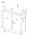
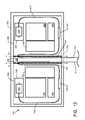
- FIG. 2is a front perspective view of an example telecommunications cabinet having a cabinet housing with front doors shown in a closed position;
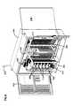
- FIG. 3is a front, perspective view of the cabinet of FIG. 2 with the front and rear doors in an open position;
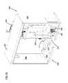
- FIG. 4is a rear, perspective view of the cabinet of FIG. 2 with the rear doors removed;
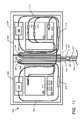
- FIG. 5is a schematic block diagram showing a first swing frame and a second swing frame pivotably mounted within the cabinet of FIG. 2 ;
- FIG. 6is a front view of the cabinet of FIG. 2 with the front doors in the open position and the first and second swing frames visible through an open front;
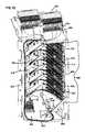
- FIG. 7is a front, perspective view of the cabinet of FIG. 2 with the front doors removed to reveal the front of the first and second swing frames;
- FIG. 8is a front, perspective view of the cabinet of FIG. 2 with the rear doors removed, the first swing frame pivoted within the cabinet interior, and the second swing frame pivoted out of the cabinet interior;
- FIG. 9is a front, perspective view of the cabinet of FIG. 2 with the first swing frame pivoted out of the cabinet interior and the second swing frame pivoted within the cabinet interior;
- FIG. 10is a rear, perspective view of the cabinet of FIG. 8 ;
- FIG. 11is a schematic diagram of first and second cable routing paths according to one embodiment of the present disclosure.
- FIG. 12is a schematic diagram of a first segment of each of the cable routing paths of FIG. 11 ;
- FIG. 13is a schematic diagram of a second segment of each of the cable routing paths of FIG. 11 ;
- FIG. 14is a schematic diagram of a third segment of each of the cable routing paths of FIG. 11 ;
- FIG. 15is a left, rear perspective view of the first swing frame removed from the cabinet housing and being pre-cabled with stub cables;
- FIG. 16is a right, rear perspective view of the second swing frame removed from the cabinet housing and being pre-cabled with stub cables;
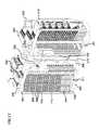
- FIG. 17is a front, perspective view of the first and second swing frames removed from the cabinet housing, splitter pigtails being routed over the front of the swing frames along the second segment of the routing cable paths of FIGS. 11 and 13 ;
- FIG. 18is a rear view of the cabinet of FIG. 3 with the rear doors removed to reveal the rear sides of the first and second swing frames and stub cables precabled from a mounting bulkhead to termination modules on each swing frame;
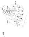
- FIG. 19is a right, rear perspective view of the first swing frame removed from the cabinet housing and being cabled with pass-through fibers;
- FIG. 20is a left, rear perspective view of the second swing frame removed from the cabinet housing and being cabled with pass-through fibers;
- FIG. 21is a partial, rear perspective view of the cable access region and rear lip of the cabinet housing of FIG. 3 with the rear doors removed;
- FIG. 22is a partial, rear perspective view of a panel arrangement covering the cable access region and an access panel covering a portion of the lip of FIG. 21 ;
- FIG. 23is a top view of the panel arrangement of FIG. 22 removed from the cabinet housing;
- FIG. 24is a top view of the panel arrangement of FIG. 23 installed on the bottom panel of the cabinet housing of FIG. 21 ;
- FIG. 25is an operational flow for a process for replacing the cabinet housing without disturbing the internal components of the cabinet housing.
- the cabinet 200provides an interconnect interface for optical transmission signals at a location in the network where operational access and reconfiguration are desired.
- Embodiments of the cabinet 200can provide termination, splicing, interconnection, splitting, and combinations thereof.
- a connectionbetween fibers includes both direct and indirect connections.
- a cabinet 200typically administers connections between fiber optic cables and passive optical splitters in an Outside Plant (OSP) environment (see FIG. 1 ).
- OSPOutside Plant
- a cabinet 200can be used to splice or otherwise connect one or more feeder cables, split the feeder cables, and terminate the split feeder cables to subscriber cables.
- the cabinet 200is designed to accommodate a range of alternative sizes and fiber counts and support factory installation of pigtails, fanouts and splitters.
- one example telecommunications cabinet 200includes a cabinet housing 201 that houses internal components, as described further below.
- the cabinet housing 201has a length L extending from a first side panel 206 to a second side panel 208 ( FIG. 4 ), a width W extending from an open front 203 ( FIG. 3 ), to an open rear 205 ( FIG. 4 ), and a height H extending from a top panel 202 to a bottom panel 204 ( FIG. 4 ).
- the top, bottom and side panels 202 , 204 , 206 , 208define a cabinet interior accessible through the open front 203 ( FIG. 3 ), and through the open rear 205 ( FIG. 4 ) of the cabinet housing 201 .
- a first front door 212 and a second front door 214mount to the front 203 of the cabinet housing 201 .
- the front doors 212 , 214pivot from a closed position, in which the doors 212 , 214 cover the open front 203 (see FIG. 2 ), to an open position to facilitate access through the open front 203 to the internal components mounted within cabinet housing 201 .
- the front doors 212 , 214include a lock 211 .
- first and second rear doors 216 , 218pivotably mount to the rear of the cabinet housing 201 ( FIG. 3 ).
- the rear doors 216 , 218pivot to a closed position to cover the open rear 205 and to an open position (see FIG. 3 ) to facilitate access to the internal components of the cabinet 200 through the open rear 205 .
- the open rear side of the cabinetcan be enclosed by a rear panel.
- the cabinet housing 201typically houses a mounting post 220 (also see FIG. 6 ) extending from the top panel 202 to the bottom panel 204 at the front 203 of the cabinet housing 201 .
- the mounting post 220has a width W MP ( FIG. 5 ).
- W MPFIG. 5
- the mounting post 220is positioned at approximately equal distances from the first and second side panels 206 , 208 .
- the mounting post 220is removably coupled to the cabinet housing 201 .
- the cabinet housing 201also includes a cable access region 210 ( FIG. 4 ) defining an opening through which cables can enter and exit the interior of the cabinet housing 201 .
- the cable access region 210is defined in the bottom panel 204 at the rear 205 of the cabinet housing 201 .
- the cable access region 210can also be provided in a rear panel (not shown) or in one of the side panels 206 , 208 .
- a mounting bulkhead 225extends rearwardly within the cabinet interior from the mounting post 220 to the open rear 205 .
- the mounting bulkhead 225generally extends over the cable access region 210 .
- Cable management devicessuch as cable clamps 227 ( FIG. 22 ), are provided on at least one side of the mounting bulkhead 225 .
- the cable management devices 227are provided on both sides 222 , 224 of the mounting bulkhead 225 .
- Telecommunications cablese.g., feeder cables and subscriber cables
- the cabinet housing 201is typically manufactured from heavy gauge aluminum and is NEMA-4X rated.
- the cabinet housing 201is configured to provide protection against rain, wind, dust, rodents and other environmental contaminants.
- the cabinet housing 201remains relatively lightweight for easy installation, and breathable to prevent accumulation of moisture in the unit.
- An aluminum construction with a heavy powder coat finishalso provides for corrosion resistance. Other materials can be used without limitation.
- Different sizes of the cabinet 200are typically available to correspond to different subscriber cable fiber counts including, for example, 144, 216, and 432. Alternative sizes for the cabinet 200 can be used without limitation. Additional details regarding example telecommunication cabinet housings similar to cabinet housing 201 can be found in U.S. patent application Ser. No. 11/203,157 filed on Aug. 15, 2005, the entirety of which is hereby incorporated by reference.
- the mounting bulkhead 225generally divides the interior into a first portion 222 and a second portion 224 .
- a first swing frame 300is pivotably mounted to a first side 226 of the mounting post 220 within the first portion 222 of the cabinet interior ( FIG. 5 ).
- a second swing frame 300 ′is pivotably mounted to a second, opposite side 228 of the mounting post 220 within the second portion 224 of the cabinet interior ( FIG. 5 ).
- hinges 314couple front sides of the swing frames 300 , 300 ′ to the mounting post 220 .
- a first termination region 350 and a second termination region 350 ′are provided on the first and second swing frames 300 , 300 ′, respectively ( FIGS. 5 and 6 ).
- Each of the swing frames 300 , 300 ′also includes a splitter region 320 , 320 ′, a cable management region 330 , 330 ′, and a storage region 340 , 340 ′, respectively.
- the splitter regions 320 , 320 ′are located above the termination regions 350 , 350 ′ and the storage regions 340 , 340 ′ are located beneath the termination regions 350 , 350 ′ ( FIG. 5 ).
- Each swing frame 300 , 300 ′also can include a cable interface region 310 , 310 ′ ( FIG. 11 ) in the rear of the swing frame 300 , 300 ′. In other embodiments, however, one or more of these regions can be located within the cabinet housing 201 , but not on either of the swing frames 300 , 300 ′.
- the first swing frame 300is configured to pivot about a first pivot axis A P , which extends generally parallel to the mounting post 220 ( FIG. 5 ).
- the second swing frame 300 ′is configured to pivot about a second pivot axis A P ′, which extends generally parallel to the mounting post 220 and is spaced from the first pivot axis A P approximately by the width W MP of the mounting post 220 ( FIG. 5 ).
- both pivot axes A P , A P ′are located adjacent the front 203 of the cabinet housing 201 ( FIG. 7 ).
- each swing frame 300 , 300 ′is configured to pivot out of the cabinet interior through the open front 203 .
- the swing frame 300can be pivoted approximately ninety degrees or more out of the cabinet 201 .
- the swing frames 300 , 300 ′can include latches or other structures 311 ( FIG. 17 ) to selectively lock the swing frame into a first, “swung in” position and into a second, “swung out” position.
- Pivoting the swing frames 300 , 300 ′ out of the cabinet housing 201facilitates access to components installed on the swing frames 300 , 300 ′ for cleaning, testing, maintenance, additions, etc.
- pivoting the second swing frame 300 ′ into an open positionfacilitates access to a rear side of the termination region 350 ′, the splitter region 320 ′, and the cable interface region 310 ′.
- pivoting the swing frames 300 , 300 ′ into the open positionalso facilitates access to the cable access region 210 and the mounting bulkhead 225 through the open rear 205 of the cabinet housing 201 .
- FIG. 11shows one example cable routing scheme by which incoming fibers can be optically coupled to outgoing fibers.
- incoming fibersinclude the fibers of feeder cables 410 that enter the cabinet housing 201 and intermediate fibers (e.g., connectorized pigtails 420 extending from splitters and patching fibers/jumpers) that connect the feeder cable fibers to the termination regions 350 , 350 ′.
- intermediate fiberse.g., connectorized pigtails 420 extending from splitters and patching fibers/jumpers
- outgoing fibersinclude the fibers of subscriber cables 440 and the fibers of stub cables 430 that connect the subscriber cable fibers to the termination regions 350 , 350 ′.
- the cable routing scheme of FIG. 11includes a first cable routing path and a second cable routing path.
- the first cable routing pathdirects optical fibers from the cable access region 210 to the termination region 350 on the first swing frame 300 and back to the cable access region 210 .
- the second cable routing pathdirects optical fibers from the cable access region 210 to the termination region 350 ′ on the second swing frame 300 ′ and back to the cable access region 210 .
- the first cable routing pathmirrors the second cable routing path.
- the first and second cable routing pathsinclude three main segments.
- the first segmentis shown in FIG. 12 ; the second segment is shown in FIG. 13 ; and the third segment is shown in FIG. 14 .
- feeder cable fibersare initially routed into the cabinet housing 201 through the cable access region 210 .
- the fibers of the feeder cables 410can include ribbon fibers.
- An example feeder cable 410may include twelve to forty-eight individual fibers connected to a service provider central office 101 ( FIG. 1 ).
- the fibers of the feeder cablecan be routed to one or both swing frames 300 , 300 ′ along the cable routing paths.
- the fibers of a feeder cable 410are routed along the first segment of the cable routing path.
- the feeder cable 410is routed up one of the sides 222 , 224 of the mounting bulkhead 225 , down a rear side of one or both of the swing frames 300 , 300 ′ adjacent the mounting bulkhead 225 , and then back up the swing frame 300 , 300 ′ to the splitter region 320 , 320 ′ (see also FIG. 18 ).
- the fibers of a first feeder cable 410are routed to a first feeder cable interface 310 (e.g., a fiber optic adapter module, a splice tray, etc.) installed on the first swing frame 300 .
- a first feeder cable interface 310e.g., a fiber optic adapter module, a splice tray, etc.
- the fibers of the feeder cable 410are individually connected to separate splitter input fibers 415 that are routed to the first splitter region 320 .
- the fibers of the feeder cable 410can be routed directly to the first splitter region 320 , thereby bypassing or eliminating the need for an intermediate feeder cable interface 310 .
- the splitter input fibers 415(or the fibers of the feeder cables 410 ) are connected to separate splitters 500 at which each of the fibers can be split into multiple pigtails 420 ( FIG. 13 ).
- Each pigtail 420has a connectorized end 425 .
- the pigtails 420generally extend along the second segment of the cable routing path from the splitter region 320 to the cable management regions 330 ( FIG. 13 ).
- the connectorized ends 425can be temporarily stored on one or more storage receptacles 610 ( FIG. 13 ) mounted at the storage regions 340 .
- the pigtails 420are needed for service, the pigtails 420 are routed along the second segment of the first cable routing path from the splitters 500 to termination adapters 710 ( FIG. 13 ) provided at the termination regions 350 .
- pigtails 420 extending from the splitter region 320 on the first swing frame 300can be routed along the cable management panel 330 to the first termination region 350 . In other embodiments, however, the pigtails 420 can be routed from the splitter region 320 on the first swing frame 300 to the termination region 350 ′ on the second swing frame 300 ′ ( FIGS. 13 and 17 ). In such embodiments, the pigtails 420 are typically routed down along the cable management region 330 of the first swing frame 300 . The pigtails 420 are then routed past the mounting post 220 to the second swing frame 300 ′ and up the cable management region 330 ′ of the second swing frame 300 ′ to the second termination region 350 ′ (see FIGS. 13 and 17 ).
- one or more fibers of the feeder cable 410are not connected to any of the splitters 500 , but rather are connected through the interface device 310 to pass-through fibers 412 (see FIGS. 19 and 20 ), which are routed past the splitter region to connect to the termination region 350 .
- pass-through fibers 412By refraining from splitting a fiber of a feeder cable 410 , a stronger signal can be sent to one of the subscribers 105 ( FIG. 1 ).
- the connectorized ends of the pass-through fibers 412can be stored at the storage region 340 when not in use.
- a feeder cable 410 having a connectorized endcan be routed directly to the termination region 350 .
- the connectorized pigtails 420are connected to the connectorized fibers of stub cables 430 or to intermediary cables (not shown) optically coupled to the stub cables 430 .
- the stub cables 430are directed along the third segment of the cable routing path back to the cable access region 210 and out of the cabinet housing 201 (see FIG. 14 ).
- the stub cables 430are routed down the rear side of the termination region, up the rear side of the cable management panel 330 , and down one side of the mounting bulkhead 225 to the cable access region 210 ( FIG. 18 ).
- the stub cables 430are optically coupled to subscriber cables 440 at a coupling location 280 ( FIG. 14 ).
- the coupling location 280is housed within a generally hollow base 240 on which the cabinet housing 201 is mounted ( FIGS. 2 and 3 ).
- the base 240defines at least one access panel (not shown) through which the interior of the base 240 and, hence, the coupling location 280 , can be accessed to optically couple the stub cables 430 , 430 ′ to the subscriber distribution cables 440 .
- the stub cables 430range in length from about 25 feet to about 300 feet.
- a typical subscriber cable 440forms the F 2 portion of a network (see FIG. 1 ) and typically includes a plurality of fibers (e.g., 144, 216 or 432 fibers) that are routed from the cabinets 200 to the subscriber locations 105 ( FIG. 1 ).
- the termination regions 350 , 350 ′therefore, are the dividing line between incoming fibers and the outgoing fibers.
- the subscriber cables 440can be routed directly into the cabinet housing 201 . These subscriber cables 440 are connected either to the termination regions 350 , 350 ′ or to intermediary fibers (not shown).
- the above described cable routing schemein combination with the placement of the pivot axes A P , A P ′ of the swing frames 300 , 300 ′ provides excess fiber length along the points of flex for fibers routed within the cabinet 200 .
- Each segment of the cable routing pathroutes fibers along a path parallel to and adjacent the axes Ap, Ap 1 . Routing the fibers up and down the cabinet interior adjacent the mounting post 220 inhibits twisting, bending, or kinking of the fibers when the swing frames 300 , 300 ′ are pivoted between the “swung in” and “swung out” positions.
- the fiberscan distribute any rotational movement caused by pivoting the swing frames 300 , 300 ′ along the length of the fibers.
- the termination regions 350 , 350 ′can be fully loaded with adapters and pre-terminated in the factory with 435 , 435 ′ stub cables 430 , 430 ′ (see FIGS. 15 , 16 , and 18 ).
- the stub cable fibers 430 , 430 ′are coupled to the termination regions 350 , 350 ′ (e.g., inserted into the rear sides of termination adapters 710 installed at the termination region 350 , 350 ′) ( FIGS. 15 and 16 ).
- Preconfiguring the cabinet 200reduces the chance that cabling will be done incorrectly.
- Some of the fibers of the feeder cable 410can be protected within the cabinet housing 201 by loose buffer tubes. Fan-out blocks can be provided at suitable locations within the cabinet housing 201 to separate and join ribbon fibers. Spools, clips, holders, brackets or other cable management structures can also be provided within the cabinet housing 201 to facilitate managing the fibers of cables 410 , 420 , 430 , 440 routed within of the cabinet housing 201 .
- each of the componentscould be mounted elsewhere within the cabinet housing 201 .
- the swing frame 300includes a primary bulkhead 301 extending between a top panel 302 and a bottom panel 304 ( FIG. 15 ).
- the splitter region 320is provided on the top panel 302 and the cable interface region 310 is provided on the bottom panel 304 .
- the storage region 340is provided on the front of the primary bulkhead 301 ( FIG. 17 ) and the termination region 350 extends through a portion of the primary bulkhead 301 from the front to the rear ( FIGS. 19-20 ).
- Cable management devices 309such as bend limiters and clips, can be provided on the rear of the primary bulkhead 301 opposite the storage region 340 ( FIGS. 15 and 16 ).
- a secondary bulkhead 303also extends between the top and bottom panels 302 , 304 .
- Cable management devices 308can be provided on the rear of the secondary bulkhead 303 ( FIGS. 19 and 20 ).
- One edge of the secondary bulkhead 303couples to the primary panel 301 ( FIG. 17 ).
- the opposite edge of the secondary bulkhead 303couples to a hinge-mounting panel 305 ( FIGS. 19 and 20 ).
- Hinges 314 or other fastenerspivotably couple the hinge-mounting panel 305 to the mounting post 220 ( FIG. 3 ).
- the cable management region 330is provided on the front of the secondary bulkhead 303 ( FIG. 17 ).
- the cable management region 330includes a ramp 332 extending downwardly from the top panel 302 to the front side of the secondary bulkhead 303 (see FIG. 6 ).
- the cablescan be routed through the radius limiters 334 , 336 ( FIG. 6 ) or other cable management structures provided on the front of the secondary bulkhead 303 either to the storage region 340 or to the termination region 350 on either of the swing frames 300 , 300 ′.
- the ramp 303is typically provided within close proximity of the mounting post 220 to provide a sufficient length of splitter fiber 420 adjacent the pivot axes A P , A P ′ to inhibit kinking the fiber 420 as discussed above ( FIG. 6 ).
- the splitter region 320includes a splitter module housing 322 provided on the top panel 302 .
- the splitter module housing 322is configured to protect, organize, and secure the splitters 500 .
- the splitter module housing 322can be constructed in various sizes to accommodate different numbers of splitter modules 500 .
- the module housing 322is further configured to enable the splitters 500 to receive an input fiber, such as splitter input fiber 415 ( FIG. 11 ), on one end of the splitter 500 and to output multiple fibers, such as splitter pigtails 420 ( FIG. 11 ), from the opposing end of the splitter 500 .
- each splitter 500receives between one and four fibers 415 and outputs between two and sixteen fibers 420 for every input fiber 415 .
- four input fibers 415enter a splitter 500 and thirty-two pigtail fibers 420 exit the splitter 500 .
- Further information regarding example splitters 500can be found in U.S. patent application Ser. No. 11/354,297, filed Feb. 13, 2006, entitled “Fiber Optic Splitter Module;” U.S. application Ser. No. 10/980,978, filed Nov. 3, 2004, entitled “Fiber Optic Module And System Including Rear Connectors;” U.S. application Ser. No. 11/138,063, filed May 25, 2005, entitled “Fiber Optic Splitter Module;” U.S.
- the swing frame 300can be configured with different interface devices 310 (see FIG. 11 ) to receive incoming feeder cables 410 .
- Information regarding one example type of interface device, an adapter packcan be found in U.S. application Ser. No. 11/095,033, filed Mar. 31, 2005, and entitled “Adapter Block Including Connector Storage;” and U.S. Pat. Nos. 5,497,444; 5,717,810; 5,758,003; and 6,591,051, the disclosures of which are hereby incorporated by reference. Any other suitable type of interface device, such as a splice tray, can also be used.
- Splitter input cables 415 ( FIGS. 15 and 16 ) or pass-through cables 412 ( FIGS. 19 and 20 )are routed from the interface devices 310 , up the swing frame 300 through cable management structures 316 , and to the splitter region 320 on the top panel 302 ( FIGS. 15 and 16 ).
- the storage region 340also defines one or more openings 342 into which storage modules 610 (see FIG. 11 ) can be mounted.
- the connectorized pigtails 420 of the splitters 500are typically stored in one or more of the storage modules 610 prior to installation on the swing frame 300 , thereby enabling the splitters 500 and storage modules 610 to be added incrementally to the swing frame 300 . Additional information regarding the storage modules 610 can be found in U.S. application Ser. No. 10/610,325, filed on Jun. 30, 2003, entitled “Fiber Optic Connector Holder and Method; “U.S. application Ser. No. 10/613,764, filed on Jul. 2, 2003, entitled “Telecommunications Connection Cabinet;” and U.S. application Ser. No. 10/871,555, filed on Jun. 18, 2004, entitled “Multi-position Fiber Optic Connector Holder and Method,” the disclosures of which are hereby incorporated by reference.
- the termination region 350generally includes multiple termination adapters 710 configured to receive and optically couple two terminated optical fibers.
- the termination adapters 710extend from a front to a rear of the primary bulkhead 301 .
- the primary bulkhead 301defines one or more columns of openings 352 ( FIG. 7 ) through which the adapters 710 extend.
- Strips 359FIG. 17 ) separate the openings 352 of each column and provide surface area for adhering labeling information (e.g., connector designation).
- the termination adapters 710are mounted to one or more termination modules 700 which can mount to the primary bulkhead 301 .
- Each termination module 700includes at least one row of termination adapters 710 for connecting the fibers of the feeder cable 410 to the fibers of the subscriber cable 440 .
- Each adapter 710has a front end 712 ( FIG. 17 ) and a rear end 714 ( FIG. 15 ).
- the front end 712 of each adapter 710is configured to retain a connector 425 of a fiber 420 interfaced with the feeder cable 410 .
- the rear end 714 of each adapter 710is configured to retain a connector 435 of a fiber interfaced with the subscriber cable 440 (or stub cable 430 ).
- a front side of the termination leg 702 of the termination module 700mounts to the rear side of the primary bulkhead 301 , for example, using screws or other temporary or permanent fasteners such as bolts, and rivets.
- the management leg 704extends generally rearwardly from an inner side (i.e., the side nearest the mounting post 220 ) of the termination leg 702 ( FIGS. 15 and 16 ). Typically, the management leg 704 extends rearwardly from where the primary bulkhead 301 couples to the secondary bulkhead 303 (see FIGS. 19 and 20 ).
- the management legs 704 of the termination modules 700can be secured to one another or to the swing frame 300 as shown in FIGS. 15 , 16 , 19 , and 20 .
- the termination leg 702defines openings in which the adapters 710 can be installed.
- the adapters 710typically extend from the termination leg 702 and through the openings 352 ( FIG. 19 ) defined in the primary bulkhead 301 so that the connectors 425 enter the front ends 712 of the adapters 710 from a front side of the primary bulkhead 301 and the connectors 435 of the subscriber cable 440 enter the adapters 710 from a rear side of the primary bulkhead 301 .
- Each management leg 704includes an appropriate number of fanouts 707 ( FIGS. 19 and 20 ) to accommodate the adapters 710 on the termination module 700 .
- the termination leg 702 of a module 700includes six rows of adapters 710 , each row having twelve adapters 710
- the management leg 704includes six 12:1 fanouts 707 .
- a 12:1 fanoutis a fanout configured to receive twelve optical fibers and to output a single cable ribbon containing the twelve fibers.
- nine 8:1 fanouts or three 24:1 fanoutscould be provided instead of the 12:1 fanouts.
- the fanouts 707can be used to upjacket the fiber.
- the management leg 704 of the termination module 700also includes at least one cable management device 713 ( FIG. 9 ) for managing excess fiber length of the stub cable fibers 430 .
- the fibers 430are typically routed first to the cable management device 713 and then to the fanouts 707 .
- Examples of cable management devices 713include one or more radius bend limiters, one or more fiber clips, and other such devices.
- the management leg 704 of the termination module 700typically defines an opening 708 ( FIGS. 19 and 20 ) through which the stub cable fibers 430 are routed from the cable management devices 713 to the fanouts 707 .
- the ribbon fibersUpon exiting the fanouts 707 , the ribbon fibers are routed towards the bottom panel 304 through the cable management structures 308 provided on the rear side of the secondary bulkhead 303 ( FIG. 18 ). The ribbon fibers are then routed back up towards the top panel 302 through the cable management structures 307 provided on the hinge-mounting panel 305 and down a side 222 , 224 of the mounting bulkhead 225 to the cable access region 210 (see FIG. 18 ).
- the termination modules 700can be precabled at the factory to include connectorized fibers of a stub cable 430 coupled to each adapter 710 .
- the connector 435 of each stub cable fiberis mounted within the rear end 714 of an adapter 710 and the stub cable fibers are routed from the connector 710 to the fanouts 707 provided on the management leg 704 of the termination module 700 .
- dust capscan be provided on the front ends 712 of the adapters 710 to protect the terminated stub fibers 430 from dust, dirt, and other contaminants.
- the cabinet housing 201can be replaced without disrupting the internal components of the cabinet 200 .
- This “reskinnable” featureis advantageous if the cabinet housing 201 ever becomes damaged (e.g., if the cabinet housing 201 sustains structural damage due to a collision with an automobile).
- the cabinet housing 201is designed to be separable from the mounting post 220 , the mounting bulkhead 225 , and the swing frames 300 , 300 ′.
- the cabinet housing 201is configured to be replaced without removing the feeder cables 410 and stub cables 430 from the mounting bulkhead 225 ( FIG. 21 ).
- a panel arrangement 250( FIG. 23 ) is provided over the cable access region 210 to protect the internal components of the cabinet 200 from environmental contamination (see FIG. 22 ).
- the panel arrangement 250is removably coupled to the cabinet housing 201 to cover the opening defined in the cable access region 210 .
- the panel arrangement 250typically includes multiple pieces that cooperate to form one or more apertures 258 through which cables (e.g., feeder cables 410 and stub cables 430 ) can extend (see FIG. 22 ).
- the example panel arrangement 250includes an intermediate panel 254 , a first end panel 252 arranged on one side of the intermediate panel 254 , and a second end panel 256 arranged on an opposite side of the intermediate panel 254 .
- the inside edge of each of the end panels 252 , 256forms one or more concave detents 259 .
- the outer edges of the intermediate panel 254also form one or more concave detents 259 .
- the concave detents 259 on the first end panel 252cooperate with the concave detents 259 on the intermediate panel 254 to form a first set of openings 258 through which the cables 410 , 430 can extend.
- the concave detents 259 on the second end panel 252also cooperate with the concave detents 259 on the intermediate panel 254 to form a second set of openings 258 through which the cables 410 , 430 can extend.
- the first and second end panels 252 , 256each have a fastening section 253 extending along the outer edge, opposite the intermediate panel 254 .
- Each fastening sectionincludes one or more apertures 251 through which fasteners may be inserted.
- the intermediate panel 254has at least one fastening section 257 extending outwardly from the intermediate panel 254 towards the open front 203 of the cabinet housing 201 .
- the fastening section 257includes first and second protruding tabs defining apertures 251 .
- the intermediate panel 254also includes a flange 255 extending towards the open rear 205 of the cabinet. Apertures can also be provided on the flange 255 .
- the panels 252 , 254 , 256can each be installed over the cable access region 210 by inserting fasteners through the apertures 251 in the fastening sections 253 ( FIG. 22 ).
- a lip 260extends upwardly from the rearward edge of the bottom panel 204 of the cabinet housing 201 .
- the lip 260inhibits optical fibers from spilling out from the cabinet interior.
- the lip 260is L-shaped.
- the lip 260is interrupted (e.g., defines an opening or space) at a central portion 264 of the lip 260 .
- the opening defined by the lip 260is continuous with the opening defined by the cable access region 210 (see FIG. 4 ).
- the length L L of the interruptiongenerally matches a length L A of the cable access region 210 .
- a lip access panel 265can be removably coupled to the lip 260 to cover the interruption in the lip 260 (see FIGS. 21 and 22 ). As shown in FIG. 22 , one embodiment of the access panel 265 can extend over an outer and bottom portion of the lip 260 . Removing the access panel 265 and the panel arrangement 250 reveals the continuous opening defined by the cable access region 210 and the central portion 264 of the lip 260 (see FIG. 4 ).
- FIG. 24illustrates a top view of the panel arrangement 250 installed over the bottom panel 204 of the cabinet housing 201 .
- the panel arrangementis also coupled to a mounting post bracket 270 .
- the mounting post bracket 270includes a first U-shaped member 272 and a second U-shaped member 274 spaced from the first member 272 to define an aperture 275 .
- a first fastening side 276extends from one side of both the first member 272 and the second member 274 .
- Second and third fastening sides 273 , 277extend from the opposite side of the first member 272 and second member 274 , respectively.
- the mounting post bracket 270is secured to the bottom panel 204 of the cabinet housing 201 .
- the mounting post bracket 270is arranged to receive the bottom end of the mounting post 220 within the aperture 275 .
- the mounting post bracket 270is further configured to facilitate releasing the mounting post 220 from the mounting post bracket 270 .
- the intermediate panel 254can also be removably secured to the mounting post bracket 270 .
- the protruding tabs 257can couple to the first and second members 272 , 274 as shown in FIG. 24 .
- FIG. 25illustrates an operational flow for an example process for replacing the housing 201 of a telecommunications cabinet 200 .
- the process 2400begins at start module 2402 and proceeds to a first remove operation 2404 .
- the first remove operation 2404removes the access panel 265 from the lip 260 on the cabinet housing 201 to reveal the opening in the lip 260 .
- a second remove operation 2406removes the panels 252 , 254 , 256 of the panel arrangement 250 from the cabinet housing 201 to expose the opening defined by the cable access region 210 .
- a third remove operation 2408removes any grounding wires 268 extending between the cables coupled to the mounting bulkhead 225 and the cabinet housing 201 (see FIG. 21 ).
- a fourth remove operation 2410uncouples the mounting post 220 and mounting bulkhead 225 from the cabinet housing 201 .
- the remove operation 2410can disengage the mounting post 220 from the mounting bracket 270 .
- a stabilize operation 2412props or otherwise maintains the internal components of the cabinet 200 in an upright or otherwise safe position while disengaged from the cabinet housing 201 .
- a fifth remove operation 2414slides (or otherwise moves) the cabinet housing 201 away from the internal components.
- the fifth remove operation 2414can slide the cabinet housing 201 forwardly of the base 240 until the internal components have passed through the open rear 205 and cleared the housing 201 .
- a replace operation 2418installs a new cabinet housing around the internal components.
- the new cabinet housingalso includes a continuous opening defined by a cable access region and an interrupted lip through which the cables can pass when the new housing is being installed.
- the mounting post 220is secured to the new cabinet housing.
- the process 2400ends at stop module 2418 .
- the fiber distribution hub 200can be manufactured in a variety of different sizes. However, to promote manufacturing efficiency, it is preferred for the splitters to be manufactured with pigtails having uniform lengths. To accommodate the different sizes of fiber distribution hubs, the pigtails are preferably designed long enough to work in the largest fiber distribution hub expected to be used. For the smaller distribution hubs, excess length provided in the pigtails can be taken up by routing the excess length through various cable management structures.
Landscapes
- Physics & Mathematics (AREA)
- Engineering & Computer Science (AREA)
- Computer Networks & Wireless Communication (AREA)
- General Physics & Mathematics (AREA)
- Optics & Photonics (AREA)
- Light Guides In General And Applications Therefor (AREA)
- Structure Of Telephone Exchanges (AREA)
Abstract
Description
Claims (15)
Priority Applications (1)
| Application Number | Priority Date | Filing Date | Title |
|---|---|---|---|
| US13/114,525US8357851B2 (en) | 2006-10-02 | 2011-05-24 | Fiber distribution hub with dual swing frames |
Applications Claiming Priority (4)
| Application Number | Priority Date | Filing Date | Title |
|---|---|---|---|
| US84890206P | 2006-10-02 | 2006-10-02 | |
| US11/864,182US7728225B2 (en) | 2006-10-02 | 2007-09-28 | Fiber distribution hub with dual swing frames |
| US12/770,190US7964793B2 (en) | 2006-10-02 | 2010-04-29 | Fiber distribution hub with dual swing frames |
| US13/114,525US8357851B2 (en) | 2006-10-02 | 2011-05-24 | Fiber distribution hub with dual swing frames |
Related Parent Applications (1)
| Application Number | Title | Priority Date | Filing Date |
|---|---|---|---|
| US12/770,190ContinuationUS7964793B2 (en) | 2006-10-02 | 2010-04-29 | Fiber distribution hub with dual swing frames |
Publications (2)
| Publication Number | Publication Date |
|---|---|
| US20110285265A1 US20110285265A1 (en) | 2011-11-24 |
| US8357851B2true US8357851B2 (en) | 2013-01-22 |
Family
ID=39185314
Family Applications (6)
| Application Number | Title | Priority Date | Filing Date |
|---|---|---|---|
| US11/796,805Expired - Fee RelatedUS7711234B2 (en) | 2006-10-02 | 2007-04-30 | Reskinnable fiber distribution hub |
| US11/864,182Expired - Fee RelatedUS7728225B2 (en) | 2006-10-02 | 2007-09-28 | Fiber distribution hub with dual swing frames |
| US12/752,677Expired - Fee RelatedUS8009955B2 (en) | 2006-10-02 | 2010-04-01 | Reskinnable fiber distribution hub |
| US12/770,190ActiveUS7964793B2 (en) | 2006-10-02 | 2010-04-29 | Fiber distribution hub with dual swing frames |
| US13/114,525Active2027-11-10US8357851B2 (en) | 2006-10-02 | 2011-05-24 | Fiber distribution hub with dual swing frames |
| US13/187,016AbandonedUS20110277292A1 (en) | 2006-10-02 | 2011-07-20 | Reskinnable fiber distribution hub |
Family Applications Before (4)
| Application Number | Title | Priority Date | Filing Date |
|---|---|---|---|
| US11/796,805Expired - Fee RelatedUS7711234B2 (en) | 2006-10-02 | 2007-04-30 | Reskinnable fiber distribution hub |
| US11/864,182Expired - Fee RelatedUS7728225B2 (en) | 2006-10-02 | 2007-09-28 | Fiber distribution hub with dual swing frames |
| US12/752,677Expired - Fee RelatedUS8009955B2 (en) | 2006-10-02 | 2010-04-01 | Reskinnable fiber distribution hub |
| US12/770,190ActiveUS7964793B2 (en) | 2006-10-02 | 2010-04-29 | Fiber distribution hub with dual swing frames |
Family Applications After (1)
| Application Number | Title | Priority Date | Filing Date |
|---|---|---|---|
| US13/187,016AbandonedUS20110277292A1 (en) | 2006-10-02 | 2011-07-20 | Reskinnable fiber distribution hub |
Country Status (3)
| Country | Link |
|---|---|
| US (6) | US7711234B2 (en) |
| EP (1) | EP2074460A2 (en) |
| WO (1) | WO2008042357A2 (en) |
Cited By (1)
| Publication number | Priority date | Publication date | Assignee | Title |
|---|---|---|---|---|
| US12298581B2 (en) | 2020-01-29 | 2025-05-13 | Afl Telecommunications Llc | Terminal enclosure for a telecommunications system |
Families Citing this family (62)
| Publication number | Priority date | Publication date | Assignee | Title |
|---|---|---|---|---|
| US8228926B2 (en)* | 2005-04-12 | 2012-07-24 | Genband Us Llc | Dynamic loading for signaling variants |
| US7711234B2 (en) | 2006-10-02 | 2010-05-04 | Adc Telecommunications, Inc. | Reskinnable fiber distribution hub |
| US7349616B1 (en) | 2007-01-12 | 2008-03-25 | Corning Cable Systems Llc | Fiber optic local convergence points for multiple dwelling units |
| US7522805B2 (en)* | 2007-03-09 | 2009-04-21 | Adc Telecommunications, Inc. | Wall mount distribution arrangement |
| DE102007012079B4 (en)* | 2007-03-13 | 2011-07-14 | ADC GmbH, 14167 | Distribution cabinet with several inner housings |
| US8385709B2 (en)* | 2007-06-01 | 2013-02-26 | Telect Inc. | Structured cabling solutions |
| US7720344B2 (en)* | 2007-10-22 | 2010-05-18 | Adc Telecommunications, Inc. | Fiber distribution hub |
| US8229265B2 (en) | 2007-11-21 | 2012-07-24 | Adc Telecommunications, Inc. | Fiber distribution hub with multiple configurations |
| US8238709B2 (en) | 2007-12-18 | 2012-08-07 | Adc Telecommunications, Inc. | Multi-configuration mounting system for fiber distribution hub |
| DE102008012460C5 (en)* | 2008-03-04 | 2013-04-25 | Berthold Sichert Gmbh | Base plate or cable distribution cabinet with a base plate and mounting method |
| JP5134428B2 (en)* | 2008-05-07 | 2013-01-30 | ヤンマー株式会社 | Arrangement structure of control box and power converter in package storage type engine generator |
| US8606067B2 (en)* | 2009-09-04 | 2013-12-10 | Adc Telecommunications, Inc. | Pedestal terminal with swing frame |
| US8428419B2 (en)* | 2009-09-23 | 2013-04-23 | Adc Telecommunications, Inc. | Fiber distribution hub with internal cable spool |
| CA2680941A1 (en)* | 2009-09-29 | 2011-03-29 | Custom Diamond International Inc. | Method and kit to replace an instrument case |
| US20110116239A1 (en)* | 2009-11-17 | 2011-05-19 | Emerson Network Power, Energy Systems, North America, Inc. | Locking Mechanisms for Retaining Two Swinging Panels and Apparatus and Enclosures Including a Locking Mechanism for Retaining Two Swinging Panels |
| CN102792203B (en)* | 2010-02-15 | 2016-08-03 | 泰科电子瑞侃有限公司 | For distributor box, in particular for the cable supporting member of FTTH environment |
| WO2011140461A2 (en)* | 2010-05-07 | 2011-11-10 | Adc Telecommunications, Inc. | Fiber distribution hub with pass-through interfaces |
| PL3594729T3 (en)* | 2010-06-23 | 2021-11-22 | Corning Research & Development Corporation | Fiber optic cabinet and cabinet lift |
| KR101212889B1 (en)* | 2010-10-01 | 2012-12-14 | 하이디스 테크놀로지 주식회사 | Cassette for loading Glasses |
| WO2012054454A2 (en) | 2010-10-19 | 2012-04-26 | Corning Cable Systems Llc | Transition box for multiple dwelling unit fiber optic distribution network |
| DE102011004426A1 (en)* | 2011-02-18 | 2012-08-23 | Schneider Electric Sachsenwerk Gmbh | Electrical switchgear, in particular medium-voltage switchgear |
| US9279950B2 (en)* | 2011-03-28 | 2016-03-08 | Afl Telecommunications Llc | Exterior distribution pedestal cabinet |
| KR101897821B1 (en)* | 2011-08-11 | 2018-09-13 | 엘에스전선 주식회사 | Fiber distribution housing |
| PL2754155T3 (en)* | 2011-09-07 | 2019-01-31 | Les Solutions Ferroviaire S&C Inc. | Method for providing a new instrument case |
| US9219546B2 (en) | 2011-12-12 | 2015-12-22 | Corning Optical Communications LLC | Extremely high frequency (EHF) distributed antenna systems, and related components and methods |
| US10110307B2 (en) | 2012-03-02 | 2018-10-23 | Corning Optical Communications LLC | Optical network units (ONUs) for high bandwidth connectivity, and related components and methods |
| US9756756B2 (en)* | 2012-03-26 | 2017-09-05 | Lenovo (Singapore) Pte. Ltd. | Drive cage and wires |
| DE102012008923B4 (en)* | 2012-05-03 | 2014-09-18 | Langmatz Gmbh | Fiber Network distribution cabinet |
| US20140036442A1 (en)* | 2012-07-31 | 2014-02-06 | Alcatel-Lucent Deutschland Ag | Outdoor stackable telecommunications equipment cabinet family with flexible thermal and interface management and method of deploying the same |
| ES1141660Y (en) | 2012-12-19 | 2015-10-14 | Tyco Electronics Raychem Bvba | Distribution device with incrementally added dividers |
| US9435975B2 (en) | 2013-03-15 | 2016-09-06 | Commscope Technologies Llc | Modular high density telecommunications frame and chassis system |
| EP2927724B1 (en)* | 2014-04-03 | 2017-02-08 | CCS Technology, Inc. | Fiber optic distribution device |
| US9207420B2 (en)* | 2014-04-21 | 2015-12-08 | Priority Electronics Ltd. | Enclosure for fiber optic splitter |
| AU2015276109B2 (en) | 2014-06-17 | 2020-11-19 | Adc Czech Republic, S.R.O. | Cable distribution system |
| CN106575024B (en) | 2014-06-23 | 2019-07-09 | Adc电信公司 | Undercarriage system with blades |
| WO2016007488A1 (en)* | 2014-07-10 | 2016-01-14 | Corning Optical Communications LLC | Optical fiber distribution hub with fiber routing structures |
| WO2016012295A1 (en) | 2014-07-22 | 2016-01-28 | Tyco Electronics Raychem Bvba | Door hinge mechanism for telecommunicatons panel |
| EP3192274A4 (en) | 2014-09-11 | 2018-05-16 | ADC Telecommunications, Inc. | Door hinge mechanism for telecommunications panel |
| RU170465U1 (en)* | 2014-12-31 | 2017-04-25 | Алексей Валерьевич Щербинин | FIBER DISTRIBUTION TERMINAL |
| EP3329346A4 (en) | 2015-07-29 | 2019-06-12 | Commscope Technologies LLC | CHASSIS SYSTEMS FOR BLADE SERVERS |
| US10606009B2 (en)* | 2015-12-01 | 2020-03-31 | CommScope Connectivity Belgium BVBA | Cable distribution system with fan out devices |
| EP3408701B1 (en) | 2016-01-28 | 2023-04-26 | CommScope Connectivity Belgium BVBA | Modular telecommunications enclosure |
| US9904028B2 (en)* | 2016-02-24 | 2018-02-27 | Telect, Inc. | Ultra-high density splice systems |
| WO2017184501A1 (en) | 2016-04-19 | 2017-10-26 | Commscope, Inc. Of North Carolina | Door assembly for a telecommunications chassis with a combination hinge structure |
| ES2851948T3 (en) | 2016-04-19 | 2021-09-09 | Commscope Inc North Carolina | Telecom rack with slide out trays |
| MX2019002660A (en)* | 2016-09-09 | 2019-09-06 | Corning Res And Development Corporation | Modular fiber frame. |
| US10735838B2 (en) | 2016-11-14 | 2020-08-04 | Corning Optical Communications LLC | Transparent wireless bridges for optical fiber-wireless networks and related methods and systems |
| CN106549324B (en)* | 2016-11-25 | 2018-10-12 | 国网浙江平湖市供电公司 | A kind of general trolley of substation |
| US9946044B1 (en)* | 2016-12-16 | 2018-04-17 | Ccs Technology, Inc. | Equipment cabinet with movable stile |
| US10798469B2 (en)* | 2017-01-12 | 2020-10-06 | IAP Worldwide Services, Inc. | Cable management system and apparatus for portable rack-mounted electronics |
| WO2019195109A1 (en) | 2018-04-04 | 2019-10-10 | Corning Research & Development Corporation | Variable size seal and method |
| US12169318B2 (en)* | 2018-08-20 | 2024-12-17 | Commscope Technologies Llc | Telecommunications equipment frame |
| EP3844971A1 (en)* | 2018-08-31 | 2021-07-07 | CommScope Connectivity Belgium BVBA | Telecommunications equipment cabinet |
| EP3861393A1 (en)* | 2018-10-04 | 2021-08-11 | Corning Research & Development Corporation | Strain relief device for use in fiber optic cabinets |
| WO2020167639A1 (en)* | 2019-02-11 | 2020-08-20 | Commscope Technologies Llc | Splice closure |
| CN110430710B (en)* | 2019-08-02 | 2020-12-25 | 江苏科技大学 | Electric appliance box for air conditioner outdoor unit |
| WO2021071844A1 (en) | 2019-10-07 | 2021-04-15 | Commscope Technologies Llc | Fiber distribution hub including sealed splice module |
| US12206229B2 (en)* | 2019-12-03 | 2025-01-21 | Commscope Technologies Llc | Splice enclosure for cable repairs |
| CN111211499B (en)* | 2020-03-08 | 2021-06-22 | 国网上海市电力公司 | An easy-to-maintain power distribution cabinet |
| USD1002555S1 (en)* | 2020-03-10 | 2023-10-24 | Rodnick Llc | Prefabricated electrical panel module |
| US20250284083A1 (en)* | 2022-04-29 | 2025-09-11 | Commscope Technologies Llc | Telecommunications cabinet |
| CN120222187B (en)* | 2025-05-26 | 2025-08-05 | 中铁建工集团第五建设有限公司 | A distribution box installation structure |
Citations (98)
| Publication number | Priority date | Publication date | Assignee | Title |
|---|---|---|---|---|
| US1342269A (en) | 1919-10-08 | 1920-06-01 | Irving N Stewart | Portable wardrobe |
| US3742119A (en) | 1971-11-11 | 1973-06-26 | Empire Prod Inc | Terminal housing |
| DE7319283U (en) | 1973-05-22 | 1973-08-16 | Krone Gmbh | Socket for junction box of telecommunication systems |
| US4249227A (en) | 1976-12-14 | 1981-02-03 | Tokyo Shibaura Electric Co., Ltd. | Enclosed switchboard having instruments needed for regular inspection and operation mounted on a middle level door |
| US4644095A (en) | 1985-02-14 | 1987-02-17 | Western Power Products, Inc. | Enclosure for outdoor, ground level mounted communication equipment |
| SU1320857A1 (en) | 1982-12-28 | 1987-06-30 | Всесоюзный Научно-Исследовательский И Проектно-Конструкторский Институт По Автоматизированному Электроприводу В Промышленности,Сельском Хозяйстве И На Транспорте | Framework of cabinet for electric equipment |
| US4775200A (en) | 1987-12-23 | 1988-10-04 | Sheu Hal C | Furniture with leg protection device |
| US4890318A (en) | 1987-10-19 | 1989-12-26 | Gte Products Corporation | Building entrance terminal |
| US5023397A (en) | 1989-07-12 | 1991-06-11 | Circa Telecommunications Inc. | Entry box |
| US5262588A (en) | 1992-01-07 | 1993-11-16 | International Business Machines Corporation | Electromagnetic interference/radio frequency innterference seal |
| DE4232787C1 (en) | 1992-09-30 | 1993-12-23 | Stewing Kunststoff | Junction box |
| US5274731A (en) | 1992-12-24 | 1993-12-28 | Adc Telecommunications, Inc. | Optical fiber cabinet |
| US5459808A (en) | 1994-06-30 | 1995-10-17 | Minnesota Mining And Manufacturing Company | Fiber optic housing with removable chassis and method using same |
| DE29519260U1 (en) | 1995-12-05 | 1996-01-25 | Held, Volkmar, Dr., 85591 Vaterstetten | Weatherproof electronic control cabinet |
| DE29613420U1 (en) | 1996-08-02 | 1996-10-31 | Elektra Tailfingen Schaltgeräte GmbH & Co KG, 72461 Albstadt | Device for measuring and distributing electrical energy |
| US5717810A (en) | 1994-01-21 | 1998-02-10 | Adc Telecommunications, Inc. | High-density fiber distribution frame |
| US5734774A (en) | 1995-11-30 | 1998-03-31 | Lucent Technologies Inc. | Outdoor electronics cabinet |
| US5737475A (en) | 1997-01-17 | 1998-04-07 | Leviton Manufacturing Co., Inc. | Universal multimedia connection unit |
| US5747734A (en) | 1993-09-07 | 1998-05-05 | Siemens Stromberg-Carlson | Universal modular housing system |
| EP0849850A1 (en) | 1996-12-20 | 1998-06-24 | KRONE Aktiengesellschaft | Outdoor cabinet for telecommunication devices and method for support of outdoor cabinets |
| US5806948A (en) | 1997-06-16 | 1998-09-15 | Rowan, Sr.; W. Frank | Retrofittable battery cabinet for telecommunications enclosures |
| US5905631A (en)* | 1995-03-28 | 1999-05-18 | Klockner-Moeller Gmbh | Low-voltage switchgear assembly for the output or distribution of electrical energy |
| US5911117A (en) | 1995-07-19 | 1999-06-08 | Pcs Solutions, Llc | Service protection enclosure for and method of constructing a remote wireless telecommunication site |
| US5933563A (en) | 1997-10-14 | 1999-08-03 | The Whitaker Corporation | Cable enclosure with pass through |
| FR2766850B1 (en) | 1997-08-04 | 1999-10-08 | Mario Ponticelli | DEVICE FOR LIMITING AND REGULATING THE QUANTITY OF WATER DRAINED BY THE HUNTING OF A WC TOILET |
| FR2776850B1 (en) | 1998-03-30 | 2000-05-12 | Gen Export Ind Sogexi | PROTECTIVE CABINET FOR ELECTRICAL, TELEPHONE OR MECHANICAL APPARATUS AND METHOD FOR LAYING SUCH A CABINET |
| US6062665A (en) | 1997-10-31 | 2000-05-16 | Rittal-Werk Rudolf Loh Gmbh & Co. Kg | Switchgear cabinet |
| US6065612A (en)* | 1999-04-23 | 2000-05-23 | Sigma Aldrich Co. | Relay rack with two-way opening door frame |
| US6095482A (en) | 1998-09-14 | 2000-08-01 | Lucent Technologies, Inc. | Universal equipment mounting structure and method of using |
| US6127627A (en) | 1998-07-17 | 2000-10-03 | Lucent Technologies Inc. | Optimized wiring housing |
| EP1047167A1 (en) | 1999-04-19 | 2000-10-25 | Berthold Sichert GmbH | Distribution cabinet |
| DE19927517A1 (en) | 1999-04-19 | 2000-11-23 | Sichert Gmbh Berthold | Distribution cabinet has upper intermediate part between upper body edge, top; at least body and/or pedestal box and/or top and/or door(s) are made of plastic, esp. injection moulded plastic |
| US6160946A (en) | 1998-07-27 | 2000-12-12 | Adc Telecommunications, Inc. | Outside plant fiber distribution apparatus and method |
| DE19940166A1 (en) | 1999-08-25 | 2001-03-01 | Alcatel Sa | Expansion of switch unit e.g. for communications cable branching box and cable television amplifier, by adding expansion housing to enclose two component carriers |
| DE19941413A1 (en) | 1999-08-30 | 2001-03-01 | Andreas Ludwig | Portable current and water supply distribution equipment, has distribution lines enclosed by recesses or troughs encapsulating the supply modules between carrier struts |
| US6238029B1 (en) | 2000-04-11 | 2001-05-29 | Ads, The Power Resource, Inc. | Universal electronics cabinet |
| US6316728B1 (en) | 2000-01-06 | 2001-11-13 | Tyco Electronics Logistics Ag | Cross-connect cabinet |
| EP1160603A1 (en) | 2000-06-01 | 2001-12-05 | Tyco Electronics Raychem NV | An optical fibre distribution rack |
| US6330152B1 (en) | 2000-06-08 | 2001-12-11 | Lockheed Corp | Apparatus facilitating use of cots electronics in harsh environments |
| JP3307618B2 (en) | 1999-10-28 | 2002-07-24 | 株式会社フジクラ | Optical distribution frame |
| US20020125800A1 (en) | 2001-03-06 | 2002-09-12 | Knudsen Clinton M. | Termination and splice panel |
| DE10105993A1 (en) | 2001-02-09 | 2002-09-19 | Sichert Gmbh Berthold | Kit for electrical cabinet for outdoor use has various pedestal boxes of different dimensions, supporting plates for connecting assembly frame to pedestal box, several plate fixing positions |
| US6498293B2 (en) | 2001-03-21 | 2002-12-24 | Hubbell Incorporated | Open ended, rolled edge through passageway for routing cable |
| WO2002103429A2 (en) | 2000-11-20 | 2002-12-27 | Adc Telecommunications, Inc. | Optical fiber distribution frame with outside plant enclosure |
| US6535682B1 (en) | 1999-03-01 | 2003-03-18 | Adc Telecommunications, Inc. | Optical fiber distribution frame with connector modules |
| US6556763B1 (en) | 1999-03-01 | 2003-04-29 | Adc Telecommunications, Inc. | Optical fiber distribution frame with connector modules |
| US6591053B2 (en) | 2000-03-08 | 2003-07-08 | Panduit Corp. | Fiber optic wall mount cabinet |
| US6603660B1 (en) | 2002-08-12 | 2003-08-05 | Netrix Technologies, Inc. | Remote distribution frame |
| US6606253B2 (en) | 2000-11-10 | 2003-08-12 | Galactic Computing Corporation | Scalable internet engine |
| US6621975B2 (en) | 2001-11-30 | 2003-09-16 | Corning Cable Systems Llc | Distribution terminal for network access point |
| US6657861B2 (en) | 2000-02-23 | 2003-12-02 | Krone Gmbh | Distribution cabinet |
| US6715719B2 (en) | 2002-03-27 | 2004-04-06 | Adc Telecommunications, Inc. | Coupler for cable trough |
| US6778752B2 (en) | 2002-05-31 | 2004-08-17 | Corning Cable Systems Llc | Below grade closure for local convergence point |
| US6788535B2 (en) | 2002-12-12 | 2004-09-07 | 3M Innovative Properties Company | Outdoor electronic equipment cabinet |
| US6788786B1 (en) | 2000-09-22 | 2004-09-07 | Adc Telecommunications, Inc. | Multimedia patching box |
| US6792190B2 (en) | 2001-06-01 | 2004-09-14 | Telect, Inc. | High density fiber optic splitter/connector tray system |
| US6792191B1 (en) | 2003-04-22 | 2004-09-14 | Corning Cable Systems Llc | Local convergence cabinet |
| US6791027B1 (en) | 1998-03-18 | 2004-09-14 | Rittal Gmbh & Co. Kg | Component kit for a switch cabinet |
| US6808240B2 (en) | 2001-07-27 | 2004-10-26 | Ise Innomotive Systems Europe Gmbh | Switch cabinet frame structure |
| US20040228598A1 (en) | 2003-03-20 | 2004-11-18 | Allen Barry W. | Optical fiber interconnect cabinets, termination modules and fiber connectivity management for the same |
| US20050111810A1 (en) | 2003-11-26 | 2005-05-26 | Giraud William J. | Connector housing for a communication network |
| US6909833B2 (en) | 2002-03-15 | 2005-06-21 | Fiber Optic Network Solutions, Inc. | Optical fiber enclosure system using integrated optical connector and coupler assembly |
| US6920274B2 (en) | 2003-12-23 | 2005-07-19 | Adc Telecommunications, Inc. | High density optical fiber distribution frame with modules |
| US6920213B2 (en) | 2000-09-15 | 2005-07-19 | Verizon Services Corp. | Methods and apparatus for facilitating the interaction between multiple telephone and computer users |
| US6932443B1 (en) | 2000-10-19 | 2005-08-23 | Multipower, Inc. | Outdoor cabinet for electrical components |
| US6945616B2 (en) | 2001-04-02 | 2005-09-20 | Emerson Network Power, Energy Systems, North America, Inc. | Modular enclosure system for electronic equipment |
| US6980725B1 (en) | 2002-04-30 | 2005-12-27 | Calix Networks, Inc. | Space reuse during technology upgrade in a protection area of an outdoor enclosure |
| US6983095B2 (en) | 2003-11-17 | 2006-01-03 | Fiber Optic Network Solutions Corporation | Systems and methods for managing optical fibers and components within an enclosure in an optical communications network |
| US20060008231A1 (en) | 2003-11-17 | 2006-01-12 | Fiber Optic Network Solutions Corporation | Hinged parking in fiber distribution hubs |
| JP3761762B2 (en) | 2000-02-23 | 2006-03-29 | 株式会社フジクラ | Optical distribution board |
| US7086539B2 (en) | 2002-10-21 | 2006-08-08 | Adc Telecommunications, Inc. | High density panel with rotating tray |
| US7194181B2 (en) | 2005-03-31 | 2007-03-20 | Adc Telecommunications, Inc. | Adapter block including connector storage |
| US7198409B2 (en) | 2003-06-30 | 2007-04-03 | Adc Telecommunications, Inc. | Fiber optic connector holder and method |
| US7218827B2 (en) | 2004-06-18 | 2007-05-15 | Adc Telecommunications, Inc. | Multi-position fiber optic connector holder and method |
| US7228036B2 (en) | 2004-11-30 | 2007-06-05 | Corning Cable Systems Llc | Adjustable tether assembly for fiber optic distribution cable |
| US7233731B2 (en) | 2003-07-02 | 2007-06-19 | Adc Telecommunications, Inc. | Telecommunications connection cabinet |
| US7245809B1 (en) | 2005-12-28 | 2007-07-17 | Adc Telecommunications, Inc. | Splitter modules for fiber distribution hubs |
| US20070165995A1 (en) | 2005-08-30 | 2007-07-19 | Randy Reagan | Fiber distribution hub with modular termination blocks |
| US20070192817A1 (en) | 2006-02-13 | 2007-08-16 | Landry Edward T | Fiber distribution hub with outside accessible grounding terminals |
| US7259326B2 (en) | 2005-12-27 | 2007-08-21 | Telect Inc. | Variable structural rack members |
| US7273985B2 (en) | 2005-04-01 | 2007-09-25 | Adc Telecommunications, Inc. | Split cable seal |
| US7302149B2 (en) | 2004-09-09 | 2007-11-27 | Adc Telecommunications, Inc. | WDM systems and methods |
| US7330626B2 (en) | 2005-08-31 | 2008-02-12 | Adc Telecommunications, Inc. | Cabinet including optical bulkhead plate for blown fiber system |
| US20080042536A1 (en) | 2006-08-21 | 2008-02-21 | Afl Telecommunications Llc. | Strain relief system |
| US7340146B2 (en) | 2005-03-10 | 2008-03-04 | Yazaki Corporation | Dust shutter for an optical adapter |
| US7346254B2 (en) | 2005-08-29 | 2008-03-18 | Adc Telecommunications, Inc. | Fiber optic splitter module with connector access |
| US20080080829A1 (en) | 2006-10-02 | 2008-04-03 | Smith Trevor D | Reskinnable fiber distribution hub |
| US7359611B1 (en) | 2007-02-23 | 2008-04-15 | Multilink, Inc. | Slack cable storage box with adjustable height spools |
| US7376322B2 (en) | 2004-11-03 | 2008-05-20 | Adc Telecommunications, Inc. | Fiber optic module and system including rear connectors |
| US7400813B2 (en) | 2005-05-25 | 2008-07-15 | Adc Telecommunications, Inc. | Fiber optic splitter module |
| US7418181B2 (en) | 2006-02-13 | 2008-08-26 | Adc Telecommunications, Inc. | Fiber optic splitter module |
| US7416349B2 (en) | 2005-07-27 | 2008-08-26 | Adc Telecommunications, Inc. | Fiber optic adapter module |
| US7419384B2 (en) | 2002-03-16 | 2008-09-02 | Adc Gmbh | Plug for connection strips and method for the production thereof |
| US7492575B2 (en) | 2003-02-25 | 2009-02-17 | Adc Gmbh | Slip-over distribution cabinet |
| US7586037B2 (en)* | 2006-09-29 | 2009-09-08 | Eaton Corporation | Electrical apparatus cubicle with removable internal side panels |
| US7592543B2 (en) | 2005-09-08 | 2009-09-22 | Panduit Corp. | Wall mounted enclosure with rotating patch panel frame |
| US7795532B2 (en) | 2006-03-13 | 2010-09-14 | Panduit Corp. | Network Cabinet |
| US8035965B2 (en)* | 2006-06-19 | 2011-10-11 | Panduit Corp. | Network cabinet with thermal airflow management system |
Family Cites Families (4)
| Publication number | Priority date | Publication date | Assignee | Title |
|---|---|---|---|---|
| US678786A (en)* | 1900-10-27 | 1901-07-16 | John August Linn | Ballot-box. |
| DE9105800U1 (en) | 1991-05-10 | 1991-06-27 | kabelmetal electro GmbH, 3000 Hannover | Cable termination device for optical fiber cables |
| US7246254B2 (en)* | 2003-07-16 | 2007-07-17 | International Business Machines Corporation | System and method for automatically and dynamically optimizing application data resources to meet business objectives |
| EP1882723B1 (en)* | 2006-07-27 | 2009-03-25 | ILFORD Imaging Switzerland GmbH | Bisazo dyes, their preparation and their use |
- 2007
- 2007-04-30USUS11/796,805patent/US7711234B2/ennot_activeExpired - Fee Related
- 2007-09-28USUS11/864,182patent/US7728225B2/ennot_activeExpired - Fee Related
- 2007-10-01WOPCT/US2007/021127patent/WO2008042357A2/enactiveApplication Filing
- 2007-10-01EPEP07852487Apatent/EP2074460A2/ennot_activeWithdrawn
- 2010
- 2010-04-01USUS12/752,677patent/US8009955B2/ennot_activeExpired - Fee Related
- 2010-04-29USUS12/770,190patent/US7964793B2/enactiveActive
- 2011
- 2011-05-24USUS13/114,525patent/US8357851B2/enactiveActive
- 2011-07-20USUS13/187,016patent/US20110277292A1/ennot_activeAbandoned
Patent Citations (139)
| Publication number | Priority date | Publication date | Assignee | Title |
|---|---|---|---|---|
| US1342269A (en) | 1919-10-08 | 1920-06-01 | Irving N Stewart | Portable wardrobe |
| US3742119A (en) | 1971-11-11 | 1973-06-26 | Empire Prod Inc | Terminal housing |
| DE7319283U (en) | 1973-05-22 | 1973-08-16 | Krone Gmbh | Socket for junction box of telecommunication systems |
| US4249227A (en) | 1976-12-14 | 1981-02-03 | Tokyo Shibaura Electric Co., Ltd. | Enclosed switchboard having instruments needed for regular inspection and operation mounted on a middle level door |
| SU1320857A1 (en) | 1982-12-28 | 1987-06-30 | Всесоюзный Научно-Исследовательский И Проектно-Конструкторский Институт По Автоматизированному Электроприводу В Промышленности,Сельском Хозяйстве И На Транспорте | Framework of cabinet for electric equipment |
| US4644095A (en) | 1985-02-14 | 1987-02-17 | Western Power Products, Inc. | Enclosure for outdoor, ground level mounted communication equipment |
| US4890318A (en) | 1987-10-19 | 1989-12-26 | Gte Products Corporation | Building entrance terminal |
| US4775200A (en) | 1987-12-23 | 1988-10-04 | Sheu Hal C | Furniture with leg protection device |
| US5023397A (en) | 1989-07-12 | 1991-06-11 | Circa Telecommunications Inc. | Entry box |
| US5262588A (en) | 1992-01-07 | 1993-11-16 | International Business Machines Corporation | Electromagnetic interference/radio frequency innterference seal |
| DE4232787C1 (en) | 1992-09-30 | 1993-12-23 | Stewing Kunststoff | Junction box |
| EP0590286A2 (en) | 1992-09-30 | 1994-04-06 | Stewing Kunststoffbetrieb GmbH Dorsten | Distributor case for cables |
| US5274731A (en) | 1992-12-24 | 1993-12-28 | Adc Telecommunications, Inc. | Optical fiber cabinet |
| US5747734A (en) | 1993-09-07 | 1998-05-05 | Siemens Stromberg-Carlson | Universal modular housing system |
| US5717810A (en) | 1994-01-21 | 1998-02-10 | Adc Telecommunications, Inc. | High-density fiber distribution frame |
| US5459808A (en) | 1994-06-30 | 1995-10-17 | Minnesota Mining And Manufacturing Company | Fiber optic housing with removable chassis and method using same |
| US5905631A (en)* | 1995-03-28 | 1999-05-18 | Klockner-Moeller Gmbh | Low-voltage switchgear assembly for the output or distribution of electrical energy |
| US5911117A (en) | 1995-07-19 | 1999-06-08 | Pcs Solutions, Llc | Service protection enclosure for and method of constructing a remote wireless telecommunication site |
| US5734774A (en) | 1995-11-30 | 1998-03-31 | Lucent Technologies Inc. | Outdoor electronics cabinet |
| DE29519260U1 (en) | 1995-12-05 | 1996-01-25 | Held, Volkmar, Dr., 85591 Vaterstetten | Weatherproof electronic control cabinet |
| FR2752103B1 (en) | 1996-08-02 | 1999-03-05 | Elektra Tailfingen | DEVICE FOR MEASURING AND DISTRIBUTING ELECTRICAL ENERGY |
| DE29613420U1 (en) | 1996-08-02 | 1996-10-31 | Elektra Tailfingen Schaltgeräte GmbH & Co KG, 72461 Albstadt | Device for measuring and distributing electrical energy |
| EP0849850A1 (en) | 1996-12-20 | 1998-06-24 | KRONE Aktiengesellschaft | Outdoor cabinet for telecommunication devices and method for support of outdoor cabinets |
| DE19654594A1 (en) | 1996-12-20 | 1998-07-02 | Krone Ag | Outdoor enclosures to house telecommunications equipment and procedures to support outdoor enclosures |
| US5737475A (en) | 1997-01-17 | 1998-04-07 | Leviton Manufacturing Co., Inc. | Universal multimedia connection unit |
| US5806948A (en) | 1997-06-16 | 1998-09-15 | Rowan, Sr.; W. Frank | Retrofittable battery cabinet for telecommunications enclosures |
| FR2766850B1 (en) | 1997-08-04 | 1999-10-08 | Mario Ponticelli | DEVICE FOR LIMITING AND REGULATING THE QUANTITY OF WATER DRAINED BY THE HUNTING OF A WC TOILET |
| US5933563A (en) | 1997-10-14 | 1999-08-03 | The Whitaker Corporation | Cable enclosure with pass through |
| US6062665A (en) | 1997-10-31 | 2000-05-16 | Rittal-Werk Rudolf Loh Gmbh & Co. Kg | Switchgear cabinet |
| US6791027B1 (en) | 1998-03-18 | 2004-09-14 | Rittal Gmbh & Co. Kg | Component kit for a switch cabinet |
| FR2776850B1 (en) | 1998-03-30 | 2000-05-12 | Gen Export Ind Sogexi | PROTECTIVE CABINET FOR ELECTRICAL, TELEPHONE OR MECHANICAL APPARATUS AND METHOD FOR LAYING SUCH A CABINET |
| US6127627A (en) | 1998-07-17 | 2000-10-03 | Lucent Technologies Inc. | Optimized wiring housing |
| US6160946A (en) | 1998-07-27 | 2000-12-12 | Adc Telecommunications, Inc. | Outside plant fiber distribution apparatus and method |
| US6095482A (en) | 1998-09-14 | 2000-08-01 | Lucent Technologies, Inc. | Universal equipment mounting structure and method of using |
| US6535682B1 (en) | 1999-03-01 | 2003-03-18 | Adc Telecommunications, Inc. | Optical fiber distribution frame with connector modules |
| US7333707B2 (en) | 1999-03-01 | 2008-02-19 | Adc Telecommunications, Inc. | Optical fiber distribution frame with outside plant enclosure |
| US7139461B2 (en) | 1999-03-01 | 2006-11-21 | Adc Telecommunications, Inc. | Optical fiber distribution frame with outside plant enclosure |
| US7149398B2 (en) | 1999-03-01 | 2006-12-12 | Adc Telecommunications, Inc. | Optical fiber distribution frame with outside plant enclosure |
| US6760531B1 (en) | 1999-03-01 | 2004-07-06 | Adc Telecommunications, Inc. | Optical fiber distribution frame with outside plant enclosure |
| US6556763B1 (en) | 1999-03-01 | 2003-04-29 | Adc Telecommunications, Inc. | Optical fiber distribution frame with connector modules |
| US20090022467A1 (en) | 1999-03-01 | 2009-01-22 | Adc Telecommunications, Inc. | Optical fiber distribution frame with outside plant enclosure |
| EP1047167A1 (en) | 1999-04-19 | 2000-10-25 | Berthold Sichert GmbH | Distribution cabinet |
| DE19927517A1 (en) | 1999-04-19 | 2000-11-23 | Sichert Gmbh Berthold | Distribution cabinet has upper intermediate part between upper body edge, top; at least body and/or pedestal box and/or top and/or door(s) are made of plastic, esp. injection moulded plastic |
| US6065612A (en)* | 1999-04-23 | 2000-05-23 | Sigma Aldrich Co. | Relay rack with two-way opening door frame |
| DE19940166A1 (en) | 1999-08-25 | 2001-03-01 | Alcatel Sa | Expansion of switch unit e.g. for communications cable branching box and cable television amplifier, by adding expansion housing to enclose two component carriers |
| DE19941413A1 (en) | 1999-08-30 | 2001-03-01 | Andreas Ludwig | Portable current and water supply distribution equipment, has distribution lines enclosed by recesses or troughs encapsulating the supply modules between carrier struts |
| JP3307618B2 (en) | 1999-10-28 | 2002-07-24 | 株式会社フジクラ | Optical distribution frame |
| US6316728B1 (en) | 2000-01-06 | 2001-11-13 | Tyco Electronics Logistics Ag | Cross-connect cabinet |
| JP3761762B2 (en) | 2000-02-23 | 2006-03-29 | 株式会社フジクラ | Optical distribution board |
| US6657861B2 (en) | 2000-02-23 | 2003-12-02 | Krone Gmbh | Distribution cabinet |
| US6591053B2 (en) | 2000-03-08 | 2003-07-08 | Panduit Corp. | Fiber optic wall mount cabinet |
| US6238029B1 (en) | 2000-04-11 | 2001-05-29 | Ads, The Power Resource, Inc. | Universal electronics cabinet |
| EP1160603A1 (en) | 2000-06-01 | 2001-12-05 | Tyco Electronics Raychem NV | An optical fibre distribution rack |
| US6330152B1 (en) | 2000-06-08 | 2001-12-11 | Lockheed Corp | Apparatus facilitating use of cots electronics in harsh environments |
| US6920213B2 (en) | 2000-09-15 | 2005-07-19 | Verizon Services Corp. | Methods and apparatus for facilitating the interaction between multiple telephone and computer users |
| US6788786B1 (en) | 2000-09-22 | 2004-09-07 | Adc Telecommunications, Inc. | Multimedia patching box |
| US6932443B1 (en) | 2000-10-19 | 2005-08-23 | Multipower, Inc. | Outdoor cabinet for electrical components |
| US6606253B2 (en) | 2000-11-10 | 2003-08-12 | Galactic Computing Corporation | Scalable internet engine |
| WO2002103429A2 (en) | 2000-11-20 | 2002-12-27 | Adc Telecommunications, Inc. | Optical fiber distribution frame with outside plant enclosure |
| DE10105993A1 (en) | 2001-02-09 | 2002-09-19 | Sichert Gmbh Berthold | Kit for electrical cabinet for outdoor use has various pedestal boxes of different dimensions, supporting plates for connecting assembly frame to pedestal box, several plate fixing positions |
| US20020125800A1 (en) | 2001-03-06 | 2002-09-12 | Knudsen Clinton M. | Termination and splice panel |
| US6498293B2 (en) | 2001-03-21 | 2002-12-24 | Hubbell Incorporated | Open ended, rolled edge through passageway for routing cable |
| US6945616B2 (en) | 2001-04-02 | 2005-09-20 | Emerson Network Power, Energy Systems, North America, Inc. | Modular enclosure system for electronic equipment |
| US6792190B2 (en) | 2001-06-01 | 2004-09-14 | Telect, Inc. | High density fiber optic splitter/connector tray system |
| US6808240B2 (en) | 2001-07-27 | 2004-10-26 | Ise Innomotive Systems Europe Gmbh | Switch cabinet frame structure |
| US6621975B2 (en) | 2001-11-30 | 2003-09-16 | Corning Cable Systems Llc | Distribution terminal for network access point |
| US6909833B2 (en) | 2002-03-15 | 2005-06-21 | Fiber Optic Network Solutions, Inc. | Optical fiber enclosure system using integrated optical connector and coupler assembly |
| US7419384B2 (en) | 2002-03-16 | 2008-09-02 | Adc Gmbh | Plug for connection strips and method for the production thereof |
| US6715719B2 (en) | 2002-03-27 | 2004-04-06 | Adc Telecommunications, Inc. | Coupler for cable trough |
| US6980725B1 (en) | 2002-04-30 | 2005-12-27 | Calix Networks, Inc. | Space reuse during technology upgrade in a protection area of an outdoor enclosure |
| US6778752B2 (en) | 2002-05-31 | 2004-08-17 | Corning Cable Systems Llc | Below grade closure for local convergence point |
| US6603660B1 (en) | 2002-08-12 | 2003-08-05 | Netrix Technologies, Inc. | Remote distribution frame |
| US7086539B2 (en) | 2002-10-21 | 2006-08-08 | Adc Telecommunications, Inc. | High density panel with rotating tray |
| US6788535B2 (en) | 2002-12-12 | 2004-09-07 | 3M Innovative Properties Company | Outdoor electronic equipment cabinet |
| US7492575B2 (en) | 2003-02-25 | 2009-02-17 | Adc Gmbh | Slip-over distribution cabinet |
| US20090147483A1 (en) | 2003-02-25 | 2009-06-11 | Adc Gmbh | Slipover distribution cabinet |
| US7298952B2 (en) | 2003-03-20 | 2007-11-20 | Tyco Electronics Corporation | Optical fiber interconnect cabinets, termination modules and fiber connectivity management for the same |
| US7142764B2 (en) | 2003-03-20 | 2006-11-28 | Tyco Electronics Corporation | Optical fiber interconnect cabinets, termination modules and fiber connectivity management for the same |
| US20040228598A1 (en) | 2003-03-20 | 2004-11-18 | Allen Barry W. | Optical fiber interconnect cabinets, termination modules and fiber connectivity management for the same |
| US6792191B1 (en) | 2003-04-22 | 2004-09-14 | Corning Cable Systems Llc | Local convergence cabinet |
| US20090087157A1 (en) | 2003-06-30 | 2009-04-02 | Adc Telecommunications, Inc. | Fiber optic connector holder and method |
| US7407330B2 (en) | 2003-06-30 | 2008-08-05 | Adc Telecommunications, Inc. | Fiber optic connector holder and method |
| US20080019644A1 (en) | 2003-06-30 | 2008-01-24 | Adc Telecommunications, Inc. | Fiber optic connector holder and method |
| US7198409B2 (en) | 2003-06-30 | 2007-04-03 | Adc Telecommunications, Inc. | Fiber optic connector holder and method |
| US7457503B2 (en) | 2003-07-02 | 2008-11-25 | Adc Telecommunications, Inc. | Telecommunications connection cabinet |
| US7233731B2 (en) | 2003-07-02 | 2007-06-19 | Adc Telecommunications, Inc. | Telecommunications connection cabinet |
| US20090074372A1 (en) | 2003-07-02 | 2009-03-19 | Adc Telecommunications, Inc. | Telecommunications connection cabinet |
| US20090290843A1 (en) | 2003-11-17 | 2009-11-26 | Adc Telecommunications, Inc. | Fiber distribution hub |
| US7103255B2 (en) | 2003-11-17 | 2006-09-05 | Fiber Optic Networks Solutions Corporation | Optical splitter module |
| US7369741B2 (en) | 2003-11-17 | 2008-05-06 | Fiber Optics Network Solutions Corp. | Storage adapter with dust cap posts |
| US20090285540A1 (en) | 2003-11-17 | 2009-11-19 | Adc Telecommunications, Inc. | Fiber distribution device |
| US7400816B2 (en) | 2003-11-17 | 2008-07-15 | Fiber Optics Network Solutions Corp. | Telecommunications apparatus for distributing optical communications signals |
| US7171102B2 (en) | 2003-11-17 | 2007-01-30 | Fiber Optic Network Solutions Corporation | Optical communication signal distribution enclosure |
| US20090317045A1 (en) | 2003-11-17 | 2009-12-24 | Fiber Optic Network Solutions Corporation | Fiber distribution hub with half-loop pigtail storage |
| US6983095B2 (en) | 2003-11-17 | 2006-01-03 | Fiber Optic Network Solutions Corporation | Systems and methods for managing optical fibers and components within an enclosure in an optical communications network |
| US7200317B2 (en) | 2003-11-17 | 2007-04-03 | Fiber Optic Network Solutions Corporation | Systems and methods for optical fiber distribution and management |
| US20060008231A1 (en) | 2003-11-17 | 2006-01-12 | Fiber Optic Network Solutions Corporation | Hinged parking in fiber distribution hubs |
| US20080008436A1 (en) | 2003-11-17 | 2008-01-10 | Fiber Optics Network Solutions Corp. | Hinged parking in fiber distribution hubs |
| US7471869B2 (en) | 2003-11-17 | 2008-12-30 | Fiber Optics Network Solutions Corp. | Equipment layout for fiber distribution hubs |
| US7088899B2 (en) | 2003-11-17 | 2006-08-08 | Fiber Optic Networks Solutions Corporation | Configuring pigtails in a fiber distribution hub |
| US20090297111A1 (en) | 2003-11-17 | 2009-12-03 | Adc Telecommunications, Inc. | Parking in fiber distribution hubs |
| US7146089B2 (en) | 2003-11-17 | 2006-12-05 | Fiber Optic Network Solutions Corporation | Systems and methods for fiber distribution hub administration |
| US20050111810A1 (en) | 2003-11-26 | 2005-05-26 | Giraud William J. | Connector housing for a communication network |
| US6920274B2 (en) | 2003-12-23 | 2005-07-19 | Adc Telecommunications, Inc. | High density optical fiber distribution frame with modules |
| US20080019655A1 (en) | 2004-06-18 | 2008-01-24 | Adc Telecommunications, Inc. | Fiber Optic Splitter |
| US20080025684A1 (en) | 2004-06-18 | 2008-01-31 | Adc Telecommunications, Inc. | Fiber Optic Splitter |
| US20090196565A1 (en) | 2004-06-18 | 2009-08-06 | Adc Telecommunications, Inc. | Telecommunications Connection Cabinet |
| US20090190896A1 (en) | 2004-06-18 | 2009-07-30 | Adc Telecommunications, Inc. | Telecommunications cabinet with connector storage |
| US7519259B2 (en) | 2004-06-18 | 2009-04-14 | Adc Telecommunications, Inc. | Increasing capacity of a telecommunications cabinet |
| US7515805B2 (en) | 2004-06-18 | 2009-04-07 | Adc Telecommunications, Inc. | Fiber optic splitter |
| US7277620B2 (en) | 2004-06-18 | 2007-10-02 | Adc Telecommunications, Inc. | Fiber optic splitter |
| US20080317425A1 (en) | 2004-06-18 | 2008-12-25 | Adc Telecommunications, Inc. | Telecommunications cabinet with connector storage |
| US7218827B2 (en) | 2004-06-18 | 2007-05-15 | Adc Telecommunications, Inc. | Multi-position fiber optic connector holder and method |
| US7302149B2 (en) | 2004-09-09 | 2007-11-27 | Adc Telecommunications, Inc. | WDM systems and methods |
| US7376322B2 (en) | 2004-11-03 | 2008-05-20 | Adc Telecommunications, Inc. | Fiber optic module and system including rear connectors |
| US7228036B2 (en) | 2004-11-30 | 2007-06-05 | Corning Cable Systems Llc | Adjustable tether assembly for fiber optic distribution cable |
| US7340146B2 (en) | 2005-03-10 | 2008-03-04 | Yazaki Corporation | Dust shutter for an optical adapter |
| US7194181B2 (en) | 2005-03-31 | 2007-03-20 | Adc Telecommunications, Inc. | Adapter block including connector storage |
| US7273985B2 (en) | 2005-04-01 | 2007-09-25 | Adc Telecommunications, Inc. | Split cable seal |
| US7400813B2 (en) | 2005-05-25 | 2008-07-15 | Adc Telecommunications, Inc. | Fiber optic splitter module |
| US7416349B2 (en) | 2005-07-27 | 2008-08-26 | Adc Telecommunications, Inc. | Fiber optic adapter module |
| US7346254B2 (en) | 2005-08-29 | 2008-03-18 | Adc Telecommunications, Inc. | Fiber optic splitter module with connector access |
| US20070165995A1 (en) | 2005-08-30 | 2007-07-19 | Randy Reagan | Fiber distribution hub with modular termination blocks |
| US7330626B2 (en) | 2005-08-31 | 2008-02-12 | Adc Telecommunications, Inc. | Cabinet including optical bulkhead plate for blown fiber system |
| US7592543B2 (en) | 2005-09-08 | 2009-09-22 | Panduit Corp. | Wall mounted enclosure with rotating patch panel frame |
| US7259326B2 (en) | 2005-12-27 | 2007-08-21 | Telect Inc. | Variable structural rack members |
| US20080124039A1 (en) | 2005-12-28 | 2008-05-29 | Adc Telecommunications, Inc. | Splitter Modules for Fiber Distribution Hubs |
| US7245809B1 (en) | 2005-12-28 | 2007-07-17 | Adc Telecommunications, Inc. | Splitter modules for fiber distribution hubs |
| US20070192817A1 (en) | 2006-02-13 | 2007-08-16 | Landry Edward T | Fiber distribution hub with outside accessible grounding terminals |
| WO2007095037A2 (en) | 2006-02-13 | 2007-08-23 | Adc Telecommunications, Inc. | Fiber distribution hub with outside accessible grounding terminals |
| US7418181B2 (en) | 2006-02-13 | 2008-08-26 | Adc Telecommunications, Inc. | Fiber optic splitter module |
| US7795532B2 (en) | 2006-03-13 | 2010-09-14 | Panduit Corp. | Network Cabinet |
| US8035965B2 (en)* | 2006-06-19 | 2011-10-11 | Panduit Corp. | Network cabinet with thermal airflow management system |
| US20080042535A1 (en) | 2006-08-21 | 2008-02-21 | Afl Telecommunications Llc. | Novel design for a fiber distribution cabinet |
| US20080042536A1 (en) | 2006-08-21 | 2008-02-21 | Afl Telecommunications Llc. | Strain relief system |
| US7586037B2 (en)* | 2006-09-29 | 2009-09-08 | Eaton Corporation | Electrical apparatus cubicle with removable internal side panels |
| US20080080829A1 (en) | 2006-10-02 | 2008-04-03 | Smith Trevor D | Reskinnable fiber distribution hub |
| US7711234B2 (en) | 2006-10-02 | 2010-05-04 | Adc Telecommunications, Inc. | Reskinnable fiber distribution hub |
| US7359611B1 (en) | 2007-02-23 | 2008-04-15 | Multilink, Inc. | Slack cable storage box with adjustable height spools |
Non-Patent Citations (4)
| Title |
|---|
| Copending and commonly assigned Reagan et al., U.S. Appl. No. 12/603,412, "Fiber Distribution Hubs with Swing Frame Chassis," filed Oct. 21, 2009. |
| Copending and commonly assigned Reagan et al., U.S. Appl. No. 12/685,478, "Fiber Distribution Hub," filed Jan. 11, 2010. |
| Four photographs of a telecommunications cabinet that is admitted to be prior art before the Oct. 2, 2006 priority date of the present application. The panels of the cabinet are detachable from the frame. |
| International Search Report and Written Opinion mailed Apr. 4, 2008. |
Cited By (1)
| Publication number | Priority date | Publication date | Assignee | Title |
|---|---|---|---|---|
| US12298581B2 (en) | 2020-01-29 | 2025-05-13 | Afl Telecommunications Llc | Terminal enclosure for a telecommunications system |
Also Published As
| Publication number | Publication date |
|---|---|
| US20100209066A1 (en) | 2010-08-19 |
| US20110277292A1 (en) | 2011-11-17 |
| US20110285265A1 (en) | 2011-11-24 |
| EP2074460A2 (en) | 2009-07-01 |
| US7728225B2 (en) | 2010-06-01 |
| WO2008042357A9 (en) | 2008-07-17 |
| WO2008042357A2 (en) | 2008-04-10 |
| US7711234B2 (en) | 2010-05-04 |
| US7964793B2 (en) | 2011-06-21 |
| US20110083310A1 (en) | 2011-04-14 |
| WO2008042357A3 (en) | 2008-05-29 |
| US8009955B2 (en) | 2011-08-30 |
| US20080079341A1 (en) | 2008-04-03 |
| US20080080829A1 (en) | 2008-04-03 |
Similar Documents
| Publication | Publication Date | Title |
|---|---|---|
| US8357851B2 (en) | Fiber distribution hub with dual swing frames | |
| US10845560B2 (en) | Fiber distribution hub with swing frame and wrap-around doors | |
| US20220075135A1 (en) | Fiber distribution hub | |
| US7822312B2 (en) | Splitter modules for fiber distribution hubs | |
| US7720344B2 (en) | Fiber distribution hub | |
| US7720343B2 (en) | Fiber distribution hub with swing frame and modular termination panels | |
| US8068712B2 (en) | Fiber distribution hub | |
| US7715682B2 (en) | Fiber distribution hub having an adjustable plate | |
| US20250306323A1 (en) | Fiber distribution hub including sealed splice module |
Legal Events
| Date | Code | Title | Description |
|---|---|---|---|
| STCF | Information on status: patent grant | Free format text:PATENTED CASE | |
| AS | Assignment | Owner name:TYCO ELECTRONICS SERVICES GMBH, SWITZERLAND Free format text:ASSIGNMENT OF ASSIGNORS INTEREST;ASSIGNOR:ADC TELECOMMUNICATIONS, INC.;REEL/FRAME:036060/0174 Effective date:20110930 | |
| AS | Assignment | Owner name:COMMSCOPE EMEA LIMITED, IRELAND Free format text:ASSIGNMENT OF ASSIGNORS INTEREST;ASSIGNOR:TYCO ELECTRONICS SERVICES GMBH;REEL/FRAME:036956/0001 Effective date:20150828 | |
| AS | Assignment | Owner name:COMMSCOPE TECHNOLOGIES LLC, NORTH CAROLINA Free format text:ASSIGNMENT OF ASSIGNORS INTEREST;ASSIGNOR:COMMSCOPE EMEA LIMITED;REEL/FRAME:037012/0001 Effective date:20150828 | |
| AS | Assignment | Owner name:JPMORGAN CHASE BANK, N.A., AS COLLATERAL AGENT, ILLINOIS Free format text:PATENT SECURITY AGREEMENT (TERM);ASSIGNOR:COMMSCOPE TECHNOLOGIES LLC;REEL/FRAME:037513/0709 Effective date:20151220 Owner name:JPMORGAN CHASE BANK, N.A., AS COLLATERAL AGENT, ILLINOIS Free format text:PATENT SECURITY AGREEMENT (ABL);ASSIGNOR:COMMSCOPE TECHNOLOGIES LLC;REEL/FRAME:037514/0196 Effective date:20151220 Owner name:JPMORGAN CHASE BANK, N.A., AS COLLATERAL AGENT, IL Free format text:PATENT SECURITY AGREEMENT (TERM);ASSIGNOR:COMMSCOPE TECHNOLOGIES LLC;REEL/FRAME:037513/0709 Effective date:20151220 Owner name:JPMORGAN CHASE BANK, N.A., AS COLLATERAL AGENT, IL Free format text:PATENT SECURITY AGREEMENT (ABL);ASSIGNOR:COMMSCOPE TECHNOLOGIES LLC;REEL/FRAME:037514/0196 Effective date:20151220 | |
| FPAY | Fee payment | Year of fee payment:4 | |
| AS | Assignment | Owner name:COMMSCOPE TECHNOLOGIES LLC, NORTH CAROLINA Free format text:RELEASE BY SECURED PARTY;ASSIGNOR:JPMORGAN CHASE BANK, N.A.;REEL/FRAME:048840/0001 Effective date:20190404 Owner name:REDWOOD SYSTEMS, INC., NORTH CAROLINA Free format text:RELEASE BY SECURED PARTY;ASSIGNOR:JPMORGAN CHASE BANK, N.A.;REEL/FRAME:048840/0001 Effective date:20190404 Owner name:ANDREW LLC, NORTH CAROLINA Free format text:RELEASE BY SECURED PARTY;ASSIGNOR:JPMORGAN CHASE BANK, N.A.;REEL/FRAME:048840/0001 Effective date:20190404 Owner name:COMMSCOPE, INC. OF NORTH CAROLINA, NORTH CAROLINA Free format text:RELEASE BY SECURED PARTY;ASSIGNOR:JPMORGAN CHASE BANK, N.A.;REEL/FRAME:048840/0001 Effective date:20190404 Owner name:ALLEN TELECOM LLC, ILLINOIS Free format text:RELEASE BY SECURED PARTY;ASSIGNOR:JPMORGAN CHASE BANK, N.A.;REEL/FRAME:048840/0001 Effective date:20190404 Owner name:ANDREW LLC, NORTH CAROLINA Free format text:RELEASE BY SECURED PARTY;ASSIGNOR:JPMORGAN CHASE BANK, N.A.;REEL/FRAME:049260/0001 Effective date:20190404 Owner name:REDWOOD SYSTEMS, INC., NORTH CAROLINA Free format text:RELEASE BY SECURED PARTY;ASSIGNOR:JPMORGAN CHASE BANK, N.A.;REEL/FRAME:049260/0001 Effective date:20190404 Owner name:ALLEN TELECOM LLC, ILLINOIS Free format text:RELEASE BY SECURED PARTY;ASSIGNOR:JPMORGAN CHASE BANK, N.A.;REEL/FRAME:049260/0001 Effective date:20190404 Owner name:COMMSCOPE, INC. OF NORTH CAROLINA, NORTH CAROLINA Free format text:RELEASE BY SECURED PARTY;ASSIGNOR:JPMORGAN CHASE BANK, N.A.;REEL/FRAME:049260/0001 Effective date:20190404 Owner name:COMMSCOPE TECHNOLOGIES LLC, NORTH CAROLINA Free format text:RELEASE BY SECURED PARTY;ASSIGNOR:JPMORGAN CHASE BANK, N.A.;REEL/FRAME:049260/0001 Effective date:20190404 | |
| AS | Assignment | Owner name:JPMORGAN CHASE BANK, N.A., NEW YORK Free format text:TERM LOAN SECURITY AGREEMENT;ASSIGNORS:COMMSCOPE, INC. OF NORTH CAROLINA;COMMSCOPE TECHNOLOGIES LLC;ARRIS ENTERPRISES LLC;AND OTHERS;REEL/FRAME:049905/0504 Effective date:20190404 Owner name:WILMINGTON TRUST, NATIONAL ASSOCIATION, AS COLLATE Free format text:PATENT SECURITY AGREEMENT;ASSIGNOR:COMMSCOPE TECHNOLOGIES LLC;REEL/FRAME:049892/0051 Effective date:20190404 Owner name:JPMORGAN CHASE BANK, N.A., NEW YORK Free format text:ABL SECURITY AGREEMENT;ASSIGNORS:COMMSCOPE, INC. OF NORTH CAROLINA;COMMSCOPE TECHNOLOGIES LLC;ARRIS ENTERPRISES LLC;AND OTHERS;REEL/FRAME:049892/0396 Effective date:20190404 Owner name:WILMINGTON TRUST, NATIONAL ASSOCIATION, AS COLLATERAL AGENT, CONNECTICUT Free format text:PATENT SECURITY AGREEMENT;ASSIGNOR:COMMSCOPE TECHNOLOGIES LLC;REEL/FRAME:049892/0051 Effective date:20190404 | |
| MAFP | Maintenance fee payment | Free format text:PAYMENT OF MAINTENANCE FEE, 8TH YEAR, LARGE ENTITY (ORIGINAL EVENT CODE: M1552); ENTITY STATUS OF PATENT OWNER: LARGE ENTITY Year of fee payment:8 | |
| AS | Assignment | Owner name:WILMINGTON TRUST, DELAWARE Free format text:SECURITY INTEREST;ASSIGNORS:ARRIS SOLUTIONS, INC.;ARRIS ENTERPRISES LLC;COMMSCOPE TECHNOLOGIES LLC;AND OTHERS;REEL/FRAME:060752/0001 Effective date:20211115 | |
| MAFP | Maintenance fee payment | Free format text:PAYMENT OF MAINTENANCE FEE, 12TH YEAR, LARGE ENTITY (ORIGINAL EVENT CODE: M1553); ENTITY STATUS OF PATENT OWNER: LARGE ENTITY Year of fee payment:12 | |
| AS | Assignment | Owner name:APOLLO ADMINISTRATIVE AGENCY LLC, NEW YORK Free format text:SECURITY INTEREST;ASSIGNORS:ARRIS ENTERPRISES LLC;COMMSCOPE TECHNOLOGIES LLC;COMMSCOPE INC., OF NORTH CAROLINA;AND OTHERS;REEL/FRAME:069889/0114 Effective date:20241217 | |
| AS | Assignment | Owner name:RUCKUS WIRELESS, LLC (F/K/A RUCKUS WIRELESS, INC.), NORTH CAROLINA Free format text:RELEASE OF SECURITY INTEREST AT REEL/FRAME 049905/0504;ASSIGNOR:JPMORGAN CHASE BANK, N.A., AS COLLATERAL AGENT;REEL/FRAME:071477/0255 Effective date:20241217 Owner name:COMMSCOPE TECHNOLOGIES LLC, NORTH CAROLINA Free format text:RELEASE OF SECURITY INTEREST AT REEL/FRAME 049905/0504;ASSIGNOR:JPMORGAN CHASE BANK, N.A., AS COLLATERAL AGENT;REEL/FRAME:071477/0255 Effective date:20241217 Owner name:COMMSCOPE, INC. OF NORTH CAROLINA, NORTH CAROLINA Free format text:RELEASE OF SECURITY INTEREST AT REEL/FRAME 049905/0504;ASSIGNOR:JPMORGAN CHASE BANK, N.A., AS COLLATERAL AGENT;REEL/FRAME:071477/0255 Effective date:20241217 Owner name:ARRIS SOLUTIONS, INC., NORTH CAROLINA Free format text:RELEASE OF SECURITY INTEREST AT REEL/FRAME 049905/0504;ASSIGNOR:JPMORGAN CHASE BANK, N.A., AS COLLATERAL AGENT;REEL/FRAME:071477/0255 Effective date:20241217 Owner name:ARRIS TECHNOLOGY, INC., NORTH CAROLINA Free format text:RELEASE OF SECURITY INTEREST AT REEL/FRAME 049905/0504;ASSIGNOR:JPMORGAN CHASE BANK, N.A., AS COLLATERAL AGENT;REEL/FRAME:071477/0255 Effective date:20241217 Owner name:ARRIS ENTERPRISES LLC (F/K/A ARRIS ENTERPRISES, INC.), NORTH CAROLINA Free format text:RELEASE OF SECURITY INTEREST AT REEL/FRAME 049905/0504;ASSIGNOR:JPMORGAN CHASE BANK, N.A., AS COLLATERAL AGENT;REEL/FRAME:071477/0255 Effective date:20241217 |