US8357204B2 - Set of mobile necks for inserting into the stem of a hip prosthesis - Google Patents
Set of mobile necks for inserting into the stem of a hip prosthesisDownload PDFInfo
- Publication number
- US8357204B2 US8357204B2US12/720,141US72014110AUS8357204B2US 8357204 B2US8357204 B2US 8357204B2US 72014110 AUS72014110 AUS 72014110AUS 8357204 B2US8357204 B2US 8357204B2
- Authority
- US
- United States
- Prior art keywords
- necks
- mobile
- points
- neck
- fifteen
- Prior art date
- Legal status (The legal status is an assumption and is not a legal conclusion. Google has not performed a legal analysis and makes no representation as to the accuracy of the status listed.)
- Expired - Fee Related, expires
Links
- 210000003739neckAnatomy0.000titleclaimsabstractdescription133
- 230000007935neutral effectEffects0.000claimsabstractdescription6
- 241001227561ValgusSpecies0.000claimsabstractdescription5
- 241000469816VarusSpecies0.000claimsabstractdescription5
- 238000003780insertionMethods0.000claimsdescription5
- 230000037431insertionEffects0.000claimsdescription5
- 238000006073displacement reactionMethods0.000claims3
- 210000001624hipAnatomy0.000description9
- 239000011159matrix materialSubstances0.000description6
- 210000000689upper legAnatomy0.000description6
- 210000003205muscleAnatomy0.000description5
- 210000003484anatomyAnatomy0.000description3
- 210000002414legAnatomy0.000description3
- 238000005259measurementMethods0.000description3
- 238000010586diagramMethods0.000description2
- 210000003414extremityAnatomy0.000description2
- 210000002436femur neckAnatomy0.000description2
- 238000000034methodMethods0.000description2
- 208000035965Postoperative ComplicationsDiseases0.000description1
- 210000000588acetabulumAnatomy0.000description1
- 230000004323axial lengthEffects0.000description1
- 210000000988bone and boneAnatomy0.000description1
- 230000000694effectsEffects0.000description1
- 210000002391femur headAnatomy0.000description1
- 210000004394hip jointAnatomy0.000description1
- 210000004197pelvisAnatomy0.000description1
- 230000000135prohibitive effectEffects0.000description1
- 238000004904shorteningMethods0.000description1
- 238000001356surgical procedureMethods0.000description1
Images


Classifications
- A—HUMAN NECESSITIES
- A61—MEDICAL OR VETERINARY SCIENCE; HYGIENE
- A61F—FILTERS IMPLANTABLE INTO BLOOD VESSELS; PROSTHESES; DEVICES PROVIDING PATENCY TO, OR PREVENTING COLLAPSING OF, TUBULAR STRUCTURES OF THE BODY, e.g. STENTS; ORTHOPAEDIC, NURSING OR CONTRACEPTIVE DEVICES; FOMENTATION; TREATMENT OR PROTECTION OF EYES OR EARS; BANDAGES, DRESSINGS OR ABSORBENT PADS; FIRST-AID KITS
- A61F2/00—Filters implantable into blood vessels; Prostheses, i.e. artificial substitutes or replacements for parts of the body; Appliances for connecting them with the body; Devices providing patency to, or preventing collapsing of, tubular structures of the body, e.g. stents
- A61F2/02—Prostheses implantable into the body
- A61F2/30—Joints
- A61F2/32—Joints for the hip
- A61F2/36—Femoral heads ; Femoral endoprostheses
- A61F2/3609—Femoral heads or necks; Connections of endoprosthetic heads or necks to endoprosthetic femoral shafts
- A—HUMAN NECESSITIES
- A61—MEDICAL OR VETERINARY SCIENCE; HYGIENE
- A61F—FILTERS IMPLANTABLE INTO BLOOD VESSELS; PROSTHESES; DEVICES PROVIDING PATENCY TO, OR PREVENTING COLLAPSING OF, TUBULAR STRUCTURES OF THE BODY, e.g. STENTS; ORTHOPAEDIC, NURSING OR CONTRACEPTIVE DEVICES; FOMENTATION; TREATMENT OR PROTECTION OF EYES OR EARS; BANDAGES, DRESSINGS OR ABSORBENT PADS; FIRST-AID KITS
- A61F2/00—Filters implantable into blood vessels; Prostheses, i.e. artificial substitutes or replacements for parts of the body; Appliances for connecting them with the body; Devices providing patency to, or preventing collapsing of, tubular structures of the body, e.g. stents
- A61F2/02—Prostheses implantable into the body
- A61F2/30—Joints
- A61F2/32—Joints for the hip
- A61F2/36—Femoral heads ; Femoral endoprostheses
- A61F2/3662—Femoral shafts
- A—HUMAN NECESSITIES
- A61—MEDICAL OR VETERINARY SCIENCE; HYGIENE
- A61F—FILTERS IMPLANTABLE INTO BLOOD VESSELS; PROSTHESES; DEVICES PROVIDING PATENCY TO, OR PREVENTING COLLAPSING OF, TUBULAR STRUCTURES OF THE BODY, e.g. STENTS; ORTHOPAEDIC, NURSING OR CONTRACEPTIVE DEVICES; FOMENTATION; TREATMENT OR PROTECTION OF EYES OR EARS; BANDAGES, DRESSINGS OR ABSORBENT PADS; FIRST-AID KITS
- A61F2/00—Filters implantable into blood vessels; Prostheses, i.e. artificial substitutes or replacements for parts of the body; Appliances for connecting them with the body; Devices providing patency to, or preventing collapsing of, tubular structures of the body, e.g. stents
- A61F2/02—Prostheses implantable into the body
- A61F2/30—Joints
- A61F2002/30001—Additional features of subject-matter classified in A61F2/28, A61F2/30 and subgroups thereof
- A61F2002/30316—The prosthesis having different structural features at different locations within the same prosthesis; Connections between prosthetic parts; Special structural features of bone or joint prostheses not otherwise provided for
- A61F2002/30329—Connections or couplings between prosthetic parts, e.g. between modular parts; Connecting elements
- A61F2002/30331—Connections or couplings between prosthetic parts, e.g. between modular parts; Connecting elements made by longitudinally pushing a protrusion into a complementarily-shaped recess, e.g. held by friction fit
- A61F2002/30332—Conically- or frustoconically-shaped protrusion and recess
- A61F2002/30339—Double cones, i.e. connecting element having two conical connections, one at each of its opposite ends
- A—HUMAN NECESSITIES
- A61—MEDICAL OR VETERINARY SCIENCE; HYGIENE
- A61F—FILTERS IMPLANTABLE INTO BLOOD VESSELS; PROSTHESES; DEVICES PROVIDING PATENCY TO, OR PREVENTING COLLAPSING OF, TUBULAR STRUCTURES OF THE BODY, e.g. STENTS; ORTHOPAEDIC, NURSING OR CONTRACEPTIVE DEVICES; FOMENTATION; TREATMENT OR PROTECTION OF EYES OR EARS; BANDAGES, DRESSINGS OR ABSORBENT PADS; FIRST-AID KITS
- A61F2/00—Filters implantable into blood vessels; Prostheses, i.e. artificial substitutes or replacements for parts of the body; Appliances for connecting them with the body; Devices providing patency to, or preventing collapsing of, tubular structures of the body, e.g. stents
- A61F2/02—Prostheses implantable into the body
- A61F2/30—Joints
- A61F2002/30001—Additional features of subject-matter classified in A61F2/28, A61F2/30 and subgroups thereof
- A61F2002/30316—The prosthesis having different structural features at different locations within the same prosthesis; Connections between prosthetic parts; Special structural features of bone or joint prostheses not otherwise provided for
- A61F2002/30535—Special structural features of bone or joint prostheses not otherwise provided for
- A61F2002/30537—Special structural features of bone or joint prostheses not otherwise provided for adjustable
- A61F2002/30538—Special structural features of bone or joint prostheses not otherwise provided for adjustable for adjusting angular orientation
- A61F2002/3054—Special structural features of bone or joint prostheses not otherwise provided for adjustable for adjusting angular orientation about a connection axis or implantation axis for selecting any one of a plurality of radial orientations between two modular parts, e.g. Morse taper connections, at discrete positions, angular positions or continuous positions
- A—HUMAN NECESSITIES
- A61—MEDICAL OR VETERINARY SCIENCE; HYGIENE
- A61F—FILTERS IMPLANTABLE INTO BLOOD VESSELS; PROSTHESES; DEVICES PROVIDING PATENCY TO, OR PREVENTING COLLAPSING OF, TUBULAR STRUCTURES OF THE BODY, e.g. STENTS; ORTHOPAEDIC, NURSING OR CONTRACEPTIVE DEVICES; FOMENTATION; TREATMENT OR PROTECTION OF EYES OR EARS; BANDAGES, DRESSINGS OR ABSORBENT PADS; FIRST-AID KITS
- A61F2/00—Filters implantable into blood vessels; Prostheses, i.e. artificial substitutes or replacements for parts of the body; Appliances for connecting them with the body; Devices providing patency to, or preventing collapsing of, tubular structures of the body, e.g. stents
- A61F2/02—Prostheses implantable into the body
- A61F2/30—Joints
- A61F2002/30001—Additional features of subject-matter classified in A61F2/28, A61F2/30 and subgroups thereof
- A61F2002/30316—The prosthesis having different structural features at different locations within the same prosthesis; Connections between prosthetic parts; Special structural features of bone or joint prostheses not otherwise provided for
- A61F2002/30535—Special structural features of bone or joint prostheses not otherwise provided for
- A61F2002/30604—Special structural features of bone or joint prostheses not otherwise provided for modular
- A61F2002/30616—Sets comprising a plurality of prosthetic parts of different sizes or orientations
- A—HUMAN NECESSITIES
- A61—MEDICAL OR VETERINARY SCIENCE; HYGIENE
- A61F—FILTERS IMPLANTABLE INTO BLOOD VESSELS; PROSTHESES; DEVICES PROVIDING PATENCY TO, OR PREVENTING COLLAPSING OF, TUBULAR STRUCTURES OF THE BODY, e.g. STENTS; ORTHOPAEDIC, NURSING OR CONTRACEPTIVE DEVICES; FOMENTATION; TREATMENT OR PROTECTION OF EYES OR EARS; BANDAGES, DRESSINGS OR ABSORBENT PADS; FIRST-AID KITS
- A61F2/00—Filters implantable into blood vessels; Prostheses, i.e. artificial substitutes or replacements for parts of the body; Appliances for connecting them with the body; Devices providing patency to, or preventing collapsing of, tubular structures of the body, e.g. stents
- A61F2/02—Prostheses implantable into the body
- A61F2/30—Joints
- A61F2/32—Joints for the hip
- A61F2/36—Femoral heads ; Femoral endoprostheses
- A61F2/3609—Femoral heads or necks; Connections of endoprosthetic heads or necks to endoprosthetic femoral shafts
- A61F2002/3625—Necks
- A—HUMAN NECESSITIES
- A61—MEDICAL OR VETERINARY SCIENCE; HYGIENE
- A61F—FILTERS IMPLANTABLE INTO BLOOD VESSELS; PROSTHESES; DEVICES PROVIDING PATENCY TO, OR PREVENTING COLLAPSING OF, TUBULAR STRUCTURES OF THE BODY, e.g. STENTS; ORTHOPAEDIC, NURSING OR CONTRACEPTIVE DEVICES; FOMENTATION; TREATMENT OR PROTECTION OF EYES OR EARS; BANDAGES, DRESSINGS OR ABSORBENT PADS; FIRST-AID KITS
- A61F2/00—Filters implantable into blood vessels; Prostheses, i.e. artificial substitutes or replacements for parts of the body; Appliances for connecting them with the body; Devices providing patency to, or preventing collapsing of, tubular structures of the body, e.g. stents
- A61F2/02—Prostheses implantable into the body
- A61F2/30—Joints
- A61F2/32—Joints for the hip
- A61F2/36—Femoral heads ; Femoral endoprostheses
- A61F2/3609—Femoral heads or necks; Connections of endoprosthetic heads or necks to endoprosthetic femoral shafts
- A61F2002/365—Connections of heads to necks
- A—HUMAN NECESSITIES
- A61—MEDICAL OR VETERINARY SCIENCE; HYGIENE
- A61F—FILTERS IMPLANTABLE INTO BLOOD VESSELS; PROSTHESES; DEVICES PROVIDING PATENCY TO, OR PREVENTING COLLAPSING OF, TUBULAR STRUCTURES OF THE BODY, e.g. STENTS; ORTHOPAEDIC, NURSING OR CONTRACEPTIVE DEVICES; FOMENTATION; TREATMENT OR PROTECTION OF EYES OR EARS; BANDAGES, DRESSINGS OR ABSORBENT PADS; FIRST-AID KITS
- A61F2/00—Filters implantable into blood vessels; Prostheses, i.e. artificial substitutes or replacements for parts of the body; Appliances for connecting them with the body; Devices providing patency to, or preventing collapsing of, tubular structures of the body, e.g. stents
- A61F2/02—Prostheses implantable into the body
- A61F2/30—Joints
- A61F2/32—Joints for the hip
- A61F2/36—Femoral heads ; Femoral endoprostheses
- A61F2/3609—Femoral heads or necks; Connections of endoprosthetic heads or necks to endoprosthetic femoral shafts
- A61F2002/3652—Connections of necks to shafts
- A—HUMAN NECESSITIES
- A61—MEDICAL OR VETERINARY SCIENCE; HYGIENE
- A61F—FILTERS IMPLANTABLE INTO BLOOD VESSELS; PROSTHESES; DEVICES PROVIDING PATENCY TO, OR PREVENTING COLLAPSING OF, TUBULAR STRUCTURES OF THE BODY, e.g. STENTS; ORTHOPAEDIC, NURSING OR CONTRACEPTIVE DEVICES; FOMENTATION; TREATMENT OR PROTECTION OF EYES OR EARS; BANDAGES, DRESSINGS OR ABSORBENT PADS; FIRST-AID KITS
- A61F2220/00—Fixations or connections for prostheses classified in groups A61F2/00 - A61F2/26 or A61F2/82 or A61F9/00 or A61F11/00 or subgroups thereof
- A61F2220/0025—Connections or couplings between prosthetic parts, e.g. between modular parts; Connecting elements
- A61F2220/0033—Connections or couplings between prosthetic parts, e.g. between modular parts; Connecting elements made by longitudinally pushing a protrusion into a complementary-shaped recess, e.g. held by friction fit
- A—HUMAN NECESSITIES
- A61—MEDICAL OR VETERINARY SCIENCE; HYGIENE
- A61F—FILTERS IMPLANTABLE INTO BLOOD VESSELS; PROSTHESES; DEVICES PROVIDING PATENCY TO, OR PREVENTING COLLAPSING OF, TUBULAR STRUCTURES OF THE BODY, e.g. STENTS; ORTHOPAEDIC, NURSING OR CONTRACEPTIVE DEVICES; FOMENTATION; TREATMENT OR PROTECTION OF EYES OR EARS; BANDAGES, DRESSINGS OR ABSORBENT PADS; FIRST-AID KITS
- A61F2250/00—Special features of prostheses classified in groups A61F2/00 - A61F2/26 or A61F2/82 or A61F9/00 or A61F11/00 or subgroups thereof
- A61F2250/0004—Special features of prostheses classified in groups A61F2/00 - A61F2/26 or A61F2/82 or A61F9/00 or A61F11/00 or subgroups thereof adjustable
- A61F2250/0006—Special features of prostheses classified in groups A61F2/00 - A61F2/26 or A61F2/82 or A61F9/00 or A61F11/00 or subgroups thereof adjustable for adjusting angular orientation
Definitions
- the present applicationrelates to the technological sector of the component parts of a hip prosthesis.
- these component partsconsist of a stem, which is fitted into the cavity of the femur, and into this stem is inserted a “neck” (referred to as mobile in the sense that it does not form an integral whole with the said stem), fitted to the free end of which is a spherical head designed to mate with the cavity of the acetabulum.
- a “neck”referred to as mobile in the sense that it does not form an integral whole with the said stem
- Mobile necksare therefore produced in sets so that their various dimensions can be used to cover all possible cases.
- each neckhas a different length and inclination, in such a way that, depending on the physical structure of the patient, the prosthesis is suitable for that structure.
- the so-called off-setwhich is the distance between the axis of the stem and the centre of rotation of the head
- the heightmeaning the distance between a plane perpendicular to the axis of the stem where it connects with the neck, and the abovementioned centre of rotation of the head.
- Schelhaspertains to a hip joint femoral prosthesis having a shaft, a spherical head and connecting part between the shaft and the head.
- Schelhasoffers only the possibility of acting on the CCD angle.
- the prosthesis of Schelhasallows to position the prosthesis with a certain “tension” of the involved muscles (on the transverse plane)
- the neckabout its axis to optimize the “tension” of the muscles also varies the position of the center of rotation on the sagittal plane.
- Schelhasdoes not offer any possibility of variation of the length of the leg of the patient.
- On the sagittal planeit is possible to vary the stability of the neck but at the same time the “tension” of the involved muscles is also varied.
- the angles of antroversion and retroversion in this related art of Schelhasare not independent from one another and the variation of one angle also affects the other angle.
- the ideal valueis obtained for usually only one of these two dimensions, that is either the offset or the height.
- the desired offsetcan be obtained by for example reducing the length of the mobile neck, but this would simultaneously reduce the height in a way which might not always be acceptable if the intervention is to be successful.
- the inventor of the subject of the present applicationhas, in order to avoid all of the drawbacks set out above, devised a set of necks to meet the requirements of all possible hip prosthesis cases.
- a set of necksto meet the requirements of all possible hip prosthesis cases.
- hip prosthesis componentsat ones disposal that are sufficiently adapted to the anatomical structure of the patient, in such a way as to avoid the kind of large imprecisions that can cause sometimes painful post-operative complications that would lead to the intervention being pronounced a failure.
- the set of the inventionwhich makes it possible to obtain the functional advantages described above, is composed of a perfectly acceptable minimum number ( 15 ) of necks, all different from each other so as to cover with sufficient precision all possible situations, and can therefore be produced without significantly increasing costs compared with the cost of some present-day sets composed of around ten pieces.
- the 15 mobile necks mentioned abovecan also cover all the diverse situations of retroversion and anteversion with a single value of off-set in ante/retroversion.
- the necksare produced with different inclinations and lengths in such a way that their free ends, when inserted in a stem, terminate at nine mutually equidistant points arranged in three parallel horizontal rows, likewise equidistant, in such a way that the lines joining the outermost points delineate a square, the length of whose sides is 15 mm, the diagonal of this square coinciding with the axis of a mobile neck inclined at 45 degree, that is set at a neutral inclination (neither varus nor valgus) with respect to a plane perpendicular to the axis of the abovementioned stem.
- the subject of the present inventionis therefore a set of mobile necks ( 1 i ) for inserting into the stem ( 2 ) of a hip prosthesis, characterized in that the said mobile necks ( 1 i ) are produced with different inclinations and lengths in such a way that their free ends ( 3 i ), when inserted in the said stem ( 2 ), terminate at nine mutually equidistant points (P i ) arranged in three parallel horizontal rows (R o ) in such a way that the lines joining the outermost points delineate a square (Q), the length of whose sides is approximately 15 mm, the diagonal (D) of this square coinciding with the axis (H-H) of a mobile neck ( 1 ) set at a neutral inclination, that is neither varus nor valgus, with respect to a plane ( ⁇ ) essentially perpendicular to the axis of the abovementioned stem ( 2 ).
- a set of mobile necks for inserting into a stem of a hip prosthesiswhere each neck may include a free end configured to be housed in a spherical head, an end distal to the free end configured for insertion into a stem, where a length of the mobile neck, an inclination and an angle of anteversion or retroversion are independent variables, and the free end of each neck, except for three necks, can reach two points by rotating the end distal to the free end by 180°, and where the set comprises fifteen necks and the free ends of said fifteen necks terminate at twenty seven mutually equidistant points arranged in three parallel rows located in three parallel equidistant planes, said two points in a space that said neck can reach being symmetric with respect to a central point of one of the three parallel equidistant planes in which the twenty seven mutually equidistant points may be arranged.
- a prosthesismay include a stem, a spherical head, and a mobile neck having a free end configured to be housed in the spherical head and an end distal to the free end configured for insertion into the stem, where a length of the mobile neck, an inclination to the stem and an angle of anteversion or retroversion are independent variables, and the free end of the neck, except for three necks, can reach two points by rotating the end distal to the free end by 180°.
- a method for implanting a prosthesismay include inserting a stem into a bone, selecting a mobile neck from a set of mobile necks, the mobile neck having a free end configured to be housed in a spherical head and an end distal to the free end configured for insertion into the stem, and a length of the mobile neck, an inclination to the stem and an angle of anteversion or retroversion are independent variables, and the free end of each neck, except for three necks, can reach two points by rotating the end distal to the free end by 180°.
- FIG. 1is an enlarged diagram illustrating the various possible geometrical characteristics of each neck forming a set.
- FIG. 2is a view of the neck orientation.
- FIG. 3illustrates the CCD angle between the axis of the femur and the axis of the femur neck.
- FIG. 4illustrates a bidimensional matrix with 3 ⁇ 3 positions.
- FIG. 5illustrates a column of bidimensional matrices with 3 ⁇ 3 positions.
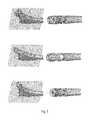
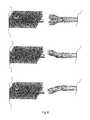
- FIG. 6illustrates possible neck positions.
- FIG. 7illustrates possible neck positions.
- FIG. 8illustrates possible neck positions.
- FIG. 9illustrates possible neck positions.
- FIG. 1is an enlarged diagram illustrating the various possible geometrical characteristics of each neck forming the set.
- FIG. 2is another view showing the neck orientation.
- thisshows that nine mutually equidistant points P i are arranged in threes in three horizontal parallel rows R o , which are likewise equidistant from each other.
- Part of the stem 2is inserted into a femur 4 , into which there is inserted by known methods one end of a mobile neck 1 i belonging to the set of the invention, the free end 3 i of which is shaped to allow it to be housed in a spherical head (not shown).
- the free end 3 iterminates along the axis H-H of the mobile neck at one of the points P i , marked P o in the drawing figures, and therefore has a length L and an inclination of 45° corresponding to a neutral neck, that is neither varus nor valgus.
- This neck 1 i(which in the FIGURE terminates as stated at the point P o ) gives rise to one particular off-set measurement O and one particular height measurement B. If the anatomical structure of the patient requires the same off-set but a height B′ smaller than B, the surgeon simply chooses from the set of mobile necks a neck of length L, of which only the axis R-R is shown with a smaller inclination, and the desired result is obtained.
- the mobile necksare inclined in anteversion and retroversion, that is with respect to the plane a containing the centers of the articulations of the two legs of the patient, it is sufficient, given the symmetry of the prostheses of limbs, to give the desired different inclinations to a limited number of mobile necks within the set of the invention, with the result already described earlier that as few as 15 mobile necks 1 i , all different from each other, as stated, can create a set complete enough to be used in practically all cases normally treated.
- the inventorrecommends that the distance between the points P i be approximately 7.5 mm in both directions, so that the square Q enclosing them has a side of length of about 15 mm.
- length (L, L 1 , L 2 ) of a mobile neckis the actual axial length of the mobile neck when the inclination of the latter is not corrected in either anteversion or retroversion. In the other cases this length corresponds to the projection onto the abovementioned plane of the actual length of the mobile neck.
- three necksmay be exempt from reaching two points by rotation. With only fifteen necks it is possible to fit any patient. In fact, the fifteen necks of the present application allow to cover all the points in the space, these points being obtained by varying one variable at a time, while keeping the other two variable constant.
- each neckcan reach two symmetrical points in the space, rotating the neck by 180°.
- free ends of the fifteen necksmay terminate at twenty seven mutually equidistant points arranged in three parallel rows located in three parallel equidistant planes, the two points in a space such that the neck can reach being symmetric with respect to a central point of one of the three parallel equidistant planes in which the twenty seven mutually equidistant points are arranged.
- nine necks ofare meant to terminate each at one point, thus creating nine points total.
- FIGS. 1-5As to the fifteen necks of which three cannot be rotated to reach two points, this is clear in FIGS. 1-5 that the twenty seven points in the space, are arranged on three different and parallel planes.
- the geometry of the present inventioncan be further elucidated in light of FIGS. 3-9 .
- the “offset”, that is, the distance between the axis of the femur and the (parallel) axis of the femur headis optimum.
- the surgeonOn the front plane the surgeon has to position the prosthesis so that the length of the limb after the surgery is the correct one. In other words, the length of the leg has to be the correct one without altering the tension of the muscles that had been previously determined.
- the surgeonOn the sagittal plane, the surgeon has to position the prosthesis so that it is stable.
- CCD angleis defined, as illustrated in FIG. 3 , which is the angle between the axis of the femur and the axis of the femur neck.
- each bi-dimensional matrixrepresents nine positions arranged in column of 3 ⁇ 3 positions.
- the three matriceswhen arranged one parallel to the other, define a “cube” that is a three-dimensional figure.
- each row of the matrixdefines three points having the same height, while each column of the matrix defines three points having the same offset.
- FIGS. 6 , 7 , 8 and 9The possible neck positions are illustrated in FIGS. 6 , 7 , 8 and 9 .
Landscapes
- Health & Medical Sciences (AREA)
- Orthopedic Medicine & Surgery (AREA)
- Cardiology (AREA)
- Oral & Maxillofacial Surgery (AREA)
- Transplantation (AREA)
- Engineering & Computer Science (AREA)
- Biomedical Technology (AREA)
- Heart & Thoracic Surgery (AREA)
- Vascular Medicine (AREA)
- Life Sciences & Earth Sciences (AREA)
- Animal Behavior & Ethology (AREA)
- General Health & Medical Sciences (AREA)
- Public Health (AREA)
- Veterinary Medicine (AREA)
- Prostheses (AREA)
Abstract
Description
Claims (12)
Priority Applications (1)
| Application Number | Priority Date | Filing Date | Title |
|---|---|---|---|
| US12/720,141US8357204B2 (en) | 2003-09-18 | 2010-03-09 | Set of mobile necks for inserting into the stem of a hip prosthesis |
Applications Claiming Priority (6)
| Application Number | Priority Date | Filing Date | Title |
|---|---|---|---|
| CH01599/03 | 2003-09-18 | ||
| CH1599/03 | 2003-09-18 | ||
| CH01599/03ACH697226B1 (en) | 2003-09-18 | 2003-09-18 | Set of furniture packages to be included in the stem of a hip prosthesis. |
| US10/547,150US20060173549A1 (en) | 2003-09-18 | 2004-09-02 | Set of mobile necks for inserting into the stem of a hip prosthesis |
| PCT/IB2004/002874WO2005025460A1 (en) | 2003-09-18 | 2004-09-02 | Set of mobile necks for inserting into the stem of a hip prosthesis |
| US12/720,141US8357204B2 (en) | 2003-09-18 | 2010-03-09 | Set of mobile necks for inserting into the stem of a hip prosthesis |
Related Parent Applications (3)
| Application Number | Title | Priority Date | Filing Date |
|---|---|---|---|
| PCT/IB2004/002874Continuation-In-PartWO2005025460A1 (en) | 2003-09-18 | 2004-09-02 | Set of mobile necks for inserting into the stem of a hip prosthesis |
| US10/547,150Continuation-In-PartUS20060173549A1 (en) | 2003-09-18 | 2004-09-02 | Set of mobile necks for inserting into the stem of a hip prosthesis |
| US11/547,150Continuation-In-PartUS20070189741A1 (en) | 2004-03-31 | 2005-03-31 | Electric fluid heater |
Publications (2)
| Publication Number | Publication Date |
|---|---|
| US20110125285A1 US20110125285A1 (en) | 2011-05-26 |
| US8357204B2true US8357204B2 (en) | 2013-01-22 |
Family
ID=44063480
Family Applications (1)
| Application Number | Title | Priority Date | Filing Date |
|---|---|---|---|
| US12/720,141Expired - Fee RelatedUS8357204B2 (en) | 2003-09-18 | 2010-03-09 | Set of mobile necks for inserting into the stem of a hip prosthesis |
Country Status (1)
| Country | Link |
|---|---|
| US (1) | US8357204B2 (en) |
Cited By (7)
| Publication number | Priority date | Publication date | Assignee | Title |
|---|---|---|---|---|
| US20160256288A1 (en)* | 2013-10-13 | 2016-09-08 | 41Medical Ag | Shoulder prosthesis assembly |
| US20160361173A1 (en)* | 2006-03-21 | 2016-12-15 | Tornier, Inc. | Femoral and humeral stem geometry and implantation method for orthopedic joint reconstruction |
| US10548737B2 (en) | 2011-10-31 | 2020-02-04 | Tornier Orthopedics Ireland Ltd. | Reverse shoulder prostheses with anti-rotation features |
| US10973645B2 (en) | 2012-10-29 | 2021-04-13 | Tornier Orthopedics Ireland, Ltd. | Systems for reverse shoulder implants |
| US10987226B2 (en) | 2016-04-19 | 2021-04-27 | Imascap Sas | Pre-operatively planned humeral implant and planning method |
| US11173037B2 (en) | 2014-12-10 | 2021-11-16 | Tornier Sas | Convertible stem / fracture stem |
| USD938590S1 (en) | 2019-10-01 | 2021-12-14 | Howmedica Osteonics Corp. | Humeral implant |
Families Citing this family (6)
| Publication number | Priority date | Publication date | Assignee | Title |
|---|---|---|---|---|
| EP3355833B1 (en)* | 2015-09-30 | 2023-01-11 | David Phillip Kirwan | Hip prosthesis |
| FR3050107B1 (en)* | 2016-04-19 | 2018-04-27 | Hip Hip Hip | RANGE OF FEMALE PROSTHESES |
| FR3050106B1 (en)* | 2016-04-19 | 2018-04-27 | Hip Hip Hip | RANGE OF LATERALIZED FEMALE PROSTHESES |
| CN107518964B (en)* | 2017-08-15 | 2023-07-28 | 北京爱康宜诚医疗器材有限公司 | Femoral prosthesis and method for manufacturing femoral prosthesis |
| CN107496058B (en)* | 2017-08-15 | 2023-07-28 | 北京爱康宜诚医疗器材有限公司 | femoral prosthesis |
| US11369492B2 (en)* | 2017-08-22 | 2022-06-28 | Depuy Ireland Unlimited Company | Trial neck |
Citations (10)
| Publication number | Priority date | Publication date | Assignee | Title |
|---|---|---|---|---|
| US4608055A (en) | 1984-01-12 | 1986-08-26 | Mayo Foundation | Femoral component for hip prosthesis |
| EP0201407A1 (en) | 1985-04-24 | 1986-11-12 | Patrick Montagne | Set of parts for forming a femoral prosthesis |
| DE3600804C1 (en) | 1986-01-14 | 1987-08-13 | Orthoplant Endoprothetik | Hip joint prosthesis with condyle connector |
| US4822370A (en)* | 1986-01-14 | 1989-04-18 | Orthoplant Endoprothetik | Hip joint femoral prosthesis |
| US4963155A (en) | 1989-08-30 | 1990-10-16 | Zimmer, Inc. | Attachment mechanism for modular surgical products |
| DE4407227A1 (en) | 1992-11-17 | 1995-09-07 | Medinov Sa | Femoral prosthesis assembly |
| US5580352A (en) | 1990-06-06 | 1996-12-03 | Sekel; Ronald | Distal shaft with fast and slow screw threads |
| EP0797964A1 (en) | 1996-03-26 | 1997-10-01 | Groupe Lepine | Assembly of elements for the formation of a total hip prosthesis |
| US6299648B1 (en)* | 2000-03-17 | 2001-10-09 | Hammill Manufacturing Co. | Locking hip prosthesis |
| US20010049561A1 (en) | 1997-04-11 | 2001-12-06 | Dews Paul M. | Modular humeral prosthesis and method |
- 2010
- 2010-03-09USUS12/720,141patent/US8357204B2/ennot_activeExpired - Fee Related
Patent Citations (10)
| Publication number | Priority date | Publication date | Assignee | Title |
|---|---|---|---|---|
| US4608055A (en) | 1984-01-12 | 1986-08-26 | Mayo Foundation | Femoral component for hip prosthesis |
| EP0201407A1 (en) | 1985-04-24 | 1986-11-12 | Patrick Montagne | Set of parts for forming a femoral prosthesis |
| DE3600804C1 (en) | 1986-01-14 | 1987-08-13 | Orthoplant Endoprothetik | Hip joint prosthesis with condyle connector |
| US4822370A (en)* | 1986-01-14 | 1989-04-18 | Orthoplant Endoprothetik | Hip joint femoral prosthesis |
| US4963155A (en) | 1989-08-30 | 1990-10-16 | Zimmer, Inc. | Attachment mechanism for modular surgical products |
| US5580352A (en) | 1990-06-06 | 1996-12-03 | Sekel; Ronald | Distal shaft with fast and slow screw threads |
| DE4407227A1 (en) | 1992-11-17 | 1995-09-07 | Medinov Sa | Femoral prosthesis assembly |
| EP0797964A1 (en) | 1996-03-26 | 1997-10-01 | Groupe Lepine | Assembly of elements for the formation of a total hip prosthesis |
| US20010049561A1 (en) | 1997-04-11 | 2001-12-06 | Dews Paul M. | Modular humeral prosthesis and method |
| US6299648B1 (en)* | 2000-03-17 | 2001-10-09 | Hammill Manufacturing Co. | Locking hip prosthesis |
Cited By (17)
| Publication number | Priority date | Publication date | Assignee | Title |
|---|---|---|---|---|
| US10898336B2 (en)* | 2006-03-21 | 2021-01-26 | Tornier, Inc. | Femoral and humeral stem geometry and implantation method for orthopedic joint reconstruction |
| US20160361173A1 (en)* | 2006-03-21 | 2016-12-15 | Tornier, Inc. | Femoral and humeral stem geometry and implantation method for orthopedic joint reconstruction |
| US11679006B2 (en) | 2011-10-31 | 2023-06-20 | Tornier Orthopedics Ireland, Ltd. | Systems for shoulder prostheses |
| US10548737B2 (en) | 2011-10-31 | 2020-02-04 | Tornier Orthopedics Ireland Ltd. | Reverse shoulder prostheses with anti-rotation features |
| US10973645B2 (en) | 2012-10-29 | 2021-04-13 | Tornier Orthopedics Ireland, Ltd. | Systems for reverse shoulder implants |
| US12064353B2 (en) | 2012-10-29 | 2024-08-20 | Stryker European Operations Limited | Systems for reverse shoulder implants |
| US20160256288A1 (en)* | 2013-10-13 | 2016-09-08 | 41Medical Ag | Shoulder prosthesis assembly |
| US9999513B2 (en)* | 2013-10-13 | 2018-06-19 | 41Hemiverse Ag | Shoulder prosthesis assembly |
| US9925053B2 (en)* | 2013-10-13 | 2018-03-27 | 41Hemiverse Ag | Joint implant |
| US11173037B2 (en) | 2014-12-10 | 2021-11-16 | Tornier Sas | Convertible stem / fracture stem |
| US11471291B2 (en) | 2014-12-10 | 2022-10-18 | Tornier Sas | Convertible stem/fracture stem |
| US12343262B2 (en) | 2014-12-10 | 2025-07-01 | Tornier Sas | Convertible stem/fracture stem |
| US10987226B2 (en) | 2016-04-19 | 2021-04-27 | Imascap Sas | Pre-operatively planned humeral implant and planning method |
| US12109120B2 (en) | 2016-04-19 | 2024-10-08 | Stryker European Operations Limited | Pre-operatively planned humeral implant and planning method |
| USD938590S1 (en) | 2019-10-01 | 2021-12-14 | Howmedica Osteonics Corp. | Humeral implant |
| USD983373S1 (en) | 2019-10-01 | 2023-04-11 | Howmedica Osteonics Corp. | Humeral implant |
| USD1054031S1 (en) | 2019-10-01 | 2024-12-10 | Howmedica Osteonics Corp. | Humeral implant |
Also Published As
| Publication number | Publication date |
|---|---|
| US20110125285A1 (en) | 2011-05-26 |
Similar Documents
| Publication | Publication Date | Title |
|---|---|---|
| US8357204B2 (en) | Set of mobile necks for inserting into the stem of a hip prosthesis | |
| EP3946169B1 (en) | Stemmed implant | |
| US5370704A (en) | Oblong acetabular cup | |
| US6589282B2 (en) | Modular shoulder prostheses | |
| US7452379B2 (en) | Artificial vertebral disk replacement implant with crossbar spacer and method | |
| EP2319463B1 (en) | Mobile tibial bearing assembly | |
| US20030204267A1 (en) | Modular limb preservation system | |
| US8048167B2 (en) | Orthopaedic implant kit, orthopaedic surgery kit and associated method | |
| EP3042637A1 (en) | Reverse shoulder prosthesis | |
| KR20100085048A (en) | Modular necks for orthopaedic devices | |
| JP2005516673A (en) | Modular prosthesis including tapered adjustment | |
| US20020042655A1 (en) | Modular prosthetic component with improved body shape | |
| JP2009515610A (en) | Prosthesis assembly with angle / position adapter | |
| Verkerke et al. | An extendable modular endoprosthetic system for bone tumour management in the leg | |
| CA2628076A1 (en) | Single entry portal implant | |
| US20040138757A1 (en) | Eccentric neck for femoral hip prosthesis | |
| US20050055103A1 (en) | Femoral hip prosthesis part, a set of such femoral parts and the production method thereof | |
| CA2515363C (en) | Set of mobile necks for inserting into the stem of a hip prosthesis | |
| Mendes et al. | Classification of adult congenital hip dysplasia for total hip arthroplasty | |
| EP3212128B1 (en) | Humeral trays with tuberosity augments sufficiently designed to improve joint mechanics | |
| US20140257510A1 (en) | Anatomic monolithic hip implant system | |
| Karch et al. | A More Exact Way of Doing Things: Direct Anterior Approach to Hip Replacement |
Legal Events
| Date | Code | Title | Description |
|---|---|---|---|
| AS | Assignment | Owner name:MARIASAL INVESTMENT N.V., NETHERLANDS ANTILLES Free format text:ASSIGNMENT OF ASSIGNORS INTEREST;ASSIGNOR:RAGBIR, SHEILA;REEL/FRAME:024406/0734 Effective date:20100513 | |
| AS | Assignment | Owner name:DRAKKAR B.V., NETHERLANDS Free format text:ASSIGNMENT OF ASSIGNORS INTEREST;ASSIGNOR:MARIASAL INVESTMENT N.V.;REEL/FRAME:025805/0335 Effective date:20101216 | |
| AS | Assignment | Owner name:ADLER ORTHO S.R.L., ITALY Free format text:ASSIGNMENT OF ASSIGNORS INTEREST;ASSIGNOR:DRAKKAR B.V.;REEL/FRAME:026536/0696 Effective date:20101222 | |
| STCF | Information on status: patent grant | Free format text:PATENTED CASE | |
| FPAY | Fee payment | Year of fee payment:4 | |
| MAFP | Maintenance fee payment | Free format text:PAYMENT OF MAINTENANCE FEE, 8TH YR, SMALL ENTITY (ORIGINAL EVENT CODE: M2552); ENTITY STATUS OF PATENT OWNER: SMALL ENTITY Year of fee payment:8 | |
| FEPP | Fee payment procedure | Free format text:MAINTENANCE FEE REMINDER MAILED (ORIGINAL EVENT CODE: REM.); ENTITY STATUS OF PATENT OWNER: SMALL ENTITY | |
| LAPS | Lapse for failure to pay maintenance fees | Free format text:PATENT EXPIRED FOR FAILURE TO PAY MAINTENANCE FEES (ORIGINAL EVENT CODE: EXP.); ENTITY STATUS OF PATENT OWNER: SMALL ENTITY | |
| STCH | Information on status: patent discontinuation | Free format text:PATENT EXPIRED DUE TO NONPAYMENT OF MAINTENANCE FEES UNDER 37 CFR 1.362 | |
| FP | Lapsed due to failure to pay maintenance fee | Effective date:20250122 |