US8357168B2 - Modular injection needle and seal assembly - Google Patents
Modular injection needle and seal assemblyDownload PDFInfo
- Publication number
- US8357168B2 US8357168B2US11/850,424US85042407AUS8357168B2US 8357168 B2US8357168 B2US 8357168B2US 85042407 AUS85042407 AUS 85042407AUS 8357168 B2US8357168 B2US 8357168B2
- Authority
- US
- United States
- Prior art keywords
- needle
- annulus
- seal
- stop
- disc
- Prior art date
- Legal status (The legal status is an assumption and is not a legal conclusion. Google has not performed a legal analysis and makes no representation as to the accuracy of the status listed.)
- Expired - Fee Related, expires
Links
- 238000002347injectionMethods0.000titledescription93
- 239000007924injectionSubstances0.000titledescription93
- 239000012620biological materialSubstances0.000claimsabstractdescription17
- 238000007789sealingMethods0.000claimsabstractdescription17
- 239000000463materialSubstances0.000claimsdescription32
- 238000003466weldingMethods0.000claimsdescription2
- 238000000034methodMethods0.000description46
- 239000012530fluidSubstances0.000description15
- 238000003032molecular dockingMethods0.000description15
- 206010061246Intervertebral disc degenerationDiseases0.000description14
- 208000018180degenerative disc diseaseDiseases0.000description14
- 208000021600intervertebral disc degenerative diseaseDiseases0.000description14
- FAPWRFPIFSIZLT-UHFFFAOYSA-MSodium chlorideChemical compound[Na+].[Cl-]FAPWRFPIFSIZLT-UHFFFAOYSA-M0.000description10
- 229920000642polymerPolymers0.000description9
- 210000001519tissueAnatomy0.000description9
- 238000013459approachMethods0.000description7
- 210000003484anatomyAnatomy0.000description6
- 238000001356surgical procedureMethods0.000description6
- 230000001788irregularEffects0.000description5
- 238000012986modificationMethods0.000description5
- 230000004048modificationEffects0.000description5
- 238000012360testing methodMethods0.000description5
- 238000004873anchoringMethods0.000description4
- 238000003780insertionMethods0.000description4
- 230000037431insertionEffects0.000description4
- 208000003618Intervertebral Disc DisplacementDiseases0.000description3
- 239000000470constituentSubstances0.000description3
- 238000010276constructionMethods0.000description3
- 230000004927fusionEffects0.000description3
- 229920003023plasticPolymers0.000description3
- 239000004033plasticSubstances0.000description3
- 239000012858resilient materialSubstances0.000description3
- 239000011780sodium chlorideSubstances0.000description3
- 239000010963304 stainless steelSubstances0.000description2
- 206010019909HerniaDiseases0.000description2
- 241000283984RodentiaSpecies0.000description2
- 229910000589SAE 304 stainless steelInorganic materials0.000description2
- 230000003190augmentative effectEffects0.000description2
- 239000000560biocompatible materialSubstances0.000description2
- 230000000295complement effectEffects0.000description2
- 238000002594fluoroscopyMethods0.000description2
- 239000012634fragmentSubstances0.000description2
- 238000011065in-situ storageMethods0.000description2
- 230000001045lordotic effectEffects0.000description2
- 230000013011matingEffects0.000description2
- 239000000203mixtureSubstances0.000description2
- 210000005036nerveAnatomy0.000description2
- 238000002355open surgical procedureMethods0.000description2
- 230000001817pituitary effectEffects0.000description2
- 229920001296polysiloxanePolymers0.000description2
- 238000003825pressingMethods0.000description2
- 102000004169proteins and genesHuman genes0.000description2
- 108090000623proteins and genesProteins0.000description2
- 239000011347resinSubstances0.000description2
- 229920005989resinPolymers0.000description2
- 238000013022ventingMethods0.000description2
- DHKHKXVYLBGOIT-UHFFFAOYSA-N1,1-DiethoxyethaneChemical compoundCCOC(C)OCCDHKHKXVYLBGOIT-UHFFFAOYSA-N0.000description1
- 239000004971Cross linkerSubstances0.000description1
- 229920004943Delrin®Polymers0.000description1
- 241001269524DuraSpecies0.000description1
- 206010050296Intervertebral disc protrusionDiseases0.000description1
- 239000011354acetal resinSubstances0.000description1
- 230000001070adhesive effectEffects0.000description1
- 230000004075alterationEffects0.000description1
- 229920000249biocompatible polymerPolymers0.000description1
- 230000008859changeEffects0.000description1
- 230000001010compromised effectEffects0.000description1
- 230000002950deficientEffects0.000description1
- 230000018044dehydrationEffects0.000description1
- 238000006297dehydration reactionMethods0.000description1
- 238000013461designMethods0.000description1
- 238000001514detection methodMethods0.000description1
- 239000013536elastomeric materialSubstances0.000description1
- 238000005516engineering processMethods0.000description1
- 238000011156evaluationMethods0.000description1
- 238000002685hemilaminectomyMethods0.000description1
- 239000000017hydrogelSubstances0.000description1
- 230000010354integrationEffects0.000description1
- 238000011835investigationMethods0.000description1
- 238000002684laminectomyMethods0.000description1
- 210000004749ligamentum flavumAnatomy0.000description1
- 238000002324minimally invasive surgeryMethods0.000description1
- 210000003205muscleAnatomy0.000description1
- 230000037361pathwayEffects0.000description1
- 230000000704physical effectEffects0.000description1
- 229920006324polyoxymethylenePolymers0.000description1
- 229920002635polyurethanePolymers0.000description1
- 239000004814polyurethaneSubstances0.000description1
- 230000008569processEffects0.000description1
- 230000001737promoting effectEffects0.000description1
- 229920000260silasticPolymers0.000description1
- 239000000243solutionSubstances0.000description1
- 229910001220stainless steelInorganic materials0.000description1
- 239000010935stainless steelSubstances0.000description1
- 238000007920subcutaneous administrationMethods0.000description1
- 210000003813thumbAnatomy0.000description1
- 238000011144upstream manufacturingMethods0.000description1
- 238000012800visualizationMethods0.000description1
Images


Classifications
- A—HUMAN NECESSITIES
- A61—MEDICAL OR VETERINARY SCIENCE; HYGIENE
- A61M—DEVICES FOR INTRODUCING MEDIA INTO, OR ONTO, THE BODY; DEVICES FOR TRANSDUCING BODY MEDIA OR FOR TAKING MEDIA FROM THE BODY; DEVICES FOR PRODUCING OR ENDING SLEEP OR STUPOR
- A61M5/00—Devices for bringing media into the body in a subcutaneous, intra-vascular or intramuscular way; Accessories therefor, e.g. filling or cleaning devices, arm-rests
- A61M5/46—Devices for bringing media into the body in a subcutaneous, intra-vascular or intramuscular way; Accessories therefor, e.g. filling or cleaning devices, arm-rests having means for controlling depth of insertion
- A—HUMAN NECESSITIES
- A61—MEDICAL OR VETERINARY SCIENCE; HYGIENE
- A61F—FILTERS IMPLANTABLE INTO BLOOD VESSELS; PROSTHESES; DEVICES PROVIDING PATENCY TO, OR PREVENTING COLLAPSING OF, TUBULAR STRUCTURES OF THE BODY, e.g. STENTS; ORTHOPAEDIC, NURSING OR CONTRACEPTIVE DEVICES; FOMENTATION; TREATMENT OR PROTECTION OF EYES OR EARS; BANDAGES, DRESSINGS OR ABSORBENT PADS; FIRST-AID KITS
- A61F2/00—Filters implantable into blood vessels; Prostheses, i.e. artificial substitutes or replacements for parts of the body; Appliances for connecting them with the body; Devices providing patency to, or preventing collapsing of, tubular structures of the body, e.g. stents
- A61F2/02—Prostheses implantable into the body
- A61F2/30—Joints
- A61F2/46—Special tools for implanting artificial joints
- A61F2/4603—Special tools for implanting artificial joints for insertion or extraction of endoprosthetic joints or of accessories thereof
- A61F2/4611—Special tools for implanting artificial joints for insertion or extraction of endoprosthetic joints or of accessories thereof of spinal prostheses
- A—HUMAN NECESSITIES
- A61—MEDICAL OR VETERINARY SCIENCE; HYGIENE
- A61B—DIAGNOSIS; SURGERY; IDENTIFICATION
- A61B17/00—Surgical instruments, devices or methods
- A61B17/56—Surgical instruments or methods for treatment of bones or joints; Devices specially adapted therefor
- A61B17/58—Surgical instruments or methods for treatment of bones or joints; Devices specially adapted therefor for osteosynthesis, e.g. bone plates, screws or setting implements
- A61B17/88—Osteosynthesis instruments; Methods or means for implanting or extracting internal or external fixation devices
- A61B17/8802—Equipment for handling bone cement or other fluid fillers
- A61B17/8805—Equipment for handling bone cement or other fluid fillers for introducing fluid filler into bone or extracting it
- A61B17/8808—Equipment for handling bone cement or other fluid fillers for introducing fluid filler into bone or extracting it with sealing collar for bone cavity
- A—HUMAN NECESSITIES
- A61—MEDICAL OR VETERINARY SCIENCE; HYGIENE
- A61B—DIAGNOSIS; SURGERY; IDENTIFICATION
- A61B17/00—Surgical instruments, devices or methods
- A61B17/56—Surgical instruments or methods for treatment of bones or joints; Devices specially adapted therefor
- A61B17/58—Surgical instruments or methods for treatment of bones or joints; Devices specially adapted therefor for osteosynthesis, e.g. bone plates, screws or setting implements
- A61B17/88—Osteosynthesis instruments; Methods or means for implanting or extracting internal or external fixation devices
- A61B17/8802—Equipment for handling bone cement or other fluid fillers
- A61B17/8805—Equipment for handling bone cement or other fluid fillers for introducing fluid filler into bone or extracting it
- A61B17/8827—Equipment for handling bone cement or other fluid fillers for introducing fluid filler into bone or extracting it with filtering, degassing, venting or pressure relief means
- A—HUMAN NECESSITIES
- A61—MEDICAL OR VETERINARY SCIENCE; HYGIENE
- A61F—FILTERS IMPLANTABLE INTO BLOOD VESSELS; PROSTHESES; DEVICES PROVIDING PATENCY TO, OR PREVENTING COLLAPSING OF, TUBULAR STRUCTURES OF THE BODY, e.g. STENTS; ORTHOPAEDIC, NURSING OR CONTRACEPTIVE DEVICES; FOMENTATION; TREATMENT OR PROTECTION OF EYES OR EARS; BANDAGES, DRESSINGS OR ABSORBENT PADS; FIRST-AID KITS
- A61F2/00—Filters implantable into blood vessels; Prostheses, i.e. artificial substitutes or replacements for parts of the body; Appliances for connecting them with the body; Devices providing patency to, or preventing collapsing of, tubular structures of the body, e.g. stents
- A61F2/02—Prostheses implantable into the body
- A61F2/30—Joints
- A61F2/30767—Special external or bone-contacting surface, e.g. coating for improving bone ingrowth
- A61F2/30771—Special external or bone-contacting surface, e.g. coating for improving bone ingrowth applied in original prostheses, e.g. holes or grooves
- A61F2002/3085—Special external or bone-contacting surface, e.g. coating for improving bone ingrowth applied in original prostheses, e.g. holes or grooves with a threaded, e.g. self-tapping, bone-engaging surface, e.g. external surface
- A—HUMAN NECESSITIES
- A61—MEDICAL OR VETERINARY SCIENCE; HYGIENE
- A61F—FILTERS IMPLANTABLE INTO BLOOD VESSELS; PROSTHESES; DEVICES PROVIDING PATENCY TO, OR PREVENTING COLLAPSING OF, TUBULAR STRUCTURES OF THE BODY, e.g. STENTS; ORTHOPAEDIC, NURSING OR CONTRACEPTIVE DEVICES; FOMENTATION; TREATMENT OR PROTECTION OF EYES OR EARS; BANDAGES, DRESSINGS OR ABSORBENT PADS; FIRST-AID KITS
- A61F2/00—Filters implantable into blood vessels; Prostheses, i.e. artificial substitutes or replacements for parts of the body; Appliances for connecting them with the body; Devices providing patency to, or preventing collapsing of, tubular structures of the body, e.g. stents
- A61F2/02—Prostheses implantable into the body
- A61F2/30—Joints
- A61F2/44—Joints for the spine, e.g. vertebrae, spinal discs
- A61F2/442—Intervertebral or spinal discs, e.g. resilient
- A61F2002/444—Intervertebral or spinal discs, e.g. resilient for replacing the nucleus pulposus
Definitions
- the present inventionrelates to systems and methods for the treatment of the spine, and especially the interbody disc space. More specifically, the invention concerns the injection of a biomaterial into a spinal space, such as the intradiscal space.
- Spine fusion proceduresrepresent the state of the art treatment for intervertebral disc problems, which generally involve open surgery and the use of interbody fusion cages and spinal fixation systems to stabilize the fusion site.
- An alternative treatment under evaluationis to replace or augment the disc or nucleus pulposus with a prosthetic device.
- Examples of some devices currently under investigationinclude in-situ cured polymers such as polyurethanes and protein polymers, which may have properties varying from a rubbery hydrogel to a rigid plastic. Problems associated with these devices occur during insertion, whereby the pressure required to fill the disc space can cause leakage of the material into sensitive adjacent areas.
- a number of devicesare available for distracting vertebral bodies or for injecting material into the disc. Some devices are capable of both distraction and injection using the same instrument. These types of devices use a deflated balloon attached to a cannula and inserted between the vertebral bodies. The balloon is inflated with a prosthetic fluid through the cannula to distract the vertebral bodies. This requires high-pressure delivery of the fluid to achieve the pressure needed to distract the vertebral bodies and the balloon and fluid permanently remain in the disc space. Alternatively, a separate device is used to inject the prosthetic fluid around the balloon and the balloon is used strictly for distraction after which it is deflated and removed.
- the present inventioncontemplates a modular injection needle assembly.
- the assemblyincludes an injection needle which includes an injection cannula for introduction of a fluent biomaterial, such as an injectable nucleus material, into a disc space.
- the injection needlemay also include a vent cannula for venting fluid from the disc space as it is being filled with the biomaterial.
- the injection needleis provided with a stop that is integral with or fastened to the needle.
- the stopmay be positioned at different distances from the distal end of the needle.
- a kitis provided with a selection of injection needles with stops at these different distances.
- a mountable and removable sealis also provided with the injection needle assembly.
- the sealis configured to seat against the stop and maintain its position until removed after the procedure is complete.
- the inventioncontemplates a variety of seal configurations from which the surgeon may select a configuration that is optimum for the particular surgical procedure and disc anatomy.
- the variety of seal configurationsincludes cylindrical and elliptical seals and cup-shaped seals that are configured for fluid-tight contact with the outer surface of the annulus.
- the variety of sealsalso includes conical seals that are configured to be pressed into an opening in the annulus.
- the sealsmay include self-anchoring features, such as external threads on the conical seals.
- sealsmay be provided in a kit, along with the selection of injection needles.
- surgeonmay create an injection needle assembly that is optimized for the patient and the procedure.
- FIG. 1is an enlarged pictorial view of a vented injection needle for introduction of curable biomaterial into a disc space.
- FIG. 2is a front perspective enlarged view of the vented injection needle shown in FIG. 1 .
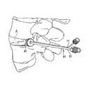
- FIG. 3is a lateral pictorial view of the spine with an injection assembly positioned to introduce a curable biomaterial into an affected disc in a percutaneous procedure.
- FIG. 4is an enlarged view of the disc shown in FIG. 3 with the injection needle and docking cannula of the injection assembly positioned within the disc annulus.
- FIG. 5is an enlarged view of a disc with a docking cannula according to a further embodiment with the injection needle extending therethrough into the disc space.
- FIG. 6is an enlarged cross-sectional view of the docking cannula and injection needle depicted in FIG. 5 .
- FIG. 7is an enlarged view of a disc with a docking cannula according to a further embodiment with the injection needle extending therethrough into the disc space.
- FIG. 8is an enlarged cross-sectional view of the docking cannula and injection needle depicted in FIG. 7 .
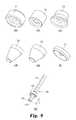
- FIGS. 9( a )- 9 ( g )are perspective views of an injection needle assembly with a modular seal in accordance with the present invention, and of several modular seals for use with the needle assembly.
- FIGS. 10( a )- 10 ( b )are side and top views of the injection needle assembly shown in FIG. 9( g ).
- FIGS. 11( a )- 11 ( d )are side, perspective, top and cross-sectional views of a stop mounted to the injection needle of the assembly of FIGS. 9-10 .
- FIGS. 12( a )- 12 ( b )are perspective and cross-sectional views of a cylindrical seal for use with the needle assembly shown in FIG. 9 .
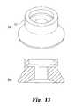
- FIGS. 13( a )- 13 ( b )are perspective and cross-sectional views of a cup-shaped seal for use with the needle assembly shown in FIG. 9 .
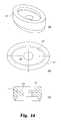
- FIGS. 14( a )- 14 ( c )are perspective, top and cross-sectional views of an elliptical seal for use with the needle assembly shown in FIG. 9 .
- FIGS. 15( a )- 15 ( b )are perspective and cross-sectional views of a bearing member for use with the elliptical seal shown in FIG. 14 .
- FIGS. 16( a )- 16 ( b )are perspective and exploded views of another cylindrical seal for use with the needle assembly shown in FIG. 9 .
- FIGS. 17( a )- 17 ( b )are perspective and cross-sectional views of the seal body of the cylindrical seal shown in FIG. 16 .
- FIGS. 18( a )- 18 ( b )are perspective and cross-sectional views of a bearing member for use with the cylindrical seal shown in FIG. 17 .
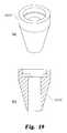
- FIGS. 19( a )- 19 ( b )are perspective and cross-sectional views of the seal body of a conical seal for use with the needle assembly shown in FIG. 9 .
- FIG. 20( a )is a side partial cross-sectional view of an alternative articulating seal assembly with the needle assembly shown in FIG. 9 .
- FIG. 20( b )is a top view of the articulating seal shown in FIG. 20( a ).
- FIG. 20( c )is an end view of the needle in the assembly of FIG. 20( a ).
- FIG. 20( d )is an end view of the assembly shown in FIG. 20( a ).
- FIG. 21( a )is a side view of the articulating seal assembly shown in FIG. 20( a ) with the seal oriented at an angle relative to the needle.
- FIG. 21( b )is a side view of the articulating needle assembly shown in FIG. 20 .
- FIGS. 22( a )- 22 ( c )are side, cross-sectional and perspective views of a self-anchoring seal for use with the needle assembly shown in FIG. 9 .
- an injectable nucleusis surgically introduced into the spine as a replacement for or augment to the natural nucleus pulposus.
- the injectable nucleusis preferably a curable biocompatible polymer with properties that emulate those of the natural human disc.
- a suitable injectable nucleus materialis disclosed in U.S. Pat. Nos. 6,423,333; 6,033,654; and 5,817,303, which issued to Protein Polymer Technologies, Inc. The disclosures of these patents are incorporated herein by reference. These patents disclose a proteinaceous curable polymer that has physical properties close to those of the human disc nucleus pulposus and that includes certain adhesive properties that allow the polymer to adhere to the disc annulus and any remaining disc nucleus pulposus.
- the constituents of the injectable nucleus materialare prepared in a mixing system, such as the mixing system disclosed in co-pending, commonly assigned patent application Ser. No. 10/803,214, entitled “Systems and Methods for Mixing Fluids”, the disclosure of which is incorporated herein by reference.
- the mixing systemis placed on the sterile table until it is needed for the mixing and injection step.
- the biomaterialis an injectable nucleus
- access to the intradiscal spaceis required. While many surgical approaches may be used, in one specific embodiment, the surgeon will use an extraforaminal mini-open approach to the disc. This may be either by a lateral retroperitoneal approach or a paramedian approach through the paraspinal muscles of the back. Access to the nucleus is gained through an extraforaminal annulotomy, so as to not expose the spinal canal or foramen to any undue risk. The annulus is identified and a minimal annulotomy is performed to gain access to the intradiscal space. The nucleus pulposus is then partially or completely removed using known techniques, such as using pituitary rongeurs and/or curettes. The nucleotomy should be fully irrigated once all loose fragments have been manually removed.
- the size of the spacemay be verified, such as by visualization and/or use of a saline injected balloon.
- the disc spacemay be distracted using several techniques. In one technique, distraction of the disc is accomplished using a non-compliant inflatable spherical balloon, such as a 15 mm diameter spherical balloon.
- the distraction toolsuch as the spherical balloon
- a trial balloonmay be used again to estimate the volume of injectable nucleus needed to the fill the distracted space.
- an injection needlemay be provided as part of an injection assembly 40 , as shown in FIG. 1 . Details of the injection assembly 40 may be gleaned from previously incorporated co-pending application Ser. No. 11/170,010, and particularly the description associated with FIGS. 13-16 thereof, the disclosure of which is incorporated herein by reference.
- the injection needle 42extends through a seal element 46 that is configured to provide an essentially fluid tight seal against the disc annulus A.
- a vent 44also extends through the seal 46 .
- the seal 46is shown in more detail in FIG. 2 .
- the seal 46includes a body 48 that is preferably formed of a resilient material that can be compressed slightly under manual pressure to conform to the irregular external surface of the disc.
- the body 48defines a sealing face 50 that bears against the disc annulus A ( FIG. 1 ) to create a fluid tight seal.
- the boss 52Extending from the sealing face 50 is an engagement boss 52 .
- the boss 52is preferably configured in accordance with the shape of the annulotomy cut into the annulus. As illustrated in FIG. 2 , the boss 52 is also cruciate in shape with wings 53 that are sized to fit within corresponding legs of a cruciate cut into the annulus A. The leading edges 53 a of the wings 53 can be rounded to facilitate placement of the boss 52 within the annulotomy.
- the vent 44provides an additional wing 57 for the boss 52 .
- the wing 57includes a channel 58 that integrates with the hollow vent 44 .
- the vent wing 57is co-extensive with the other wings of the boss 52 .
- the working end of the wing 57can project slightly farther into the disc space.
- the injection needle 42feeds to a channel 55 defined in the boss 52 to provide a pathway for the injectable nucleus into the disc cavity.
- the needleis introduced through the annulotomy, while carefully retracting the nerve root, until the seal 46 seats against the annulus.
- the needleis positioned so that the vent 44 is facing upward during the injection, as depicted in FIG. 1 .
- Pressureis applied to the seal 46 to ensure that no injectable nucleus leaks out between the seal and annulus.
- this pressureis applied manually by the surgeon by simply pressing the injection catheter 42 toward the annulus. Since the injectable nucleus injection occurs at low pressures, the amount of force required to maintain a fluid-tight seal between the seal face 50 and the annulus is minimal.
- the injectable nucleusis injected into the space until injectable nucleus is seen flowing through or out of the vent tube. At this point, the injection is stopped and the needle is held in place until the injectable nucleus takes its initial set. A microscope or loupe may be used to visualize the injection process.
- the injectable nucleus compositionis preferably allowed to substantially completely cure before the injection needle assembly 40 is removed and the surgical site is closed. The cure period depends upon the particular injectable nucleus material. For the specific proteinaceous polymer discussed above, the cure period is a minimum of about five minutes.
- the seal 46is formed of a resilient and deformable material so that it can be compressed against the annulus A to form a fluid tight seal.
- the seal 46is formed of SILASTIC® or a similar elastomeric material.
- the seal 46 in the illustrated embodimentis cylindrical with a circular sealing face 50 ; however, other configurations are contemplated provided they can adequately conform to the outer surface of the disc annulus.
- DDDdegenerative disc disease
- the annulusis typically relatively intact so that a minimal annulotomy is required to gain access to the intradiscal space. It is preferred that the opening is as small as feasible to minimize damage to the annulus.
- accesscan be via a K-wire over which a dilator, or a series of dilators, is passed.
- the nucleus pulposusmay be significantly under-hydrated or may contain fissures throughout the nucleus material, producing patient pain and giving rise to the need for a total or substantially total discectomy.
- the surgeonmay also chose to perform an intraoperative step of determining the integrity of the annulus, to confirm that the annulus is competent to withstand the distraction and injectable nucleus injection pressures.
- a saline solutionmay be injected into the intradiscal space through the annulotomy opening.
- a saline solutionis preferred since it is relatively easy to aspirate for removal from the intradiscal space.
- suitable solutionsmay also be used.
- the saline solutionmay be injected through a vented needle, in design and construction similar to the needle 40 shown in FIGS. 1-2 .
- this stepevaluates the integrity of the disc annulus—i.e., detects whether fissures or rents may be present in the annulus. This detection may be by tactile feel and/or by observation of leakage only at the injection needle site.
- the injected saline solutionmay be used to determine the volume of the disc space to be filled with injectable nucleus material.
- a trial balloonmay be used to ascertain the volume of the intradiscal space to be filled.
- suctionis applied to aspirate the nuclear cavity and a surgical swab may be used to wick away excess moisture that may interfere with the injection of the injectable nucleus material.
- the surgeonmay use a distraction balloon to apply a distraction force within the intradiscal space to distract the opposing vertebral bodies on either side of the intradiscal space, further separating apart such vertebral bodies.
- a subsequent saline testmay be conducted to further verify the integrity of the annulus.
- the injectable nucleusmay then be sealably injected under pressure using the vented needle 40 as described hereinabove.
- Such injection of injectable nucleusis preferred to be at a pressure that is not greater than the pressure under which the saline solution is injected and is typically on the order of 25-40 psi. While the saline solution has been described as preferably being injected with a vented needle such as described herein, it should be appreciated that a needle without a vent, but with a sealing element, could also be used in the practice of the annulus integrity test.
- AMDadjunct to microdiscectomy
- An AMD procedureis indicated where a total discectomy is not required, or more particularly where only a partial discectomy is necessary to restore normal or near normal function to the affected disc.
- the affected dischas a herniation or tear in the disc annulus. Access to the intradiscal space is thus available through the tear in the annulus.
- the injectable curable polymer constituentsPrior to the start of the surgery, the injectable curable polymer constituents are pre-loaded into the mixing assembly, as described above, and left on the sterile instrument table until the appropriate time for injection of the injectable nucleus material.
- the surgeonuses a traditional open or microdiscectomy technique of preference for access to the disc herniation site.
- the patientwill be placed on a laminectomy frame in the prone position with the spine flexed to aid intraoperative exposure.
- the ligamentum flavum and laminar edgeare identified.
- a hemilaminectomy/medial facetectomymay be performed as necessary, with the aid of lateral fluoroscopy. Exposure of the hernia proceeds in a known manner, taking care to protect the dura and nerve root.
- the epidural spaceis explored to ensure that all disc fragments have been identified.
- annulotomymay be performed as described above.
- the herniated disc tissueis then removed according to known techniques, such as using pituitary rongeurs and/or curettes. Laminar distraction and/or flexion of the hips can be used to aid in exposure of the hernia site.
- distraction of the affected discmay be desired to improve the stability of the disc. This distraction may be accomplished using any of the techniques described above. If sufficient disc tissue has been removed around the herniation site, a distraction balloon may be used, provided that the balloon is removed once the desired distraction has been achieved.
- the balloon distractionmay also be supplemented in a two stage distraction technique described as follows. After a total or partial nucleotomy has been performed, in the first stage, a distraction balloon is inserted into the intradiscal space. The balloon is then inflated to gain distraction of the anterior column of the disc space.
- a secondary distraction instrumentis introduced to act on any posterior bony structures at the particular intervertebral level in accordance with known surgical techniques.
- the secondary instrumentis used to obtain distraction of the posterior column at an appropriate amount decided by the surgeon.
- the nature and amount of this second stage distractionmay increase the overall amount of distraction of the total space, change the lordotic angle at the intervertebral level or cause no appreciable increase in the overall distraction of the space.
- the first stage distraction balloonis removed, while the secondary instrument remains in place to prevent any loss of distraction that may occur.
- the injectable nucleusmay be injected as described above.
- a saline solution as described above with respect to the DDD proceduremay be injected through a vented needle into the intradiscal space to check the integrity of the annulus and to determine that there are no other leakage paths, as well as to estimate the volume of the intradiscal space to be filled. While this annulus integrity test is described as being conducted after distraction, it may also be done after removal of nucleus and prior to distraction.
- the surgeonmixes the injectable nucleus constituents, as described above, to prepare the injectable nucleus material for injection.
- An injection needle(which is not required to be a vented and sealed needle) is introduced through the opening in the annulus until the needle tip reaches the far side of the cavity.
- the needleis preferably angled side-to-side and gradually withdrawn toward the annulus to ensure a complete fill of the space.
- the injectable nucleus materialis detected at the inner border of the annulus opening, the injection is stopped and the needle is removed from the site.
- a vented needle 40 with a seal 46may be used, such as where the rent through the annulus is relatively small and not too irregular.
- the injectionis stopped when the injectable nucleus material is seen at the vent. It is contemplated that the injectable nucleus material will be injected under pressure, typically on the order of 25-40 psi, to ensure complete fill of the cavity, with the seal 46 of the vented needle 40 being pressed against the annulus during injectable nucleus injection.
- Another procedure for percutaneous direct injection of a curable biomaterial for treatment of degenerative disc diseaseis indicated where the disc annulus is generally intact, but the nucleus pulposus has been compromised, either by dehydration or the creation of fissures and the patient suffers from significant pain.
- some or all of the nucleusis removed to create an intradiscal space for injection of curable biomaterial.
- the defective or degenerated nucleusis not removed, but is instead augmented by a curable biomaterial or injectable nucleus material in a percutaneous procedure.
- a percutaneous procedureaccess to the spinal disc is achieved simply by introduction of a relatively small and sharp cannulated device, which may include a needle, through the skin and body tissue down to the surgical site under fluoroscopy or by using other conventional surgical navigation techniques. No incision is made nor is any body tissue retracted. Further, injection is continued by insertion of the cannulated device through the annulus into the nucleus pulposus, preferably without additional dilators and without removing any of the annulus tissue. As such, a percutaneous procedure provides a minimally invasive approach to treating DDD conditions.
- the injectable nucleus materialis prepared in the same manner described above, with the loaded mixing assembly and crosslinker syringes made available on a sterile instrument table until the appropriate time for injection of the injectable nucleus material.
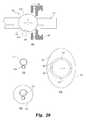
- an injection assembly 70 shown in FIG. 3may be used to accomplish the injection step. Details of the injection assembly may be obtained from previously incorporated co-pending application Ser. No. 11/170,657 with particular attention to FIGS. 19-20 thereof, the disclosure of which is incorporated herein by reference.
- the assembly 70includes a sharp cannulated device, such as a thin-walled docking cannula 72 with an integral mating hub 76 .
- the cannula 72has a relatively smooth outer surface and substantially constant outer and inner diameters along its length.
- An injection needle 74( FIG. 4 ) is slidably disposed within the docking cannula in a relatively close dimensional fit.
- the needle 74is integral with a hub 78 that may be configured to mate with the hub 76 of the cannula.
- a stopcock valve 80is fluidly connected to the hub 78 , and the injection syringe 82 is configured to engage the stopcock valve in any known manner effective to create a fluid tight connection.
- the patientis preferably placed in a prone position on an appropriate conventional Andrews frame or equivalent table, in the proper lordotic posture with the hips flexed to aid in the exposure of the posterior disc.
- the docking cannula 72is introduced to the disc in an extraforaminal location using a typical posterolateral discography approach.
- a guide styletmay extend through and be disposed in the cannula to assist in passing the cannula through the body tissue to the disc annulus A.
- the injectable nucleusmay be prepared and injected under pressure into the nucleus pulposus to fill all voids, interstices and fissures that may exist in the existing nucleus.
- the polymercures in situ, it adheres to the existing natural disc material for essentially seamless integration with the existing disc nucleus, thereby substantially restoring the normal disc function.
- the stopcock valve 80is closed to maintain the fluid pressure.
- the injection assembly 70is preferably held in place during the minimum cure time, which is about five minutes in the specific embodiment. After the initial cure period, the injection needle is removed. The natural disc and augmenting injectable nucleus material will collapse to fill the minimal channel left by removal of the injection needle 74 .
- injection assembly 70has been described herein as including the docking cannula 72 and a separate injection needle 74 , it should be understood that other injection alternatives are contemplated.
- the needle 74itself may be directly injected without use of the docking cannula 72 .
- a docking cannula 90may be provided that includes a threaded tip 92 .
- the threadsare configured to pierce the annulus as the docking cannula 90 is rotated.
- the hubmay be modified from the hub 76 of the cannula 72 to provide a gripping surface suitable for manual threading of the cannula 90 into the disc annulus.
- the threaded cannula 90may provide a more positive anchoring of the cannula 90 to the annulus.
- a sealmay be provided between the threaded tip 92 and the wall of the annulus since the cannula 90 is threaded into the annulus without an annulotomy being performed. As such, it is considered that such a threaded cannula 90 would allow injection of curable biomaterial at pressures greater than 160 psi and potentially up to as high as 200 psi.
- a flange 95may be defined on the cannula, as depicted in phantom lines in FIG. 6 .
- This flange 95may act as a stop to control the amount of insertion of the threaded tip 92 into the disc annulus.
- the flangemay also assist in providing and maintaining a fluid-tight seal at the opening formed in the annulus.
- the flangemay also include a fitting, such as a Luer lock fitting, to mate with the hub 78 of the injection needle.
- the fittingis preferably sized so that the fitting is accessible outside the percutaneous wound in the patient.
- Such a flanged cannulamay have particular application in the open DDD and/or AMD surgical procedures described hereinabove.
- a threaded docking cannula 100depicted in FIGS. 7-8 , includes an expandable flange 106 .
- the cannulaincludes a cannula body 102 terminating in threads 104 for engagement within the disc annulus, as with the embodiments described above.
- the expandable flange 106is interposed between a fixed collar 108 and a sleeve 110 that is slidably disposed about the cannula body 102 .
- the expandable flangeis configured to have an un-expanded condition 106 , as shown in FIG. 7 and then to move to an expanded condition 106 ′, shown in FIG. 8 , upon pressure from the sleeve 110 .
- the flange 106is formed of a resilient material that deforms when pressed by the sleeve but returns substantially to its un-expanded condition ( FIG. 7 ) when the pressure is removed. In its un-expanded condition, the flange 106 has a small enough outer profile or diameter to be used percutaneously.
- the sealing element of the injectable nucleus injection deviceis fixed relative to the injection tube or cannula.
- These devicesare therefore limited to a particular needle length. Variations in needle length may allow a surgeon to introduce the injectable nucleus at a desired location within the disc. Moreover, different needle lengths may be necessary to account for variations in patient anatomy.
- the devices described aboveinclude a certain seal geometry. However, in some procedures, the anatomy of the disc, and particularly the disc annulus, may require a more specialized seal configuration to effectively seal around the disc access opening. For instance, in an open DDD procedure, an annulotomy is used to form a controlled access opening in the annulus.
- access to the disc nucleusmay be through an irregular opening in the annulus that may be the result of a tear or rupture.
- the injection seal that is suitable for the DDD proceduremay not be sufficient for the AMD procedure.
- Other variations in disc anatomymay dictate or restrict the geometry of the seal that is acceptable.
- a modular injection apparatus 200 shown in FIG. 9( g )includes an injection needle 210 with a modular seal 220 mounted thereon.
- the needle 210may be configured like the needle 40 described above, namely including a primary cannula 212 through which the injectable nucleus may be injected and a secondary vent cannula 214 .
- the primary cannulamay terminate in a fitting 213 for engagement to a source of injectable nucleus fluent material.
- the vent cannula 214may also terminate in a fitting 215 for engagement to a reservoir for receiving fluid venting through the cannula. It should be understood, however, that in some applications the injection needle 210 may be used only with a primary cannula 212 without the vent cannula 214 .
- the injection needle 210includes a stop 217 connected to the needle offset from the distal end 211 of the needle.
- the stop 217is positioned at a distance L ( FIG. 9( g )) from the distal end. This distance varies among a selection of injection needles 210 from a base location (0 mm) to a farthest upstream position (15 mm in the illustrated example).
- the selection of injection needlesmay have the stop 217 located at 5 mm increments from this base location.
- the selection of injection needles 210will have the stop 217 located at 0 mm, 5 mm, 10 mm and 15 mm.
- the base location (0 mm)is preferably established so that the distal end 211 extends just inside the interior surface of the disc annulus A ( FIG. 1) when the seal 220 is engaged to the outer surface of the annulus.
- the base locationis preferably indexed to a minimum expected thickness for the disc annulus.
- the alternative stop positionsmay thus account for variations in annulus geometry or may position the distal end 211 at variable incursions into the interior of the disc space.
- the stop 217includes a contoured surface 218 which is preferably defined at a spherical radius. This contoured surface engages the seal, as described herein.
- the stopfurther defines an opening or bore 219 therethrough that is configured to conform to the outer surface geometry of the injection needle 210 .
- the bore 219includes a larger portion 219 a that is sized to snugly receive the primary cannula 212 and a smaller portion 219 b that is sized to snugly receive the secondary vent cannula 214 .
- the stop 217is connected to the injection needle 210 in a manner so that the stop cannot slip along the needle when the seal 220 is pressed between the stop and the disc annulus. Moreover, it is preferable that the stop be connected to the needle in a fluid-tight manner so that no fluid (or no appreciable amount of fluid) may leak between the stop and needle.
- the stop 217is affixed in a conventional manner, such as by welding or bonding. Other forms of connection are contemplated provided that the stop cannot slip proximally along the needle and provided that a fluid-tight connection is ensured.
- FIGS. 9( a )-( f )various seal configurations are shown for use in the needle assembly 200 .
- the configuration of the sealsmay vary to accommodate different surgical procedures and different disc anatomies.
- the disc accessis obtained through an existing tear or rupture in the disc annulus. In this case, the irregularity of the opening in the annulus requires a greater coverage area for the seal.
- the sealing surface 221 a of the seal 221provides a circular coverage area at a relatively large diameter, about 9.5 mm in the illustrated embodiment, as shown in the detail views of FIGS. 12( a )-( b ).
- the cup-shaped sealing surface 222 a of the seal 222may be provided in the same diameter, as shown in FIGS. 13( a )-( b ).
- an elliptical sealing surface 223 a of the seal 223 in FIGS. 14( a )-( c )may be provided.
- the elliptical shape of sealing surface 223 aalso allows for greater potential angulation of the injection needle 210 while still sealably covering an irregular opening in the annulus.
- the typical DDD procedureinvolves providing a prepared access opening through the annulus.
- the openingmay be more readily controlled and sized to receive the injection needle 210 .
- the controlled openingmay have a diameter of about 2.5 mm, or less than about 5.0 mm.
- This controlled access opening sizepermits the use of a smaller seal, such as the circular seal 225 shown in FIGS. 16-18 .
- This sealmay have an outer diameter of about 6.5 mm.
- the sealsince the prepared opening in the annulus in a DDD may be made circular (as opposed to the irregular openings encountered in an AMD), the seal may be conical, like the seals 226 and 227 of FIGS. 9( e )-( f ). As shown in the detail view of FIGS.
- the sealing surfaces 226 a , 227 a and 228 a of these sealsmay taper from a diameter of 3 mm to a diameter of 6.5 mm.
- the tapermay be at a 30° or a 45° angle, for example, with commensurate adjustments in the overall length of the seal.
- the interface between any of the seals 220 - 227 and the stop 217may be fixed—i.e., the seal is pressed onto the needle 212 and against the stop 217 in a manner that does not permit any relative angulation or articulation.
- the surface 218 of the stop 217may be generally flat to bear against an interior surface of the seal, such as surface 230 of the seal 221 shown in FIG. 12( b ).
- the interface between the seal and the needleaccommodate some articulation since some manipulation of the injection needle within the disc may be desirable. For instance, movement of the distal end 211 of the needle 210 may be desirable to direct the fluent material, or injectable nucleus material, throughout the disc space. In this case it is important that the seal 220 maintain fluid-tight contact with the disc annulus.
- a bearing element 240may be disposed in the body of the selected seal in which the bearing element includes a complementary contoured surface 246 adapted for articulating contact with the surface 218 of the stop 217 ( FIG. 11) .
- the complementary contoured surface 246 of the bearing elementis preferable a spherical convex surface, as illustrated in FIG. 18 .
- the bearing element 240includes a circumferential flange 242 and a cylindrical portion 244 in which the convex surface is defined.
- a tapered exit surface 248is defined in the flange 242 , as shown in FIG. 18( b ), to provide clearance for the needle 210 as it moves through a spherical angle. In the illustrated embodiment, the exit surface may be tapered at a 60° spherical radius.
- the body of the sealsuch as seal 225 shown in FIGS. 9( d ) and 17 , is configured to receive the flange 242 .
- the sealdefines an internal groove 231 at the mating surface 230 .
- the internal grooveis sized to receive the flange 242 in fluid-tight engagement.
- the seal 225defines a cylindrical bore 234 for fluid-tight engagement around the cylindrical portion 244 of the bearing element 240 .
- the central bore 232extends through the seal to receive the needle 210 , as described above.
- the body of the seals 221 - 227may be similarly configured to receive a corresponding bearing element 240 .
- the elliptical seal 223may incorporate a modified bearing element 240 ′, as shown in FIG. 15 , to interface with the elliptical interior features 230 ′, 231 ′ and 234 ′ of the seal 223 illustrated in FIG. 14 .
- the bearing element 240 ′includes the same spherical convex interior surface 246 for articulating engagement with the surface 218 of the stop 217 .
- the seals 221 - 227are intended for fluid-tight engagement to the disc annulus
- the sealsare preferably formed of a resilient conformable or compliant biocompatible material.
- the seal materialmust be compliant enough to conform to the surface of the annulus under manual pressure.
- the sealsare formed of a resilient polymer, such as silicone.
- the sealis formed of Dow Corning MDX4-4210 silicone.
- the conical seals 226 and 227may also be formed of the same compliant and resilient material; however, since the body of the conical seals is intended to be engaged within the opening in the annulus the need for the seal to conform to the annulus is less critical.
- the body of the sealmay be formed of a more rigid biocompatible material, such as a high density plastic or resin, or a meta such as stainless steel.
- these componentsare preferably formed of a bearing material, such as 304 stainless steel.
- these elementsmay be formed of a high density plastic or resin suitable or bearing contact, such as DELRIN® acetal resin.
- a kit of modular needle componentsmay be provided.
- several needles 210 having different stop locationsmay be provided in the kit.
- a selection of sealsmay be provided in the kit, including the seals 221 - 227 and variations thereof.
- the kitallows the surgeon to defer the selection of the injection needle assembly until the nature of the injectable nucleus injection procedure is ascertained. In other words, the surgeon may determine whether an AMD or a DDD procedure is indicated and evaluate the disc anatomy to determine what combination of needle and seal is appropriate.
- the seal 220is easily slid onto the distal end 211 of the needle 210 until the seal contacts the stop 217 . In use, the surgeon may maintain manual pressure on the needle assembly 200 to press the seal against the disc annulus.
- an articulating modular seal 250is provided that permits a wider range of angulation between the seal and the cannula.
- the seal assembly 250includes a substantially spherical ball 252 that is affixed to the injection needle 210 that operates as the stop.
- the ball 252is formed of a bearing material, such as 304 stainless steel, and is suitably affixed in sealed engagement to the injection cannula 212 and the vent cannula 214 .
- the ballmay define bores 253 through which the injection needle 210 is inserted and welded in position. It is understood that the ball 252 operates as a stop, similar to the stop 220 affixed to the injection needle shown in FIGS. 9-10 as described above.
- the modular seal 250incorporates a snap-fit or press-fit engagement between the seal and the ball/stop.
- the modular sealmay include a seal 254 that incorporates a cap or collar 256 configured to be fixed in bearing contact with the ball 252 .
- the cap 256may thus include a spherical cavity 257 a that terminates in an upper lip 257 b .
- the cavity and lipare configured to capture the ball therein in a snap-fit or press-fit engagement.
- the lip 257 bis configured so that over half of the ball 256 is captured within the spherical cavity 257 a .
- the cap 256may be provided with slits 258 that separate as the ball is pressed past the lip 257 b into the cavity 257 a.
- the seal 254further includes a seal body 260 that may be configured like any of the seals 221 - 225 illustrated in FIG. 9 .
- the body 260preferably defines a cavity 262 as shown in FIG. 21( a ) that is positioned over the opening in the disc annulus.
- the cavityfurther includes an angled wall 264 that provides clearance for the injection needle 210 as the seal and needle are pivoted relative to each other.
- the injection needles 210may be manipulated through a 20° spherical angle as the injectable nucleus material is introduced through the cannula 212 .
- the modularity of the modular seal 250contemplates a selection of seals 254 and a selection of injection needles 210 with different positions for the ball stop 252 , as described above.
- the sealmay incorporate self-anchoring features—i.e., features that temporarily anchor the seal to the disc annulus in a fluid-tight connection.
- One such sealis the seal 270 shown in FIG. 22 .
- This sealmay be a modification of the seal 226 or 227 shown in FIGS. 9 and 19 .
- the seal 270includes a conical body 272 that is adapted to be pressed into the prepared opening through the disc annulus, as might arise in an AMD procedure. Threads 274 are provided on the conical body for threaded engagement within the annulus to anchor the seal as well as the injection needle to the disc.
- the needle, with the seal mounted thereonis introduced through the opening in the annulus until the threads of the seal contact the opening.
- the seal 270may then be manually rotated to engage the opening and advance the seal farther into the annulus.
Landscapes
- Health & Medical Sciences (AREA)
- Engineering & Computer Science (AREA)
- Biomedical Technology (AREA)
- Transplantation (AREA)
- Orthopedic Medicine & Surgery (AREA)
- Veterinary Medicine (AREA)
- Animal Behavior & Ethology (AREA)
- Public Health (AREA)
- General Health & Medical Sciences (AREA)
- Heart & Thoracic Surgery (AREA)
- Vascular Medicine (AREA)
- Life Sciences & Earth Sciences (AREA)
- Physical Education & Sports Medicine (AREA)
- Oral & Maxillofacial Surgery (AREA)
- Cardiology (AREA)
- Neurology (AREA)
- Anesthesiology (AREA)
- Hematology (AREA)
- Surgical Instruments (AREA)
- Prostheses (AREA)
Abstract
Description
Claims (8)
Priority Applications (2)
| Application Number | Priority Date | Filing Date | Title |
|---|---|---|---|
| US11/850,424US8357168B2 (en) | 2006-09-08 | 2007-09-05 | Modular injection needle and seal assembly |
| US13/743,817US8535325B2 (en) | 2006-09-08 | 2013-01-17 | Kit for use in sealably injecting a biomaterial into an intradiscal space |
Applications Claiming Priority (2)
| Application Number | Priority Date | Filing Date | Title |
|---|---|---|---|
| US84325506P | 2006-09-08 | 2006-09-08 | |
| US11/850,424US8357168B2 (en) | 2006-09-08 | 2007-09-05 | Modular injection needle and seal assembly |
Related Child Applications (1)
| Application Number | Title | Priority Date | Filing Date |
|---|---|---|---|
| US13/743,817ContinuationUS8535325B2 (en) | 2006-09-08 | 2013-01-17 | Kit for use in sealably injecting a biomaterial into an intradiscal space |
Publications (2)
| Publication Number | Publication Date |
|---|---|
| US20080071281A1 US20080071281A1 (en) | 2008-03-20 |
| US8357168B2true US8357168B2 (en) | 2013-01-22 |
Family
ID=39189614
Family Applications (2)
| Application Number | Title | Priority Date | Filing Date |
|---|---|---|---|
| US11/850,424Expired - Fee RelatedUS8357168B2 (en) | 2006-09-08 | 2007-09-05 | Modular injection needle and seal assembly |
| US13/743,817Expired - Fee RelatedUS8535325B2 (en) | 2006-09-08 | 2013-01-17 | Kit for use in sealably injecting a biomaterial into an intradiscal space |
Family Applications After (1)
| Application Number | Title | Priority Date | Filing Date |
|---|---|---|---|
| US13/743,817Expired - Fee RelatedUS8535325B2 (en) | 2006-09-08 | 2013-01-17 | Kit for use in sealably injecting a biomaterial into an intradiscal space |
Country Status (1)
| Country | Link |
|---|---|
| US (2) | US8357168B2 (en) |
Cited By (2)
| Publication number | Priority date | Publication date | Assignee | Title |
|---|---|---|---|---|
| US9700425B1 (en) | 2011-03-20 | 2017-07-11 | Nuvasive, Inc. | Vertebral body replacement and insertion methods |
| US20230200874A1 (en)* | 2021-12-23 | 2023-06-29 | John Bohannon Mason | Orthopaedic surgical instruments for direct anterior approach hip arthroplasty and methods of use |
Families Citing this family (14)
| Publication number | Priority date | Publication date | Assignee | Title |
|---|---|---|---|---|
| US7955339B2 (en)* | 2005-05-24 | 2011-06-07 | Kyphon Sarl | Low-compliance expandable medical device |
| AU2007329469A1 (en)* | 2006-12-01 | 2008-06-12 | The Board Of Trustees Of The Leland Stanford Junior University | Devices and methods for accessing the epidural space |
| WO2008076330A1 (en) | 2006-12-15 | 2008-06-26 | Soteira, Inc. | Drills and methods for vertebrostenting |
| WO2009155319A1 (en) | 2008-06-17 | 2009-12-23 | Soteira, Inc. | Devices and methods for fracture reduction |
| US8974502B2 (en)* | 2008-10-30 | 2015-03-10 | Warsaw Orthopedic, Inc. | Methods, systems, and devices for treating intervertebral discs including intradiscal fluid evacuation |
| US20100174243A1 (en)* | 2009-01-05 | 2010-07-08 | Warsaw Orthopedic, Inc. | Apparatus for Delivery of Therapeutic Material to an Intervertebral Disc and Method of Use |
| WO2010111246A1 (en) | 2009-03-23 | 2010-09-30 | Soteira, Inc. | Devices and methods for vertebrostenting |
| US20100256483A1 (en)* | 2009-04-03 | 2010-10-07 | Insite Medical Technologies, Inc. | Devices and methods for tissue navigation |
| WO2011155988A1 (en)* | 2010-06-10 | 2011-12-15 | Colantonio Anthony J | Apparatus and method for safely inserting an introducer needle into epidural space |
| US8905996B2 (en)* | 2010-11-01 | 2014-12-09 | Biomet Manufacturing, Llc | Cannulated syringe |
| US9216046B2 (en)* | 2011-04-10 | 2015-12-22 | Joseph P. Iannotti | Methods and devices for bone preparation |
| US9314345B2 (en)* | 2012-07-12 | 2016-04-19 | Vincent Traynelis | Spinal implant system and method |
| WO2014045124A2 (en)* | 2012-09-07 | 2014-03-27 | Zimmer Knee Creations, Inc. | Instruments for controlled delivery of injectable materials into bone |
| US12186199B2 (en) | 2022-11-15 | 2025-01-07 | Spinal Simplicity, Llc | Shield for spinal defect |
Citations (74)
| Publication number | Priority date | Publication date | Assignee | Title |
|---|---|---|---|---|
| US3750667A (en) | 1972-01-31 | 1973-08-07 | N Pshenichny | Device for intraosseous injection of liquid substances |
| US3893445A (en) | 1974-01-09 | 1975-07-08 | Becton Dickinson Co | Bone marrow biopsy instrument |
| US4142517A (en) | 1976-07-23 | 1979-03-06 | Contreras Guerrero De Stavropo | Apparatus for extracting bone marrow specimens |
| US4313434A (en) | 1980-10-17 | 1982-02-02 | David Segal | Fracture fixation |
| US4492576A (en) | 1982-06-15 | 1985-01-08 | Dragan William B | Dental syringe and method of packaging and dispensing a dental material |
| US4545374A (en) | 1982-09-03 | 1985-10-08 | Jacobson Robert E | Method and instruments for performing a percutaneous lumbar diskectomy |
| US4609551A (en) | 1984-03-20 | 1986-09-02 | Arnold Caplan | Process of and material for stimulating growth of cartilage and bony tissue at anatomical sites |
| US4684363A (en) | 1984-10-31 | 1987-08-04 | American Hospital Supply Corporation | Rapidly inflatable balloon catheter and method |
| US4736738A (en) | 1984-07-09 | 1988-04-12 | Matej Lipovsek | Instrument kit and procedure for performing posterior lumbar interbody fusion |
| US4772287A (en) | 1987-08-20 | 1988-09-20 | Cedar Surgical, Inc. | Prosthetic disc and method of implanting |
| US4793351A (en) | 1987-06-15 | 1988-12-27 | Mansfield Scientific, Inc. | Multi-lumen balloon catheter |
| US4969888A (en) | 1989-02-09 | 1990-11-13 | Arie Scholten | Surgical protocol for fixation of osteoporotic bone using inflatable device |
| US5269809A (en)* | 1990-07-02 | 1993-12-14 | American Cyanamid Company | Locking mechanism for use with a slotted suture anchor |
| US5300035A (en) | 1991-10-24 | 1994-04-05 | Mectra Labs, Inc. | Threaded screw trocar with sealing mechanism |
| US5318524A (en) | 1990-01-03 | 1994-06-07 | Cryolife, Inc. | Fibrin sealant delivery kit |
| US5331975A (en) | 1990-03-02 | 1994-07-26 | Bonutti Peter M | Fluid operated retractors |
| US5411491A (en) | 1993-05-28 | 1995-05-02 | Abbott Laboratories | Low profile gastrostomy device with one-way cross-slit valve |
| US5431676A (en) | 1993-03-05 | 1995-07-11 | Innerdyne Medical, Inc. | Trocar system having expandable port |
| US5454365A (en) | 1990-11-05 | 1995-10-03 | Bonutti; Peter M. | Mechanically expandable arthroscopic retractors |
| US5505732A (en) | 1988-06-13 | 1996-04-09 | Michelson; Gary K. | Apparatus and method of inserting spinal implants |
| US5514153A (en) | 1990-03-02 | 1996-05-07 | General Surgical Innovations, Inc. | Method of dissecting tissue layers |
| US5549565A (en) | 1993-07-13 | 1996-08-27 | Symbiosis Corporation | Reusable surgical trocar with disposable valve assembly |
| US5556429A (en) | 1994-05-06 | 1996-09-17 | Advanced Bio Surfaces, Inc. | Joint resurfacing system |
| US5562736A (en) | 1994-10-17 | 1996-10-08 | Raymedica, Inc. | Method for surgical implantation of a prosthetic spinal disc nucleus |
| US5571181A (en)* | 1992-05-11 | 1996-11-05 | Li; Shu-Tung | Soft tissue closure systems |
| US5645597A (en) | 1995-12-29 | 1997-07-08 | Krapiva; Pavel I. | Disc replacement method and apparatus |
| US5667520A (en) | 1990-03-02 | 1997-09-16 | General Surgical Innovations, Inc. | Method of performing balloon dissection |
| US5681289A (en) | 1995-08-14 | 1997-10-28 | Medicinelodge Inc. | Chemical dispensing system |
| US5697889A (en) | 1994-03-16 | 1997-12-16 | Gus J. Slotman | Surgical instruments useful for endoscopic spinal procedures |
| US5702446A (en) | 1992-11-09 | 1997-12-30 | Board Of Regents, The University Of Texas System | Bone prosthesis |
| US5716416A (en) | 1996-09-10 | 1998-02-10 | Lin; Chih-I | Artificial intervertebral disk and method for implanting the same |
| US5720726A (en) | 1992-12-30 | 1998-02-24 | Medtronic, Inc. | Balloon catheter having retention enhancements on the balloon |
| US5752969A (en) | 1993-06-17 | 1998-05-19 | Sofamor S.N.C. | Instrument for the surgical treatment of an intervertebral disc by the anterior route |
| US5762629A (en) | 1991-10-30 | 1998-06-09 | Smith & Nephew, Inc. | Oval cannula assembly and method of use |
| US5827318A (en) | 1990-03-02 | 1998-10-27 | General Surgical Innovations, Inc. | Method of dissecting tissue layers |
| US5906577A (en)* | 1997-04-30 | 1999-05-25 | University Of Massachusetts | Device, surgical access port, and method of retracting an incision into an opening and providing a channel through the incision |
| US5954739A (en) | 1990-03-02 | 1999-09-21 | General Surgical Innovations, Inc. | Method of dissecting tissue layers |
| US5968062A (en) | 1996-04-12 | 1999-10-19 | Surgical Dynamics, Inc. | Surgical cutting device removeably connected to a rotarty drive element |
| US6018094A (en) | 1995-02-06 | 2000-01-25 | Biomedical Enterprises, Inc. | Implant and insert assembly for bone and uses thereof |
| US6017350A (en) | 1997-10-03 | 2000-01-25 | Depuy Orthopaedics, Inc. | Pressurizer apparatus |
| US6039761A (en) | 1997-02-12 | 2000-03-21 | Li Medical Technologies, Inc. | Intervertebral spacer and tool and method for emplacement thereof |
| US6048346A (en) | 1997-08-13 | 2000-04-11 | Kyphon Inc. | Systems and methods for injecting flowable materials into bones |
| US6083202A (en) | 1999-10-14 | 2000-07-04 | Syntheon, Llc | Endoscopic needle injection device |
| US6086595A (en) | 1997-08-29 | 2000-07-11 | Sulzer Spine-Tech Inc. | Apparatus and method for spinal stabilization |
| US6135999A (en) | 1997-02-12 | 2000-10-24 | Oratec Internationals, Inc. | Concave probe for arthroscopic surgery |
| US6174311B1 (en) | 1998-10-28 | 2001-01-16 | Sdgi Holdings, Inc. | Interbody fusion grafts and instrumentation |
| US6210397B1 (en) | 1999-01-13 | 2001-04-03 | A-Med Systems, Inc. | Sealing cannula device |
| US6258872B1 (en) | 1997-06-20 | 2001-07-10 | Protein Polymer Technologies, Inc. | Methods of using primer molecules for enhancing the mechanical performance of tissue adhesives and sealants |
| US20010021852A1 (en) | 2000-04-10 | 2001-09-13 | Chappius James L. | Fenestrated surgical screw and method |
| US6370420B1 (en) | 1998-11-17 | 2002-04-09 | Mark Kraft | System and method for objectively verifying an internal disc disruption |
| US6371990B1 (en) | 1999-10-08 | 2002-04-16 | Bret A. Ferree | Annulus fibrosis augmentation methods and apparatus |
| US6436143B1 (en) | 1999-02-22 | 2002-08-20 | Anthony C. Ross | Method and apparatus for treating intervertebral disks |
| US20020147497A1 (en) | 2001-04-06 | 2002-10-10 | Integrated Vascular Systems, Inc. | Methods for treating spinal discs |
| US20030009227A1 (en) | 1999-08-18 | 2003-01-09 | Lambrecht Gregory H. | Methods of reinforcing an annulus fibrosis |
| US20030082169A1 (en) | 2001-11-01 | 2003-05-01 | Boyd Lawrence M. | System and method for the pretreatment of the endplates of an intervertebral disc |
| US20030083642A1 (en) | 2001-11-01 | 2003-05-01 | Boyd Lawrence M. | Devices and methods for the restoration of a spinal disc |
| US6558390B2 (en) | 2000-02-16 | 2003-05-06 | Axiamed, Inc. | Methods and apparatus for performing therapeutic procedures in the spine |
| US6579291B1 (en) | 2000-10-10 | 2003-06-17 | Spinalabs, Llc | Devices and methods for the treatment of spinal disorders |
| US6620162B2 (en)* | 2001-07-20 | 2003-09-16 | Spineology, Inc. | Device for inserting fill material particles into body cavities |
| US20040059339A1 (en) | 2002-09-19 | 2004-03-25 | Roehm Thomas E. | Oval dilator and retractor set and method |
| US6716216B1 (en)* | 1998-08-14 | 2004-04-06 | Kyphon Inc. | Systems and methods for treating vertebral bodies |
| US20040073213A1 (en) | 2002-10-09 | 2004-04-15 | Hassan Serhan | Device for distracting vertebrae and delivering a flowable material into a disc space |
| US6726691B2 (en) | 1998-08-14 | 2004-04-27 | Kyphon Inc. | Methods for treating fractured and/or diseased bone |
| US20040098017A1 (en) | 2002-09-30 | 2004-05-20 | Advanced Polymers, Incorporated | Apparatus and methods for bone, tissue and duct dilatation |
| US20040186471A1 (en) | 2002-12-07 | 2004-09-23 | Sdgi Holdings, Inc. | Method and apparatus for intervertebral disc expansion |
| US6805695B2 (en) | 2000-04-04 | 2004-10-19 | Spinalabs, Llc | Devices and methods for annular repair of intervertebral discs |
| US20040229878A1 (en) | 2003-05-13 | 2004-11-18 | Depuy Spine, Inc. | Transdiscal administration of specific inhibitors of P38 kinase |
| US20050070913A1 (en) | 2003-09-29 | 2005-03-31 | Milbocker Michael T. | Devices and methods for spine repair |
| US20050102030A1 (en) | 2000-10-24 | 2005-05-12 | Cryolife, Inc. | In situ bioprosthetic filler and methods, particularly for the in situ formation of vertebral disc bioprosthetics |
| US20050209602A1 (en)* | 2004-03-22 | 2005-09-22 | Disc Dynamics, Inc. | Multi-stage biomaterial injection system for spinal implants |
| US20050234425A1 (en) | 2004-04-16 | 2005-10-20 | Innospine, Inc. | Spinal diagnostic methods and apparatus |
| US6981981B2 (en) | 1994-01-26 | 2006-01-03 | Kyphon Inc. | Inflatable device for use in surgical protocol relating to fixation of bone |
| US20060004458A1 (en)* | 2004-06-29 | 2006-01-05 | Keith Collins | Methods for injecting a curable biomaterial into an intervertebral space |
| US20070043374A1 (en)* | 2005-07-22 | 2007-02-22 | Evans Douglas G | System and devices for the repair of a vertebral disc defect |
- 2007
- 2007-09-05USUS11/850,424patent/US8357168B2/ennot_activeExpired - Fee Related
- 2013
- 2013-01-17USUS13/743,817patent/US8535325B2/ennot_activeExpired - Fee Related
Patent Citations (84)
| Publication number | Priority date | Publication date | Assignee | Title |
|---|---|---|---|---|
| US3750667A (en) | 1972-01-31 | 1973-08-07 | N Pshenichny | Device for intraosseous injection of liquid substances |
| US3893445A (en) | 1974-01-09 | 1975-07-08 | Becton Dickinson Co | Bone marrow biopsy instrument |
| US4142517A (en) | 1976-07-23 | 1979-03-06 | Contreras Guerrero De Stavropo | Apparatus for extracting bone marrow specimens |
| US4313434A (en) | 1980-10-17 | 1982-02-02 | David Segal | Fracture fixation |
| US4492576A (en) | 1982-06-15 | 1985-01-08 | Dragan William B | Dental syringe and method of packaging and dispensing a dental material |
| US4545374A (en) | 1982-09-03 | 1985-10-08 | Jacobson Robert E | Method and instruments for performing a percutaneous lumbar diskectomy |
| US4609551A (en) | 1984-03-20 | 1986-09-02 | Arnold Caplan | Process of and material for stimulating growth of cartilage and bony tissue at anatomical sites |
| US4736738A (en) | 1984-07-09 | 1988-04-12 | Matej Lipovsek | Instrument kit and procedure for performing posterior lumbar interbody fusion |
| US4684363A (en) | 1984-10-31 | 1987-08-04 | American Hospital Supply Corporation | Rapidly inflatable balloon catheter and method |
| US4793351A (en) | 1987-06-15 | 1988-12-27 | Mansfield Scientific, Inc. | Multi-lumen balloon catheter |
| US4772287A (en) | 1987-08-20 | 1988-09-20 | Cedar Surgical, Inc. | Prosthetic disc and method of implanting |
| US4904260A (en) | 1987-08-20 | 1990-02-27 | Cedar Surgical, Inc. | Prosthetic disc containing therapeutic material |
| US5505732A (en) | 1988-06-13 | 1996-04-09 | Michelson; Gary K. | Apparatus and method of inserting spinal implants |
| US4969888A (en) | 1989-02-09 | 1990-11-13 | Arie Scholten | Surgical protocol for fixation of osteoporotic bone using inflatable device |
| US5108404A (en) | 1989-02-09 | 1992-04-28 | Arie Scholten | Surgical protocol for fixation of bone using inflatable device |
| US5318524A (en) | 1990-01-03 | 1994-06-07 | Cryolife, Inc. | Fibrin sealant delivery kit |
| US5954739A (en) | 1990-03-02 | 1999-09-21 | General Surgical Innovations, Inc. | Method of dissecting tissue layers |
| US5331975A (en) | 1990-03-02 | 1994-07-26 | Bonutti Peter M | Fluid operated retractors |
| US5667520A (en) | 1990-03-02 | 1997-09-16 | General Surgical Innovations, Inc. | Method of performing balloon dissection |
| US5860997A (en) | 1990-03-02 | 1999-01-19 | General Surgical Innovations, Inc. | Method of dissecting tissue layers |
| US6017305A (en) | 1990-03-02 | 2000-01-25 | General Surgical Innovations, Inc. | Method of retracting bones |
| US5514153A (en) | 1990-03-02 | 1996-05-07 | General Surgical Innovations, Inc. | Method of dissecting tissue layers |
| US5827318A (en) | 1990-03-02 | 1998-10-27 | General Surgical Innovations, Inc. | Method of dissecting tissue layers |
| US6042596A (en) | 1990-03-02 | 2000-03-28 | General Surgical Innovations, Inc. | Method of performing balloon dissection |
| US6187023B1 (en) | 1990-03-02 | 2001-02-13 | General Surgical Innovations, Inc. | Method of dissecting tissue layers |
| US5269809A (en)* | 1990-07-02 | 1993-12-14 | American Cyanamid Company | Locking mechanism for use with a slotted suture anchor |
| US5454365A (en) | 1990-11-05 | 1995-10-03 | Bonutti; Peter M. | Mechanically expandable arthroscopic retractors |
| US5685826A (en) | 1990-11-05 | 1997-11-11 | General Surgical Innovations, Inc. | Mechanically expandable arthroscopic retractors and method of using the same |
| US5300035A (en) | 1991-10-24 | 1994-04-05 | Mectra Labs, Inc. | Threaded screw trocar with sealing mechanism |
| US5762629A (en) | 1991-10-30 | 1998-06-09 | Smith & Nephew, Inc. | Oval cannula assembly and method of use |
| US5571181A (en)* | 1992-05-11 | 1996-11-05 | Li; Shu-Tung | Soft tissue closure systems |
| US5702446A (en) | 1992-11-09 | 1997-12-30 | Board Of Regents, The University Of Texas System | Bone prosthesis |
| US5720726A (en) | 1992-12-30 | 1998-02-24 | Medtronic, Inc. | Balloon catheter having retention enhancements on the balloon |
| US5431676A (en) | 1993-03-05 | 1995-07-11 | Innerdyne Medical, Inc. | Trocar system having expandable port |
| US5411491A (en) | 1993-05-28 | 1995-05-02 | Abbott Laboratories | Low profile gastrostomy device with one-way cross-slit valve |
| US5752969A (en) | 1993-06-17 | 1998-05-19 | Sofamor S.N.C. | Instrument for the surgical treatment of an intervertebral disc by the anterior route |
| US5549565A (en) | 1993-07-13 | 1996-08-27 | Symbiosis Corporation | Reusable surgical trocar with disposable valve assembly |
| US6981981B2 (en) | 1994-01-26 | 2006-01-03 | Kyphon Inc. | Inflatable device for use in surgical protocol relating to fixation of bone |
| US5697889A (en) | 1994-03-16 | 1997-12-16 | Gus J. Slotman | Surgical instruments useful for endoscopic spinal procedures |
| US5556429A (en) | 1994-05-06 | 1996-09-17 | Advanced Bio Surfaces, Inc. | Joint resurfacing system |
| US5562736A (en) | 1994-10-17 | 1996-10-08 | Raymedica, Inc. | Method for surgical implantation of a prosthetic spinal disc nucleus |
| US6018094A (en) | 1995-02-06 | 2000-01-25 | Biomedical Enterprises, Inc. | Implant and insert assembly for bone and uses thereof |
| US5681289A (en) | 1995-08-14 | 1997-10-28 | Medicinelodge Inc. | Chemical dispensing system |
| US5645597A (en) | 1995-12-29 | 1997-07-08 | Krapiva; Pavel I. | Disc replacement method and apparatus |
| US5968062A (en) | 1996-04-12 | 1999-10-19 | Surgical Dynamics, Inc. | Surgical cutting device removeably connected to a rotarty drive element |
| US5716416A (en) | 1996-09-10 | 1998-02-10 | Lin; Chih-I | Artificial intervertebral disk and method for implanting the same |
| US6135999A (en) | 1997-02-12 | 2000-10-24 | Oratec Internationals, Inc. | Concave probe for arthroscopic surgery |
| US6039761A (en) | 1997-02-12 | 2000-03-21 | Li Medical Technologies, Inc. | Intervertebral spacer and tool and method for emplacement thereof |
| US5906577A (en)* | 1997-04-30 | 1999-05-25 | University Of Massachusetts | Device, surgical access port, and method of retracting an incision into an opening and providing a channel through the incision |
| US6258872B1 (en) | 1997-06-20 | 2001-07-10 | Protein Polymer Technologies, Inc. | Methods of using primer molecules for enhancing the mechanical performance of tissue adhesives and sealants |
| US6814736B2 (en) | 1997-08-13 | 2004-11-09 | Kyphon Inc. | Methods for injecting flowable materials into bones |
| US6048346A (en) | 1997-08-13 | 2000-04-11 | Kyphon Inc. | Systems and methods for injecting flowable materials into bones |
| US6086595A (en) | 1997-08-29 | 2000-07-11 | Sulzer Spine-Tech Inc. | Apparatus and method for spinal stabilization |
| US6017350A (en) | 1997-10-03 | 2000-01-25 | Depuy Orthopaedics, Inc. | Pressurizer apparatus |
| US6716216B1 (en)* | 1998-08-14 | 2004-04-06 | Kyphon Inc. | Systems and methods for treating vertebral bodies |
| US6726691B2 (en) | 1998-08-14 | 2004-04-27 | Kyphon Inc. | Methods for treating fractured and/or diseased bone |
| US6174311B1 (en) | 1998-10-28 | 2001-01-16 | Sdgi Holdings, Inc. | Interbody fusion grafts and instrumentation |
| US6370420B1 (en) | 1998-11-17 | 2002-04-09 | Mark Kraft | System and method for objectively verifying an internal disc disruption |
| US6210397B1 (en) | 1999-01-13 | 2001-04-03 | A-Med Systems, Inc. | Sealing cannula device |
| US6436143B1 (en) | 1999-02-22 | 2002-08-20 | Anthony C. Ross | Method and apparatus for treating intervertebral disks |
| US20030009227A1 (en) | 1999-08-18 | 2003-01-09 | Lambrecht Gregory H. | Methods of reinforcing an annulus fibrosis |
| US6371990B1 (en) | 1999-10-08 | 2002-04-16 | Bret A. Ferree | Annulus fibrosis augmentation methods and apparatus |
| US6083202A (en) | 1999-10-14 | 2000-07-04 | Syntheon, Llc | Endoscopic needle injection device |
| US6558390B2 (en) | 2000-02-16 | 2003-05-06 | Axiamed, Inc. | Methods and apparatus for performing therapeutic procedures in the spine |
| US6805695B2 (en) | 2000-04-04 | 2004-10-19 | Spinalabs, Llc | Devices and methods for annular repair of intervertebral discs |
| US20010021852A1 (en) | 2000-04-10 | 2001-09-13 | Chappius James L. | Fenestrated surgical screw and method |
| US6579291B1 (en) | 2000-10-10 | 2003-06-17 | Spinalabs, Llc | Devices and methods for the treatment of spinal disorders |
| US20050102030A1 (en) | 2000-10-24 | 2005-05-12 | Cryolife, Inc. | In situ bioprosthetic filler and methods, particularly for the in situ formation of vertebral disc bioprosthetics |
| US20020147497A1 (en) | 2001-04-06 | 2002-10-10 | Integrated Vascular Systems, Inc. | Methods for treating spinal discs |
| US6620162B2 (en)* | 2001-07-20 | 2003-09-16 | Spineology, Inc. | Device for inserting fill material particles into body cavities |
| US20030083642A1 (en) | 2001-11-01 | 2003-05-01 | Boyd Lawrence M. | Devices and methods for the restoration of a spinal disc |
| US20030082169A1 (en) | 2001-11-01 | 2003-05-01 | Boyd Lawrence M. | System and method for the pretreatment of the endplates of an intervertebral disc |
| US7004945B2 (en) | 2001-11-01 | 2006-02-28 | Spinewave, Inc. | Devices and methods for the restoration of a spinal disc |
| US20040068268A1 (en)* | 2001-11-01 | 2004-04-08 | Boyd Lawrence M. | Devices and methods for the restoration of a spinal disc |
| US20040059339A1 (en) | 2002-09-19 | 2004-03-25 | Roehm Thomas E. | Oval dilator and retractor set and method |
| US20040098017A1 (en) | 2002-09-30 | 2004-05-20 | Advanced Polymers, Incorporated | Apparatus and methods for bone, tissue and duct dilatation |
| US20040073213A1 (en) | 2002-10-09 | 2004-04-15 | Hassan Serhan | Device for distracting vertebrae and delivering a flowable material into a disc space |
| US20040186471A1 (en) | 2002-12-07 | 2004-09-23 | Sdgi Holdings, Inc. | Method and apparatus for intervertebral disc expansion |
| US20040229878A1 (en) | 2003-05-13 | 2004-11-18 | Depuy Spine, Inc. | Transdiscal administration of specific inhibitors of P38 kinase |
| US20050070913A1 (en) | 2003-09-29 | 2005-03-31 | Milbocker Michael T. | Devices and methods for spine repair |
| US20050209602A1 (en)* | 2004-03-22 | 2005-09-22 | Disc Dynamics, Inc. | Multi-stage biomaterial injection system for spinal implants |
| US20050234425A1 (en) | 2004-04-16 | 2005-10-20 | Innospine, Inc. | Spinal diagnostic methods and apparatus |
| US20060004458A1 (en)* | 2004-06-29 | 2006-01-05 | Keith Collins | Methods for injecting a curable biomaterial into an intervertebral space |
| US20070043374A1 (en)* | 2005-07-22 | 2007-02-22 | Evans Douglas G | System and devices for the repair of a vertebral disc defect |
Cited By (5)
| Publication number | Priority date | Publication date | Assignee | Title |
|---|---|---|---|---|
| US9700425B1 (en) | 2011-03-20 | 2017-07-11 | Nuvasive, Inc. | Vertebral body replacement and insertion methods |
| US10485672B2 (en) | 2011-03-20 | 2019-11-26 | Nuvasive, Inc. | Vertebral body replacement and insertion methods |
| US11389301B2 (en) | 2011-03-20 | 2022-07-19 | Nuvasive, Inc. | Vertebral body replacement and insertion methods |
| US12186198B2 (en) | 2011-03-20 | 2025-01-07 | Nuvasive, Inc. | Vertebral body replacement and insertion methods |
| US20230200874A1 (en)* | 2021-12-23 | 2023-06-29 | John Bohannon Mason | Orthopaedic surgical instruments for direct anterior approach hip arthroplasty and methods of use |
Also Published As
| Publication number | Publication date |
|---|---|
| US20130144210A1 (en) | 2013-06-06 |
| US8535325B2 (en) | 2013-09-17 |
| US20080071281A1 (en) | 2008-03-20 |
Similar Documents
| Publication | Publication Date | Title |
|---|---|---|
| US8357168B2 (en) | Modular injection needle and seal assembly | |
| US8337557B2 (en) | Apparatus and kit for injecting a curable biomaterial into an intervertebral space | |
| US8690883B2 (en) | Articulating injection cannula and seal assembly | |
| EP1649837B1 (en) | Vertebral body distraction device | |
| US7601157B2 (en) | Devices and methods for the restoration of a spinal disc | |
| US7575577B2 (en) | Devices and methods for the restoration of a spinal disc | |
| EP1448115B1 (en) | Intervertebral disc prosthesis | |
| US20110125158A1 (en) | Systems, methods and apparatuses for formation and insertion of tissue prostheses | |
| AU2003252848B2 (en) | Device for distracting vertebrae and delivering a flowable material into a disc space |
Legal Events
| Date | Code | Title | Description |
|---|---|---|---|
| AS | Assignment | Owner name:SPINE WAVE, INC., CONNECTICUT Free format text:ASSIGNMENT OF ASSIGNORS INTEREST;ASSIGNORS:WILSON, THOMAS G.;COLLINS, KEITH;POTASH, ROBERT T.;AND OTHERS;REEL/FRAME:020233/0090;SIGNING DATES FROM 20071016 TO 20071102 Owner name:SPINE WAVE, INC., CONNECTICUT Free format text:ASSIGNMENT OF ASSIGNORS INTEREST;ASSIGNORS:WILSON, THOMAS G.;COLLINS, KEITH;POTASH, ROBERT T.;AND OTHERS;SIGNING DATES FROM 20071016 TO 20071102;REEL/FRAME:020233/0090 | |
| STCF | Information on status: patent grant | Free format text:PATENTED CASE | |
| FPAY | Fee payment | Year of fee payment:4 | |
| AS | Assignment | Owner name:SILICON VALLEY BANK, MASSACHUSETTS Free format text:SECURITY INTEREST;ASSIGNOR:SPINE WAVE, INC.;REEL/FRAME:046612/0765 Effective date:20180719 Owner name:OXFORD FINANCE LLC, VIRGINIA Free format text:SECURITY INTEREST;ASSIGNOR:SPINE WAVE, INC.;REEL/FRAME:046612/0765 Effective date:20180719 | |
| FEPP | Fee payment procedure | Free format text:MAINTENANCE FEE REMINDER MAILED (ORIGINAL EVENT CODE: REM.); ENTITY STATUS OF PATENT OWNER: SMALL ENTITY | |
| LAPS | Lapse for failure to pay maintenance fees | Free format text:PATENT EXPIRED FOR FAILURE TO PAY MAINTENANCE FEES (ORIGINAL EVENT CODE: EXP.); ENTITY STATUS OF PATENT OWNER: SMALL ENTITY | |
| STCH | Information on status: patent discontinuation | Free format text:PATENT EXPIRED DUE TO NONPAYMENT OF MAINTENANCE FEES UNDER 37 CFR 1.362 | |
| FP | Lapsed due to failure to pay maintenance fee | Effective date:20210122 |