US8357088B2 - Methods and devices for providing access into a body cavity - Google Patents
Methods and devices for providing access into a body cavityDownload PDFInfo
- Publication number
- US8357088B2 US8357088B2US12/635,762US63576209AUS8357088B2US 8357088 B2US8357088 B2US 8357088B2US 63576209 AUS63576209 AUS 63576209AUS 8357088 B2US8357088 B2US 8357088B2
- Authority
- US
- United States
- Prior art keywords
- cannula
- access device
- housing
- actuator
- tissue
- Prior art date
- Legal status (The legal status is an assumption and is not a legal conclusion. Google has not performed a legal analysis and makes no representation as to the accuracy of the status listed.)
- Active, expires
Links
- 238000000034methodMethods0.000titleabstractdescription48
- 238000003780insertionMethods0.000claimsabstractdescription59
- 230000037431insertionEffects0.000claimsabstractdescription59
- 239000000835fiberSubstances0.000claimsdescription36
- 238000007789sealingMethods0.000claimsdescription28
- 239000000463materialSubstances0.000claimsdescription15
- 230000007423decreaseEffects0.000claimsdescription10
- 230000000087stabilizing effectEffects0.000claimsdescription3
- 230000002829reductive effectEffects0.000abstractdescription7
- 230000007246mechanismEffects0.000description20
- 238000001356surgical procedureMethods0.000description15
- 230000014759maintenance of locationEffects0.000description14
- 230000036961partial effectEffects0.000description9
- RRHGJUQNOFWUDK-UHFFFAOYSA-NIsopreneChemical compoundCC(=C)C=CRRHGJUQNOFWUDK-UHFFFAOYSA-N0.000description6
- 238000004873anchoringMethods0.000description5
- 230000013011matingEffects0.000description5
- 230000006641stabilisationEffects0.000description5
- 238000011105stabilizationMethods0.000description5
- 239000004677NylonSubstances0.000description4
- 230000003247decreasing effectEffects0.000description4
- 229920001778nylonPolymers0.000description4
- 230000001012protectorEffects0.000description4
- 230000005855radiationEffects0.000description4
- 241001631457CannulaSpecies0.000description3
- 206010052428WoundDiseases0.000description3
- 208000027418Wounds and injuryDiseases0.000description3
- 210000001015abdomenAnatomy0.000description3
- 210000000683abdominal cavityAnatomy0.000description3
- 230000008901benefitEffects0.000description3
- 238000004140cleaningMethods0.000description3
- 239000002537cosmeticSubstances0.000description3
- 239000007789gasSubstances0.000description3
- 238000004904shorteningMethods0.000description3
- 241000405070PercophidaeSpecies0.000description2
- 230000008878couplingEffects0.000description2
- 238000010168coupling processMethods0.000description2
- 238000005859coupling reactionMethods0.000description2
- 238000013110gastrectomyMethods0.000description2
- 230000000670limiting effectEffects0.000description2
- 238000012978minimally invasive surgical procedureMethods0.000description2
- 230000037361pathwayEffects0.000description2
- 230000000149penetrating effectEffects0.000description2
- -1polypropylenePolymers0.000description2
- 230000001681protective effectEffects0.000description2
- 238000011084recoveryMethods0.000description2
- 230000002040relaxant effectEffects0.000description2
- 229920002725thermoplastic elastomerPolymers0.000description2
- 241000894006BacteriaSpecies0.000description1
- JOYRKODLDBILNP-UHFFFAOYSA-NEthyl urethaneChemical compoundCCOC(N)=OJOYRKODLDBILNP-UHFFFAOYSA-N0.000description1
- IAYPIBMASNFSPL-UHFFFAOYSA-NEthylene oxideChemical compoundC1CO1IAYPIBMASNFSPL-UHFFFAOYSA-N0.000description1
- 229920000106Liquid crystal polymerPolymers0.000description1
- 239000004977Liquid-crystal polymers (LCPs)Substances0.000description1
- 239000004698PolyethyleneSubstances0.000description1
- 239000004743PolypropyleneSubstances0.000description1
- 208000004550Postoperative PainDiseases0.000description1
- 206010036410Postoperative wound infectionDiseases0.000description1
- 208000031650Surgical Wound InfectionDiseases0.000description1
- 239000004775TyvekSubstances0.000description1
- 229920000690TyvekPolymers0.000description1
- 230000003187abdominal effectEffects0.000description1
- 210000003815abdominal wallAnatomy0.000description1
- 239000000853adhesiveSubstances0.000description1
- 230000001070adhesive effectEffects0.000description1
- 210000001367arteryAnatomy0.000description1
- 230000000712assemblyEffects0.000description1
- 238000000429assemblyMethods0.000description1
- 210000004204blood vesselAnatomy0.000description1
- 238000004891communicationMethods0.000description1
- 230000000295complement effectEffects0.000description1
- 230000010339dilationEffects0.000description1
- 239000013013elastic materialSubstances0.000description1
- 239000013305flexible fiberSubstances0.000description1
- 239000012530fluidSubstances0.000description1
- 230000006870functionEffects0.000description1
- 230000035876healingEffects0.000description1
- 210000001308heart ventricleAnatomy0.000description1
- 238000003384imaging methodMethods0.000description1
- 230000002262irrigationEffects0.000description1
- 238000003973irrigationMethods0.000description1
- 239000007788liquidSubstances0.000description1
- 238000004519manufacturing processMethods0.000description1
- 238000002324minimally invasive surgeryMethods0.000description1
- 238000012986modificationMethods0.000description1
- 230000004048modificationEffects0.000description1
- HLXZNVUGXRDIFK-UHFFFAOYSA-Nnickel titaniumChemical compound[Ti].[Ti].[Ti].[Ti].[Ti].[Ti].[Ti].[Ti].[Ti].[Ti].[Ti].[Ni].[Ni].[Ni].[Ni].[Ni].[Ni].[Ni].[Ni].[Ni].[Ni].[Ni].[Ni].[Ni].[Ni]HLXZNVUGXRDIFK-UHFFFAOYSA-N0.000description1
- 229910001000nickel titaniumInorganic materials0.000description1
- 239000004033plasticSubstances0.000description1
- 229920003023plasticPolymers0.000description1
- 210000003281pleural cavityAnatomy0.000description1
- 229920000573polyethylenePolymers0.000description1
- 229920001155polypropylenePolymers0.000description1
- 229920001296polysiloxanePolymers0.000description1
- 230000002980postoperative effectEffects0.000description1
- 238000003825pressingMethods0.000description1
- 230000004044responseEffects0.000description1
- 230000000284resting effectEffects0.000description1
- 230000000452restraining effectEffects0.000description1
- 230000002441reversible effectEffects0.000description1
- 239000012781shape memory materialSubstances0.000description1
- 238000007682sleeve gastrectomyMethods0.000description1
- 239000000779smokeSubstances0.000description1
- 230000001954sterilising effectEffects0.000description1
- 238000004659sterilization and disinfectionMethods0.000description1
- 210000002330subarachnoid spaceAnatomy0.000description1
- 230000001225therapeutic effectEffects0.000description1
- 238000002604ultrasonographyMethods0.000description1
- 210000003462veinAnatomy0.000description1
- 238000009423ventilationMethods0.000description1
- 238000012800visualizationMethods0.000description1
Images


Classifications
- A—HUMAN NECESSITIES
- A61—MEDICAL OR VETERINARY SCIENCE; HYGIENE
- A61B—DIAGNOSIS; SURGERY; IDENTIFICATION
- A61B17/00—Surgical instruments, devices or methods
- A61B17/34—Trocars; Puncturing needles
- A61B17/3417—Details of tips or shafts, e.g. grooves, expandable, bendable; Multiple coaxial sliding cannulas, e.g. for dilating
- A61B17/3421—Cannulas
- A61B17/3423—Access ports, e.g. toroid shape introducers for instruments or hands
- A—HUMAN NECESSITIES
- A61—MEDICAL OR VETERINARY SCIENCE; HYGIENE
- A61B—DIAGNOSIS; SURGERY; IDENTIFICATION
- A61B17/00—Surgical instruments, devices or methods
- A61B17/34—Trocars; Puncturing needles
- A61B17/3417—Details of tips or shafts, e.g. grooves, expandable, bendable; Multiple coaxial sliding cannulas, e.g. for dilating
- A61B17/3421—Cannulas
- A61B17/3439—Cannulas with means for changing the inner diameter of the cannula, e.g. expandable
- A—HUMAN NECESSITIES
- A61—MEDICAL OR VETERINARY SCIENCE; HYGIENE
- A61B—DIAGNOSIS; SURGERY; IDENTIFICATION
- A61B17/00—Surgical instruments, devices or methods
- A61B2017/00367—Details of actuation of instruments, e.g. relations between pushing buttons, or the like, and activation of the tool, working tip, or the like
- A61B2017/00407—Ratchet means
- A—HUMAN NECESSITIES
- A61—MEDICAL OR VETERINARY SCIENCE; HYGIENE
- A61B—DIAGNOSIS; SURGERY; IDENTIFICATION
- A61B17/00—Surgical instruments, devices or methods
- A61B2017/00982—General structural features
- A61B2017/00991—Telescopic means
- A—HUMAN NECESSITIES
- A61—MEDICAL OR VETERINARY SCIENCE; HYGIENE
- A61B—DIAGNOSIS; SURGERY; IDENTIFICATION
- A61B17/00—Surgical instruments, devices or methods
- A61B17/34—Trocars; Puncturing needles
- A61B17/3417—Details of tips or shafts, e.g. grooves, expandable, bendable; Multiple coaxial sliding cannulas, e.g. for dilating
- A61B17/3421—Cannulas
- A61B2017/3443—Cannulas with means for adjusting the length of a cannula
- A—HUMAN NECESSITIES
- A61—MEDICAL OR VETERINARY SCIENCE; HYGIENE
- A61B—DIAGNOSIS; SURGERY; IDENTIFICATION
- A61B17/00—Surgical instruments, devices or methods
- A61B17/34—Trocars; Puncturing needles
- A61B2017/348—Means for supporting the trocar against the body or retaining the trocar inside the body
- A61B2017/3482—Means for supporting the trocar against the body or retaining the trocar inside the body inside
- A61B2017/3484—Anchoring means, e.g. spreading-out umbrella-like structure
Definitions
- the present inventionrelates to methods and devices for providing surgical access into a body cavity.
- Access portsare widely used in medical procedures to gain access to anatomical cavities ranging in size from the abdomen to small blood vessels, such as veins and arteries, epidural, pleural and subarachnoid spaces, heart ventricles, and spinal and synovial cavities.
- the use of access portshas become more common as they provide minimally invasive techniques for establishing a portal for a number of procedures, such as those involving the abdominal cavity.
- Reduced postoperative recovery time, markedly decreased post-operative pain and wound infection, and improved cosmetic outcomeare well established benefits of minimally invasive surgery, derived mainly from the ability of surgeons to perform an operation utilizing smaller incisions of the body cavity wall.
- the abdominal cavityis generally insufflated with CO 2 gas to a pressure of around 15 mm Hg.
- the abdominal wallis pierced and one or more tubular cannulas, each defining a working channel, are inserted into the abdominal cavity.
- a laparoscopic telescope connected to an operating room monitorcan be used to visualize the operative field and can be placed through one of the working channels.
- Other laparoscopic instrumentssuch as graspers, dissectors, scissors, retractors, etc. can also be placed through one or more of the working channels to facilitate various manipulations by the surgeon and/or surgical assistant(s).
- Removal of an access device from an incision in tissuecan present further challenges when the access device is snugly positioned therein, requiring an amount of pullout force that can cause damage to the tissue and/or prolong length of the surgical procedure.
- Such forceful removal of the access devicecan also increase the size of the incision, thereby reducing the healing and cosmetic benefits of a minimally invasive surgical procedure.
- an adjustable access devicecan include a housing having a cannula extending distally therefrom defining a working channel extending therethrough for receiving surgical instruments.
- the housingcan have one or more ports formed therein for receiving surgical instruments, and at least one seal can be disposed in the working channel and can be configured to form at least one of a seal around an instrument disposed through the working channel and a seal across the working channel when no instrument is disposed through the working channel.
- the surgical access devicecan also include an actuator rotatably disposed on the housing such that rotation of the actuator relative to the housing is effective to move the cannula between an insertion configuration in which the cannula has a first outer diameter and a first length, and a deployed configuration in which the cannula has a second outer diameter and a second length.
- the first outer diametercan be less than the first length of the cannula and the second outer diameter can be greater than the first outer diameter and the second length being less than the first length.
- the second outer diametercan be less than the second length of the cannula.
- the cannulacan have many configurations, in one exemplary embodiment, the cannula can include a flexible band formed into a helix having a plurality of coils. Adjacent coils can be mated together using any mechanism known in the art, for example, they can be mated to one another by a mating feature formed on the coils.
- the mating featurecan include one of a male track and a female track formed on a first edge of each coil, and one of a complementary male track or female track formed on a second opposite edge of each coil.
- a proximal portion of the flexible bandcan be mated to the actuator.
- Rotation of the actuator to move the cannula to the insertion configurationcan be effective to wind the proximal portion of the flexible band around the actuator to cause the cannula to increase in length and decrease in diameter to facilitate insertion of the cannula into and removal of the cannula from a tissue opening.
- Rotation of the actuator to the deployed configurationcan be effective to unwind the proximal portion of the flexible band from around the actuator to cause the cannula to decrease in length and increase in diameter.
- the cannulacan be configured to engage a tissue opening in the deployed configuration to thereby stabilize the access device.
- an adjustable access devicecan include a housing having an adjustable cannula extending therefrom.
- the housing and the cannulacan define a working channel therethrough.
- the adjustable cannulacan include a flexible band wound into a helical spring such that a proximal end of the flexible band is coupled to the housing and a distal end of the band is positioned at a distal end of the adjustable cannula.
- the adjustable cannulacan have an insertion configuration with an increased length and decreased diameter for insertion into a tissue opening and a deployed configuration with a decreased length and increased diameter for anchoring within a tissue opening.
- the housingcan include an actuator coupled to the proximal end of the flexible band and configured to rotate the proximal end of the flexible band to move the cannula between the insertion and deployed configurations.
- the adjustable cannulacan have a substantially constant first diameter in the insertion configuration and a substantially constant second diameter in the deployed configuration.
- the flexible bandcan be formed into a helix having a plurality of coils coupled together.
- a method of providing access through tissue to a body cavitycan include positioning a cannula in an opening in tissue such that a working channel of the cannula provides access through the tissue and into a body cavity.
- the methodcan also include rotating an actuator to move the cannula from an insertion configuration to a deployed configuration in which the cannula decreases in length and increases in diameter, and rotating the actuator to move the cannula to the insertion configuration in which the cannula increases in length and decreases in diameter to increase a size of the opening in the tissue.
- the methodcan further include removing the cannula from the opening in tissue.
- rotating the actuator to move the cannula to the deployed configurationcan anchor the cannula against the tissue through which it extends.
- Rotating the actuator to move the cannula to the insertion configurationcan wind a proximal end of a flexible band around the actuator to tighten a helix formed by the flexible band. Furthermore, rotating the actuator to move the cannula to the deployed configuration can unwind a proximal end of a flexible band from around the actuator to loosen a helix formed by the flexible band.
- an adjustable access devicecan include a housing having an adjustable cannula extending distally therefrom.
- the adjustable cannulacan be movable between an insertion configuration and a deployed configuration in which a distal portion of the cannula inverts radially outward relative to a proximal portion of the cannula to form an anchor configured for stabilizing the access device.
- the anchorcan have a diameter greater than a diameter of the proximal portion of the cannula.
- the cannulacan be configured to telescope within the housing in the insertion configuration.
- the adjustable access devicecan also include a rotatable actuator disposed on the housing and configured to move the cannula between the insertion configuration and the deployed configuration.
- the cannulacan be formed from many materials, for example, the cannula can be formed of a plurality of fibers woven into a mesh material.
- the rotatable actuatorcan be configured to decrease a length of at least some of the plurality of fibers extending from the housing to move the cannula to the deployed configuration.
- an adjustable access devicecan include a housing and a cannula formed of a weave of fibers extending distally from the housing.
- the housing and the cannulacan define a working channel extending therethrough for receiving instruments.
- an actuatorcan be rotatably disposed on the housing such that rotation of the actuator in a first direction relative to the housing is effective to cause a distal portion of the cannula to invert radially outward into a deployed configuration to form a distal anchor to engage tissue.
- the distal anchorcan include a distal rim configured to engage tissue when the distal anchor is in the deployed configuration.
- a first group of fibers from the weave of fiberscan be coupled to the actuator, and a second group of fibers from the weave of fibers can not be coupled to the actuator.
- Rotation of the actuator in the first directioncan be effective to shorten a length of the first group of fibers, and the second group of fibers can be configured to maintain an original length when the actuator is rotated in the first direction.
- the actuatorcan be rotatable in a second opposite direction to move the anchor portion of the cannula from the deployed configuration to an insertion configuration in which the cannula has a substantially constant outer diameter.
- the housingcan have many configurations and can include any number of sealing ports formed therein.
- the cannulacan be configured to telescope longitudinally through the housing when the actuator is rotated in the first direction.
- the anchor portioncan have any diameter as needed, for example, the anchor portion can have a diameter substantially greater than a diameter of the cannula when in the deployed configuration.
- the devicecan further include at least one sealing element disposed within the working channel that can be effective to form at least one of a seal around an instrument inserted through the working channel and a seal across the working channel when no instrument is inserted through the working channel.
- a method of providing access through tissue to a body cavitycan include positioning a cannula of a surgical access device into an opening within tissue, and rotating an actuator of the surgical access device to move the cannula from an insertion configuration to a deployed configuration in which a distal portion of the cannula inverts radially outward relative to a proximal portion of the cannula to form an anchor against the tissue.
- the cannulacan be formed of any material, but in one embodiment, the cannula is formed of a plurality of fibers woven into a mesh material and rotating the actuator to move the cannula to the deployed configuration rotates a first group of the plurality of fibers to shorten the fibers relative to a second group of the plurality of fibers to invert the cannula. In addition, rotating the actuator to move a cannula longitudinally through the housing can telescope the cannula longitudinally through the housing.
- FIG. 1Ais a perspective view of one embodiment of an adjustable surgical access device having a helical cannula shown in a deployed configuration
- FIG. 1Bis a perspective view of the device of FIG. 1A showing the cannula in an insertion configuration
- FIG. 1Cis a perspective cross-sectional view of the cannula of the device of FIG. 1A
- FIG. 2Ais a cross-sectional view of another embodiment of an adjustable surgical access device having an invertible anchor shown in an insertion configuration
- FIG. 2Bis a perspective view of the device of FIG. 2A showing the anchor in a deployed configuration
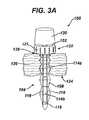
- FIG. 3Ais a partial cross-sectional view of one embodiment of an adjustable surgical access device having a cannula in the form of a retractable bellows shown in an insertion configuration;
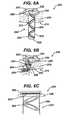
- FIG. 3Bis a partial cross-sectional view of the device of FIG. 3A showing an obturator being removed;
- FIG. 3Cis a partial cross-sectional view of the device of FIG. 3A showing the cannula in a deployed configuration
- FIG. 4Ais a partial cross-sectional view of another embodiment of an adjustable surgical access device shown in an insertion configuration
- FIG. 4Bis a partial cross-sectional view of the device of FIG. 4A shown in a deployed configuration
- FIG. 5Ais a perspective view of an embodiment of an adjustable surgical access device having a wire shown in an insertion configuration
- FIG. 5Bis a perspective view of the device of FIG. 5A showing the wire in a deployed configuration
- FIG. 5Cis a top view of multiple wire embodiments usable with the device of FIG. 5A ;
- FIG. 6Ais a partial cross-sectional view of another embodiment of an adjustable surgical access device having a flexible cannula with multiple stability rings shown in an insertion configuration;
- FIG. 6Bis a partial cross-sectional view of the device of FIG. 6A showing the cannula in a deployed configuration
- FIG. 6Cis a cross-sectional view of the device of FIG. 6A showing an actuator
- FIG. 7Ais a side view of one embodiment of an adjustable surgical access device having an obturator disposed therein for mounting a flexible cannula of the device in an insertion configuration;
- FIG. 7Bis a side view of the device of FIG. 7A showing the flexible cannula in which the obturator has released the flexible cannula;
- FIG. 7Cis a partial cross-sectional view of the device of FIG. 7A in a deployed configuration
- FIG. 7Dis a perspective view of an actuator of the device of FIG. 7A ;
- FIG. 7Eis a partial cross-sectional view of the actuator of FIG. 7D .
- an adjustable access devicecan include a housing having a cannula extending distally therefrom.
- the housing and the cannulacan define a working channel extending therethrough for receiving surgical instruments.
- the adjustable access devicecan further include at least one seal disposed within the working channel and configured to form at least one of a seal around an instrument disposed through the working channel and a seal when no instrument is disposed through the working channel.
- An actuatorcan be rotatably disposed on or in the housing such that rotation of the actuator relative to the housing is effective to move the cannula between an insertion configuration in which the cannula has a reduced profile enabling it to easily be inserted into a tissue opening, and an expanded configuration enabling the cannula to form an anchor against and/or within the tissue opening.
- the adjustable access devicecan allow for ease of insertion into an opening in tissue.
- An exemplary cannula of the surgical access devicecan have a reduced profile in an insertion configuration so that it can be inserted into a smaller tissue opening.
- a smaller tissue openingcan improve recovery time and cosmetic outcome of a procedure.
- the cannula of the adjustable access devicecan be moved to a deployed configuration that can provide active retraction of the tissue opening to help anchor the device within the tissue. Such anchoring can help form a better seal between the tissue and the device and help retain the device in a more stable position within the tissue.
- the cannula of the surgical access devicecan be returned to its reduced profile insertion configuration to enable easy removal from the tissue opening.
- the various surgical access devices described hereincan generally be configured to allow one or more surgical instruments to be inserted through one or more independent sealing ports or access ports formed in a housing of the device and into a body cavity.
- the sealing portscan each define working channels extending through the housing and in communication with a cannula extending distally from the housing.
- the cannulacan be configured as a wound protector, retractor, or other member for forming a pathway through tissue.
- the cannulacan generally be configured to be positioned within any opening in a patient's body, including a natural opening or an incision. The elasticity of the skin of the patient can assist in the retention of the cannula in the body opening or incision made in the body.
- the cannulacan be substantially flexible so that it can be easily maneuvered into and within tissue as needed.
- the cannulacan be substantially rigid or substantially semi-rigid and adjustable or expandable in shape/size.
- the cannulacan be formed of any suitable material known in the art, e.g., silicone, urethane, thermoplastic elastomer, and rubber.
- any and all of the surgical access devices described hereincan also include various other features, such as one or more ventilation ports to allow evacuation of smoke during procedures that utilize cautery, and/or one or more insufflation ports through which the surgeon can insufflate the abdomen to cause pneumoperitenium, as described by way of non-limiting example in U.S. Patent Application No. 2006/0247673 entitled “Multi-port Laparoscopic Access Device” filed Nov. 2, 2006, which is hereby incorporated by reference in its entirety.
- the insufflation portcan be located anywhere on the device, can have any size, and can accept a leur lock or a needle, as will be appreciated by those skilled in the art.
- a surgical access devicecan also include one or more safety shields positioned through, in, and around any of the components and/or tissue to protect the components against puncture or tear by surgical instruments being inserted through the device.
- safety shieldsare described in more detail in U.S. Patent Publication No. 2006/0247673 entitled “Multi-port Laparoscopic Access Device” filed Nov. 2, 2006, U.S. patent application Ser. No. 12/399,625 entitled “Methods and Devices for Providing Access to a Body Cavity” filed on Mar. 6, 2009, U.S. patent application Ser. No. 12/399,482 entitled “Methods and Devices for Providing Access to a Body Cavity” filed on Mar. 6, 2009, and U.S. patent application Ser. No. 12/242,765 entitled “Surgical Access Device” filed on Sep. 30, 2008, which are hereby incorporated by reference in their entireties.
- an engagement and/or release mechanismcan be included to allow certain components of the surgical access device to be removable as needed.
- Any engagement and release mechanism known in the arte.g., a snap-lock mechanism, corresponding threads, etc., can be used to releasably mate components of the device.
- Exemplary embodiments of engagement and release mechanismsare described in more detail in previously mentioned U.S. patent application Ser. No. 12/242,765 entitled “Surgical Access Device” filed on Sep. 30, 2008, U.S. patent application Ser. No. 12/399,625 entitled “Methods and Devices for Providing Access to a Body Cavity” filed on Mar. 6, 2009, and U.S. patent application Ser. No.
- most surgical access devicestypically include at least one seal disposed therein to prevent air and/or gas from escaping when surgical instruments are inserted therethrough.
- the surgical access devicecan include at least one instrument seal that forms a seal around an instrument disposed therethrough, but otherwise does not form a seal when no instrument is disposed therethrough; at least one channel seal or zero-closure seal that seals the working channel created by the sealing port when no instrument is disposed therethrough; or a combination instrument seal and channel seal that is effective to both form a seal around an instrument disposed therethrough and to form a seal in the working channel when no instrument is disposed therethrough.
- seals known in the artcan be used including, e.g., duckbill seals, cone seals, flapper valves, gel seals, diaphragm seals, lip seals, iris seals, etc.
- any combination of sealscan be included in any of the embodiments described herein, whether or not the seal combinations are specifically discussed in the corresponding description of a particular embodiment.
- Exemplary embodiments of various seal protectorsare described in more detail in U.S. Pat. No. 5,342,315 entitled “Trocar Seal/Protector Assemblies,” issued Aug. 30, 1994 and U.S. Pat. No. 7,163,525 entitled “Duckbill Seal Protector,” issued Jan. 16, 2007, which are hereby incorporated by reference in their entireties.
- FIGS. 1A and 1Billustrate one embodiment of a surgical access device 10 having a housing 12 configured to have one or more surgical instruments inserted therethrough.
- the housing 12can be fixedly or removably coupled to a cannula 14 that extends distally from the housing 12 to provide a pathway through tissue into a body cavity.
- the housing 12can be in a fixed position relative to the cannula 14 as shown in this embodiment, or the housing 12 can be movable relative to the cannula 14 .
- Exemplary embodiments of various housingsare described in more detail in previously mentioned U.S. Patent Publication No. 2006/0247673 entitled “Multi-port Laparoscopic Access Device” filed Nov. 2, 2006, U.S. patent application Ser. No.
- sealing ports 16 a , 16 b , 16 cextend through the housing 12 .
- the sealing ports 16 a , 16 b 16 ceach have a central axis that extends substantially parallel with a central longitudinal axis of the housing 12 , but any one or more of the sealing ports 16 a , 16 b , 16 c can be angled relative to the housing 12 and/or rotatable or otherwise movable relative to the housing 12 .
- any one or more of the sealing ports 16 a , 16 b , 16 ccan be configured to be movable relative to any one or more portions of the cannula 14 and/or any others of the sealing ports 16 a , 16 b , 16 c .
- Each sealing port, or any other portion of the housing or cannulacan include one or more sealing elements.
- a sealing elementcan include an instrument seal, a channel seal, and/or a combination instrument/channel seal as previously discussed herein.
- any configuration and any number of sealing portscan be used in any of the housing and cannula embodiments disclosed herein. Exemplary embodiments of various sealing ports are described in more detail in previously mentioned U.S. Patent Publication No.
- the cannula 14can have any configuration known in the art, in the illustrated embodiment, the cannula 14 is in the shape of a cylindrical elongate member having a proximal end 20 and a substantially constant outer diameter that terminates in a conical distal tip 18 , however the distal end 18 can have any configuration, including cylindrical.
- the distal end 18can have an opening 19 formed therein for receiving an obturator or other tissue penetrating tool, as well as surgical instruments inserted through the device 10 .
- a length of the cannula 14is generally greater than a diameter of the cannula 14 , although it will be appreciated that in some embodiments, the diameter of the cannula 14 could possibly be greater than its length.
- the cannula 14can be formed of an elastic and/or flexible band 22 that is wound into the shape of a helix, spring, and/or spiral.
- Helical coils 23 of the flexible band 22can define a lumen of the cannula 14 .
- the helical coils 23can each be mated to adjacent coils 23 such that there is no space between the coils 23 , or alternatively, a sheath or other connecting element can be disposed within and/or around the coils 23 to mate the coils 23 and prevent fluid flow therebetween.
- each coil 23can have one of a male and female rail and/or track formed on each proximal and distal end that is configured to mate with a corresponding male or female track on an adjacent coil 23 .
- the coils 23can interlock together.
- each coilcan have interlocking end portions 27 similar to a zip lock connection that secures the coils together.
- a proximal-most end of the flexible band 22 of the cannula 14can be coupled to an actuator 26 positioned within the housing 12 .
- the actuator 26can take any form known in the art, but in one exemplary embodiment, the actuator 26 can have an external portion 28 that can be gripped by a user to facilitate rotation.
- the actuator 26can further include an internal circular wheel 29 that is coupled to the external portion 28 and that can be rotated in either direction relative to the housing 12 and relative to the cannula 14 via the external portion 28 .
- the proximal-most end of the flexible band 22can be attached to and/or wound around the circular wheel such that rotation of the actuator 26 in a first direction is effective to wind the flexible band 22 around the circular wheel.
- first and second directionsare generally opposite directions and can be either clockwise or counter-clockwise as needed. In the illustrated embodiment, the first direction is clockwise and the second direction is counter-clockwise.
- Rotation of the actuator 26 in the first directioncan wind the flexible band 22 around the circular wheel, thereby tightening the helical cannula 14 into an insertion configuration. Because the coils 23 are interlocked together as described above, tightening of the flexible band 22 causes the helical cannula 14 to decrease in diameter and thus increase in length to facilitate easier insertion of the cannula 14 into a tissue opening. Rotation of the actuator 26 in the second direction can unwind the flexible band 22 from around the circular wheel, thereby causing the helical cannula 14 to increase in diameter and decrease in length into an anchoring and/or deployed configuration.
- the deployed configurationcan cause the cannula 14 to press against the tissue and can allow the cannula 14 to act as an anchor against tissue within the opening to stabilize the access device 10 .
- the cannula 14can act as a distal anchor within the tissue and the housing 12 can act as a proximal anchor on the surface of the tissue to stabilize the device 10 on both sides of the tissue. Due to the nature of the flexible band 22 having an expanded diameter in the deployed configuration, a biasing spring force can be created between the cannula 14 and the housing 12 , thereby providing stabilization for the device.
- the cannula 14can be biased to the deployed configuration and/or to the insertion configuration.
- the device 10can include a latch mechanism or other locking feature to lock the cannula 14 in either of the deployed and insertion configurations.
- the cannula 14can also be formed of a material that can cause the cannula 14 to be biased to one or other of the deployed and insertion configurations and/or to return to the deployed or insertion configuration under specific conditions.
- the actuator 26 of the surgical access device 10can be rotated in the first direction to move the cannula 14 to the insertion configuration in which the cannula 14 increases in length and decreases in diameter.
- the cannula 14can then be inserted into an opening in a patient through which a surgical procedure is to be performed.
- the actuator 26can be rotated in the second direction to cause the cannula 14 to decrease in length and increase in diameter.
- the cannula 14can increase in diameter until it contacts and applies nominal pressure against sidewalls of the tissue opening. In this way, the cannula 14 can act as both an anchor within the tissue opening and a working channel through the tissue opening through which a procedure can be performed.
- the actuator 26can once again be rotated in the first direction to wind the flexible band 22 around the circular wheel of the actuator 26 .
- the decreasing diameter of the cannula 14causes the cannula 14 to disengage from the tissue opening.
- the surgical access device 10can then be removed from the tissue opening.
- an adjustable surgical access device 50having a housing 52 with a cannula 54 extending therefrom.
- An insertion configuration of the surgical access device 50is shown in FIG. 2A
- a deployed configurationis shown in FIG. 2B .
- the housing 52 of the surgical access device 50can include any number of sealing ports as needed, for example, two, three, four, etc., but in the illustrated embodiment, the housing has a single sealing port 56 extending therethrough with a central longitudinal axis aligned with a central longitudinal axis of the surgical access device 50 .
- the cannula 54can have many configurations, but in the illustrated embodiment, the cannula 54 is formed from a plurality of flexible fibers 62 woven into a mesh material.
- the individual fibers 62can be formed from any material, including, but not limited to polypropylene, polyethylene, nylon and/or liquid crystal polymer. These fibers 62 can be woven into a mesh material and, in some embodiments, can be disposed within and/or around a flexible sheath or other protective covering to prevent instruments from snagging on the mesh when they are inserted through the cannula 54 .
- the cannula 54can be moved between the insertion configuration and the deployed configuration. As shown in the insertion configuration in FIG. 2A , the cannula 54 can be elongate and can have a distal rim 64 that is inverted radially outward from the cannula 54 . In other embodiments, the cannula 54 can be an elongate cylinder without an inverted distal rim 64 in the insertion configuration. In some embodiments, the cannula 54 can initially be telescoped within the housing 52 in the insertion configuration.
- the cannula 54can be telescoped out of the housing 52 by the obturator and into its elongate form shown in FIG. 2A .
- the cannula 54can be retroflexed radially outward, as shown in FIG. 2B , such that the retroflexed distal portion of the cannula 54 has a diameter D 1 substantially greater than the a diameter D 2 of the proximal portion of the cannula 54 , and greater than a maximum diameter D 3 of the distal rim 64 in the insertion configuration.
- a proximal end of the cannula 54can be coupled to an actuator 60 disposed on the housing 52 .
- Rotation of the actuator 60can be effective to move the cannula 54 between the insertion and deployed configurations. For example, since the distal end 66 of the cannula 54 is flipped radially outward, rotation of the actuator 60 in a first direction can cause the cannula 54 to continue to retroflex outward and upward as it moves to the deployed configuration.
- the cannula 54can be formed from a plurality of fibers 62 . Shortening some fibers 62 while leaving other fibers 62 loose at their original length can cause the cannula 54 to roll outward at the distal end.
- a first group of fibers 62can be attached to the actuator 60 , while a second group of fibers 62 are not.
- every third, fourth, fifth, etc. fiber 62 in the mesh materialcan be attached to the actuator 60 such that when the actuator 60 is rotated in the first direction, only those fibers 62 that are attached to the actuator 60 will rotate with the actuator 60 and thereby be tightened and shortened.
- the shortening of the first group of fibers 62 while the second group of fibers 62 remain their original lengthwill cause the cannula 54 to retroflex radially outward and upward (i.e., proximally).
- Rotation of the actuator 60 in a second directioncan lengthen the first group of fibers 62 coupled to the actuator 60 and thereby cause the cannula 54 to relax back to its elongate shape in the insertion configuration.
- the first and second directionscan generally be in opposite directions and can each be clockwise or counter-clockwise as needed.
- the first directionis in the counter-clockwise direction as shown in FIG. 2A
- the second directionis in the clockwise direction.
- the actuator 60When the actuator 60 is rotated to cause the cannula 54 to retroflex radially outward and upward, the distal rim 64 of the cannula 54 can act as an anchor against an inner surface 68 of tissue 70 to assist in stabilizing the access device 50 .
- the actuator 60can have a tightening assembly, for example, a ratchet style slip-clutch tightening assembly 74 , that prevents the cannula 54 from overstressing the inner surface 68 of the tissue 70 as the cannula is inverted.
- the slip clutch assembly 74can have detents that resist inadvertent dilation or uncoiling of the mechanism.
- the detentsact as a resting location to hold the housing head in its desired rotation, and due to a mechanical disadvantage, forces on the cannula cannot reverse the actuator 60 .
- the slip-clutch or other protection mechanismprevents further tightening of the first group of fibers 62 , and thereby prevents the distal rim 64 of the cannula 54 from pressing harder against the tissue 70 .
- the distal end 66 of the cannula 54can act as an anchor to stabilize the device.
- the housing 52can act as a proximal anchor while the distal end of the cannula 54 acts a distal anchor to further stabilize the device 50 .
- the surgical access device 50can be inserted into a tissue opening 72 using, for example, an obturator 76 .
- the actuator 60can be rotated in the first direction to cause the cannula 54 to retroflex radially outward and upward into engagement with the inner surface 68 of the tissue 70 .
- the cannula 54acts as both an anchor within the tissue opening 72 and a working channel through the tissue opening 72 through which a procedure can be performed.
- the actuator 60can be rotated in the second direction to release the first group of fibers 62 of the cannula 54 , allowing the cannula 54 to return to its elongate configuration.
- the surgical access device 50can then be removed from the tissue opening 72 .
- a surgical access device 100having a housing 102 with a cannula 104 extending therefrom.
- the housing 102can include any number of sealing ports as needed, for example, two, three, four, etc., but in the illustrated embodiment, the housing 102 can include a single sealing port 106 extending therethrough with a central longitudinal axis aligned with a central longitudinal axis of the surgical access device 100 .
- the cannula 104can include retractable bellows 108 that can be expanded and retracted as need for insertion and anchoring.
- the bellows 108can have foldable walls that can fold together in response to retraction.
- the folds in the bellows 108can be equally spaced and/or can be spaced further apart at a distal end of the bellows 108 .
- a proximal end of the cannula 104can have a radial lip 110 , shown in FIG. 3C , that can slidably mate with a distal end 112 of the housing 102 such that the housing 102 can be rotated relative to the cannula 104 without causing rotation of the cannula 104 .
- Any mating technique known in the artcan be used, but in one exemplary embodiment, there can be a slidable interference fit between the radial lip 110 and the distal end 112 of the housing 102 .
- the cannula 104can also include a set of telescoping inner tubes 114 a , 114 b disposed inside the retractable bellows 108 .
- the telescoping inner tubes 114 a , 114 bcan be arranged vertically inside the retractable bellows 108 , one on top of the other, such that a distal tube 114 b moves inside a proximal tube 114 a when the bellows 108 are retracted in a proximal direction toward the housing.
- the tubes 114 a , 114 bcan be joined by, for example, a sliding joint or they can be threaded together at a distal end of the proximal tube 114 a and a proximal end of the distal tube 114 b .
- the set of telescoping tubes 114 a , 114 bcan provide a smooth cylindrical working channel through the cannula 104 for surgical instruments even when the bellows 108 are retracted, as shown in FIG. 3C .
- One or more tension cablescan extend proximally from opposed sides of a distal end ring 118 of the cannula 104 to an actuator 120 disposed within the housing 102 .
- the cables 116can be positioned between the bellows 108 and the inner telescoping tubes 114 a , 114 b , although they can also be positioned outside of the bellows 108 or inside of the telescoping tubes 114 a , 114 b .
- a proximal end of the cables 116can be coupled to a circular wheel 122 of the actuator 120 such that rotation of an external portion 123 of the actuator 120 in a first direction can wind the cables 116 around the circular wheel 122 .
- a proximal portion of the bellows 108 that is disposed within tissue 126can collapse more easily than the bellows portion outside of the tissue and thus can be caused to expand outward into engagement with a tissue opening 128 .
- a distal portion of the bellows 108 not disposed within the tissue 126can be pulled against an inner surface 124 of the tissue 122 and can anchor against the tissue 126 to help stabilize the access device 100 .
- Rotation of the actuator 120 in a second directioncan unwind the cables 116 from the circular wheel 122 of the actuator 120 , thereby lengthening the cables 116 and causing the bellows 108 to unfold from their collapsed configuration.
- the first and second directionscan generally be in opposite directions and can each be clockwise or counter-clockwise as needed.
- the first directionis in the clockwise direction as shown in FIG. 3C
- the second directionis in the counter-clockwise direction.
- the surgical access device 100can be inserted into the opening 128 in a patient, e.g., using an obturator 130 , as shown in FIGS. 3A and 3B .
- the retractable bellows 108can be in an extended reduced diameter configuration during insertion.
- the actuator 120can be rotated in the first direction to wind the tension cables 116 around the circular wheel 122 . Rotation of the actuator 120 is effective to pull the distal end ring 118 of the bellows 108 proximally, causing the bellows 108 to collapse and retract against the tissue surface 124 , thereby expanding the size of the opening through the tissue.
- the distal telescoping tube 114 bcan retract inside the proximal telescoping tube 114 a providing a smooth working channel through which a surgical procedure can be performed.
- the retracted bellows 108can engage an inner surface of the tissue and can act as an anchor against the tissue to stabilize the access device 100 .
- the actuator 120can be rotated in the second direction to unwind the tension cables 116 . This causes the tension cables 116 to lengthen, thereby releasing the retractable bellows 108 back to an insertion configuration so that the surgical access device 100 can be removed from the tissue opening 128 .
- FIGS. 4A and 4BAnother embodiment of a surgical access device is illustrated in FIGS. 4A and 4B .
- a surgical access device 150is provided having a housing 152 with a deployment shaft 154 extending therefrom.
- the housing 152can include any number of sealing ports as needed, for example, two, three, four, etc., but in the illustrated embodiment, the housing 152 has a single sealing port 156 extending therethrough with a central longitudinal axis aligned with a central longitudinal axis of the surgical access device 150 .
- the surgical access device 150can also include a housing base 158 having a cannula 160 extending therefrom.
- the cannula 160can include a mesh anchor 162 coupled to a distal end 164 thereof for providing stabilization of the surgical access device 150 .
- the mesh anchor 162can be disposed inside the cannula 160 during insertion of the cannula 160 into a tissue opening 166 . Once the cannula 160 is in position within the tissue opening 166 , the deployment shaft 154 can be inserted into the cannula 160 to push the mesh anchor 162 out of the cannula 160 . Once the mesh anchor 162 is deployed from the cannula 160 , it can expand radially outward from the distal end 164 of the cannula 160 and retroflex proximally against an inner surface 168 of tissue 170 to provide stabilization for the access device 150 .
- the housing 152can sit flush against the housing base 158 , and the deployment device 154 can be positioned within the cannula 160 to provide a working channel through the device 150 through which instruments can be inserted.
- the mesh anchor 162can be formed of any suitable material known in the art, including, but not limited to, an elastic material or a shape memory material such as nitinol, and/or other materials such as polypropoleye, polyetholene, nylon, sanoprene, isoplast, isoprene, etc.
- a surgical access device 200having a cannula 204 with a housing base 202 .
- the access device 200can have one or more deployable anchors that can provide anchoring for the access device 200 .
- the access device 200can include one or more flexible wires 206 that can extend through eye hooks 208 or other restraining mechanisms along a sidewall 210 of the cannula 204 .
- the wire 206can extend from a proximal end 212 of the cannula 204 to a distal end 214 of the cannula in an insertion configuration, as shown in FIG. 5 A.
- the wire 206can be pushed through the eye hook 208 to cause the wire 206 to extend radially outward from the cannula 204 at the distal end 214 of the cannula 204 .
- two wires 208can be used to provide two “lobes” extending radially outward from the distal end of the cannula. The lobes can rest against an inner surface 218 of tissue 220 and provide stabilization for the device 200 .
- three, four, or more wires 208can be used to extend radially outward from the cannula 204 as shown in FIG. 5C , providing additional stabilization. Once a surgical procedure is complete, the wires 208 can be pulled proximally through the eye hook 208 so that the device 200 can be removed from the opening 216 .
- a surgical access device 250having a housing 252 with a cannula 254 extending therefrom.
- the housing 252can include any number of sealing ports as needed, for example, two, three, four, etc., but in the illustrated embodiment, the housing 252 has a single sealing port 256 extending therethrough with a central longitudinal axis aligned with a central longitudinal axis of the surgical access device.
- the housing 252can be positioned on a housing base 258 and can include an actuator 260 formed therein for controlling movement of the cannula 254 , as will be described below.
- the actuator 260can rotate relative to the housing 252 , the housing base 258 , and the cannula 254 by means of a ratchet mechanism 262 .
- a bottom portion of the ratchet mechanism 262can be disposed on the housing base 258 and a top portion of the ratchet mechanism 262 can be disposed on the rotatable actuator 260 .
- the cannula 254can be formed of a flexible material, for example, polypropoleye, polyetholene, nylon, sanoprene, isoplast, isoprene, etc., and can include a plurality of stability rings 264 positioned inside the cannula 254 .
- the stability rings 264can be circular, substantially rigid structures that are positioned at angles, for example, 45 degree angles, within the cannula 254 when the cannula 254 is in an insertion (reduced diameter) configuration as shown in FIG. 6A .
- the stability rings 264can be positioned at any angle within the cannula 254 as needed, including from about 5 degrees to about 175 degrees.
- the stability rings 264can give structure to the flexible cannula 254 , causing it to maintain a cylindrical shape.
- the stability rings 264can be disposed on an inner surface of the cannula 254 .
- the cannula 254can include an inner sheath, and the stability rings 264 can be disposed between the flexible cannula 254 and the inner sheath.
- the stability rings 264can be connected by a suture 266 that extends from a distal end 268 of the cannula 254 up through the actuator 260 .
- Each stability ring 264can be connected to the suture 266 on one side thereof, as shown in FIGS. 6A and 6B , or alternatively can be connected to one or more sutures at various locations.
- the suture 266can be wrapped around the actuator 260 causing the suture 266 in the cannula 254 to shorten and to pull up on the distal end 268 of the cannula 254 .
- the stability rings 264can collapse together, and the flexible cannula 254 can expand outward until tissue 270 is engaged, thereby increasing the size of the opening through the tissue.
- the access device 250can be inserted into a tissue opening 272 in the insertion configuration as shown in FIG. 6A .
- the actuator 260can be rotated in a first direction to wind the suture 266 up around the actuator 260 and shorten its length. This causes the suture 266 to pull up on the distal end 268 of the cannula 254 , collapsing the flexible cannula 254 and the stability rings 264 against an inner surface 274 of the tissue 270 . This anchors the cannula 254 against the tissue 270 , providing stability to the access device 250 .
- a slip clutch ratchet mechanismcan prevent the actuator 260 from over tightening the cannula 254 against the tissue 270 .
- the flexible cannula 254 and the stability rings 264can bulge outward so that a smooth interior surface is maintained through which an instrument can be inserted during a surgical procedure.
- the actuator 260can be rotated in a second direction to unwind the suture 266 and to relax the flexible cannula 254 .
- other release mechanismscan be used such as a button on the actuator 260 that releases the suture 266 or a pull tab on the actuator 260 that releases the suture 266 .
- first and second directionscan generally be in opposite directions and can each be clockwise or counter-clockwise as needed.
- first directionis in the counter-clockwise direction as shown in FIG. 6B
- second directionis in the clockwise direction.
- a surgical access device 300having a housing base 302 , an actuator 304 , and a cannula 306 extending from the housing base 302 . While a housing is not shown, it will be appreciated by those skilled in the art that any housing known in the art can be used with the surgical access device 300 .
- the cannula 306can be formed of a flexible material, for example, polypropoleye, polyetholene, nylon, sanoprene, isoplast, isoprene, etc., and can couple to the housing base 302 by any mating mechanism known in the art, including, but not limited to, adhesive, interference fit, fasteners, etc.
- a distal end 310 of the cannula 306can include a flexible retention ring 308 disposed therein.
- the retention ring 308can have a diameter in the deployed configuration that is greater than a diameter of the flexible cannula 306 such that the distal end 310 of the cannula 306 can flare radially outward toward the retention ring 308 .
- the access device 300can include an obturator 322 for inserting the access device 300 into a tissue opening 324 and for retaining the cannula 306 in an insertion configuration.
- the obturator 322can include an elongate body 332 having a sharp tissue penetrating distal end 326 and a rotatable head 328 on its proximal end. Since the retention ring 308 has a diameter greater than a diameter of the cannula 312 , insertion into the tissue opening 324 can be hindered by the larger retention ring 308 .
- the obturator 322can include one or more latches 330 disposed near its distal end 326 that extend radially outward from the elongate body 332 for retaining the retention ring 308 of the cannula 306 .
- the latches 330hold the retention ring 308 against the body of the obturator 322 such that the radius of the cannula 306 remains constant during insertion.
- a mechanical or electrical coupling mechanismcan be disposed within the obturator 322 between the latches 330 and the rotatable head 328 .
- the rotatable head 328 of the obturator 322can be rotated in a first direction to actuate the electrical or mechanical coupling mechanism to cause the latches 330 to retract inside the elongate body 332 and release the retention ring 308 of the cannula 306 .
- the cannula 306can also include one or more sutures 312 extending from the retention ring 308 to the actuator 304 .
- the suture 312can be embedded in a sidewall of the flexible cannula 306 .
- the actuator 304is rotated, the suture 312 is wound around a circular wheel 314 in the actuator 304 , causing the suture 312 to shorten.
- the shortening of the suture 312pulls up on the retention ring 308 causing the flexible cannula 306 to collapse and pull the ring 308 up toward the housing base 302 until it is secure against an inner surface 316 of the tissue 318 .
- the collapsed portion of the cannula 306can act as an anchor for the access device 300 , providing stability thereto.
- a pull tab 320 extending from the housing base 302can be connected to the actuator 304 such that pulling on the tab 320 releases the suture 312 , thereby relaxing the cannula 306 back to an insertion configuration.
- the surgical access device 300can be inserted into the tissue opening 324 using the obturator 322 .
- the obturator 322can be disposed inside the cannula 306 and the latches 330 on the obturator 322 can retain the retention ring 308 of the cannula 306 , as shown in FIG. 7A .
- the rotatable head 328 of the obturator 322can be rotated to cause the latches 330 to retract inside the obturator 322 , thereby releasing the retention ring 308 , as shown in FIG. 7B .
- the obturator 322can then be removed from the flexible cannula 306 .
- the actuator 304can be rotated in a first direction to tighten the suture 312 and pull up on the retention ring 308 of the cannula 306 . This can cause the cannula 306 to collapse and pull the ring 308 against the inner surface 316 of the tissue 318 .
- the tab 320can be pulled to release the suture 312 , thereby relaxing the cannula 306 and allowing it to return to its insertion configuration for removal from the tissue opening 324 .
- an exemplary surgical access device kitcould include multiple housings and seal bases with one or more cannulas.
- Various release mechanisms known in the artcan be used to releasably attach the various cannulas to a housing.
- a component of the devicesuch as a seal, housing, cannula, etc.
- a component of the devicecan have one or more lights formed thereon or around a circumference thereof to enable better visualization when inserted within a patient.
- any wavelength of lightcan be used for various applications, whether visible or invisible.
- Any number of portscan also be included on and/or through the surgical access devices to enable the use of various surgical techniques and devices as needed in a particular procedure.
- openings and portscan allow for the introduction of pressurized gases, vacuum systems, energy sources such as radiofrequency and ultrasound, irrigation, imaging, etc.
- any of these techniques and devicescan be removably attachable to the surgical access device and can be exchanged and manipulated as needed.
- any of the embodiments described hereincan be used in performing a sleeve gastrectomy and/or a gastroplasty, as described in U.S. application Ser. No. 12/242,765 entitled “Surgical Access Device” filed on Sep. 30, 2008; U.S. application Ser. No. 12/242,711 entitled “Surgical Access Device with Protective Element” filed on Sep. 30, 2008; U.S. application Ser. No. 12/242,721 entitled “Multiple Port Surgical Access Device” filed on Sep. 30, 2008; U.S. application Ser. No. 12/242,726 entitled “Variable Surgical Access Device” filed on Sep.
- the devices disclosed hereincan be designed to be disposed of after a single use, or they can be designed to be used multiple times. In either case, however, the device can be reconditioned for reuse after at least one use. Reconditioning can include any combination of the steps of disassembly of the device, followed by cleaning or replacement of particular pieces, and subsequent reassembly. In particular, the device can be disassembled, and any number of the particular pieces or parts of the device can be selectively replaced or removed in any combination, e.g., a seal, a housing, a cannula, etc.
- the devicecan be reassembled for subsequent use either at a reconditioning facility, or by a surgical team immediately prior to a surgical procedure.
- reconditioning of a devicecan utilize a variety of techniques for disassembly, cleaning/replacement, and reassembly. Use of such techniques, and the resulting reconditioned device, are all within the scope of the present application.
- the invention described hereinwill be processed before surgery.
- a new or used instrumentis obtained and if necessary cleaned.
- the instrumentcan then be sterilized.
- the instrumentis placed in a closed and sealed container, such as a plastic or TYVEK bag.
- the container and instrumentare then placed in a field of radiation that can penetrate the container, such as gamma radiation, x-rays, or high-energy electrons.
- the radiationkills bacteria on the instrument and in the container.
- the sterilized instrumentcan then be stored in the sterile container.
- the sealed containerkeeps the instrument sterile until it is opened in the medical facility.
- deviceis sterilized. This can be done by any number of ways known to those skilled in the art including beta or gamma radiation, ethylene oxide, steam, and a liquid bath (e.g., cold soak).
Landscapes
- Health & Medical Sciences (AREA)
- Surgery (AREA)
- Life Sciences & Earth Sciences (AREA)
- Biomedical Technology (AREA)
- Nuclear Medicine, Radiotherapy & Molecular Imaging (AREA)
- Engineering & Computer Science (AREA)
- Pathology (AREA)
- Heart & Thoracic Surgery (AREA)
- Medical Informatics (AREA)
- Molecular Biology (AREA)
- Animal Behavior & Ethology (AREA)
- General Health & Medical Sciences (AREA)
- Public Health (AREA)
- Veterinary Medicine (AREA)
- Surgical Instruments (AREA)
Abstract
Description
Claims (12)
Priority Applications (2)
| Application Number | Priority Date | Filing Date | Title |
|---|---|---|---|
| US12/635,762US8357088B2 (en) | 2009-12-11 | 2009-12-11 | Methods and devices for providing access into a body cavity |
| PCT/US2010/059629WO2011072100A2 (en) | 2009-12-11 | 2010-12-09 | Methods and devices for providing access into a body cavity |
Applications Claiming Priority (1)
| Application Number | Priority Date | Filing Date | Title |
|---|---|---|---|
| US12/635,762US8357088B2 (en) | 2009-12-11 | 2009-12-11 | Methods and devices for providing access into a body cavity |
Publications (2)
| Publication Number | Publication Date |
|---|---|
| US20110144448A1 US20110144448A1 (en) | 2011-06-16 |
| US8357088B2true US8357088B2 (en) | 2013-01-22 |
Family
ID=44143700
Family Applications (1)
| Application Number | Title | Priority Date | Filing Date |
|---|---|---|---|
| US12/635,762Active2030-10-11US8357088B2 (en) | 2009-12-11 | 2009-12-11 | Methods and devices for providing access into a body cavity |
Country Status (1)
| Country | Link |
|---|---|
| US (1) | US8357088B2 (en) |
Cited By (1)
| Publication number | Priority date | Publication date | Assignee | Title |
|---|---|---|---|---|
| US20160354113A1 (en)* | 2015-06-04 | 2016-12-08 | DePuy Synthes Products, Inc. | Surgical Cannula System and Method of Use |
Families Citing this family (23)
| Publication number | Priority date | Publication date | Assignee | Title |
|---|---|---|---|---|
| US8231570B2 (en) | 2009-12-11 | 2012-07-31 | Ethicon Endo-Surgery, Inc. | Inverted conical expandable retractor |
| US8282546B2 (en) | 2009-12-11 | 2012-10-09 | Ethicon Endo-Surgery, Inc. | Inverted conical expandable retractor with coil spring |
| US8414483B2 (en) | 2009-12-11 | 2013-04-09 | Ethicon Endo-Surgery, Inc. | Methods and devices for providing access into a body cavity |
| US8435174B2 (en) | 2009-12-11 | 2013-05-07 | Ethicon Endo-Surgery, Inc. | Methods and devices for accessing a body cavity |
| KR101082762B1 (en)* | 2011-02-18 | 2011-11-10 | 이정삼 | Laparoscopic Traction System |
| US20120245426A1 (en)* | 2011-03-25 | 2012-09-27 | Salvas Paul L | Adjustable cannula |
| US8496633B2 (en)* | 2011-08-25 | 2013-07-30 | Ethicon Endo-Surgery, Inc. | Surgical access device with adjustable cannula |
| US8491545B2 (en)* | 2011-08-25 | 2013-07-23 | Ethicon Endo-Surgery, Inc. | Surgical access device with adjustable cannula |
| US8486045B2 (en)* | 2011-08-25 | 2013-07-16 | Ethicon Endo-Surgery, Inc. | Surgical access device with adjustable cannula |
| US8496632B2 (en)* | 2011-08-25 | 2013-07-30 | Ethicon Endo-Surgery, Inc. | Surgical access device with adjustable cannula |
| US8439881B2 (en)* | 2011-08-25 | 2013-05-14 | Ethicon Endo-Surgery, Inc. | Surgical access device with adjustable cannula |
| US10646690B2 (en)* | 2012-11-20 | 2020-05-12 | University Of Massachusetts | Flexible surgical sheath and multi-part insertion cannula |
| JP6388914B2 (en)* | 2013-04-17 | 2018-09-12 | デピュイ・シンセス・プロダクツ・インコーポレイテッド | Extendable dilator |
| US9848879B2 (en)* | 2013-08-02 | 2017-12-26 | Covidien Lp | Devices, systems, and methods for wound closure |
| US9687413B2 (en) | 2014-02-18 | 2017-06-27 | Covidien Lp | Compression garment inflation |
| US9572595B1 (en)* | 2014-03-05 | 2017-02-21 | Northgate Technologies Inc. | In-dwelling port for access into a body |
| CN104983452B (en)* | 2015-05-22 | 2017-10-13 | 东莞麦可龙医疗科技有限公司 | The manufacture method and reducing abdominal cavity puncture outfit of reducing abdominal cavity puncture outfit |
| DE102015012964B4 (en)* | 2015-10-08 | 2018-12-27 | Karl Storz Se & Co. Kg | Access system for endoscopic operations |
| US10485582B2 (en)* | 2016-07-22 | 2019-11-26 | Intuitive Surgical Operations, Inc. | Cannulas having body wall retention features, and related systems and methods |
| US10722265B1 (en)* | 2016-09-09 | 2020-07-28 | Rebound Therapeutics Corporation | Expandable and collapsible brain cannula |
| JP6979525B2 (en)* | 2017-12-13 | 2021-12-15 | コンメッド コーポレーション | Lumbar Access Portal Saver |
| CA3096540A1 (en)* | 2018-04-11 | 2019-10-17 | Vadovations, Inc. | Tissue interface apparatus, systems, and methods |
| WO2021183268A1 (en)* | 2020-03-10 | 2021-09-16 | Boston Scientific Scimed, Inc. | Device, a system, and a method for access cannula advancement |
Citations (114)
| Publication number | Priority date | Publication date | Assignee | Title |
|---|---|---|---|---|
| US3397699A (en) | 1966-05-05 | 1968-08-20 | Gerald C. Kohl | Retaining catheter having resiliently biased wing flanges |
| US3924632A (en)* | 1972-12-07 | 1975-12-09 | William A Cook | Fiber glass reinforced catheter |
| US4022191A (en) | 1976-06-04 | 1977-05-10 | Khosrow Jamshidi | Biopsy needle guard and guide |
| US4608977A (en) | 1979-08-29 | 1986-09-02 | Brown Russell A | System using computed tomography as for selective body treatment |
| US4809694A (en) | 1987-05-19 | 1989-03-07 | Ferrara Vincent L | Biopsy guide |
| US5031634A (en) | 1990-01-19 | 1991-07-16 | Beth Israel Hospital Assoc., Inc. | Adjustable biopsy needle-guide device |
| US5053042A (en) | 1990-01-16 | 1991-10-01 | Bidwell Clifford D | Biopsy needle guide for use with CT scanner |
| US5100387A (en) | 1990-07-02 | 1992-03-31 | Ng Raymond C | Disposable universal needle guide apparatus (for amniocentesis) |
| US5201742A (en) | 1991-04-16 | 1993-04-13 | Hasson Harrith M | Support jig for a surgical instrument |
| US5235987A (en) | 1991-02-22 | 1993-08-17 | Dymax Corporation | Needle guide |
| US5257975A (en) | 1992-08-14 | 1993-11-02 | Edward Weck Incorporated | Cannula retention device |
| US5279564A (en)* | 1992-09-11 | 1994-01-18 | Edward Weck Incorporated | Cannula retention device |
| US5312417A (en) | 1992-07-29 | 1994-05-17 | Wilk Peter J | Laparoscopic cannula assembly and associated method |
| US5316014A (en) | 1992-02-07 | 1994-05-31 | Livingston Products, Inc. | Biopsy locator and guide |
| US5320111A (en) | 1992-02-07 | 1994-06-14 | Livingston Products, Inc. | Light beam locator and guide for a biopsy needle |
| US5330437A (en) | 1993-11-12 | 1994-07-19 | Ethicon Endo-Surgery | Self sealing flexible elastomeric valve and trocar assembly for incorporating same |
| US5342315A (en) | 1993-04-12 | 1994-08-30 | Ethicon, Inc. | Trocar seal/protector assemblies |
| US5431676A (en) | 1993-03-05 | 1995-07-11 | Innerdyne Medical, Inc. | Trocar system having expandable port |
| US5494039A (en) | 1993-07-16 | 1996-02-27 | Cryomedical Sciences, Inc. | Biopsy needle insertion guide and method of use in prostate cryosurgery |
| US5569205A (en) | 1994-07-14 | 1996-10-29 | Hart; Charles C. | Multiport trocar |
| WO1996036283A1 (en) | 1995-05-19 | 1996-11-21 | General Surgical Innovations, Inc. | Skin seal with inflatable membrane |
| US5628732A (en) | 1996-01-19 | 1997-05-13 | Ethicon Endo-Surgery, Inc. | Trocar with improved universal seal |
| US5647373A (en) | 1993-11-07 | 1997-07-15 | Ultra-Guide Ltd. | Articulated needle guide for ultrasound imaging and method of using same |
| US5707359A (en) | 1995-11-14 | 1998-01-13 | Bufalini; Bruno | Expanding trocar assembly |
| US5857999A (en) | 1995-05-05 | 1999-01-12 | Imagyn Medical Technologies, Inc. | Small diameter introducer for laparoscopic instruments |
| US5868673A (en) | 1995-03-28 | 1999-02-09 | Sonometrics Corporation | System for carrying out surgery, biopsy and ablation of a tumor or other physical anomaly |
| US5882340A (en) | 1992-04-15 | 1999-03-16 | Yoon; Inbae | Penetrating instrument having an expandable anchoring portion for triggering protrusion of a safety member and/or retraction of a penetrating member |
| US5911707A (en) | 1997-04-09 | 1999-06-15 | Datascope Investment Corp. | Needle guide |
| US5916175A (en) | 1996-01-26 | 1999-06-29 | Allegiance Corporation | Biopsy needle appliance and inserting guide with adjustable sample length and/or needle cutting stroke |
| US5941889A (en) | 1997-10-14 | 1999-08-24 | Civco Medical Instruments Inc. | Multiple angle disposable needle guide system |
| US5954670A (en) | 1994-10-05 | 1999-09-21 | Baker; Gary H. | Mandrel-guided tandem multiple channel biopsy guide device and method of use |
| US5984930A (en) | 1996-09-30 | 1999-11-16 | George S. Allen | Biopsy guide |
| US6017356A (en) | 1997-09-19 | 2000-01-25 | Ethicon Endo-Surgery Inc. | Method for using a trocar for penetration and skin incision |
| US6048321A (en) | 1997-10-10 | 2000-04-11 | William E. McPherson | Guide assembly for a biopsy device |
| USD422706S (en) | 1997-04-30 | 2000-04-11 | Surgical Navigation Technologies | Biopsy guide tube |
| WO2000041759A1 (en) | 1999-01-13 | 2000-07-20 | A-Med Systems, Inc. | Sealing cannula device |
| US6110182A (en) | 1998-06-22 | 2000-08-29 | Ohio Medical Instruments Company, Inc. | Target socket |
| WO2000062689A1 (en) | 1999-04-21 | 2000-10-26 | Bisgaard Therkel | A trocar with expandable point |
| US6162196A (en) | 1994-07-14 | 2000-12-19 | Applied Medical Resources Corporation | Multiport access device |
| WO2001008563A2 (en) | 1999-07-30 | 2001-02-08 | Gaya Limited | A surgical access device |
| US6195577B1 (en) | 1998-10-08 | 2001-02-27 | Regents Of The University Of Minnesota | Method and apparatus for positioning a device in a body |
| US6203499B1 (en) | 1998-10-05 | 2001-03-20 | Atl Ultrasound Inc. | Multiple angle needle guide |
| US6216029B1 (en) | 1995-07-16 | 2001-04-10 | Ultraguide Ltd. | Free-hand aiming of a needle guide |
| US6231565B1 (en) | 1997-06-18 | 2001-05-15 | United States Surgical Corporation | Robotic arm DLUs for performing surgical tasks |
| US6231585B1 (en) | 1997-11-20 | 2001-05-15 | Medivas, Llc | Device for stabilizing a treatment site and method of use |
| US6236875B1 (en) | 1994-10-07 | 2001-05-22 | Surgical Navigation Technologies | Surgical navigation systems including reference and localization frames |
| US6245028B1 (en) | 1999-11-24 | 2001-06-12 | Marconi Medical Systems, Inc. | Needle biopsy system |
| US6283942B1 (en) | 1997-12-30 | 2001-09-04 | Volunteers For Medical Engineering | Needle insertion guide apparatus and method |
| US6361499B1 (en) | 1998-09-16 | 2002-03-26 | Civco Medical Instruments Inc. | Multiple angle needle guide |
| US6379307B1 (en) | 1998-09-16 | 2002-04-30 | Roy Filly | Adjustable needle guide apparatus and method |
| US6400979B1 (en) | 1997-02-20 | 2002-06-04 | Johns Hopkins University | Friction transmission with axial loading and a radiolucent surgical needle driver |
| US6443960B1 (en) | 2000-11-24 | 2002-09-03 | Neorad A/S | Apparatus for light beam guided biopsy |
| US6445943B1 (en) | 1994-09-15 | 2002-09-03 | Visualization Technology, Inc. | Position tracking and imaging system for use in medical applications |
| US6451042B1 (en)* | 1990-03-02 | 2002-09-17 | General Surgical Innovations, Inc. | Method and apparatus for dissecting tissue layers |
| US6468226B1 (en) | 2000-11-22 | 2002-10-22 | Mcintyre, Iv John J. | Remote tissue biopsy apparatus and associated methods |
| US6475152B1 (en) | 2000-03-13 | 2002-11-05 | Koninklijke Philips Electronics N.V. | Biopsy needle guide for attachment to an ultrasound transducer |
| US6501981B1 (en) | 1999-03-16 | 2002-12-31 | Accuray, Inc. | Apparatus and method for compensating for respiratory and patient motions during treatment |
| US6529765B1 (en) | 1998-04-21 | 2003-03-04 | Neutar L.L.C. | Instrumented and actuated guidance fixture for sterotactic surgery |
| US6535756B1 (en) | 2000-04-07 | 2003-03-18 | Surgical Navigation Technologies, Inc. | Trajectory storage apparatus and method for surgical navigation system |
| US6539121B1 (en) | 1997-02-14 | 2003-03-25 | At&T Corp. | Method and apparatus to prioritize video information during coding and decoding |
| US6546279B1 (en) | 2001-10-12 | 2003-04-08 | University Of Florida | Computer controlled guidance of a biopsy needle |
| US6547782B1 (en) | 1991-06-13 | 2003-04-15 | International Business Machines, Corp. | System and method for augmentation of surgery |
| US6551270B1 (en) | 2000-08-30 | 2003-04-22 | Snowden Pencer, Inc. | Dual lumen access port |
| US20030100814A1 (en) | 2001-11-23 | 2003-05-29 | Johann Kindlein | Self controlled image guided device and method for inserting a needle in an animal body for effecting radiation therapy in said body |
| US20030208207A1 (en) | 2002-05-02 | 2003-11-06 | Gmp Surgical Solutions, Inc. | Apparatus for positioning a medical instrument relative to a patient |
| US20030229338A1 (en) | 2000-11-03 | 2003-12-11 | Irion Klaus M. | Device for holding and positioning an endoscopic instrument |
| US6665554B1 (en) | 1998-11-18 | 2003-12-16 | Steve T. Charles | Medical manipulator for use with an imaging device |
| US6687531B1 (en) | 1994-09-15 | 2004-02-03 | Ge Medical Systems Global Technology Company, Llc | Position tracking and imaging system for use in medical applications |
| US6723106B1 (en) | 1998-11-23 | 2004-04-20 | Microdexterity Systems, Inc. | Surgical manipulator |
| US20040082969A1 (en) | 2002-10-23 | 2004-04-29 | Stephen Kerr | Laparoscopic direct vision dissecting port |
| US6731966B1 (en) | 1997-03-04 | 2004-05-04 | Zachary S. Spigelman | Systems and methods for targeting a lesion |
| US6752812B1 (en) | 1997-05-15 | 2004-06-22 | Regent Of The University Of Minnesota | Remote actuation of trajectory guide |
| US6770027B2 (en) | 2001-10-05 | 2004-08-03 | Scimed Life Systems, Inc. | Robotic endoscope with wireless interface |
| US6783524B2 (en) | 2001-04-19 | 2004-08-31 | Intuitive Surgical, Inc. | Robotic surgical tool with ultrasound cauterizing and cutting instrument |
| US6785572B2 (en) | 2001-11-21 | 2004-08-31 | Koninklijke Philips Electronics, N.V. | Tactile feedback and display in a CT image guided robotic system for interventional procedures |
| US20040185453A1 (en) | 2003-03-21 | 2004-09-23 | Joel Myerson | Affinity based methods for separating homologous parental genetic material and uses thereof |
| US6808492B2 (en) | 2002-08-16 | 2004-10-26 | Linvatec Corporation | Endoscopic cannula fixation system |
| US20040230161A1 (en) | 2003-03-21 | 2004-11-18 | Zeiner Mark S. | Trocar seal assembly |
| US20040254426A1 (en) | 2003-04-25 | 2004-12-16 | Thomas Wenchell | Surgical hand access apparatus |
| US6866655B2 (en)* | 2002-04-23 | 2005-03-15 | Scimed Life Systems, Inc. | Medical device with atraumatic tip |
| US20050222582A1 (en) | 2004-04-05 | 2005-10-06 | Thomas Wenchell | Surgical hand access apparatus |
| WO2005097234A2 (en) | 2004-04-05 | 2005-10-20 | Tyco Healthcare Group Lp | Surgical hand access apparatus |
| US7021173B2 (en) | 2002-02-06 | 2006-04-04 | The John Hopkins University | Remote center of motion robotic system and method |
| WO2006057982A2 (en) | 2004-11-24 | 2006-06-01 | Edrich Health Technologies, Inc. | Gel based laparoscopic trocar |
| US20060149137A1 (en) | 2005-01-05 | 2006-07-06 | Applied Medical Resources Corporation | Easily placeable and removable wound retractor |
| US20060161049A1 (en) | 1997-04-30 | 2006-07-20 | Richard Beane | Surgical access port |
| US7083626B2 (en) | 2002-10-04 | 2006-08-01 | Applied Medical Resources Corporation | Surgical access device with pendent valve |
| US20060247673A1 (en)* | 2005-04-08 | 2006-11-02 | Voegele James W | Multi-port laparoscopic access device |
| US20060247499A1 (en) | 1998-12-01 | 2006-11-02 | John Butler | Apparatus for inserting a surgical device at least partially through a wond opening |
| WO2006117819A1 (en) | 2005-04-29 | 2006-11-09 | Elenor S.R.L. | Radially expandable anchorage guide for trocars |
| US7163525B2 (en) | 2004-12-17 | 2007-01-16 | Ethicon Endo-Surgery, Inc. | Duckbill seal protector |
| US20070106319A1 (en) | 2005-11-09 | 2007-05-10 | Applied Medical Resources Corporation | Trocars with advanced fixation |
| US20070185453A1 (en) | 2003-03-21 | 2007-08-09 | Michael Cropper S | Conical trocar seal |
| US20070260273A1 (en) | 2006-05-08 | 2007-11-08 | Ethicon Endo-Surgery, Inc. | Endoscopic Translumenal Surgical Systems |
| US20070260121A1 (en) | 2006-05-08 | 2007-11-08 | Ethicon Endo-Surgery, Inc. | Endoscopic Translumenal Surgical Systems |
| WO2008027375A2 (en) | 2006-08-31 | 2008-03-06 | Cook Incorporated | Rotationally actuated fixation mechanism |
| US20080086167A1 (en) | 2006-10-06 | 2008-04-10 | Dominick Mastri | Elastically deformable surgical access device |
| US20080086080A1 (en) | 2006-10-06 | 2008-04-10 | Surgiquest, Incorporated | Elastically deformable surgical access device having telescoping guide tube |
| US7371227B2 (en) | 2004-12-17 | 2008-05-13 | Ethicon Endo-Surgery, Inc. | Trocar seal assembly |
| US20080132946A1 (en)* | 2006-12-04 | 2008-06-05 | Gregory Paul Mueller | Skin port |
| US20080255519A1 (en) | 2007-03-30 | 2008-10-16 | Pnavel Systems, Inc. | Laparoscopic port assembly |
| US20090005799A1 (en) | 2007-06-29 | 2009-01-01 | Ethicon Endo-Surgery, Inc. | Duckbill seal with fluid drainage feature |
| US20090082731A1 (en) | 2007-09-20 | 2009-03-26 | Ethicon Endo-Surgery, Inc. | Dilating trocar cannula |
| US20090105659A1 (en) | 2007-10-17 | 2009-04-23 | Tyco Healthcare Group Lp | Anchoring cannula |
| US20100081882A1 (en) | 2008-09-30 | 2010-04-01 | Ethicon Endo-Surgery, Inc. | Multiple Port Surgical Access Device |
| US20100081863A1 (en) | 2008-09-30 | 2010-04-01 | Ethicon Endo-Surgery, Inc. | Methods and devices for performing gastrectomies and gastroplasties |
| US20100081881A1 (en) | 2008-09-30 | 2010-04-01 | Ethicon Endo-Surgery, Inc. | Surgical Access Device with Protective Element |
| US20100081880A1 (en) | 2008-09-30 | 2010-04-01 | Ethicon Endo-Surgery, Inc. | Surgical Access Device |
| US20100081995A1 (en) | 2008-09-30 | 2010-04-01 | Ethicon Endo-Surgery, Inc. | Variable Surgical Access Device |
| US20100081883A1 (en) | 2008-09-30 | 2010-04-01 | Ethicon Endo-Surgery, Inc. | Methods and devices for performing gastroplasties using a multiple port access device |
| US20100118830A1 (en) | 2008-11-10 | 2010-05-13 | Cisco Technology, Inc. | Mobile Intelligent Roaming Using Multi-Modal Access Point Devices |
| US20100280326A1 (en)* | 2009-05-04 | 2010-11-04 | Hess Christopher J | Surgical devices for internal access through tissue |
| US20110124967A1 (en) | 2009-11-20 | 2011-05-26 | Ethicon Endo-Surgery, Inc. | Discrete flexion head for single port device |
| US20110144442A1 (en) | 2009-12-11 | 2011-06-16 | Ethicon Endo-Surgery, Inc. | Methods and Devices for Providing Access into a Body Cavity |
- 2009
- 2009-12-11USUS12/635,762patent/US8357088B2/enactiveActive
Patent Citations (121)
| Publication number | Priority date | Publication date | Assignee | Title |
|---|---|---|---|---|
| US3397699A (en) | 1966-05-05 | 1968-08-20 | Gerald C. Kohl | Retaining catheter having resiliently biased wing flanges |
| US3924632A (en)* | 1972-12-07 | 1975-12-09 | William A Cook | Fiber glass reinforced catheter |
| US4022191A (en) | 1976-06-04 | 1977-05-10 | Khosrow Jamshidi | Biopsy needle guard and guide |
| US4608977A (en) | 1979-08-29 | 1986-09-02 | Brown Russell A | System using computed tomography as for selective body treatment |
| US4809694A (en) | 1987-05-19 | 1989-03-07 | Ferrara Vincent L | Biopsy guide |
| US5053042A (en) | 1990-01-16 | 1991-10-01 | Bidwell Clifford D | Biopsy needle guide for use with CT scanner |
| US5031634A (en) | 1990-01-19 | 1991-07-16 | Beth Israel Hospital Assoc., Inc. | Adjustable biopsy needle-guide device |
| US6451042B1 (en)* | 1990-03-02 | 2002-09-17 | General Surgical Innovations, Inc. | Method and apparatus for dissecting tissue layers |
| US5100387A (en) | 1990-07-02 | 1992-03-31 | Ng Raymond C | Disposable universal needle guide apparatus (for amniocentesis) |
| US6490467B1 (en) | 1990-10-19 | 2002-12-03 | Surgical Navigation Technologies, Inc. | Surgical navigation systems including reference and localization frames |
| US5235987A (en) | 1991-02-22 | 1993-08-17 | Dymax Corporation | Needle guide |
| US5201742A (en) | 1991-04-16 | 1993-04-13 | Hasson Harrith M | Support jig for a surgical instrument |
| US6547782B1 (en) | 1991-06-13 | 2003-04-15 | International Business Machines, Corp. | System and method for augmentation of surgery |
| US5316014A (en) | 1992-02-07 | 1994-05-31 | Livingston Products, Inc. | Biopsy locator and guide |
| US5320111A (en) | 1992-02-07 | 1994-06-14 | Livingston Products, Inc. | Light beam locator and guide for a biopsy needle |
| US5882340A (en) | 1992-04-15 | 1999-03-16 | Yoon; Inbae | Penetrating instrument having an expandable anchoring portion for triggering protrusion of a safety member and/or retraction of a penetrating member |
| US5312417A (en) | 1992-07-29 | 1994-05-17 | Wilk Peter J | Laparoscopic cannula assembly and associated method |
| US5257975A (en) | 1992-08-14 | 1993-11-02 | Edward Weck Incorporated | Cannula retention device |
| US5279564A (en)* | 1992-09-11 | 1994-01-18 | Edward Weck Incorporated | Cannula retention device |
| US5431676A (en) | 1993-03-05 | 1995-07-11 | Innerdyne Medical, Inc. | Trocar system having expandable port |
| US5342315A (en) | 1993-04-12 | 1994-08-30 | Ethicon, Inc. | Trocar seal/protector assemblies |
| US5494039A (en) | 1993-07-16 | 1996-02-27 | Cryomedical Sciences, Inc. | Biopsy needle insertion guide and method of use in prostate cryosurgery |
| US5647373A (en) | 1993-11-07 | 1997-07-15 | Ultra-Guide Ltd. | Articulated needle guide for ultrasound imaging and method of using same |
| US5330437A (en) | 1993-11-12 | 1994-07-19 | Ethicon Endo-Surgery | Self sealing flexible elastomeric valve and trocar assembly for incorporating same |
| US6162196A (en) | 1994-07-14 | 2000-12-19 | Applied Medical Resources Corporation | Multiport access device |
| US5569205A (en) | 1994-07-14 | 1996-10-29 | Hart; Charles C. | Multiport trocar |
| US6445943B1 (en) | 1994-09-15 | 2002-09-03 | Visualization Technology, Inc. | Position tracking and imaging system for use in medical applications |
| US6687531B1 (en) | 1994-09-15 | 2004-02-03 | Ge Medical Systems Global Technology Company, Llc | Position tracking and imaging system for use in medical applications |
| US5954670A (en) | 1994-10-05 | 1999-09-21 | Baker; Gary H. | Mandrel-guided tandem multiple channel biopsy guide device and method of use |
| US6236875B1 (en) | 1994-10-07 | 2001-05-22 | Surgical Navigation Technologies | Surgical navigation systems including reference and localization frames |
| US5868673A (en) | 1995-03-28 | 1999-02-09 | Sonometrics Corporation | System for carrying out surgery, biopsy and ablation of a tumor or other physical anomaly |
| US5857999A (en) | 1995-05-05 | 1999-01-12 | Imagyn Medical Technologies, Inc. | Small diameter introducer for laparoscopic instruments |
| WO1996036283A1 (en) | 1995-05-19 | 1996-11-21 | General Surgical Innovations, Inc. | Skin seal with inflatable membrane |
| US6216029B1 (en) | 1995-07-16 | 2001-04-10 | Ultraguide Ltd. | Free-hand aiming of a needle guide |
| US5707359A (en) | 1995-11-14 | 1998-01-13 | Bufalini; Bruno | Expanding trocar assembly |
| US5628732A (en) | 1996-01-19 | 1997-05-13 | Ethicon Endo-Surgery, Inc. | Trocar with improved universal seal |
| US5916175A (en) | 1996-01-26 | 1999-06-29 | Allegiance Corporation | Biopsy needle appliance and inserting guide with adjustable sample length and/or needle cutting stroke |
| US5984930A (en) | 1996-09-30 | 1999-11-16 | George S. Allen | Biopsy guide |
| US6539121B1 (en) | 1997-02-14 | 2003-03-25 | At&T Corp. | Method and apparatus to prioritize video information during coding and decoding |
| US7076106B2 (en) | 1997-02-14 | 2006-07-11 | Barin Geoffry Haskell | Video objects coded by keyregions |
| US6400979B1 (en) | 1997-02-20 | 2002-06-04 | Johns Hopkins University | Friction transmission with axial loading and a radiolucent surgical needle driver |
| US6731966B1 (en) | 1997-03-04 | 2004-05-04 | Zachary S. Spigelman | Systems and methods for targeting a lesion |
| US5911707A (en) | 1997-04-09 | 1999-06-15 | Datascope Investment Corp. | Needle guide |
| US20060161049A1 (en) | 1997-04-30 | 2006-07-20 | Richard Beane | Surgical access port |
| USD422706S (en) | 1997-04-30 | 2000-04-11 | Surgical Navigation Technologies | Biopsy guide tube |
| US6752812B1 (en) | 1997-05-15 | 2004-06-22 | Regent Of The University Of Minnesota | Remote actuation of trajectory guide |
| US6231565B1 (en) | 1997-06-18 | 2001-05-15 | United States Surgical Corporation | Robotic arm DLUs for performing surgical tasks |
| US6017356A (en) | 1997-09-19 | 2000-01-25 | Ethicon Endo-Surgery Inc. | Method for using a trocar for penetration and skin incision |
| US6048321A (en) | 1997-10-10 | 2000-04-11 | William E. McPherson | Guide assembly for a biopsy device |
| US5941889A (en) | 1997-10-14 | 1999-08-24 | Civco Medical Instruments Inc. | Multiple angle disposable needle guide system |
| US6231585B1 (en) | 1997-11-20 | 2001-05-15 | Medivas, Llc | Device for stabilizing a treatment site and method of use |
| US6283942B1 (en) | 1997-12-30 | 2001-09-04 | Volunteers For Medical Engineering | Needle insertion guide apparatus and method |
| US6529765B1 (en) | 1998-04-21 | 2003-03-04 | Neutar L.L.C. | Instrumented and actuated guidance fixture for sterotactic surgery |
| US6110182A (en) | 1998-06-22 | 2000-08-29 | Ohio Medical Instruments Company, Inc. | Target socket |
| US6361499B1 (en) | 1998-09-16 | 2002-03-26 | Civco Medical Instruments Inc. | Multiple angle needle guide |
| US6379307B1 (en) | 1998-09-16 | 2002-04-30 | Roy Filly | Adjustable needle guide apparatus and method |
| US6203499B1 (en) | 1998-10-05 | 2001-03-20 | Atl Ultrasound Inc. | Multiple angle needle guide |
| US6195577B1 (en) | 1998-10-08 | 2001-02-27 | Regents Of The University Of Minnesota | Method and apparatus for positioning a device in a body |
| US6782288B2 (en) | 1998-10-08 | 2004-08-24 | Regents Of The University Of Minnesota | Method and apparatus for positioning a device in a body |
| US6665554B1 (en) | 1998-11-18 | 2003-12-16 | Steve T. Charles | Medical manipulator for use with an imaging device |
| US6723106B1 (en) | 1998-11-23 | 2004-04-20 | Microdexterity Systems, Inc. | Surgical manipulator |
| US20060247499A1 (en) | 1998-12-01 | 2006-11-02 | John Butler | Apparatus for inserting a surgical device at least partially through a wond opening |
| WO2000041759A1 (en) | 1999-01-13 | 2000-07-20 | A-Med Systems, Inc. | Sealing cannula device |
| US6501981B1 (en) | 1999-03-16 | 2002-12-31 | Accuray, Inc. | Apparatus and method for compensating for respiratory and patient motions during treatment |
| WO2000062689A1 (en) | 1999-04-21 | 2000-10-26 | Bisgaard Therkel | A trocar with expandable point |
| WO2001008563A2 (en) | 1999-07-30 | 2001-02-08 | Gaya Limited | A surgical access device |
| US6245028B1 (en) | 1999-11-24 | 2001-06-12 | Marconi Medical Systems, Inc. | Needle biopsy system |
| US6475152B1 (en) | 2000-03-13 | 2002-11-05 | Koninklijke Philips Electronics N.V. | Biopsy needle guide for attachment to an ultrasound transducer |
| US6535756B1 (en) | 2000-04-07 | 2003-03-18 | Surgical Navigation Technologies, Inc. | Trajectory storage apparatus and method for surgical navigation system |
| US6551270B1 (en) | 2000-08-30 | 2003-04-22 | Snowden Pencer, Inc. | Dual lumen access port |
| US20030229338A1 (en) | 2000-11-03 | 2003-12-11 | Irion Klaus M. | Device for holding and positioning an endoscopic instrument |
| US6468226B1 (en) | 2000-11-22 | 2002-10-22 | Mcintyre, Iv John J. | Remote tissue biopsy apparatus and associated methods |
| US6443960B1 (en) | 2000-11-24 | 2002-09-03 | Neorad A/S | Apparatus for light beam guided biopsy |
| US6783524B2 (en) | 2001-04-19 | 2004-08-31 | Intuitive Surgical, Inc. | Robotic surgical tool with ultrasound cauterizing and cutting instrument |
| US6770027B2 (en) | 2001-10-05 | 2004-08-03 | Scimed Life Systems, Inc. | Robotic endoscope with wireless interface |
| US6546279B1 (en) | 2001-10-12 | 2003-04-08 | University Of Florida | Computer controlled guidance of a biopsy needle |
| US6785572B2 (en) | 2001-11-21 | 2004-08-31 | Koninklijke Philips Electronics, N.V. | Tactile feedback and display in a CT image guided robotic system for interventional procedures |
| US20030100814A1 (en) | 2001-11-23 | 2003-05-29 | Johann Kindlein | Self controlled image guided device and method for inserting a needle in an animal body for effecting radiation therapy in said body |
| US7021173B2 (en) | 2002-02-06 | 2006-04-04 | The John Hopkins University | Remote center of motion robotic system and method |
| US6866655B2 (en)* | 2002-04-23 | 2005-03-15 | Scimed Life Systems, Inc. | Medical device with atraumatic tip |
| US20030208207A1 (en) | 2002-05-02 | 2003-11-06 | Gmp Surgical Solutions, Inc. | Apparatus for positioning a medical instrument relative to a patient |
| US6808492B2 (en) | 2002-08-16 | 2004-10-26 | Linvatec Corporation | Endoscopic cannula fixation system |
| US7083626B2 (en) | 2002-10-04 | 2006-08-01 | Applied Medical Resources Corporation | Surgical access device with pendent valve |
| US20040082969A1 (en) | 2002-10-23 | 2004-04-29 | Stephen Kerr | Laparoscopic direct vision dissecting port |
| US7056329B2 (en) | 2002-10-23 | 2006-06-06 | Intellimed Surgical Solutions, Llc | Laparoscopic direct vision dissecting port |
| US20040230161A1 (en) | 2003-03-21 | 2004-11-18 | Zeiner Mark S. | Trocar seal assembly |
| US20070185453A1 (en) | 2003-03-21 | 2007-08-09 | Michael Cropper S | Conical trocar seal |
| US20040185453A1 (en) | 2003-03-21 | 2004-09-23 | Joel Myerson | Affinity based methods for separating homologous parental genetic material and uses thereof |
| US20040254426A1 (en) | 2003-04-25 | 2004-12-16 | Thomas Wenchell | Surgical hand access apparatus |
| US20050222582A1 (en) | 2004-04-05 | 2005-10-06 | Thomas Wenchell | Surgical hand access apparatus |
| WO2005097234A2 (en) | 2004-04-05 | 2005-10-20 | Tyco Healthcare Group Lp | Surgical hand access apparatus |
| US20080249373A1 (en) | 2004-04-05 | 2008-10-09 | Tyco Healthcare Group Lp | Surgical hand access apparatus |
| WO2005097019A2 (en) | 2004-04-05 | 2005-10-20 | Tyco Healthcare Group Lp | Surgical hand access apparatus |
| WO2006057982A2 (en) | 2004-11-24 | 2006-06-01 | Edrich Health Technologies, Inc. | Gel based laparoscopic trocar |
| US7371227B2 (en) | 2004-12-17 | 2008-05-13 | Ethicon Endo-Surgery, Inc. | Trocar seal assembly |
| US7163525B2 (en) | 2004-12-17 | 2007-01-16 | Ethicon Endo-Surgery, Inc. | Duckbill seal protector |
| US20060149137A1 (en) | 2005-01-05 | 2006-07-06 | Applied Medical Resources Corporation | Easily placeable and removable wound retractor |
| US20060247673A1 (en)* | 2005-04-08 | 2006-11-02 | Voegele James W | Multi-port laparoscopic access device |
| WO2006117819A1 (en) | 2005-04-29 | 2006-11-09 | Elenor S.R.L. | Radially expandable anchorage guide for trocars |
| US20070106319A1 (en) | 2005-11-09 | 2007-05-10 | Applied Medical Resources Corporation | Trocars with advanced fixation |
| US20070260121A1 (en) | 2006-05-08 | 2007-11-08 | Ethicon Endo-Surgery, Inc. | Endoscopic Translumenal Surgical Systems |
| US20070260273A1 (en) | 2006-05-08 | 2007-11-08 | Ethicon Endo-Surgery, Inc. | Endoscopic Translumenal Surgical Systems |
| WO2008027375A2 (en) | 2006-08-31 | 2008-03-06 | Cook Incorporated | Rotationally actuated fixation mechanism |
| US20080086167A1 (en) | 2006-10-06 | 2008-04-10 | Dominick Mastri | Elastically deformable surgical access device |
| US20080086080A1 (en) | 2006-10-06 | 2008-04-10 | Surgiquest, Incorporated | Elastically deformable surgical access device having telescoping guide tube |
| US20080132946A1 (en)* | 2006-12-04 | 2008-06-05 | Gregory Paul Mueller | Skin port |
| US20080255519A1 (en) | 2007-03-30 | 2008-10-16 | Pnavel Systems, Inc. | Laparoscopic port assembly |
| US20090005799A1 (en) | 2007-06-29 | 2009-01-01 | Ethicon Endo-Surgery, Inc. | Duckbill seal with fluid drainage feature |
| US20090082731A1 (en) | 2007-09-20 | 2009-03-26 | Ethicon Endo-Surgery, Inc. | Dilating trocar cannula |
| US20090105659A1 (en) | 2007-10-17 | 2009-04-23 | Tyco Healthcare Group Lp | Anchoring cannula |
| US20100081882A1 (en) | 2008-09-30 | 2010-04-01 | Ethicon Endo-Surgery, Inc. | Multiple Port Surgical Access Device |
| US20100081863A1 (en) | 2008-09-30 | 2010-04-01 | Ethicon Endo-Surgery, Inc. | Methods and devices for performing gastrectomies and gastroplasties |
| US20100081864A1 (en) | 2008-09-30 | 2010-04-01 | Ethicon Endo-Surgery, Inc. | Methods and devices for performing gastrectomies and gastroplasties |
| US20100081881A1 (en) | 2008-09-30 | 2010-04-01 | Ethicon Endo-Surgery, Inc. | Surgical Access Device with Protective Element |
| US20100081880A1 (en) | 2008-09-30 | 2010-04-01 | Ethicon Endo-Surgery, Inc. | Surgical Access Device |
| US20100081995A1 (en) | 2008-09-30 | 2010-04-01 | Ethicon Endo-Surgery, Inc. | Variable Surgical Access Device |
| US20100081883A1 (en) | 2008-09-30 | 2010-04-01 | Ethicon Endo-Surgery, Inc. | Methods and devices for performing gastroplasties using a multiple port access device |
| US20100118830A1 (en) | 2008-11-10 | 2010-05-13 | Cisco Technology, Inc. | Mobile Intelligent Roaming Using Multi-Modal Access Point Devices |
| US20100280326A1 (en)* | 2009-05-04 | 2010-11-04 | Hess Christopher J | Surgical devices for internal access through tissue |
| US20110124967A1 (en) | 2009-11-20 | 2011-05-26 | Ethicon Endo-Surgery, Inc. | Discrete flexion head for single port device |
| US20110144442A1 (en) | 2009-12-11 | 2011-06-16 | Ethicon Endo-Surgery, Inc. | Methods and Devices for Providing Access into a Body Cavity |
Non-Patent Citations (22)
| Title |
|---|
| International Search Report for PCT/US2010/059629, dated Jul. 13, 2011. |
| U.S. Appl. No. 12/399,482, filed Mar. 6, 2009, Methods and Devices for Providing Access Into a Body Cavity. |
| U.S. Appl. No. 12/399,547, filed Mar. 6, 2009, Surgical Access Devices and Methods Providing Seal Movement in Predefined Paths. |
| U.S. Appl. No. 12/399,625, filed Mar. 6, 2009, Methods and Devices for Providing Access Into a Body Cavity. |
| U.S. Appl. No. 12/420,146, filed Apr. 8, 2009, Methods and Devices for Providing Access Into a Body Cavity. |
| U.S. Appl. No. 12/424,213, filed Apr. 15, 2009, Cannula With Sealing Elements. |
| U.S. Appl. No. 12/478,862, filed Jun. 5, 2009, Flexible Cannula Devices and Methods. |
| U.S. Appl. No. 12/478,882, filed Jun. 5, 2009, Multi-Planar Obturator With Foldable Retractor. |
| U.S. Appl. No. 12/479,030, filed Jun. 5, 2009, Retractor With Integrated Wound Closure. |
| U.S. Appl. No. 12/479,096, filed Jun. 5, 2009, Interlocking Seal Components. |
| U.S. Appl. No. 12/479,293, filed Jun. 5, 2009, Methods and Devices for Providing Access Through Tissue to Surgical Site. |
| U.S. Appl. No. 12/479,395, filed Jun. 5, 2009, Methods and Devices for Accessing a Body Cavity Using Surgical Access Device With Modular Seal Components. |
| U.S. Appl. No. 12/512,542, filed Jul. 30, 2009, Methods and Devices for Providing Access Into a Body Cavity. |
| U.S. Appl. No. 12/512,568, filed Jun. 30, 2009,Methods and Devices for Providing Access Into a Body Cavity. |
| U.S. Appl. No. 12/635,990, filed Dec. 11, 2009, Methods and Devices for Accessing a Body Cavity. |
| U.S. Appl. No. 12/636,020, filed Dec. 11, 2009, Inverted Conical Expandable Retractor. |
| U.S. Appl. No. 12/636,023, filed Dec. 11, 2009,Inverted Concical Expandable Retractor With Coil Spring. |
| U.S. Appl. No. 12/636,174, filed Dec. 11, 2009, Methods and Devices for Providing Access Through Tissue to a Surgical Site. |
| U.S. Appl. No. 12/636,184, filed Dec. 11, 2009,Methods and Devices for Providing Access Through Tissue to a Surgical Site. |
| U.S. Appl. No. 12/636,191, filed Dec. 11, 2009, Methods and Devices for Providing Access Through Tissue to a Surgical Site. |
| U.S. Appl. No. 12/636,205, filed Dec. 11, 2009, Methods and Devices for Providing Access Through Tissue to a Surgical Site. |
| U.S. Appl. No. 12/636,232, filed Dec. 11, 2009, Methods and Devices for Providing Access Through Tissue to a Surgical Site. |
Cited By (4)
| Publication number | Priority date | Publication date | Assignee | Title |
|---|---|---|---|---|
| US20160354113A1 (en)* | 2015-06-04 | 2016-12-08 | DePuy Synthes Products, Inc. | Surgical Cannula System and Method of Use |
| US9808282B2 (en)* | 2015-06-04 | 2017-11-07 | Medos International Sarl | Surgical cannula system and method of use |
| US20180042642A1 (en)* | 2015-06-04 | 2018-02-15 | Medos International Sarl | Obturator for Expandable Catheter |
| US10357282B2 (en)* | 2015-06-04 | 2019-07-23 | Medos International Sarl | Orburator for expandable catheter |
Also Published As
| Publication number | Publication date |
|---|---|
| US20110144448A1 (en) | 2011-06-16 |
Similar Documents
| Publication | Publication Date | Title |
|---|---|---|
| US8414483B2 (en) | Methods and devices for providing access into a body cavity | |
| US8357088B2 (en) | Methods and devices for providing access into a body cavity | |
| US8257251B2 (en) | Methods and devices for providing access into a body cavity | |
| US8435174B2 (en) | Methods and devices for accessing a body cavity | |
| US8361109B2 (en) | Multi-planar obturator with foldable retractor | |
| US8353873B2 (en) | Methods and devices for providing access through tissue to a surgical site | |
| US8282546B2 (en) | Inverted conical expandable retractor with coil spring | |
| US8517932B2 (en) | Methods and devices for providing access through tissue to a surgical site | |
| US8231570B2 (en) | Inverted conical expandable retractor | |
| EP2630929B1 (en) | Multi-portion wound protector | |
| US8419635B2 (en) | Surgical access device having removable and replaceable components | |
| US20120095498A1 (en) | Methods and devices for mechanical space creation at a surgical site | |
| US8500633B2 (en) | Methods and devices for providing surgical access through tissue to a surgical site | |
| US20100280327A1 (en) | Methods and devices for providing access through tissue to a surgical site | |
| EP2609879B1 (en) | Surgical access assembly | |
| US20100261970A1 (en) | Retractor with flexible sleeve | |
| JP2006255408A (en) | Radially expandable access system equipped with trocar seal | |
| EP2505152B1 (en) | Access port and flexible sleeve with attached cord | |
| JP2011025024A (en) | Surgical port and frangible introducer assembly | |
| US8603078B2 (en) | Methods and devices for guiding and supporting surgical instruments | |
| WO2011072098A2 (en) | Inverted conical expandable retractor | |
| WO2012051292A1 (en) | Methods and devices for mechanical space creation at a surgical site | |
| WO2011072100A2 (en) | Methods and devices for providing access into a body cavity | |
| WO2011072095A1 (en) | Methods and devices for providing access through tissue to a surgical site |
Legal Events
| Date | Code | Title | Description |
|---|---|---|---|
| AS | Assignment | Owner name:ETHICON ENDO-SURGERY, INC., OHIO Free format text:ASSIGNMENT OF ASSIGNORS INTEREST;ASSIGNORS:SHELTON, FREDERICK E., IV;MORGAN, JEROME R.;FARRELL, THEODORE R.;SIGNING DATES FROM 20100105 TO 20100305;REEL/FRAME:024041/0012 | |
| STCF | Information on status: patent grant | Free format text:PATENTED CASE | |
| AS | Assignment | Owner name:ETHICON ENDO-SURGERY, LLC, PUERTO RICO Free format text:ASSIGNMENT OF ASSIGNORS INTEREST;ASSIGNOR:ETHICON ENDO-SURGERY INC.;REEL/FRAME:037219/0612 Effective date:20151106 | |
| FPAY | Fee payment | Year of fee payment:4 | |
| AS | Assignment | Owner name:ETHICON LLC, PUERTO RICO Free format text:CHANGE OF NAME;ASSIGNOR:ETHICON ENDO-SURGERY, LLC;REEL/FRAME:042941/0565 Effective date:20161230 | |
| MAFP | Maintenance fee payment | Free format text:PAYMENT OF MAINTENANCE FEE, 8TH YEAR, LARGE ENTITY (ORIGINAL EVENT CODE: M1552); ENTITY STATUS OF PATENT OWNER: LARGE ENTITY Year of fee payment:8 | |
| AS | Assignment | Owner name:CILAG GMBH INTERNATIONAL, SWITZERLAND Free format text:ASSIGNMENT OF ASSIGNORS INTEREST;ASSIGNOR:ETHICON LLC;REEL/FRAME:056601/0339 Effective date:20210405 | |
| MAFP | Maintenance fee payment | Free format text:PAYMENT OF MAINTENANCE FEE, 12TH YEAR, LARGE ENTITY (ORIGINAL EVENT CODE: M1553); ENTITY STATUS OF PATENT OWNER: LARGE ENTITY Year of fee payment:12 |