US8357074B2 - Electro-mechanical transmission control system - Google Patents
Electro-mechanical transmission control systemDownload PDFInfo
- Publication number
- US8357074B2 US8357074B2US12/956,219US95621910AUS8357074B2US 8357074 B2US8357074 B2US 8357074B2US 95621910 AUS95621910 AUS 95621910AUS 8357074 B2US8357074 B2US 8357074B2
- Authority
- US
- United States
- Prior art keywords
- control
- transmission
- operative
- output
- control module
- Prior art date
- Legal status (The legal status is an assumption and is not a legal conclusion. Google has not performed a legal analysis and makes no representation as to the accuracy of the status listed.)
- Expired - Fee Related, expires
Links
Images


Classifications
- B—PERFORMING OPERATIONS; TRANSPORTING
- B60—VEHICLES IN GENERAL
- B60W—CONJOINT CONTROL OF VEHICLE SUB-UNITS OF DIFFERENT TYPE OR DIFFERENT FUNCTION; CONTROL SYSTEMS SPECIALLY ADAPTED FOR HYBRID VEHICLES; ROAD VEHICLE DRIVE CONTROL SYSTEMS FOR PURPOSES NOT RELATED TO THE CONTROL OF A PARTICULAR SUB-UNIT
- B60W20/00—Control systems specially adapted for hybrid vehicles
- B60W20/50—Control strategies for responding to system failures, e.g. for fault diagnosis, failsafe operation or limp mode
- B—PERFORMING OPERATIONS; TRANSPORTING
- B60—VEHICLES IN GENERAL
- B60K—ARRANGEMENT OR MOUNTING OF PROPULSION UNITS OR OF TRANSMISSIONS IN VEHICLES; ARRANGEMENT OR MOUNTING OF PLURAL DIVERSE PRIME-MOVERS IN VEHICLES; AUXILIARY DRIVES FOR VEHICLES; INSTRUMENTATION OR DASHBOARDS FOR VEHICLES; ARRANGEMENTS IN CONNECTION WITH COOLING, AIR INTAKE, GAS EXHAUST OR FUEL SUPPLY OF PROPULSION UNITS IN VEHICLES
- B60K6/00—Arrangement or mounting of plural diverse prime-movers for mutual or common propulsion, e.g. hybrid propulsion systems comprising electric motors and internal combustion engines
- B60K6/20—Arrangement or mounting of plural diverse prime-movers for mutual or common propulsion, e.g. hybrid propulsion systems comprising electric motors and internal combustion engines the prime-movers consisting of electric motors and internal combustion engines, e.g. HEVs
- B60K6/22—Arrangement or mounting of plural diverse prime-movers for mutual or common propulsion, e.g. hybrid propulsion systems comprising electric motors and internal combustion engines the prime-movers consisting of electric motors and internal combustion engines, e.g. HEVs characterised by apparatus, components or means specially adapted for HEVs
- B60K6/36—Arrangement or mounting of plural diverse prime-movers for mutual or common propulsion, e.g. hybrid propulsion systems comprising electric motors and internal combustion engines the prime-movers consisting of electric motors and internal combustion engines, e.g. HEVs characterised by apparatus, components or means specially adapted for HEVs characterised by the transmission gearings
- B60K6/365—Arrangement or mounting of plural diverse prime-movers for mutual or common propulsion, e.g. hybrid propulsion systems comprising electric motors and internal combustion engines the prime-movers consisting of electric motors and internal combustion engines, e.g. HEVs characterised by apparatus, components or means specially adapted for HEVs characterised by the transmission gearings with the gears having orbital motion
- B—PERFORMING OPERATIONS; TRANSPORTING
- B60—VEHICLES IN GENERAL
- B60K—ARRANGEMENT OR MOUNTING OF PROPULSION UNITS OR OF TRANSMISSIONS IN VEHICLES; ARRANGEMENT OR MOUNTING OF PLURAL DIVERSE PRIME-MOVERS IN VEHICLES; AUXILIARY DRIVES FOR VEHICLES; INSTRUMENTATION OR DASHBOARDS FOR VEHICLES; ARRANGEMENTS IN CONNECTION WITH COOLING, AIR INTAKE, GAS EXHAUST OR FUEL SUPPLY OF PROPULSION UNITS IN VEHICLES
- B60K6/00—Arrangement or mounting of plural diverse prime-movers for mutual or common propulsion, e.g. hybrid propulsion systems comprising electric motors and internal combustion engines
- B60K6/20—Arrangement or mounting of plural diverse prime-movers for mutual or common propulsion, e.g. hybrid propulsion systems comprising electric motors and internal combustion engines the prime-movers consisting of electric motors and internal combustion engines, e.g. HEVs
- B60K6/42—Arrangement or mounting of plural diverse prime-movers for mutual or common propulsion, e.g. hybrid propulsion systems comprising electric motors and internal combustion engines the prime-movers consisting of electric motors and internal combustion engines, e.g. HEVs characterised by the architecture of the hybrid electric vehicle
- B60K6/44—Series-parallel type
- B60K6/445—Differential gearing distribution type
- B—PERFORMING OPERATIONS; TRANSPORTING
- B60—VEHICLES IN GENERAL
- B60K—ARRANGEMENT OR MOUNTING OF PROPULSION UNITS OR OF TRANSMISSIONS IN VEHICLES; ARRANGEMENT OR MOUNTING OF PLURAL DIVERSE PRIME-MOVERS IN VEHICLES; AUXILIARY DRIVES FOR VEHICLES; INSTRUMENTATION OR DASHBOARDS FOR VEHICLES; ARRANGEMENTS IN CONNECTION WITH COOLING, AIR INTAKE, GAS EXHAUST OR FUEL SUPPLY OF PROPULSION UNITS IN VEHICLES
- B60K6/00—Arrangement or mounting of plural diverse prime-movers for mutual or common propulsion, e.g. hybrid propulsion systems comprising electric motors and internal combustion engines
- B60K6/20—Arrangement or mounting of plural diverse prime-movers for mutual or common propulsion, e.g. hybrid propulsion systems comprising electric motors and internal combustion engines the prime-movers consisting of electric motors and internal combustion engines, e.g. HEVs
- B60K6/50—Architecture of the driveline characterised by arrangement or kind of transmission units
- B60K6/54—Transmission for changing ratio
- B60K6/547—Transmission for changing ratio the transmission being a stepped gearing
- B—PERFORMING OPERATIONS; TRANSPORTING
- B60—VEHICLES IN GENERAL
- B60W—CONJOINT CONTROL OF VEHICLE SUB-UNITS OF DIFFERENT TYPE OR DIFFERENT FUNCTION; CONTROL SYSTEMS SPECIALLY ADAPTED FOR HYBRID VEHICLES; ROAD VEHICLE DRIVE CONTROL SYSTEMS FOR PURPOSES NOT RELATED TO THE CONTROL OF A PARTICULAR SUB-UNIT
- B60W10/00—Conjoint control of vehicle sub-units of different type or different function
- B60W10/02—Conjoint control of vehicle sub-units of different type or different function including control of driveline clutches
- B—PERFORMING OPERATIONS; TRANSPORTING
- B60—VEHICLES IN GENERAL
- B60W—CONJOINT CONTROL OF VEHICLE SUB-UNITS OF DIFFERENT TYPE OR DIFFERENT FUNCTION; CONTROL SYSTEMS SPECIALLY ADAPTED FOR HYBRID VEHICLES; ROAD VEHICLE DRIVE CONTROL SYSTEMS FOR PURPOSES NOT RELATED TO THE CONTROL OF A PARTICULAR SUB-UNIT
- B60W10/00—Conjoint control of vehicle sub-units of different type or different function
- B60W10/04—Conjoint control of vehicle sub-units of different type or different function including control of propulsion units
- B60W10/08—Conjoint control of vehicle sub-units of different type or different function including control of propulsion units including control of electric propulsion units, e.g. motors or generators
- F—MECHANICAL ENGINEERING; LIGHTING; HEATING; WEAPONS; BLASTING
- F16—ENGINEERING ELEMENTS AND UNITS; GENERAL MEASURES FOR PRODUCING AND MAINTAINING EFFECTIVE FUNCTIONING OF MACHINES OR INSTALLATIONS; THERMAL INSULATION IN GENERAL
- F16H—GEARING
- F16H61/00—Control functions within control units of change-speed- or reversing-gearings for conveying rotary motion ; Control of exclusively fluid gearing, friction gearing, gearings with endless flexible members or other particular types of gearing
- F16H61/12—Detecting malfunction or potential malfunction, e.g. fail safe ; Circumventing or fixing failures
- B—PERFORMING OPERATIONS; TRANSPORTING
- B60—VEHICLES IN GENERAL
- B60K—ARRANGEMENT OR MOUNTING OF PROPULSION UNITS OR OF TRANSMISSIONS IN VEHICLES; ARRANGEMENT OR MOUNTING OF PLURAL DIVERSE PRIME-MOVERS IN VEHICLES; AUXILIARY DRIVES FOR VEHICLES; INSTRUMENTATION OR DASHBOARDS FOR VEHICLES; ARRANGEMENTS IN CONNECTION WITH COOLING, AIR INTAKE, GAS EXHAUST OR FUEL SUPPLY OF PROPULSION UNITS IN VEHICLES
- B60K1/00—Arrangement or mounting of electrical propulsion units
- B60K1/02—Arrangement or mounting of electrical propulsion units comprising more than one electric motor
- B—PERFORMING OPERATIONS; TRANSPORTING
- B60—VEHICLES IN GENERAL
- B60L—PROPULSION OF ELECTRICALLY-PROPELLED VEHICLES; SUPPLYING ELECTRIC POWER FOR AUXILIARY EQUIPMENT OF ELECTRICALLY-PROPELLED VEHICLES; ELECTRODYNAMIC BRAKE SYSTEMS FOR VEHICLES IN GENERAL; MAGNETIC SUSPENSION OR LEVITATION FOR VEHICLES; MONITORING OPERATING VARIABLES OF ELECTRICALLY-PROPELLED VEHICLES; ELECTRIC SAFETY DEVICES FOR ELECTRICALLY-PROPELLED VEHICLES
- B60L2240/00—Control parameters of input or output; Target parameters
- B60L2240/40—Drive Train control parameters
- B60L2240/42—Drive Train control parameters related to electric machines
- B60L2240/421—Speed
- B—PERFORMING OPERATIONS; TRANSPORTING
- B60—VEHICLES IN GENERAL
- B60L—PROPULSION OF ELECTRICALLY-PROPELLED VEHICLES; SUPPLYING ELECTRIC POWER FOR AUXILIARY EQUIPMENT OF ELECTRICALLY-PROPELLED VEHICLES; ELECTRODYNAMIC BRAKE SYSTEMS FOR VEHICLES IN GENERAL; MAGNETIC SUSPENSION OR LEVITATION FOR VEHICLES; MONITORING OPERATING VARIABLES OF ELECTRICALLY-PROPELLED VEHICLES; ELECTRIC SAFETY DEVICES FOR ELECTRICALLY-PROPELLED VEHICLES
- B60L2240/00—Control parameters of input or output; Target parameters
- B60L2240/40—Drive Train control parameters
- B60L2240/44—Drive Train control parameters related to combustion engines
- B60L2240/441—Speed
- B—PERFORMING OPERATIONS; TRANSPORTING
- B60—VEHICLES IN GENERAL
- B60L—PROPULSION OF ELECTRICALLY-PROPELLED VEHICLES; SUPPLYING ELECTRIC POWER FOR AUXILIARY EQUIPMENT OF ELECTRICALLY-PROPELLED VEHICLES; ELECTRODYNAMIC BRAKE SYSTEMS FOR VEHICLES IN GENERAL; MAGNETIC SUSPENSION OR LEVITATION FOR VEHICLES; MONITORING OPERATING VARIABLES OF ELECTRICALLY-PROPELLED VEHICLES; ELECTRIC SAFETY DEVICES FOR ELECTRICALLY-PROPELLED VEHICLES
- B60L2240/00—Control parameters of input or output; Target parameters
- B60L2240/40—Drive Train control parameters
- B60L2240/44—Drive Train control parameters related to combustion engines
- B60L2240/445—Temperature
- B—PERFORMING OPERATIONS; TRANSPORTING
- B60—VEHICLES IN GENERAL
- B60W—CONJOINT CONTROL OF VEHICLE SUB-UNITS OF DIFFERENT TYPE OR DIFFERENT FUNCTION; CONTROL SYSTEMS SPECIALLY ADAPTED FOR HYBRID VEHICLES; ROAD VEHICLE DRIVE CONTROL SYSTEMS FOR PURPOSES NOT RELATED TO THE CONTROL OF A PARTICULAR SUB-UNIT
- B60W20/00—Control systems specially adapted for hybrid vehicles
- B—PERFORMING OPERATIONS; TRANSPORTING
- B60—VEHICLES IN GENERAL
- B60W—CONJOINT CONTROL OF VEHICLE SUB-UNITS OF DIFFERENT TYPE OR DIFFERENT FUNCTION; CONTROL SYSTEMS SPECIALLY ADAPTED FOR HYBRID VEHICLES; ROAD VEHICLE DRIVE CONTROL SYSTEMS FOR PURPOSES NOT RELATED TO THE CONTROL OF A PARTICULAR SUB-UNIT
- B60W50/00—Details of control systems for road vehicle drive control not related to the control of a particular sub-unit, e.g. process diagnostic or vehicle driver interfaces
- B60W2050/0001—Details of the control system
- B60W2050/0002—Automatic control, details of type of controller or control system architecture
- B60W2050/0004—In digital systems, e.g. discrete-time systems involving sampling
- B60W2050/0006—Digital architecture hierarchy
- B—PERFORMING OPERATIONS; TRANSPORTING
- B60—VEHICLES IN GENERAL
- B60W—CONJOINT CONTROL OF VEHICLE SUB-UNITS OF DIFFERENT TYPE OR DIFFERENT FUNCTION; CONTROL SYSTEMS SPECIALLY ADAPTED FOR HYBRID VEHICLES; ROAD VEHICLE DRIVE CONTROL SYSTEMS FOR PURPOSES NOT RELATED TO THE CONTROL OF A PARTICULAR SUB-UNIT
- B60W2510/00—Input parameters relating to a particular sub-units
- B60W2510/02—Clutches
- B60W2510/0208—Clutch engagement state, e.g. engaged or disengaged
- B60W2510/0225—Clutch actuator position
- B—PERFORMING OPERATIONS; TRANSPORTING
- B60—VEHICLES IN GENERAL
- B60W—CONJOINT CONTROL OF VEHICLE SUB-UNITS OF DIFFERENT TYPE OR DIFFERENT FUNCTION; CONTROL SYSTEMS SPECIALLY ADAPTED FOR HYBRID VEHICLES; ROAD VEHICLE DRIVE CONTROL SYSTEMS FOR PURPOSES NOT RELATED TO THE CONTROL OF A PARTICULAR SUB-UNIT
- B60W2510/00—Input parameters relating to a particular sub-units
- B60W2510/06—Combustion engines, Gas turbines
- B60W2510/0638—Engine speed
- B—PERFORMING OPERATIONS; TRANSPORTING
- B60—VEHICLES IN GENERAL
- B60W—CONJOINT CONTROL OF VEHICLE SUB-UNITS OF DIFFERENT TYPE OR DIFFERENT FUNCTION; CONTROL SYSTEMS SPECIALLY ADAPTED FOR HYBRID VEHICLES; ROAD VEHICLE DRIVE CONTROL SYSTEMS FOR PURPOSES NOT RELATED TO THE CONTROL OF A PARTICULAR SUB-UNIT
- B60W2510/00—Input parameters relating to a particular sub-units
- B60W2510/06—Combustion engines, Gas turbines
- B60W2510/0676—Engine temperature
- B—PERFORMING OPERATIONS; TRANSPORTING
- B60—VEHICLES IN GENERAL
- B60W—CONJOINT CONTROL OF VEHICLE SUB-UNITS OF DIFFERENT TYPE OR DIFFERENT FUNCTION; CONTROL SYSTEMS SPECIALLY ADAPTED FOR HYBRID VEHICLES; ROAD VEHICLE DRIVE CONTROL SYSTEMS FOR PURPOSES NOT RELATED TO THE CONTROL OF A PARTICULAR SUB-UNIT
- B60W2510/00—Input parameters relating to a particular sub-units
- B60W2510/08—Electric propulsion units
- B60W2510/081—Speed
- B—PERFORMING OPERATIONS; TRANSPORTING
- B60—VEHICLES IN GENERAL
- B60W—CONJOINT CONTROL OF VEHICLE SUB-UNITS OF DIFFERENT TYPE OR DIFFERENT FUNCTION; CONTROL SYSTEMS SPECIALLY ADAPTED FOR HYBRID VEHICLES; ROAD VEHICLE DRIVE CONTROL SYSTEMS FOR PURPOSES NOT RELATED TO THE CONTROL OF A PARTICULAR SUB-UNIT
- B60W2510/00—Input parameters relating to a particular sub-units
- B60W2510/24—Energy storage means
- B60W2510/242—Energy storage means for electrical energy
- B60W2510/244—Charge state
- B—PERFORMING OPERATIONS; TRANSPORTING
- B60—VEHICLES IN GENERAL
- B60W—CONJOINT CONTROL OF VEHICLE SUB-UNITS OF DIFFERENT TYPE OR DIFFERENT FUNCTION; CONTROL SYSTEMS SPECIALLY ADAPTED FOR HYBRID VEHICLES; ROAD VEHICLE DRIVE CONTROL SYSTEMS FOR PURPOSES NOT RELATED TO THE CONTROL OF A PARTICULAR SUB-UNIT
- B60W2540/00—Input parameters relating to occupants
- B60W2540/10—Accelerator pedal position
- B—PERFORMING OPERATIONS; TRANSPORTING
- B60—VEHICLES IN GENERAL
- B60W—CONJOINT CONTROL OF VEHICLE SUB-UNITS OF DIFFERENT TYPE OR DIFFERENT FUNCTION; CONTROL SYSTEMS SPECIALLY ADAPTED FOR HYBRID VEHICLES; ROAD VEHICLE DRIVE CONTROL SYSTEMS FOR PURPOSES NOT RELATED TO THE CONTROL OF A PARTICULAR SUB-UNIT
- B60W2540/00—Input parameters relating to occupants
- B60W2540/12—Brake pedal position
- B—PERFORMING OPERATIONS; TRANSPORTING
- B60—VEHICLES IN GENERAL
- B60W—CONJOINT CONTROL OF VEHICLE SUB-UNITS OF DIFFERENT TYPE OR DIFFERENT FUNCTION; CONTROL SYSTEMS SPECIALLY ADAPTED FOR HYBRID VEHICLES; ROAD VEHICLE DRIVE CONTROL SYSTEMS FOR PURPOSES NOT RELATED TO THE CONTROL OF A PARTICULAR SUB-UNIT
- B60W2555/00—Input parameters relating to exterior conditions, not covered by groups B60W2552/00, B60W2554/00
- B60W2555/20—Ambient conditions, e.g. wind or rain
- B—PERFORMING OPERATIONS; TRANSPORTING
- B60—VEHICLES IN GENERAL
- B60W—CONJOINT CONTROL OF VEHICLE SUB-UNITS OF DIFFERENT TYPE OR DIFFERENT FUNCTION; CONTROL SYSTEMS SPECIALLY ADAPTED FOR HYBRID VEHICLES; ROAD VEHICLE DRIVE CONTROL SYSTEMS FOR PURPOSES NOT RELATED TO THE CONTROL OF A PARTICULAR SUB-UNIT
- B60W2710/00—Output or target parameters relating to a particular sub-units
- B60W2710/06—Combustion engines, Gas turbines
- B60W2710/0605—Throttle position
- B—PERFORMING OPERATIONS; TRANSPORTING
- B60—VEHICLES IN GENERAL
- B60W—CONJOINT CONTROL OF VEHICLE SUB-UNITS OF DIFFERENT TYPE OR DIFFERENT FUNCTION; CONTROL SYSTEMS SPECIALLY ADAPTED FOR HYBRID VEHICLES; ROAD VEHICLE DRIVE CONTROL SYSTEMS FOR PURPOSES NOT RELATED TO THE CONTROL OF A PARTICULAR SUB-UNIT
- B60W2710/00—Output or target parameters relating to a particular sub-units
- B60W2710/06—Combustion engines, Gas turbines
- B60W2710/0616—Position of fuel or air injector
- B—PERFORMING OPERATIONS; TRANSPORTING
- B60—VEHICLES IN GENERAL
- B60W—CONJOINT CONTROL OF VEHICLE SUB-UNITS OF DIFFERENT TYPE OR DIFFERENT FUNCTION; CONTROL SYSTEMS SPECIALLY ADAPTED FOR HYBRID VEHICLES; ROAD VEHICLE DRIVE CONTROL SYSTEMS FOR PURPOSES NOT RELATED TO THE CONTROL OF A PARTICULAR SUB-UNIT
- B60W2710/00—Output or target parameters relating to a particular sub-units
- B60W2710/08—Electric propulsion units
- B60W2710/081—Speed
- F—MECHANICAL ENGINEERING; LIGHTING; HEATING; WEAPONS; BLASTING
- F16—ENGINEERING ELEMENTS AND UNITS; GENERAL MEASURES FOR PRODUCING AND MAINTAINING EFFECTIVE FUNCTIONING OF MACHINES OR INSTALLATIONS; THERMAL INSULATION IN GENERAL
- F16H—GEARING
- F16H37/00—Combinations of mechanical gearings, not provided for in groups F16H1/00 - F16H35/00
- F16H37/02—Combinations of mechanical gearings, not provided for in groups F16H1/00 - F16H35/00 comprising essentially only toothed or friction gearings
- F16H37/06—Combinations of mechanical gearings, not provided for in groups F16H1/00 - F16H35/00 comprising essentially only toothed or friction gearings with a plurality of driving or driven shafts; with arrangements for dividing torque between two or more intermediate shafts
- F16H37/08—Combinations of mechanical gearings, not provided for in groups F16H1/00 - F16H35/00 comprising essentially only toothed or friction gearings with a plurality of driving or driven shafts; with arrangements for dividing torque between two or more intermediate shafts with differential gearing
- F16H37/10—Combinations of mechanical gearings, not provided for in groups F16H1/00 - F16H35/00 comprising essentially only toothed or friction gearings with a plurality of driving or driven shafts; with arrangements for dividing torque between two or more intermediate shafts with differential gearing at both ends of intermediate shafts
- F16H2037/102—Combinations of mechanical gearings, not provided for in groups F16H1/00 - F16H35/00 comprising essentially only toothed or friction gearings with a plurality of driving or driven shafts; with arrangements for dividing torque between two or more intermediate shafts with differential gearing at both ends of intermediate shafts the input or output shaft of the transmission is connected or connectable to two or more differentials
- F—MECHANICAL ENGINEERING; LIGHTING; HEATING; WEAPONS; BLASTING
- F16—ENGINEERING ELEMENTS AND UNITS; GENERAL MEASURES FOR PRODUCING AND MAINTAINING EFFECTIVE FUNCTIONING OF MACHINES OR INSTALLATIONS; THERMAL INSULATION IN GENERAL
- F16H—GEARING
- F16H37/00—Combinations of mechanical gearings, not provided for in groups F16H1/00 - F16H35/00
- F16H37/02—Combinations of mechanical gearings, not provided for in groups F16H1/00 - F16H35/00 comprising essentially only toothed or friction gearings
- F16H37/06—Combinations of mechanical gearings, not provided for in groups F16H1/00 - F16H35/00 comprising essentially only toothed or friction gearings with a plurality of driving or driven shafts; with arrangements for dividing torque between two or more intermediate shafts
- F16H37/08—Combinations of mechanical gearings, not provided for in groups F16H1/00 - F16H35/00 comprising essentially only toothed or friction gearings with a plurality of driving or driven shafts; with arrangements for dividing torque between two or more intermediate shafts with differential gearing
- F16H37/10—Combinations of mechanical gearings, not provided for in groups F16H1/00 - F16H35/00 comprising essentially only toothed or friction gearings with a plurality of driving or driven shafts; with arrangements for dividing torque between two or more intermediate shafts with differential gearing at both ends of intermediate shafts
- F16H2037/104—Power-split transmissions with at least one end of a CVT connected or connectable to two or more differentials
- F—MECHANICAL ENGINEERING; LIGHTING; HEATING; WEAPONS; BLASTING
- F16—ENGINEERING ELEMENTS AND UNITS; GENERAL MEASURES FOR PRODUCING AND MAINTAINING EFFECTIVE FUNCTIONING OF MACHINES OR INSTALLATIONS; THERMAL INSULATION IN GENERAL
- F16H—GEARING
- F16H37/00—Combinations of mechanical gearings, not provided for in groups F16H1/00 - F16H35/00
- F16H37/02—Combinations of mechanical gearings, not provided for in groups F16H1/00 - F16H35/00 comprising essentially only toothed or friction gearings
- F16H37/06—Combinations of mechanical gearings, not provided for in groups F16H1/00 - F16H35/00 comprising essentially only toothed or friction gearings with a plurality of driving or driven shafts; with arrangements for dividing torque between two or more intermediate shafts
- F16H37/08—Combinations of mechanical gearings, not provided for in groups F16H1/00 - F16H35/00 comprising essentially only toothed or friction gearings with a plurality of driving or driven shafts; with arrangements for dividing torque between two or more intermediate shafts with differential gearing
- F16H37/10—Combinations of mechanical gearings, not provided for in groups F16H1/00 - F16H35/00 comprising essentially only toothed or friction gearings with a plurality of driving or driven shafts; with arrangements for dividing torque between two or more intermediate shafts with differential gearing at both ends of intermediate shafts
- F16H2037/105—Combinations of mechanical gearings, not provided for in groups F16H1/00 - F16H35/00 comprising essentially only toothed or friction gearings with a plurality of driving or driven shafts; with arrangements for dividing torque between two or more intermediate shafts with differential gearing at both ends of intermediate shafts characterised by number of modes or ranges, e.g. for compound gearing
- F16H2037/106—Combinations of mechanical gearings, not provided for in groups F16H1/00 - F16H35/00 comprising essentially only toothed or friction gearings with a plurality of driving or driven shafts; with arrangements for dividing torque between two or more intermediate shafts with differential gearing at both ends of intermediate shafts characterised by number of modes or ranges, e.g. for compound gearing with switching means to provide two variator modes or ranges
- F—MECHANICAL ENGINEERING; LIGHTING; HEATING; WEAPONS; BLASTING
- F16—ENGINEERING ELEMENTS AND UNITS; GENERAL MEASURES FOR PRODUCING AND MAINTAINING EFFECTIVE FUNCTIONING OF MACHINES OR INSTALLATIONS; THERMAL INSULATION IN GENERAL
- F16H—GEARING
- F16H61/00—Control functions within control units of change-speed- or reversing-gearings for conveying rotary motion ; Control of exclusively fluid gearing, friction gearing, gearings with endless flexible members or other particular types of gearing
- F16H61/12—Detecting malfunction or potential malfunction, e.g. fail safe ; Circumventing or fixing failures
- F16H2061/1208—Detecting malfunction or potential malfunction, e.g. fail safe ; Circumventing or fixing failures with diagnostic check cycles; Monitoring of failures
- F—MECHANICAL ENGINEERING; LIGHTING; HEATING; WEAPONS; BLASTING
- F16—ENGINEERING ELEMENTS AND UNITS; GENERAL MEASURES FOR PRODUCING AND MAINTAINING EFFECTIVE FUNCTIONING OF MACHINES OR INSTALLATIONS; THERMAL INSULATION IN GENERAL
- F16H—GEARING
- F16H61/00—Control functions within control units of change-speed- or reversing-gearings for conveying rotary motion ; Control of exclusively fluid gearing, friction gearing, gearings with endless flexible members or other particular types of gearing
- F16H61/12—Detecting malfunction or potential malfunction, e.g. fail safe ; Circumventing or fixing failures
- F16H2061/1256—Detecting malfunction or potential malfunction, e.g. fail safe ; Circumventing or fixing failures characterised by the parts or units where malfunctioning was assumed or detected
- F16H2061/1276—Detecting malfunction or potential malfunction, e.g. fail safe ; Circumventing or fixing failures characterised by the parts or units where malfunctioning was assumed or detected the failing part is a friction device, e.g. clutches or brakes
- F—MECHANICAL ENGINEERING; LIGHTING; HEATING; WEAPONS; BLASTING
- F16—ENGINEERING ELEMENTS AND UNITS; GENERAL MEASURES FOR PRODUCING AND MAINTAINING EFFECTIVE FUNCTIONING OF MACHINES OR INSTALLATIONS; THERMAL INSULATION IN GENERAL
- F16H—GEARING
- F16H3/00—Toothed gearings for conveying rotary motion with variable gear ratio or for reversing rotary motion
- F16H3/44—Toothed gearings for conveying rotary motion with variable gear ratio or for reversing rotary motion using gears having orbital motion
- F16H3/72—Toothed gearings for conveying rotary motion with variable gear ratio or for reversing rotary motion using gears having orbital motion with a secondary drive, e.g. regulating motor, in order to vary speed continuously
- F16H3/727—Toothed gearings for conveying rotary motion with variable gear ratio or for reversing rotary motion using gears having orbital motion with a secondary drive, e.g. regulating motor, in order to vary speed continuously with at least two dynamo electric machines for creating an electric power path inside the gearing, e.g. using generator and motor for a variable power torque path
- F16H3/728—Toothed gearings for conveying rotary motion with variable gear ratio or for reversing rotary motion using gears having orbital motion with a secondary drive, e.g. regulating motor, in order to vary speed continuously with at least two dynamo electric machines for creating an electric power path inside the gearing, e.g. using generator and motor for a variable power torque path with means to change ratio in the mechanical gearing
- Y—GENERAL TAGGING OF NEW TECHNOLOGICAL DEVELOPMENTS; GENERAL TAGGING OF CROSS-SECTIONAL TECHNOLOGIES SPANNING OVER SEVERAL SECTIONS OF THE IPC; TECHNICAL SUBJECTS COVERED BY FORMER USPC CROSS-REFERENCE ART COLLECTIONS [XRACs] AND DIGESTS
- Y02—TECHNOLOGIES OR APPLICATIONS FOR MITIGATION OR ADAPTATION AGAINST CLIMATE CHANGE
- Y02T—CLIMATE CHANGE MITIGATION TECHNOLOGIES RELATED TO TRANSPORTATION
- Y02T10/00—Road transport of goods or passengers
- Y02T10/60—Other road transportation technologies with climate change mitigation effect
- Y02T10/62—Hybrid vehicles
- Y—GENERAL TAGGING OF NEW TECHNOLOGICAL DEVELOPMENTS; GENERAL TAGGING OF CROSS-SECTIONAL TECHNOLOGIES SPANNING OVER SEVERAL SECTIONS OF THE IPC; TECHNICAL SUBJECTS COVERED BY FORMER USPC CROSS-REFERENCE ART COLLECTIONS [XRACs] AND DIGESTS
- Y02—TECHNOLOGIES OR APPLICATIONS FOR MITIGATION OR ADAPTATION AGAINST CLIMATE CHANGE
- Y02T—CLIMATE CHANGE MITIGATION TECHNOLOGIES RELATED TO TRANSPORTATION
- Y02T10/00—Road transport of goods or passengers
- Y02T10/60—Other road transportation technologies with climate change mitigation effect
- Y02T10/64—Electric machine technologies in electromobility
- Y—GENERAL TAGGING OF NEW TECHNOLOGICAL DEVELOPMENTS; GENERAL TAGGING OF CROSS-SECTIONAL TECHNOLOGIES SPANNING OVER SEVERAL SECTIONS OF THE IPC; TECHNICAL SUBJECTS COVERED BY FORMER USPC CROSS-REFERENCE ART COLLECTIONS [XRACs] AND DIGESTS
- Y10—TECHNICAL SUBJECTS COVERED BY FORMER USPC
- Y10S—TECHNICAL SUBJECTS COVERED BY FORMER USPC CROSS-REFERENCE ART COLLECTIONS [XRACs] AND DIGESTS
- Y10S477/00—Interrelated power delivery controls, including engine control
- Y10S477/906—Means detecting or ameliorating the effects of malfunction or potential malfunction
- Y10S477/907—Redundant
Definitions
- This disclosurepertains generally to control systems for electro-mechanical transmissions.
- Powertrain architecturescomprise torque-generative devices, including internal combustion engines and electric machines, which transmit torque through a transmission device to an output.
- One exemplary transmissionis a two-mode, compound-split, electro-mechanical transmission which utilizes an input member for receiving motive torque from a prime mover power source, for example an internal combustion engine, and an output member for delivering motive torque from the transmission to a vehicle driveline.
- Electric machinesoperable as motors or generators, generate a torque input to the transmission, independently of a torque input from the internal combustion engine.
- the electric machinesmay transform vehicle kinetic energy, transmitted through the vehicle driveline, to electrical energy potential that is storable in the electrical energy storage device.
- a control systemmonitors various inputs from the vehicle and the operator and provides operational control of the powertrain system, including controlling transmission operating state and gear shifting, controlling the torque-generative devices, and regulating the electrical power interchange between the electrical energy storage device and the electric machines.
- the exemplary electro-mechanical transmissionis selectively operative in fixed gear and continuously variable operating state ranges through selective control of torque transfer clutch states, via a hydraulic circuit.
- the fixed gear operating state rangeoccurs when rotational speed of the transmission output member is a fixed ratio of rotational speed of the input member from the engine, due to application and release states of one or more torque transfer clutches.
- the continuously variable operating state rangesoccur when rotational speed of the transmission output member is variable based upon operating speeds of one or more of the electric machines.
- the electric machinesare connected to the output shaft via application of one or more clutches.
- Selective clutch controlis effected through a hydraulic circuit.
- a method for redundant fault detection in an electrically variable, hydraulically controlled transmission operative to transmit mechanical power flow originating from an engine and electric machines to an output through selective application of torque transfer clutchesincludes monitoring hydraulic pressures within a hydraulic control circuit and detecting therefrom a mismatch between a commanded clutch state and an actual clutch state, and monitoring rotational speeds of electric machines and detecting therefrom a mismatch between a commanded clutch state and an actual clutch state.
- FIGS. 1-4are schematic diagrams of an exemplary powertrain, in accordance with the present disclosure.
- FIG. 5is a schematic diagram of an alternative embodiment of the powertrain, in accordance with the present disclosure.
- FIGS. 1 and 2depict a system comprising an engine 14 , transmission 10 including electric machines 56 and 72 , a control system, and hydraulic control circuit 42 .
- the exemplary hybrid powertrain systemis configured to execute the control scheme described and depicted herein.
- Transmission device 10is adapted to transmit torque from the internal combustion engine and electric machines to an output, e.g., a driveline for a vehicle, through selective control of hydraulically-controlled torque transfer clutches.
- clutchesrefer to any type of friction torque transfer device including single or compound plate clutches or packs, band clutches, and brakes, for example.
- the control systemincludes two orthogonal subsystems, i.e., mutually independent subsystems, which redundantly monitor the operation of the transmission. Each of the subsystems monitors transmission operation, and detects and remediates faults related to torque transfer therein, including state faults of the torque transfer clutches affecting the output of the transmission.
- the orthogonal subsystemspreferably have separate, independent hardware and control algorithms, including the following: sensing devices of the subsystems are distinct and independent; electric power to the sensing devices is separate; signal transmission lines from the sensing devices utilize separate electric cables; and, the control modules monitoring the sensing systems and executing algorithmic code to process signals from the sensing devices are signally separate. Furthermore, there is no common fault between the orthogonal subsystems, and therefore the control system is able to monitor and mitigate operation in the presence of multiple faults, thus permitting continued operation of the transmission.
- the first subsystemcomprises hardware devices and algorithms to monitor a hydraulic circuit which controls the torque transfer clutch states in response to operating conditions and an operator torque request (‘T O — REQ ’).
- the first subsystemmonitors pressures in the hydraulic circuit.
- a first control moduleis directly signally connected to pressure monitoring devices in the hydraulic circuit from which clutch state is monitored.
- the first control moduleis directly signally connected to a first sensing system operative to monitor output of the transmission.
- the first control moduleis directly operatively connected to a plurality of electro-hydraulic solenoids to control flow control valves and flow management valves in the hydraulic circuit, and thereby selectively controls clutch states and torque transfer through the transmission.
- the first control moduleexecutes algorithmic code to analyze the signals from the pressure monitoring devices and the first sensing system monitoring the transmission output speed, in context of the operator torque request and transmission control parameters including commanded clutch states.
- Fault detectioncomprises comparing measured hydraulic pressures indicative of states of specific clutches, and comparing the measured hydraulic pressures to expected hydraulic pressures based upon the commanded output, i.e., the operator torque request.
- the first control moduleselectively controls the flow control valves and flow management valves in the hydraulic circuit to mitigate operation in a timely manner, and executes remedial operations, as described herein.
- the second subsystemcomprises hardware devices and algorithms to monitor output of the transmission and operation of the electric machines in response to operating conditions and the operator torque request.
- the second subsystemmonitors rotational speed output of the electric machines and output of the transmission.
- a second control moduleis directly signally connected to a speed sensor operative to monitor rotational speed of the electric machine and directly signally connected to a second sensing system operative to monitor output speed of the transmission.
- the second control moduleis directly operatively connected to a motor control processor comprising an electric power inverter device, and thereby controls electric power transmission to the electric machine.
- the second control moduleexecutes algorithmic code to analyze the signal outputs of speed sensors in context of the operator torque request and transmission control parameters including commanded speed and torque outputs of the electric motor.
- Fault detectioncomprises comparing measured rotational speed of the electric machines to commanded rotational speeds thereof.
- the second control modulecontrols electric power transmission to the electric machines to mitigate operation in a timely manner, and may execute remedial action.
- the first and second monitoring systemsare thus mutually independent.
- the exemplary transmission 10includes an input shaft 12 having an input speed, N I that is preferably driven by the internal combustion engine 14 , and an output shaft 64 having an output rotational speed, N O .
- the exemplary engine 14comprises a multi-cylinder internal combustion engine selectively operative in several states to transmit torque to the transmission via shaft 12 , and can be either a spark-ignition or a compression-ignition engine.
- the engine 14has a crankshaft which is operatively connected to the transmission input shaft 12 .
- the crankshaftis monitored by a sensing device 11 adapted to monitor rotational position and speed, N E , thereof.
- the output of the engine, comprising speed N E and output torquecan differ from transmission input speed N I and engine input torque T E when a torque management device (not shown) is placed therebetween.
- the transmission 10comprises three planetary-gear sets 24 , 26 and 28 , and four torque-transmitting devices, i.e., clutches C 1 70 , C 2 62 , C 3 73 , and C 4 75 .
- the hydraulic control system 42preferably controlled by transmission control module (‘TCM’) 17 , is operative to control clutch states.
- Clutches C 2 and C 4preferably comprise hydraulically-applied rotating friction clutches.
- Clutches C 1 and C 3preferably comprise hydraulically-controlled stationary devices grounded to the transmission case 68 .
- Each clutchis preferably hydraulically applied, receiving pressurized hydraulic fluid via the hydraulic control circuit 42 .
- the first and second electric machines 56 , 72comprise motor/generator devices, also referred to herein as MG-A 56 and MG-B 72 , which are operatively connected to the transmission via the planetary gears.
- Each of the machinesincludes a stator, a rotor, and a resolver assembly 80 , 82 .
- the motor stator for each machineis grounded to outer transmission case 68 , and includes a stator core with coiled electrical windings extending therefrom.
- the rotor for MG-A 56is supported on a hub plate gear that is operably attached to output shaft 60 via the second planetary gear set 26 .
- the rotor for MG-B 72is attached to sleeve shaft hub 66 .
- the motor resolver assemblies 80 , 82are appropriately positioned and assembled on MG-A 56 and MG-B 72 .
- Each resolver assembly 80 , 82may be a known variable reluctance device including a resolver stator, operably connected to the stator of each machine, and a resolver rotor, operably connected to the rotor of each machine described above.
- Each resolver 80 , 82comprises a sensing device adapted to sense rotational position of the resolver stator relative to the resolver rotor, and identify the rotational position. Signals output from the resolvers are interpreted to provide rotational speeds for MG-A 56 and MG-B 72 , referred to as N A and N B .
- Transmission output shaft 64is operably connected to a vehicle driveline 90 to provide an output torque, T O to vehicle wheels.
- a transmission output speed sensor 84adapted to monitor rotational speed and rotational direction of the output shaft 64 .
- Each of the vehicle wheelsis preferably equipped with a sensor 94 adapted to monitor wheel speed, V SS-WFL , the output of which is monitored by one of the control modules of the control system to determine vehicle speed, and absolute and relative wheel speeds for braking control, traction control, and vehicle acceleration management.
- the transmission 10receives the engine input torque from the torque-generative devices, including the engine 14 , MG-A 56 and MG-B 72 , as a result of energy conversion from fuel or electrical potential stored in an electrical energy storage device (‘ESD’) 74 .
- the ESD 74is high voltage DC-coupled to a transmission power inverter module (‘TPIM’) 19 via DC transfer conductors 27 .
- TPIMtransmission power inverter module
- MG-A 56 and MG-B 72are three-phase AC machines each having a rotor operable to rotate within a stator that is mounted on a case of the transmission.
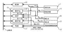
- the TPIM 19includes two motor control modules, MCP-A 22 and MCP-B 33 , and hybrid control module (‘HCP’) 5 , and is an element of the control system described hereinafter with regard to FIG. 2 .
- MCP-A 22transmits electrical energy to and from MG-A 56 by transfer conductors 29
- MCP-Bsimilarly transmits electrical energy to and from MG-B 72 by transfer conductors 31 .
- Electrical currentis transmitted to and from the ESD 74 in accordance with whether the ESD 74 is being charged or discharged.
- TPIM 19includes power inverters and respective motor control modules configured to receive motor control commands and control inverter states therefrom for providing motor drive or regeneration functionality.
- the inverterscomprise known complementary three-phase power electronics devices.
- MCP-A 22 and MCP-B 33each comprises controlled insulated gate bipolar transistors (IGBT) for converting DC power from the ESD 74 to AC power for powering one of the electrical machines MG-A 56 , MG-B 72 , by switching at high frequencies.
- IGBTinsulated gate bipolar transistors
- FIG. 2a schematic block diagram of the exemplary control system, comprising an architecture consisting of distributed control modules, is shown.
- the elements described hereinaftercomprise a subset of an overall vehicle control architecture, and are operable to provide coordinated system control of the powertrain system described herein.
- the control systemis operable to synthesize pertinent information and inputs, and execute algorithms to control various actuators to achieve control targets, including such parameters as fuel economy, emissions, performance, driveability, and protection of hardware, including batteries of ESD 74 and MG-A 56 and MG-B 72 .
- the distributed control module architectureincludes engine control module (‘ECM’) 23 , transmission control module (‘TCM’) 17 , battery pack control module (‘BPCM’) 21 , and TPIM 19 , which includes the HCP 5 and MCP-A 22 and MCP-B 33 in the embodiments described.
- UIUser Interface
- the distributed control module architectureincludes engine control module (‘ECM’) 23 , transmission control module (‘TCM’) 17 , battery pack control module (‘BPCM’) 21 , and TPIM 19 , which includes the HCP 5 and MCP-A 22 and MCP-B 33 in the embodiments described.
- UIUser Interface
- the devicesinclude an operator torque request (‘T O — REQ ’) and operator brake (‘BRAKE’), a transmission gear selector (i.e., PRNDL) (not shown), and, a vehicle speed cruise control (not shown).
- the transmission gear selectortypically has a discrete number of operator-selectable positions, including direction of the output, i
- the aforementioned control modulescommunicate with other control modules, sensors, and actuators via a local area network (‘LAN’) bus 6 , as described herein.
- Specific control modulesare configured to communicate via serial peripheral interface (‘SPI’) buses, as described herein.
- SPIserial peripheral interface
- the LAN bus 6facilitates structured communication between the various control modules consisting of sensor outputs, control parameters, and device commands.
- the communication protocol utilizedis application-specific.
- the LAN busprovides for robust messaging and interfacing between the aforementioned control modules, and other control modules providing functionality such as antilock brakes, traction control, and vehicle stability. Multiple communications buses may be used to improve communications speed and provide some level of signal redundancy and integrity.
- the HCP 5provides supervisory control of the hybrid powertrain system, serving to coordinate operation of the ECM 23 , TCM 17 , TPIM 19 , and BPCM 21 . Based upon various input signals from the UI 13 and the powertrain, including the ESD 74 , the HCP 5 generates various commands, including: the operator torque request (‘T O — REQ ’), a commanded output torque (‘T O — CMD ’) to driveline 90 , the engine input torque, T I , clutch torques (‘T CL — N ’) for the N various torque transfer clutches C 1 70 , C 2 62 , C 3 73 , C 4 75 of the transmission 10 ; and motor torque commands T A and T B for MG-A 56 and MG-B 72 .
- the TCM 17is operatively connected to the hydraulic control circuit 42 , including monitoring various pressure sensing devices (not shown) and generating and executing control signals for various solenoids to control pressure switches and control valves contained therein.
- the systemincludes direct electrical signal connection between various elements of the powertrain system and specific control devices to facilitate communication of information outside normal channels afforded by the LAN bus 6 , at a faster update rate to facilitate improved system control and diagnostic monitoring.
- the ECM 23is directly connected to the engine 14 via the plurality of discrete lines collectively shown as aggregate line 35 in FIG. 2 , some details of which are depicted in FIGS. 4 and 5 .
- Thisincludes a wire cable from the engine crankshaft position sensor 11 to provide engine speed, N E .
- the wire cable from the engine crank position sensor 11is directly wired in parallel to the one of the HCP control module of TPIM 19 , to provide direct signal information from crank position sensor 11 .
- the ECM 23is preferably further directly connected to the engine 14 via aggregate line 35 in order to communicate vehicle-related inputs including coolant temperature, coolant level, and a hood switch, among other.
- the TPIM 19preferably includes the HCP 5 , MCP-A 22 , and MCP-B 33 control modules. There is a first SPI bus 44 between HCP 5 and MCP-A 22 , and a second SPI bus 44 between MCP-A 22 and MCP-B 33 . Each SPI bus comprises a full-duplex synchronous serial data link permitting direct communication between the devices.
- the MCP-A 22directly and individually communicates with the HCP 5 and the MCP-B 33 via the first and second SPI buses 44 , thus achieving high-speed communications between the devices without communications delays.
- messagesare typically sent from the HCP 5 to the MCP-A 22 and MCP-B 33 over the LAN bus 6 each 6.25 millisecond loop.
- SCIserial control interface
- the typical SPI-bus 44comprises a 4-wire serial communications interface to provide a synchronous serial data link which supports a low/medium bandwidth (e.g., 1 megabaud) network connection among the control modules supporting the SPI.
- a synchronous clockshifts serial data into and out of microcontrollers of the control modules in blocks of 8 bits.
- the SPI busis a master/slave interface, with the master driving a serial clock, and data being simultaneously transmitted and received in a full-duplexed protocol.
- the mastercomprises the HCP 5 . Further specific details of SPI communications are known to a skilled practitioner and not discussed in detail herein.
- the ECM 23is operably connected to the engine 14 , and functions to acquire data from a variety of sensors and control a variety of actuators, respectively, of the engine 14 over a plurality of discrete lines collectively depicted as aggregate line 35 .
- the ECM 23receives the engine input torque command from the HCP 5 , and generates a desired axle torque, and an indication of actual engine input torque to the transmission, which is communicated to the HCP 5 .
- ECM 23is shown generally having bi-directional interface with engine 14 via aggregate line 35 .
- Various other parameters that may be sensed by ECM 23include engine coolant temperature and engine input speed, N E , to shaft 12 , which translate to transmission input speed, N I , manifold pressure, ambient air temperature, and ambient pressure.
- Various actuators that may be controlled by the ECM 23include fuel injectors, ignition modules, and throttle control modules.
- the TCM 17is operably connected to the transmission 10 and functions to acquire data from a variety of sensors and provide command signals to the transmission over a plurality of discrete lines collectively depicted as aggregate line 41 .
- Inputs from the TCM 17 to the HCP 5include estimated clutch torques for each of the N clutches, i.e., C 1 70 , C 2 62 , C 3 73 , C 4 75 , rotational output speed from transmission output sensor 84 , and signal outputs from hydraulic pressure switch devices PS 1 , PS 2 , PS 3 , PS 4 which are depicted with reference to FIG. 3 .
- Other actuators and sensorsmay be used to provide additional information from the TCM 17 to the HCP 5 for control purposes.
- the TCM 17monitors inputs from the pressure switches and selectively controls pressure control solenoids and shift solenoids to control various clutches to achieve various transmission operating modes, as described hereinbelow.
- the BPCM 21is signally connected one or more sensors operable to monitor electrical current or voltage parameters of the ESD 74 to provide information about the state of the batteries to the HCP 5 .
- Such informationincludes battery state-of-charge, amp-hour throughput, battery voltage and available battery power.
- Each of the aforementioned control modulesis preferably a general-purpose digital computer generally comprising a microprocessor or central processing unit, storage mediums comprising read only memory (‘ROM’), random access memory (‘RAM’), electrically programmable read only memory (‘EPROM’), high speed clock, analog to digital (‘A/D’) and digital to analog (‘D/A’) circuitry, and input/output circuitry and devices (‘I/O’) and appropriate signal conditioning and buffer circuitry.
- Each control modulehas a set of control algorithms, comprising resident program instructions and calibrations stored in ROM and executed to provide the respective functions of each computer. Information transfer between the various computers is preferably accomplished using the aforementioned LAN bus 6 .
- Algorithms for control and state estimation in each of the control modulesare typically executed during preset loop cycles such that each algorithm is executed at least once each loop cycle.
- Algorithms stored in the non-volatile memory devicesare executed by one of the central processing units and are operable to monitor inputs from the sensing devices and execute control and diagnostic routines to control operation of the respective device, using preset calibrations.
- Loop cyclesare typically executed at regular intervals, for example each 3.125, 6.25, 12.5, 25 and 100 milliseconds during ongoing engine and vehicle operation. Alternatively, algorithms may be executed in response to occurrence of an event.
- the exemplary two-mode, compound-split, electro-mechanical transmissionoperates in one of several operating range states comprising fixed gear operation and continuously variable operation, described with reference to Table 1, below.
- the various transmission operating range states described in the tableindicate which of the specific clutches C 1 70 , C 2 62 , C 3 73 , C 4 75 are applied for each of the operating range states.
- a first modei.e., Mode I
- the engine 14can be either on or off.
- a second modei.e., Mode II
- Engine Offis defined by engine input speed, N E , being equal to zero revolutions per minute (‘RPM), i.e., the engine crankshaft is not rotating.
- Modes I and IIrefer to circumstances in which the transmission functions are controlled by one applied clutch, i.e., either clutch C 1 62 or C 2 70 , and by the controlled speed and torque of the electric machines MG-A 56 and MG-B 72 , which can be referred to as a continuously variable transmission mode.
- This additional clutchmay be the unapplied one of clutch C 1 70 or clutch C 2 62 or clutch C 3 73 or C 4 75 , as depicted in Table 1, above.
- N I /N Ofixed ratio operation of input-to-output speed of the transmission.
- the rotations of machines MG-A 56 and MG-B 72i.e., N A and N B , are dependent on internal rotation of the mechanism as defined by the clutching and proportional to the input speed measured at shaft 12 .
- FIG. 3a schematic diagram providing a more detailed description of the exemplary electro-hydraulic system for controlling flow of hydraulic fluid in the exemplary transmission is shown.
- a main hydraulic pump 88driven off the input shaft 12 from the engine 14
- an auxiliary pump 110operatively electrically controlled by the TPIM 19 , provide pressurized fluid to the hydraulic control circuit 42 through valve 140 .
- the auxiliary pump 110preferably comprises an electrically-powered pump of an appropriate size and capacity to provide sufficient flow of pressurized hydraulic fluid into the hydraulic system when operational.
- Pressurized hydraulic fluidflows into hydraulic control circuit 42 , which is operable to selectively distribute hydraulic pressure to a series of devices, including the torque transfer clutches C 1 70 , C 2 62 , C 3 73 , and C 4 75 , active cooling circuits for MG-A 56 and MG-B 72 , and a base cooling circuit for cooling and lubricating the transmission 10 via passages 142 , 144 , including flow restrictors 148 , 146 (not depicted in detail).
- a series of devicesincluding the torque transfer clutches C 1 70 , C 2 62 , C 3 73 , and C 4 75 , active cooling circuits for MG-A 56 and MG-B 72 , and a base cooling circuit for cooling and lubricating the transmission 10 via passages 142 , 144 , including flow restrictors 148 , 146 (not depicted in detail).
- the TCM 17controls the various clutches to achieve various transmission operating modes through selective control of pressure control solenoids (‘PCS’) PCS 1 108 , PCS 2 112 , PCS 3 114 , PCS 4 116 and solenoid-controlled flow management valves X-valve 119 and Y-valve 121 .
- the circuitis fluidly connected to pressure switches PS 1 , PS 2 , PS 3 , and PS 4 via passages 124 , 122 , 126 , and 128 , respectively.
- the pressure control solenoid PCS 1 108has a control position of normally high and is operative to modulate magnitude of fluidic pressure in the hydraulic circuit through fluidic interaction with controllable pressure regulator 109 .
- Controllable pressure regulator 109interacts with PCS 1 108 to control hydraulic pressure in the hydraulic circuit 42 over a range of pressures, depending upon operating conditions as described hereinafter.
- Pressure control solenoid PCS 2 112has a control position of normally low, and is fluidly connected to spool valve 113 and operative to effect flow therethrough when actuated.
- Spool valve 113is fluidly connected to pressure switch PS 3 via passage 126 .
- Pressure control solenoid PCS 3 114has a control position of normally low, and is fluidly connected to spool valve 115 and operative to effect flow therethrough when actuated. Spool valve 115 is fluidly connected to pressure switch PS 1 via passage 124 .
- Pressure control solenoid PCS 4 116has a control position of normally low, and is fluidly connected to spool valve 117 and operative to effect flow therethrough when actuated. Spool valve 117 is fluidly connected to pressure switch PS 4 via passage 128 .
- the X-Valve 119 and Y-Valve 121each comprise flow management valves controlled by solenoids 118 , 120 , respectively, in the exemplary system, and have control states of High (‘1’) and Low (‘0’).
- the control statesrefer to positions of each valve with which to control flow to different devices in the hydraulic circuit 42 and the transmission 10 .
- the X-valve 119is operative to direct pressurized fluid to clutches C 3 73 and C 4 75 and cooling systems for stators of MG-A 56 and MG-B 72 via fluidic passages 136 , 138 , 144 , 142 respectively, depending upon the source of the fluidic input, as is described hereinafter.
- the Y-valve 121is operative to direct pressurized fluid to clutches C 1 70 and C 2 62 via fluidic passages 132 and 134 respectively, depending upon the source of the fluidic input, as is described hereinafter.
- the Y-valve 121is fluidly connected to pressure switch PS 2 via passage 122 .
- a more detailed description of the exemplary hydraulic control circuit 42is provided in commonly assigned U.S. patent application Ser. No. 11/263,216.
- Selective control of the X-valve 119 and Y-valve 121 and actuation of the solenoids PCS 2 , PCS 3 , and PCS 4facilitate flow of hydraulic fluid to selectively apply clutches C 1 70 , C 2 62 , C 3 73 , C 4 75 and provide cooling for the stators of MG-A 56 and MG-B 72 .
- the HCP 5 and one or more of the other control modulesdetermine the commanded output torque intended to meet the operator torque request to be effected at shaft 64 .
- Final vehicle accelerationis affected by other factors, including, e.g., road load, road grade, and vehicle mass.
- the operating modeis determined for the transmission based upon a variety of operating characteristics of the powertrain. This includes the operator torque request, typically communicated through the inputs to the UI 13 as previously described.
- the operating modemay be predicated on a powertrain torque demand caused by a control module command to operate of the electric machines in an electrical energy generating mode or in a torque generating mode.
- the operating modecan be determined by an optimization algorithm or routine operable to determine optimum system efficiency based upon operator demand for power, battery state of charge, and energy efficiencies of the engine 14 and MG-A 56 and MG-B 72 .
- the control systemmanages torque inputs from the engine 14 and MG-A 56 and MG-B 72 based upon an outcome of the executed optimization routine, and system optimization occurs to optimize system efficiencies to improve fuel economy and manage battery charging. Furthermore, operation can be determined based upon a fault in a component or system.
- the HCP 5monitors the parametric states of the torque-generative devices, and determines the output of the transmission required to arrive at the desired output torque, as described hereinbelow. Under the direction of the HCP 5 , the transmission 10 operates over a range of output speeds from slow to fast in order to meet the operator demand.
- the TCM 17 , ECM 23 , and TPIM 19are signally connected via LAN bus 6 , which provides structured communications therebetween. Furthermore, the TPIM 19 comprises control modules MCP-A 22 , HCP 5 , and MCP-B 33 , including internal SPI communications link 44 for direct communications therebetween, as previously described.
- the first subsystemcomprises the hydraulic circuit 42 of the transmission 10 which is directly connected to TCM 17 for signal transmission and clutch control thereof.
- TCM 17directly signally connected to each of the pressure switches PS 1 , PS 2 , PS 3 , PS 4 and output speed sensor 84 via discrete wiring harness cables.
- TCM 17is operatively connected to each of the pressure control solenoids and flow management valves of the hydraulic circuit.
- the TCM 17includes program code in the form of algorithms and predetermined calibrations to analyze the signals from the pressure monitoring devices and monitor the transmission output speed from sensor 84 . When one of the operating range states (described with reference to Table 1) is commanded, each of the clutches is applied or released, by actuating specific ones of the pressure control solenoids and flow management valves.
- Each of the pressure switcheshas an expected output, depending upon the commanded operating range state.
- the TCM 17 program codeperiodically monitors outputs of the pressure switches and compares it to the expected output to detect presence of a stuck clutch. When a stuck clutch is detected, the TCM 17 remediates, such remediation dependent upon which of the clutches is determined stuck, and whether it is stuck open (released) or closed (applied). Remediation preferably includes commanding the X-valve 119 to a ‘0’ or low operating state, to control the transmission in one of the continuously variable operating range states, as described with reference to Table 2, above. Other remediation may include limiting operation to a single gear or mode when it is determined that the X-valve 119 is stuck.
- the second subsystemcomprises the electric machines MG-A 56 and MG-B 72 which are directly connected to the TPIM 19 comprising the HCP 5 , MCP-A 22 and MCP-B 33 .
- the TPIM 19is directly signally connected to the resolver 80 of MG-A 56 via MCP-A 22 and directly signally connected to the resolver 82 of MG-B 72 via MCP-B 33 , each signal connection comprising discrete wiring harness cables.
- the signal, V SS-WHLfrom wheel speed sensors 94 of the driven wheels of the vehicle is input to the HCP 5 , from which the HCP 5 is able to determine and monitor the transmission output speed based upon an axle ratio.
- MCP-A 22 and MCP-B 33are operatively connected to the electric machines. Furthermore, the MCP-A 22 and MCP-B 33 each include program code in the form of algorithms and predetermined calibrations to analyze the signals from the resolvers and monitor the transmission output speed from the wheel speed sensors 94 .
- the TPIM 19monitors rotational speeds of MG-A 56 and MG-B 72 and the transmission output speed to determine which of the clutches is applied and which of the clutches is released, based upon whether or not there is zero slippage across each clutch. Slippage is determined based upon gear ratios and relative speeds of the clutches and electric machines.
- a comparisonis made between commanded clutch states for a commanded operating range state and the determined clutch states to identify whether and when one or more of the clutches is stuck closed (applied) or stuck open (released).
- a stuck-closed clutchis determined when one of the clutches has zero slippage when slippage is expected, thus indicating the clutch is applied.
- a stuck-open clutchis determined when one of the clutches has some level of slippage when zero slippage is expected, thus indicating the clutch is released.
- the TPIM 19also monitors electric current through each of MG-A 56 and MG-B 72 to compare commanded motor speeds to the transmission output speed. When a stuck clutch is identified, the HCP 5 remediates. The remediation comprises controlling mechanical power output of the electric machines, typically by reducing electric current flow to the electric machines to reduce mechanical torque output therefrom.
- the second subsystemincludes the transmission output speed sensor 84 directly signally connected to HCP 5 via a wire cable, from which the HCP is able to determine and monitor the transmission output speed.
- each of the embodiments describedthere are two independent subsystems to detect faults in clutch application, and two independent methods to remediate the operation of the transmission in the event of a detected fault in clutch application.
- the two subsystemsemploy separate and distinct sensors and control methods, thus having no shared failure modes, to reduce risk of unintended clutch states due to faults.
- the configurationpermits limited operation in presence of a single fault.
- the first subsystemmonitors hydraulic pressure and output from the pressure switches, and remediates using hydraulic controls, whereas the second subsystem monitors motor speeds and output speed and remediates using electric controls.
- the algorithmic codesare executed in different and separate control modules.
- a single control modulecan be adapted to monitor and control the hydraulic subsystem and the electric subsystem as described, albeit with some increased risk related to common-mode faults in the control module.
- the TCM 17is operatively connected to the flow management valves and pressure control solenoids to selectively control torque transfer clutch states, and is directly signally connected to the pressure monitoring devices to monitor the hydraulic circuit.
- the TCMexecutes algorithmic code to detect a fault in the torque transfer clutch states affecting the power flow to the output based upon the signal outputs of the pressure monitoring devices and executes remedial control upon detection of the fault.
- the HCP 5executes algorithmic code to detect any fault in the output of the transmission based upon the rotation of the electric machine, indicative of unexpected clutch states and, executes remedial control upon detection of a fault.
- the remedial control by the TCM 17comprises selectively controlling the flow management valves and pressure control solenoids to control transmission operation in the continuously variable operating range state, typically by controlling the X-valve to low state, as described with reference to Table 2.
- the remedial control by the HCP 5comprises controlling speed and torque output of the electric machines by controlling electric power thereto.
Landscapes
- Engineering & Computer Science (AREA)
- Mechanical Engineering (AREA)
- Chemical & Material Sciences (AREA)
- Combustion & Propulsion (AREA)
- Transportation (AREA)
- General Engineering & Computer Science (AREA)
- Health & Medical Sciences (AREA)
- Biomedical Technology (AREA)
- General Health & Medical Sciences (AREA)
- Automation & Control Theory (AREA)
- Control Of Transmission Device (AREA)
- Electric Propulsion And Braking For Vehicles (AREA)
Abstract
Description
| TABLE 1 | |
| Transmission Operating Range State | Applied Clutches |
| Mode I—Engine Off (MI_Eng_Off) | ||
| Mode I—Engine On (MI_Eng_On) | ||
| Fixed Gear Ratio 1 (FIG. 1) | ||
| Fixed Gear Ratio 2 (FIG. 2) | ||
| Mode II—Engine Off (MII_Eng_Off) | ||
| Mode II—Engine On (MII_Eng_On) | ||
| Fixed Gear Ratio 3 (FIG. 3) | ||
| Fixed Gear Ratio 4 (FIG. 4) | ||
| TABLE 2 | ||||||
| X- | Y- | |||||
| Valve | Valve | |||||
| Logic | Logic | PCS1 | PCS2 | PCS3 | PCS4 | |
| Operating | No | C2 | Normal | Normal | Normal | Normal |
| State | Latch | Latch | High | High | High | Low |
| Mode I | 0 | 0 | Line | MG-B | C1 | MG-A |
| (EVT | Modulation | Stator | Stator | |||
| Low) | Cool | Cool | ||||
| Mode II | 0 | 1 | Line | C2 | MG-B | MG-A |
| (EVT | Modulation | Stator | Stator | |||
| High) | Cool | Cool | ||||
| Low | 1 | 0 | Line | C2 | C1 | C4 |
| Range | Modulation | |||||
| FG1, FG2 | ||||||
| Mode I | ||||||
| High | 1 | 1 | Line | C2 | C3 | C4 |
| Range | Modulation | |||||
| FG3, FG4 | ||||||
| Mode II | ||||||
Claims (6)
Priority Applications (1)
| Application Number | Priority Date | Filing Date | Title |
|---|---|---|---|
| US12/956,219US8357074B2 (en) | 2007-09-26 | 2010-11-30 | Electro-mechanical transmission control system |
Applications Claiming Priority (2)
| Application Number | Priority Date | Filing Date | Title |
|---|---|---|---|
| US11/861,635US7867135B2 (en) | 2007-09-26 | 2007-09-26 | Electro-mechanical transmission control system |
| US12/956,219US8357074B2 (en) | 2007-09-26 | 2010-11-30 | Electro-mechanical transmission control system |
Related Parent Applications (1)
| Application Number | Title | Priority Date | Filing Date |
|---|---|---|---|
| US11/861,635DivisionUS7867135B2 (en) | 2007-09-26 | 2007-09-26 | Electro-mechanical transmission control system |
Publications (2)
| Publication Number | Publication Date |
|---|---|
| US20110070991A1 US20110070991A1 (en) | 2011-03-24 |
| US8357074B2true US8357074B2 (en) | 2013-01-22 |
Family
ID=40472283
Family Applications (2)
| Application Number | Title | Priority Date | Filing Date |
|---|---|---|---|
| US11/861,635Expired - Fee RelatedUS7867135B2 (en) | 2007-09-26 | 2007-09-26 | Electro-mechanical transmission control system |
| US12/956,219Expired - Fee RelatedUS8357074B2 (en) | 2007-09-26 | 2010-11-30 | Electro-mechanical transmission control system |
Family Applications Before (1)
| Application Number | Title | Priority Date | Filing Date |
|---|---|---|---|
| US11/861,635Expired - Fee RelatedUS7867135B2 (en) | 2007-09-26 | 2007-09-26 | Electro-mechanical transmission control system |
Country Status (3)
| Country | Link |
|---|---|
| US (2) | US7867135B2 (en) |
| CN (1) | CN101413580B (en) |
| DE (1) | DE102008048531A1 (en) |
Cited By (3)
| Publication number | Priority date | Publication date | Assignee | Title |
|---|---|---|---|---|
| US20130150209A1 (en)* | 2011-12-09 | 2013-06-13 | Hyundai Motor Company | Method for Diagnosing and Controlling an Unusual Hydraulic State of Hybrid Vehicle Transmission |
| US8652006B2 (en)* | 2012-05-01 | 2014-02-18 | GM Global Technology Operations LLC | Method and apparatus for operating a powertrain system upon detecting a stuck-closed clutch |
| US20140081491A1 (en)* | 2012-09-14 | 2014-03-20 | GM Global Technology Operations LLC | Acceleration profile-based control of an offgoing clutch operation |
Families Citing this family (27)
| Publication number | Priority date | Publication date | Assignee | Title |
|---|---|---|---|---|
| US7878932B2 (en)* | 2007-09-13 | 2011-02-01 | GM Global Technology Operations LLC | Method and apparatus to monitor a valve adapted to control mode to gear transitions during operation of an electro-mechanical transmission |
| US7867135B2 (en)* | 2007-09-26 | 2011-01-11 | GM Global Technology Operations LLC | Electro-mechanical transmission control system |
| DE102007050301B4 (en)* | 2007-10-22 | 2021-10-21 | Robert Bosch Gmbh | Method and device for detecting a malfunction of a clutch |
| US8092339B2 (en)* | 2007-11-04 | 2012-01-10 | GM Global Technology Operations LLC | Method and apparatus to prioritize input acceleration and clutch synchronization performance in neutral for a hybrid powertrain system |
| DE102008002691A1 (en)* | 2008-06-26 | 2009-12-31 | Robert Bosch Gmbh | Method and device for operating a vehicle with hybrid drive |
| KR20120029437A (en)* | 2009-06-05 | 2012-03-26 | 알리손 트랜스미션, 인크. | Electro-hydraulic control system calibration and diagnostics |
| US8646313B2 (en) | 2009-06-22 | 2014-02-11 | Ford Global Technologies, Llc | System and method to provide lubrication for a plug-in hybrid |
| US9855833B2 (en)* | 2009-06-22 | 2018-01-02 | Ford Global Technologies, Llc | System and method to provide lubrication for a plug-in hybrid |
| DE102011103461A1 (en)* | 2010-06-28 | 2011-12-29 | Schaeffler Technologies Gmbh & Co. Kg | Method for detecting the presence of a driver in a motor vehicle |
| US8534413B2 (en)* | 2011-10-14 | 2013-09-17 | Polaris Industries Inc. | Primary clutch electronic CVT |
| US8682550B2 (en) | 2011-10-14 | 2014-03-25 | Polaris Industries Inc. | Primary clutch electronic CVT |
| US9067598B2 (en)* | 2012-06-14 | 2015-06-30 | GM Global Technology Operations LLC | Method and apparatus for controlling a high-voltage electrical system for a multi-mode transmission |
| US9429232B2 (en)* | 2012-06-15 | 2016-08-30 | Allison Transmission, Inc. | Redundant controls for a multi-mode transmission |
| US8771137B2 (en)* | 2012-06-27 | 2014-07-08 | GM Global Technology Operations LLC | Method for use of hydraulically or electrically controlled solenoids under failed on conditions |
| US9352737B2 (en)* | 2012-10-08 | 2016-05-31 | Ford Global Technologies, Llc | Method and system for operating a hybrid powertrain |
| FR2997047B1 (en)* | 2012-10-18 | 2015-03-20 | Faar Industry | MOTORIZATION DEVICE FOR ELECTRIC VEHICLE |
| JP5803894B2 (en)* | 2012-12-25 | 2015-11-04 | トヨタ自動車株式会社 | vehicle |
| DE102013215906A1 (en)* | 2013-08-12 | 2015-02-12 | Zf Friedrichshafen Ag | Method and control device for operating an assembly of a vehicle |
| US10648554B2 (en) | 2014-09-02 | 2020-05-12 | Polaris Industries Inc. | Continuously variable transmission |
| US9797506B2 (en)* | 2014-09-15 | 2017-10-24 | GM Global Technology Operations LLC | Transmission node speed monitoring |
| JP6304173B2 (en)* | 2015-08-18 | 2018-04-04 | トヨタ自動車株式会社 | vehicle |
| KR101765618B1 (en)* | 2015-12-14 | 2017-08-07 | 현대자동차 주식회사 | Method for preventing engine clutch hazard of hybrid vehicle |
| CN106644460A (en)* | 2016-09-27 | 2017-05-10 | 北京新能源汽车股份有限公司 | Electric vehicle, gearbox detection system and gearbox detection method thereof |
| CN108591443B (en)* | 2018-01-05 | 2020-07-10 | 重庆青山工业有限责任公司 | Method for confirming and processing fault of vehicle gearbox |
| WO2019183051A1 (en) | 2018-03-19 | 2019-09-26 | Polaris Industries Inc. | Continuously variable transmission |
| EP3623242B1 (en)* | 2018-09-17 | 2022-09-07 | KNORR-BREMSE Systeme für Nutzfahrzeuge GmbH | A system and a method for controlling an electric vehicle |
| CN113237654B (en)* | 2021-05-28 | 2022-03-22 | 安徽江淮汽车集团股份有限公司 | Clutch detection method, vehicle and computer-readable storage medium |
Citations (211)
| Publication number | Priority date | Publication date | Assignee | Title |
|---|---|---|---|---|
| US5833570A (en)* | 1996-05-28 | 1998-11-10 | Toyota Jidosha Kabushiki Kaisha | Vehicle transmission shift control apparatus wherein torque of motor connected to automatic transmission is controlled to reduce shifting shock of transmission |
| US5842144A (en)* | 1995-06-07 | 1998-11-24 | Caterpillar Inc. | Default mode control system for a split torque transmission |
| US20040029677A1 (en)* | 2002-08-07 | 2004-02-12 | Honda Giken Kogyo Kabushiki Kaisha | Control system for stopping and starting vehicle engine |
| US6832148B1 (en) | 2003-10-14 | 2004-12-14 | General Motors Corporation | Automatic engine stop and restart mode for reducing emissions of a hybrid electric vehicle |
| US6868318B1 (en) | 2003-10-14 | 2005-03-15 | General Motors Corporation | Method for adjusting battery power limits in a hybrid electric vehicle to provide consistent launch characteristics |
| US20050080539A1 (en) | 2003-10-14 | 2005-04-14 | Hubbard Gregory A. | Method for determining preferred input operating points for a vehicle transmission |
| US20050080523A1 (en) | 2003-10-14 | 2005-04-14 | Bennett Adam C. | Silent operating mode for reducing emissions of a hybrid electric vehicle |
| US20050077867A1 (en) | 2003-10-14 | 2005-04-14 | Cawthorne William R. | Method of determining battery power limits for an energy storage system of a hybrid electric vehicle |
| US20050077877A1 (en) | 2003-10-14 | 2005-04-14 | Cawthorne William R. | Managing service life of a battery |
| US20050080535A1 (en) | 2003-10-14 | 2005-04-14 | Steinmetz Todd M. | Speed control for an electrically variable transmission |
| US20050080540A1 (en) | 2003-10-14 | 2005-04-14 | Steinmetz Todd M. | Synchronous shift control in an electrically variable transmission |
| US20050080538A1 (en) | 2003-10-14 | 2005-04-14 | Hubbard Gregory A. | Real-time operating parameter selection in a vehicular transmission |
| US20050080527A1 (en)* | 2003-10-14 | 2005-04-14 | Tao Xuefeng T. | Hybrid transmission member speed determination, sensor diagnostics and fault recovery |
| US20050076958A1 (en) | 2003-10-14 | 2005-04-14 | Foster Michael D. | Control apparatus, method and diagnostic for hydraulic fill and drain |
| US20050080537A1 (en) | 2003-10-14 | 2005-04-14 | Cawthorne William R. | Optimal selection of input torque considering battery utilization for a hybrid electric vehicle |
| US20050080541A1 (en) | 2003-10-14 | 2005-04-14 | Sah Jy-Jen F. | Two clutch fixed-ratio exit control for multi-mode hybrid drive |
| US20050182543A1 (en) | 2004-02-14 | 2005-08-18 | Sah Jy-Jen F. | Shift through neutral control in an electrically variable transmission |
| US20050182526A1 (en) | 2004-02-14 | 2005-08-18 | Hubbard Gregory A. | Optimal selection of input torque with stability of power flow for a hybrid electric vehicle |
| US20050182547A1 (en) | 2004-02-14 | 2005-08-18 | Sah Jy-Jen F. | Shift inhibit control for multi-mode hybrid drive |
| US20050182546A1 (en) | 2004-02-14 | 2005-08-18 | Tung-Ming Hsieh | Throttle phase out control |
| US20050189918A1 (en) | 2004-02-14 | 2005-09-01 | Weisgerber Scott T. | Energy storage system state of charge diagnostic |
| US6953409B2 (en) | 2003-12-19 | 2005-10-11 | General Motors Corporation | Two-mode, compound-split, hybrid electro-mechanical transmission having four fixed ratios |
| US20050252283A1 (en) | 2004-05-14 | 2005-11-17 | Heap Anthony H | Diagnostic method for a torque control of an electrically variable transmission |
| US20050252474A1 (en) | 2004-05-14 | 2005-11-17 | Sah Jy-Jen F | Multi-stage compression ignition engine start |
| US20050255967A1 (en) | 2004-05-14 | 2005-11-17 | Foster Michael D | Method of automatically flushing debris from an electrically-operated hydraulic valve |
| US20050255965A1 (en) | 2004-05-14 | 2005-11-17 | Tao Xuefeng T | Coordinated regenerative and engine retard braking for a hybrid vehicle |
| US20050255966A1 (en) | 2004-05-14 | 2005-11-17 | Tao Xuefeng T | Engine retard operation scheduling and management in a hybrid vehicle |
| US20050256617A1 (en) | 2004-05-14 | 2005-11-17 | Cawthorne William R | Method of undervoltage protection during engine cranking |
| US20050256623A1 (en) | 2004-05-15 | 2005-11-17 | Hubbard Gregory A | Method for dynamically determining peak output torque within battery constraints in a hybrid transmission including a parallel hybrid split |
| US20050255963A1 (en) | 2004-05-14 | 2005-11-17 | Tung-Ming Hsieh | Single motor recovery for an electrically variable transmission |
| US20050256626A1 (en) | 2004-05-14 | 2005-11-17 | Tung-Ming Hsieh | Method and apparatus to control hydraulic pressure in an electrically variable transmission |
| US20050255964A1 (en) | 2004-05-15 | 2005-11-17 | Heap Anthony H | Method of providing electric motor torque reserve in a hybrid electric vehicle |
| US20050252305A1 (en) | 2004-05-15 | 2005-11-17 | Hubbard Gregory A | Method for dynamically determining peak output torque in an electrically variable transmission |
| US20050256625A1 (en) | 2004-05-15 | 2005-11-17 | Sah Jy-Jen F | Hydraulic clutch state diagnostic and control |
| US20050256919A1 (en) | 2004-05-14 | 2005-11-17 | Cawthorne William R | Method of determining the derivative of an input signal |
| US20050256627A1 (en) | 2004-05-14 | 2005-11-17 | Sah Jy-Jen F | Acceleration limiting for a vehicle |
| US20050256629A1 (en) | 2004-05-14 | 2005-11-17 | Tao Xuefeng T | Method for automatic traction control in a hybrid electric vehicle |
| US20050256631A1 (en) | 2004-05-14 | 2005-11-17 | Cawthorne William R | Method of determining engine output power in a hybrid electric vehicle |
| US20050255968A1 (en) | 2004-05-14 | 2005-11-17 | Sah Jy-Jen F | Method for active engine stop of a hybrid electric vehicle |
| US20050256618A1 (en) | 2004-05-14 | 2005-11-17 | Tung-Ming Hsieh | Method of testing motor torque integrity in a hybrid electric vehicle |
| US20050256633A1 (en) | 2004-05-15 | 2005-11-17 | Heap Anthony H | Cost structure method including fuel economy and engine emission considerations |
| US7051859B2 (en)* | 2002-08-27 | 2006-05-30 | General Motors Corporation | Methods and apparatus for hill-holding transmission |
| US7154236B1 (en) | 2006-02-13 | 2006-12-26 | Gm Global Technology Operations, Inc. | Control system for hybrid powertrain |
| US20070149348A1 (en) | 2005-12-23 | 2007-06-28 | Holmes Alan G | Vehicle propulsion system |
| US20070191181A1 (en) | 2006-02-13 | 2007-08-16 | Burns Robert D | Method and apparatus for controlling vehicle rollback |
| US20070225889A1 (en) | 2006-03-22 | 2007-09-27 | Morris Robert L | Jerk management using multivariable active driveline damping |
| US20070225886A1 (en) | 2006-03-22 | 2007-09-27 | Morris Robert L | Parameter state estimation |
| US20070225888A1 (en) | 2006-03-22 | 2007-09-27 | Morris Robert L | Driveline lash estimation and clunk management using multivariable active driveline damping |
| US20070225887A1 (en) | 2006-03-22 | 2007-09-27 | Morris Robert L | Method and apparatus for multivariate active driveline damping |
| US20070260381A1 (en) | 2006-05-03 | 2007-11-08 | Sah Jy-Jen F | Synchronous shift execution for hybrid transmission |
| US20070276569A1 (en) | 2006-05-25 | 2007-11-29 | Sah Jy-Jen F | Method and apparatus to control an electro-mechanical transmission during shifting event |
| US20070284162A1 (en) | 2006-06-07 | 2007-12-13 | Zettel Andrew M | Method for operating a hybrid electric powertrain based on predictive effects upon an electrical energy storage device |
| US20070285063A1 (en) | 2006-06-07 | 2007-12-13 | Zettel Andrew M | Method and apparatus for quantifying quiescent period temperature effects upon an electric energy storage device |
| US20070284176A1 (en) | 2006-05-25 | 2007-12-13 | Sah Jy-Jen F | Method and apparatus to control hydraulic pressure in an electro-mechanical transmission |
| US20070285059A1 (en) | 2006-06-07 | 2007-12-13 | Zettel Andrew M | Method and apparatus for real-time life estimation of an electric energy storage device |
| US20070285061A1 (en) | 2006-06-07 | 2007-12-13 | Zettel Andrew M | Method and apparatus for real-time life estimation of an electric energy storage device in a hybrid electric vehicle |
| US20070285060A1 (en) | 2006-06-07 | 2007-12-13 | Zettel Andrew M | Method and apparatus for determining the effect of temperature upon life expectancy of an electric energy storage device in a hybrid electric vehicle |
| US20070284163A1 (en) | 2006-06-07 | 2007-12-13 | Heap Anthony H | Method and apparatus for control of a hybrid electric vehicle to achieve a target life objective for an energy storage device |
| US20070285097A1 (en) | 2006-06-07 | 2007-12-13 | Zettel Andrew M | Method and apparatus for predicting change in an operating state of an electric energy storage device |
| US20080004779A1 (en) | 2006-06-30 | 2008-01-03 | Sah Jy-Jen F | Apparatus and method to control transmission torque output during a gear-to-gear shift |
| US20080028879A1 (en) | 2006-08-04 | 2008-02-07 | Robinette Richard E | Method and apparatus for fault-tolerant transmission gear selector lever position determination |
| US20080032855A1 (en) | 2006-08-04 | 2008-02-07 | Sah Jy-Jen F | Method and apparatus to control an electro-hydraulic transmission during shifting event |
| US20080064559A1 (en) | 2006-09-11 | 2008-03-13 | Cawthorne William R | Control system architecture for a hybrid powertrain |
| US20080064562A1 (en) | 2006-09-13 | 2008-03-13 | Aettel Andrew M | Method and apparatus to monitor operation of an auxiliary hydraulic pump in a transmission |
| US20080103003A1 (en) | 2006-10-26 | 2008-05-01 | Sah Jy-Jen F | Method and apparatus to control operation of a hydraulic control circuit for an electro-mechanical transmission |
| US20080120002A1 (en) | 2006-11-17 | 2008-05-22 | Heap Anthony H | Control architecture and method for two-dimensional optimization of input speed and input torque in mode for a hybrid powertrain system |
| US20080120001A1 (en) | 2006-11-17 | 2008-05-22 | Heap Anthony H | Control architecture for selection of optimal mode or gear and input speed for a hybrid powertrain system |
| US20080120000A1 (en) | 2006-11-17 | 2008-05-22 | Heap Anthony H | Control architecture for optimization and control of a hybrid powertrain system |
| US20080119320A1 (en) | 2006-11-17 | 2008-05-22 | Wu Peter E | Method and apparatus for controlling an electro-mechanical transmission during a shift execution |
| US20080119321A1 (en) | 2006-11-17 | 2008-05-22 | Heap Anthony H | Control architecture and method for two-dimensional optimization of input torque and motor torque in fixed gear for a hybrid powertrain system |
| US20080176709A1 (en) | 2007-01-24 | 2008-07-24 | Wu Peter E | Method and apparatus to monitor devices of a hydraulic circuit of an electro-mechanical transmission |
| US20080176706A1 (en) | 2007-01-24 | 2008-07-24 | Wu Peter E | Method and apparatus to control operation of an electro-mechanical transmission |
| US20080183372A1 (en) | 2007-01-31 | 2008-07-31 | Snyder Bryan R | Method and apparatus to determine pressure in an unfired cylinder |
| US20080182696A1 (en)* | 2006-08-04 | 2008-07-31 | Sah Jy-Jen F | Method and apparatus to control operation of a hydraulic control circuit for an electro-mechanical transmission |
| US20080181280A1 (en) | 2007-01-31 | 2008-07-31 | Wang Wei D | Method and apparatus to monitor a temperature sensing device |
| US20080234097A1 (en) | 2007-03-20 | 2008-09-25 | Sah Jy-Jen F | Clutch control for hybrid transmission |
| US20080236921A1 (en) | 2007-03-29 | 2008-10-02 | Huseman Steven C | Method for controlling engine speed in a hybrid electric vehicle |
| US20080243346A1 (en) | 2007-03-29 | 2008-10-02 | Huseman Steven C | Method and apparatus for controlling power flow in a hybrid powertrain system |
| US20080249745A1 (en) | 2006-06-07 | 2008-10-09 | Heap Anthony H | Method and apparatus for management of an electric energy storage device to achieve a target life objective |
| US20080262698A1 (en) | 2007-04-19 | 2008-10-23 | Lahti John L | Method and apparatus to determine instantaneous engine power loss for a powertrain system |
| US20080262694A1 (en) | 2007-04-19 | 2008-10-23 | Heap Anthony H | Method and apparatus to optimize engine warm up |
| US20080272717A1 (en)* | 2007-05-03 | 2008-11-06 | Gleason Sean E | Method and apparatus to determine rotational position of an electrical machine |
| US20080275611A1 (en) | 2007-05-03 | 2008-11-06 | Snyder Bryan R | Method and apparatus to determine rotational position of an internal combustion engine |
| US20080275624A1 (en) | 2007-05-03 | 2008-11-06 | Snyder Bryan R | Method and apparatus to control engine restart for a hybrid powertrain system |
| US20080275625A1 (en) | 2007-05-03 | 2008-11-06 | Snyder Bryan R | Method and apparatus to control engine stop for a hybrid powertrain system |
| US20080287255A1 (en) | 2007-05-14 | 2008-11-20 | Snyder Bryan R | Control architecture and method to evaluate engine off operation of a hybrid powertrain system operating in a continuously variable mode |
| US20090069989A1 (en) | 2007-09-11 | 2009-03-12 | Heap Anthony H | Method and control architecture for selection of optimal engine input torque for a powertrain system |
| US20090069148A1 (en) | 2007-09-11 | 2009-03-12 | Heap Anthony H | Control architecture and method for one-dimensional optimization of input torque and motor torque in fixed gear for a hybrid powertrain system |
| US20090070019A1 (en) | 2007-09-11 | 2009-03-12 | Heap Anthony H | Method and control architecture for optimization of engine fuel-cutoff selection and engine input torque for a hybrid powertrain system |
| US20090076679A1 (en)* | 2007-09-13 | 2009-03-19 | Martini Ryan D | Method and apparatus to monitor an output speed sensor during operation of an electro-mechanical transmission |
| US20090082150A1 (en) | 2007-09-26 | 2009-03-26 | Gm Global Technology Operations, Inc. | Electro-mechanical transmission control system |
| US20090082170A1 (en) | 2007-09-26 | 2009-03-26 | Gm Global Technology Operations, Inc. | Method and control architecture for optimization of cylinder deactivation selection and engine input torque for a hybrid powertrain system |
| US20090088294A1 (en) | 2007-09-28 | 2009-04-02 | Gm Global Technology Operations, Inc. | Thermal protection of an electric drive system |
| US20090105896A1 (en) | 2007-10-23 | 2009-04-23 | Gm Global Technology Operations, Inc. | Method for controlling power flow within a powertrain system |
| US20090105914A1 (en) | 2007-10-19 | 2009-04-23 | Gm Global Technology Operations, Inc. | Method and system for inhibiting operation in a commanded operating range state for a transmission of a powertrain system |
| US20090105039A1 (en) | 2007-10-23 | 2009-04-23 | Gm Global Technlogy Operations, Inc. | Method for model based clutch control and torque estimation |
| US20090105898A1 (en) | 2007-10-23 | 2009-04-23 | Gm Global Technology Operations, Inc. | Method for monitoring a motor speed sensor |
| US20090112420A1 (en) | 2007-10-29 | 2009-04-30 | Gm Global Technology Operations, Inc. | Method and apparatus for monitoring a transmission range selector in a hybrid powertrain transmission |
| US20090111637A1 (en) | 2007-10-26 | 2009-04-30 | Gm Global Technology Operations, Inc. | Method and apparatus to control hydraulic pressure for component lubrication in an electro-mechanical transmission |
| US20090112418A1 (en) | 2007-10-27 | 2009-04-30 | Gm Global Technology Operations, Inc. | Method and apparatus for securing an operating range state mechanical transmission |
| US20090112416A1 (en) | 2007-10-29 | 2009-04-30 | Gm Global Technology Operations, Inc. | Method and apparatus to control input speed profile during inertia speed phase for a hybrid powertrain system |
| US20090112422A1 (en) | 2007-10-26 | 2009-04-30 | Gm Global Technology Operations, Inc. | Method and apparatus to control logic valves for hydraulic flow control in an electro-mechanical transmission |
| US20090112385A1 (en) | 2007-10-29 | 2009-04-30 | Gm Global Technology Operations, Inc. | Method for determining a power constraint for controlling a powertrain system |
| US20090112421A1 (en) | 2007-10-26 | 2009-04-30 | Gm Global Technology Operations, Inc. | Method and apparatus to control hydraulic line pressure in an electro-mechanical transmission |
| US20090111643A1 (en) | 2007-10-26 | 2009-04-30 | Gm Global Technology Operations, Inc. | Method and apparatus to control clutch fill pressure in an electro-mechanical transmission |
| US20090112427A1 (en) | 2007-10-25 | 2009-04-30 | Gm Global Technology Operations, Inc. | Method and apparatus for remediation of and recovery from a clutch slip event in a hybrid powertrain system |
| US20090112495A1 (en) | 2007-10-26 | 2009-04-30 | Gm Global Technology Operations, Inc. | Method for estimating battery life in a hybrid powertrain |
| US20090108673A1 (en) | 2007-10-25 | 2009-04-30 | Gm Globaltechnology Operations, Inc. | Method for determining a voltage level across an electric circuit of a powertrain |
| US20090112412A1 (en) | 2007-10-31 | 2009-04-30 | Gm Global Technology Operations, Inc. | Method and apparatus to monitor output of an electro-mechanical transmission |
| US20090111642A1 (en) | 2007-10-27 | 2009-04-30 | Gm Global Technology Operations, Inc. | Method and apparatus to control clutch stroke volume in an electro-mechanical transmission |
| US20090111645A1 (en) | 2007-10-29 | 2009-04-30 | Gm Global Technology Operations, Inc. | Method and apparatus to create a pseudo torque phase during oncoming clutch engagement to prevent clutch slip for a hybrid powertrain system |
| US20090111640A1 (en) | 2007-10-29 | 2009-04-30 | Gm Global Technology Operations, Inc. | Method and apparatus for monitoring regenerative operation in a hybrid powertrain system |
| US20090112419A1 (en) | 2007-10-25 | 2009-04-30 | Gm Global Technology Operations, Inc. | Method and apparatus to control off-going clutch torque during torque phase for a hybrid powertrain system |
| US20090112423A1 (en) | 2007-10-29 | 2009-04-30 | Gm Global Technology Operations, Inc. | Method and apparatus to control operation of a hydraulic pump for an electro-mechanical transmission |
| US20090112392A1 (en) | 2007-10-27 | 2009-04-30 | Gm Global Technology Operations, Inc. | Method and apparatus for monitoring processor integrity in a distributed control module system for a powertrain system |
| US20090107745A1 (en) | 2007-10-25 | 2009-04-30 | Gm Global Technology Operations, Inc. | Method and system for monitoring signal integrity in a distributed controls system |
| US20090112399A1 (en) | 2007-10-27 | 2009-04-30 | Gm Global Technology Operations, Inc. | Method and apparatus for monitoring software and signal integrity in a distributed control module system for a powertrain system |
| US20090111644A1 (en) | 2007-10-25 | 2009-04-30 | Gm Global Technology Operations, Inc. | Method and apparatus for clutch torque control in mode and fixed gear for a hybrid powertrain system |
| US20090112429A1 (en) | 2007-10-26 | 2009-04-30 | Gm Global Technology Operations, Inc. | Method and apparatus to control clutch pressures in an electro-mechanical transmission |
| US20090112428A1 (en) | 2007-10-26 | 2009-04-30 | Gm Global Technology Operations, Inc. | Method and apparatus to determine clutch slippage in an electro-mechanical transmission |
| US20090107755A1 (en) | 2007-10-26 | 2009-04-30 | Gm Global Technology Operations, Inc. | Method and apparatus to control motor cooling in an electro-mechanical transmission |
| US20090112417A1 (en) | 2007-10-29 | 2009-04-30 | Gm Global Technology Operations, Inc. | Method and apparatus to produce a smooth input speed profile in mode for a hybrid powertrain system |
| US20090118942A1 (en) | 2007-11-03 | 2009-05-07 | Gm Global Technology Operations, Inc. | Method for determining constraints on input torque in a hybrid transmission |
| US20090118914A1 (en) | 2007-11-05 | 2009-05-07 | Gm Global Technology Operations, Inc. | Method for operating an internal combustion engine for a hybrid powertrain system |
| US20090118091A1 (en) | 2007-11-07 | 2009-05-07 | Gm Global Technology Operations, Inc. | Method and apparatus to control temperature of an exhaust aftertreatment system for a hybrid powertrain |
| US20090115377A1 (en) | 2007-11-04 | 2009-05-07 | Gm Global Technology Operations, Inc. | Method of externally charging a powertrain |
| US20090118080A1 (en) | 2007-11-04 | 2009-05-07 | Gm Global Technology Operations, Inc. | Method for managing electric power within a powertrain system |
| US20090118941A1 (en) | 2007-11-05 | 2009-05-07 | Gm Global Technology Operations, Inc. | Method and apparatus for dynamic output torque limiting for a hybrid powertrain system |
| US20090118952A1 (en) | 2007-11-03 | 2009-05-07 | Gm Global Technology Operations, Inc. | Control architecture and method for two-dimensional optimization of input speed and input power including search windowing |
| US20090115352A1 (en) | 2007-11-04 | 2009-05-07 | Gm Global Technology Operations, Inc. | Method and apparatus for constraining output torque in a hybrid powertrain system |
| US20090118917A1 (en) | 2007-11-07 | 2009-05-07 | Gm Global Technology Operations, Inc. | Method and apparatus to control launch of a vehicle having an electro-mechanical transmission |
| US20090118880A1 (en) | 2007-11-07 | 2009-05-07 | Gm Global Technology Operations, Inc. | Method for predicting a speed output of a hybrid powertrain system |
| US20090118932A1 (en) | 2007-11-04 | 2009-05-07 | Gm Global Technology Operations, Inc. | Engine control system for torque management in a hybrid powertrain system |
| US20090118940A1 (en) | 2007-11-05 | 2009-05-07 | Gm Global Technology Operations, Inc. | Method for operating a powertrain system to control engine stabilization |
| US20090118079A1 (en) | 2007-11-02 | 2009-05-07 | Gm Global Technology Operations, Inc. | Method for controlling voltage within a powertrain system |
| US20090118933A1 (en) | 2007-11-05 | 2009-05-07 | Gm Global Technology Operations, Inc. | Method to compensate for transmission spin loss for a hybrid powertrain system |
| US20090118951A1 (en) | 2007-11-04 | 2009-05-07 | Gm Global Technology Operations, Inc. | Method for developing a trip cost structure to understand input speed trip for a hybrid powertrain system |
| US20090118886A1 (en) | 2007-11-03 | 2009-05-07 | Gm Global Technology Operations, Inc. | Method of operating a vehicle utilizing regenerative braking |
| US20090118094A1 (en) | 2007-11-03 | 2009-05-07 | Gm Global Technology Operations, Inc. | Method for determining input speed acceleration limits in a hybrid transmission |
| US20090118935A1 (en) | 2007-11-05 | 2009-05-07 | Gm Global Technology Operations, Inc. | Method for controlling a hybrid powertrain system based upon hydraulic pressure and clutch reactive torque capacity |
| US20090118929A1 (en) | 2007-11-02 | 2009-05-07 | Gm Global Technology Operations, Inc | Predicted and immediate output torque control architecture for a hybrid powertrain system |
| US20090118888A1 (en) | 2007-11-03 | 2009-05-07 | Gm Global Technology Operations, Inc. | Method for controlling regenerative braking in a vehicle |
| US20090118924A1 (en) | 2007-11-01 | 2009-05-07 | Gm Global Technology Operations, Inc. | System constraints method of determining minimum and maximum torque limits for an electro-mechanical powertrain system |
| US20090118950A1 (en) | 2007-11-05 | 2009-05-07 | Gm Global Technology Operations, Inc. | Method and apparatus to determine a preferred output torque for operating a hybrid transmission in a continuously variable mode |
| US20090118884A1 (en) | 2007-11-04 | 2009-05-07 | Gm Global Technology Operations, Inc. | Method for controlling a powertrain system based upon torque machine temperature |
| US20090118085A1 (en) | 2007-11-05 | 2009-05-07 | Gm Global Technology Operations, Inc. | Method and apparatus for adapting engine operation in a hybrid powertrain system |
| US20090115350A1 (en) | 2007-11-01 | 2009-05-07 | Gm Global Technology Operations, Inc. | Method for determining an achievable torque operating region for a transmission |
| US20090118879A1 (en) | 2007-11-05 | 2009-05-07 | Gm Global Technology Operations, Inc. | Method for predicting an operator torque request of a hybrid powertrain system |
| US20090118883A1 (en) | 2007-11-03 | 2009-05-07 | Gm Global Technology Operations, Inc. | Method for operating an engine in a hybrid powertrain system |
| US20090118936A1 (en) | 2007-11-04 | 2009-05-07 | Gm Global Technology Operations, Inc. | Control of engine torque during upshift and downshift torque phase for a hybrid powertrain system |
| US20090115351A1 (en) | 2007-11-02 | 2009-05-07 | Gm Global Technology Operations, Inc. | Method for managing electric power in a powertrain system |
| US20090118076A1 (en) | 2007-11-05 | 2009-05-07 | Gm Global Technology Operations, Inc. | Method for preferential selection of mode and gear and input speed based on multiple engine state fueling costs for a hybrid powertrain system |
| US20090118885A1 (en) | 2007-11-04 | 2009-05-07 | Gm Global Technology Operations, Inc. | System architecture for a blended braking system in a hybrid powertrain system |
| US20090118962A1 (en) | 2007-11-04 | 2009-05-07 | Gm Global Technology Operations, Inc. | Method for controlling output power of an energy storage device in a powertrain system |
| US20090118949A1 (en) | 2007-11-02 | 2009-05-07 | Gm Global Technology Operations, Inc. | Method and apparatus for developing a deceleration-based synchronous shift schedule |
| US20090118084A1 (en) | 2007-11-04 | 2009-05-07 | Gm Global Technology Operatons, Inc. | Method and apparatus to perform asynchronous shifts with oncoming slipping clutch torque for a hybrid powertrain system |
| US20090118969A1 (en) | 2007-11-07 | 2009-05-07 | Gm Global Technology Operations, Inc. | Method and apparatus to control warm-up of an exhaust aftertreatment system for a hybrid powertrain |
| US20090118877A1 (en) | 2007-11-03 | 2009-05-07 | Gm Global Technology Operations, Inc. | Creation and depletion of short term power capability in a hybrid electric vehicle |
| US20090118078A1 (en) | 2007-11-07 | 2009-05-07 | Gm Global Technology Operations, Inc. | Method and apparatus for controlling a hybrid powertrain system |
| US20090118943A1 (en) | 2007-11-05 | 2009-05-07 | Gm Global Technology Operations, Inc. | Method and apparatus to determine a preferred output torque in mode and fixed gear operation with clutch torque constraints for a hybrid powertrain system |
| US20090118918A1 (en) | 2007-11-03 | 2009-05-07 | Gm Global Technology Operations, Inc. | Method for stabilization of optimal input speed in mode for a hybrid powertrain system |
| US20090118919A1 (en) | 2007-11-04 | 2009-05-07 | Gm Global Technology Operations, Inc. | Method for determining inertia effects for a hybrid powertrain system |
| US20090115349A1 (en) | 2007-11-07 | 2009-05-07 | Gm Global Technology Operations, Inc. | Method and control architecture to determine motor torque split in fixed gear operation for a hybrid powertrain system |
| US20090118957A1 (en) | 2007-11-04 | 2009-05-07 | Gm Global Technology Operations, Inc. | Optimal selection of blended braking capacity for a hybrid electric vehicle |
| US20090118945A1 (en) | 2007-11-04 | 2009-05-07 | Gm Global Technology Operations, Inc. | Method for managing lash in a driveline |
| US20090118948A1 (en) | 2007-11-04 | 2009-05-07 | Gm Global Technology Operations, Inc. | Method and apparatus for maximum and minimum output torque performance by selection of hybrid range state and input speed for a hybrid powertrain system |
| US20090118923A1 (en) | 2007-11-04 | 2009-05-07 | Gm Global Technology Operations, Inc. | Method for controlling a powertrain system based on penalty costs |
| US20090118928A1 (en) | 2007-11-04 | 2009-05-07 | Gm Global Technology Operations, Inc. | Control of engine torque for traction and stability control events for a hybrid powertrain system |
| US20090118083A1 (en) | 2007-11-04 | 2009-05-07 | Gm Global Technology Operations, Inc. | Method and apparatus to control engine torque to peak main pressure for a hybrid powertrain system |
| US20090118920A1 (en) | 2007-11-03 | 2009-05-07 | Gm Global Technology Operations, Inc. | Optimal selection of hybrid range state and/or input speed with a blended braking system in a hybrid electric vehicle |
| US20090118963A1 (en) | 2007-11-02 | 2009-05-07 | Gm Global Technology Operations, Inc. | Method for altitude-compensated transmission shift scheduling |
| US20090118938A1 (en) | 2007-11-04 | 2009-05-07 | Gm Global Technology Operations, Inc. | Method for controlling a powertrain system based upon energy storage device temperature |
| US20090118947A1 (en) | 2007-11-04 | 2009-05-07 | Gm Global Technology Operations, Inc. | Method for selection of optimal mode and gear and input speed for preselect or tap up/down operation |
| US20090118937A1 (en) | 2007-11-02 | 2009-05-07 | Gm Global Technology Operations, Inc. | Method for operating a powertrain system to transition between engine states |
| US20090115408A1 (en) | 2007-11-06 | 2009-05-07 | Gm Global Technology Operations, Inc. | Method and apparatus to monitor position of a rotatable shaft |
| US20090115365A1 (en) | 2007-11-01 | 2009-05-07 | Gm Global Technology Operations, Inc. | Method of determining torque limit with motor torque and battery power constraints |
| US20090118954A1 (en) | 2007-11-03 | 2009-05-07 | Gm Global Technology Operations, Inc. | Method for monitoring an auxiliary pump for a hybrid powertrain |
| US20090118882A1 (en) | 2007-11-04 | 2009-05-07 | Gm Global Technology Operations, Inc. | Control architecture for output torque shaping and motor torque determination for a hybrid powertrain system |
| US20090118093A1 (en) | 2007-11-02 | 2009-05-07 | Gm Global Technology Oprations, Inc. | Control system for engine torque management for a hybrid powertrain system |
| US20090115373A1 (en) | 2007-11-04 | 2009-05-07 | Gm Global Technology Operations, Inc. | Method of charging a powertrain |
| US20090118930A1 (en) | 2007-11-05 | 2009-05-07 | Gm Global Technology Operations, Inc. | Method and apparatus for developing a control architecture for coordinating shift execution and engine torque control |
| US20090118081A1 (en) | 2007-11-04 | 2009-05-07 | Gm Global Technology Operations, Inc. | Method for controlling power actuators in a hybrid powertrain system |
| US20090118939A1 (en) | 2007-11-04 | 2009-05-07 | Gm Global Technology Operations, Inc. | Method for controlling an engine of a hybrid powertrain in a fuel enrichment mode |
| US20090115353A1 (en) | 2007-11-05 | 2009-05-07 | Gm Global Technology Operations, Inc. | Method of determining output torque limits of a hybrid transmission operating in a fixed gear operating range state |
| US20090118087A1 (en) | 2007-11-01 | 2009-05-07 | Gm Global Technology Operations, Inc. | System constraints method ofcontrolling operation of an electro-mechanical transmission with an additional constraint range |
| US20090118089A1 (en) | 2007-11-04 | 2009-05-07 | Gm Global Technology Operations, Inc. | Method for load-based stabilization of mode and fixed gear operation of a hybrid powertrain system |
| US20090118971A1 (en) | 2007-11-05 | 2009-05-07 | Gm Global Technology Operations, Inc. | Method and apparatus for determination of fast actuating engine torque for a hybrid powertrain system |
| US20090118927A1 (en) | 2007-11-07 | 2009-05-07 | Gm Global Technology Operations, Inc. | Method for controlling a speed level and torque of an engine within a powertrain |
| US20090118090A1 (en) | 2007-11-07 | 2009-05-07 | Gm Global Technology Operations, Inc. | Method and apparatus to control engine temperature for a hybrid powertrain |
| US20090118086A1 (en) | 2007-11-04 | 2009-05-07 | Gm Global Technology Operations, Inc. | Method and apparatus to offload offgoing clutch torque with asynchronous oncoming clutch torque, engine and motor torque for a hybrid powertrain system |
| US20090118946A1 (en) | 2007-11-04 | 2009-05-07 | Gm Global Technology Operations, Inc. | Method and apparatus to provide necessary output torque reserve by selection of hybrid range state and input speed for a hybrid powertrain system |
| US20090118901A1 (en) | 2007-11-05 | 2009-05-07 | Gm Global Technology Operations, Inc. | Method and apparatus for securing output torque in a distributed control module system for a powertrain system |
| US20090118915A1 (en) | 2007-11-04 | 2009-05-07 | Gm Global Technology Operations, Inc. | Method and apparatus to prioritize transmission output torque and input acceleration for a hybrid powertrain system |
| US20090118934A1 (en) | 2007-11-04 | 2009-05-07 | Gm Global Technology Operatons, Inc. | Method for determining a preferred engine operation in a hybrid powertrain system during blended braking |
| US20090118075A1 (en) | 2007-11-04 | 2009-05-07 | Gm Global Technology Operations, Inc. | Method for preferential selection of modes and gear with inertia effects for a hybrid powertrain system |
| US20090118925A1 (en) | 2007-11-02 | 2009-05-07 | Gm Global Technology Operations, Inc. | System constraints method of controlling operation of an electro-mechanical transmission with two external input torque ranges |
| US20090115491A1 (en) | 2007-11-01 | 2009-05-07 | Gm Global Technology Operations, Inc. | Prediction strategy for thermal management and protection of power electronic hardware |
| US20090118926A1 (en) | 2007-11-02 | 2009-05-07 | Gm Global Technology Operations, Inc. | Method for controlling input torque provided to a transmission |
| US20090118921A1 (en) | 2007-11-03 | 2009-05-07 | Gm Global Technology Operations, Inc. | Method for stabilization of mode and fixed gear for a hybrid powertrain system |
| US20090118999A1 (en) | 2007-11-04 | 2009-05-07 | Gm Global Technology Operations, Inc. | Method for operating an internal combustion engine to transmit power to a driveline |
| US20090118887A1 (en) | 2007-11-03 | 2009-05-07 | Gm Global Technology Operations, Inc. | Method for controlling regenerative braking and friction braking |
| US20090118944A1 (en) | 2007-11-05 | 2009-05-07 | Gm Global Technology Operations, Inc. | Method and apparatus to determine a preferred output torque for operating a hybrid transmission in a fixed gear operating range state |
| US20090118922A1 (en) | 2007-11-04 | 2009-05-07 | Gm Global Technology Operations, Inc. | Method and apparatus for soft costing input speed and output speed in mode and fixed gear as function of system temperatures for cold and hot operation for a hybrid powertrain system |
| US20090118931A1 (en) | 2007-11-02 | 2009-05-07 | Gm Global Technology Operations, Inc. | Method and apparatus to reprofile input speed during speed phase during constrained conditions for a hybrid powertrain system |
| US20090118916A1 (en) | 2007-11-04 | 2009-05-07 | Gm Global Technology Operations, Inc. | Method to manage a high voltage system in a hybrid powertrain system |
| US20090118074A1 (en) | 2007-11-06 | 2009-05-07 | Gm Global Technology Operations, Inc. | Method and apparatus to monitor rotational speeds in an electro-mechanical transmission |
| US20090118077A1 (en) | 2007-11-02 | 2009-05-07 | Gm Global Technology Operations, Inc. | System constraints method of controlling operation of an electro-mechanical transmission with an additional constraint |
| US20090118082A1 (en) | 2007-11-04 | 2009-05-07 | Gm Global Technology Operations, Inc. | Method and apparatus to prioritize input acceleration and clutch synchronization performance in neutral for a hybrid powertrain system |
| US20090118964A1 (en) | 2007-11-05 | 2009-05-07 | Gm Global Technology Operations, Inc. | Method for controlling electric boost in a hybrid powertrain |
| US20090115354A1 (en) | 2007-11-04 | 2009-05-07 | Gm Global Technology Operations, Inc. | Method for electric power boosting in a powertrain system |
| US20090144002A1 (en) | 2007-11-07 | 2009-06-04 | Gm Global Technology Operations, Inc. | Method and apparatus for detecting faults in a current sensing device |
Family Cites Families (1)
| Publication number | Priority date | Publication date | Assignee | Title |
|---|---|---|---|---|
| JP4082272B2 (en)* | 2003-05-15 | 2008-04-30 | トヨタ自動車株式会社 | Abnormality judgment device for vehicle hydraulic control circuit |
- 2007
- 2007-09-26USUS11/861,635patent/US7867135B2/ennot_activeExpired - Fee Related
- 2008
- 2008-09-23DEDE102008048531Apatent/DE102008048531A1/ennot_activeWithdrawn
- 2008-09-26CNCN2008101687307Apatent/CN101413580B/ennot_activeExpired - Fee Related
- 2010
- 2010-11-30USUS12/956,219patent/US8357074B2/ennot_activeExpired - Fee Related
Patent Citations (217)
| Publication number | Priority date | Publication date | Assignee | Title |
|---|---|---|---|---|
| US5842144A (en)* | 1995-06-07 | 1998-11-24 | Caterpillar Inc. | Default mode control system for a split torque transmission |
| US5833570A (en)* | 1996-05-28 | 1998-11-10 | Toyota Jidosha Kabushiki Kaisha | Vehicle transmission shift control apparatus wherein torque of motor connected to automatic transmission is controlled to reduce shifting shock of transmission |
| US20040029677A1 (en)* | 2002-08-07 | 2004-02-12 | Honda Giken Kogyo Kabushiki Kaisha | Control system for stopping and starting vehicle engine |
| US7051859B2 (en)* | 2002-08-27 | 2006-05-30 | General Motors Corporation | Methods and apparatus for hill-holding transmission |
| US20050080527A1 (en)* | 2003-10-14 | 2005-04-14 | Tao Xuefeng T. | Hybrid transmission member speed determination, sensor diagnostics and fault recovery |
| US20050076958A1 (en) | 2003-10-14 | 2005-04-14 | Foster Michael D. | Control apparatus, method and diagnostic for hydraulic fill and drain |
| US20050080523A1 (en) | 2003-10-14 | 2005-04-14 | Bennett Adam C. | Silent operating mode for reducing emissions of a hybrid electric vehicle |
| US20050077867A1 (en) | 2003-10-14 | 2005-04-14 | Cawthorne William R. | Method of determining battery power limits for an energy storage system of a hybrid electric vehicle |
| US20050077877A1 (en) | 2003-10-14 | 2005-04-14 | Cawthorne William R. | Managing service life of a battery |
| US20050080535A1 (en) | 2003-10-14 | 2005-04-14 | Steinmetz Todd M. | Speed control for an electrically variable transmission |
| US20050080540A1 (en) | 2003-10-14 | 2005-04-14 | Steinmetz Todd M. | Synchronous shift control in an electrically variable transmission |
| US20050080538A1 (en) | 2003-10-14 | 2005-04-14 | Hubbard Gregory A. | Real-time operating parameter selection in a vehicular transmission |
| US6868318B1 (en) | 2003-10-14 | 2005-03-15 | General Motors Corporation | Method for adjusting battery power limits in a hybrid electric vehicle to provide consistent launch characteristics |
| US20050080539A1 (en) | 2003-10-14 | 2005-04-14 | Hubbard Gregory A. | Method for determining preferred input operating points for a vehicle transmission |
| US20050080537A1 (en) | 2003-10-14 | 2005-04-14 | Cawthorne William R. | Optimal selection of input torque considering battery utilization for a hybrid electric vehicle |
| US20050080541A1 (en) | 2003-10-14 | 2005-04-14 | Sah Jy-Jen F. | Two clutch fixed-ratio exit control for multi-mode hybrid drive |
| US20070078580A1 (en) | 2003-10-14 | 2007-04-05 | General Motors Corp. | Optimal selection of input torque considering battery utilization for a hybrid electric vehicle |
| US6832148B1 (en) | 2003-10-14 | 2004-12-14 | General Motors Corporation | Automatic engine stop and restart mode for reducing emissions of a hybrid electric vehicle |
| US6953409B2 (en) | 2003-12-19 | 2005-10-11 | General Motors Corporation | Two-mode, compound-split, hybrid electro-mechanical transmission having four fixed ratios |
| US20050182547A1 (en) | 2004-02-14 | 2005-08-18 | Sah Jy-Jen F. | Shift inhibit control for multi-mode hybrid drive |
| US20050182546A1 (en) | 2004-02-14 | 2005-08-18 | Tung-Ming Hsieh | Throttle phase out control |
| US20050189918A1 (en) | 2004-02-14 | 2005-09-01 | Weisgerber Scott T. | Energy storage system state of charge diagnostic |
| US20050182526A1 (en) | 2004-02-14 | 2005-08-18 | Hubbard Gregory A. | Optimal selection of input torque with stability of power flow for a hybrid electric vehicle |
| US20050182543A1 (en) | 2004-02-14 | 2005-08-18 | Sah Jy-Jen F. | Shift through neutral control in an electrically variable transmission |
| US20050255966A1 (en) | 2004-05-14 | 2005-11-17 | Tao Xuefeng T | Engine retard operation scheduling and management in a hybrid vehicle |
| US20050255968A1 (en) | 2004-05-14 | 2005-11-17 | Sah Jy-Jen F | Method for active engine stop of a hybrid electric vehicle |
| US20050252283A1 (en) | 2004-05-14 | 2005-11-17 | Heap Anthony H | Diagnostic method for a torque control of an electrically variable transmission |
| US20050256617A1 (en) | 2004-05-14 | 2005-11-17 | Cawthorne William R | Method of undervoltage protection during engine cranking |
| US20050252474A1 (en) | 2004-05-14 | 2005-11-17 | Sah Jy-Jen F | Multi-stage compression ignition engine start |
| US20050255963A1 (en) | 2004-05-14 | 2005-11-17 | Tung-Ming Hsieh | Single motor recovery for an electrically variable transmission |
| US20050256626A1 (en) | 2004-05-14 | 2005-11-17 | Tung-Ming Hsieh | Method and apparatus to control hydraulic pressure in an electrically variable transmission |
| US20050255967A1 (en) | 2004-05-14 | 2005-11-17 | Foster Michael D | Method of automatically flushing debris from an electrically-operated hydraulic valve |
| US20050255965A1 (en) | 2004-05-14 | 2005-11-17 | Tao Xuefeng T | Coordinated regenerative and engine retard braking for a hybrid vehicle |
| US20050256618A1 (en) | 2004-05-14 | 2005-11-17 | Tung-Ming Hsieh | Method of testing motor torque integrity in a hybrid electric vehicle |
| US20050256919A1 (en) | 2004-05-14 | 2005-11-17 | Cawthorne William R | Method of determining the derivative of an input signal |
| US20050256627A1 (en) | 2004-05-14 | 2005-11-17 | Sah Jy-Jen F | Acceleration limiting for a vehicle |
| US20050256629A1 (en) | 2004-05-14 | 2005-11-17 | Tao Xuefeng T | Method for automatic traction control in a hybrid electric vehicle |
| US20050256631A1 (en) | 2004-05-14 | 2005-11-17 | Cawthorne William R | Method of determining engine output power in a hybrid electric vehicle |
| US20050252305A1 (en) | 2004-05-15 | 2005-11-17 | Hubbard Gregory A | Method for dynamically determining peak output torque in an electrically variable transmission |
| US20050256633A1 (en) | 2004-05-15 | 2005-11-17 | Heap Anthony H | Cost structure method including fuel economy and engine emission considerations |
| US20050255964A1 (en) | 2004-05-15 | 2005-11-17 | Heap Anthony H | Method of providing electric motor torque reserve in a hybrid electric vehicle |
| US20060194670A1 (en) | 2004-05-15 | 2006-08-31 | Heap Anthony H | Method of providing electric motor torque reserve in a hybrid electric vehicle |
| US20050256625A1 (en) | 2004-05-15 | 2005-11-17 | Sah Jy-Jen F | Hydraulic clutch state diagnostic and control |
| US20050256623A1 (en) | 2004-05-15 | 2005-11-17 | Hubbard Gregory A | Method for dynamically determining peak output torque within battery constraints in a hybrid transmission including a parallel hybrid split |
| US20070093953A1 (en) | 2004-05-15 | 2007-04-26 | Heap Anthony H | Cost structure method including fuel economy and engine emission considerations |
| US20070149348A1 (en) | 2005-12-23 | 2007-06-28 | Holmes Alan G | Vehicle propulsion system |
| US20070191181A1 (en) | 2006-02-13 | 2007-08-16 | Burns Robert D | Method and apparatus for controlling vehicle rollback |
| US7154236B1 (en) | 2006-02-13 | 2006-12-26 | Gm Global Technology Operations, Inc. | Control system for hybrid powertrain |
| US20070225889A1 (en) | 2006-03-22 | 2007-09-27 | Morris Robert L | Jerk management using multivariable active driveline damping |
| US20070225886A1 (en) | 2006-03-22 | 2007-09-27 | Morris Robert L | Parameter state estimation |
| US20070225888A1 (en) | 2006-03-22 | 2007-09-27 | Morris Robert L | Driveline lash estimation and clunk management using multivariable active driveline damping |
| US20070225887A1 (en) | 2006-03-22 | 2007-09-27 | Morris Robert L | Method and apparatus for multivariate active driveline damping |
| US20070260381A1 (en) | 2006-05-03 | 2007-11-08 | Sah Jy-Jen F | Synchronous shift execution for hybrid transmission |
| US20070276569A1 (en) | 2006-05-25 | 2007-11-29 | Sah Jy-Jen F | Method and apparatus to control an electro-mechanical transmission during shifting event |
| US20070284176A1 (en) | 2006-05-25 | 2007-12-13 | Sah Jy-Jen F | Method and apparatus to control hydraulic pressure in an electro-mechanical transmission |
| US20070284162A1 (en) | 2006-06-07 | 2007-12-13 | Zettel Andrew M | Method for operating a hybrid electric powertrain based on predictive effects upon an electrical energy storage device |
| US20080249745A1 (en) | 2006-06-07 | 2008-10-09 | Heap Anthony H | Method and apparatus for management of an electric energy storage device to achieve a target life objective |
| US20070285059A1 (en) | 2006-06-07 | 2007-12-13 | Zettel Andrew M | Method and apparatus for real-time life estimation of an electric energy storage device |
| US20070285061A1 (en) | 2006-06-07 | 2007-12-13 | Zettel Andrew M | Method and apparatus for real-time life estimation of an electric energy storage device in a hybrid electric vehicle |
| US20070285060A1 (en) | 2006-06-07 | 2007-12-13 | Zettel Andrew M | Method and apparatus for determining the effect of temperature upon life expectancy of an electric energy storage device in a hybrid electric vehicle |
| US20070284163A1 (en) | 2006-06-07 | 2007-12-13 | Heap Anthony H | Method and apparatus for control of a hybrid electric vehicle to achieve a target life objective for an energy storage device |
| US20070285097A1 (en) | 2006-06-07 | 2007-12-13 | Zettel Andrew M | Method and apparatus for predicting change in an operating state of an electric energy storage device |
| US20070285063A1 (en) | 2006-06-07 | 2007-12-13 | Zettel Andrew M | Method and apparatus for quantifying quiescent period temperature effects upon an electric energy storage device |
| US20080004779A1 (en) | 2006-06-30 | 2008-01-03 | Sah Jy-Jen F | Apparatus and method to control transmission torque output during a gear-to-gear shift |
| US20080028879A1 (en) | 2006-08-04 | 2008-02-07 | Robinette Richard E | Method and apparatus for fault-tolerant transmission gear selector lever position determination |
| US20080032855A1 (en) | 2006-08-04 | 2008-02-07 | Sah Jy-Jen F | Method and apparatus to control an electro-hydraulic transmission during shifting event |
| US20080182696A1 (en)* | 2006-08-04 | 2008-07-31 | Sah Jy-Jen F | Method and apparatus to control operation of a hydraulic control circuit for an electro-mechanical transmission |
| US20080064559A1 (en) | 2006-09-11 | 2008-03-13 | Cawthorne William R | Control system architecture for a hybrid powertrain |
| US7537542B2 (en) | 2006-09-11 | 2009-05-26 | Gm Global Technology Operations, Inc. | Control system architecture for a hybrid powertrain |
| US20080064562A1 (en) | 2006-09-13 | 2008-03-13 | Aettel Andrew M | Method and apparatus to monitor operation of an auxiliary hydraulic pump in a transmission |
| US20080103003A1 (en) | 2006-10-26 | 2008-05-01 | Sah Jy-Jen F | Method and apparatus to control operation of a hydraulic control circuit for an electro-mechanical transmission |
| US20080120002A1 (en) | 2006-11-17 | 2008-05-22 | Heap Anthony H | Control architecture and method for two-dimensional optimization of input speed and input torque in mode for a hybrid powertrain system |
| US20080120001A1 (en) | 2006-11-17 | 2008-05-22 | Heap Anthony H | Control architecture for selection of optimal mode or gear and input speed for a hybrid powertrain system |
| US20080120000A1 (en) | 2006-11-17 | 2008-05-22 | Heap Anthony H | Control architecture for optimization and control of a hybrid powertrain system |
| US20080119320A1 (en) | 2006-11-17 | 2008-05-22 | Wu Peter E | Method and apparatus for controlling an electro-mechanical transmission during a shift execution |
| US20080119321A1 (en) | 2006-11-17 | 2008-05-22 | Heap Anthony H | Control architecture and method for two-dimensional optimization of input torque and motor torque in fixed gear for a hybrid powertrain system |
| US20080176709A1 (en) | 2007-01-24 | 2008-07-24 | Wu Peter E | Method and apparatus to monitor devices of a hydraulic circuit of an electro-mechanical transmission |
| US20080176706A1 (en) | 2007-01-24 | 2008-07-24 | Wu Peter E | Method and apparatus to control operation of an electro-mechanical transmission |
| US7648440B2 (en)* | 2007-01-24 | 2010-01-19 | Gm Global Technology Operations, Inc. | Method and apparatus to control operation of an electro-mechanical transmission |
| US20080183372A1 (en) | 2007-01-31 | 2008-07-31 | Snyder Bryan R | Method and apparatus to determine pressure in an unfired cylinder |
| US20080181280A1 (en) | 2007-01-31 | 2008-07-31 | Wang Wei D | Method and apparatus to monitor a temperature sensing device |
| US20080234097A1 (en) | 2007-03-20 | 2008-09-25 | Sah Jy-Jen F | Clutch control for hybrid transmission |
| US20080243346A1 (en) | 2007-03-29 | 2008-10-02 | Huseman Steven C | Method and apparatus for controlling power flow in a hybrid powertrain system |
| US20080236921A1 (en) | 2007-03-29 | 2008-10-02 | Huseman Steven C | Method for controlling engine speed in a hybrid electric vehicle |
| US20080262698A1 (en) | 2007-04-19 | 2008-10-23 | Lahti John L | Method and apparatus to determine instantaneous engine power loss for a powertrain system |
| US20080262694A1 (en) | 2007-04-19 | 2008-10-23 | Heap Anthony H | Method and apparatus to optimize engine warm up |
| US20080272717A1 (en)* | 2007-05-03 | 2008-11-06 | Gleason Sean E | Method and apparatus to determine rotational position of an electrical machine |
| US20080275611A1 (en) | 2007-05-03 | 2008-11-06 | Snyder Bryan R | Method and apparatus to determine rotational position of an internal combustion engine |
| US20080275624A1 (en) | 2007-05-03 | 2008-11-06 | Snyder Bryan R | Method and apparatus to control engine restart for a hybrid powertrain system |
| US20080275625A1 (en) | 2007-05-03 | 2008-11-06 | Snyder Bryan R | Method and apparatus to control engine stop for a hybrid powertrain system |
| US20080287255A1 (en) | 2007-05-14 | 2008-11-20 | Snyder Bryan R | Control architecture and method to evaluate engine off operation of a hybrid powertrain system operating in a continuously variable mode |
| US20090069989A1 (en) | 2007-09-11 | 2009-03-12 | Heap Anthony H | Method and control architecture for selection of optimal engine input torque for a powertrain system |
| US20090069148A1 (en) | 2007-09-11 | 2009-03-12 | Heap Anthony H | Control architecture and method for one-dimensional optimization of input torque and motor torque in fixed gear for a hybrid powertrain system |
| US20090070019A1 (en) | 2007-09-11 | 2009-03-12 | Heap Anthony H | Method and control architecture for optimization of engine fuel-cutoff selection and engine input torque for a hybrid powertrain system |
| US20090076679A1 (en)* | 2007-09-13 | 2009-03-19 | Martini Ryan D | Method and apparatus to monitor an output speed sensor during operation of an electro-mechanical transmission |
| US20090082170A1 (en) | 2007-09-26 | 2009-03-26 | Gm Global Technology Operations, Inc. | Method and control architecture for optimization of cylinder deactivation selection and engine input torque for a hybrid powertrain system |
| US7867135B2 (en)* | 2007-09-26 | 2011-01-11 | GM Global Technology Operations LLC | Electro-mechanical transmission control system |
| US20090082150A1 (en) | 2007-09-26 | 2009-03-26 | Gm Global Technology Operations, Inc. | Electro-mechanical transmission control system |
| US20090088294A1 (en) | 2007-09-28 | 2009-04-02 | Gm Global Technology Operations, Inc. | Thermal protection of an electric drive system |
| US20090105914A1 (en) | 2007-10-19 | 2009-04-23 | Gm Global Technology Operations, Inc. | Method and system for inhibiting operation in a commanded operating range state for a transmission of a powertrain system |
| US20090105896A1 (en) | 2007-10-23 | 2009-04-23 | Gm Global Technology Operations, Inc. | Method for controlling power flow within a powertrain system |
| US20090105039A1 (en) | 2007-10-23 | 2009-04-23 | Gm Global Technlogy Operations, Inc. | Method for model based clutch control and torque estimation |
| US20090105898A1 (en) | 2007-10-23 | 2009-04-23 | Gm Global Technology Operations, Inc. | Method for monitoring a motor speed sensor |
| US20090111644A1 (en) | 2007-10-25 | 2009-04-30 | Gm Global Technology Operations, Inc. | Method and apparatus for clutch torque control in mode and fixed gear for a hybrid powertrain system |
| US20090107745A1 (en) | 2007-10-25 | 2009-04-30 | Gm Global Technology Operations, Inc. | Method and system for monitoring signal integrity in a distributed controls system |
| US20090112419A1 (en) | 2007-10-25 | 2009-04-30 | Gm Global Technology Operations, Inc. | Method and apparatus to control off-going clutch torque during torque phase for a hybrid powertrain system |
| US20090108673A1 (en) | 2007-10-25 | 2009-04-30 | Gm Globaltechnology Operations, Inc. | Method for determining a voltage level across an electric circuit of a powertrain |
| US20090112427A1 (en) | 2007-10-25 | 2009-04-30 | Gm Global Technology Operations, Inc. | Method and apparatus for remediation of and recovery from a clutch slip event in a hybrid powertrain system |
| US20090111643A1 (en) | 2007-10-26 | 2009-04-30 | Gm Global Technology Operations, Inc. | Method and apparatus to control clutch fill pressure in an electro-mechanical transmission |
| US20090112422A1 (en) | 2007-10-26 | 2009-04-30 | Gm Global Technology Operations, Inc. | Method and apparatus to control logic valves for hydraulic flow control in an electro-mechanical transmission |
| US20090112421A1 (en) | 2007-10-26 | 2009-04-30 | Gm Global Technology Operations, Inc. | Method and apparatus to control hydraulic line pressure in an electro-mechanical transmission |
| US20090111637A1 (en) | 2007-10-26 | 2009-04-30 | Gm Global Technology Operations, Inc. | Method and apparatus to control hydraulic pressure for component lubrication in an electro-mechanical transmission |
| US20090112495A1 (en) | 2007-10-26 | 2009-04-30 | Gm Global Technology Operations, Inc. | Method for estimating battery life in a hybrid powertrain |
| US20090107755A1 (en) | 2007-10-26 | 2009-04-30 | Gm Global Technology Operations, Inc. | Method and apparatus to control motor cooling in an electro-mechanical transmission |
| US20090112428A1 (en) | 2007-10-26 | 2009-04-30 | Gm Global Technology Operations, Inc. | Method and apparatus to determine clutch slippage in an electro-mechanical transmission |
| US20090112429A1 (en) | 2007-10-26 | 2009-04-30 | Gm Global Technology Operations, Inc. | Method and apparatus to control clutch pressures in an electro-mechanical transmission |
| US20090112392A1 (en) | 2007-10-27 | 2009-04-30 | Gm Global Technology Operations, Inc. | Method and apparatus for monitoring processor integrity in a distributed control module system for a powertrain system |
| US20090112418A1 (en) | 2007-10-27 | 2009-04-30 | Gm Global Technology Operations, Inc. | Method and apparatus for securing an operating range state mechanical transmission |
| US20090112399A1 (en) | 2007-10-27 | 2009-04-30 | Gm Global Technology Operations, Inc. | Method and apparatus for monitoring software and signal integrity in a distributed control module system for a powertrain system |
| US20090111642A1 (en) | 2007-10-27 | 2009-04-30 | Gm Global Technology Operations, Inc. | Method and apparatus to control clutch stroke volume in an electro-mechanical transmission |
| US20090112423A1 (en) | 2007-10-29 | 2009-04-30 | Gm Global Technology Operations, Inc. | Method and apparatus to control operation of a hydraulic pump for an electro-mechanical transmission |
| US20090112416A1 (en) | 2007-10-29 | 2009-04-30 | Gm Global Technology Operations, Inc. | Method and apparatus to control input speed profile during inertia speed phase for a hybrid powertrain system |
| US20090112385A1 (en) | 2007-10-29 | 2009-04-30 | Gm Global Technology Operations, Inc. | Method for determining a power constraint for controlling a powertrain system |
| US20090111640A1 (en) | 2007-10-29 | 2009-04-30 | Gm Global Technology Operations, Inc. | Method and apparatus for monitoring regenerative operation in a hybrid powertrain system |
| US20090111645A1 (en) | 2007-10-29 | 2009-04-30 | Gm Global Technology Operations, Inc. | Method and apparatus to create a pseudo torque phase during oncoming clutch engagement to prevent clutch slip for a hybrid powertrain system |
| US20090112417A1 (en) | 2007-10-29 | 2009-04-30 | Gm Global Technology Operations, Inc. | Method and apparatus to produce a smooth input speed profile in mode for a hybrid powertrain system |
| US20090112420A1 (en) | 2007-10-29 | 2009-04-30 | Gm Global Technology Operations, Inc. | Method and apparatus for monitoring a transmission range selector in a hybrid powertrain transmission |
| US20090112412A1 (en) | 2007-10-31 | 2009-04-30 | Gm Global Technology Operations, Inc. | Method and apparatus to monitor output of an electro-mechanical transmission |
| US20090115350A1 (en) | 2007-11-01 | 2009-05-07 | Gm Global Technology Operations, Inc. | Method for determining an achievable torque operating region for a transmission |
| US20090118087A1 (en) | 2007-11-01 | 2009-05-07 | Gm Global Technology Operations, Inc. | System constraints method ofcontrolling operation of an electro-mechanical transmission with an additional constraint range |
| US20090115365A1 (en) | 2007-11-01 | 2009-05-07 | Gm Global Technology Operations, Inc. | Method of determining torque limit with motor torque and battery power constraints |
| US20090115491A1 (en) | 2007-11-01 | 2009-05-07 | Gm Global Technology Operations, Inc. | Prediction strategy for thermal management and protection of power electronic hardware |
| US20090118924A1 (en) | 2007-11-01 | 2009-05-07 | Gm Global Technology Operations, Inc. | System constraints method of determining minimum and maximum torque limits for an electro-mechanical powertrain system |
| US20090115351A1 (en) | 2007-11-02 | 2009-05-07 | Gm Global Technology Operations, Inc. | Method for managing electric power in a powertrain system |
| US20090118926A1 (en) | 2007-11-02 | 2009-05-07 | Gm Global Technology Operations, Inc. | Method for controlling input torque provided to a transmission |
| US20090118949A1 (en) | 2007-11-02 | 2009-05-07 | Gm Global Technology Operations, Inc. | Method and apparatus for developing a deceleration-based synchronous shift schedule |
| US20090118925A1 (en) | 2007-11-02 | 2009-05-07 | Gm Global Technology Operations, Inc. | System constraints method of controlling operation of an electro-mechanical transmission with two external input torque ranges |
| US20090118079A1 (en) | 2007-11-02 | 2009-05-07 | Gm Global Technology Operations, Inc. | Method for controlling voltage within a powertrain system |
| US20090118077A1 (en) | 2007-11-02 | 2009-05-07 | Gm Global Technology Operations, Inc. | System constraints method of controlling operation of an electro-mechanical transmission with an additional constraint |
| US20090118093A1 (en) | 2007-11-02 | 2009-05-07 | Gm Global Technology Oprations, Inc. | Control system for engine torque management for a hybrid powertrain system |
| US20090118963A1 (en) | 2007-11-02 | 2009-05-07 | Gm Global Technology Operations, Inc. | Method for altitude-compensated transmission shift scheduling |
| US20090118937A1 (en) | 2007-11-02 | 2009-05-07 | Gm Global Technology Operations, Inc. | Method for operating a powertrain system to transition between engine states |
| US20090118931A1 (en) | 2007-11-02 | 2009-05-07 | Gm Global Technology Operations, Inc. | Method and apparatus to reprofile input speed during speed phase during constrained conditions for a hybrid powertrain system |
| US20090118929A1 (en) | 2007-11-02 | 2009-05-07 | Gm Global Technology Operations, Inc | Predicted and immediate output torque control architecture for a hybrid powertrain system |
| US20090118952A1 (en) | 2007-11-03 | 2009-05-07 | Gm Global Technology Operations, Inc. | Control architecture and method for two-dimensional optimization of input speed and input power including search windowing |
| US20090118888A1 (en) | 2007-11-03 | 2009-05-07 | Gm Global Technology Operations, Inc. | Method for controlling regenerative braking in a vehicle |
| US20090118954A1 (en) | 2007-11-03 | 2009-05-07 | Gm Global Technology Operations, Inc. | Method for monitoring an auxiliary pump for a hybrid powertrain |
| US20090118094A1 (en) | 2007-11-03 | 2009-05-07 | Gm Global Technology Operations, Inc. | Method for determining input speed acceleration limits in a hybrid transmission |
| US20090118886A1 (en) | 2007-11-03 | 2009-05-07 | Gm Global Technology Operations, Inc. | Method of operating a vehicle utilizing regenerative braking |
| US20090118921A1 (en) | 2007-11-03 | 2009-05-07 | Gm Global Technology Operations, Inc. | Method for stabilization of mode and fixed gear for a hybrid powertrain system |
| US20090118920A1 (en) | 2007-11-03 | 2009-05-07 | Gm Global Technology Operations, Inc. | Optimal selection of hybrid range state and/or input speed with a blended braking system in a hybrid electric vehicle |
| US20090118883A1 (en) | 2007-11-03 | 2009-05-07 | Gm Global Technology Operations, Inc. | Method for operating an engine in a hybrid powertrain system |
| US20090118887A1 (en) | 2007-11-03 | 2009-05-07 | Gm Global Technology Operations, Inc. | Method for controlling regenerative braking and friction braking |
| US20090118942A1 (en) | 2007-11-03 | 2009-05-07 | Gm Global Technology Operations, Inc. | Method for determining constraints on input torque in a hybrid transmission |
| US20090118918A1 (en) | 2007-11-03 | 2009-05-07 | Gm Global Technology Operations, Inc. | Method for stabilization of optimal input speed in mode for a hybrid powertrain system |
| US20090118877A1 (en) | 2007-11-03 | 2009-05-07 | Gm Global Technology Operations, Inc. | Creation and depletion of short term power capability in a hybrid electric vehicle |
| US20090118919A1 (en) | 2007-11-04 | 2009-05-07 | Gm Global Technology Operations, Inc. | Method for determining inertia effects for a hybrid powertrain system |
| US20090118922A1 (en) | 2007-11-04 | 2009-05-07 | Gm Global Technology Operations, Inc. | Method and apparatus for soft costing input speed and output speed in mode and fixed gear as function of system temperatures for cold and hot operation for a hybrid powertrain system |
| US20090118084A1 (en) | 2007-11-04 | 2009-05-07 | Gm Global Technology Operatons, Inc. | Method and apparatus to perform asynchronous shifts with oncoming slipping clutch torque for a hybrid powertrain system |
| US20090115377A1 (en) | 2007-11-04 | 2009-05-07 | Gm Global Technology Operations, Inc. | Method of externally charging a powertrain |
| US20090118885A1 (en) | 2007-11-04 | 2009-05-07 | Gm Global Technology Operations, Inc. | System architecture for a blended braking system in a hybrid powertrain system |
| US20090115354A1 (en) | 2007-11-04 | 2009-05-07 | Gm Global Technology Operations, Inc. | Method for electric power boosting in a powertrain system |
| US20090118082A1 (en) | 2007-11-04 | 2009-05-07 | Gm Global Technology Operations, Inc. | Method and apparatus to prioritize input acceleration and clutch synchronization performance in neutral for a hybrid powertrain system |
| US20090118080A1 (en) | 2007-11-04 | 2009-05-07 | Gm Global Technology Operations, Inc. | Method for managing electric power within a powertrain system |
| US20090118936A1 (en) | 2007-11-04 | 2009-05-07 | Gm Global Technology Operations, Inc. | Control of engine torque during upshift and downshift torque phase for a hybrid powertrain system |
| US20090118916A1 (en) | 2007-11-04 | 2009-05-07 | Gm Global Technology Operations, Inc. | Method to manage a high voltage system in a hybrid powertrain system |
| US20090118957A1 (en) | 2007-11-04 | 2009-05-07 | Gm Global Technology Operations, Inc. | Optimal selection of blended braking capacity for a hybrid electric vehicle |
| US20090118945A1 (en) | 2007-11-04 | 2009-05-07 | Gm Global Technology Operations, Inc. | Method for managing lash in a driveline |
| US20090118948A1 (en) | 2007-11-04 | 2009-05-07 | Gm Global Technology Operations, Inc. | Method and apparatus for maximum and minimum output torque performance by selection of hybrid range state and input speed for a hybrid powertrain system |
| US20090118923A1 (en) | 2007-11-04 | 2009-05-07 | Gm Global Technology Operations, Inc. | Method for controlling a powertrain system based on penalty costs |
| US20090118928A1 (en) | 2007-11-04 | 2009-05-07 | Gm Global Technology Operations, Inc. | Control of engine torque for traction and stability control events for a hybrid powertrain system |
| US20090118083A1 (en) | 2007-11-04 | 2009-05-07 | Gm Global Technology Operations, Inc. | Method and apparatus to control engine torque to peak main pressure for a hybrid powertrain system |
| US20090118962A1 (en) | 2007-11-04 | 2009-05-07 | Gm Global Technology Operations, Inc. | Method for controlling output power of an energy storage device in a powertrain system |
| US20090118086A1 (en) | 2007-11-04 | 2009-05-07 | Gm Global Technology Operations, Inc. | Method and apparatus to offload offgoing clutch torque with asynchronous oncoming clutch torque, engine and motor torque for a hybrid powertrain system |
| US20090118938A1 (en) | 2007-11-04 | 2009-05-07 | Gm Global Technology Operations, Inc. | Method for controlling a powertrain system based upon energy storage device temperature |
| US20090118947A1 (en) | 2007-11-04 | 2009-05-07 | Gm Global Technology Operations, Inc. | Method for selection of optimal mode and gear and input speed for preselect or tap up/down operation |
| US20090118884A1 (en) | 2007-11-04 | 2009-05-07 | Gm Global Technology Operations, Inc. | Method for controlling a powertrain system based upon torque machine temperature |
| US20090115352A1 (en) | 2007-11-04 | 2009-05-07 | Gm Global Technology Operations, Inc. | Method and apparatus for constraining output torque in a hybrid powertrain system |
| US20090118999A1 (en) | 2007-11-04 | 2009-05-07 | Gm Global Technology Operations, Inc. | Method for operating an internal combustion engine to transmit power to a driveline |
| US20090118932A1 (en) | 2007-11-04 | 2009-05-07 | Gm Global Technology Operations, Inc. | Engine control system for torque management in a hybrid powertrain system |
| US20090118882A1 (en) | 2007-11-04 | 2009-05-07 | Gm Global Technology Operations, Inc. | Control architecture for output torque shaping and motor torque determination for a hybrid powertrain system |
| US20090118951A1 (en) | 2007-11-04 | 2009-05-07 | Gm Global Technology Operations, Inc. | Method for developing a trip cost structure to understand input speed trip for a hybrid powertrain system |
| US20090115373A1 (en) | 2007-11-04 | 2009-05-07 | Gm Global Technology Operations, Inc. | Method of charging a powertrain |
| US20090118075A1 (en) | 2007-11-04 | 2009-05-07 | Gm Global Technology Operations, Inc. | Method for preferential selection of modes and gear with inertia effects for a hybrid powertrain system |
| US20090118081A1 (en) | 2007-11-04 | 2009-05-07 | Gm Global Technology Operations, Inc. | Method for controlling power actuators in a hybrid powertrain system |
| US20090118939A1 (en) | 2007-11-04 | 2009-05-07 | Gm Global Technology Operations, Inc. | Method for controlling an engine of a hybrid powertrain in a fuel enrichment mode |
| US20090118934A1 (en) | 2007-11-04 | 2009-05-07 | Gm Global Technology Operatons, Inc. | Method for determining a preferred engine operation in a hybrid powertrain system during blended braking |
| US20090118915A1 (en) | 2007-11-04 | 2009-05-07 | Gm Global Technology Operations, Inc. | Method and apparatus to prioritize transmission output torque and input acceleration for a hybrid powertrain system |
| US20090118089A1 (en) | 2007-11-04 | 2009-05-07 | Gm Global Technology Operations, Inc. | Method for load-based stabilization of mode and fixed gear operation of a hybrid powertrain system |
| US20090118946A1 (en) | 2007-11-04 | 2009-05-07 | Gm Global Technology Operations, Inc. | Method and apparatus to provide necessary output torque reserve by selection of hybrid range state and input speed for a hybrid powertrain system |
| US20090118879A1 (en) | 2007-11-05 | 2009-05-07 | Gm Global Technology Operations, Inc. | Method for predicting an operator torque request of a hybrid powertrain system |
| US20090118076A1 (en) | 2007-11-05 | 2009-05-07 | Gm Global Technology Operations, Inc. | Method for preferential selection of mode and gear and input speed based on multiple engine state fueling costs for a hybrid powertrain system |
| US20090118914A1 (en) | 2007-11-05 | 2009-05-07 | Gm Global Technology Operations, Inc. | Method for operating an internal combustion engine for a hybrid powertrain system |
| US20090118971A1 (en) | 2007-11-05 | 2009-05-07 | Gm Global Technology Operations, Inc. | Method and apparatus for determination of fast actuating engine torque for a hybrid powertrain system |
| US20090118901A1 (en) | 2007-11-05 | 2009-05-07 | Gm Global Technology Operations, Inc. | Method and apparatus for securing output torque in a distributed control module system for a powertrain system |
| US20090118933A1 (en) | 2007-11-05 | 2009-05-07 | Gm Global Technology Operations, Inc. | Method to compensate for transmission spin loss for a hybrid powertrain system |
| US20090115353A1 (en) | 2007-11-05 | 2009-05-07 | Gm Global Technology Operations, Inc. | Method of determining output torque limits of a hybrid transmission operating in a fixed gear operating range state |
| US20090118930A1 (en) | 2007-11-05 | 2009-05-07 | Gm Global Technology Operations, Inc. | Method and apparatus for developing a control architecture for coordinating shift execution and engine torque control |
| US20090118940A1 (en) | 2007-11-05 | 2009-05-07 | Gm Global Technology Operations, Inc. | Method for operating a powertrain system to control engine stabilization |
| US20090118935A1 (en) | 2007-11-05 | 2009-05-07 | Gm Global Technology Operations, Inc. | Method for controlling a hybrid powertrain system based upon hydraulic pressure and clutch reactive torque capacity |
| US20090118964A1 (en) | 2007-11-05 | 2009-05-07 | Gm Global Technology Operations, Inc. | Method for controlling electric boost in a hybrid powertrain |
| US20090118943A1 (en) | 2007-11-05 | 2009-05-07 | Gm Global Technology Operations, Inc. | Method and apparatus to determine a preferred output torque in mode and fixed gear operation with clutch torque constraints for a hybrid powertrain system |
| US20090118950A1 (en) | 2007-11-05 | 2009-05-07 | Gm Global Technology Operations, Inc. | Method and apparatus to determine a preferred output torque for operating a hybrid transmission in a continuously variable mode |
| US20090118941A1 (en) | 2007-11-05 | 2009-05-07 | Gm Global Technology Operations, Inc. | Method and apparatus for dynamic output torque limiting for a hybrid powertrain system |
| US20090118944A1 (en) | 2007-11-05 | 2009-05-07 | Gm Global Technology Operations, Inc. | Method and apparatus to determine a preferred output torque for operating a hybrid transmission in a fixed gear operating range state |
| US20090118085A1 (en) | 2007-11-05 | 2009-05-07 | Gm Global Technology Operations, Inc. | Method and apparatus for adapting engine operation in a hybrid powertrain system |
| US20090115408A1 (en) | 2007-11-06 | 2009-05-07 | Gm Global Technology Operations, Inc. | Method and apparatus to monitor position of a rotatable shaft |
| US20090118074A1 (en) | 2007-11-06 | 2009-05-07 | Gm Global Technology Operations, Inc. | Method and apparatus to monitor rotational speeds in an electro-mechanical transmission |
| US20090115349A1 (en) | 2007-11-07 | 2009-05-07 | Gm Global Technology Operations, Inc. | Method and control architecture to determine motor torque split in fixed gear operation for a hybrid powertrain system |
| US20090118090A1 (en) | 2007-11-07 | 2009-05-07 | Gm Global Technology Operations, Inc. | Method and apparatus to control engine temperature for a hybrid powertrain |
| US20090118917A1 (en) | 2007-11-07 | 2009-05-07 | Gm Global Technology Operations, Inc. | Method and apparatus to control launch of a vehicle having an electro-mechanical transmission |
| US20090118880A1 (en) | 2007-11-07 | 2009-05-07 | Gm Global Technology Operations, Inc. | Method for predicting a speed output of a hybrid powertrain system |
| US20090118078A1 (en) | 2007-11-07 | 2009-05-07 | Gm Global Technology Operations, Inc. | Method and apparatus for controlling a hybrid powertrain system |
| US20090118969A1 (en) | 2007-11-07 | 2009-05-07 | Gm Global Technology Operations, Inc. | Method and apparatus to control warm-up of an exhaust aftertreatment system for a hybrid powertrain |
| US20090144002A1 (en) | 2007-11-07 | 2009-06-04 | Gm Global Technology Operations, Inc. | Method and apparatus for detecting faults in a current sensing device |
| US20090118091A1 (en) | 2007-11-07 | 2009-05-07 | Gm Global Technology Operations, Inc. | Method and apparatus to control temperature of an exhaust aftertreatment system for a hybrid powertrain |
| US20090118927A1 (en) | 2007-11-07 | 2009-05-07 | Gm Global Technology Operations, Inc. | Method for controlling a speed level and torque of an engine within a powertrain |
Cited By (5)
| Publication number | Priority date | Publication date | Assignee | Title |
|---|---|---|---|---|
| US20130150209A1 (en)* | 2011-12-09 | 2013-06-13 | Hyundai Motor Company | Method for Diagnosing and Controlling an Unusual Hydraulic State of Hybrid Vehicle Transmission |
| US8900096B2 (en)* | 2011-12-09 | 2014-12-02 | Hyundai Motor Company | Method for diagnosing and controlling an unusual hydraulic state of hybrid vehicle transmission |
| US8652006B2 (en)* | 2012-05-01 | 2014-02-18 | GM Global Technology Operations LLC | Method and apparatus for operating a powertrain system upon detecting a stuck-closed clutch |
| US20140081491A1 (en)* | 2012-09-14 | 2014-03-20 | GM Global Technology Operations LLC | Acceleration profile-based control of an offgoing clutch operation |
| US8996215B2 (en)* | 2012-09-14 | 2015-03-31 | GM Global Technology Operations LLC | Acceleration profile-based control of an offgoing clutch operation |
Also Published As
| Publication number | Publication date |
|---|---|
| CN101413580B (en) | 2012-11-14 |
| CN101413580A (en) | 2009-04-22 |
| US7867135B2 (en) | 2011-01-11 |
| US20090082150A1 (en) | 2009-03-26 |
| DE102008048531A1 (en) | 2009-05-07 |
| US20110070991A1 (en) | 2011-03-24 |
Similar Documents
| Publication | Publication Date | Title |
|---|---|---|
| US8357074B2 (en) | Electro-mechanical transmission control system | |
| US7556578B2 (en) | Method and apparatus to control operation of a hydraulic control circuit for an electro-mechanical transmission | |
| US8068966B2 (en) | Method for monitoring an auxiliary pump for a hybrid powertrain | |
| US7670254B2 (en) | Method and apparatus to monitor devices of a hydraulic circuit of an electro-mechanical transmission | |
| US7555374B2 (en) | Method for monitoring a motor speed sensor | |
| EP2052930B1 (en) | Method and apparatus to control hydraulic pressure for component lubrication in an electro-mechanical transmission | |
| US7568994B2 (en) | Control architecture for selection of optimal mode or gear and input speed for a hybrid powertrain system | |
| US8281885B2 (en) | Method and apparatus to monitor rotational speeds in an electro-mechanical transmission | |
| US8500598B2 (en) | Method and apparatus to control motor cooling in an electro-mechanical transmission | |
| US8078371B2 (en) | Method and apparatus to monitor output of an electro-mechanical transmission | |
| US7568990B2 (en) | Method and apparatus to control operation of a hydraulic control circuit for an electro-mechanical transmission | |
| US7991519B2 (en) | Control architecture and method to evaluate engine off operation of a hybrid powertrain system operating in a continuously variable mode | |
| US8594867B2 (en) | System architecture for a blended braking system in a hybrid powertrain system | |
| US8200403B2 (en) | Method for controlling input torque provided to a transmission | |
| US7670252B2 (en) | Method and apparatus for controlling an electro-mechanical transmission during a shift execution | |
| US8066615B2 (en) | Method and apparatus to detect a mode-gear mismatch during operation of an electro-mechanical transmission | |
| US7869924B2 (en) | Method and apparatus to monitor a flow management valve of an electro-mechanical transmission | |
| US8771137B2 (en) | Method for use of hydraulically or electrically controlled solenoids under failed on conditions | |
| US7878932B2 (en) | Method and apparatus to monitor a valve adapted to control mode to gear transitions during operation of an electro-mechanical transmission | |
| US8298116B2 (en) | Method and apparatus to detect a mode-gear mismatch during steady state operation of an electro-mechanical transmission |
Legal Events
| Date | Code | Title | Description |
|---|---|---|---|
| AS | Assignment | Owner name:GM GLOBAL TECHNOLOGY OPERATIONS LLC, MICHIGAN Free format text:CHANGE OF NAME;ASSIGNOR:GM GLOBAL TECHNOLOGY OPERATIONS, INC.;REEL/FRAME:025780/0482 Effective date:20101202 | |
| AS | Assignment | Owner name:WILMINGTON TRUST COMPANY, DELAWARE Free format text:SECURITY AGREEMENT;ASSIGNOR:GM GLOBAL TECHNOLOGY OPERATIONS LLC;REEL/FRAME:026499/0267 Effective date:20101027 | |
| FEPP | Fee payment procedure | Free format text:PAYOR NUMBER ASSIGNED (ORIGINAL EVENT CODE: ASPN); ENTITY STATUS OF PATENT OWNER: LARGE ENTITY | |
| STCF | Information on status: patent grant | Free format text:PATENTED CASE | |
| AS | Assignment | Owner name:GM GLOBAL TECHNOLOGY OPERATIONS LLC, MICHIGAN Free format text:RELEASE BY SECURED PARTY;ASSIGNOR:WILMINGTON TRUST COMPANY;REEL/FRAME:034287/0159 Effective date:20141017 | |
| FPAY | Fee payment | Year of fee payment:4 | |
| FEPP | Fee payment procedure | Free format text:MAINTENANCE FEE REMINDER MAILED (ORIGINAL EVENT CODE: REM.); ENTITY STATUS OF PATENT OWNER: LARGE ENTITY | |
| LAPS | Lapse for failure to pay maintenance fees | Free format text:PATENT EXPIRED FOR FAILURE TO PAY MAINTENANCE FEES (ORIGINAL EVENT CODE: EXP.); ENTITY STATUS OF PATENT OWNER: LARGE ENTITY | |
| STCH | Information on status: patent discontinuation | Free format text:PATENT EXPIRED DUE TO NONPAYMENT OF MAINTENANCE FEES UNDER 37 CFR 1.362 | |
| FP | Lapsed due to failure to pay maintenance fee | Effective date:20210122 |