US8356774B1 - Structure for storing and unfurling a flexible material - Google Patents
Structure for storing and unfurling a flexible materialDownload PDFInfo
- Publication number
- US8356774B1 US8356774B1US12/106,716US10671608AUS8356774B1US 8356774 B1US8356774 B1US 8356774B1US 10671608 AUS10671608 AUS 10671608AUS 8356774 B1US8356774 B1US 8356774B1
- Authority
- US
- United States
- Prior art keywords
- masts
- drum
- configuration
- axis
- unfurling
- Prior art date
- Legal status (The legal status is an assumption and is not a legal conclusion. Google has not performed a legal analysis and makes no representation as to the accuracy of the status listed.)
- Active, expires
Links
- 239000000463materialSubstances0.000titleclaimsabstractdescription18
- 238000005452bendingMethods0.000claimsabstractdescription18
- 230000000452restraining effectEffects0.000claimsabstractdescription8
- 239000012528membraneSubstances0.000description6
- 230000008901benefitEffects0.000description3
- 238000005516engineering processMethods0.000description3
- 230000007246mechanismEffects0.000description3
- 235000015842HesperisNutrition0.000description2
- 235000012633Iberis amaraNutrition0.000description2
- 238000013461designMethods0.000description2
- 230000003247decreasing effectEffects0.000description1
- 238000011161developmentMethods0.000description1
- 238000002474experimental methodMethods0.000description1
- 230000001141propulsive effectEffects0.000description1
- 238000012360testing methodMethods0.000description1
- 238000012546transferMethods0.000description1
- 238000010200validation analysisMethods0.000description1
Images


Classifications
- B—PERFORMING OPERATIONS; TRANSPORTING
- B64—AIRCRAFT; AVIATION; COSMONAUTICS
- B64G—COSMONAUTICS; VEHICLES OR EQUIPMENT THEREFOR
- B64G1/00—Cosmonautic vehicles
- B64G1/22—Parts of, or equipment specially adapted for fitting in or to, cosmonautic vehicles
- B64G1/40—Arrangements or adaptations of propulsion systems
- B64G1/407—Solar sailing
- B—PERFORMING OPERATIONS; TRANSPORTING
- B64—AIRCRAFT; AVIATION; COSMONAUTICS
- B64G—COSMONAUTICS; VEHICLES OR EQUIPMENT THEREFOR
- B64G1/00—Cosmonautic vehicles
- B64G1/22—Parts of, or equipment specially adapted for fitting in or to, cosmonautic vehicles
- B64G1/222—Parts of, or equipment specially adapted for fitting in or to, cosmonautic vehicles for deploying structures between a stowed and deployed state
- B64G1/2221—Parts of, or equipment specially adapted for fitting in or to, cosmonautic vehicles for deploying structures between a stowed and deployed state characterised by the manner of deployment
- B64G1/2225—Rolling or unfurling
Definitions
- Modern spacecraftinclude subsystems that take up minimal space when stored and then can be easily deployed into an operational configuration when the spacecraft achieves orbit or otherwise escapes the earth's atmosphere.
- Examples of such a subsysteminclude an antenna, solar power array, radiator, communications reflector, radar aperture, sun shade and solar sail.
- such a subsystemIn addition to the aforementioned prerequisites of easy deployment and small size when in its stored or collapsed configuration, such a subsystem must have an efficient mass and deploy into the desired shape with high reliability.
- tubular booms and coilable mastssuch as those shown by Pelligrino, S., “Large Retractable Appendages in Spacecraft,” Journal of Spacecraft and Rockets , Vol. 32, No. 6 (November-December 1995).
- solar sailsDue to their relatively large dimensions and structural requirements, solar sails comprise an exclusive class of deployable space structures. Typical solar sail structures rely on tension-only members in order to minimize their mass, for example, suspending a highly flexible membrane film between cables as disclosed by Murphy, D., “Validation of a Scalable Solar Sailcraft System,” Journal of Spacecraft and Rockets , Vol. 44, No. 4 (July-August 2007); Leipold, M., et al., “ODISSEE—A Proposal for Demonstration of a Solar Sail in Earth Orbit,” Proceedings of the European Conference on Spacecraft Structures, Materials and Mechanical Testing , Braunschweig, Germany, 245-254 (Nov.
- the advantage of the present inventionis its enhanced reliability to achieve the final, deployed configuration. This reliability is attributed to the absence of kinematic joints and the continual application of tensile forces throughout the structure during deployment.
- the present inventionis a structure for storing and deploying a flexible material, such as a membrane comprising a solar sail.
- a plurality of flexible and resilient mastsare wrapped around a rotatable cylindrical drum.
- Each mastis flexible only about an axis lying parallel to the axis of rotation of the drum, and is otherwise rigid.
- Each of the mastsis linear when extended and has a bending stress when deformed into a non-linear configuration, such as when wrapped around the drum.
- rollers and armsapply a frictional force to the masts equal to and opposing the bending stress, and a restraining device prevents the drum from rotating.
- each mastWhen the restraining device is disengaged and the opposing force decreased, the bending stress forces the drum to rotate and the masts to extend into the deployed configuration.
- the rollersalso constrain each mast to extend linearly on a tangent to the cylindrical drum surface at an equally spaced interval from one another, until the each mast is fully extended and the masts collectively form their deployed configuration. In both their collapsed and deployed configurations, the masts lie in a plane normal to the drum's axis of rotation.
- An outer sparconnects the tips of the masts, while an inner spar connects the masts at mast locations lying closer to the drum. Both spars are flexible, resilient and in tension during the interim stages of deployment as well as when the masts are fully deployed.
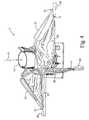
- FIG. 2shows a perspective view of an embodiment of the present invention in its collapsed configuration, corresponding to FIG. 1A .
- FIG. 3is an enlarged partial view of structure shown in FIG. 2 , particularly showing the rollers and arms used to restrain and guide the masts of the present invention. Elements of the structure have been deleted to facilitate understanding.
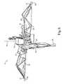
- FIG. 4shows a perspective view of the aforementioned embodiment of the present invention in the partial stage of deployment schematically shown in FIG. 1B .
- FIG. 5again provides the perspective view of the aforementioned embodiment shown partially deployed in FIG. 4 , but, in order to facilitate understanding, the flexible material, cords and spars have been deleted.
- FIG. 6shows a perspective view of the aforementioned embodiment of the present invention in the partial stage of deployment schematically shown in FIG. 1C .
- FIG. 7shows a perspective view of the aforementioned embodiment of the present invention in the partial stage of deployment schematically shown in FIG. 1D .
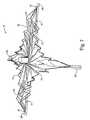
- FIG. 8shows a perspective view of the aforementioned embodiment of the present invention in its fully deployed configuration, as otherwise shown schematically in FIG. 1E .
- FIGS. 1A through 1Ecomprise a sequential series of schematic drawings showing the same top plan view of structure 11 , an embodiment of the present invention, wherein FIG. 1A initially shows structure 11 in its collapsed or stored configuration, followed by the interim stages of deployment shown in FIGS. 1B , 1 C, and 1 D, until full deployment is finally realized in FIG. 1E .
- FIG. 2A perspective view of structure 11 in its collapsed configuration, corresponding to FIG. 1A , is shown in FIG. 2 .
- a perspective view of structure 11 in the partial stage of deployment schematically shown in FIG. 1Bis illustrated in FIG. 4 .
- FIG. 6shows a perspective view of structure 11 in the partial stage of deployment schematically shown in FIG. 1C ;
- FIG. 7is perspective view of structure 11 corresponding to FIG. 1D ;
- FIG. 8is a perspective view of structure 11 fully deployed, corresponding to FIG. 1E .
- Structure 11includes cylindrical drum 13 having axis of rotation 15 about which it may rotate. Axis of rotation 15 is collinear with the axis of revolution of drum 13 . As most clearly shown the fully deployed configuration pictured in FIGS. 1E and 8 , structure 11 is further comprised of masts 17 , inner spar 19 , outer spar 21 , radial cords 23 and flexible material 25 . Mast 17 is comprised of proximal segment 27 and distal end 29 . Proximal segment 27 is attached to drum 13 . Outer spar 21 circumscribes drum 13 , and connects distal ends 29 . Outer spar 21 is attached to distal ends 29 by joints 31 .
- Inner spar 19also circumscribes drum 13 , and lies closer to drum 13 that outer spar 21 .
- Inner spar 19connects masts 17 at locations lying in between proximal segments 27 and distal ends 29 , respectively.
- Cords 23extend radially with respect to axis of rotation 15 , and connect inner spar 19 and outer spar 21 .
- Flexible material 25is attached to cords 23 .
- Mast 17is resilient and flexible about an axis parallel to axis of rotation 15 , and a bending stress is created in mast 17 when it is deformed from a linear configuration about the aforementioned axis. It is rigid about other axes.
- masts 17are wrapped around drum 13 .
- a restraintprevents the rotation of drum 13 by opposing the bending stress.
- the restraintmay be any mechanism commonly used to prevent rotation of a cylindrical object.
- rollers 33 and arms 35are in lateral and frictional contact with each mast 17 . They perform several functions when the restraint acting on drum 13 is disengaged to allow drum 13 freedom of rotation. Firstly, they oppose the bending stress and transfer this strain energy to drum 13 , causing it to rotate in a counterclockwise direction and thereby allow masts 17 to extend. The initial stage of extension and deployment is shown in FIGS. 1B and 4 . Secondly, the frictional resistance of rollers 33 and arms 35 is adjustable to control the rate at which masts 17 extend. Furthermore, rollers 33 laterally constrain masts 17 to provide equal spacing between adjacent masts in the fully deployed configuration. Inner spar 19 , outer spar 21 and cords 23 are in tension during this and subsequent stages of deployment.
- FIG. 5shows apparatus 11 in the same degree of partial deployment as FIG. 4 , but with inner spar 19 , outer spar 21 , radial cords 23 and flexible material 25 deleted in order to facilitate understanding.
- FIG. 1C and corresponding FIG. 6show further deployment and extension of masts 17 .
- FIG. 1D and corresponding FIG. 7illustrate the stage of deployment just before the complete deployment shown in FIGS. 1E and 6 is realized.
- Inner spar 19 , outer spar 21 and cords 23remain in tension when the complete deployment of masts 17 and structure 11 is realized.
- material 25depends upon the function of structure 11 . For example, if structure 11 was to be stored on a spacecraft for subsequent deployment as a solar sail, material 25 would be a thin membrane for reflecting the impact of photons and thereby providing a propulsive force.
- the present inventionuses no hinges or springs to assist in deploying material 25 . Only the strain energy stored in wrapping masts 17 around drum 13 is used to deploy the structure into the desired configuration. Thus, the present invention realizes the attendant benefits of enhanced reliability, improved mass efficiency, and minimizes the space required for storage.
Landscapes
- Engineering & Computer Science (AREA)
- Remote Sensing (AREA)
- Aviation & Aerospace Engineering (AREA)
- Life Sciences & Earth Sciences (AREA)
- Sustainable Development (AREA)
- Sustainable Energy (AREA)
- Chemical & Material Sciences (AREA)
- Combustion & Propulsion (AREA)
- Aerials With Secondary Devices (AREA)
Abstract
Description
Claims (19)
Priority Applications (1)
| Application Number | Priority Date | Filing Date | Title |
|---|---|---|---|
| US12/106,716US8356774B1 (en) | 2008-04-21 | 2008-04-21 | Structure for storing and unfurling a flexible material |
Applications Claiming Priority (1)
| Application Number | Priority Date | Filing Date | Title |
|---|---|---|---|
| US12/106,716US8356774B1 (en) | 2008-04-21 | 2008-04-21 | Structure for storing and unfurling a flexible material |
Publications (1)
| Publication Number | Publication Date |
|---|---|
| US8356774B1true US8356774B1 (en) | 2013-01-22 |
Family
ID=47521658
Family Applications (1)
| Application Number | Title | Priority Date | Filing Date |
|---|---|---|---|
| US12/106,716Active2032-04-28US8356774B1 (en) | 2008-04-21 | 2008-04-21 | Structure for storing and unfurling a flexible material |
Country Status (1)
| Country | Link |
|---|---|
| US (1) | US8356774B1 (en) |
Cited By (46)
| Publication number | Priority date | Publication date | Assignee | Title |
|---|---|---|---|---|
| US20130175401A1 (en)* | 2011-03-08 | 2013-07-11 | Astrium Gmbh | Salvaging and Braking Device for Objects Flying Freely in Space |
| US8646747B1 (en)* | 2011-07-11 | 2014-02-11 | Intellectual Ventures Fund 79 Llc | Methods, devices, and mediums associated with optical lift mechanism |
| US20140042275A1 (en)* | 2012-08-09 | 2014-02-13 | Analytical Mechanics Associates, Inc. | Gossamer apparatus and systems for use with spacecraft |
| CN104092005A (en)* | 2014-06-30 | 2014-10-08 | 中国空间技术研究院 | A Sunlight Pressure Acquisition Structure with Electromagnetic Wave Transceiver Capability |
| CN106114913A (en)* | 2016-08-12 | 2016-11-16 | 上海卫星工程研究所 | A Deep Space Probe Propelled by Massless Magneto-Optic Double-sail Combination |
| US9512618B2 (en) | 2013-11-20 | 2016-12-06 | Brigham Young University | Rigidly foldable array of three-dimensional bodies |
| CN106542121A (en)* | 2016-11-03 | 2017-03-29 | 上海卫星工程研究所 | Magneto-optic double sail compound propulsion system and method are damaged without matter for survey of deep space |
| CN106927067A (en)* | 2015-12-31 | 2017-07-07 | 中国科学院沈阳自动化研究所 | A kind of solar sail development mechanism |
| US9742348B2 (en) | 2013-09-16 | 2017-08-22 | Brigham Young University | Foldable array of three-dimensional panels including functional electrical components |
| ITUA20163982A1 (en)* | 2016-05-31 | 2017-12-01 | N P C New Production Concept S R L | AERODYNAMIC DEVICE FOR THE ORBITAL FALL OF A SATELLITE |
| WO2017221872A1 (en)* | 2016-06-21 | 2017-12-28 | 株式会社Qps研究所 | Expandable antenna |
| US9856039B2 (en)* | 2014-10-08 | 2018-01-02 | Analytical Mechanics Associates, Inc. | Extendable solar array for a spacecraft system |
| GB2555656A (en)* | 2016-11-08 | 2018-05-09 | Oxford Space Systems | Deployable wrapped rib assembly |
| US9970222B1 (en) | 2014-12-17 | 2018-05-15 | The United States Of America As Represented By The Secretary Of The Air Force | Compliant hinge for membrane-like structures |
| DE102017101178A1 (en) | 2017-01-23 | 2018-07-26 | Deutsches Zentrum für Luft- und Raumfahrt e.V. | A method of packing a spacecraft membrane, spacecraft membrane package, and spacecraft membrane handling unit |
| US10189583B2 (en)* | 2015-05-13 | 2019-01-29 | Analytical Mechanics Associates, Inc. | Deployable sheet material systems and methods |
| WO2019087236A1 (en)* | 2017-10-30 | 2019-05-09 | 株式会社Qps研究所 | Reflector, developed antenna, and aerospace vehicle |
| US10435184B2 (en) | 2016-05-06 | 2019-10-08 | Darrin Taylor | Method of space travel using a high acceleration thrust vehicle in combination with a plurality of low acceleration thrust vehicles |
| CN110723314A (en)* | 2019-10-12 | 2020-01-24 | 上海宇航系统工程研究所 | Space film structure unfolding mechanism |
| US20200130868A1 (en)* | 2018-10-31 | 2020-04-30 | California Institute Of Technology | Actively Controlled Spacecraft Deployment Mechanism |
| US10715078B2 (en) | 2017-03-22 | 2020-07-14 | Sungeun K. Jeon | Compact, self-deploying structures and methods for deploying foldable, structural origami arrays of photovoltaic modules, solar sails, and antenna structures |
| WO2020150735A1 (en)* | 2019-01-18 | 2020-07-23 | M.M.A. Design, LLC | Deployable system with flexible membrane |
| US10763569B2 (en) | 2013-09-06 | 2020-09-01 | M.M.A. Design, LLC | Deployable reflectarray antenna structure |
| US10773833B1 (en) | 2011-08-30 | 2020-09-15 | MMA Design, LLC | Panel for use in a deployable and cantilevered solar array structure |
| US10797400B1 (en) | 2019-03-14 | 2020-10-06 | Eagle Technology, Llc | High compaction ratio reflector antenna with offset optics |
| CN111746825A (en)* | 2020-07-06 | 2020-10-09 | 哈尔滨工业大学 | Deformable shading structure and aerospace device |
| US10811759B2 (en) | 2018-11-13 | 2020-10-20 | Eagle Technology, Llc | Mesh antenna reflector with deployable perimeter |
| WO2020223733A1 (en)* | 2019-05-02 | 2020-11-05 | L'garde, Inc. | Solar sail attachment and deployment methods |
| US10971793B2 (en) | 2015-09-25 | 2021-04-06 | M.M.A. Design, LLC | Deployable structure for use in establishing a reflectarray antenna |
| US10994868B2 (en)* | 2017-10-18 | 2021-05-04 | Frank Werner Ellinghaus | PanelSat—stack able satellite with fuel free attitude control |
| US11009695B2 (en)* | 2017-01-17 | 2021-05-18 | Tendeg Llc | Occulter petal unfurling system |
| US11139549B2 (en) | 2019-01-16 | 2021-10-05 | Eagle Technology, Llc | Compact storable extendible member reflector |
| US11239567B2 (en) | 2019-05-08 | 2022-02-01 | Tendeg Llc | Antenna |
| CN114030937A (en)* | 2021-11-30 | 2022-02-11 | 北京新风航天装备有限公司 | Electric folding device for large flexible product |
| USD947761S1 (en)* | 2021-03-13 | 2022-04-05 | Leala Nakagawa | Retractable structural template |
| US11634240B2 (en) | 2018-07-17 | 2023-04-25 | California Institute Of Technology | Coilable thin-walled longerons and coilable structures implementing longerons and methods for their manufacture and coiling |
| US20230220940A1 (en)* | 2022-01-07 | 2023-07-13 | Inventions, Plus LLC | Disk with adjustable outer diameter |
| US11901629B2 (en) | 2021-09-30 | 2024-02-13 | Eagle Technology, Llc | Deployable antenna reflector |
| US11949161B2 (en) | 2021-08-27 | 2024-04-02 | Eagle Technology, Llc | Systems and methods for making articles comprising a carbon nanotube material |
| US11990665B2 (en) | 2021-08-04 | 2024-05-21 | M.M.A. Design, LLC | Multi-direction deployable antenna |
| US20240270412A1 (en)* | 2021-08-27 | 2024-08-15 | Space Forge Limited | Spacecraft Heat Shield |
| CN118637076A (en)* | 2024-05-31 | 2024-09-13 | 苏州大学 | A curved elastic expansion rod type membrane structure |
| US12145750B2 (en) | 2018-02-15 | 2024-11-19 | L'garde, Inc. | Space debris engagement and deorbit system |
| US12409953B2 (en) | 2020-02-24 | 2025-09-09 | L'garde, Inc. | Connection assembly |
| US12431607B2 (en) | 2016-02-29 | 2025-09-30 | L'garde, Inc. | Compactable RF membrane antenna |
| US12444826B2 (en) | 2024-03-25 | 2025-10-14 | L'garde, Inc. | Compactable structures for deployment in space |
Citations (12)
| Publication number | Priority date | Publication date | Assignee | Title |
|---|---|---|---|---|
| US1833004A (en)* | 1929-10-03 | 1931-11-24 | Walter J Spiro | Folding umbrella |
| US1943748A (en)* | 1931-09-03 | 1934-01-16 | United Eng Foundry Co | Apparatus for uncoiling metal strip |
| US2942794A (en) | 1957-03-04 | 1960-06-28 | Maurice A Huso | Sheet reel |
| US3217328A (en) | 1963-03-08 | 1965-11-09 | Electro Optical Systems Inc | Antenna with wire mesh reflector collapsing in a pinwheel manner |
| US3576566A (en) | 1966-10-31 | 1971-04-27 | Hughes Aircraft Co | Closed loop antenna reflector supporting structure |
| US3848821A (en)* | 1971-08-30 | 1974-11-19 | H Scheel | Space-saving storage of flexible sheets |
| US4030102A (en) | 1975-10-23 | 1977-06-14 | Grumman Aerospace Corporation | Deployable reflector structure |
| US4614319A (en) | 1980-05-05 | 1986-09-30 | Drexler Kim E | Solar sail |
| US4683475A (en)* | 1981-07-02 | 1987-07-28 | Luly Robert A | Folding dish reflector |
| US5296044A (en) | 1992-03-06 | 1994-03-22 | Aec-Able Engineering Company, Inc. | Lightweight stowable and deployable solar cell array |
| US5446474A (en) | 1994-01-19 | 1995-08-29 | Lockheed Missiles & Space Company, Inc. | Redeployable furlable rib reflector |
| US6689952B2 (en) | 2001-07-16 | 2004-02-10 | The Director-General Of The Institute Of Space And Astronautical Science | Large membrane space structure and method for its deployment and expansion |
- 2008
- 2008-04-21USUS12/106,716patent/US8356774B1/enactiveActive
Patent Citations (12)
| Publication number | Priority date | Publication date | Assignee | Title |
|---|---|---|---|---|
| US1833004A (en)* | 1929-10-03 | 1931-11-24 | Walter J Spiro | Folding umbrella |
| US1943748A (en)* | 1931-09-03 | 1934-01-16 | United Eng Foundry Co | Apparatus for uncoiling metal strip |
| US2942794A (en) | 1957-03-04 | 1960-06-28 | Maurice A Huso | Sheet reel |
| US3217328A (en) | 1963-03-08 | 1965-11-09 | Electro Optical Systems Inc | Antenna with wire mesh reflector collapsing in a pinwheel manner |
| US3576566A (en) | 1966-10-31 | 1971-04-27 | Hughes Aircraft Co | Closed loop antenna reflector supporting structure |
| US3848821A (en)* | 1971-08-30 | 1974-11-19 | H Scheel | Space-saving storage of flexible sheets |
| US4030102A (en) | 1975-10-23 | 1977-06-14 | Grumman Aerospace Corporation | Deployable reflector structure |
| US4614319A (en) | 1980-05-05 | 1986-09-30 | Drexler Kim E | Solar sail |
| US4683475A (en)* | 1981-07-02 | 1987-07-28 | Luly Robert A | Folding dish reflector |
| US5296044A (en) | 1992-03-06 | 1994-03-22 | Aec-Able Engineering Company, Inc. | Lightweight stowable and deployable solar cell array |
| US5446474A (en) | 1994-01-19 | 1995-08-29 | Lockheed Missiles & Space Company, Inc. | Redeployable furlable rib reflector |
| US6689952B2 (en) | 2001-07-16 | 2004-02-10 | The Director-General Of The Institute Of Space And Astronautical Science | Large membrane space structure and method for its deployment and expansion |
Non-Patent Citations (5)
| Title |
|---|
| Banik, J., & Murphey, T., "Synchronous Deployed Solar Sail Subsystem Design Concept," Proceedings of the 48th AIAA Structures, Structural Dynamics, and Materials Conference, AIAA-2007-1837, Honolulu, Hawaii, 13 pages (Apr. 23-26, 2007). |
| Banik, J., Murphey, T., & Dumm, H., "Synchronus Deployed Solar Sail Concept Demonstration," Proceedings of the 49th AIAA Structures, Structural Dynamics, and Materials Conference, AIAA-2008-2213, Schaumburg, Illinois, 9 pages (Apr. 10, 2008). |
| Leipold, M., et al., "Odissee-A proposal for Demonstration of a Solar Sail in Earth Orbit," Proceedings of the European Conference on Spacecraft Structures, Materials and Mechanical Testing, Braunschweig, Germany, pp. 245-255 (Nov. 4-6, 1998). |
| Salama, M., White, C., & Leland, R., "Ground Demonstration of a Spinning Solar Sail Deployment Concept," Journal of Spacecraft and Rocketsvol. 40, No. 1, pp. 9-14 (Jan.-Feb. 2003). |
| Shultz, M., & Pellegrino, S., "Equilibrium paths of mechanical systems with unilateral constraints II. Deployable reflector," Proc. R. Soc. Lond. A, vol. 456, pp. 2243-2262 (2000). |
Cited By (70)
| Publication number | Priority date | Publication date | Assignee | Title |
|---|---|---|---|---|
| US9022323B2 (en)* | 2011-03-08 | 2015-05-05 | Astrium Gmbh | Salvaging and braking device for objects flying freely in space |
| US20130175401A1 (en)* | 2011-03-08 | 2013-07-11 | Astrium Gmbh | Salvaging and Braking Device for Objects Flying Freely in Space |
| US8646747B1 (en)* | 2011-07-11 | 2014-02-11 | Intellectual Ventures Fund 79 Llc | Methods, devices, and mediums associated with optical lift mechanism |
| US9033304B2 (en) | 2011-07-11 | 2015-05-19 | Intellectual Ventures Fund 79 Llc | Methods, devices, and mediums associated with optical lift mechanism |
| US10773833B1 (en) | 2011-08-30 | 2020-09-15 | MMA Design, LLC | Panel for use in a deployable and cantilevered solar array structure |
| US9555904B2 (en)* | 2012-08-09 | 2017-01-31 | Analytical Mechanics Associates, Inc. | Gossamer apparatus and systems for use with spacecraft |
| US20140042275A1 (en)* | 2012-08-09 | 2014-02-13 | Analytical Mechanics Associates, Inc. | Gossamer apparatus and systems for use with spacecraft |
| US10826157B2 (en) | 2013-09-06 | 2020-11-03 | MMA Design, LLC | Deployable reflectarray antenna structure |
| US11901605B2 (en) | 2013-09-06 | 2024-02-13 | M.M.A. Design, LLC | Deployable antenna structure |
| US10763569B2 (en) | 2013-09-06 | 2020-09-01 | M.M.A. Design, LLC | Deployable reflectarray antenna structure |
| US9742348B2 (en) | 2013-09-16 | 2017-08-22 | Brigham Young University | Foldable array of three-dimensional panels including functional electrical components |
| US9512618B2 (en) | 2013-11-20 | 2016-12-06 | Brigham Young University | Rigidly foldable array of three-dimensional bodies |
| CN104092005A (en)* | 2014-06-30 | 2014-10-08 | 中国空间技术研究院 | A Sunlight Pressure Acquisition Structure with Electromagnetic Wave Transceiver Capability |
| US9856039B2 (en)* | 2014-10-08 | 2018-01-02 | Analytical Mechanics Associates, Inc. | Extendable solar array for a spacecraft system |
| US9970222B1 (en) | 2014-12-17 | 2018-05-15 | The United States Of America As Represented By The Secretary Of The Air Force | Compliant hinge for membrane-like structures |
| US10815012B2 (en)* | 2015-05-13 | 2020-10-27 | Analytical Mechanics Associates, Inc. | Deployable sheet material systems and methods |
| US10189583B2 (en)* | 2015-05-13 | 2019-01-29 | Analytical Mechanics Associates, Inc. | Deployable sheet material systems and methods |
| US20190263540A1 (en)* | 2015-05-13 | 2019-08-29 | Analytical Mechanics Associates, Inc. | Deployable sheet material systems and methods |
| US10971793B2 (en) | 2015-09-25 | 2021-04-06 | M.M.A. Design, LLC | Deployable structure for use in establishing a reflectarray antenna |
| CN106927067A (en)* | 2015-12-31 | 2017-07-07 | 中国科学院沈阳自动化研究所 | A kind of solar sail development mechanism |
| US12431607B2 (en) | 2016-02-29 | 2025-09-30 | L'garde, Inc. | Compactable RF membrane antenna |
| US10435184B2 (en) | 2016-05-06 | 2019-10-08 | Darrin Taylor | Method of space travel using a high acceleration thrust vehicle in combination with a plurality of low acceleration thrust vehicles |
| ITUA20163982A1 (en)* | 2016-05-31 | 2017-12-01 | N P C New Production Concept S R L | AERODYNAMIC DEVICE FOR THE ORBITAL FALL OF A SATELLITE |
| JPWO2017221872A1 (en)* | 2016-06-21 | 2019-04-11 | 株式会社Qps研究所 | Deployment antenna |
| US11223139B2 (en) | 2016-06-21 | 2022-01-11 | Institute For Q-Shu Pioneers Of Space, Inc. | Expandable antenna |
| WO2017221872A1 (en)* | 2016-06-21 | 2017-12-28 | 株式会社Qps研究所 | Expandable antenna |
| CN106114913A (en)* | 2016-08-12 | 2016-11-16 | 上海卫星工程研究所 | A Deep Space Probe Propelled by Massless Magneto-Optic Double-sail Combination |
| CN106542121A (en)* | 2016-11-03 | 2017-03-29 | 上海卫星工程研究所 | Magneto-optic double sail compound propulsion system and method are damaged without matter for survey of deep space |
| GB2555656A (en)* | 2016-11-08 | 2018-05-09 | Oxford Space Systems | Deployable wrapped rib assembly |
| US11009695B2 (en)* | 2017-01-17 | 2021-05-18 | Tendeg Llc | Occulter petal unfurling system |
| DE102017101178B4 (en) | 2017-01-23 | 2021-10-28 | Deutsches Zentrum für Luft- und Raumfahrt e.V. | A method of packaging a spacecraft membrane, spacecraft membrane package, and spacecraft membrane handling unit |
| DE102017101178A1 (en) | 2017-01-23 | 2018-07-26 | Deutsches Zentrum für Luft- und Raumfahrt e.V. | A method of packing a spacecraft membrane, spacecraft membrane package, and spacecraft membrane handling unit |
| US10715078B2 (en) | 2017-03-22 | 2020-07-14 | Sungeun K. Jeon | Compact, self-deploying structures and methods for deploying foldable, structural origami arrays of photovoltaic modules, solar sails, and antenna structures |
| US10994868B2 (en)* | 2017-10-18 | 2021-05-04 | Frank Werner Ellinghaus | PanelSat—stack able satellite with fuel free attitude control |
| CN111279554A (en)* | 2017-10-30 | 2020-06-12 | 株式会社Qps研究所 | Reflector, unfolding antenna and spacecraft |
| WO2019087236A1 (en)* | 2017-10-30 | 2019-05-09 | 株式会社Qps研究所 | Reflector, developed antenna, and aerospace vehicle |
| US11381001B2 (en) | 2017-10-30 | 2022-07-05 | Institute For Q-Shu Pioneers Of Space, Inc. | Reflector, deployable antenna, and spacecraft |
| EP3706245A4 (en)* | 2017-10-30 | 2021-06-23 | Institute for Q-shu Pioneers of Space, Inc. | REFLECTOR, DEVELOPED ANTENNA AND AEROSPACE VEHICLE |
| US12145750B2 (en) | 2018-02-15 | 2024-11-19 | L'garde, Inc. | Space debris engagement and deorbit system |
| US11634240B2 (en) | 2018-07-17 | 2023-04-25 | California Institute Of Technology | Coilable thin-walled longerons and coilable structures implementing longerons and methods for their manufacture and coiling |
| US11772826B2 (en)* | 2018-10-31 | 2023-10-03 | California Institute Of Technology | Actively controlled spacecraft deployment mechanism |
| US20200130868A1 (en)* | 2018-10-31 | 2020-04-30 | California Institute Of Technology | Actively Controlled Spacecraft Deployment Mechanism |
| US10811759B2 (en) | 2018-11-13 | 2020-10-20 | Eagle Technology, Llc | Mesh antenna reflector with deployable perimeter |
| US11139549B2 (en) | 2019-01-16 | 2021-10-05 | Eagle Technology, Llc | Compact storable extendible member reflector |
| US11862840B2 (en) | 2019-01-16 | 2024-01-02 | Eagle Technologies, Llc | Compact storable extendible member reflector |
| WO2020150735A1 (en)* | 2019-01-18 | 2020-07-23 | M.M.A. Design, LLC | Deployable system with flexible membrane |
| US12227310B2 (en) | 2019-01-18 | 2025-02-18 | M.M.A. Design, LLC | Deployable system with flexible membrane |
| US20200231308A1 (en)* | 2019-01-18 | 2020-07-23 | M.M.A. Design, LLC | Deployable System with Flexible Membrane |
| US11724828B2 (en)* | 2019-01-18 | 2023-08-15 | M.M.A. Design, LLC | Deployable system with flexible membrane |
| US10797400B1 (en) | 2019-03-14 | 2020-10-06 | Eagle Technology, Llc | High compaction ratio reflector antenna with offset optics |
| WO2020223733A1 (en)* | 2019-05-02 | 2020-11-05 | L'garde, Inc. | Solar sail attachment and deployment methods |
| EP3962815A4 (en)* | 2019-05-02 | 2023-01-18 | L'garde, Inc. | Solar sail attachment and deployment methods |
| US12084207B2 (en) | 2019-05-02 | 2024-09-10 | L'garde, Inc. | Solar sail attachment and deployment methods |
| US11749898B2 (en) | 2019-05-08 | 2023-09-05 | Tendeg Llc | Antenna |
| US11239567B2 (en) | 2019-05-08 | 2022-02-01 | Tendeg Llc | Antenna |
| CN110723314A (en)* | 2019-10-12 | 2020-01-24 | 上海宇航系统工程研究所 | Space film structure unfolding mechanism |
| US12409953B2 (en) | 2020-02-24 | 2025-09-09 | L'garde, Inc. | Connection assembly |
| CN111746825A (en)* | 2020-07-06 | 2020-10-09 | 哈尔滨工业大学 | Deformable shading structure and aerospace device |
| USD947761S1 (en)* | 2021-03-13 | 2022-04-05 | Leala Nakagawa | Retractable structural template |
| US11990665B2 (en) | 2021-08-04 | 2024-05-21 | M.M.A. Design, LLC | Multi-direction deployable antenna |
| US11949161B2 (en) | 2021-08-27 | 2024-04-02 | Eagle Technology, Llc | Systems and methods for making articles comprising a carbon nanotube material |
| US20240270412A1 (en)* | 2021-08-27 | 2024-08-15 | Space Forge Limited | Spacecraft Heat Shield |
| US12208928B2 (en)* | 2021-08-27 | 2025-01-28 | Space Forge Limited | Spacecraft heat shield |
| US11901629B2 (en) | 2021-09-30 | 2024-02-13 | Eagle Technology, Llc | Deployable antenna reflector |
| CN114030937A (en)* | 2021-11-30 | 2022-02-11 | 北京新风航天装备有限公司 | Electric folding device for large flexible product |
| CN114030937B (en)* | 2021-11-30 | 2023-09-08 | 北京新风航天装备有限公司 | Large-scale flexible product electric folding device |
| US20230220940A1 (en)* | 2022-01-07 | 2023-07-13 | Inventions, Plus LLC | Disk with adjustable outer diameter |
| US12444826B2 (en) | 2024-03-25 | 2025-10-14 | L'garde, Inc. | Compactable structures for deployment in space |
| CN118637076A (en)* | 2024-05-31 | 2024-09-13 | 苏州大学 | A curved elastic expansion rod type membrane structure |
| CN118637076B (en)* | 2024-05-31 | 2025-08-12 | 苏州大学 | A curved elastic expansion rod type membrane structure |
Similar Documents
| Publication | Publication Date | Title |
|---|---|---|
| US8356774B1 (en) | Structure for storing and unfurling a flexible material | |
| US9676501B1 (en) | Space solar array architecture for ultra-high power applications | |
| US20240025568A1 (en) | Space debris engagement and deorbit system | |
| US9346566B2 (en) | Directionally controlled elastically deployable roll-out array | |
| Leipold et al. | Solar sail technology development and demonstration | |
| US9550584B1 (en) | Deployable thin membrane apparatus | |
| US9611056B1 (en) | Directionally controlled elastically deployable roll-out solar array | |
| Fernandez et al. | Completely stripped solar sail concept using bi-stable reeled composite booms | |
| US9079673B1 (en) | Assembly for collecting electromagnetic energy | |
| Pellegrino | Large retractable appendages in spacecraft | |
| US8770522B1 (en) | Deployable space boom using bi-stable tape spring mechanism | |
| US20070262204A1 (en) | Large-Scale Deployable Solar Array | |
| US20200055618A1 (en) | Deployable sheet material systems and methods | |
| US6508036B1 (en) | Method of linear actuation by inflation and apparatus therefor | |
| US20120167943A1 (en) | Unwindable Flat Solar Generator | |
| US20080111031A1 (en) | Deployable flat membrane structure | |
| US3978490A (en) | Furlable antenna | |
| Lin et al. | Shape memory rigidizable inflatable (RI) structures for large space systems applications | |
| JP4876941B2 (en) | Deployable antenna | |
| US11958637B2 (en) | Gyromesh solar sail spacecraft and sail panel assemblies | |
| Straubel et al. | Deployable composite booms for various gossamer space structures | |
| WO2016051141A1 (en) | Deployable structure | |
| JP6448293B2 (en) | Structural member deployment system | |
| Gross et al. | The Able deployable articulated mast—enabling technology for the Shuttle Radar Topography Mission | |
| Mobrem et al. | Design and performance of the telescopic tubular mast |
Legal Events
| Date | Code | Title | Description |
|---|---|---|---|
| AS | Assignment | Owner name:THE GOVERNMENT OF THE UNITED STATES AS REPRESENTED Free format text:ASSIGNMENT OF ASSIGNORS INTEREST;ASSIGNORS:MURPHEY, THOMAS W.;BANIK, JEREMY A.;CSA ENGINEERING, INC.;REEL/FRAME:020834/0165 Effective date:20080421 | |
| STCF | Information on status: patent grant | Free format text:PATENTED CASE | |
| FPAY | Fee payment | Year of fee payment:4 | |
| FEPP | Fee payment procedure | Free format text:7.5 YR SURCHARGE - LATE PMT W/IN 6 MO, LARGE ENTITY (ORIGINAL EVENT CODE: M1555); ENTITY STATUS OF PATENT OWNER: LARGE ENTITY | |
| MAFP | Maintenance fee payment | Free format text:PAYMENT OF MAINTENANCE FEE, 8TH YEAR, LARGE ENTITY (ORIGINAL EVENT CODE: M1552); ENTITY STATUS OF PATENT OWNER: LARGE ENTITY Year of fee payment:8 | |
| FEPP | Fee payment procedure | Free format text:MAINTENANCE FEE REMINDER MAILED (ORIGINAL EVENT CODE: REM.); ENTITY STATUS OF PATENT OWNER: LARGE ENTITY | |
| FEPP | Fee payment procedure | Free format text:11.5 YR SURCHARGE- LATE PMT W/IN 6 MO, LARGE ENTITY (ORIGINAL EVENT CODE: M1556); ENTITY STATUS OF PATENT OWNER: LARGE ENTITY | |
| MAFP | Maintenance fee payment | Free format text:PAYMENT OF MAINTENANCE FEE, 12TH YEAR, LARGE ENTITY (ORIGINAL EVENT CODE: M1553); ENTITY STATUS OF PATENT OWNER: LARGE ENTITY Year of fee payment:12 |