US8356431B2 - Scheduling communication frames in a wireless network - Google Patents
Scheduling communication frames in a wireless networkDownload PDFInfo
- Publication number
- US8356431B2 US8356431B2US12/101,074US10107408AUS8356431B2US 8356431 B2US8356431 B2US 8356431B2US 10107408 AUS10107408 AUS 10107408AUS 8356431 B2US8356431 B2US 8356431B2
- Authority
- US
- United States
- Prior art keywords
- network
- superframe
- network device
- timeslots
- timeslot
- Prior art date
- Legal status (The legal status is an assumption and is not a legal conclusion. Google has not performed a legal analysis and makes no representation as to the accuracy of the status listed.)
- Active, expires
Links
- 238000004891communicationMethods0.000titleclaimsabstractdescription158
- 238000000034methodMethods0.000claimsabstractdescription99
- 230000008569processEffects0.000claimsdescription43
- 238000004886process controlMethods0.000claimsdescription42
- 230000005540biological transmissionEffects0.000claimsdescription33
- 238000005259measurementMethods0.000claimsdescription28
- 230000006870functionEffects0.000claimsdescription18
- 230000004044responseEffects0.000claimsdescription12
- 230000001052transient effectEffects0.000claimsdescription11
- 239000012634fragmentSubstances0.000claimsdescription5
- 230000002618waking effectEffects0.000claimsdescription3
- 230000009849deactivationEffects0.000claims1
- 238000005516engineering processMethods0.000description12
- 230000007704transitionEffects0.000description10
- 230000008901benefitEffects0.000description9
- 238000001228spectrumMethods0.000description9
- 238000007726management methodMethods0.000description7
- 238000012544monitoring processMethods0.000description5
- 230000008859changeEffects0.000description4
- 238000010586diagramMethods0.000description4
- 230000000694effectsEffects0.000description4
- 238000009434installationMethods0.000description4
- 238000012423maintenanceMethods0.000description4
- 230000002159abnormal effectEffects0.000description3
- 238000013459approachMethods0.000description3
- QVGXLLKOCUKJST-UHFFFAOYSA-Natomic oxygenChemical compound[O]QVGXLLKOCUKJST-UHFFFAOYSA-N0.000description3
- 230000036541healthEffects0.000description3
- 239000001301oxygenSubstances0.000description3
- 229910052760oxygenInorganic materials0.000description3
- 239000000126substanceSubstances0.000description3
- 230000001360synchronised effectEffects0.000description3
- 238000012546transferMethods0.000description3
- QGZKDVFQNNGYKY-UHFFFAOYSA-NAmmoniaChemical compoundNQGZKDVFQNNGYKY-UHFFFAOYSA-N0.000description2
- 235000008694Humulus lupulusNutrition0.000description2
- 150000001875compoundsChemical class0.000description2
- 230000006855networkingEffects0.000description2
- 230000000644propagated effectEffects0.000description2
- 230000001902propagating effectEffects0.000description2
- 238000013468resource allocationMethods0.000description2
- 238000012549trainingMethods0.000description2
- 238000013519translationMethods0.000description2
- 238000012384transportation and deliveryMethods0.000description2
- XLYOFNOQVPJJNP-UHFFFAOYSA-NwaterSubstancesOXLYOFNOQVPJJNP-UHFFFAOYSA-N0.000description2
- WQZGKKKJIJFFOK-GASJEMHNSA-NGlucoseNatural productsOC[C@H]1OC(O)[C@H](O)[C@@H](O)[C@@H]1OWQZGKKKJIJFFOK-GASJEMHNSA-N0.000description1
- 101100172132Mus musculus Eif3a geneProteins0.000description1
- 230000009471actionEffects0.000description1
- 230000002776aggregationEffects0.000description1
- 238000004220aggregationMethods0.000description1
- 238000004378air conditioningMethods0.000description1
- 229910021529ammoniaInorganic materials0.000description1
- 238000013475authorizationMethods0.000description1
- 230000009286beneficial effectEffects0.000description1
- 238000006243chemical reactionMethods0.000description1
- 239000003153chemical reaction reagentSubstances0.000description1
- 230000000295complement effectEffects0.000description1
- 230000002498deadly effectEffects0.000description1
- 238000011161developmentMethods0.000description1
- 238000013154diagnostic monitoringMethods0.000description1
- 238000005538encapsulationMethods0.000description1
- 230000002708enhancing effectEffects0.000description1
- 238000004880explosionMethods0.000description1
- 238000005562fadingMethods0.000description1
- 238000007667floatingMethods0.000description1
- 239000007789gasSubstances0.000description1
- 239000008103glucoseSubstances0.000description1
- 231100001261hazardousToxicity0.000description1
- 238000010348incorporationMethods0.000description1
- 230000002401inhibitory effectEffects0.000description1
- 238000007689inspectionMethods0.000description1
- 238000005192partitionMethods0.000description1
- 230000000737periodic effectEffects0.000description1
- 239000003208petroleumSubstances0.000description1
- 238000004801process automationMethods0.000description1
- 230000035755proliferationEffects0.000description1
- 230000009467reductionEffects0.000description1
- 238000009420retrofittingMethods0.000description1
- 230000000630rising effectEffects0.000description1
- 238000013024troubleshootingMethods0.000description1
- 238000011144upstream manufacturingMethods0.000description1
Images


Classifications
- H—ELECTRICITY
- H04—ELECTRIC COMMUNICATION TECHNIQUE
- H04W—WIRELESS COMMUNICATION NETWORKS
- H04W84/00—Network topologies
- H04W84/18—Self-organising networks, e.g. ad-hoc networks or sensor networks
- H—ELECTRICITY
- H04—ELECTRIC COMMUNICATION TECHNIQUE
- H04J—MULTIPLEX COMMUNICATION
- H04J4/00—Combined time-division and frequency-division multiplex systems
- H—ELECTRICITY
- H04—ELECTRIC COMMUNICATION TECHNIQUE
- H04W—WIRELESS COMMUNICATION NETWORKS
- H04W72/00—Local resource management
- H04W72/12—Wireless traffic scheduling
Definitions
- the present inventionrelates generally to wireless communications and, more particularly, to scheduling communication frames in a wireless network.
- HARTHighway Addressable Remote Transmitter
- the HART protocolsupports a combined digital and analog signal on a dedicated wire or set of wires, in which on-line process signals (such as control signals, sensor measurements, etc.) are provided as an analog current signal (e.g., ranging from 4 to 20 milliamps) and in which other signals, such as device data, requests for device data, configuration data, alarm and event data, etc., are provided as digital signals superimposed or multiplexed onto the same wire or set of wires as the analog signal.
- on-line process signalssuch as control signals, sensor measurements, etc.
- analog current signale.g., ranging from 4 to 20 milliamps
- other signalssuch as device data, requests for device data, configuration data, alarm and event data, etc.
- wireless networkscannot easily extend wired networks.
- An additional challenge particularly pertinent to the process control industryis the high cost of the existing wired installations and the understandable reluctance of the operators to completely replace the wired infrastructure with a wireless infrastructure.
- wireless networkstypically require stationary antennas or access points to transmit and receive radio signals and may therefore require an expensive infrastructure which makes the transition to wireless communications less desirable.
- Another factor contributing to the slower than expected proliferation of wireless standards in the process control industryis the impact on a user, such as a technician or an operator of a process control system.
- usersmay remotely access individual devices for the purposes of configuring, monitoring, and controlling various functions of the devices.
- devicesare assigned unique addresses according to a predefined addressing scheme.
- Users and the software applications developed for operators and technicians in the process control industryhave come to rely on an efficient addressing scheme which cannot be supported by the available wireless standards.
- a transition to a wireless standard in a process control industryis widely expected to entail adopting a new addressing scheme, updating the corresponding software applications and providing additional training to the personnel.
- some of the existing wireless standardsdo not satisfy all of the demands of the process control industry.
- devicescommunicate both process and control data which may typically have different propagation delay constraints.
- some of the critical data exchanged in the process control industrymay require efficient, reliable and timely delivery which cannot always be guaranteed by the existing wireless protocols.
- wireless standards suitable for this industryneed to provide redundancy in communication paths not readily available in the known wireless networks.
- process control devicesmay be sensitive to high power radio signals and may require radio transmissions to be limited or held at a well controlled power level.
- the available wireless standardstypically rely on antennas or access points which transmit relatively strong signals to cover large geographic areas.
- wireless communication protocolsare expected to provide efficient, reliable and secure methods of exchanging information.
- much of the methodology developed to address these concerns on wired networksdoes not apply to wireless communications because of the shared and open nature of the medium.
- wireless protocolsface other requirements with respect to the issues of interference and co-existence of several networks that use the same part of the radio frequency spectrum.
- some wireless networksoperate in the part of the spectrum that is unlicensed, or open to the public. Therefore, protocols servicing such networks must be capable of detecting and resolving issues related to frequency (channel) contention, radio resource sharing and negotiation, etc.
- the process control industryrequires that the communication protocol servicing a particular process control network be able to accommodate field devices with different data transmission requirements, priorities, and power capabilities.
- some process control systemsmay include measurement devices that frequently (such as several times per second) report measurements to a centralized controller or to another field device. Meanwhile, another device in the same system may report measurements, alarms, or other data only once per hour.
- both devicesmay require that the respective measurement reports propagate to a destination host, such as a controller, a workstation, or a peer field device, with as little overhead in time and bandwidth as possible.
- a wireless mesh network for use in, for example, process control plantsincludes a plurality of network devices communicating according to a network schedule defined as a set of concurrent overlapping superframes.
- Each of the superframesincludes several communication timeslots of a predetermined time duration and each superframe repeats immediately after the occurrence of all communication timeslots in the superframe.
- the total number of timeslots in each superframedefines the length of the superframe and each particular timeslot has a relative timeslot number that corresponds to the number of timeslots existing in the superframe prior to the particular timeslot.
- each timeslotincludes a transmission time segment during which one or more network devices transmit data and an acknowledgement segment during which one or more network devices send an acknowledgement corresponding to the transmitted data.
- a network devicefurther performs Clear Channel Assessment to ascertain whether a particular shared timeslot is available for transmission.
- each superframemay correspond to a transmission requirement of a particular network device.
- a dedicated servicedefines superframes and allocates timeslots within each of the superframes according to the needs of network devices and of external hosts communicating with the network devices.
- the dedicated serviceassociates a network device with one or more timeslots of a particular superframe so that the network device may transmit or receive data during each occurrence of the timeslot.
- a network devicemay participate in multiple superframes to transmit data specific to the network device and to forward data between other network devices.
- the dedicated servicemay dynamically create and destroy superframes in view of changes in network conditions such as data bursts, congestion, block transfers, and network devices entering or leaving the network. Moreover, a network device or the dedicated service may efficiently deactivate a superframe without destroying the superframe by issuing a particular command.
- the dedicated servicemay be a software entity running on a dedicated physical host, or the dedicated service may run on a gateway device connecting the wireless mesh network to an external network or host.
- the network schedulemay include multiple communication channels and, in some embodiments, each communication channel may correspond to a unique carrier radio frequency.
- Each network devicemay have an individual schedule that includes relative timeslot numbers and communication channel identifiers and the individual schedule may specify the individually scheduled timeslots that the network device uses to transmit process data, route data originated from another network device, receive device-specific data, or receive broadcast data.
- the individual schedule for a network devicemay specify a timeslot associated with several distinct communication channels during different superframe cycles, so that the network device transmits or receives data over different communication channels within a timeslot having the same relative slot number of a particular superframe.
- the network devicein accordance with a corresponding individual schedule, iterates through several channels associated with a particular timeslot in a predefined manner. In other embodiments, the network schedule does not allocate different communication channels to the same timeslot.
- the dedicated servicemay create long superframes for a transient device that periodically wakes up according to a predefined schedule, thereby eliminating the need for the transient device to negotiate resources for each transmission session.
- the transient deviceconserves power by transmitting data only according to the necessary update rate of the transient device.
- At least some of the network devicesare field devices performing a measurement or control functions in a process control environment.
- Each of these field devicesis provisioned with a particular update rate, or frequency of communicating process data to another network device.
- the dedicated servicedefines superframes according to the update rates of the field devices.
- a field devicecan negotiate a temporary change in timeslot allocation due to an occurrence of a transient condition requiring a higher-than-normal or lower-than-normal bandwidth.
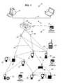
- FIG. 1is a block diagram that illustrates a system utilizing a WirelessHART network to provide wireless communication between field devices and router devices, which are connected to a plant automation network via a gateway device.
- FIG. 2is a schematic representation of the layers of a WirelessHART protocol implemented in accordance with one of the embodiments discussed herein.
- FIG. 3is a block diagram that illustrates segments of a communication timeslot defined in accordance with one of the embodiments discussed herein.
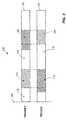
- FIG. 4is a block diagram that illustrates an exemplary association of timeslots of a three-slot superframe with several communicating devices.
- FIG. 5schematically illustrates association of a timeslot of an exemplary superframe with several communication channels.
- FIG. 6is a block diagram that schematically illustrates an exemplary superframe definition including several concurrent superframes of different length.
- FIG. 7illustrates an exemplary system in which several devices participate in a wireless network utilizing the scheduling techniques discussed herein.
- FIG. 8is an exemplary procedure which a network manager may execute to service a wireless network utilizing the scheduling techniques discussed herein.
- FIG. 1illustrates an exemplary network 10 in which the wireless scheduling and transmission techniques described herein may be used.
- the network 10may include a plant automation network 12 connected to a wireless communication network 14 .
- the plant automation network 12may include one or more stationary workstations 16 and one or more portable workstations 18 connected over a communication backbone 20 which may be implemented using Ethernet, RS-485, Profibus DP, or using other suitable communication hardware and protocol.
- the workstations and other equipment forming the plant automation network 12may provide various control and supervisory functions to plant personnel, including access to devices in the wireless network 14 .
- the plant automation network 12 and the wireless network 14may be connected via a gateway device 22 .
- the gateway device 22may be connected to the backbone 20 in a wired manner and may communicate with the plant automation network 12 using any suitable (e.g., known) communication protocol.
- the gateway device 22which may be implemented in any other desired manner (e.g., as a standalone device, a card insertable into an expansion slot of the host workstations 16 or 18 , as a part of the input/output (IO) subsystem of a PLC-based or DCS-based system, etc.), may provide applications that are running on the network 12 with access to various devices of the wireless network 14 .
- the gateway device 22may provide synchronized clocking used by time slots and superframes (sets of communication time slots spaced equally in time) of a scheduling scheme associated with a wireless protocol (referred to herein as a WirelessHART protocol) implemented in the network 14 .
- a WirelessHART protocola wireless protocol
- the network 10may include more than one gateway device 22 to improve the efficiency and reliability of the network 10 .
- multiple gateway devices 22may provide additional bandwidth for the communication between the wireless network 14 and the plant automation network 12 , as well as the outside world.
- the gateway 22 devicemay request bandwidth from the appropriate network service according to the gateway communication needs within the wireless network 14 .
- a network manager software module 27which may reside in the gateway device 22 , may further reassess the necessary bandwidth while the system is operational.
- the gateway device 22may receive a request from a host residing outside of the wireless network 14 to retrieve a large amount of data.
- the gateway device 22may then request the network manager 27 to allocate additional bandwidth to accommodate this transaction.
- the gateway device 22may issue an appropriate service request.
- the gateway device 22may then request the network manager 27 to release the bandwidth upon completion of the transaction.
- the network manager 27may be responsible for adapting the wireless network 14 to changing conditions and for scheduling communication resources. As network devices join and leave the network, the network manager 27 may update its internal model of the wireless network 14 and use this information to generate communication schedules and communication routes. Additionally, the network manager 27 may consider the overall performance of the wireless network 14 as well as the diagnostic information to adapt the wireless network 14 to changes in topology and communication requirements. Once the network manager 27 has generated the overall communication schedule, all or respective parts of the overall communication schedule may be transferred through a series of commands from the network manager 27 to the network devices.
- the gateway device 22may be functionally divided into a virtual gateway 24 and one or more network access points 25 , which may be separate physical devices in wired communication with the gateway device 22 .
- FIG. 1illustrates a wired connection 26 between the physically separate gateway device 22 and the access points 25 , it will be understood that the elements 22 - 26 may also be provided as an integral device.
- the network access points 25may be physically separated from the gateway device 22 , the access points 25 may be strategically placed in several different locations with respect to the network 14 .
- multiple access points 25can increase the overall reliability of the network 14 by compensating for a potentially poor signal quality at one access point 25 using the other access point 25 . Having multiple access points 25 also provides redundancy in case of a failure at one or more of the access points 25 .
- the gateway device 22may perform one or more managerial functions in the wireless network 14 .
- a network manager software module 27 and a security manager software module 28may be stored in and executed in the gateway device 22 .
- the network manager 27 and/or the security manager 28may run on one of the hosts 16 or 18 in the plant automation network 12 .
- the network manager 27may run on the host 16 and the security manager 28 may run on the host 18 .
- the network manager 27may be responsible for configuration of the network 14 , scheduling communication between wireless devices, managing routing tables associated with the wireless devices, monitoring the overall health of the wireless network 14 , reporting the health of the wireless network 14 to the workstations 16 and 18 , as well as other administrative and supervisory functions. Although a single active network manager 27 may be sufficient in the wireless network 14 , redundant network managers 27 may be similarly supported to safeguard the wireless network 14 against unexpected equipment failures. Meanwhile, the security manager 28 may be responsible for protecting the wireless network 14 from malicious or accidental intrusions by unauthorized devices. To this end, the security manager 28 may manage authentication codes, verify authorization information supplied by devices attempting to join the wireless network 14 , update temporary security data such as expiring secret keys, and perform other security functions.
- the wireless network 14may include one or more field devices 30 - 36 .
- process control systemslike those used in chemical, petroleum or other process plants, include such field devices as valves, valve positioners, switches, sensors (e.g., temperature, pressure and flow rate sensors), pumps, fans, etc.
- Field devicesperform physical control functions within the process such as opening or closing valves or take measurements of process parameters.
- field devices 30 - 36are producers and consumers of wireless communication packets.
- the devices 30 - 36may communicate using a wireless communication protocol that provides the functionality of a similar wired network, with similar or improved operational performance.
- this protocolmay enable the system to perform process data monitoring, critical data monitoring (with the more stringent performance requirements), calibration, device status and diagnostic monitoring, field device troubleshooting, commissioning, and supervisory process control.
- the applications performing these functionstypically require that the protocol supported by the wireless network 14 provide fast updates when necessary, move large amounts of data when required, and support network devices which join the wireless network 14 , even if only temporarily for commissioning and maintenance work.
- the wireless protocol supporting network devices 30 - 36 of the wireless network 14is an extension of the known wired HART protocol, a widely accepted industry standard, that maintains the simple workflow and practices of the wired environment.
- the network devices 30 - 36may be considered WirelessHART devices.
- the same tools used for wired HART devicesmay be easily adapted to wireless devices 30 - 36 with a simple addition of new device description files.
- the wireless protocolmay leverage the experience and knowledge gained using the wired HART protocol to minimize training and simplify maintenance and support.
- it may be convenient to adapt a protocol for wireless useso that most applications running on a device do not “notice” the transition from a wired network to a wireless network.
- Such transparencygreatly reduces the cost of upgrading networks and, more generally, reduces the cost associated with developing and supporting devices that may be used with such networks.
- Some of the additional benefits of a wireless extension of the well-known HART protocolinclude access to measurements that were difficult or expensive to obtain with wired devices and the ability to configure and operate instruments from system software that can be installed on laptops, handhelds, workstations, etc.
- Another benefitis the ability to send diagnostic alerts from wireless devices back through the communication infrastructure to a centrally located diagnostic center. For example, every heat exchanger in a process plant could be fitted with a WirelessHART device and the end user and supplier could be alerted when a heat exchanger detects a problem.
- Yet another benefitis the ability to monitor conditions that present serious health and safety problems.
- a WirelessHART devicecould be placed in flood zones on roads and be used to alert authorities and drivers about water levels.
- Other benefitsinclude access to a wide range of diagnostics alerts and the ability to store trended as well as calculated values at the WirelessHART devices so that, when communications to the device are established, the values can be transferred to a host.
- the WirelessHART protocolcan provide a platform that enables host applications to have wireless access to existing HART-enabled field devices and the WirelessHART protocol can support the deployment of battery operated, wireless only HART-enabled field devices.
- the WirelessHART protocolmay be used to establish a wireless communication standard for process applications and may further extend the application of HART communications and the benefits that this protocol provides to the process control industry by enhancing the basic HART technology to support wireless process automation applications.
- the field devices 30 - 36may be WirelessHART field devices, each provided as an integral unit and supporting all layers of the WirelessHART protocol stack.
- the field device 30may be a WirelessHART flow meter
- the field devices 32may be WirelessHART pressure sensors
- the field device 34may be a WirelessHART valve positioner
- the field device 36may a WirelessHART pressure sensor.
- the wireless devices 30 - 36may support all of the HART features that users have come to expect from the wired HART protocol.
- one of the core strengths of the HART protocolis its rigorous interoperability requirements.
- all WirelessHART equipmentincludes core mandatory capabilities in order to allow equivalent device types (made by different manufacturers, for example) to be interchanged without compromising system operation.
- the WirelessHART protocolis backward compatible to HART core technology such as the device description language (DDL).
- DDLdevice description language
- all of the WirelessHART devicesshould support the DDL, which ensures that end users immediately have the tools to begin utilizing the WirelessHART protocol.
- the network 14may include non-wireless devices.
- a field device 38 of FIG. 1may be a legacy 4-20 mA device and a field device 40 may be a traditional wired HART device.
- the field devices 38 and 40may be connected to the WirelessHART network 14 via a WirelessHART adaptor (WHA) 50 .
- WHA 50may support other communication protocols such as Foundation® Fieldbus, PROFIBUS, DevicesNet, etc.
- the WHA 50supports protocol translation on a lower layer of the protocol stack.
- a single WHA 50may also function as a multiplexer and may support multiple HART or non-HART devices.
- handheld devicesPlant personnel may additionally use handheld devices for installation, control, monitoring, and maintenance of network devices.
- handheld devicesare portable equipment that can connect directly to the wireless network 14 or through the gateway devices 22 as a host on the plant automation network 12 .
- a WirelessHART-connected handheld device 55may communicate directly with the wireless network 14 .
- the handheld device 55When operating with a formed wireless network 14 , the handheld device 55 may join the network 14 as just another WirelessHART field device.
- the handheld device 55When operating with a target network device that is not connected to a WirelessHART network, the handheld device 55 may operate as a combination of the gateway device 22 and the network manager 27 by forming its own wireless network with the target network device.
- a plant automation network-connected handheld devicemay be used to connect to the plant automation network 12 through known networking technology, such as Wi-Fi. This device communicates with the network devices 30 - 40 through the gateway device 22 in the same fashion as external plant automation servers (not shown) or the workstations 16 and 18 communicate with the devices 30 - 40 .
- the wireless network 14may include a router device 60 which is a network device that forwards packets from one network device to another network device.
- a network device that is acting as a router deviceuses internal routing tables to conduct routing, i.e., to decide to which network device a particular packet should be sent.
- Standalone routerssuch as the router 60 may not be required in those embodiments where all of the devices on the wireless network 14 support routing. However, it may be beneficial (e.g. to extend the network, or to save the power of a field device in the network) to add one or more dedicated routers 60 to the network 14 .
- All of the devices directly connected to the wireless network 14may be referred to as network devices.
- the wireless field devices 30 - 36 , the adapters 50 , the routers 60 , the gateway devices 22 , the access points 25 , and the wireless handheld device 55are, for the purposes of routing and scheduling, network devices, each of which forms a node of the wireless network 14 .
- all of the devices in a networkmay support routing and each network device may be globally identified by a substantially unique address, such as a HART address, for example.
- the network manager 27may contain a complete list of network devices and may assign each device a short, network unique 16-bit nickname.
- each network devicemay store information related to update rates, connection sessions, and device resources. In short, each network device maintains up-to-date information related to routing and scheduling within the wireless network 14 .
- the network manager 27may communicate this information to network devices whenever new devices join the network or whenever the network manager 27 detects or originates a change in topology or scheduling of the wireless network 14 .
- each network devicemay store and maintain a list of neighbor devices that the network device has identified during listening operations.
- a neighbor of a network deviceis another network device of any type potentially capable of establishing a connection with the network device in accordance with the standards imposed by a corresponding network.
- the connectionis a direct wireless connection.
- a neighboring devicemay also be a network device connected to the particular device in a wired manner.
- network devicespromote their discovery by other network devices through advertisement, or special messages sent out during designated periods of time.
- Network devices operatively connected to the wireless network 14have one or more neighbors which they may choose according to the strength of the advertising signal or to some other principle.
- each of a pair of network devices that are connected by a direct wireless connection 65recognizes the other as a neighbor.
- network devices of the wireless network 14may form a large number of inter-device connections 65 .
- the possibility and desirability of establishing a direct wireless connection 65 between two network devicesis determined by several factors, such as the physical distance between the nodes, obstacles between the nodes (devices), signal strength at each of the two nodes, etc.
- two or more direct wireless connections 65may be used to form communication paths between nodes that cannot form a direct wireless connection 65 .
- the direct wireless connection 65 between the WirelessHART hand-held device 55 and WirelessHART device 36 along with the direct wireless connection 65 between the WirelessHART device 36 the router 60form a communication path between the devices 55 and 60 .
- Each wireless connection 65is characterized by a large set of parameters related to the frequency of transmission, the method of access to a radio resource, etc.
- wireless communication protocolsmay operate on designated frequencies, such as the ones assigned by the Federal Communications Commission (FCC) in the United States, or in the unlicensed part of the radio spectrum (e.g., 2.4 GHz). While the system and method discussed herein may be applied to a wireless network operating on any designated frequency or range of frequencies, the example embodiment discussed below relates to the wireless network 14 operating in the unlicensed, or shared part of the radio spectrum. In accordance with this embodiment, the wireless network 14 may be easily activated and adjusted to operate in a particular unlicensed frequency range as needed.
- FCCFederal Communications Commission
- Coexistencegenerally defines the ability of one system to perform a task in a shared environment in which other systems can similarly perform their tasks while conforming to the same set of rules or to a different (and possibly unknown) set of rules.
- One requirement of coexistence in a wireless environmentis the ability of the protocol to maintain communication while interference is present in the environment. Another requirement is that the protocol should cause as little interference and disruption as possible with respect to other communication systems.
- the problem of coexistence of a wireless system with the surrounding wireless environmenthas two general aspects.
- the first aspect of coexistenceis the manner in which the system affects other systems. For example, an operator or developer of the particular system may ask what impact the transmitted signal of one transmitter has on other radio system operating in proximity to the particular system. More specifically, the operator may ask whether the transmitter disrupts communication of some other wireless device every time the transmitter turns on or whether the transmitter spends excessive time on the air effectively “hogging” the bandwidth. Ideally, each transmitter should be a “silent neighbor” that no other transmitter notices.
- the second aspect of coexistence of a wireless systemis the ability of the system to operate reasonably well in the presence of other systems or wireless signal sources.
- the robustness of a wireless systemmay depend on how well the wireless system prevents interference at the receivers, on whether the receivers easily overload due to proximate sources of RF energy, on how well the receivers tolerate an occasional bit loss, and similar factors.
- a wireless system capable of providing reliable communications in a noisy or dynamic radio environmentmay be called a “tolerant neighbor.”
- Effective coexistencei.e., being a good neighbor and a tolerant neighbor
- Communicationcan be successful when it occurs 1) at a time when the interference source (or other communication system) is quiet; 2) at a different frequency than the interference signal; or 3) at a location sufficiently removed from the interference source. While a single one of these factors could be used to provide a communication scheme in the shared part of the radio spectrum, a combination of two or all three of these factors can provide a high degree of reliability, security and speed.
- the network manager 27 or another application or service running on the network 14 or 12may define a master network schedule 67 for the wireless communication network 14 in view of the factors discussed above.
- the master network schedule 67may specify the allocation of resources such as time segments and radio frequencies to the network devices 25 and 30 - 55 .
- the master network schedule 67may specify when each of the network devices 25 and 30 - 55 transmits process data, routes data on behalf of other network devices, listens to management data propagated from the network manager 27 , and transmits advertisement data for the benefit of devices wishing to join the wireless network 14 .
- the network manager 27may define and update the master network schedule 67 in view of the topology of the wireless network 14 .
- the network manager 27may allocate the available resources to each of the nodes of the wireless network 14 (i.e., wireless devices 30 - 36 , 50 , and 60 ) according to the direct wireless connections 65 identified at each node. In this sense, the network manager 27 may define and maintain the network schedule 67 in view of both the transmission requirements and of the routing possibilities at each node.
- the master network schedule 67may partition the available radio sources into individual communication channels, and further measure transmission and reception opportunities on each channel in such units as Time Division Multiple Access (TDMA) communication timeslots, for example.
- the wireless network 14may operate within a certain frequency band which, in most cases, may be safely associated with several distinct carrier frequencies, so that communications at one frequency may occur at the same time as communications at another frequency within the band.
- carrier frequencies in a typical applicatione.g., public radio
- carrier frequencies in a typical applicationare sufficiently spaced apart to prevent interference between the adjacent carrier frequencies.
- IEEEassigns frequency 2.455 to channel number 21 and frequency 2.460 to channel number 22 , thus allowing the spacing of 5 KHz between two adjacent segments of the 2.4 GHz band.
- the master network schedule 67may thus associate each communication channel with a distinct carrier frequency, which may be the center frequency in a particular segment of the band.
- timeslotrefers to a segment of a specific duration into which a larger period of time is divided to provide a controlled method of sharing. For example, a second may be divided into 10 equal 100 millisecond timeslots.
- the master network schedule 67preferably allocates resources as timeslots of a single fixed duration, it is also possible to vary the duration of the timeslots, provided that each relevant node of the wireless network 14 is properly notified of the change.
- two devicesmay exchange data every second, with one device transmitting during the first 100 ms period of each second (i.e., the first timeslot), the other device transmitting during the fourth 100 ms period of each second (i.e., the fourth timeslot), and with the remaining timeslots being unoccupied.
- a node on the wireless network 14may identify the scheduled transmission or reception opportunity by the frequency of transmission and the timeslot during which the corresponding device may transmit or receive data.
- the network manager 27may logically organize timeslots into cyclically repeating sets, or superframes.
- a superframemay be more precisely understood as a series of equal superframe cycles, each superframe cycle corresponding to a logical grouping of several adjacent time slots forming a contiguous segment of time.
- the number of time slots in a given superframedefines the length of the superframe and determines how often each time slot repeats. In other words, the length of a superframe, multiplied by the duration of a single timeslot, specifies the duration of a superframe cycle.
- the timeslots within each frame cyclemay be sequentially numbered for convenience.
- the network manager 27may fix the duration of a timeslot at 10 milliseconds and may define a superframe of length 100 to generate a 1-second frame cycle (i.e., 10 milliseconds multiplied by 100).
- this example superframemay include timeslots numbered 0, 1, . . . 99.
- the network manager 27reduces latency and otherwise optimizes data transmissions by including multiple concurrent superframes of different sizes in the network schedule 67 .
- some or all of the superframes of the network schedule 67may span multiple channels, or carrier frequencies.
- the master network schedule 67may specify the association between each timeslot of each superframe and one of the available channels.
- the master network schedule 67may correspond to an aggregation of individual device schedules.
- a network devicesuch as the valve positioner 34
- the device schedule 69 Amay include only the information relevant to the corresponding network device 34 .
- the router device 60may have an individual device schedule 69 B.
- the network device 34may transmit and receive data according to the device schedule 69 A without knowing the schedules of other network devices such as the schedule 69 B of the device 60 .
- the network manager 27may manage both the overall network schedule 67 and each of the individual device schedules 69 (e.g., 69 A and 69 B) and communicate the individual device schedules 69 to the corresponding devices when necessary.
- the individual network devices 25 and 35 - 50may at least partially define or negotiate the device schedules 69 and report these schedules to the network manager 27 .
- the network manager 27may assemble the network schedule 67 from the received device schedules 69 while checking for resource contention and resolving potential conflicts.
- the communication protocol supporting the wireless network 14 generally described aboveis referred to herein as the WirelessHART protocol 70 , and the operation of this protocol is discussed in more detail with respect to FIG. 2 .
- each of the direct wireless connections 65may transfer data according to the physical and logical requirements of the WirelessHART protocol 70 .
- the WirelessHART protocol 70may efficiently support communications within timeslots and on the carrier frequencies associated with the superframes defined by the device-specific schedules 69 .
- FIG. 2schematically illustrates the layers of one example embodiment of the WirelessHART protocol 70 , approximately aligned with the layers of the well-known ISO/OSI 7-layer model for communications protocols.
- FIG. 2additionally illustrates the layers of the existing “wired” HART protocol 72 .
- the WirelessHART protocol 70need not necessarily have a wired counterpart.
- the WirelessHART protocol 70can significantly improve the convenience of its implementation by sharing one or more upper layers of the protocol stack with an existing protocol.
- the WirelessHART protocol 70may provide the same or greater degree of reliability and security as the wired protocol 72 servicing a similar network.
- the WirelessHART protocol 70may offer several important advantages, such as the reduction of cost associated with installing network devices, for example. It will be also appreciated that although FIG. 2 presents the WirelessHART protocol 70 as a wireless counterpart of the HART protocol 72 , this particular correspondence is provided herein by way of example only. In other possible embodiments, one or more layers of the WirelessHART protocol 70 may correspond to other protocols or, as mentioned above, the WirelessHART protocol 70 may not share even the uppermost application layer with any of the existing protocols.
- the wireless expansion of HART technologymay add at least one new physical layer (e.g., the IEEE 802.15.4 radio standard) and two data-link layers (e.g., wired and wireless mesh) to the known HART implementation.
- the WirelessHART protocol 70may be a secure, wireless mesh networking technology operating in the 2.4 GHz ISM radio band (block 74 ).
- the WirelessHART protocol 70may utilize IEEE 802.15.4b compatible direct sequence spread spectrum (DSSS) radios with channel hopping on a transaction by transaction basis.
- DSSSdirect sequence spread spectrum
- This WirelessHART communicationmay be arbitrated using TDMA to schedule link activity (block 76 ). As such, all communications are preferably performed within a designated time slot.
- One or more source and one or more destination devicesmay be scheduled to communicate in a given slot, and each slot may be dedicated to communication from a single source device, or the source devices may be scheduled to communicate using a CSMA/CA-like shared communication access mode.
- Source devicesmay send messages to one or more specific target devices or may broadcast messages to all of the destination devices assigned to a slot.
- the network layer 78may enable establishing direct wireless connections 65 between individual devices and routing data between a particular node of the wireless network 14 (e.g., the device 34 ) and the gateway 22 via one or more intermediate hops.
- pairs of network devices 30 - 50may establish communication paths including one or several hops while in other embodiments, all data may travel either upstream to the gateway device 22 or downstream from the gateway device 22 to a particular node.
- the WirelessHART protocol 70may combine TDMA with a method of associating multiple radio frequencies with a single communication resource, e.g., channel hopping.
- Channel hoppingprovides frequency diversity which minimizes interference and reduces multi-path fading effects.
- the data link 76may create an association between a single superframe and multiple carrier frequencies which the data link layer 76 cycles through in a controlled and predefined manner.
- the available frequency band of a particular instance of the WirelessHART network 14may have carrier frequencies F 1 , F 2 , . . . F n .
- a relative frame R of a superframe Smay be scheduled to occur at a frequency F 1 in the cycle C n , at a frequency F 5 in the following cycle C n+1 , at a frequency F 2 in the cycle C n+2 , and so on.
- the network manager 27may configure the relevant network devices with this information so that the network devices communicating in the superframe S may adjust the frequency of transmission or reception according to the current cycle of the superframe S.
- the data link layer 76 of the WirelessHART protocol 70may offer an additional feature of channel blacklisting, which restricts the use of certain channels in the radio band by the network devices.
- the network manager 27may blacklist a radio channel in response to detecting excessive interference or other problems on the channel. Further, operators or network administrators may blacklist channels in order to protect a wireless service that uses a fixed portion of the radio band that would otherwise be shared with the WirelessHART network 14 .
- the WirelessHART protocol 70controls blacklisting on a superframe basis so that each superframe has a separate blacklist of prohibited channels.
- the network manager 27is responsible for allocating, assigning, and adjusting time slot resources associated with the data link layer 76 . If a single instance of the network manager 27 supports multiple WirelessHART networks 14 , the network manager 27 may create an overall schedule for each instance of the WirelessHART network 14 . The schedule may be organized into superframes containing time slots numbered relative to the start of the superframe. Additionally, the network manager 27 may maintain a global absolute slot count which may reflect the total of number of time slots scheduled since the start-up of the WirelessHART network 14 . This absolute slot count may be used for synchronization purposes.
- the WirelessHART protocol 70may further define links or link objects in order to logically unite scheduling and routing.
- a linkmay be associated with a specific network device, a specific superframe, a relative slot number, one or more link options (transmit, receive, shared), and a link type (normal, advertising, discovery).
- the data link layer 76may be frequency-agile. More specifically, a channel offset may be used to calculate the specific radio frequency used to perform communications.
- the network manager 27may define a set of links in view of the communication requirements at each network device. Each network device may then be configured with the defined set of links. The defined set of links may determine when the network device needs to wake up, and whether the network device should transmit, receive, or both transmit/receive upon waking up.
- the transport layer 80 of the WirelessHART protocol 70allows efficient, best-effort communication and reliable, end-to-end acknowledged communications.
- best-effort communicationsallow devices to send data packets without an end-to-end acknowledgement and no guarantee of data ordering at the destination device.
- UDPUser Datagram Protocol
- this methodmay be useful for publishing process data.
- reliable communicationsallow devices to send acknowledgement packets.
- the transport layer 80may order packets sent between network devices. This approach may be preferable for request/response traffic or when transmitting event notifications. When the reliable mode of the transport layer 80 is used, the communication may become synchronous.
- Reliable transactionsmay be modeled as a master issuing a request packet and one or more slaves replying with a response packet.
- the mastermay generate a certain request and can broadcast the request to the entire network.
- the network manager 27may use reliable broadcast to tell each network device in the WirelessHART network 14 to activate a new superframe.
- a field devicesuch as the sensor 30 may generate a packet and propagate the request to another field device such as to the portable HART communicator 55 .
- an alarm or event generated by the 34 field devicemay be transmitted as a request directed to the gateway device 22 .
- the gateway device 22may generate a response packet and send the response packet to the device 34 , acknowledging receipt of the alarm or event notification.
- the session layer 82may provide session-based communications between network devices. End-to-end communications may be managed on the network layer by sessions.
- a network devicemay have more than one session defined for a given peer network device. If desired, almost all network devices may have at least two sessions established with the network manager 27 : one for pairwise communication and one for network broadcast communication from the network manager 27 . Further, all network devices may have a gateway session key. The sessions may be distinguished by the network device addresses assigned to them. Each network device may keep track of security information (encryption keys, nonce counters) and transport information (reliable transport sequence numbers, retry counters, etc.) for each session in which the device participates.
- both the WirelessHART protocol 70 and the wired HART protocol 72may support a common HART application layer 84 .
- the application layer of the WirelessHART protocol 70may additionally include a sub-layer 86 supporting auto-segmented transfer of large data sets.
- the protocols 70 and 72allow for a common encapsulation of HART commands and data and eliminate the need for protocol translation in the uppermost layer of the protocol stack.
- FIGS. 3-6provide a more detailed illustration of channel and timeslot resource allocation supported by the data link layer 76 and the network layer 78 of the WirelessHART protocol 70 .
- the network manager 27may manage the definition of one or more superframes and may associate individual timeslots within each of the defined superframes with one of the available channels (e.g., carrier frequencies).
- FIG. 3illustrates a possible communication scheme within an individual timeslot
- FIG. 4illustrates an example data exchange between several devices using the timeslots of a certain superframe.
- FIG. 5illustrates a possible association between an example timeslot and several available channels
- FIG. 6is a schematic representation of several concurrent superframes which include the timeslots illustrated in FIGS. 3-5 .
- two or mode network devicesmay exchange data in a timeslot 100 , which may be a dedicated timeslot shared by one transmitting device and one receiving device or a shared timeslot having more than one transmitter and/or one or more receivers.
- the timeslot 100may have a transmit schedule 102 and a receive schedule 104 .
- one or more transmitting devicesmay communicate within the timeslot 100 according to the transmit timeslot schedule 102 while one or more receiving devices may communicate within the timeslot 100 according to the receive timeslot schedule 104 .
- the timeslot schedules 102 and 104are substantially precisely synchronized and begin at the same relative time 106 .
- a transmitting network deviceOver the course of the timeslot 100 , a transmitting network device sends a predetermined amount of data over a communication channel such as a carrier radio frequency. In some cases, the transmitting network device may also expect to receive a positive or negative acknowledgement within the same timeslot 100 .
- the transmit timeslot schedule 102may include a transmit segment 110 for transmitting outbound data, preceded by a pre-transmission segment 112 , and may include a receive segment 122 for receiving an acknowledgement for the data transmitted during the segment 110 .
- the transmit segment 110may be separated from the receive segment 122 by a transition segment 116 , during which the corresponding network device may adjust the hardware settings, for example.
- the receive schedule 104may include segments for performing functions complementary to those carried out in the segments 112 - 122 , as discussed below.
- the transmitting devicemay send out the entire packet or stream segment associated with a capacity of the timeslot 100 during the segment 110 .
- the network schedule 69may include shared timeslots which do not exclusively belong to an individual device schedule 67 of one of the network devices 25 and 30 - 55 .
- a shared timeslotmay have a dedicated receiver such as the gateway device 22 but no single dedicated transmitter.
- one of the network devices 25 - 60may transmit unscheduled information, such as a request for additional bandwidth, over the shared timeslot.
- the potentially transmitting devicemay check whether the shared timeslot is available by performing Clear Channel Assessment (CCA) in a pre-transmission segment 112 .
- CCAClear Channel Assessment
- the transmitting network devicemay listen to signals propagated over the communication channel associated with the timeslot 100 for the duration of the pre-transmission segment 112 to confirm that no other network device is attempting to use the timeslot 100 .
- the receiving devicemay receive the entire packet associated with the timeslot 100 within a packet receive segment 114 .
- the packet receive segment 114may begin at an earlier point in time than the transmit segment 110 .
- the transmit timeslot schedule 102requires that the transmitting device transition the radio mode in a transition segment 116 .
- the receive timeslot schedule 104includes a transition segment 118 .
- the segment 116may be shorter than the segment 118 because the transmitting device may start listening for acknowledgement data early to avoid missing a beginning of an acknowledgement.
- the transmit schedule 102may include an acknowledgement receive segment 122 during which the transmitting device receives an acknowledgement transmitted during an acknowledgement transmit segment 124 associated with the receive schedule 104 .
- the transmitting devicemay delete the packet transmitted during the transmit segment 110 from an associated transmit queue upon receiving a positive acknowledgement.
- the transmitting devicemay attempt to re-transmit the packet in the next scheduled dedicated timeslot or in the next available shared timeslot if no acknowledgement arrives or if the acknowledgement is negative.
- the superframe 140may include a (typically) infinite series of superframe cycles 150 - 154 , each cycle including a set if timeslots, illustrated in FIG. 4 as a timeslot 142 with a relative timeslot number 0 (TS 0 ), a timeslot 144 with a relative timeslot number 1 (TS 1 ), and a timeslot 146 with a relative timeslot number 2 (TS 2 ).
- the size of the superframe 140 of FIG. 4is three timeslots. In other words, each of the timeslots 142 - 146 of the superframe 140 repeats in time at an interval of two intermediate timeslots.
- the interval between the end of a timeslot with a particular relative slot number and the beginning of a next timeslot with the same relative slot numberis 20 milliseconds.
- the timeslots 142 - 146may be further grouped into superframe cycles 150 - 154 . As illustrated in FIG. 4 , each superframe cycle corresponds to a new instance of a sequence of timeslots 142 - 146 .
- the master network schedule 67may associate transmission and reception opportunities of some of the network devices participating in the wireless network 14 with particular timeslots of the superframe 140 .
- a network fragment 160schematically illustrates a partial communication scheme implemented between the network devices 34 , 60 , and 36 of FIG. 1 .
- the network devices 34 , 60 , and 36are additionally designed in FIG. 4 as nodes A, B, and C, respectively.
- the node Atransmits data to the node B which, in turn, transmits data to the node C.
- each of the nodes A-Cincludes a device schedule 69 A-C, which specifies the timeslots and channels (e.g., radio carrier frequencies) for transmitting and receiving data at the corresponding device.
- the master network schedule 67may include part of all of the data information stored in the individual device schedules 69 A-C. More specifically, the network manager 27 may maintain the master network schedule 67 as an aggregate of the schedules associated with each of the network devices 30 - 50 , including the device schedules 69 A-C.
- the duration of the timeslot 100may be 10 milliseconds and the network device A may report data to the device C every 30 milliseconds.
- the network manager 27may set the length of the superframe 140 at three timeslots specifically in view of the update rate of the network device A. Further, the network manager 27 may assign the timeslot 142 with a relative number 0 (TS 0 ) to the network devices A and B, with the device A as the transmitter and the device B as the receiver. The network manager 27 may further allocate the next available timeslot 144 , having the relative slot number 1 (TS 1 ), to be associated with the transmission from the device B to the device C. Meanwhile, the timeslot 146 remains unassigned. In this manner, the superframe 140 provides a scheme according to which the network manager 27 may allocate resources in the network fragment 160 for the transmission of data from the device A to the device C in view of the available wireless connections between the devices A, B, and C.
- the network device at node Amay store information related to the timeslot 142 as part of its device schedule 69 A.
- the network device at node Bmay store information related to the timeslots 142 (receive) and 144 (transmit) as part of its device schedule 69 B.
- the network device Cmay store information related to the timeslot 144 in the device schedule 69 C.
- the network manager 27stores information about the entire superframe 140 , including an indication that the timeslot 146 is available.
- the superframe 140need not be restricted to a single radio frequency or other single communication channel.
- the individual timeslots 142 - 146 defining the superframe 140may be associated with different radio frequencies on a permanent or floating basis.
- the frequencies used by the various devicesneed not always be adjacent in the electromagnetic spectrum.
- the timeslot 142 of each of the superframe cycles 150 - 154may be associated with a carrier frequency F 1 and the timeslot 144 of each of the superframe cycles 150 - 154 may be associated with a carrier frequency F 2 , with the frequencies F 1 and F 2 being adjacent or non-adjacent in the electromagnetic spectrum.
- FIG. 5illustrates an example association of the timeslot 144 of FIG. 4 with channels 172 - 179 (corresponding to frequency sub-bands F 1 -F 5 ) in the available frequency band 170 .
- each of the channels 172 - 179may correspond to one of the center frequencies F 1 , F 2 , . . . F 5 which preferably differ from their respective neighbors by the same offset.
- the channels 172 - 179preferably form a continuous section of the spectrum covering the entire available frequency band 170 , although the channels 172 - 179 need be contiguous or form a continuous band in all embodiments.
- the superframe 140may use at least a portion of the frequency band 170 , so that one or more of the timeslots 142 - 146 are scheduled on different carrier frequencies in at least two consecutive cycles.
- the timeslot 144may use the channel 176 (frequency F 3 ) during the frame cycle 150 , may use the channel 174 (frequency F 4 ) during the frame cycle 152 , and may use the channel 178 (frequency F 2 ) during the frame cycle 154 .
- the timeslot 144may then “return” to the channel 176 in the next superframe cycle 150 A, which may similar to the cycle 150 .
- Each of the specific associations of the timeslot 144 with one of the channels 172 - 179is illustrated as a timeslot/channel tuple 144 A-C.
- the tuple 144 Aspecifies the timeslot 2 scheduled, in the cycle 150 , on the channel 176 associated with the center frequency F 3 .
- the tuple 144 Bspecifies the timeslot 2 scheduled, in the cycle 152 , on the channel 174 associated with the center frequency F 4 .
- the channel 172 associated with the center frequency F 5may not be assigned to the timeslot 2 during any of the cycles 150 - 152 .
- a different timeslot of the superframe 140such as the timeslot 146 , for example, may be associated with the channel 172 during one or more of the cycles 150 - 152 .
- the frequency assignment associated with the superframe cycle 150may repeat immediately following the cycle 154 (illustrated as a cycle 150 A in the FIG. 5 ), and the timeslot 144 may again correspond to the tuple 144 A after two cycles of the superframe 140 .
- the timeslot 144may regularly cycle through the channels 176 , 174 , and 178 . It will be appreciated that the timeslot 144 may similarly cycle through a greater or smaller number of channels irrespective of the length of the superframe 140 , provided, of course, that enough channels are available in the frequency band 170 .
- channel hoppingsignificantly increases the reliability of the wireless network 14 .
- channel hoppingreduces the probability that a pair of devices, scheduled to communicate in a particular timeslot of a certain superframe, fail to transmit and receive data when a certain channel is jammed or otherwise unavailable.
- the failure of the channel 174prevents the devices using the timeslot 144 from communicating in the frame cycle 152 but not during the frame cycles 150 or 154 .
- the device schedules 69 B and 69 Cmay include the information regarding each of the tuples 144 A-C discussed above in reference to FIG. 5 .
- each of the device schedules 69 B and 69 Cmay store an assignment of the timeslot 144 to one of the channels 172 - 179 within each of the cycles 150 - 152 .
- the master network schedule 67( FIG. 1 ) may similarly include this information.
- the device schedule 69 Aneed not necessarily include the information related to the timeslot 144 because the corresponding node A (the device 34 ) does not communicate during the timeslot 144 of the superframe 140 .
- the devices 60 and 36 corresponding to the nodes B and Cmay prepare for data transmission and reception, respectively, at the beginning of each timeslot 144 .
- the devices 60 and 36may apply the global absolute slot count to determine whether the timeslot 144 is currently in the frame cycle 150 , 152 , or 154 .
- the network manager 27may define multiple concurrent superframes in view of the update rates of the network devices 25 and 35 - 50 .
- the network schedule 69may include the superframe 140 of length three as well superframes 190 and 192 .
- the superframe 190may be a five-slot superframe and the superframe 192 may be a four-slot superframe, although the different superframes may have a different number of slots and various different superframes may have the same number of slots.
- the superframesneed not necessarily align with respect to the relative slot numbers.
- the superframe 190may schedule the timeslot with the relative number two (TS 2 ) while the superframes 140 and 192 may schedule the timeslots with the relative number one (TS 1 ).
- the superframes 140 , 190 , and 192are time-synchronized so that each transition to a new timeslot within each of these superframes occurs at the same time.
- Each of the superframes 140 , 190 and 192may be primarily associated with, or “belong to” an individual one of or a subset of the network devices 30 - 50 .
- the superframe 140 illustrated in FIG. 4may belong to the node A (i.e., the network device 34 ), and the length of the superframe 140 may be advantageously selected so that the node A sends out measurement data to the node B during the timeslot 142 (TS 0 ) once during each of the cycles 150 - 154 .
- the wireless network 14defines 10 millisecond timeslot, the node A sends data to the node B once every 30 milliseconds.
- the network manager 27may reconfigure the frame 140 to have a length of five timeslots instead.
- the length of each superframemay reflect a particular transmission requirement of a particular network device 30 - 50 .
- more than one network device 30 - 50may use a superframe for transmitting or receiving data.
- the node B(the network device 60 ) may regularly transmit data to the node C (the network device 36 ) in the timeslot 144 of the superframe 140 , although the superframe 140 may be primarily associated with the node A.
- different timeslots of a particular superframemay be used by different network devices to originate, route, or receive data.
- the timeslots of each superframemay be understood as a resource allocated to different devices, with a particular priority assigned to the device that “owns” the superframe.
- each network devicemay participate in multiple superframes. For example, the network device 34 in FIG.
- the wireless network 14 of FIG. 1may include any number of superframes, with each of the different superframes having any desired or useful length based on the types and frequencies of communication being performed in or between particular devices and set of devices.
- FIG. 7illustrates several components of an example chemical batch reactor system 200 , in which several wireless devices use the techniques discussed herein to define and optimize the scheduling in a wireless network 204 .
- the system 200may include a bioreactor 208 instrumented with several valves 210 - 214 , valve controllers 220 - 224 , and wireless network devices 230 - 238 .
- the network device 230may be a WirelessHART flow meter
- the device 234may be a WirelessHART adapter coupled to a legacy flow meter (not shown).
- valve 210may control the supply of reagent such as ammonia to the bioreactor 208 and the valve 212 may control the supply of feed such as glucose to the bioreactor 208 .
- Valve controllers 220 and 222may control the actuators of the valves 210 and 212 , respectively, and may communicate with the wireless smart devices 230 and 232 participating in the wireless network 204 .
- a controller 224may control the valve 214 which, in turn, controls the supply of air to the bioreactor 208 .
- a pH meter 230may measure the pH level of the compound inside the bioreactor 208 and may report the measurements to the valve controller 220 .
- the pH meter 230may report the measurements to a workstation or to another intelligent host communicating with the network 204 via a device (not shown) similar to the gateway device 22 .
- an oxygen meter 234may collect and report the periodically measured oxygen level to the corresponding gateway.
- a temperature meter 236may perform periodic measurements of the temperature of the compound inside the bioreactor 202 and communicate these measurements to an external host by propagating the measurements through the wireless network 204 .
- a reactor level meter 238may supply the level measurements to a controller residing in a plant automation network, similarly routing data through the network 204 to a gateway device.
- valves, valve actuators, and metersform control loops which automatically adjust the settings of the valves or similar mechanical devices based on the feedback information.
- the devices 210 , 220 , and 230may form a feedback loop in which the valve controller 220 controls the valve 210 to either increase or decrease the flow in view of the flow level reported by the flow meter 230 .
- the devices 220 and 230are part of a distributed control system or a DCS.
- the wireless devices 230 - 238could report measurements to a centralized controller (not shown) which could process the measurements and send commands to the valve controllers 220 - 224 .
- the devices 220 - 238could thus participate in a centralized control scheme.
- the update rates of the metersmay be configured as follows:
- the master network schedule 69 of the wireless network 204may include superframes defined according to the update rates listed above.
- an operator using a configuration software or the network manager 27configures the optimal timeslot duration.
- a 10 millisecond timeslotmay have both a sufficient data capacity and a sufficiently short duration to ensure efficient interleave.
- timeslot durations greater than or less than 10 millisecondsmay be used.
- a first superframe of the wireless network 204may have a length of 160 timeslots.
- This 160-slot superframemay be defined specifically for the reactor level meter 235 .
- the timeslots associated with this superframemay be also allocated to other devices.
- the network manager 27may first apply the 160-slot frame to accommodate the transmission needs of the meter 235 .
- a 10-slot superframemay be defined for the pH meter 230 and two 40-slot superframes may be defined for the meters 234 and 237 .
- the superframes in this examplewill be defined in view of the update rates of the network devices 230 - 238 , so that each of the devices 230 - 238 may send a measurement update during each cycle of a corresponding superframe.
- a superframe lengthmay be based on the execution cycle or update rate of a control loop within a process plant, so that a controller connected within the wireless network may send out a control signal once every superframe cycle of a superframe.
- a network devicemay occasionally require additional bandwidth to accommodate a data burst, report an abnormal condition, etc.
- the corresponding wireless networkmay experience changes in the network conditions requiring temporary or permanent reallocation of wireless resources.
- the network device 32may encounter an abnormal condition and may need to report data to the centralized controller in an amount exceeding the normal timeslot allocation to the device 32 .
- the network device 32may use a shared timeslot in a manner described above in reference to FIG.
- the network manager 27may define a new superframe, associate the individual timeslots within the new superframe with the communication channel identifiers such as frequency offset numbers, and update the network schedule 67 .
- the network manager 27may update the network schedule 67 by first identifying the available timeslot and channel resources associated with the existing superframes and then reserving these previously unassigned resources for the exclusive use by the network device 32 .
- the network manager 27may also temporarily deactivate the superframe associated with the regular schedule of the network device 32 .
- the network manager 27may then assign a new superframe to the network device 32 for the expected period of time during which the network device 32 requires a different-than-normal bandwidth. Upon expiration of this temporary condition, the network manager 27 may reactive the “regular” superframe of the network device 32 and update the network schedule 67 again. Additionally, the network manager 27 may update the individual device schedule 69 of at least the network device 32 . Of course, the network manager 27 may also update the device schedules 69 of other relevant network devices, such as those participating in routing data between the network device 32 and other network devices.
- the scheduling techniques discussed abovealso allow devices with low update rates to conserve power by not participating in the non-essential network communications. For example, a certain network device may report measurements only once an hour. Further, this device may not participate in other network activities such as routing data on behalf of other devices. In this sense, this device may be considered transient with respect to the wireless network. In the intervals between transmissions, a transient device should preferably remain in a sleep mode, especially if the transient device operates using a battery.
- the existing wireless protocolseither require each device to periodically transmit keep-alive messages or, if a certain device leaves the network for a long time, this device may need to go through a long and overhead expensive procedure of joining the network.
- the network manager 27 supporting the techniques discussed hereinmay define a long superframe tailored to the transmission need of the transient device so that the transient device may efficiently re-join the network upon waking up without going through join procedures. That is, a very long superframe may be scheduled for the device, so that the device transmits and or receives during one or more initial time slots in each of the frame cycles of the long superframe. The device then goes into sleep mode during most of the rest of the time slots of the frame cycles of the long superframe. The device may wake back up before the end of each of the frame cycles of the superframe, sync its clock if needed based on network traffic, and be ready to transmit/receive again by the beginning of the next frame cycle of the superframe. In this manner, the device can effectively leave the network and enter sleep mode without the other devices in the network even knowing about it.
- the network manager 27 or another device or software entitymay execute an exemplary procedure 300 as part of defining and maintaining the network schedule 67 .
- the procedure 300may obtain a timeslot definition.
- an operatormay specify the duration of a single timeslot in view of the particular requirements of a corresponding wireless network 14 .
- each network device 25 and 35 - 50must also be provisioned with the same value indicative of timeslot duration.
- the procedure 300obtains the timeslot duration from a permanent memory of the gateway device 22 .
- the timeslot durationis a constant value provided as part of the definition of the WirelessHART protocol 70 .
- the timeslot durationmay be permanently fixed at 10 milliseconds.
- the network manager 27may define a management superframe.
- the network manager 27may schedule one or more timeslots in which the network manager 27 may periodically broadcast management information, such as a status of the wireless network 14 .
- the network devices 25 and 35 - 50may use timeslots in the management superframe to transmit advertisement information, receive join requests from candidate network devices attempting to join the wireless network 14 , and transmit join responses to the candidate network devices.
- the network manager 27sets the length of the management superframe in view of a longest update rate associated with the network 14 . For example, the network manager 27 may set the length of the management superframe at 5 minutes if the “slowest” network device has an update rate of 5 minutes.
- the procedure 300may assess the update rates of each of the network devices 25 and 35 - 50 (block 304 ) and define superframes in accordance with these update rates (block 306 ).
- the procedure 300may associate individual communication channels with particular timeslots of each superframe defined in the block 308 .
- the network manager 27may be configured to work with a frequency band including three carrier frequencies. The procedure 300 may accordingly associate individual timeslots with one of these three available frequencies.
- the procedure 300may designate shared timeslots (block 312 ) within the management superframe.
- the timeslots allocated for join requestsare shared by definition because the network manager 27 can only know the receiver of ajoin request.
- the network manager 27may designate certain shared timeslots for the requests arriving at the network manager 27 from one of the existing network devices 25 and 35 - 50 . These devices may use these shared timeslots to report unexpected conditions or to propagate unscheduled events to the network manager 27 (block 314 ).
- Some examples of these unscheduled requestsinclude additional bandwidth allocation requests (block 316 ), forwarded join requests from the candidate network devices (block 318 ), and requests to disable superframes ( 320 ).
Landscapes
- Engineering & Computer Science (AREA)
- Computer Networks & Wireless Communication (AREA)
- Signal Processing (AREA)
- Mobile Radio Communication Systems (AREA)
- Small-Scale Networks (AREA)
Abstract
Description
| Instrument | Update | ||
| pH Meter |
| 230 | 1 | second | |
| Dissolved | 4 | seconds | |
| 16 | seconds | ||
| 4 | seconds | ||
Claims (27)
Priority Applications (4)
| Application Number | Priority Date | Filing Date | Title |
|---|---|---|---|
| US12/101,074US8356431B2 (en) | 2007-04-13 | 2008-04-10 | Scheduling communication frames in a wireless network |
| PCT/US2008/004761WO2008127683A1 (en) | 2007-04-13 | 2008-04-11 | Scheduling communication frames in a wireless network |
| CN2008800195303ACN101919208B (en) | 2007-04-13 | 2008-04-11 | Scheduling communication frames in a wireless network |
| EP08742821.5AEP2156613B1 (en) | 2007-04-13 | 2008-04-11 | Scheduling communication frames in a wireless network |
Applications Claiming Priority (2)
| Application Number | Priority Date | Filing Date | Title |
|---|---|---|---|
| US91179507P | 2007-04-13 | 2007-04-13 | |
| US12/101,074US8356431B2 (en) | 2007-04-13 | 2008-04-10 | Scheduling communication frames in a wireless network |
Publications (2)
| Publication Number | Publication Date |
|---|---|
| US20090046675A1 US20090046675A1 (en) | 2009-02-19 |
| US8356431B2true US8356431B2 (en) | 2013-01-22 |
Family
ID=39864264
Family Applications (1)
| Application Number | Title | Priority Date | Filing Date |
|---|---|---|---|
| US12/101,074Active2031-04-15US8356431B2 (en) | 2007-04-13 | 2008-04-10 | Scheduling communication frames in a wireless network |
Country Status (4)
| Country | Link |
|---|---|
| US (1) | US8356431B2 (en) |
| EP (1) | EP2156613B1 (en) |
| CN (1) | CN101919208B (en) |
| WO (1) | WO2008127683A1 (en) |
Cited By (5)
| Publication number | Priority date | Publication date | Assignee | Title |
|---|---|---|---|---|
| US20110280226A1 (en)* | 2008-12-23 | 2011-11-17 | Tomas Lennvall | Multi-Network Manager, Method And System |
| US9525714B2 (en) | 2013-08-02 | 2016-12-20 | Blackberry Limited | Wireless transmission of real-time media |
| US9532043B2 (en) | 2013-08-02 | 2016-12-27 | Blackberry Limited | Wireless transmission of real-time media |
| US9641387B1 (en)* | 2015-01-23 | 2017-05-02 | Amdocs Software Systems Limited | System, method, and computer program for increasing revenue associated with a portion of a network |
| US12250094B2 (en) | 2019-11-20 | 2025-03-11 | Wago Verwaltungsgesellschaft Mbh | Method, system, and gateway for linking time-sensitive fieldbuses |
Families Citing this family (35)
| Publication number | Priority date | Publication date | Assignee | Title |
|---|---|---|---|---|
| US9730078B2 (en)* | 2007-08-31 | 2017-08-08 | Fisher-Rosemount Systems, Inc. | Configuring and optimizing a wireless mesh network |
| EP2096416B1 (en)* | 2008-02-28 | 2016-09-28 | Alcatel Lucent | Management platform and associated method for managing smart meters |
| US8295183B2 (en)* | 2008-06-23 | 2012-10-23 | Chess Et International Bv | Monitoring and influencing the behavior and status of wireless sensor networks |
| AU2009342637B2 (en)* | 2009-03-20 | 2015-07-16 | Innovative Wireless Technologies, Inc. | Method and apparatus for reliable communications in underground and hazardous areas |
| US9179475B2 (en) | 2009-03-20 | 2015-11-03 | Innovative Wireless Technologies, Inc. | Distributed ad hoc mesh network protocol for underground mine and hazardous area communications |
| KR101659336B1 (en)* | 2009-04-06 | 2016-09-23 | 삼성전자주식회사 | System and method for managing communication in a wireless communication network |
| US8837354B2 (en)* | 2009-04-24 | 2014-09-16 | Honeywell International Inc. | Apparatus and method for supporting wireless actuators and other devices in process control systems |
| EP2430810A1 (en) | 2009-05-12 | 2012-03-21 | Siemens AG | Method for communicating between a number of first services and a number of second services |
| DE102009021007A1 (en)* | 2009-05-12 | 2010-11-25 | Siemens Aktiengesellschaft | Method and apparatus for placing units for executing an application in a distributed system |
| WO2010133250A1 (en)* | 2009-05-19 | 2010-11-25 | Abb Reserach Ltd. | Computer-implemented method and system for automatic generation of time slot allocation for a wireless control loop |
| US8599719B1 (en)* | 2009-06-16 | 2013-12-03 | Dust Networks, Inc. | Discovery of neighbors during wireless network joining |
| KR101506041B1 (en)* | 2009-07-13 | 2015-03-26 | 삼성전자주식회사 | Communication method and apparatus in wireless body area network |
| DE102010020446B4 (en)* | 2010-05-12 | 2012-12-06 | Wago Verwaltungsgesellschaft Mbh | Automation device and method for accelerated processing of selected process data |
| KR101489047B1 (en)* | 2010-05-18 | 2015-02-02 | 엘지전자 주식회사 | Method and apparatus for performing uplink ranging in a wireless access system |
| US20120003728A1 (en)* | 2010-07-01 | 2012-01-05 | Mark Allen Lanoue | Scalable Portable Sensory and Yield Expert System for BioMass Monitoring and Production |
| EP2721865B1 (en) | 2011-06-14 | 2016-08-10 | ABB Research Ltd. | Dynamic assigning of bandwidth to field devices in a process control system |
| US9247512B2 (en) | 2011-08-25 | 2016-01-26 | Ubiquiti Networks | Adaptive synchronous protocol for minimizing latency in TDD systems |
| US9124446B2 (en)* | 2012-09-28 | 2015-09-01 | Bristol, Inc. | Methods and apparatus to implement a remote terminal unit network |
| CN103841653B (en)* | 2012-11-21 | 2017-09-29 | 电信科学技术研究院 | A kind of method and device of node access slot resource |
| CN104010376B (en)* | 2013-02-26 | 2018-04-27 | 联想(北京)有限公司 | A kind of wireless connection dispatching method and node device |
| US20140274181A1 (en)* | 2013-03-15 | 2014-09-18 | Rosemount Inc. | Resource optimization in a field device |
| US10117267B2 (en)* | 2014-12-11 | 2018-10-30 | Texas Instruments Incorporated | Scheduler for power-efficient time slotted protocol |
| US11678313B2 (en)* | 2015-02-04 | 2023-06-13 | Alcatel Lucent | Network controlled acquisition of uplink channels in unlicensed frequency bands |
| US9596558B2 (en)* | 2015-03-19 | 2017-03-14 | Texas Instruments Incorporated | Wireless sensor network and association request transmission method |
| JP6698702B2 (en)* | 2015-05-22 | 2020-05-27 | リニアー テクノロジー エルエルシー | Low power sensor node operation in wireless network |
| JP6284043B2 (en)* | 2015-12-25 | 2018-02-28 | 横河電機株式会社 | Process control system |
| US10348572B1 (en)* | 2018-01-20 | 2019-07-09 | Facebook, Inc. | Dynamic bandwidth allocation for wireless mesh networks |
| US11009864B2 (en) | 2018-04-06 | 2021-05-18 | Bently Nevada, Llc | Gated asynchronous multipoint network interface monitoring system |
| DE202019102174U1 (en) | 2018-04-18 | 2019-06-14 | Abb Schweiz Ag | Control and customize schedules in distributed sensor devices |
| CN110363980B (en)* | 2019-07-25 | 2021-08-27 | 四川长虹电器股份有限公司 | LoRa acquisition device based on TDMA and Contiki and acquisition method thereof |
| CA3149392A1 (en)* | 2019-07-31 | 2021-02-04 | Team Industrial Services, Inc. | Pipe isolation and monitoring system |
| US11329842B2 (en)* | 2020-02-07 | 2022-05-10 | Ademco Inc. | Dynamic superframe slotting |
| US11418969B2 (en) | 2021-01-15 | 2022-08-16 | Fisher-Rosemount Systems, Inc. | Suggestive device connectivity planning |
| US11711764B2 (en)* | 2021-02-24 | 2023-07-25 | Nxp B.V. | Autonomous wake on radio scheduler that schedules deterministic radio events to reduce involvement of primary processor |
| US12314188B2 (en)* | 2021-06-24 | 2025-05-27 | Intel Corporation | Platform data aging for adaptive memory scaling |
Citations (138)
| Publication number | Priority date | Publication date | Assignee | Title |
|---|---|---|---|---|
| US4792944A (en) | 1985-12-20 | 1988-12-20 | Hitachi, Ltd. | Time-division multiplexing communication system for performing a plurality of communications having different data speeds |
| US5159592A (en) | 1990-10-29 | 1992-10-27 | International Business Machines Corporation | Network address management for a wired network supporting wireless communication to a plurality of mobile users |
| CN1170464A (en) | 1994-10-24 | 1998-01-14 | 费舍-柔斯芒特系统股份有限公司 | Means for accessing field devices in distributed control systems |
| US5719859A (en) | 1995-09-19 | 1998-02-17 | Matsushita Electric Industrial Co., Ltd. | Time division multiple access radio communication system |
| US5926531A (en) | 1997-02-14 | 1999-07-20 | Statsignal Systems, Inc. | Transmitter for accessing pay-type telephones |
| CA2324563A1 (en) | 1998-03-19 | 1999-09-23 | Isochron Data Corporation | Remote data acquisition and transmission system and method |
| US6028522A (en) | 1998-10-14 | 2000-02-22 | Statsignal Systems, Inc. | System for monitoring the light level around an ATM |
| US6198751B1 (en) | 1997-11-19 | 2001-03-06 | Cabletron Systems, Inc. | Multi-protocol packet translator |
| US6218953B1 (en) | 1998-10-14 | 2001-04-17 | Statsignal Systems, Inc. | System and method for monitoring the light level around an ATM |
| US6233327B1 (en) | 1997-02-14 | 2001-05-15 | Statsignal Systems, Inc. | Multi-function general purpose transceiver |
| US6298377B1 (en) | 1998-06-01 | 2001-10-02 | Metso Field Systems Oy | Field device management system |
| US20010030957A1 (en) | 1999-12-23 | 2001-10-18 | Mccann Thomas Matthew | Methods and systems for routing messages in a communications network |
| US20010041591A1 (en) | 1999-08-19 | 2001-11-15 | Christopher Paul Carroll | Wireless universal provisioning device |
| EP1169690A2 (en) | 1999-03-18 | 2002-01-09 | Statsignal Systems, Inc. | System for monitoring conditions in a residential living community |
| US20020007414A1 (en) | 2000-04-28 | 2002-01-17 | Kabushiki Kaisha Toshiba | Network system using dedicated downlink network and bidirectional network |
| US20020013679A1 (en) | 1998-10-14 | 2002-01-31 | Petite Thomas D. | System and method for monitoring the light level in a lighted area |
| US20020031101A1 (en) | 2000-11-01 | 2002-03-14 | Petite Thomas D. | System and methods for interconnecting remote devices in an automated monitoring system |
| US20020067693A1 (en) | 2000-07-06 | 2002-06-06 | Kodialam Muralidharan S. | Dynamic backup routing of network tunnel paths for local restoration in a packet network |
| US6430268B1 (en) | 1997-09-20 | 2002-08-06 | Statsignal Systems, Inc. | Systems for requesting service of a vending machine |
| US20020111169A1 (en) | 2001-02-13 | 2002-08-15 | Vieri Vanghi | Connection management for dual mode access terminals in a radio network |
| US6437692B1 (en) | 1998-06-22 | 2002-08-20 | Statsignal Systems, Inc. | System and method for monitoring and controlling remote devices |
| US20020120671A1 (en) | 2001-02-26 | 2002-08-29 | Klaus-Josef Daffner | Apparatus and process for data communication, in particular for the parameterization and remote monitoring of heating installations |
| US20030014535A1 (en) | 2001-07-16 | 2003-01-16 | Oscar Mora | Collision avoidance method for home automation devices using an ethernet hub |
| US20030026268A1 (en) | 2000-11-28 | 2003-02-06 | Siemens Technology-To-Business Center, Llc | Characteristic routing |
| US6522974B2 (en) | 2000-03-01 | 2003-02-18 | Westerngeco, L.L.C. | Method for vibrator sweep analysis and synthesis |
| US20030040897A1 (en) | 1996-04-03 | 2003-02-27 | Murphy Thomas Andrew | Man machine interface for power management control systems |
| EP1293853A1 (en) | 2001-09-12 | 2003-03-19 | ENDRESS + HAUSER WETZER GmbH + Co. KG | Transceiver module for a field device |
| US20030074489A1 (en) | 2001-08-14 | 2003-04-17 | Steger Perry C. | Measurement system with modular measurement modules that convey interface information |
| US6578047B1 (en) | 1999-03-25 | 2003-06-10 | Sony Corporation | System for searching a data base for information associated with broadcast segments based upon broadcast time |
| US6594530B1 (en) | 1996-08-23 | 2003-07-15 | Fieldbus Foundation | Block-oriented control system |
| US6618578B1 (en) | 1997-02-14 | 2003-09-09 | Statsignal Systems, Inc | System and method for communicating with a remote communication unit via the public switched telephone network (PSTN) |
| US20030169722A1 (en) | 2000-09-29 | 2003-09-11 | Paul Petrus | Frame structure for radio communications system |
| US6628764B1 (en) | 1997-02-14 | 2003-09-30 | Statsignal Systems, Inc. | System for requesting service of a vending machine |
| US20030198220A1 (en) | 2002-04-18 | 2003-10-23 | Gross Jonathan H. | Method for reducing packet data delay variation in an internet protocol network |
| US20030236579A1 (en) | 2000-07-07 | 2003-12-25 | Markus Hauhia | Wireless diagnostic system in industrial processes |
| EP1376939A2 (en) | 2002-06-19 | 2004-01-02 | Harris Corporation | Mobile ad-hoc network and methods for performing functions therein based upon weighted quality of service metrics |
| US20040011716A1 (en) | 2000-08-17 | 2004-01-22 | Burkhard Sandt | System for the control and monitoring of sanitary appliances |
| US20040028023A1 (en) | 2002-04-18 | 2004-02-12 | Sarnoff Corporation | Method and apparatus for providing ad-hoc networked sensors and protocols |
| US20040053600A1 (en) | 2000-07-10 | 2004-03-18 | Chow Albert T. | Automatic wireless service activation in a private local wireless system |
| US20040095951A1 (en) | 2002-10-30 | 2004-05-20 | Lg Electronics Inc. | Digital filter of a mobile communication system and operating method thereof |
| US6747557B1 (en) | 1999-03-18 | 2004-06-08 | Statsignal Systems, Inc. | System and method for signaling a weather alert condition to a residential environment |
| US20040117497A1 (en)* | 2002-11-30 | 2004-06-17 | Samsung Electronics Co., Ltd. | Media access control method and system in wireless network |
| US20040148135A1 (en) | 2003-01-29 | 2004-07-29 | Jayashree Balakrishnan | Integrated control system to control addressable remote devices |
| US20040174904A1 (en) | 2003-03-04 | 2004-09-09 | Samsung Electronics Co., Ltd. | Method of allocating IP address and detecting duplication of IP address in an ad-hoc network environment |
| US20040183687A1 (en) | 1999-03-18 | 2004-09-23 | Petite Thomas D. | System and method for signaling a weather alert condition to a residential environment |
| US6801777B2 (en) | 2001-11-27 | 2004-10-05 | Intel Corporation | Device and method for intelligent wireless communication selection |
| US20040203973A1 (en) | 2002-04-05 | 2004-10-14 | Khan Farooq Ullah | Data flow control between a base station and a mobile station |
| GB2403043A (en) | 2003-06-18 | 2004-12-22 | Fisher Rosemount Systems Inc | Configuration of a wireless enabled field device |
| US20040257995A1 (en) | 2003-06-20 | 2004-12-23 | Sandy Douglas L. | Method of quality of service based flow control within a distributed switch fabric network |
| US6836737B2 (en) | 2000-08-09 | 2004-12-28 | Statsignal Systems, Inc. | Systems and methods for providing remote monitoring of consumption for a utility meter |
| US20050013253A1 (en) | 2001-09-27 | 2005-01-20 | Jan Lindskog | Method for multihop routing for distributed wlan networks |
| US20050018643A1 (en) | 2003-05-30 | 2005-01-27 | Paul Neilson | Industrial wireless network |
| US20050025129A1 (en) | 1996-08-22 | 2005-02-03 | Meier Robert C. | Enhanced mobility and address resolution in a wireless premises based network |
| US20050030968A1 (en) | 2003-08-07 | 2005-02-10 | Skypilot Network, Inc. | Communication protocol for a wireless mesh architecture |
| US20050078672A1 (en) | 2003-10-09 | 2005-04-14 | Alaattin Caliskan | Ad Hoc wireless node and network |
| US20050085928A1 (en) | 2003-09-03 | 2005-04-21 | Haim Shani | System and method for implementing logic control in programmable controllers in distributed control systems |
| US6891838B1 (en) | 1998-06-22 | 2005-05-10 | Statsignal Ipc, Llc | System and method for monitoring and controlling residential devices |
| US20050114517A1 (en) | 2000-07-07 | 2005-05-26 | Softwired Ag | Messaging proxy system |
| JP2005143001A (en) | 2003-11-10 | 2005-06-02 | Oki Electric Ind Co Ltd | Communication terminal and communication network |
| US20050125085A1 (en) | 2003-12-04 | 2005-06-09 | Honeywell International, Inc. | Remote management of field devices in a manufacturing plant |
| US6914533B2 (en) | 1998-06-22 | 2005-07-05 | Statsignal Ipc Llc | System and method for accessing residential monitoring devices |
| US6914893B2 (en) | 1998-06-22 | 2005-07-05 | Statsignal Ipc, Llc | System and method for monitoring and controlling remote devices |
| US6920171B2 (en) | 2000-12-14 | 2005-07-19 | Motorola, Inc. | Multiple access frequency hopping network with interference anticipation |
| US20050160138A1 (en) | 2003-11-07 | 2005-07-21 | Buffalo Inc. | Access point, terminal, encryption key configuration system, encryption key configuration method, and program |
| US20050164684A1 (en) | 1999-02-12 | 2005-07-28 | Fisher-Rosemount Systems, Inc. | Wireless handheld communicator in a process control environment |
| WO2005079026A1 (en) | 2004-02-09 | 2005-08-25 | Packethop, Inc. | Reliable message distribution with enhanced emfc for ad hoc mesh networks |
| US20050190712A1 (en) | 2004-02-11 | 2005-09-01 | Lg Electronics Inc. | Discontinuously transmitting and receiving multimedia broadcast/multicast service data in mobile communication system |
| US20050192037A1 (en) | 2004-01-29 | 2005-09-01 | Qualcomm Incorporated | Distributed hierarchical scheduling in an AD hoc network |
| US20050213621A1 (en)* | 2004-03-25 | 2005-09-29 | Infineon Technologies North America Corp. | Temperature compensation for fiber optic transceivers using optimized convergence algorithms |
| US20050213612A1 (en) | 2004-03-27 | 2005-09-29 | Dust Networks | Low-powered autonomous radio node with temperature sensor and crystal |
| US20050228509A1 (en) | 2004-04-07 | 2005-10-13 | Robert James | System, device, and method for adaptively providing a fieldbus link |
| WO2005096722A2 (en) | 2004-03-27 | 2005-10-20 | Dust Networks | Digraph based mesh communication network |
| US6959356B2 (en) | 2001-07-30 | 2005-10-25 | Fisher-Rosemount Systems, Inc. | Multi-protocol field device and communication method |
| US20050239413A1 (en) | 2004-04-23 | 2005-10-27 | Niclas Wiberg | Load control in shared medium many-to-one communication systems |
| US20050249137A1 (en)* | 2004-03-25 | 2005-11-10 | Todd Terence D | Wireless access point methods and apparatus for reduced power consumption and cost |
| US6970909B2 (en) | 2001-10-11 | 2005-11-29 | The Trustees Of Columbia University In The City Of New York | Multi-protocol data communication system supporting wireless telephony and content delivery |
| US20050276233A1 (en) | 2003-06-18 | 2005-12-15 | Fisher-Rosemount Systems, Inc. | Wireless architecture and support for process control systems |
| US20050282494A1 (en) | 2004-06-18 | 2005-12-22 | Jouni Kossi | Techniques for ad-hoc mesh networking |
| US20060007927A1 (en) | 2004-04-12 | 2006-01-12 | Lee Sung W | Transmission frame structure for control communication network of distributed control system for nuclear power plant |
| US6996100B1 (en) | 2000-02-03 | 2006-02-07 | Telefonaktiebolaget Lm Ericsson (Publ) | Method and system for medium access on a radio channel |
| US20060029061A1 (en) | 2004-03-27 | 2006-02-09 | Dust Networks | Low-power autonomous node for mesh communication network |
| US20060029060A1 (en) | 2004-08-05 | 2006-02-09 | Dust Networks | Digraph based mesh communication network |
| US7002958B1 (en) | 1999-09-10 | 2006-02-21 | Pluris, Inc. | Method for load-balancing with FIFO guarantees in multipath networks |
| US20060045016A1 (en) | 2004-08-31 | 2006-03-02 | Dawdy Jay J | Method and apparatus for managing packet data network loading |
| US20060062192A1 (en) | 1998-06-26 | 2006-03-23 | Payne William A Iii | Method for wireless access system supporting multiple frame types |
| US20060067280A1 (en) | 2004-09-29 | 2006-03-30 | Howard John S | Wireless medium access control protocol with micro-scheduling |
| US20060077917A1 (en) | 2004-10-07 | 2006-04-13 | Honeywell International Inc. | Architecture and method for enabling use of wireless devices in industrial control |
| US20060120384A1 (en) | 2004-12-08 | 2006-06-08 | International Business Machines Corporation | Method and system for information gathering and aggregation in dynamic distributed environments |
| US7079810B2 (en) | 1997-02-14 | 2006-07-18 | Statsignal Ipc, Llc | System and method for communicating with a remote communication unit via the public switched telephone network (PSTN) |
| US20060174017A1 (en) | 2005-01-28 | 2006-08-03 | Research In Motion Limited | Automated integration of content from multiple information stores using a mobile communication device |
| US20060182076A1 (en) | 2005-02-17 | 2006-08-17 | Mobitrum Corporation | Method and system for mesh network embeded devices |
| US20060192671A1 (en) | 2005-02-24 | 2006-08-31 | Andreas Isenmann | Data transmission system for wireless communication |
| US7103511B2 (en) | 1998-10-14 | 2006-09-05 | Statsignal Ipc, Llc | Wireless communication networks for providing remote monitoring of devices |
| US7110380B2 (en)* | 2001-02-07 | 2006-09-19 | Freescale Semiconductor, Inc. | System, method, and computer program product for sharing bandwidth in a wireless personal area network or a wireless local area network |
| US20060213612A1 (en) | 2003-01-27 | 2006-09-28 | Maurice Perron | Method for the butt joining of two textile pieces |
| US20060215582A1 (en) | 2005-03-23 | 2006-09-28 | Cisco Technology, Inc. | Automatic route configuration in hierarchical wireless mesh networks |
| US20060245440A1 (en) | 2005-04-28 | 2006-11-02 | Nec Electronics Corporation | Wireless ad-hoc communication system and communication terminal synchronizing method in wireless ad-hoc communication system |
| US20060253584A1 (en) | 2005-05-03 | 2006-11-09 | Dixon Christopher J | Reputation of an entity associated with a content item |
| WO2006121114A1 (en) | 2005-05-12 | 2006-11-16 | Yokogawa Electric Corporation | Field device control system |
| US7137550B1 (en) | 1997-02-14 | 2006-11-21 | Statsignal Ipc, Llc | Transmitter for accessing automated financial transaction machines |
| US20070016724A1 (en) | 2005-06-24 | 2007-01-18 | Gaither Blaine D | Memory controller based (DE)compression |
| US20070070943A1 (en) | 2005-09-26 | 2007-03-29 | Interdigital Technology Corporation | Method and apparatus for sharing slot allocation schedule information amongst nodes of a wireless mesh network |
| US20070074489A1 (en) | 2002-03-08 | 2007-04-05 | Epcos Ag | Method for Introducing Volatile Liquids into the Housings of Electrical Components and for Closing the Housings |
| US20070076600A1 (en) | 2005-09-30 | 2007-04-05 | Ekl Randy L | Method and system for priority based routing |
| US20070078995A1 (en) | 2003-05-27 | 2007-04-05 | Patrick Benard | System for defining an alternate channel routing mechanism in a messaging middleware environment |
| US20070109592A1 (en) | 2005-11-15 | 2007-05-17 | Parvathaneni Bhaskar A | Data gateway |
| US20070118604A1 (en) | 2000-11-08 | 2007-05-24 | Jose Costa Requena | System and methods for using an application layer control protocol transporting spatial location information pertaining to devices connected to wired and wireless Internet protocol networks |
| US20070121531A1 (en) | 2005-09-08 | 2007-05-31 | Samsung Electronics Co., Ltd. | Hybrid wireless communication system and communication method using the same |
| US20070143392A1 (en) | 2005-12-15 | 2007-06-21 | Microsoft Corporation | Dynamic remediation |
| US20070140245A1 (en) | 2005-12-15 | 2007-06-21 | Telcordia Technologies, Inc. | Last hop topology sensitive multicasting key management |
| US20070161371A1 (en) | 2006-01-11 | 2007-07-12 | Fisher-Rosemount Systems, Inc. | Visual mapping of field device message routes in a wireless mesh network |
| US7263073B2 (en) | 1999-03-18 | 2007-08-28 | Statsignal Ipc, Llc | Systems and methods for enabling a mobile user to notify an automated monitoring system of an emergency situation |
| US20070237094A1 (en) | 2006-04-05 | 2007-10-11 | Motorola, Inc. | Method for enhancing the communication capability in a wireless telecommunication system |
| US20070243879A1 (en) | 2006-04-14 | 2007-10-18 | Park Vincent D | Methods and apparatus for supporting quality of service in communication systems |
| US7292246B2 (en) | 2001-07-13 | 2007-11-06 | Cisco Technology, Inc. | Incremental plotting of network topologies and other graphs through use of markup language |
| US20070280286A1 (en) | 2006-05-31 | 2007-12-06 | William A. Munck | Apparatus, system, and method for integrating a wireless network with wired field devices in a process control system |
| US20070282463A1 (en) | 2006-05-31 | 2007-12-06 | Honeywell International Inc. | Apparatus and method for converting between device description languages in a process control system |
| US20070283030A1 (en) | 2006-06-06 | 2007-12-06 | Deininger Thomas A | System and method for batch process control with diverse distributed control system protocols |
| US20070280144A1 (en) | 2006-05-31 | 2007-12-06 | Honeywell International Inc. | Apparatus and method for integrating wireless field devices with a wired protocol in a process control system |
| US7346463B2 (en) | 2001-08-09 | 2008-03-18 | Hunt Technologies, Llc | System for controlling electrically-powered devices in an electrical network |
| US20080075007A1 (en) | 2006-09-25 | 2008-03-27 | Mehta Neelesh B | Decentralized and dynamic route selection in cooperative relay networks |
| US20080082636A1 (en) | 2006-09-29 | 2008-04-03 | Rockwell Automation Technologies, Inc. | Web-based configuration server for automation systems |
| US20080084852A1 (en) | 2006-09-29 | 2008-04-10 | Rosemount, Inc. | Wireless mesh network with multisized timeslots for TDMA communication |
| US20080098226A1 (en) | 2006-10-19 | 2008-04-24 | Fujitsu Limited | Encryption communication system, apparatus, method, and program |
| US7375594B1 (en) | 2005-07-12 | 2008-05-20 | Dust Networks, Inc. | Radio oscillator tuning |
| US20080120676A1 (en) | 2006-11-22 | 2008-05-22 | Horizon Semiconductors Ltd. | Integrated circuit, an encoder/decoder architecture, and a method for processing a media stream |
| US20080117836A1 (en) | 2006-11-20 | 2008-05-22 | Raghvendra Gurudath Savoor | Methods and apparatus to manage bandwidth in a wireless network |
| US20080148296A1 (en)* | 2006-09-29 | 2008-06-19 | Fisher-Rosemount Systems, Inc | Unified Application Programming Interface for a Process Control System Network |
| US20080192812A1 (en) | 2007-02-09 | 2008-08-14 | Marco Naeve | Wireless communication adapter for a programmable logic controller and programmable logic controller system including the same |
| US20080198860A1 (en) | 2007-02-15 | 2008-08-21 | Microsoft Corporation | Enabling routing of data on a network based on a portion of data accessed from a non-network enabled device |
| US7420980B1 (en) | 2004-03-27 | 2008-09-02 | Dust Networks, Inc. | Digraph network superframes |
| US20080215773A1 (en) | 2006-12-22 | 2008-09-04 | Wiquest Communications, Inc. | Enhanced wireless usb protocol |
| US20090154481A1 (en) | 2007-12-12 | 2009-06-18 | Synapsense Corporation | Apparatus and method for adaptive data packet scheduling in mesh networks |
| US7650425B2 (en) | 1999-03-18 | 2010-01-19 | Sipco, Llc | System and method for controlling communication between a host computer and communication devices associated with remote devices in an automated monitoring system |
| US7675935B2 (en) | 2006-05-31 | 2010-03-09 | Honeywell International Inc. | Apparatus and method for integrating wireless or other field devices in a process control system |
| US7680033B1 (en) | 2003-10-20 | 2010-03-16 | Ciena Corporation | Network manager circuit rediscovery and repair |
| US7848827B2 (en) | 2006-03-31 | 2010-12-07 | Honeywell International Inc. | Apparatus, system, and method for wireless diagnostics |
| US7853221B2 (en) | 2004-11-12 | 2010-12-14 | Homerun Holdings Corp. | Network bridge device and methods for programming and using the same |
Family Cites Families (2)
| Publication number | Priority date | Publication date | Assignee | Title |
|---|---|---|---|---|
| US20050019727A1 (en)* | 2003-03-25 | 2005-01-27 | Ohio State University | Immediate load fixed-detachable dental system |
| CN100484210C (en)* | 2003-11-17 | 2009-04-29 | 皇家飞利浦电子股份有限公司 | Method of video image processing |
- 2008
- 2008-04-10USUS12/101,074patent/US8356431B2/enactiveActive
- 2008-04-11EPEP08742821.5Apatent/EP2156613B1/enactiveActive
- 2008-04-11WOPCT/US2008/004761patent/WO2008127683A1/enactiveApplication Filing
- 2008-04-11CNCN2008800195303Apatent/CN101919208B/enactiveActive
Patent Citations (165)
| Publication number | Priority date | Publication date | Assignee | Title |
|---|---|---|---|---|
| US4792944A (en) | 1985-12-20 | 1988-12-20 | Hitachi, Ltd. | Time-division multiplexing communication system for performing a plurality of communications having different data speeds |
| US5159592A (en) | 1990-10-29 | 1992-10-27 | International Business Machines Corporation | Network address management for a wired network supporting wireless communication to a plurality of mobile users |
| US6236334B1 (en) | 1994-10-24 | 2001-05-22 | Fischer-Rosemount Systems, Inc. | Distributed control system for controlling material flow having wireless transceiver connected to industrial process control field device to provide redundant wireless access |
| CN1170464A (en) | 1994-10-24 | 1998-01-14 | 费舍-柔斯芒特系统股份有限公司 | Means for accessing field devices in distributed control systems |
| US20050049727A1 (en) | 1994-10-24 | 2005-03-03 | Fisher-Rosemount Systems, Inc. | Wireless communications within a process control system using a bus protocol |
| US7602741B2 (en) | 1994-10-24 | 2009-10-13 | Fisher-Rosemount Systems, Inc. | Field device in a process control system using wireless radio communications to transmit and receive sense and control signals |
| US5719859A (en) | 1995-09-19 | 1998-02-17 | Matsushita Electric Industrial Co., Ltd. | Time division multiple access radio communication system |
| US20030040897A1 (en) | 1996-04-03 | 2003-02-27 | Murphy Thomas Andrew | Man machine interface for power management control systems |
| US20050025129A1 (en) | 1996-08-22 | 2005-02-03 | Meier Robert C. | Enhanced mobility and address resolution in a wireless premises based network |
| US6594530B1 (en) | 1996-08-23 | 2003-07-15 | Fieldbus Foundation | Block-oriented control system |
| US7397907B2 (en) | 1997-02-14 | 2008-07-08 | Sipco, Llc | Multi-function general purpose transceiver |
| US7079810B2 (en) | 1997-02-14 | 2006-07-18 | Statsignal Ipc, Llc | System and method for communicating with a remote communication unit via the public switched telephone network (PSTN) |
| US6233327B1 (en) | 1997-02-14 | 2001-05-15 | Statsignal Systems, Inc. | Multi-function general purpose transceiver |
| US5926531A (en) | 1997-02-14 | 1999-07-20 | Statsignal Systems, Inc. | Transmitter for accessing pay-type telephones |
| US20090068947A1 (en) | 1997-02-14 | 2009-03-12 | Petite Thomas D | Multi-function general purpose transceivers & devices |
| US6628764B1 (en) | 1997-02-14 | 2003-09-30 | Statsignal Systems, Inc. | System for requesting service of a vending machine |
| US6618578B1 (en) | 1997-02-14 | 2003-09-09 | Statsignal Systems, Inc | System and method for communicating with a remote communication unit via the public switched telephone network (PSTN) |
| US7137550B1 (en) | 1997-02-14 | 2006-11-21 | Statsignal Ipc, Llc | Transmitter for accessing automated financial transaction machines |
| US6430268B1 (en) | 1997-09-20 | 2002-08-06 | Statsignal Systems, Inc. | Systems for requesting service of a vending machine |
| US6198751B1 (en) | 1997-11-19 | 2001-03-06 | Cabletron Systems, Inc. | Multi-protocol packet translator |
| CA2324563A1 (en) | 1998-03-19 | 1999-09-23 | Isochron Data Corporation | Remote data acquisition and transmission system and method |
| US6298377B1 (en) | 1998-06-01 | 2001-10-02 | Metso Field Systems Oy | Field device management system |
| US20110320050A1 (en) | 1998-06-22 | 2011-12-29 | Sipco, Llc | Systems And Methods For Remote Irrigation Control |
| US7295128B2 (en) | 1998-06-22 | 2007-11-13 | Sipco, Llc | Smoke detection methods, devices, and systems |
| US7053767B2 (en) | 1998-06-22 | 2006-05-30 | Statsignal Systems, Inc. | System and method for monitoring and controlling remote devices |
| US6914533B2 (en) | 1998-06-22 | 2005-07-05 | Statsignal Ipc Llc | System and method for accessing residential monitoring devices |
| US7978059B2 (en) | 1998-06-22 | 2011-07-12 | Hunt Technologies, Inc. | System and method for monitoring and controlling remote devices |
| US20110264324A1 (en) | 1998-06-22 | 2011-10-27 | Sipco, Llc | Automotive diagnostic data monitoring systems and methods |
| US6437692B1 (en) | 1998-06-22 | 2002-08-20 | Statsignal Systems, Inc. | System and method for monitoring and controlling remote devices |
| US7468661B2 (en) | 1998-06-22 | 2008-12-23 | Hunt Technologies, Inc. | System and method for monitoring and controlling remote devices |
| US8064412B2 (en) | 1998-06-22 | 2011-11-22 | Sipco, Llc | Systems and methods for monitoring conditions |
| US6914893B2 (en) | 1998-06-22 | 2005-07-05 | Statsignal Ipc, Llc | System and method for monitoring and controlling remote devices |
| US6891838B1 (en) | 1998-06-22 | 2005-05-10 | Statsignal Ipc, Llc | System and method for monitoring and controlling residential devices |
| US20100194582A1 (en) | 1998-06-22 | 2010-08-05 | Petite Thomas D | Systems and methods for monitoring and controlling remote devices |
| US7697492B2 (en) | 1998-06-22 | 2010-04-13 | Sipco, Llc | Systems and methods for monitoring and controlling remote devices |
| US20110309953A1 (en) | 1998-06-22 | 2011-12-22 | Sipco, Llc | Systems And Methods For Monitoring Vehicle Parking |
| US8013732B2 (en) | 1998-06-22 | 2011-09-06 | Sipco, Llc | Systems and methods for monitoring and controlling remote devices |
| US20060062192A1 (en) | 1998-06-26 | 2006-03-23 | Payne William A Iii | Method for wireless access system supporting multiple frame types |
| US20020013679A1 (en) | 1998-10-14 | 2002-01-31 | Petite Thomas D. | System and method for monitoring the light level in a lighted area |
| US6218953B1 (en) | 1998-10-14 | 2001-04-17 | Statsignal Systems, Inc. | System and method for monitoring the light level around an ATM |
| US6028522A (en) | 1998-10-14 | 2000-02-22 | Statsignal Systems, Inc. | System for monitoring the light level around an ATM |
| US7103511B2 (en) | 1998-10-14 | 2006-09-05 | Statsignal Ipc, Llc | Wireless communication networks for providing remote monitoring of devices |
| US20050164684A1 (en) | 1999-02-12 | 2005-07-28 | Fisher-Rosemount Systems, Inc. | Wireless handheld communicator in a process control environment |
| EP1169690A2 (en) | 1999-03-18 | 2002-01-09 | Statsignal Systems, Inc. | System for monitoring conditions in a residential living community |
| US6747557B1 (en) | 1999-03-18 | 2004-06-08 | Statsignal Systems, Inc. | System and method for signaling a weather alert condition to a residential environment |
| US20040183687A1 (en) | 1999-03-18 | 2004-09-23 | Petite Thomas D. | System and method for signaling a weather alert condition to a residential environment |
| US7263073B2 (en) | 1999-03-18 | 2007-08-28 | Statsignal Ipc, Llc | Systems and methods for enabling a mobile user to notify an automated monitoring system of an emergency situation |
| US7650425B2 (en) | 1999-03-18 | 2010-01-19 | Sipco, Llc | System and method for controlling communication between a host computer and communication devices associated with remote devices in an automated monitoring system |
| US20100312881A1 (en) | 1999-03-18 | 2010-12-09 | James Davis | Systems and methods for controlling communication between a host computer and communication devices |
| US6578047B1 (en) | 1999-03-25 | 2003-06-10 | Sony Corporation | System for searching a data base for information associated with broadcast segments based upon broadcast time |
| US20010041591A1 (en) | 1999-08-19 | 2001-11-15 | Christopher Paul Carroll | Wireless universal provisioning device |
| US7002958B1 (en) | 1999-09-10 | 2006-02-21 | Pluris, Inc. | Method for load-balancing with FIFO guarantees in multipath networks |
| EP1236075A2 (en) | 1999-11-12 | 2002-09-04 | Statsignal Systems, Inc. | System and method for monitoring and controlling remote devices |
| US20010030957A1 (en) | 1999-12-23 | 2001-10-18 | Mccann Thomas Matthew | Methods and systems for routing messages in a communications network |
| US6996100B1 (en) | 2000-02-03 | 2006-02-07 | Telefonaktiebolaget Lm Ericsson (Publ) | Method and system for medium access on a radio channel |
| US6522974B2 (en) | 2000-03-01 | 2003-02-18 | Westerngeco, L.L.C. | Method for vibrator sweep analysis and synthesis |
| US20020007414A1 (en) | 2000-04-28 | 2002-01-17 | Kabushiki Kaisha Toshiba | Network system using dedicated downlink network and bidirectional network |
| US20020067693A1 (en) | 2000-07-06 | 2002-06-06 | Kodialam Muralidharan S. | Dynamic backup routing of network tunnel paths for local restoration in a packet network |
| US20050114517A1 (en) | 2000-07-07 | 2005-05-26 | Softwired Ag | Messaging proxy system |
| US20030236579A1 (en) | 2000-07-07 | 2003-12-25 | Markus Hauhia | Wireless diagnostic system in industrial processes |
| US20040053600A1 (en) | 2000-07-10 | 2004-03-18 | Chow Albert T. | Automatic wireless service activation in a private local wireless system |
| US6836737B2 (en) | 2000-08-09 | 2004-12-28 | Statsignal Systems, Inc. | Systems and methods for providing remote monitoring of consumption for a utility meter |
| US7209840B2 (en) | 2000-08-09 | 2007-04-24 | Hunt Technologies, Llc | Systems and methods for providing remote monitoring of electricity consumption for an electric meter |
| US20040011716A1 (en) | 2000-08-17 | 2004-01-22 | Burkhard Sandt | System for the control and monitoring of sanitary appliances |
| US20030169722A1 (en) | 2000-09-29 | 2003-09-11 | Paul Petrus | Frame structure for radio communications system |
| US20020031101A1 (en) | 2000-11-01 | 2002-03-14 | Petite Thomas D. | System and methods for interconnecting remote devices in an automated monitoring system |
| US20070118604A1 (en) | 2000-11-08 | 2007-05-24 | Jose Costa Requena | System and methods for using an application layer control protocol transporting spatial location information pertaining to devices connected to wired and wireless Internet protocol networks |
| US20030026268A1 (en) | 2000-11-28 | 2003-02-06 | Siemens Technology-To-Business Center, Llc | Characteristic routing |
| US6920171B2 (en) | 2000-12-14 | 2005-07-19 | Motorola, Inc. | Multiple access frequency hopping network with interference anticipation |
| US7110380B2 (en)* | 2001-02-07 | 2006-09-19 | Freescale Semiconductor, Inc. | System, method, and computer program product for sharing bandwidth in a wireless personal area network or a wireless local area network |
| US20020111169A1 (en) | 2001-02-13 | 2002-08-15 | Vieri Vanghi | Connection management for dual mode access terminals in a radio network |
| US20020120671A1 (en) | 2001-02-26 | 2002-08-29 | Klaus-Josef Daffner | Apparatus and process for data communication, in particular for the parameterization and remote monitoring of heating installations |
| EP1370958A1 (en) | 2001-03-20 | 2003-12-17 | Statsignal Systems, Inc. | Wireless communication networks for providing remote monitoring of devices |
| EP2388708A1 (en) | 2001-03-20 | 2011-11-23 | Sipco Llc | Wireless transceiver for use in a wireless communication network |
| US7292246B2 (en) | 2001-07-13 | 2007-11-06 | Cisco Technology, Inc. | Incremental plotting of network topologies and other graphs through use of markup language |
| US20030014535A1 (en) | 2001-07-16 | 2003-01-16 | Oscar Mora | Collision avoidance method for home automation devices using an ethernet hub |
| US6959356B2 (en) | 2001-07-30 | 2005-10-25 | Fisher-Rosemount Systems, Inc. | Multi-protocol field device and communication method |
| US7346463B2 (en) | 2001-08-09 | 2008-03-18 | Hunt Technologies, Llc | System for controlling electrically-powered devices in an electrical network |
| US20030074489A1 (en) | 2001-08-14 | 2003-04-17 | Steger Perry C. | Measurement system with modular measurement modules that convey interface information |
| EP1293853A1 (en) | 2001-09-12 | 2003-03-19 | ENDRESS + HAUSER WETZER GmbH + Co. KG | Transceiver module for a field device |
| US20050013253A1 (en) | 2001-09-27 | 2005-01-20 | Jan Lindskog | Method for multihop routing for distributed wlan networks |
| US6970909B2 (en) | 2001-10-11 | 2005-11-29 | The Trustees Of Columbia University In The City Of New York | Multi-protocol data communication system supporting wireless telephony and content delivery |
| US6801777B2 (en) | 2001-11-27 | 2004-10-05 | Intel Corporation | Device and method for intelligent wireless communication selection |
| US20070074489A1 (en) | 2002-03-08 | 2007-04-05 | Epcos Ag | Method for Introducing Volatile Liquids into the Housings of Electrical Components and for Closing the Housings |
| US20040203973A1 (en) | 2002-04-05 | 2004-10-14 | Khan Farooq Ullah | Data flow control between a base station and a mobile station |
| US20040028023A1 (en) | 2002-04-18 | 2004-02-12 | Sarnoff Corporation | Method and apparatus for providing ad-hoc networked sensors and protocols |
| US20030198220A1 (en) | 2002-04-18 | 2003-10-23 | Gross Jonathan H. | Method for reducing packet data delay variation in an internet protocol network |
| EP1376939A2 (en) | 2002-06-19 | 2004-01-02 | Harris Corporation | Mobile ad-hoc network and methods for performing functions therein based upon weighted quality of service metrics |
| US20040095951A1 (en) | 2002-10-30 | 2004-05-20 | Lg Electronics Inc. | Digital filter of a mobile communication system and operating method thereof |
| US20040117497A1 (en)* | 2002-11-30 | 2004-06-17 | Samsung Electronics Co., Ltd. | Media access control method and system in wireless network |
| US20060213612A1 (en) | 2003-01-27 | 2006-09-28 | Maurice Perron | Method for the butt joining of two textile pieces |
| US20040148135A1 (en) | 2003-01-29 | 2004-07-29 | Jayashree Balakrishnan | Integrated control system to control addressable remote devices |
| US20040174904A1 (en) | 2003-03-04 | 2004-09-09 | Samsung Electronics Co., Ltd. | Method of allocating IP address and detecting duplication of IP address in an ad-hoc network environment |
| US20070078995A1 (en) | 2003-05-27 | 2007-04-05 | Patrick Benard | System for defining an alternate channel routing mechanism in a messaging middleware environment |
| US20050018643A1 (en) | 2003-05-30 | 2005-01-27 | Paul Neilson | Industrial wireless network |
| US20050276233A1 (en) | 2003-06-18 | 2005-12-15 | Fisher-Rosemount Systems, Inc. | Wireless architecture and support for process control systems |
| GB2403043A (en) | 2003-06-18 | 2004-12-22 | Fisher Rosemount Systems Inc | Configuration of a wireless enabled field device |
| US20040259533A1 (en) | 2003-06-18 | 2004-12-23 | Mark Nixon | Self-configuring communication networks for use with process control systems |
| US20040257995A1 (en) | 2003-06-20 | 2004-12-23 | Sandy Douglas L. | Method of quality of service based flow control within a distributed switch fabric network |
| US20050030968A1 (en) | 2003-08-07 | 2005-02-10 | Skypilot Network, Inc. | Communication protocol for a wireless mesh architecture |
| US20050085928A1 (en) | 2003-09-03 | 2005-04-21 | Haim Shani | System and method for implementing logic control in programmable controllers in distributed control systems |
| US20050078672A1 (en) | 2003-10-09 | 2005-04-14 | Alaattin Caliskan | Ad Hoc wireless node and network |
| US7680033B1 (en) | 2003-10-20 | 2010-03-16 | Ciena Corporation | Network manager circuit rediscovery and repair |
| US20050160138A1 (en) | 2003-11-07 | 2005-07-21 | Buffalo Inc. | Access point, terminal, encryption key configuration system, encryption key configuration method, and program |
| JP2005143001A (en) | 2003-11-10 | 2005-06-02 | Oki Electric Ind Co Ltd | Communication terminal and communication network |
| US20050125085A1 (en) | 2003-12-04 | 2005-06-09 | Honeywell International, Inc. | Remote management of field devices in a manufacturing plant |
| US20050192037A1 (en) | 2004-01-29 | 2005-09-01 | Qualcomm Incorporated | Distributed hierarchical scheduling in an AD hoc network |
| US20090059855A1 (en)* | 2004-01-29 | 2009-03-05 | Sanjiv Nanda | Distributed hierarchical scheduling in an ad hoc network |
| WO2005079026A1 (en) | 2004-02-09 | 2005-08-25 | Packethop, Inc. | Reliable message distribution with enhanced emfc for ad hoc mesh networks |
| US20050190712A1 (en) | 2004-02-11 | 2005-09-01 | Lg Electronics Inc. | Discontinuously transmitting and receiving multimedia broadcast/multicast service data in mobile communication system |
| US20050249137A1 (en)* | 2004-03-25 | 2005-11-10 | Todd Terence D | Wireless access point methods and apparatus for reduced power consumption and cost |
| US20050213621A1 (en)* | 2004-03-25 | 2005-09-29 | Infineon Technologies North America Corp. | Temperature compensation for fiber optic transceivers using optimized convergence algorithms |
| WO2005096722A2 (en) | 2004-03-27 | 2005-10-20 | Dust Networks | Digraph based mesh communication network |
| US20050213612A1 (en) | 2004-03-27 | 2005-09-29 | Dust Networks | Low-powered autonomous radio node with temperature sensor and crystal |
| US7529217B2 (en) | 2004-03-27 | 2009-05-05 | Dust Networks, Inc. | Low-power autonomous node for mesh communication network |
| US7420980B1 (en) | 2004-03-27 | 2008-09-02 | Dust Networks, Inc. | Digraph network superframes |
| US20080285582A1 (en) | 2004-03-27 | 2008-11-20 | Dust Networks, Inc. | Digraph network superframes |
| US20060029061A1 (en) | 2004-03-27 | 2006-02-09 | Dust Networks | Low-power autonomous node for mesh communication network |
| US20050228509A1 (en) | 2004-04-07 | 2005-10-13 | Robert James | System, device, and method for adaptively providing a fieldbus link |
| US20060007927A1 (en) | 2004-04-12 | 2006-01-12 | Lee Sung W | Transmission frame structure for control communication network of distributed control system for nuclear power plant |
| US20050239413A1 (en) | 2004-04-23 | 2005-10-27 | Niclas Wiberg | Load control in shared medium many-to-one communication systems |
| US20050282494A1 (en) | 2004-06-18 | 2005-12-22 | Jouni Kossi | Techniques for ad-hoc mesh networking |
| US20060029060A1 (en) | 2004-08-05 | 2006-02-09 | Dust Networks | Digraph based mesh communication network |
| US20060045016A1 (en) | 2004-08-31 | 2006-03-02 | Dawdy Jay J | Method and apparatus for managing packet data network loading |
| US20060067280A1 (en) | 2004-09-29 | 2006-03-30 | Howard John S | Wireless medium access control protocol with micro-scheduling |
| US20060077917A1 (en) | 2004-10-07 | 2006-04-13 | Honeywell International Inc. | Architecture and method for enabling use of wireless devices in industrial control |
| US7853221B2 (en) | 2004-11-12 | 2010-12-14 | Homerun Holdings Corp. | Network bridge device and methods for programming and using the same |
| US20060120384A1 (en) | 2004-12-08 | 2006-06-08 | International Business Machines Corporation | Method and system for information gathering and aggregation in dynamic distributed environments |
| CN1804744A (en) | 2004-12-10 | 2006-07-19 | 费舍-柔斯芒特系统股份有限公司 | Wireless handheld communicator in a process control environment |
| US20060174017A1 (en) | 2005-01-28 | 2006-08-03 | Research In Motion Limited | Automated integration of content from multiple information stores using a mobile communication device |
| US20060182076A1 (en) | 2005-02-17 | 2006-08-17 | Mobitrum Corporation | Method and system for mesh network embeded devices |
| US20060192671A1 (en) | 2005-02-24 | 2006-08-31 | Andreas Isenmann | Data transmission system for wireless communication |
| US20060215582A1 (en) | 2005-03-23 | 2006-09-28 | Cisco Technology, Inc. | Automatic route configuration in hierarchical wireless mesh networks |
| US20060245440A1 (en) | 2005-04-28 | 2006-11-02 | Nec Electronics Corporation | Wireless ad-hoc communication system and communication terminal synchronizing method in wireless ad-hoc communication system |
| US20060253584A1 (en) | 2005-05-03 | 2006-11-09 | Dixon Christopher J | Reputation of an entity associated with a content item |
| US20090097502A1 (en) | 2005-05-12 | 2009-04-16 | Yokogawa Electric Corporation | Field equipment control system |
| WO2006121114A1 (en) | 2005-05-12 | 2006-11-16 | Yokogawa Electric Corporation | Field device control system |
| US20070016724A1 (en) | 2005-06-24 | 2007-01-18 | Gaither Blaine D | Memory controller based (DE)compression |
| US7375594B1 (en) | 2005-07-12 | 2008-05-20 | Dust Networks, Inc. | Radio oscillator tuning |
| US20070121531A1 (en) | 2005-09-08 | 2007-05-31 | Samsung Electronics Co., Ltd. | Hybrid wireless communication system and communication method using the same |
| US20070070943A1 (en) | 2005-09-26 | 2007-03-29 | Interdigital Technology Corporation | Method and apparatus for sharing slot allocation schedule information amongst nodes of a wireless mesh network |
| US20070076600A1 (en) | 2005-09-30 | 2007-04-05 | Ekl Randy L | Method and system for priority based routing |
| US20070109592A1 (en) | 2005-11-15 | 2007-05-17 | Parvathaneni Bhaskar A | Data gateway |
| US20070143392A1 (en) | 2005-12-15 | 2007-06-21 | Microsoft Corporation | Dynamic remediation |
| US20070140245A1 (en) | 2005-12-15 | 2007-06-21 | Telcordia Technologies, Inc. | Last hop topology sensitive multicasting key management |
| US20070161371A1 (en) | 2006-01-11 | 2007-07-12 | Fisher-Rosemount Systems, Inc. | Visual mapping of field device message routes in a wireless mesh network |
| US7848827B2 (en) | 2006-03-31 | 2010-12-07 | Honeywell International Inc. | Apparatus, system, and method for wireless diagnostics |
| US20070237094A1 (en) | 2006-04-05 | 2007-10-11 | Motorola, Inc. | Method for enhancing the communication capability in a wireless telecommunication system |
| US20070243879A1 (en) | 2006-04-14 | 2007-10-18 | Park Vincent D | Methods and apparatus for supporting quality of service in communication systems |
| US20070280144A1 (en) | 2006-05-31 | 2007-12-06 | Honeywell International Inc. | Apparatus and method for integrating wireless field devices with a wired protocol in a process control system |
| US20070282463A1 (en) | 2006-05-31 | 2007-12-06 | Honeywell International Inc. | Apparatus and method for converting between device description languages in a process control system |
| US7675935B2 (en) | 2006-05-31 | 2010-03-09 | Honeywell International Inc. | Apparatus and method for integrating wireless or other field devices in a process control system |
| US20070280286A1 (en) | 2006-05-31 | 2007-12-06 | William A. Munck | Apparatus, system, and method for integrating a wireless network with wired field devices in a process control system |
| US20070283030A1 (en) | 2006-06-06 | 2007-12-06 | Deininger Thomas A | System and method for batch process control with diverse distributed control system protocols |
| US20080075007A1 (en) | 2006-09-25 | 2008-03-27 | Mehta Neelesh B | Decentralized and dynamic route selection in cooperative relay networks |
| US20080082636A1 (en) | 2006-09-29 | 2008-04-03 | Rockwell Automation Technologies, Inc. | Web-based configuration server for automation systems |
| US20080084852A1 (en) | 2006-09-29 | 2008-04-10 | Rosemount, Inc. | Wireless mesh network with multisized timeslots for TDMA communication |
| US20080148296A1 (en)* | 2006-09-29 | 2008-06-19 | Fisher-Rosemount Systems, Inc | Unified Application Programming Interface for a Process Control System Network |
| US20080098226A1 (en) | 2006-10-19 | 2008-04-24 | Fujitsu Limited | Encryption communication system, apparatus, method, and program |
| US20080117836A1 (en) | 2006-11-20 | 2008-05-22 | Raghvendra Gurudath Savoor | Methods and apparatus to manage bandwidth in a wireless network |
| US20080120676A1 (en) | 2006-11-22 | 2008-05-22 | Horizon Semiconductors Ltd. | Integrated circuit, an encoder/decoder architecture, and a method for processing a media stream |
| US20080215773A1 (en) | 2006-12-22 | 2008-09-04 | Wiquest Communications, Inc. | Enhanced wireless usb protocol |
| US20080192812A1 (en) | 2007-02-09 | 2008-08-14 | Marco Naeve | Wireless communication adapter for a programmable logic controller and programmable logic controller system including the same |
| US20080198860A1 (en) | 2007-02-15 | 2008-08-21 | Microsoft Corporation | Enabling routing of data on a network based on a portion of data accessed from a non-network enabled device |
| US20090154481A1 (en) | 2007-12-12 | 2009-06-18 | Synapsense Corporation | Apparatus and method for adaptive data packet scheduling in mesh networks |
Non-Patent Citations (25)
| Title |
|---|
| "A Survey and Analysis of Wireless Field bus for Industrial Environments", Pulat Matkurbanov, SeungKi Lee, Dong-Sung Kim; Dept. of Electron. Eng., Kumoh Nat. Inst. Of Technol., Gumi. This paper appears in: SICE-ICASE, 2006. International Joint Conference: Issue Date: Oct. 18-21, 2006, on pp. 55555-55561; Print ISBN: 89-950038-4-7. |
| "D1100 SmartMesh Network Release 1.0 Engineering Software Specifications," Dust Networks, 36 pages. |
| "D1100 SmartMesh Network Release 1.0 Engineering Software Specifications," Dust Networks, Dec. 17, 2011, 36 pages. |
| "Multiple Interpenetrating MultiDiGraphs," Dust Incorporated, 12 pages. (Powerpoint). |
| "SmartMesh-XT CLI Commands Guide," Dust Networks, Inc., Jun. 27, 2007, 36 pages. |
| "SmartMesh-XT M2135-2, M2030-2 2.4 GHz Wireless Analog/Digital/Serial Motes," Dust Networks, Inc., Mar. 28, 2007, 33 pages. |
| "System Description for Security Review SmartMesh Alba," Dust Networks, 36 pages. |
| Alandjani et al., "Fuzzy Routing in Ad Hoc Networks," Conference Proceedings fo the 2003 IEEE International Performance, Computing, and Communications Conference. Phoenix, AZ, Apr. 9-11, 2003, IEEE, vol. Conf. 22, Apr. 9, 2003, pp. 525-530. |
| Berlemann, Software Defined Protocols Based on Generic Protocol Functions for Wired and Wireless Networks, Nov, 2033, RWTH Aachen University. |
| Cleveland, F., "IEC TC57 Security Standards for the Power System's Information Infrastructure-Beyond Simple Encryption," May 21, 2006, pp. 1079-1087. |
| Deering et al., "Internet Protocol, Version 6 (IPv6) Specification; rfc1883.txt", IETF Standard, Internet Engineering Task Force, IETF, CH, Dec. 1, 1995, XP015007667. |
| International Preliminary Report on Patentability from corresponding International Application No. PCT/US08/04761 (Oct. 13, 2009). |
| International Search Report and Written Opinion for corresponding International Application No. PCT/US08/04761 (Aug. 14, 2008). |
| Kastner et al., "Communication Systems for Building Automation and Control," Proceedings of the IEEE, vol. 93, No. 6, Jun. 1, 2005, pp. 1178-1203. |
| Lopez et al., "Wireless communications deployment in industry: a review of issues, options and technologies," Computers in Industry, Elsevier Science, 56:29-53 (2005). |
| Matkurbanov et al., "A Survey and Analysis of Wireless Fieldbus for Industrial Environments," SICE-ICCAS 2006 International Joint Conference, 5555-5561 (2006). |
| Qu et al., "A web-enabled distributed control application platform for industrial automation", Emerging Technologies and Factory Automation, Proceedings, 2:129-32 (Sep. 16, 2003). |
| Shen et al., "Wireless Sensor Networks for Industrial Applications," WCICA, 15-19 (2004). |
| SmartMesh-XT KT1030/KT2135/KT2030 Evaluation Kit Guide, Dust Networks, Inc., Nov. 2, 2007, 58 pages. |
| SmartMesh-XT Manager XML API Guide, Dust Networks, Inc., Apr. 4, 2007, 148 pages. |
| Thomas et al., "Anthoc-QoS: Quality of 1-7 Service Routing in Mobile Ad Hoc Networks Using Swarm Intelligence" Mobile Technology, Applications and Systems, 2005 2nd International Conference on Guangzhou, China Nov. 15-17, 2005, Piscathaway, NJ, USA, IEEE, Piscathaway, NJ, USA Nov. 15, 2005, pp. 1-8. |
| Thomesse, J., "Fieldbus Technology in Industrial Automation," Proceedings of the IEEE, vol. 93, No. 6, Jun. 1, 2005, pp. 1073-1101. |
| Willig (ed.), "An architecture for wireless extension of PROFIBUS", IECON 2003-Proceedings of the 29th Annual Conference of the IEEE Industrial Electronics Society, New York, vol. 3, pp. 2369-2375 (Nov. 2-6, 2003). |
| Wong, "A Fuzzy-Decision-Based Routing Protocol for Mobile Ad Hoc Networks," Networks, 2002. ICON 2002. 10th IEEE International Conference on Aug. 27-30, 2002, Piscataway, NJ, USA, IEEE, Aug. 27, 2002, pp. 317-322. |
| Zheng, "ZigBee wireless sensor network in industrial applications", SICE-ICCAS 2006 International Joint Conference, IEEE, New Jersey, pp. 1067-1070 (Oct. 1, 2006). |
Cited By (9)
| Publication number | Priority date | Publication date | Assignee | Title |
|---|---|---|---|---|
| US20110280226A1 (en)* | 2008-12-23 | 2011-11-17 | Tomas Lennvall | Multi-Network Manager, Method And System |
| US9451468B2 (en)* | 2008-12-23 | 2016-09-20 | Abb Research Ltd. | Multi-network manager, method and system |
| US9525714B2 (en) | 2013-08-02 | 2016-12-20 | Blackberry Limited | Wireless transmission of real-time media |
| US9532043B2 (en) | 2013-08-02 | 2016-12-27 | Blackberry Limited | Wireless transmission of real-time media |
| US20170104988A1 (en) | 2013-08-02 | 2017-04-13 | Blackberry Limited | Wireless transmission of real-time media |
| US10091267B2 (en) | 2013-08-02 | 2018-10-02 | Blackberry Limited | Wireless transmission of real-time media |
| US10368064B2 (en) | 2013-08-02 | 2019-07-30 | Blackberry Limited | Wireless transmission of real-time media |
| US9641387B1 (en)* | 2015-01-23 | 2017-05-02 | Amdocs Software Systems Limited | System, method, and computer program for increasing revenue associated with a portion of a network |
| US12250094B2 (en) | 2019-11-20 | 2025-03-11 | Wago Verwaltungsgesellschaft Mbh | Method, system, and gateway for linking time-sensitive fieldbuses |
Also Published As
| Publication number | Publication date |
|---|---|
| EP2156613A4 (en) | 2013-07-10 |
| EP2156613B1 (en) | 2018-06-13 |
| CN101919208A (en) | 2010-12-15 |
| WO2008127683A1 (en) | 2008-10-23 |
| CN101919208B (en) | 2013-11-06 |
| EP2156613A1 (en) | 2010-02-24 |
| US20090046675A1 (en) | 2009-02-19 |
Similar Documents
| Publication | Publication Date | Title |
|---|---|---|
| US8356431B2 (en) | Scheduling communication frames in a wireless network | |
| US8169974B2 (en) | Suspending transmissions in a wireless network | |
| US8325627B2 (en) | Adaptive scheduling in a wireless network | |
| US8570922B2 (en) | Efficient addressing in wireless hart protocol | |
| WO2008127688A1 (en) | Synchronizing timeslots in a wireless communication protocol | |
| US20080273486A1 (en) | Wireless Protocol Adapter |
Legal Events
| Date | Code | Title | Description |
|---|---|---|---|
| AS | Assignment | Owner name:HART COMMUNICATION FOUNDATION, TEXAS Free format text:ASSIGNMENT OF ASSIGNORS INTEREST;ASSIGNORS:PRATT, WALLACE A., JR.;NIXON, MARK J.;ROTVOLD, ERIC D.;AND OTHERS;REEL/FRAME:023055/0101;SIGNING DATES FROM 20080618 TO 20080818 Owner name:HART COMMUNICATION FOUNDATION, TEXAS Free format text:ASSIGNMENT OF ASSIGNORS INTEREST;ASSIGNORS:PRATT, WALLACE A., JR.;NIXON, MARK J.;ROTVOLD, ERIC D.;AND OTHERS;SIGNING DATES FROM 20080618 TO 20080818;REEL/FRAME:023055/0101 | |
| AS | Assignment | Owner name:DUST NETWORKS, INC., CALIFORNIA Free format text:ASSIGNMENT OF ASSIGNORS INTEREST;ASSIGNOR:ZATS, YURI;REEL/FRAME:023515/0540 Effective date:20090807 | |
| AS | Assignment | Owner name:HART COMMUNICATIONS FOUNDATION, TEXAS Free format text:ASSIGNMENT OF ASSIGNORS INTEREST;ASSIGNOR:DUST NETWORKS, INC.;REEL/FRAME:028098/0278 Effective date:20110826 | |
| STCF | Information on status: patent grant | Free format text:PATENTED CASE | |
| FPAY | Fee payment | Year of fee payment:4 | |
| AS | Assignment | Owner name:FIELDCOMM GROUP, INC., TEXAS Free format text:ASSIGNMENT OF ASSIGNORS INTEREST;ASSIGNORS:FIELDBUS FOUNDATION;HART COMMUNICATION FOUNDATION;SIGNING DATES FROM 20141218 TO 20141219;REEL/FRAME:042822/0065 | |
| MAFP | Maintenance fee payment | Free format text:PAYMENT OF MAINTENANCE FEE, 8TH YEAR, LARGE ENTITY (ORIGINAL EVENT CODE: M1552); ENTITY STATUS OF PATENT OWNER: LARGE ENTITY Year of fee payment:8 | |
| MAFP | Maintenance fee payment | Free format text:PAYMENT OF MAINTENANCE FEE, 12TH YEAR, LARGE ENTITY (ORIGINAL EVENT CODE: M1553); ENTITY STATUS OF PATENT OWNER: LARGE ENTITY Year of fee payment:12 |