US8354837B2 - System and method for electromagnetic tracking operable with multiple coil architectures - Google Patents
System and method for electromagnetic tracking operable with multiple coil architecturesDownload PDFInfo
- Publication number
- US8354837B2 US8354837B2US10/670,054US67005403AUS8354837B2US 8354837 B2US8354837 B2US 8354837B2US 67005403 AUS67005403 AUS 67005403AUS 8354837 B2US8354837 B2US 8354837B2
- Authority
- US
- United States
- Prior art keywords
- transmitter
- receiver
- coil
- tracker electronics
- tracking system
- Prior art date
- Legal status (The legal status is an assumption and is not a legal conclusion. Google has not performed a legal analysis and makes no representation as to the accuracy of the status listed.)
- Expired - Fee Related, expires
Links
Images


Classifications
- A—HUMAN NECESSITIES
- A61—MEDICAL OR VETERINARY SCIENCE; HYGIENE
- A61B—DIAGNOSIS; SURGERY; IDENTIFICATION
- A61B5/00—Measuring for diagnostic purposes; Identification of persons
- A61B5/06—Devices, other than using radiation, for detecting or locating foreign bodies ; Determining position of diagnostic devices within or on the body of the patient
- A—HUMAN NECESSITIES
- A61—MEDICAL OR VETERINARY SCIENCE; HYGIENE
- A61B—DIAGNOSIS; SURGERY; IDENTIFICATION
- A61B34/00—Computer-aided surgery; Manipulators or robots specially adapted for use in surgery
- A61B34/20—Surgical navigation systems; Devices for tracking or guiding surgical instruments, e.g. for frameless stereotaxis
- A—HUMAN NECESSITIES
- A61—MEDICAL OR VETERINARY SCIENCE; HYGIENE
- A61B—DIAGNOSIS; SURGERY; IDENTIFICATION
- A61B5/00—Measuring for diagnostic purposes; Identification of persons
- A61B5/06—Devices, other than using radiation, for detecting or locating foreign bodies ; Determining position of diagnostic devices within or on the body of the patient
- A61B5/061—Determining position of a probe within the body employing means separate from the probe, e.g. sensing internal probe position employing impedance electrodes on the surface of the body
- A61B5/062—Determining position of a probe within the body employing means separate from the probe, e.g. sensing internal probe position employing impedance electrodes on the surface of the body using magnetic field
- A—HUMAN NECESSITIES
- A61—MEDICAL OR VETERINARY SCIENCE; HYGIENE
- A61B—DIAGNOSIS; SURGERY; IDENTIFICATION
- A61B90/00—Instruments, implements or accessories specially adapted for surgery or diagnosis and not covered by any of the groups A61B1/00 - A61B50/00, e.g. for luxation treatment or for protecting wound edges
- A61B90/36—Image-producing devices or illumination devices not otherwise provided for
- A—HUMAN NECESSITIES
- A61—MEDICAL OR VETERINARY SCIENCE; HYGIENE
- A61B—DIAGNOSIS; SURGERY; IDENTIFICATION
- A61B34/00—Computer-aided surgery; Manipulators or robots specially adapted for use in surgery
- A61B34/10—Computer-aided planning, simulation or modelling of surgical operations
- A61B2034/101—Computer-aided simulation of surgical operations
- A61B2034/102—Modelling of surgical devices, implants or prosthesis
- A—HUMAN NECESSITIES
- A61—MEDICAL OR VETERINARY SCIENCE; HYGIENE
- A61B—DIAGNOSIS; SURGERY; IDENTIFICATION
- A61B34/00—Computer-aided surgery; Manipulators or robots specially adapted for use in surgery
- A61B34/20—Surgical navigation systems; Devices for tracking or guiding surgical instruments, e.g. for frameless stereotaxis
- A61B2034/2046—Tracking techniques
- A61B2034/2051—Electromagnetic tracking systems
Definitions
- the present inventiongenerally relates to an electromagnetic tracking system.
- the present inventionrelates to a software configurable electromagnetic tracking system accommodating a plurality of coil architectures.
- a medical instrumentsuch as a drill, a catheter, scalpel, scope, shunt or other tool.
- a medical imaging or video systemmay be used to provide positioning information for the instrument.
- medical practitionersoften do not have the use of medical imaging systems when performing medical procedures.
- the use of medical imaging systems for instrument trackingmay be limited for health and safety reasons (e.g., radiation dosage concerns), financial limitations, physical space restrictions, and other concerns, for example.
- a tracking systemmay provide positioning information for the medical instrument with respect to the patient or a reference coordinate system, for example.
- a medical practitionermay refer to the tracking system to ascertain the position of the medical instrument when the instrument is not within the practitioner's line of sight.
- a tracking systemmay also aid in pre-surgical planning.
- the tracking or navigation systemallows the medical practitioner to visualize the patient's anatomy and track the position and orientation of the instrument.
- the medical practitionermay use the tracking system to determine when the instrument is positioned in a desired location.
- the medical practitionermay locate and operate on a desired or injured area while avoiding other structures.
- Increased precision in locating medical instruments within a patientmay provide for a less invasive medical procedure by facilitating improved control over smaller instruments having less impact on the patient.
- Improved control and precision with smaller, more refined instrumentsmay also reduce risks associated with more invasive procedures such as open surgery.
- Tracking systemsmay also be used to track the position of items other than medical instruments in a variety of applications. That is, a tracking system may be used in other settings where the position of an instrument in an object or an environment is difficult to accurately determine by visual inspection. For example, tracking technology may be used in forensic or security applications. Retail stores may use tracking technology to prevent theft of merchandise. In such cases, a passive transponder may be located on the merchandise.
- a transmittermay be strategically located within the retail facility. The transmitter emits an excitation signal at a frequency that is designed to produce a response from a transponder. When merchandise carrying a transponder is located within the transmission range of the transmitter, the transponder produces a response signal that is detected by a receiver. The receiver then determines the location of the transponder based upon characteristics of the response signal.
- Tracking systemsare also often used in virtual reality systems or simulators. Tracking systems may be used to monitor the position of a person in a simulated environment.
- a transponder or transpondersmay be located on a person or object.
- a transmitteremits an excitation signal and a transponder produces a response signal.
- the response signalis detected by a receiver.
- the signal emitted by the transpondermay then be used to monitor the position of a person or object in a simulated environment.
- Tracking systemsmay be ultrasound, inertial position, or electromagnetic tracking systems, for example.
- Electromagnetic tracking systemsmay employ coils as receivers and transmitters.
- an electromagnetic tracking systemis configured in an industry-standard coil architecture (ISCA).
- ISCA 51uses three colocated orthogonal quasi-dipole transmitter coils and three colocated quasi-dipole receiver coils.
- Other systems 52may use three large, non-dipole, non-colocated transmitter coils with three colocated quasi-dipole receiver coils.
- Another tracking system architecture 53uses an array of six or more transmitter coils spread out in space and one or more quasi-dipole receiver coils.
- a tracking system coil architecture 54 using a single quasi-dipole transmitter coilmay be used with an array of six or more receivers spread out in space.
- the ISCA tracker architectureuses a three-axis dipole coil transmitter and a three-axis dipole coil receiver. Each three-axis transmitter or receiver is built so that the three coils exhibit the same effective area, are oriented orthogonally to one another, and are centered at the same point.
- An example of a dipole coil trio with coils in X, Y, and Z directions spaced approximately equally about a center pointis shown in FIG. 3 . If the coils are small enough compared to a distance between the transmitter and receiver, then the coil may exhibit dipole behavior. Magnetic fields generated by the trio of transmitter coils may be detected by the trio of receiver coils.
- nine parameter measurementsmay be obtained. From the nine parameter measurements and one known position or orientation parameter, a position and orientation calculation may determine position and orientation information for each of the transmitter coils with respect to the receiver coil trio with three degrees of freedom.
- different coil architecturesinvolve different system components and requirements.
- different coil architecturesinclude different numbers of transmitter coil drivers, different number of receiver coil preamp channels, different signal processing, different mathematical models of coils, and/or different position-and-orientation calculation algorithms.
- a tracking systemmay only use one coil architecture. Changing coil architecture requires replacing the entire tracking system, not only the coils.
- Existing tracking systemsonly permit simultaneous tracking of multiple receiver assemblies when all receiver assemblies use the same coil architecture. Therefore, in order to provide a multi-purpose tracking system for medical applications, such as image-guided surgery, multiple tracker systems using various coil architectures must be installed in the medical system.
- a tracking systemthat operates with various coil architectures would be highly desirable. Additionally, a tracking system that is easily adjustable and configurable would be highly desirable. There is a need for a software configurable electromagnetic tracking system accommodating a plurality of coil architectures. A need also exists for an electromagnetic surgical navigation system that allows surgical or other medical procedures to be performed in a less invasive manner.
- Certain embodiments of the present inventionprovide a system and method for software configurable electromagnetic tracking.
- Certain embodiments of the systeminclude a transmitter for transmitting a signal, a receiver for receiving the signal from the transmitter, and tracker electronics for analyzing the signal received by the receiver.
- the tracker electronicsaccommodate a plurality of tracking system architectures for the transmitter and the receiver.
- the tracker electronicsmay be configured by software to accommodate a plurality of tracking system architectures.
- the tracker electronicsmay store waveforms for a tracking system architecture in memory and/or may generate waveforms on demand. Additionally, the tracker electronics may store software for a tracking system architecture in memory and/or may generate software code on demand.
- the tracker electronicsmay be modular tracker electronics.
- the tracker electronicsdetermine position and/or orientation of the transmitter based on the receiver.
- the tracker electronicsmay also determine position and/or orientation of the receiver based on the transmitter.
- Certain embodiments of the methodinclude selecting a tracker configuration for components in an electromagnetic tracker, generating a processing scheme for the tracker configuration, and applying the processing scheme to the components in the electromagnetic tracker.
- the processing schememay be generated on demand.
- the processing schememay be generated using software and/or a configurable processor.
- the processing schememay be stored in memory.
- the methodmay also include determining a position and/or an orientation of at least one component in the electromagnetic tracker.
- the systemincludes a transmitter and/or a receiver for measuring a position in a coordinate system.
- the systemalso includes tracker electronics for determining position of the transmitter and/or receiver using information from the transmitter and/or receiver.
- the tracker electronicsare configurable for a plurality of tracking system architectures.
- the tracker electronicsmay generate a processing scheme for a tracking system architecture.
- the tracker electronicsmay simultaneously support a plurality of tracking system architectures.
- the tracker electronicsmay be modular, configurable tracker electronics.
- the tracker electronicsmay use software to generate support for a plurality of tracking system architectures.
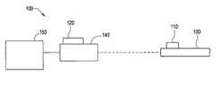
- FIG. 1illustrates an electromagnetic tracking system used in accordance with an embodiment of the present invention.
- FIG. 2shows a flow diagram for a method for configuring a tracking system used in accordance with an embodiment of the present invention.
- FIG. 3illustrates a dipole coil trio used in accordance with an embodiment of the present invention.
- FIG. 4illustrates a simplified diagram of a wired ISCA architecture, a wireless transmitter ISCA architecture, a wired single coil transmitter architecture, and a wireless single coil transmitter architecture, according to an embodiment of the present invention.
- FIG. 5illustrates a simplified diagram of an industry-standard coil architecture (ISCA), a second tracking system coil architecture, a third tracking system coil architecture, and a fourth tracking system coil architecture, according to an embodiment of the present invention.
- ISCAindustry-standard coil architecture
- FIG. 1illustrates an electromagnetic tracking system 100 used in accordance with an embodiment of the present invention.
- the tracking system 100includes a transmitter 110 , a receiver assembly 120 , an instrument 130 , an instrument guide 140 , and a tracker electronics 150 .
- the transmitter 110is positioned on the instrument 130 .
- the receiver assembly 120is located remotely from the instrument 130 and the transmitter 110 .
- the instrument guide 140is used to control the instrument 130 .
- the receiver assembly 120includes two receivers 122 , 124 .
- the receivers 122 , 124 of the receiver assembly 120may be receiver dipole coils or coil trios, for example.
- the receiver assembly 120may be attached to the instrument guide 140 .
- the instrument 130may be a surgical drill or other medical instrument, for example.
- the instrument guide 140may be a drill guide or other medical instrument guide, for example.
- the instrument 130 with instrument guide 140may be a tool that is indirectly controlled for applications wherein an operator's field of vision is obscured by an object.
- the transmitter 110may be a wired or wireless transmitter. In certain embodiments, the transmitter 110 is attached to the instrument 130 . Alternatively, the transmitter 110 may be integrated with the instrument 130 . Using the transmitter 110 and receiver assembly 120 , the position of the instrument 130 is tracked with respect to the instrument guide 140 or other reference point, for example.
- the system 100may also include one or more additional transmitters (not shown) for use in instrument 130 tracking.
- the additional transmitter(s)may be wired or wireless transmitter(s).
- a wireless second transmittermay be located on the instrument guide 140 or on the instrument 130 .
- a wired second transmittermay be located on the instrument guide 140 .
- the second transmittermay be wired to the tracker electronics 150 .
- a cablemay be run from the second transmitter to the tracker electronics 150 .
- the transmitter 110 and additional transmitter(s)may be tracked simultaneously from the receivers in the receiver assembly 120 .
- the transmitter 110may be an ISCA transmitter, such as an ISCA transmitter coil trio, for example.
- Software used with the tracker electronics 150may be configured to accommodate the transmitter 110 and/or another wired or wireless transmitter.
- the transmitter 110may draw power from the instrument 130 or may have a separate power source, for example.
- the transmitter 110may be tracked from each of the receivers in the receiver assembly 120 .
- certain embodimentsuse the transmitter 110 and the receiver assembly 120 to track the position of the instrument 130 with respect to the instrument guide 140 .
- the tracker electronics 150includes a Lucas 4650 processor, for example.
- the tracker electronics 150may be integrated with the receiver assembly 120 or may be a separate module, for example.
- the tracker electronics 150resides on a receiver assembly 120 board to perform a Sum of Products (SOP) and other calculations on signal data.
- SOPSum of Products
- the tracker electronics 150may include a large number of transmitter coil drivers (to accommodate a large number of transmitter coils used simultaneously, for example).
- the tracker electronics 150may also include a modular design permitting additional transmitter coil drivers to be added based on a coil architecture in use. Wireless transmitters have no direct, physical connection with the system 100 and may be added to the tracker electronics 150 with minimal effort.
- Waveforms for transmitter coil driversmay be stored in a memory, such as a random access memory (RAM) or hard disk drive, or may be generated on-the-fly by a software-controlled signal generator, such as a direct digital synthesizer (DDS), for example.
- a software-controlled signal generatorsuch as a direct digital synthesizer (DDS)
- Driver waveformsmay be changed for different coil architectures by changing data in the RAM or other memory storing the waveforms or by adjusting settings of the software-controlled generator.
- Driver waveformsmay be distinguished using sine waves of different frequencies, for example. A similar effect may be accomplished by using waveforms that are nonzero at different times or by using a spread-spectrum code division technique.
- the tracker electronics 150may include a large number of receiver coil preamplifier channels (to accommodate a large number of transmitter coils used simultaneously, for example). Alternatively, the tracker electronics 150 may include a modular design allowing additional receiver coil drivers to be added based on a coil architecture(s) in use. Wireless receiver coil preamplifer channels may be added as well.
- Signals emitted from receiver preamplifiersare transmitted to analog-to-digital converters (ADCs).
- ADCsdigitize the receiver preamplifier signals.
- Digital signals output from the ADCsare processed by software.
- the softwareis stored in RAM or other memory.
- the softwareextracts desired frequency components of the digital signals. The frequency components may be further processed to calculate the position and orientation of the receiver assembly or assemblies, for example.
- the softwareSince the software is stored in memory, algorithms, coil models, and processing schemes included in or generated by the software may be easily altered by modifying, reconfiguring, or replacing the software, for example.
- Softwaremay be modified to accommodate various coil architectures or system parameters.
- algorithms for multiple coil architecturesmay be loaded in memory. Multiple coil architecture algorithms and models, for example, allow multiple coil architectures to be run simultaneously. Rapid switching between architectures may also be facilitated using multiple configurations.
- the tracker electronics 150may register multiple coordinate systems for multiple architectures.
- an ISCA architecture and a single transmitter coil architecturemay be running simultaneously in the system 100 .
- a position and orientation of an ISCA receiverare determined with respect to an ISCA transmitter.
- a position and orientation of a single coil transmitterare determined with respect to a single transmitter coil receiver coil array (a spread-out coil array, for example).
- the receiver coil arraymay be used to track the ISCA transmitter coil trio.
- the receiver coil arraymay be used to determine position and orientation information (including roll, for example) of the ISCA transmitter with respect to the receiver coil array. Then, the position and orientation of the ISCA receiver with respect to the receiver coil array may be determined.
- an ISCA receivermay be tracked with respect to a transmitter coil array (a spread-out transmitter coil array, for example).
- Example coil architecturesinclude a wired ISCA architecture 10 , a wireless transmitter ISCA architecture 10 , a wired single coil transmitter architecture 30 , and a wireless single coil transmitter architecture 40 .
- a wired ISCA architecture 10three ISCA drivers drive a trio of transmitter coils. Four receiver coil trios each drive three receiver preamplifier channels.
- a wireless transmitter ISCA architecture 20an added wireless driver drives the three transmitter coils. Each of four receiver coil trios drives three receiver preamplifier channels in an array of twelve receiver preamplifier channels.
- an ISCA drivermay be used to drive the single transmitter coil.
- a twelve coil receiver assemblydrives twelve receiver preamplifier channels.
- a wireless transmitter architecture 40a wireless driver drives the single transmitter coil.
- a twelve coil receiver assemblydrives twelve receiver preamplifier channels.
- Mutual inductancemay be used in the electromagnetic tracking system to identify the positions of components in the system.
- Mutual inductancemay allow the system to be divided into two parts: coils and electronics. Determining mutual inductance involves a physical design of the coils and a geometrical relationship between the coils but may not use details of the electronics used to measure the mutual inductance. Additionally, mutual inductance does not depend on which coil receives an applied current.
- a system including one transmitter coil and one receiver coilforms a four-terminal two-port network.
- a varying current injected into one coilinduces a voltage in the other coil.
- L mis based on the geometry of the coils (closed circuits).
- L mis a ratio independent of applied current waveform or frequency.
- L mis a well-defined property that may be measured with reasonable precision.
- a positional relationship between the receiver coils in the receiver assembly 120is known.
- the receiver coilsreceive the signal transmitted by the wireless transmitter coil.
- the position and orientation of the wireless transmitter 110 relative to a reference coordinate systemmay then be determined using the mutual inductance between the receiver and transmitter coils and the positional relationship between the receiver coils.
- the resulting tracked position and orientation of the wireless transmitter 110 attached to the drill in relation to the receiver assembly 120 on the drill guidemay be used to help a user manipulate the drill inside the patient's body. Positioning information may help prevent injury to the patient and minimize unnecessary risk.
- the electromagnetic tracking system 100allows for the object being tracked to move freely without being limited by connections with a transmitter 110 or receiver 122 , 124 .
- passive transpondersmay employ a coil as a means of coupling with and receiving power from other devices.
- ratios between fieldsare measured, rather than absolute values. Precise ratios may be easier to obtain than precise absolute values.
- Five of six degrees of freedom for position and orientation measurementsmay be determined from ratios of received magnetic fields or mutual inductances, for example. Range (e.g., a distance from a receiver to a transmitter) may not be determined without a field strength or mutual inductance value.
- two receiver coil triossuch as ISCA receiver coil trios
- Position and orientation parametersaside from range, may be determined using magnetic field or mutual inductance ratio measurements from the six receivers in the two receiver coil trios. Additionally, a ratio of the ranges between the two receiver coil trios and the transmitter coil trio may be determined. Thus, a triangle is formed between the transmitter and receiver coil trios. The three angles of the triangle may be determined by ratio measurements. Additionally, a ratio of the two ranges is also determined. Using the three angles and the ratio of the two sides, the ratios of all three sides of the triangle may be determined. The side of the triangle that represents a distance between the two receiver coil trios may be determined based on construction of the receiver assembly 120 . Thus, by triangulation, the ranges between the two receivers 122 , 124 and the transmitter 110 may be determined (i.e., the remaining two sides of the triangle).
- FIG. 2shows a flow diagram for a method 200 for configuring a tracking system used in accordance with an embodiment of the present invention.
- componentssuch as the transmitter 110 and the receiver assembly 120 , are positioned.
- Coils, for example, in the transmitter 110 and/or the receiver assembly 120may be adjusted in a desired configuration.
- a trio of wireless transmitter coilsmay be positioned with respect to an array of wired receiver coil trios.
- a desired architectureis determined. For example, an operator selects an ISCA coil architecture for the system. Alternatively, the tracker electronics 150 or other processor may detect that an ISCA architecture is in use.
- a model and/or processing scheme for the current architectureare configured.
- software implementing an ISCA coil architecture and tracking algorithms for an ISCA architectureare configured in the tracker electronics 150 .
- driver waveform(s) for the architectureare loaded in the tracker electronics 150 .
- Software configured for the architecturemay also be loaded in the tracker electronics 150 .
- the appropriate software and driver waveformsare stored in RAM for use by the tracker electronics 150 .
- driver waveforms and softwareare generated on the fly by the tracker electronics 150 .
- the waveformsare used to drive the components in the architecture.
- driver waveformsare used to drive coils in the selected architecture.
- received signalsare analyzed.
- receiver coilsreceive signals or measurements, such as mutual inductance, magnetic fields, or current, from transmitter coils and transmit the received signals to the tracker electronics 150 for analysis.
- a position and orientation of a transmitter and/or receiverare determined. For example, signal ratios and/or triangulation between a transmitter and receivers may be used to determine position and orientation information.
- transmitter and/or receiver componentsmay be changed and a new architecture may be configured.
- components in a tracking systemmay be changed from an ISCA coil trio configuration to a single wireless transmitter coil architecture.
- multiple architecturesmay be supported simultaneously by the tracker electronics 150 .
- the tracker electronicsmay store and/or generate driver waveforms and operational information for both wired and wireless ISCA architectures.
- a wired transmitter coil trio and a wired receiver coil triomay be positioned in a wired ISCA configuration.
- the tracker electronics 150detect a wired ISCA architecture. Then, ISCA coil drivers are generated to drive the transmitter coils. Data is received at the receiver coils and processed by the tracker electronics 150 to determine position and orientation of the ISCA transmitter in relation to the ISCA receiver. Next, an operator adds a wireless transmitter. The operator selects a wireless ISCA mode of operation. The wireless coil drivers are loaded into RAM.
- the tracker electronics 150drives both the wired and wireless transmitter coils to determine position and orientation information.
- the tracker electronics 150supports multiple architectures simultaneously to improve flexibility and accuracy of system performance and position and orientation determination.
- certain embodiments of the present inventionprovide a system and method which permit a tracking system to operate with various coil architectures.
- the tracking systemmay operate with various coil architectures at different times and/or simultaneously.
- Certain embodimentsprovide a software-defined tracking system that accommodates a plurality of tracker coil architectures.
- Certain embodimentssimplify a tracking system for use in a multiple-application system, such as an image-guided surgery system. Certain embodiments allow existing tracking systems to be retrofitted for new tracker coil architectures without a loss of functionality. Software upgrades and replacement and/or additional coils may be used to modify current systems to accommodate multiple architectures at reduced cost without modification of tracker hardware. Thus, certain embodiments allow existing systems to be upgraded for new applications. Certain embodiments may open new retrofit markets for electromagnetic tracking systems.
- certain embodiments of the present inventionmay be used with a variety of tracking systems.
- coilsmay be replaced with other types of magnetic field detectors, such as flux gate magnetometers, superconducting quantum interference devices (SQUID), or magnetoresistance sensors.
- SQUIDsuperconducting quantum interference devices
- a software-configurable tracking systemmay be programmed to accommodate a variety of tracking architectures.
Landscapes
- Health & Medical Sciences (AREA)
- Life Sciences & Earth Sciences (AREA)
- Engineering & Computer Science (AREA)
- Surgery (AREA)
- Molecular Biology (AREA)
- Public Health (AREA)
- Veterinary Medicine (AREA)
- Biomedical Technology (AREA)
- Heart & Thoracic Surgery (AREA)
- Medical Informatics (AREA)
- General Health & Medical Sciences (AREA)
- Animal Behavior & Ethology (AREA)
- Pathology (AREA)
- Nuclear Medicine, Radiotherapy & Molecular Imaging (AREA)
- Human Computer Interaction (AREA)
- Physics & Mathematics (AREA)
- Biophysics (AREA)
- Oral & Maxillofacial Surgery (AREA)
- Robotics (AREA)
- Measurement Of Length, Angles, Or The Like Using Electric Or Magnetic Means (AREA)
- Magnetic Resonance Imaging Apparatus (AREA)
Abstract
Description
V=Lm(dI/dt) (2),
wherein Lmrepresents mutual inductance. Lmis based on the geometry of the coils (closed circuits). Lmis a ratio independent of applied current waveform or frequency. Thus, Lmis a well-defined property that may be measured with reasonable precision.
Claims (14)
Priority Applications (4)
| Application Number | Priority Date | Filing Date | Title |
|---|---|---|---|
| US10/670,054US8354837B2 (en) | 2003-09-24 | 2003-09-24 | System and method for electromagnetic tracking operable with multiple coil architectures |
| CA002481906ACA2481906A1 (en) | 2003-09-24 | 2004-09-16 | System and method for software configurable electromagnetic tracking |
| EP04255755AEP1519140A1 (en) | 2003-09-24 | 2004-09-22 | System and method for software configurable electromagnetic tracking |
| US11/289,849US7715898B2 (en) | 2003-09-24 | 2005-11-30 | System and method for employing multiple coil architectures simultaneously in one electromagnetic tracking system |
Applications Claiming Priority (1)
| Application Number | Priority Date | Filing Date | Title |
|---|---|---|---|
| US10/670,054US8354837B2 (en) | 2003-09-24 | 2003-09-24 | System and method for electromagnetic tracking operable with multiple coil architectures |
Related Child Applications (1)
| Application Number | Title | Priority Date | Filing Date |
|---|---|---|---|
| US11/289,849Continuation-In-PartUS7715898B2 (en) | 2003-09-24 | 2005-11-30 | System and method for employing multiple coil architectures simultaneously in one electromagnetic tracking system |
Publications (2)
| Publication Number | Publication Date |
|---|---|
| US20050065433A1 US20050065433A1 (en) | 2005-03-24 |
| US8354837B2true US8354837B2 (en) | 2013-01-15 |
Family
ID=34194816
Family Applications (2)
| Application Number | Title | Priority Date | Filing Date |
|---|---|---|---|
| US10/670,054Expired - Fee RelatedUS8354837B2 (en) | 2003-09-24 | 2003-09-24 | System and method for electromagnetic tracking operable with multiple coil architectures |
| US11/289,849Expired - Fee RelatedUS7715898B2 (en) | 2003-09-24 | 2005-11-30 | System and method for employing multiple coil architectures simultaneously in one electromagnetic tracking system |
Family Applications After (1)
| Application Number | Title | Priority Date | Filing Date |
|---|---|---|---|
| US11/289,849Expired - Fee RelatedUS7715898B2 (en) | 2003-09-24 | 2005-11-30 | System and method for employing multiple coil architectures simultaneously in one electromagnetic tracking system |
Country Status (3)
| Country | Link |
|---|---|
| US (2) | US8354837B2 (en) |
| EP (1) | EP1519140A1 (en) |
| CA (1) | CA2481906A1 (en) |
Cited By (9)
| Publication number | Priority date | Publication date | Assignee | Title |
|---|---|---|---|---|
| US9730764B2 (en) | 2015-10-02 | 2017-08-15 | Elucent Medical, Inc. | Signal tag detection components, devices, and systems |
| US9987097B2 (en) | 2015-10-02 | 2018-06-05 | Elucent Medical, Inc. | Signal tag detection components, devices, and systems |
| US10154799B2 (en) | 2016-08-12 | 2018-12-18 | Elucent Medical, Inc. | Surgical device guidance and monitoring devices, systems, and methods |
| US10188831B2 (en) | 2013-03-14 | 2019-01-29 | Angiodynamics, Inc. | Systems and methods for catheter tip placement using ECG |
| US10278779B1 (en) | 2018-06-05 | 2019-05-07 | Elucent Medical, Inc. | Exciter assemblies |
| US10285760B2 (en) | 2015-02-04 | 2019-05-14 | Queen's University At Kingston | Methods and apparatus for improved electromagnetic tracking and localization |
| US10620335B2 (en) | 2017-05-02 | 2020-04-14 | Ascension Technology Corporation | Rotating frequencies of transmitters |
| US11344382B2 (en) | 2014-01-24 | 2022-05-31 | Elucent Medical, Inc. | Systems and methods comprising localization agents |
| US11607150B2 (en) | 2014-04-08 | 2023-03-21 | Angiodynamics Va Llc | Medical device placement system and a method for its use |
Families Citing this family (54)
| Publication number | Priority date | Publication date | Assignee | Title |
|---|---|---|---|---|
| US7555333B2 (en)* | 2000-06-19 | 2009-06-30 | University Of Washington | Integrated optical scanning image acquisition and display |
| WO2004014219A2 (en)* | 2002-08-09 | 2004-02-19 | Kinamed, Inc. | Non-imaging tracking tools and method for hip replacement surgery |
| US7398116B2 (en) | 2003-08-11 | 2008-07-08 | Veran Medical Technologies, Inc. | Methods, apparatuses, and systems useful in conducting image guided interventions |
| US8150495B2 (en) | 2003-08-11 | 2012-04-03 | Veran Medical Technologies, Inc. | Bodily sealants and methods and apparatus for image-guided delivery of same |
| US7015859B2 (en)* | 2003-11-14 | 2006-03-21 | General Electric Company | Electromagnetic tracking system and method using a three-coil wireless transmitter |
| US7901348B2 (en)* | 2003-12-12 | 2011-03-08 | University Of Washington | Catheterscope 3D guidance and interface system |
| US7530948B2 (en)* | 2005-02-28 | 2009-05-12 | University Of Washington | Tethered capsule endoscope for Barrett's Esophagus screening |
| US20070066881A1 (en)* | 2005-09-13 | 2007-03-22 | Edwards Jerome R | Apparatus and method for image guided accuracy verification |
| EP1924198B1 (en) | 2005-09-13 | 2019-04-03 | Veran Medical Technologies, Inc. | Apparatus for image guided accuracy verification |
| WO2007067163A1 (en) | 2005-11-23 | 2007-06-14 | University Of Washington | Scanning beam with variable sequential framing using interrupted scanning resonance |
| US9561078B2 (en)* | 2006-03-03 | 2017-02-07 | University Of Washington | Multi-cladding optical fiber scanner |
| US9636188B2 (en)* | 2006-03-24 | 2017-05-02 | Stryker Corporation | System and method for 3-D tracking of surgical instrument in relation to patient body |
| US7471202B2 (en) | 2006-03-29 | 2008-12-30 | General Electric Co. | Conformal coil array for a medical tracking system |
| US7532997B2 (en) | 2006-04-17 | 2009-05-12 | General Electric Company | Electromagnetic tracking using a discretized numerical field model |
| US20080058629A1 (en)* | 2006-08-21 | 2008-03-06 | University Of Washington | Optical fiber scope with both non-resonant illumination and resonant collection/imaging for multiple modes of operation |
| US8197494B2 (en)* | 2006-09-08 | 2012-06-12 | Corpak Medsystems, Inc. | Medical device position guidance system with wireless connectivity between a noninvasive device and an invasive device |
| US20080118116A1 (en)* | 2006-11-20 | 2008-05-22 | General Electric Company | Systems and methods for tracking a surgical instrument and for conveying tracking information via a network |
| US20080132757A1 (en)* | 2006-12-01 | 2008-06-05 | General Electric Company | System and Method for Performing Minimally Invasive Surgery Using a Multi-Channel Catheter |
| US20080132834A1 (en)* | 2006-12-04 | 2008-06-05 | University Of Washington | Flexible endoscope tip bending mechanism using optical fibers as tension members |
| US20080139929A1 (en)* | 2006-12-06 | 2008-06-12 | General Electric Company | System and method for tracking an invasive surgical instrument while imaging a patient |
| US20080147173A1 (en)* | 2006-12-18 | 2008-06-19 | Medtronic Vascular, Inc. | Prosthesis Deployment Apparatus and Methods |
| US8473030B2 (en) | 2007-01-12 | 2013-06-25 | Medtronic Vascular, Inc. | Vessel position and configuration imaging apparatus and methods |
| US7573258B2 (en)* | 2007-01-18 | 2009-08-11 | General Electric Company | Coil arrangement for electromagnetic tracker method and system |
| US7508195B2 (en)* | 2007-01-18 | 2009-03-24 | General Electric Company | Anti-distortion electromagnetic sensor method and system |
| US7782046B2 (en)* | 2007-02-05 | 2010-08-24 | General Electric Company | Electromagnetic tracking method and system |
| US8249689B2 (en)* | 2007-02-23 | 2012-08-21 | General Electric Company | Coil arrangement for electromagnetic tracking method and system |
| US20080221388A1 (en)* | 2007-03-09 | 2008-09-11 | University Of Washington | Side viewing optical fiber endoscope |
| US7902817B2 (en)* | 2007-03-26 | 2011-03-08 | General Electric Company | Electromagnetic tracking method and system |
| US20080243030A1 (en)* | 2007-04-02 | 2008-10-02 | University Of Washington | Multifunction cannula tools |
| US8840566B2 (en) | 2007-04-02 | 2014-09-23 | University Of Washington | Catheter with imaging capability acts as guidewire for cannula tools |
| US7952718B2 (en)* | 2007-05-03 | 2011-05-31 | University Of Washington | High resolution optical coherence tomography based imaging for intraluminal and interstitial use implemented with a reduced form factor |
| US8024026B2 (en)* | 2007-05-31 | 2011-09-20 | General Electric Company | Dynamic reference method and system for use with surgical procedures |
| US7834621B2 (en)* | 2007-09-25 | 2010-11-16 | General Electric Company | Electromagnetic tracking employing scalar-magnetometer |
| US20090082665A1 (en)* | 2007-09-26 | 2009-03-26 | General Electric Company | System and method for tracking medical device |
| US8391952B2 (en)* | 2007-10-11 | 2013-03-05 | General Electric Company | Coil arrangement for an electromagnetic tracking system |
| US20090115406A1 (en)* | 2007-11-01 | 2009-05-07 | General Electric Company | System and method for minimizing mutual inductance coupling between coils in an electromagnetic tracking system |
| US20090137893A1 (en)* | 2007-11-27 | 2009-05-28 | University Of Washington | Adding imaging capability to distal tips of medical tools, catheters, and conduits |
| US8616974B2 (en)* | 2008-07-10 | 2013-12-31 | Sixense Entertainment, Inc. | Passive and active video game controllers with magnetic position sensing |
| DE102009010592B4 (en)* | 2009-02-25 | 2014-09-04 | Carl Zeiss Meditec Ag | Method and device for recording and evaluating digital image data with a surgical microscope |
| US20100305427A1 (en)* | 2009-06-01 | 2010-12-02 | General Electric Company | Long-range planar sensor array for use in a surgical navigation system |
| US8475407B2 (en)* | 2010-03-25 | 2013-07-02 | Medtronic, Inc. | Method and apparatus for guiding an external needle to an implantable device |
| US9216257B2 (en)* | 2010-03-25 | 2015-12-22 | Medtronic, Inc. | Method and apparatus for guiding an external needle to an implantable device |
| US8483802B2 (en)* | 2010-03-25 | 2013-07-09 | Medtronic, Inc. | Method and apparatus for guiding an external needle to an implantable device |
| US9339601B2 (en)* | 2010-03-25 | 2016-05-17 | Medtronic, Inc. | Method and apparatus for guiding an external needle to an implantable device |
| JP2013530028A (en) | 2010-05-04 | 2013-07-25 | パスファインダー セラピューティクス,インコーポレイテッド | System and method for abdominal surface matching using pseudo features |
| EP3659490B1 (en) | 2010-08-20 | 2025-10-01 | Veran Medical Technologies, Inc. | Apparatus and method for four dimensional soft tissue navigation |
| EP2816966B1 (en) | 2012-02-22 | 2023-10-25 | Veran Medical Technologies, Inc. | Steerable surgical catheter comprising a biopsy device at the distal end portion thereof |
| US9480415B2 (en) | 2013-04-26 | 2016-11-01 | Medtronic Navigation, Inc. | Electromagnetic coil apparatuses for surgical navigation and corresponding methods |
| AU2015201655B2 (en) | 2014-04-07 | 2020-01-02 | Xcalibur Mph Switzerland Sa | Electromagnetic receiver tracking and real-time calibration system and method |
| US20150305650A1 (en) | 2014-04-23 | 2015-10-29 | Mark Hunter | Apparatuses and methods for endobronchial navigation to and confirmation of the location of a target tissue and percutaneous interception of the target tissue |
| US20150305612A1 (en) | 2014-04-23 | 2015-10-29 | Mark Hunter | Apparatuses and methods for registering a real-time image feed from an imaging device to a steerable catheter |
| US10136968B2 (en)* | 2014-12-24 | 2018-11-27 | Isethco Llc | Disposable surgical intervention guides, methods, and kits |
| US9962234B2 (en) | 2014-12-24 | 2018-05-08 | Isethco Llc | Disposable surgical intervention guides, methods, and kits |
| US11096605B2 (en) | 2015-03-31 | 2021-08-24 | Medtronic Navigation, Inc. | Modular coil assembly |
Citations (68)
| Publication number | Priority date | Publication date | Assignee | Title |
|---|---|---|---|---|
| US3868565A (en) | 1973-07-30 | 1975-02-25 | Jack Kuipers | Object tracking and orientation determination means, system and process |
| US3983474A (en) | 1975-02-21 | 1976-09-28 | Polhemus Navigation Sciences, Inc. | Tracking and determining orientation of object using coordinate transformation means, system and process |
| US4054881A (en) | 1976-04-26 | 1977-10-18 | The Austin Company | Remote object position locater |
| US4176662A (en) | 1977-06-17 | 1979-12-04 | The United States Of America As Represented By The Administrator Of The National Aeronautics And Space Administration | Apparatus for endoscopic examination |
| US4613866A (en) | 1983-05-13 | 1986-09-23 | Mcdonnell Douglas Corporation | Three dimensional digitizer with electromagnetic coupling |
| US4618822A (en) | 1984-04-18 | 1986-10-21 | Position Orientation Systems, Ltd. | Displacement sensing device utilizing adjustable tuned circuit |
| US4622644A (en) | 1984-05-10 | 1986-11-11 | Position Orientation Systems, Ltd. | Magnetic position and orientation measurement system |
| US4642786A (en) | 1984-05-25 | 1987-02-10 | Position Orientation Systems, Ltd. | Method and apparatus for position and orientation measurement using a magnetic field and retransmission |
| US4710708A (en) | 1981-04-27 | 1987-12-01 | Develco | Method and apparatus employing received independent magnetic field components of a transmitted alternating magnetic field for determining location |
| US4737794A (en) | 1985-12-09 | 1988-04-12 | Mcdonnell Douglas Corporation | Method and apparatus for determining remote object orientation and position |
| US4742356A (en) | 1985-12-09 | 1988-05-03 | Mcdonnell Douglas Corporation | Method and apparatus for determining remote object orientation and position |
| JPH01303140A (en) | 1988-06-01 | 1989-12-07 | Hitachi Ltd | Nuclear magnetic resonance diagnostic equipment |
| US5099845A (en) | 1989-05-24 | 1992-03-31 | Micronix Pty Ltd. | Medical instrument location means |
| US5211165A (en) | 1991-09-03 | 1993-05-18 | General Electric Company | Tracking system to follow the position and orientation of a device with radiofrequency field gradients |
| EP0543551A1 (en) | 1991-11-18 | 1993-05-26 | General Electric Company | Inductively coupled RF tracking system for use in invasive imaging of a living body |
| US5251635A (en) | 1991-09-03 | 1993-10-12 | General Electric Company | Stereoscopic X-ray fluoroscopy system using radiofrequency fields |
| US5255680A (en) | 1991-09-03 | 1993-10-26 | General Electric Company | Automatic gantry positioning for imaging systems |
| US5265610A (en) | 1991-09-03 | 1993-11-30 | General Electric Company | Multi-planar X-ray fluoroscopy system using radiofrequency fields |
| US5307072A (en) | 1992-07-09 | 1994-04-26 | Polhemus Incorporated | Non-concentricity compensation in position and orientation measurement systems |
| US5377678A (en) | 1991-09-03 | 1995-01-03 | General Electric Company | Tracking system to follow the position and orientation of a device with radiofrequency fields |
| US5425382A (en) | 1993-09-14 | 1995-06-20 | University Of Washington | Apparatus and method for locating a medical tube in the body of a patient |
| US5425367A (en) | 1991-09-04 | 1995-06-20 | Navion Biomedical Corporation | Catheter depth, position and orientation location system |
| US5437277A (en) | 1991-11-18 | 1995-08-01 | General Electric Company | Inductively coupled RF tracking system for use in invasive imaging of a living body |
| US5443066A (en) | 1991-11-18 | 1995-08-22 | General Electric Company | Invasive system employing a radiofrequency tracking system |
| US5517195A (en) | 1994-09-14 | 1996-05-14 | Sensormatic Electronics Corporation | Dual frequency EAS tag with deactivation coil |
| US5558091A (en) | 1993-10-06 | 1996-09-24 | Biosense, Inc. | Magnetic determination of position and orientation |
| US5570021A (en) | 1995-10-10 | 1996-10-29 | General Electric Company | MR gradient set coil support assembly |
| JPH09507A (en) | 1995-06-22 | 1997-01-07 | Ge Yokogawa Medical Syst Ltd | Coil mechanism of magnetic resonance photographing device |
| US5592939A (en) | 1995-06-14 | 1997-01-14 | Martinelli; Michael A. | Method and system for navigating a catheter probe |
| US5676673A (en) | 1994-09-15 | 1997-10-14 | Visualization Technology, Inc. | Position tracking and imaging system with error detection for use in medical applications |
| US5747996A (en) | 1994-03-09 | 1998-05-05 | U.S. Philips Corporation | Device for determining the spatial position of a sensor element which is displacement relative to a reference element |
| US5829444A (en) | 1994-09-15 | 1998-11-03 | Visualization Technology, Inc. | Position tracking and imaging system for use in medical applications |
| US5876325A (en) | 1993-11-02 | 1999-03-02 | Olympus Optical Co., Ltd. | Surgical manipulation system |
| US6039701A (en) | 1996-09-05 | 2000-03-21 | Ob Inovations, Inc. | Method and apparatus for monitoring cervical diameter |
| US6052610A (en) | 1998-01-09 | 2000-04-18 | International Business Machines Corporation | Magnetic catheter tracker and method therefor |
| US6059718A (en) | 1993-10-18 | 2000-05-09 | Olympus Optical Co., Ltd. | Endoscope form detecting apparatus in which coil is fixedly mounted by insulating member so that form is not deformed within endoscope |
| US6073043A (en) | 1997-12-22 | 2000-06-06 | Cormedica Corporation | Measuring position and orientation using magnetic fields |
| US6129668A (en) | 1997-05-08 | 2000-10-10 | Lucent Medical Systems, Inc. | System and method to determine the location and orientation of an indwelling medical device |
| US6129667A (en) | 1998-02-02 | 2000-10-10 | General Electric Company | Luminal diagnostics employing spectral analysis |
| US6177792B1 (en) | 1996-03-26 | 2001-01-23 | Bisense, Inc. | Mutual induction correction for radiator coils of an objects tracking system |
| US6188355B1 (en) | 1997-12-12 | 2001-02-13 | Super Dimension Ltd. | Wireless six-degree-of-freedom locator |
| US6201987B1 (en) | 1998-05-26 | 2001-03-13 | General Electric Company | Error compensation for device tracking systems employing electromagnetic fields |
| US6226547B1 (en) | 1997-11-15 | 2001-05-01 | Roke Manor Research Limited | Catheter tracking system |
| US6230038B1 (en) | 1999-02-01 | 2001-05-08 | International Business Machines Corporation | Imaging of internal structures of living bodies by sensing implanted magnetic devices |
| US6233476B1 (en) | 1999-05-18 | 2001-05-15 | Mediguide Ltd. | Medical positioning system |
| US6246898B1 (en) | 1995-03-28 | 2001-06-12 | Sonometrics Corporation | Method for carrying out a medical procedure using a three-dimensional tracking and imaging system |
| US6259372B1 (en) | 1999-01-22 | 2001-07-10 | Eaton Corporation | Self-powered wireless transducer |
| US6289233B1 (en) | 1998-11-25 | 2001-09-11 | General Electric Company | High speed tracking of interventional devices using an MRI system |
| US20020008516A1 (en) | 2000-07-06 | 2002-01-24 | Siemens Aktiengesellschaft | Magnetic resonance apparatus having a mechanically damped gradient coil system |
| EP1193507A2 (en) | 2000-10-02 | 2002-04-03 | General Electric Company | Low noise MRI scanner |
| US6369564B1 (en) | 1999-11-01 | 2002-04-09 | Polhemus, Inc. | Electromagnetic position and orientation tracking system with distortion compensation employing wireless sensors |
| US6374131B1 (en) | 1999-07-28 | 2002-04-16 | Shimadzu Corporation | Biomagnetism measuring method and apparatus |
| US6374134B1 (en) | 1992-08-14 | 2002-04-16 | British Telecommunications Public Limited Company | Simultaneous display during surgical navigation |
| US6427079B1 (en) | 1999-08-09 | 2002-07-30 | Cormedica Corporation | Position and orientation measuring with magnetic fields |
| US6456074B1 (en) | 2000-01-28 | 2002-09-24 | Intermagnetics General Corporation | Quiet gradient coil |
| US6459882B1 (en) | 1995-05-18 | 2002-10-01 | Aura Communications, Inc. | Inductive communication system and method |
| US6463039B1 (en) | 1998-04-24 | 2002-10-08 | Intelligent Ideation, Inc. | Method and apparatus for full duplex sideband communication |
| US6472975B1 (en) | 1994-06-20 | 2002-10-29 | Avid Marketing, Inc. | Electronic identification system with improved sensitivity |
| US6490475B1 (en) | 2000-04-28 | 2002-12-03 | Ge Medical Systems Global Technology Company, Llc | Fluoroscopic tracking and visualization system |
| US6492816B1 (en) | 1999-10-07 | 2002-12-10 | Peter John Feenan | Acoustic liner for mri gradient coils |
| US20030184285A1 (en)* | 2002-03-27 | 2003-10-02 | Visualization Technology | Magnetic tracking system |
| US6636757B1 (en) | 2001-06-04 | 2003-10-21 | Surgical Navigation Technologies, Inc. | Method and apparatus for electromagnetic navigation of a surgical probe near a metal object |
| EP1493384A1 (en) | 2003-07-01 | 2005-01-05 | GE Medical Systems Global Technology Company LLC | Electromagnetic tracking system and method using a single-coil transmitter |
| US20050012597A1 (en) | 2003-07-02 | 2005-01-20 | Anderson Peter Traneus | Wireless electromagnetic tracking system using a nonlinear passive transponder |
| US20050024043A1 (en)* | 2003-07-31 | 2005-02-03 | Assaf Govari | Detection of metal disturbance in a magnetic tracking system |
| US6856826B2 (en) | 2000-04-28 | 2005-02-15 | Ge Medical Systems Global Technology Company, Llc | Fluoroscopic tracking and visualization system |
| US6856827B2 (en) | 2000-04-28 | 2005-02-15 | Ge Medical Systems Global Technology Company, Llc | Fluoroscopic tracking and visualization system |
| US20050059883A1 (en)* | 2003-09-12 | 2005-03-17 | Peterson Thomas Herbert | System and method for determining the position of a flexible instrument used in a tracking system |
- 2003
- 2003-09-24USUS10/670,054patent/US8354837B2/ennot_activeExpired - Fee Related
- 2004
- 2004-09-16CACA002481906Apatent/CA2481906A1/ennot_activeAbandoned
- 2004-09-22EPEP04255755Apatent/EP1519140A1/ennot_activeCeased
- 2005
- 2005-11-30USUS11/289,849patent/US7715898B2/ennot_activeExpired - Fee Related
Patent Citations (78)
| Publication number | Priority date | Publication date | Assignee | Title |
|---|---|---|---|---|
| US3868565A (en) | 1973-07-30 | 1975-02-25 | Jack Kuipers | Object tracking and orientation determination means, system and process |
| US3983474A (en) | 1975-02-21 | 1976-09-28 | Polhemus Navigation Sciences, Inc. | Tracking and determining orientation of object using coordinate transformation means, system and process |
| US4054881A (en) | 1976-04-26 | 1977-10-18 | The Austin Company | Remote object position locater |
| US4176662A (en) | 1977-06-17 | 1979-12-04 | The United States Of America As Represented By The Administrator Of The National Aeronautics And Space Administration | Apparatus for endoscopic examination |
| US4710708A (en) | 1981-04-27 | 1987-12-01 | Develco | Method and apparatus employing received independent magnetic field components of a transmitted alternating magnetic field for determining location |
| US4613866A (en) | 1983-05-13 | 1986-09-23 | Mcdonnell Douglas Corporation | Three dimensional digitizer with electromagnetic coupling |
| US4618822A (en) | 1984-04-18 | 1986-10-21 | Position Orientation Systems, Ltd. | Displacement sensing device utilizing adjustable tuned circuit |
| US4622644A (en) | 1984-05-10 | 1986-11-11 | Position Orientation Systems, Ltd. | Magnetic position and orientation measurement system |
| US4642786A (en) | 1984-05-25 | 1987-02-10 | Position Orientation Systems, Ltd. | Method and apparatus for position and orientation measurement using a magnetic field and retransmission |
| US4737794A (en) | 1985-12-09 | 1988-04-12 | Mcdonnell Douglas Corporation | Method and apparatus for determining remote object orientation and position |
| US4742356A (en) | 1985-12-09 | 1988-05-03 | Mcdonnell Douglas Corporation | Method and apparatus for determining remote object orientation and position |
| JPH01303140A (en) | 1988-06-01 | 1989-12-07 | Hitachi Ltd | Nuclear magnetic resonance diagnostic equipment |
| US5099845A (en) | 1989-05-24 | 1992-03-31 | Micronix Pty Ltd. | Medical instrument location means |
| US5211165A (en) | 1991-09-03 | 1993-05-18 | General Electric Company | Tracking system to follow the position and orientation of a device with radiofrequency field gradients |
| US5377678A (en) | 1991-09-03 | 1995-01-03 | General Electric Company | Tracking system to follow the position and orientation of a device with radiofrequency fields |
| US5251635A (en) | 1991-09-03 | 1993-10-12 | General Electric Company | Stereoscopic X-ray fluoroscopy system using radiofrequency fields |
| US5255680A (en) | 1991-09-03 | 1993-10-26 | General Electric Company | Automatic gantry positioning for imaging systems |
| US5265610A (en) | 1991-09-03 | 1993-11-30 | General Electric Company | Multi-planar X-ray fluoroscopy system using radiofrequency fields |
| US5425367A (en) | 1991-09-04 | 1995-06-20 | Navion Biomedical Corporation | Catheter depth, position and orientation location system |
| US5437277A (en) | 1991-11-18 | 1995-08-01 | General Electric Company | Inductively coupled RF tracking system for use in invasive imaging of a living body |
| US5443066A (en) | 1991-11-18 | 1995-08-22 | General Electric Company | Invasive system employing a radiofrequency tracking system |
| US5445150A (en) | 1991-11-18 | 1995-08-29 | General Electric Company | Invasive system employing a radiofrequency tracking system |
| EP0543551A1 (en) | 1991-11-18 | 1993-05-26 | General Electric Company | Inductively coupled RF tracking system for use in invasive imaging of a living body |
| US5307072A (en) | 1992-07-09 | 1994-04-26 | Polhemus Incorporated | Non-concentricity compensation in position and orientation measurement systems |
| US6374134B1 (en) | 1992-08-14 | 2002-04-16 | British Telecommunications Public Limited Company | Simultaneous display during surgical navigation |
| US5622169A (en) | 1993-09-14 | 1997-04-22 | University Of Washington | Apparatus and method for locating a medical tube in the body of a patient |
| US5425382A (en) | 1993-09-14 | 1995-06-20 | University Of Washington | Apparatus and method for locating a medical tube in the body of a patient |
| US5558091A (en) | 1993-10-06 | 1996-09-24 | Biosense, Inc. | Magnetic determination of position and orientation |
| US6059718A (en) | 1993-10-18 | 2000-05-09 | Olympus Optical Co., Ltd. | Endoscope form detecting apparatus in which coil is fixedly mounted by insulating member so that form is not deformed within endoscope |
| US5876325A (en) | 1993-11-02 | 1999-03-02 | Olympus Optical Co., Ltd. | Surgical manipulation system |
| US5747996A (en) | 1994-03-09 | 1998-05-05 | U.S. Philips Corporation | Device for determining the spatial position of a sensor element which is displacement relative to a reference element |
| US6472975B1 (en) | 1994-06-20 | 2002-10-29 | Avid Marketing, Inc. | Electronic identification system with improved sensitivity |
| US5517195A (en) | 1994-09-14 | 1996-05-14 | Sensormatic Electronics Corporation | Dual frequency EAS tag with deactivation coil |
| US5829444A (en) | 1994-09-15 | 1998-11-03 | Visualization Technology, Inc. | Position tracking and imaging system for use in medical applications |
| US5873822A (en) | 1994-09-15 | 1999-02-23 | Visualization Technology, Inc. | Automatic registration system for use with position tracking and imaging system for use in medical applications |
| US6341231B1 (en) | 1994-09-15 | 2002-01-22 | Visualization Technology, Inc. | Position tracking and imaging system for use in medical applications |
| US6175756B1 (en) | 1994-09-15 | 2001-01-16 | Visualization Technology Inc. | Position tracking and imaging system for use in medical applications |
| US5803089A (en) | 1994-09-15 | 1998-09-08 | Visualization Technology, Inc. | Position tracking and imaging system for use in medical applications |
| US5676673A (en) | 1994-09-15 | 1997-10-14 | Visualization Technology, Inc. | Position tracking and imaging system with error detection for use in medical applications |
| US5967980A (en) | 1994-09-15 | 1999-10-19 | Visualization Technology, Inc. | Position tracking and imaging system for use in medical applications |
| US6445943B1 (en) | 1994-09-15 | 2002-09-03 | Visualization Technology, Inc. | Position tracking and imaging system for use in medical applications |
| US6246898B1 (en) | 1995-03-28 | 2001-06-12 | Sonometrics Corporation | Method for carrying out a medical procedure using a three-dimensional tracking and imaging system |
| US6459882B1 (en) | 1995-05-18 | 2002-10-01 | Aura Communications, Inc. | Inductive communication system and method |
| US5592939A (en) | 1995-06-14 | 1997-01-14 | Martinelli; Michael A. | Method and system for navigating a catheter probe |
| JPH09507A (en) | 1995-06-22 | 1997-01-07 | Ge Yokogawa Medical Syst Ltd | Coil mechanism of magnetic resonance photographing device |
| US5570021A (en) | 1995-10-10 | 1996-10-29 | General Electric Company | MR gradient set coil support assembly |
| US6177792B1 (en) | 1996-03-26 | 2001-01-23 | Bisense, Inc. | Mutual induction correction for radiator coils of an objects tracking system |
| US6039701A (en) | 1996-09-05 | 2000-03-21 | Ob Inovations, Inc. | Method and apparatus for monitoring cervical diameter |
| US6129668A (en) | 1997-05-08 | 2000-10-10 | Lucent Medical Systems, Inc. | System and method to determine the location and orientation of an indwelling medical device |
| US6226547B1 (en) | 1997-11-15 | 2001-05-01 | Roke Manor Research Limited | Catheter tracking system |
| US6188355B1 (en) | 1997-12-12 | 2001-02-13 | Super Dimension Ltd. | Wireless six-degree-of-freedom locator |
| US6073043A (en) | 1997-12-22 | 2000-06-06 | Cormedica Corporation | Measuring position and orientation using magnetic fields |
| US6052610A (en) | 1998-01-09 | 2000-04-18 | International Business Machines Corporation | Magnetic catheter tracker and method therefor |
| US6129667A (en) | 1998-02-02 | 2000-10-10 | General Electric Company | Luminal diagnostics employing spectral analysis |
| US6463039B1 (en) | 1998-04-24 | 2002-10-08 | Intelligent Ideation, Inc. | Method and apparatus for full duplex sideband communication |
| US6201987B1 (en) | 1998-05-26 | 2001-03-13 | General Electric Company | Error compensation for device tracking systems employing electromagnetic fields |
| US6289233B1 (en) | 1998-11-25 | 2001-09-11 | General Electric Company | High speed tracking of interventional devices using an MRI system |
| US6259372B1 (en) | 1999-01-22 | 2001-07-10 | Eaton Corporation | Self-powered wireless transducer |
| US6230038B1 (en) | 1999-02-01 | 2001-05-08 | International Business Machines Corporation | Imaging of internal structures of living bodies by sensing implanted magnetic devices |
| US6233476B1 (en) | 1999-05-18 | 2001-05-15 | Mediguide Ltd. | Medical positioning system |
| US6374131B1 (en) | 1999-07-28 | 2002-04-16 | Shimadzu Corporation | Biomagnetism measuring method and apparatus |
| US6427079B1 (en) | 1999-08-09 | 2002-07-30 | Cormedica Corporation | Position and orientation measuring with magnetic fields |
| US6492816B1 (en) | 1999-10-07 | 2002-12-10 | Peter John Feenan | Acoustic liner for mri gradient coils |
| US6369564B1 (en) | 1999-11-01 | 2002-04-09 | Polhemus, Inc. | Electromagnetic position and orientation tracking system with distortion compensation employing wireless sensors |
| US6456074B1 (en) | 2000-01-28 | 2002-09-24 | Intermagnetics General Corporation | Quiet gradient coil |
| US6856827B2 (en) | 2000-04-28 | 2005-02-15 | Ge Medical Systems Global Technology Company, Llc | Fluoroscopic tracking and visualization system |
| US6856826B2 (en) | 2000-04-28 | 2005-02-15 | Ge Medical Systems Global Technology Company, Llc | Fluoroscopic tracking and visualization system |
| US6490475B1 (en) | 2000-04-28 | 2002-12-03 | Ge Medical Systems Global Technology Company, Llc | Fluoroscopic tracking and visualization system |
| US20020008516A1 (en) | 2000-07-06 | 2002-01-24 | Siemens Aktiengesellschaft | Magnetic resonance apparatus having a mechanically damped gradient coil system |
| EP1193507A2 (en) | 2000-10-02 | 2002-04-03 | General Electric Company | Low noise MRI scanner |
| US6636757B1 (en) | 2001-06-04 | 2003-10-21 | Surgical Navigation Technologies, Inc. | Method and apparatus for electromagnetic navigation of a surgical probe near a metal object |
| US6774624B2 (en) | 2002-03-27 | 2004-08-10 | Ge Medical Systems Global Technology Company, Llc | Magnetic tracking system |
| US20030184285A1 (en)* | 2002-03-27 | 2003-10-02 | Visualization Technology | Magnetic tracking system |
| EP1493384A1 (en) | 2003-07-01 | 2005-01-05 | GE Medical Systems Global Technology Company LLC | Electromagnetic tracking system and method using a single-coil transmitter |
| US20050003757A1 (en)* | 2003-07-01 | 2005-01-06 | Anderson Peter Traneus | Electromagnetic tracking system and method using a single-coil transmitter |
| US20050012597A1 (en) | 2003-07-02 | 2005-01-20 | Anderson Peter Traneus | Wireless electromagnetic tracking system using a nonlinear passive transponder |
| US20050024043A1 (en)* | 2003-07-31 | 2005-02-03 | Assaf Govari | Detection of metal disturbance in a magnetic tracking system |
| US20050059883A1 (en)* | 2003-09-12 | 2005-03-17 | Peterson Thomas Herbert | System and method for determining the position of a flexible instrument used in a tracking system |
Non-Patent Citations (7)
| Title |
|---|
| .Sep. 14 and 17, 2007 Communication regarding counterpart EP App. No. 04255755.3-1524. |
| •Sep. 14 and 17, 2007 Communication regarding counterpart EP App. No. 04255755.3-1524. |
| Jan. 19, 2005 Communication regarding counterpart EP App. No. 04255755.3-1524. |
| Jul. 7, 2006 Communication regarding counterpart EP App. No. 04255755.3-1524. |
| Nov. 17, 2005 Communication regarding counterpart EP App. No. 04255755.3-1524. |
| Peter T. Anderson, A Source of Accurately Calculable Quasi-Static Magnetic Fields, Oct. 2001. |
| Tom Ahlkvist Scharfeld, An Analysis of the Fundamental Constraints on Low Cost Passive Radio-Frequency Identification System Design, Aug. 2001. |
Cited By (21)
| Publication number | Priority date | Publication date | Assignee | Title |
|---|---|---|---|---|
| US10188831B2 (en) | 2013-03-14 | 2019-01-29 | Angiodynamics, Inc. | Systems and methods for catheter tip placement using ECG |
| US11344382B2 (en) | 2014-01-24 | 2022-05-31 | Elucent Medical, Inc. | Systems and methods comprising localization agents |
| US11607150B2 (en) | 2014-04-08 | 2023-03-21 | Angiodynamics Va Llc | Medical device placement system and a method for its use |
| US10285760B2 (en) | 2015-02-04 | 2019-05-14 | Queen's University At Kingston | Methods and apparatus for improved electromagnetic tracking and localization |
| US10245119B2 (en) | 2015-10-02 | 2019-04-02 | Elucent Medical, Inc. | Signal tag detection components, devices, and systems |
| US11786333B2 (en) | 2015-10-02 | 2023-10-17 | Elucent Medical, Inc. | Signal tag detection components, devices, and systems |
| US12245902B2 (en) | 2015-10-02 | 2025-03-11 | Elucent Medical, Inc. | Signal tag detection components, devices, and systems |
| US10245118B2 (en) | 2015-10-02 | 2019-04-02 | Elucent Medical, Inc. | Signal tag detection components, devices, and systems |
| US9730764B2 (en) | 2015-10-02 | 2017-08-15 | Elucent Medical, Inc. | Signal tag detection components, devices, and systems |
| US10751145B2 (en) | 2015-10-02 | 2020-08-25 | Elucent Medical, Inc. | Signal tag detection components, devices, and systems |
| US11135034B2 (en) | 2015-10-02 | 2021-10-05 | Elucent Medical, Inc. | Signal tag detection components, devices, and systems |
| US9987097B2 (en) | 2015-10-02 | 2018-06-05 | Elucent Medical, Inc. | Signal tag detection components, devices, and systems |
| US11298044B2 (en) | 2016-08-12 | 2022-04-12 | Elucent Medical, Inc. | Surgical device guidance and monitoring devices, systems, and methods |
| US10154799B2 (en) | 2016-08-12 | 2018-12-18 | Elucent Medical, Inc. | Surgical device guidance and monitoring devices, systems, and methods |
| US12357192B2 (en) | 2016-08-12 | 2025-07-15 | Elucent Medical, Inc. | Surgical device guidance and monitoring devices, systems, and methods |
| US10620335B2 (en) | 2017-05-02 | 2020-04-14 | Ascension Technology Corporation | Rotating frequencies of transmitters |
| US11540885B2 (en) | 2018-06-05 | 2023-01-03 | Elucent Medical, Inc. | Orthogonally isolated exciter with field steering |
| US11185375B2 (en) | 2018-06-05 | 2021-11-30 | Elucent Medical, Inc. | Exciter assemblies |
| US11666391B2 (en) | 2018-06-05 | 2023-06-06 | Elucent Medical, Inc. | Exciter assemblies |
| US12186029B2 (en) | 2018-06-05 | 2025-01-07 | Elucent Medical, Inc. | Exciter assemblies |
| US10278779B1 (en) | 2018-06-05 | 2019-05-07 | Elucent Medical, Inc. | Exciter assemblies |
Also Published As
| Publication number | Publication date |
|---|---|
| US20060106292A1 (en) | 2006-05-18 |
| US7715898B2 (en) | 2010-05-11 |
| CA2481906A1 (en) | 2005-03-24 |
| US20050065433A1 (en) | 2005-03-24 |
| EP1519140A1 (en) | 2005-03-30 |
Similar Documents
| Publication | Publication Date | Title |
|---|---|---|
| US8354837B2 (en) | System and method for electromagnetic tracking operable with multiple coil architectures | |
| JP5581042B2 (en) | Object tracking system | |
| US7015859B2 (en) | Electromagnetic tracking system and method using a three-coil wireless transmitter | |
| JP5160087B2 (en) | Magnetic sensor array | |
| US8131342B2 (en) | Method and system for field mapping using integral methodology | |
| US8391952B2 (en) | Coil arrangement for an electromagnetic tracking system | |
| US20060025668A1 (en) | Operating table with embedded tracking technology | |
| JP5420148B2 (en) | How to locate the magnetic source | |
| JP4884960B2 (en) | Apparatus and method for registering a patient's bone using a computer-assisted orthopedic surgery system | |
| US8249689B2 (en) | Coil arrangement for electromagnetic tracking method and system | |
| US20100249571A1 (en) | Surgical navigation system with wireless magnetoresistance tracking sensors | |
| US20060267759A1 (en) | Position and Orientation Tracking of Transponder | |
| US8358128B2 (en) | Surgical navigation system with magnetoresistance sensors | |
| US7573258B2 (en) | Coil arrangement for electromagnetic tracker method and system | |
| US20090115406A1 (en) | System and method for minimizing mutual inductance coupling between coils in an electromagnetic tracking system | |
| JP2007519432A (en) | System and method for distortion reduction in an electromagnetic tracker | |
| US20090082665A1 (en) | System and method for tracking medical device | |
| US7471202B2 (en) | Conformal coil array for a medical tracking system | |
| GB2331807A (en) | Catheter tracking system | |
| JP2007181694A (en) | System and method for registering bone of patient with computer assisted orthopaedic surgery system | |
| US20050062469A1 (en) | System and method for hemisphere disambiguation in electromagnetic tracking systems | |
| US7640121B2 (en) | System and method for disambiguating the phase of a field received from a transmitter in an electromagnetic tracking system | |
| US9008756B2 (en) | Mapping system and method for mapping a target containing tissue | |
| US20090085559A1 (en) | System and method for minimizing electromagnetic field distortion in an electromagnetic tracking system | |
| CA2220250C (en) | Magnetic location system with adaptive feedback control |
Legal Events
| Date | Code | Title | Description |
|---|---|---|---|
| AS | Assignment | Owner name:GE MEDICAL SYSTEMS GLOBAL TECHNOLOGY COMPANY, LLC, Free format text:ASSIGNMENT OF ASSIGNORS INTEREST;ASSIGNOR:ANDERSON, PETER T.;REEL/FRAME:014553/0067 Effective date:20030918 | |
| AS | Assignment | Owner name:G.E. MEDICAL SYSTEMS GLOBAL TECHNOLOGY CO., LLC, W Free format text:ASSIGNMENT OF ASSIGNORS INTEREST;ASSIGNOR:ANDERSON, PETER TRANEUS;REEL/FRAME:015096/0919 Effective date:20040818 | |
| FEPP | Fee payment procedure | Free format text:PAYOR NUMBER ASSIGNED (ORIGINAL EVENT CODE: ASPN); ENTITY STATUS OF PATENT OWNER: LARGE ENTITY | |
| STCF | Information on status: patent grant | Free format text:PATENTED CASE | |
| FPAY | Fee payment | Year of fee payment:4 | |
| AS | Assignment | Owner name:STRYKER EUROPEAN HOLDINGS I, LLC, MICHIGAN Free format text:ASSIGNMENT OF ASSIGNORS INTEREST;ASSIGNOR:GENERAL ELECTRIC COMPANY;REEL/FRAME:046020/0621 Effective date:20171206 | |
| MAFP | Maintenance fee payment | Free format text:PAYMENT OF MAINTENANCE FEE, 8TH YEAR, LARGE ENTITY (ORIGINAL EVENT CODE: M1552); ENTITY STATUS OF PATENT OWNER: LARGE ENTITY Year of fee payment:8 | |
| AS | Assignment | Owner name:STRYKER EUROPEAN HOLDINGS III, LLC, DELAWARE Free format text:NUNC PRO TUNC ASSIGNMENT;ASSIGNOR:STRYKER EUROPEAN HOLDINGS I, LLC;REEL/FRAME:056969/0771 Effective date:20210219 Owner name:STRYKER EUROPEAN OPERATIONS HOLDINGS LLC, MICHIGAN Free format text:CHANGE OF NAME;ASSIGNOR:STRYKER EUROPEAN HOLDINGS III, LLC;REEL/FRAME:056969/0893 Effective date:20190226 | |
| FEPP | Fee payment procedure | Free format text:MAINTENANCE FEE REMINDER MAILED (ORIGINAL EVENT CODE: REM.); ENTITY STATUS OF PATENT OWNER: LARGE ENTITY | |
| LAPS | Lapse for failure to pay maintenance fees | Free format text:PATENT EXPIRED FOR FAILURE TO PAY MAINTENANCE FEES (ORIGINAL EVENT CODE: EXP.); ENTITY STATUS OF PATENT OWNER: LARGE ENTITY | |
| STCH | Information on status: patent discontinuation | Free format text:PATENT EXPIRED DUE TO NONPAYMENT OF MAINTENANCE FEES UNDER 37 CFR 1.362 | |
| FP | Lapsed due to failure to pay maintenance fee | Effective date:20250115 |