US8353948B2 - Fracture-resistant helical stent incorporating bistable cells and methods of use - Google Patents
Fracture-resistant helical stent incorporating bistable cells and methods of useDownload PDFInfo
- Publication number
- US8353948B2 US8353948B2US11/391,940US39194006AUS8353948B2US 8353948 B2US8353948 B2US 8353948B2US 39194006 AUS39194006 AUS 39194006AUS 8353948 B2US8353948 B2US 8353948B2
- Authority
- US
- United States
- Prior art keywords
- prosthesis
- unit cells
- strut
- helical body
- thin
- Prior art date
- Legal status (The legal status is an assumption and is not a legal conclusion. Google has not performed a legal analysis and makes no representation as to the accuracy of the status listed.)
- Expired - Fee Related, expires
Links
Images


Classifications
- A—HUMAN NECESSITIES
- A61—MEDICAL OR VETERINARY SCIENCE; HYGIENE
- A61F—FILTERS IMPLANTABLE INTO BLOOD VESSELS; PROSTHESES; DEVICES PROVIDING PATENCY TO, OR PREVENTING COLLAPSING OF, TUBULAR STRUCTURES OF THE BODY, e.g. STENTS; ORTHOPAEDIC, NURSING OR CONTRACEPTIVE DEVICES; FOMENTATION; TREATMENT OR PROTECTION OF EYES OR EARS; BANDAGES, DRESSINGS OR ABSORBENT PADS; FIRST-AID KITS
- A61F2/00—Filters implantable into blood vessels; Prostheses, i.e. artificial substitutes or replacements for parts of the body; Appliances for connecting them with the body; Devices providing patency to, or preventing collapsing of, tubular structures of the body, e.g. stents
- A61F2/02—Prostheses implantable into the body
- A61F2/04—Hollow or tubular parts of organs, e.g. bladders, tracheae, bronchi or bile ducts
- A61F2/06—Blood vessels
- A61F2/07—Stent-grafts
- A—HUMAN NECESSITIES
- A61—MEDICAL OR VETERINARY SCIENCE; HYGIENE
- A61F—FILTERS IMPLANTABLE INTO BLOOD VESSELS; PROSTHESES; DEVICES PROVIDING PATENCY TO, OR PREVENTING COLLAPSING OF, TUBULAR STRUCTURES OF THE BODY, e.g. STENTS; ORTHOPAEDIC, NURSING OR CONTRACEPTIVE DEVICES; FOMENTATION; TREATMENT OR PROTECTION OF EYES OR EARS; BANDAGES, DRESSINGS OR ABSORBENT PADS; FIRST-AID KITS
- A61F2/00—Filters implantable into blood vessels; Prostheses, i.e. artificial substitutes or replacements for parts of the body; Appliances for connecting them with the body; Devices providing patency to, or preventing collapsing of, tubular structures of the body, e.g. stents
- A61F2/82—Devices providing patency to, or preventing collapsing of, tubular structures of the body, e.g. stents
- A61F2/86—Stents in a form characterised by the wire-like elements; Stents in the form characterised by a net-like or mesh-like structure
- A61F2/88—Stents in a form characterised by the wire-like elements; Stents in the form characterised by a net-like or mesh-like structure the wire-like elements formed as helical or spiral coils
- A—HUMAN NECESSITIES
- A61—MEDICAL OR VETERINARY SCIENCE; HYGIENE
- A61B—DIAGNOSIS; SURGERY; IDENTIFICATION
- A61B17/00—Surgical instruments, devices or methods
- A61B17/11—Surgical instruments, devices or methods for performing anastomosis; Buttons for anastomosis
- A—HUMAN NECESSITIES
- A61—MEDICAL OR VETERINARY SCIENCE; HYGIENE
- A61F—FILTERS IMPLANTABLE INTO BLOOD VESSELS; PROSTHESES; DEVICES PROVIDING PATENCY TO, OR PREVENTING COLLAPSING OF, TUBULAR STRUCTURES OF THE BODY, e.g. STENTS; ORTHOPAEDIC, NURSING OR CONTRACEPTIVE DEVICES; FOMENTATION; TREATMENT OR PROTECTION OF EYES OR EARS; BANDAGES, DRESSINGS OR ABSORBENT PADS; FIRST-AID KITS
- A61F2/00—Filters implantable into blood vessels; Prostheses, i.e. artificial substitutes or replacements for parts of the body; Appliances for connecting them with the body; Devices providing patency to, or preventing collapsing of, tubular structures of the body, e.g. stents
- A61F2/02—Prostheses implantable into the body
- A61F2/04—Hollow or tubular parts of organs, e.g. bladders, tracheae, bronchi or bile ducts
- A61F2/06—Blood vessels
- A61F2/064—Blood vessels with special features to facilitate anastomotic coupling
- A—HUMAN NECESSITIES
- A61—MEDICAL OR VETERINARY SCIENCE; HYGIENE
- A61F—FILTERS IMPLANTABLE INTO BLOOD VESSELS; PROSTHESES; DEVICES PROVIDING PATENCY TO, OR PREVENTING COLLAPSING OF, TUBULAR STRUCTURES OF THE BODY, e.g. STENTS; ORTHOPAEDIC, NURSING OR CONTRACEPTIVE DEVICES; FOMENTATION; TREATMENT OR PROTECTION OF EYES OR EARS; BANDAGES, DRESSINGS OR ABSORBENT PADS; FIRST-AID KITS
- A61F2/00—Filters implantable into blood vessels; Prostheses, i.e. artificial substitutes or replacements for parts of the body; Appliances for connecting them with the body; Devices providing patency to, or preventing collapsing of, tubular structures of the body, e.g. stents
- A61F2/82—Devices providing patency to, or preventing collapsing of, tubular structures of the body, e.g. stents
- A61F2/86—Stents in a form characterised by the wire-like elements; Stents in the form characterised by a net-like or mesh-like structure
- A61F2/90—Stents in a form characterised by the wire-like elements; Stents in the form characterised by a net-like or mesh-like structure characterised by a net-like or mesh-like structure
- A61F2/91—Stents in a form characterised by the wire-like elements; Stents in the form characterised by a net-like or mesh-like structure characterised by a net-like or mesh-like structure made from perforated sheets or tubes, e.g. perforated by laser cuts or etched holes
- A61F2/915—Stents in a form characterised by the wire-like elements; Stents in the form characterised by a net-like or mesh-like structure characterised by a net-like or mesh-like structure made from perforated sheets or tubes, e.g. perforated by laser cuts or etched holes with bands having a meander structure, adjacent bands being connected to each other
- A—HUMAN NECESSITIES
- A61—MEDICAL OR VETERINARY SCIENCE; HYGIENE
- A61L—METHODS OR APPARATUS FOR STERILISING MATERIALS OR OBJECTS IN GENERAL; DISINFECTION, STERILISATION OR DEODORISATION OF AIR; CHEMICAL ASPECTS OF BANDAGES, DRESSINGS, ABSORBENT PADS OR SURGICAL ARTICLES; MATERIALS FOR BANDAGES, DRESSINGS, ABSORBENT PADS OR SURGICAL ARTICLES
- A61L27/00—Materials for grafts or prostheses or for coating grafts or prostheses
- A61L27/02—Inorganic materials
- A61L27/04—Metals or alloys
- A—HUMAN NECESSITIES
- A61—MEDICAL OR VETERINARY SCIENCE; HYGIENE
- A61M—DEVICES FOR INTRODUCING MEDIA INTO, OR ONTO, THE BODY; DEVICES FOR TRANSDUCING BODY MEDIA OR FOR TAKING MEDIA FROM THE BODY; DEVICES FOR PRODUCING OR ENDING SLEEP OR STUPOR
- A61M25/00—Catheters; Hollow probes
- A61M25/01—Introducing, guiding, advancing, emplacing or holding catheters
- A—HUMAN NECESSITIES
- A61—MEDICAL OR VETERINARY SCIENCE; HYGIENE
- A61F—FILTERS IMPLANTABLE INTO BLOOD VESSELS; PROSTHESES; DEVICES PROVIDING PATENCY TO, OR PREVENTING COLLAPSING OF, TUBULAR STRUCTURES OF THE BODY, e.g. STENTS; ORTHOPAEDIC, NURSING OR CONTRACEPTIVE DEVICES; FOMENTATION; TREATMENT OR PROTECTION OF EYES OR EARS; BANDAGES, DRESSINGS OR ABSORBENT PADS; FIRST-AID KITS
- A61F2/00—Filters implantable into blood vessels; Prostheses, i.e. artificial substitutes or replacements for parts of the body; Appliances for connecting them with the body; Devices providing patency to, or preventing collapsing of, tubular structures of the body, e.g. stents
- A61F2/82—Devices providing patency to, or preventing collapsing of, tubular structures of the body, e.g. stents
- A61F2/86—Stents in a form characterised by the wire-like elements; Stents in the form characterised by a net-like or mesh-like structure
- A61F2/90—Stents in a form characterised by the wire-like elements; Stents in the form characterised by a net-like or mesh-like structure characterised by a net-like or mesh-like structure
- A61F2/91—Stents in a form characterised by the wire-like elements; Stents in the form characterised by a net-like or mesh-like structure characterised by a net-like or mesh-like structure made from perforated sheets or tubes, e.g. perforated by laser cuts or etched holes
- A61F2/915—Stents in a form characterised by the wire-like elements; Stents in the form characterised by a net-like or mesh-like structure characterised by a net-like or mesh-like structure made from perforated sheets or tubes, e.g. perforated by laser cuts or etched holes with bands having a meander structure, adjacent bands being connected to each other
- A61F2002/91533—Stents in a form characterised by the wire-like elements; Stents in the form characterised by a net-like or mesh-like structure characterised by a net-like or mesh-like structure made from perforated sheets or tubes, e.g. perforated by laser cuts or etched holes with bands having a meander structure, adjacent bands being connected to each other characterised by the phase between adjacent bands
- A61F2002/91541—Adjacent bands are arranged out of phase
Definitions
- the present inventionrelates to vascular prostheses, and in particular to vascular prostheses for use in vessels that are subject to cyclic axial or torsional loading, such as may occur in the superficial femoral arteries.
- the present inventionrelates to vascular prostheses comprising a plurality of helically arranged bistable cells.
- Vascular prosthesesare now widely used in interventional procedures for treating lesions of the coronary arteries and other vessels. Such devices generally have a tubular shape and are deployed in a vessel to restore and maintain the patency of a segment of a vessel. More recently, such vascular prostheses have been used in combination with local drug delivery and/or radiation therapy to prevent restenosis of a vessel.
- vascular prosthesesare generally either self-expanding or plastically deformable, and such stents have been used outside the cardiac vasculature with mixed success. Whereas stenting is most commonly performed to treat narrowing of the cardiac vessels, more recent efforts have focused on the use of such devices to treat occlusive diseases of the carotid arteries, renal arteries and superficial femoral arteries. Stents used for such applications frequently require a different set of structural characteristics than those typically used in cardiac stenting.
- U.S. Pat. No. 4,733,665 to Palmazis typical of plastically deformable stents, which are delivered transvascularly via a balloon catheter.
- the stents described in that patentconsist of a wire mesh tube or slotted metal tube.
- the stentsare crimped around the balloon of a delivery catheter, and deployed by inflating the balloon at high pressure to plastically deform and expand the struts of the stent.
- Such stentshave proved adequate for treating occlusive disease of the cardiac vessels, they are subject to a number of well-documented drawbacks when used outside the cardiac vasculature.
- plastically deformable stentsgenerally are not appropriate for blood vessels that are subject to compressive or other forms of dynamic loading, such as the arteries in the extremities or the carotid arteries. While they generally provide adequate radial strength, they typically also have a high degree of axial rigidity. Thus, plastically deformable stents should not be employed in vessels that routinely experience longitudinal shape changes, because the stents lack flexibility to conform to the vessel, and may fracture, deform or cause dissection of the vessel.
- the stents of the foregoing patentsare not suitable for use in vessels that are subject to high radially compressive forces, such as the carotid arteries. Because the carotid arteries lie relatively close to the surface of the neck, there is a substantial risk that the stent may be inadvertently crushed by a blow or other pressure to the neck. For this reason, self-expanding stents, such as the mesh-tube structures described in U.S. Pat. No. 4,655,771 to Wallsten, and tubes formed of superelastic shape memory materials have been the primary focus for vessels subject to dynamic loading.
- Self-expanding stentsgenerally are formed as wire mesh tubes, such as in the above-described patent to Wallsten, tubes comprising single or multiple circumferential rings, such as described in U.S. Pat. No. 4,580,568 to Gianturco, coiled sheets, as described in U.S. Pat. No. 4,740,207 to Kreamer, or self-expanding helixes, as described in U.S. Pat. No. 4,665,918 to Garza et al.
- Self-expanding wire mesh tubes of the type described in the above patent to Wallsten, and coiled sheet tubes as described in the above patent to Kreamerprovide a high degree of crush resistance, but only limited capability to flex longitudinally or sustain axial compressive loads.
- Self-expanding ring structuressuch as described in the above patent to Gianturco, also provide good crush radial crush resistance, but do not provide high radial strength, and are subject to migration if subjected to cyclic compression.
- helical stents of the type described in the foregoing patent to Garzaappear capable of withstanding longitudinal flexure and radial compressive loads.
- self-expanding helical stentsare not expected to perform adequately when subjected to cyclic axially compressive and/or torsional loading, such as encountered in the superficial femoral arteries (“SFA”).
- the femoral arteriesextend from the iliac arteries in the groin region towards the lower extremities, with the SFAs supplying blood to the knees and feet.
- the femoral arteryis subjected to axial compression and/or torsion, which are expected to cause a self-expanding helical stent to undergo radial compression.
- the stentis likely to migrate away from its delivery site once the compressive load is removed and the vessel radially re-expands.
- the elastic behavior of the stentis desirable and permits the stent to cope with radial compressive loads, this same feature exacerbates the potential for stent migration when radial compression is accompanied by changes in the vessel length. Consequently, previously known self-expanding helical stents are not expected to perform satisfactorily when deployed in the SFAs and other vessels that experience cyclic axial and/or torsional loading.
- a bistable cellcomprises a thick strut joined at its ends to a thin strut so that the thin strut snaps between a stable collapsed and a stable expanded position when subjected to a radially outwardly directed force, but is unstable at any intermediate position.
- FIG. 10 of the foregoing Besselink applicationdescribes the use of flexible links to improve axial flexibility of the stent, as in the above patent to Schatz, that bistable tubular structure would be expected to suffer similar drawbacks to plastically deformable stents when subjected to dynamic axial bending or compressive loads.
- vascular prosthesesIn view of the foregoing drawbacks of previously known vascular prostheses, it would be desirable to provide a vascular prosthesis that may be used in blood vessels subject to axial and torsional loading, but which is not prone to migration.
- vascular prosthesiscapable of withstanding high compressive loads without experiencing significant radial strains, thereby avoiding the potential for the axial migration when the compressive loads are accompanied by vessel length changes.
- vascular prosthesishaving high radial strength, but which also is capable of bending along its length with a high degree of resistance to bending fatigue once deployed in a body vessel.
- vascular prosthesishaving high radial strength, so as to maintain contact with a vessel wall in the presence of compressive loads, but which also is resistant to failure due to cyclically applied axial compressive and tensile loads.
- a contrast agentis injected into the vessel prior to stent placement to gain information about a treatment site.
- the use of contrast agentsprovides less than ideal precision, for example, because the contrast agent tends to disperse once introduced into the bloodstream. This in turn may require the use of larger volumes of contrast agent.
- vascular prosthesisthat may be used in blood vessels subject to axial and torsional loading, and which is not prone to migration.
- a vascular prosthesishaving a helical body comprising a plurality of interconnected bistable cells.
- Each bistable cellcomprises a thick strut joined at its ends to a thin strut so that the thin strut snaps between a stable collapsed and a stable expanded position when subjected to a radially outwardly directed force, but is unstable at any intermediate position.
- Adjacent cellsare joined to one another to form a helical structure, with the thin and thick struts of the cells generally aligned relative to a longitudinal axis of the helix.
- the prosthesiscomprises a shape memory alloy, such as nickel-titanium, and may in addition include a biodegradable polymeric coating for delivering drugs or other bioactive agents.
- the vascular prosthesis of the present inventionis expected to provide performance superior to that of previously known stent designs.
- the helical structure of the present inventionpermits the stent to readily bend relative to the longitudinal axis of the helix, without experiencing high bending stresses.
- the stentalso will be able to withstand cyclic axial and/or torsional loading.
- a vascular prosthesiscomprising a helix of bistable cells is expected to provide superior fracture resistance compared to previously-known helical stent designs.
- the vascular prostheses of the present inventionare expected to remain firmly engaged with the vessel wall and resist axial migration, even where the axial length of the vessel changes. Because the bistable cells will not undergo large elastic strains when subjected to compressive loads, the individual turns of the helix will be less likely to shift longitudinally with respect to the vessel wall, thereby avoiding migration when the stent is deployed in a vessel subjected to cyclic axial and/or torsional loads.
- a visualization catheteris provided that may be used to visualize a vessel in which the stent of the present invention may be implanted.
- Methods of using the visualization catheter and for implanting the stentalso are provided.
- FIG. 1is a schematic view of the arterial vasculature of a human leg, including the superficial femoral artery (“SFA”);
- FIGS. 2A and 2Bare, respectively, a schematic view of a healthy patient's leg with the knee in the extended position, and a schematic view of the SFA in that position;
- FIGS. 3A and 3Bare, respectively, a schematic view of a healthy patient's leg with the knee in the bent position, and a schematic view of the SFA in that position;
- FIGS. 4A , 4 B and 4 Care, respectively, a schematic view of a patient's leg similar to that of FIG. 3 for a patient suffering from arteriosclerosis, a schematic view of SFA in that position and a schematic view of the SFA when stented with a previously-known stent;
- FIGS. 5A-5Cillustrate the principle of a bistable mechanism
- FIG. 6schematically depicts the force-displacement characteristic of the mechanism of FIG. 1 ;
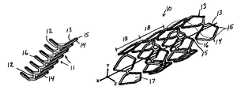
- FIGS. 7A and 7Bare, respectively, perspective views of a portion of a vascular prosthesis of the present invention, uncoiled and flattened, in the deployed and delivery configurations;
- FIGS. 8A and 8Bare, respectively, perspective views of a portion of a vascular prosthesis of the present invention in the deployed and delivery configurations;
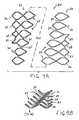
- FIGS. 9A and 9Bare, respectively, perspective views of an alternative vascular prosthesis of the present invention, uncoiled and flattened, in the deployed and delivery configurations;
- FIGS. 10A and 10Bare, respectively, perspective views of a further alternative prosthesis of the present invention, uncoiled and flattened, in deployed and delivery configurations;
- FIGS. 11A and 11Bare, respectively, a perspective view and a cross sectional view of a visualization catheter suitable for use with the vascular prosthesis of the present invention
- FIGS. 12A-12Fillustrate a method of implanting a vascular prosthesis constructed in accordance with the principles of the present invention.
- the present inventionis directed to a vascular prosthesis having a helical configuration and formed of a plurality of bistable cells.
- the bistable mode of operation of the vascular prosthesis (hereinafter also referred to as a “stent”) of the present inventioncombines the superior fatigue resistance of previously known self-expanding helical stents with the superior resistance to radial compressive forces and positive fixation characteristics of previously known plastically deformable stents. The result is a vascular prosthesis having high radial strength, improved resistance to fatigue fracture and low potential for migration.
- the vascular prosthesis of the present inventionis expected to be especially advantageous when deployed in blood vessels subject to dynamic loading, such as the superficial femoral artery. Attempts to use self-expanding helical stents and plastically deformable stents in such vessels often resulted in stent failure, due either to fatigue fracture from cyclic axial loading, migration or both.
- FIG. 1an illustrative application for the stent of the present invention is described for treating occlusive disease of the superficial femoral artery, SFA.
- SFAsuperficial femoral artery
- the location of the SFA in a lower extremityis depicted in relation to femur F, patella P, tibia T, and fibula FB.
- SFApasses posteriorly to the bones of the knee.
- the SFAis subjected to varying degrees of tension and compression. It is this cyclic axial loading that is believed to be the cause of failure of previously known stenting attempts in the SFA.
- FIGS. 2 and 3loading of the SFA in a healthy patient is now described.
- a healthy patient's legis shown with the knee fully extending, such as when the patient is standing.
- the SFAis pulled to a straightened, elongated shape and is subjected to tensile forces, as depicted by the arrows in FIG. 2B .
- tensile loadingalso tends to reduce the diameter of the vessel slightly.
- a relatively stiff plaquebuilds up on the interior of the vessel.
- This stiffening of the arteriesmay lead to reduced elasticity of the vessel in both the radial and longitudinal directions, thereby substantially reducing the ability of the vessel to cope with cyclical loading.
- the plaque build-up within the blood vesseltypically varies in thickness along the length and circumference of the vessel, the vessel is prone to react non-uniformly to tensile and compressive loads.
- FIGS. 4A and 4Bschematically depict how a calcified SFA reacts to the compressive loads applied by flexing of the knee.
- the forces applied to the blood vesseltransition from tension to compression.
- the plaque depositsprevent radial expansion and uniform shortening of the vessel under compressive loading, the vessel tends to deform and become distorted along its longitudinal axis. As a result, localized regions of the vessel are subjected to concentrated bending and/or compressive loads.
- FIG. 4Cillustrates the effect of implanting a previously known plastically deformable stent in the vessel of FIGS. 4A and 4B , for example, to relieve ischemia of the lower limbs.
- the region in which the stent is implantedbecomes essentially rigid in both the axial and radial directions. Consequently, when the blood vessel shortens during flexion of the lower extremity, other portions of the SFA compensate for the rigidity of the stented region by incurring greater distortions and deformations.
- the increased rigidity of the stented regionalso tends to concentrate vessel bending and distortion near the ends of the stent, thereby increasing the demands on the vessel as well as exacerbating the localized forces applied to the vessel. This may result in the formation of a flow-limiting kink in the vessel.
- a self-expanding helical stentis subjected to repetitive axial loading, localized changes in the diameter of the vessel may cause the diameter of the helical stent to fluctuate. This in turn may cause adjacent turns of the stent helix to shift, with the result that, after many cycles of loading, the stent may migrate from its original deployment site. In densely calcified regions the adjacent cell may tilt and limit flow in the vessel due to concentric focal stress on the stent.
- the vascular prosthesis of the present deviceaddresses these problems of previously known stent designs by providing a vascular prosthesis having high longitudinal flexibility, but which provides high radial strength.
- the bistable cells of the vascular prosthesis of the present inventionprovide high radial strength to cope with radial cyclical loads, configured in a helical arrangement that provides axial compressibility and high fracture resistance.
- FIG. 5Adepicts rod 1 having length L and fixed at either end.
- rod 1As rod 1 is compressed in the axial direction, it reaches its buckling stress, shown in FIG. 5B , at which the central part of the rod bows outward in a sidewards direction, to either position 2 or 3 (shown in dotted lines in FIG. 5B ).
- FIG. 5BWhen the axial displacement ⁇ L of the ends of rod 1 is held stable by external clamps 4 , it is possible to move the central section of the rod between the two stable positions 2 and 3 . This movement is in a direction X, perpendicular to the longitudinal axis A-A of the rod. All positions between stable positions 2 and 3 are unstable.
- FIG. 5Bshows a second order curvature in rod 1 , which occurs when the rotation over angle ⁇ is opposed by clamping the central part of rod 1 and maintaining this part parallel to axis A-A.
- force F required to move the central part of rod 1 through displacement Xis plotted as a function of displacement X, with X displayed in the horizontal direction.
- force Fincreases rapidly from zero to F max .
- F maxthe first or second order curvature of FIG. 5B or 5 C
- Further displacement in direction Xrequires less force, because the system has a negative spring rate. The force even becomes zero in the mid position, so that further movement occurs automatically.
- This bistable mode of operationmay be accomplished by creating a unit cell in which a thin strut is coupled at its ends to a thick strut, so that the thick strut serves the function of the external clamps 4 of FIGS. 5B and 5C .
- the thin strutthus will be capable of moving between first and second stable positions via application of an external force, but will be unstable at any intermediate position.
- the resulting unit cellsmay be formed into a tubular structure, so that the application of a radially outward force causes the unit cells to expand from a contracted position, in which the thin strut lies adjacent to the thick strut, to an expanded position in which the thin strut is bowed away from the thick strut.
- Vascular prosthesis 10is depicted in FIG. 7 unrolled and flattened, e.g., as cut from a sheet of shape memory material, while in FIG. 8 , the prosthesis 10 is shown after suitable forming and heat treatment so that the unit cells assume a helical configuration.
- Prosthesis device 10comprises plurality of unit cells 11 interconnected by bridges 12 . Each unit cell 11 comprises thin strut 13 coupled at its ends to thin strut 14 . In accordance with the principles of the present invention, unit cells 11 are bistable.
- unit cells 11have two stable configurations: an expanded, fully deployed configuration ( FIG. 7A ) and a collapsed, fully contracted delivery configuration ( FIG. 7B ).
- Unit cells 11resist any force that deform the cells to an intermediate position, until the applied force reaches F max , at which the cells transition to the other stable position.
- the force required to transition thin strut 13 from the delivery configuration to the deployed configurationis a function of the geometry of the cell, the material from which the cell is constructed, and the processing method used to manufacture the prosthesis.
- the bistable functionality of the unit cellis strongly influenced by the ratio of the thickness of thin strut 13 to thick strut 14 , and thickness ratios of 1:2 to 1:5 are expected to provide good bistable functionality.
- Prosthesis 10may be formed by laser cutting or chemically etching a tube of nickel-titanium alloy or other shape-memory alloy, or alternatively, may be constructed from stainless steel, or other material, such as a biocompatible or biodegradable polymer. Alternatively, prosthesis 10 may be cut or etched from a flat sheet of material, and then formed into a helical tubular member using a mandrel and suitable heat treatments, which are per se known.
- Adjacent unit cells 11are interconnected by bridges 12 offset from one another, so that the unit cells define a helical tubular member.
- the unit cellsare dimensioned so that a predetermined number of cells are disposed in a single turn of the helix and form a substantially smooth lumen when deployed in a target vessel.
- each turn of the helix of prosthesis 10 of FIG. 8comprises six unit cells, although a greater or lesser number may be used as appropriate for a specific application or vessel.
- each unit cell 11comprises distal tip 15 and proximal tip 16 , each formed by the junction of the thin and thick struts.
- the portions of the unit cell that join to form distal tip 15are longer, and form a more acute angle, than the portions that join to form proximal tip 16 . It should be understood, however, that the bistable mode of operation may be achieved with unit cells in which the distal and proximal tips are symmetric or even reversed.
- the junctions of the thin and thick strutsmay be configured to permit transition of the thin strut from the delivery configuration to the deployed configuration with either plastic deformation or alternatively elastically, i.e., with little or no plastic deformation.
- Each unit cell 11when transitioned to the deployed configuration, defines aperture 17 , bounded by thin strut 13 and thick strut 14 .
- thin strut 13lies adjacent to thick strut 14 , thereby reducing the overall diameter of the prosthesis in the delivery configuration.
- transitioning unit cells 11 from the delivery configuration to the deployed configurationadvantageously provides circumferential expansion, without foreshortening of the prosthesis.
- the distal and proximal tips of unit cells 11preferably are aligned with longitudinal axis of the lumen formed by the helix.
- prosthesis 10 of the present inventionmay comprise any number of unit cells interconnected to form a helix having a plurality of turns.
- the length of prosthesis 10may be selected as appropriate for a specific treatment site or application, and may contain as many unit cells as necessary to provide the desired number of helical turns 18 in the helix.
- distal tips 15 of one turn 18 of the helixare spaced apart a predetermined distance from proximal tips 16 of unit cells 11 of the adjacent turn 18 , so that the gap between adjacent turns 18 provides longitudinal flexibility and the ability to withstand compressive loads with the proximal and distal tips of adjacent turns contacting. This gap may be increased further by arranging the unit cells so that distal tips 15 and proximal tips 16 interdigitate.
- Prosthesis 10may be disposed over a balloon catheter (not shown) inserted along longitudinal axis X, and then crimped down by applying an inwardly directed external force greater than F max , so that the unit cells transition to the delivery configuration depicted in FIG. 8A .
- a suitable delivery catheter for use with prosthesis 10may comprise any commercially available catheter having a non-compliant or semi-compliant balloon with or without an external protective sheath, as are well-known in the art.
- the balloonis inflated to apply a radially outwardly directed force to the interior surface of the unit cells.
- force applied to the internal surface of the helix of FIG. 8Aexceeds F max , the thin struts will buckle and transition to the fully expanded deployed configuration of FIG. 8B .
- the cellstransition to the fully deployed configuration with little or no additional force beyond the transition point, cells 11 will become affixed to the interior surface of the target vessel without the overextension and subsequent recoil experienced with previously-known plastically deformable stents. This in turn is expected to reduce trauma to the vessel lining, and reduce the injury-response mechanism that can lead to neointimal hyperplasia.
- distal tip 15 of a cell in one turn 18 of the helixis disposed adjacent to proximal tip 16 of a cell in the adjacent turn 18 . It will be appreciated that if there is not a whole number of cells 11 in each turn, distal tips 15 will be offset from proximal tips 16 of adjoining turns 18 . For example, if there were six-and-one-half cells 11 per turn 18 , distal tips 15 of adjoining turns 18 would be staggered relative to proximal tips 16 .
- the pitch of the helix formed by unit cells 11may be selected by the design of the cell geometry and placement of bridges 12 to provide a predetermined gap between the distal and proximal tips of adjacent turns.
- prosthesis 10may be designed for any desired degree of axial flexibility and to accommodate longitudinal displacements between adjacent turns resulting from axially compressive forces.
- FIG. 9an alternative embodiment of the prosthesis of the present invention is described, wherein the terminal turns of the prosthesis include additional cells that form annular ends when the prosthesis is deployed within a vessel.
- prosthesis 20has been unrolled and flattened, whereas in use the prosthesis would be rolled into helical shape.
- Prosthesis 20comprises a series of intermediate turns 21 (similar to prosthesis 10 ) coupled between proximal and distal terminal turns 22 and 23 , respectively.
- Each of the proximal and distal terminal turnscomprises a plurality of unit cells 24 coupled by bridges 25 , similar to unit cells 11 and bridges 12 of the embodiment of FIGS. 7 and 8 .
- Unit cells 24 and bridges 25are configured as described with respect to the embodiment of FIGS. 7 and 8 , and operate in a bistable manner as described herein above.
- each of terminal turns 22 and 23 of prosthesis 20includes additional cells 26 , 27 , 28 and 29 .
- Proximal terminal turn 22further includes elongated proximal end 30
- distal terminal turn 23further includes elongated distal end 31 .
- additional cells 25 - 28 and elongated proximal and distal ends 30 and 31form annular end regions that provide improved circumferential distribution of forces and thus improved radial strength at the ends of the stent.
- unit cells 24 and additional cells 26 - 29are shown in the fully deployed configuration.
- unit cells of distal terminal end 23are shown in the fully collapsed delivery configuration.
- Elongated proximal end 30 and elongated distal end 31comprise longitudinal extensions of the respective junction of the thin and thick struts of the corresponding unit cells.
- Additional cells 25 - 27are closed articulating structures configured as bistable cells, while cell 28 is merely an open articulating structure.
- Methods of disposing prosthesis 20 on a balloon catheter and implanting the prosthesis at a desired location within a vesselare similar to those described above for the embodiment of FIGS. 7 and 8 .
- Prosthesis 40is shown in FIG. 10 unrolled and flattened, although in use it would be rolled to form a helical structure.
- Prosthesis 40comprises plurality of bistable unit cells 41 connected by bridges 42 .
- Each unit cell 41comprises thin arcuate strut 43 coupled at its ends to thick arcuate strut 44 to form distal and proximal ends 45 and 46 , respectively.
- bridges 42connect thick strut 44 of one cell to the thin strut of the adjacent cell 43 .
- the adjacent cellscould be reversed, so that alternating bridges extend between adjacent pairs of thin or thick struts.
- prosthesis 40forms a series helix having a plurality of adjacent turns. Due to the bistable nature of the unit cells, prosthesis 40 may be compressed onto the balloon of a catheter, and delivered percutaneously to a desired treatment site. Once disposed within a target portion of a vessel or lesion, the balloon may be inflated to transition unit cells 41 from the fully collapsed delivery configuration to the fully expanded deployed configuration.
- prosthesis 40may be accomplished by varying the height and width of the unit cells, the length or placement of bridges 42 and/or the pitch of adjacent turns of the helix. In this manner, unit cells 41 of adjacent turns may be caused to interdigitate, so that distal ends 45 of cells 41 in one turn may be positioned between proximal ends 45 of cells 41 in the adjacent turn.
- the distal and proximal turns of the prosthesis 40may include additional cells or elongated portions, similar to those of the embodiment of FIG. 9 , to improve the circumferential force distribution and radial strength of the ends of the prosthesis.
- Prosthesis 40optionally may further include radiopaque markers 47 disposed on distal and/or proximal ends 45 and 46 , or elsewhere on the stent, such as on bridges 42 .
- prosthesismay include a polymeric coating containing drugs or other bioactive agents for delivery into the vessel wall or to prevent restenosis.
- prosthesis 40may include drug-loaded dimples or pockets formed in thick struts 44 to provide intravascular drug delivery, without affecting the bistable mode of operation of the prosthesis.
- a visualization catheteris provided for use in visualizing the target location for implantation of the vascular prostheses described above.
- visualization catheter 50is configured to assist in placing a guide wire contralaterally across the iliac bifurcation and to provide localized delivery of contrast agent to an intended treatment site.
- Visualization catheter 50comprises flexible elongated body 51 having distal end 52 and proximal end 53 .
- Tapered portion 54is located near distal end 52 , and preferably includes one or more radiopaque markers 55 , which may comprise a series of circumferential rings disposed along tapered portion 54 .
- Catheter 50further includes means for articulating distal end 52 , such as pull wire 56 disposed in lumen 57 ( FIG. 11B ). Pull wire is anchored off-center within distal end 52 and extends proximally through lumen 57 to lever 58 .
- Proximal end 53also includes contrast injection port 59 , which is coupled via lumen 60 to one or more outlet ports 61 disposed in distal end 52 .
- Lumen 62extends from the hemostatic port 63 at proximal end 53 to outlet 64 at distal end 52 , and is adapted to accommodate a conventional guide wire 80 .
- Lumen 60provides fluid communication between contrast injection port 59 and outlet ports 61 .
- One or more outlet ports 61preferably are disposed in the vicinity of tapered portion 54 , and more preferably are disposed on either side of radiopaque markers 55 .
- Catheter 50preferably is constructed of biocompatible materials such as are routinely used in the manufacture of angioplasty and stent delivery catheters.
- Lever 58is configured to permit the clinician to deflect distal end 52 of catheter 50 to route guide wire 80 downward across the iliac bifurcation into the contralateral limb. As discussed in greater detail below, once the catheter is inserted through femoral artery in a patient's leg so that distal end is advanced past the iliac bifurcation, lever 58 may be actuated to direct outlet 64 into the contralateral artery.
- visualization cathetermay include lighting and/or visualization devices, such as fiber optic cables, CCD or CMOS devices, or other known technology used to visualize the interior of a body vessel.
- lighting and/or visualization devicessuch as fiber optic cables, CCD or CMOS devices, or other known technology used to visualize the interior of a body vessel.
- vascular prosthesis 10 of FIGS. 7 and 8is implanted within a patient's partially-occluded left superficial femoral artery to restore patency to the vessel and relieve ischemia of the lower limb.
- guide wire 80is retracted within distal end 52 .
- Lever 58then is retracted proximally so that pull wire 56 causes distal end 52 to deflect so that outlet 64 is directed into the left iliac artery, as depicted in FIG. 12B .
- Guide wire 80is advanced into the patient's left iliac artery, lever 58 is released, and the visualization catheter is advanced along the guide wire into the left SFA until tapered portion 54 crosses lesion L, as may be determined using fluoroscopic visualization.
- contrast agent CAWhen tapered portion 54 is disposed across the lesion, the clinician injects contrast agent CA through contrast injection port 59 so that the contrast exists through outlet 62 in distal end 52 , as depicted in FIG. 12C .
- contrast agent CAmay be delivered directly to the treatment site and with minimal dilution, thereby providing better imaging of the lesion topography.
- Known visualization techniquesthen may be employed to measure the location and extent of the lesion, for example, by comparing the size of the lesion to the known dimensions of markings 55 . The clinician then uses this information to select an appropriately sized vascular prosthesis and delivery catheter. Once the location and size of the lesion has been established, guide wire 80 may be exchanged for a filter-tipped guide wire 90 , and visualization catheter 50 then is withdrawn.
- the delivery catheter and prosthesisare advanced along the filter-tipped guide wire until the stent is disposed across the lesion.
- prosthesis 10is disposed in the fully collapsed configuration on balloon 95 of delivery catheter 96 .
- delivery catheteralso comprises exterior sheath 97 , although the sheath may be omitted.
- the delivery catheteris then advanced along guide wire 90 until prosthesis 10 is disposed across the lesion, and then sheath 97 is retracted proximally to expose stent 10 , as depicted in FIG. 12D .
- Balloon 95then is inflated to transition prosthesis 10 to the fully expanded deployed configuration, as shown in FIG. 12E .
- the ballooninflates, it applies a radially directed outward force to the interior surface of the prosthesis until the force in the thin struts of the unit cells reaches F max at which point the cells of prosthesis 10 “snap” to the fully expanded deployed configuration.
- F maxthe force in the thin struts of the unit cells reaches F max at which point the cells of prosthesis 10 “snap” to the fully expanded deployed configuration.
- prosthesis 10engages the wall of the vessel without overexpansion or recoil, thereby avoiding the trauma associated with delivery of previously known plastically deformable stents.
- balloon 95is deflated and conventional imaging techniques may be employed to verify placement of the prosthesis, for example, using radiopaque markers 47 incorporated into the prosthesis.
- Delivery catheter 96then is removed, and filter-tipped guide wire 90 then also may be withdrawn, leaving prosthesis 10 deployed in the left SFA, as depicted in FIG. 12F .
Landscapes
- Health & Medical Sciences (AREA)
- Engineering & Computer Science (AREA)
- Biomedical Technology (AREA)
- Life Sciences & Earth Sciences (AREA)
- General Health & Medical Sciences (AREA)
- Veterinary Medicine (AREA)
- Public Health (AREA)
- Animal Behavior & Ethology (AREA)
- Heart & Thoracic Surgery (AREA)
- Oral & Maxillofacial Surgery (AREA)
- Transplantation (AREA)
- Vascular Medicine (AREA)
- Cardiology (AREA)
- Pulmonology (AREA)
- Surgery (AREA)
- Gastroenterology & Hepatology (AREA)
- Physics & Mathematics (AREA)
- Optics & Photonics (AREA)
- Molecular Biology (AREA)
- Medical Informatics (AREA)
- Nuclear Medicine, Radiotherapy & Molecular Imaging (AREA)
- Chemical & Material Sciences (AREA)
- Epidemiology (AREA)
- Dermatology (AREA)
- Medicinal Chemistry (AREA)
- Inorganic Chemistry (AREA)
- Biophysics (AREA)
- Anesthesiology (AREA)
- Hematology (AREA)
- Prostheses (AREA)
- Media Introduction/Drainage Providing Device (AREA)
- Materials For Medical Uses (AREA)
Abstract
Description
Claims (51)
Priority Applications (13)
| Application Number | Priority Date | Filing Date | Title |
|---|---|---|---|
| US11/391,940US8353948B2 (en) | 1997-01-24 | 2006-03-29 | Fracture-resistant helical stent incorporating bistable cells and methods of use |
| AU2007243708AAU2007243708B2 (en) | 2006-03-29 | 2007-03-23 | Fracture-resistant helical stent incorporating bistable cells and methods of use |
| ES07753961.7TES2524336T3 (en) | 2006-03-29 | 2007-03-23 | Helical fracture resistant stent incorporating bistable cells |
| KR1020087026197AKR101365548B1 (en) | 2006-03-29 | 2007-03-23 | Fracture-resistant helical stent incorporating bistable cells and methods of use |
| RU2008138267/14ARU2008138267A (en) | 2006-03-29 | 2007-03-23 | Tear-Resistant SPIRAL STENT CONTAINING BISTABLE CELLS AND WAYS OF ITS USE |
| EP07753961.7AEP1998714B1 (en) | 2006-03-29 | 2007-03-23 | Fracture-resistant helical stent incorporating bistable cells |
| CN201110152706.6ACN102232884B (en) | 2006-03-29 | 2007-03-23 | Fracture-resistant helical stent incorporating bistable cells |
| CA2647305ACA2647305C (en) | 2006-03-29 | 2007-03-23 | Fracture-resistant helical stent incorporating bistable cells and methods of use |
| JP2009502907AJP2009531135A (en) | 2006-03-29 | 2007-03-23 | Fracture resistant helical stent incorporating a bistable cell and method of use |
| PCT/US2007/007377WO2007126729A2 (en) | 2006-03-29 | 2007-03-23 | Fracture-resistant helical stent incorporating bistable cells and methods of use |
| CN2007800155509ACN101431964B (en) | 2006-03-29 | 2007-03-23 | Fracture-resistant helical support including bistable cells |
| JP2014151979AJP5960204B2 (en) | 2006-03-29 | 2014-07-25 | Prosthesis, kit for treating obstructive diseases of the body's blood vessels |
| JP2015186601AJP6105697B2 (en) | 2006-03-29 | 2015-09-24 | Prosthesis |
Applications Claiming Priority (4)
| Application Number | Priority Date | Filing Date | Title |
|---|---|---|---|
| US3635997P | 1997-01-24 | 1997-01-24 | |
| US09/012,843US6488702B1 (en) | 1997-01-24 | 1998-01-23 | Bistable spring construction for a stent and other medical apparatus |
| US10/270,771US7828836B2 (en) | 1997-01-24 | 2002-10-11 | Bistable spring construction for a stent and other medical apparatus |
| US11/391,940US8353948B2 (en) | 1997-01-24 | 2006-03-29 | Fracture-resistant helical stent incorporating bistable cells and methods of use |
Related Parent Applications (1)
| Application Number | Title | Priority Date | Filing Date |
|---|---|---|---|
| US10/270,771Continuation-In-PartUS7828836B2 (en) | 1997-01-24 | 2002-10-11 | Bistable spring construction for a stent and other medical apparatus |
Publications (2)
| Publication Number | Publication Date |
|---|---|
| US20060217795A1 US20060217795A1 (en) | 2006-09-28 |
| US8353948B2true US8353948B2 (en) | 2013-01-15 |
Family
ID=38655994
Family Applications (1)
| Application Number | Title | Priority Date | Filing Date |
|---|---|---|---|
| US11/391,940Expired - Fee RelatedUS8353948B2 (en) | 1997-01-24 | 2006-03-29 | Fracture-resistant helical stent incorporating bistable cells and methods of use |
Country Status (10)
| Country | Link |
|---|---|
| US (1) | US8353948B2 (en) |
| EP (1) | EP1998714B1 (en) |
| JP (3) | JP2009531135A (en) |
| KR (1) | KR101365548B1 (en) |
| CN (2) | CN102232884B (en) |
| AU (1) | AU2007243708B2 (en) |
| CA (1) | CA2647305C (en) |
| ES (1) | ES2524336T3 (en) |
| RU (1) | RU2008138267A (en) |
| WO (1) | WO2007126729A2 (en) |
Cited By (13)
| Publication number | Priority date | Publication date | Assignee | Title |
|---|---|---|---|---|
| US9333074B2 (en) | 2009-04-15 | 2016-05-10 | Edwards Lifesciences Cardiaq Llc | Vascular implant and delivery system |
| US9339377B2 (en) | 2008-09-29 | 2016-05-17 | Edwards Lifesciences Cardiaq Llc | Body cavity prosthesis |
| US9554897B2 (en) | 2011-04-28 | 2017-01-31 | Neovasc Tiara Inc. | Methods and apparatus for engaging a valve prosthesis with tissue |
| US9572665B2 (en) | 2013-04-04 | 2017-02-21 | Neovasc Tiara Inc. | Methods and apparatus for delivering a prosthetic valve to a beating heart |
| US9597183B2 (en) | 2008-10-01 | 2017-03-21 | Edwards Lifesciences Cardiaq Llc | Delivery system for vascular implant |
| US9681951B2 (en) | 2013-03-14 | 2017-06-20 | Edwards Lifesciences Cardiaq Llc | Prosthesis with outer skirt and anchors |
| US9713529B2 (en) | 2011-04-28 | 2017-07-25 | Neovasc Tiara Inc. | Sequentially deployed transcatheter mitral valve prosthesis |
| US9770329B2 (en) | 2010-05-05 | 2017-09-26 | Neovasc Tiara Inc. | Transcatheter mitral valve prosthesis |
| US10016275B2 (en) | 2012-05-30 | 2018-07-10 | Neovasc Tiara Inc. | Methods and apparatus for loading a prosthesis onto a delivery system |
| US10583002B2 (en) | 2013-03-11 | 2020-03-10 | Neovasc Tiara Inc. | Prosthetic valve with anti-pivoting mechanism |
| US10767032B2 (en)* | 2016-06-02 | 2020-09-08 | The Royal Institution For The Advancement Of Learning/Mcgill University | Bistable auxetics |
| US20210322223A1 (en)* | 2014-12-01 | 2021-10-21 | Staton Techiya Llc | Fixation methods for devices in tubular structures |
| US11223919B2 (en) | 2014-12-01 | 2022-01-11 | Staton Techiya, Llc | Fixation methods for traversing ear canals |
Families Citing this family (49)
| Publication number | Priority date | Publication date | Assignee | Title |
|---|---|---|---|---|
| US8663311B2 (en)* | 1997-01-24 | 2014-03-04 | Celonova Stent, Inc. | Device comprising biodegradable bistable or multistable cells and methods of use |
| ATE306873T1 (en)* | 1997-01-24 | 2005-11-15 | Kentucky Oil N V | BISTABLE SPRING STRUCTURE FOR A STENT |
| JP3382885B2 (en) | 1999-06-02 | 2003-03-04 | 山口日本電気株式会社 | Ion implantation apparatus and ion implantation method |
| US6799637B2 (en) | 2000-10-20 | 2004-10-05 | Schlumberger Technology Corporation | Expandable tubing and method |
| NO335594B1 (en) | 2001-01-16 | 2015-01-12 | Halliburton Energy Serv Inc | Expandable devices and methods thereof |
| DE10154163A1 (en) | 2001-11-03 | 2003-05-22 | Advanced Med Tech | Device for straightening and stabilizing the spine |
| CA2857815C (en)* | 2005-12-30 | 2016-10-11 | C.R. Bard Inc. | Stent with bio-resorbable connector and methods |
| US8277501B2 (en)* | 2007-12-21 | 2012-10-02 | Boston Scientific Scimed, Inc. | Bi-stable bifurcated stent petal geometry |
| GB0804654D0 (en) | 2008-03-13 | 2008-04-16 | Smith & Nephew | Vacuum closure device |
| WO2010014510A1 (en)* | 2008-07-31 | 2010-02-04 | Boston Scientific Scimed, Inc. | Coils for vascular implants or other uses |
| US9539120B2 (en)* | 2008-10-10 | 2017-01-10 | Veryan Medical Ltd. | Medical device suitable for location in a body lumen |
| JP2012505003A (en)* | 2008-10-10 | 2012-03-01 | ヴェリヤン・メディカル・リミテッド | Medical devices suitable for placement in body cavities |
| KR101085014B1 (en)* | 2009-02-27 | 2011-11-21 | 연세대학교 산학협력단 | Optical surface measuring device and method |
| US10456276B2 (en)* | 2009-05-08 | 2019-10-29 | Veryan Medical Limited | Medical device suitable for location in a body lumen |
| EP2456481B1 (en)* | 2009-07-24 | 2016-11-23 | Boston Scientific Scimed, Inc. | Medical devices having an inorganic coating layer formed by atomic layer deposition |
| US20110066223A1 (en)* | 2009-09-14 | 2011-03-17 | Hossainy Syed F A | Bioabsorbable Stent With Time Dependent Structure And Properties |
| US8425587B2 (en) | 2009-09-17 | 2013-04-23 | Abbott Cardiovascular Systems Inc. | Method of treatment with a bioabsorbable stent with time dependent structure and properties and regio-selective degradation |
| KR101137896B1 (en)* | 2009-11-12 | 2012-05-02 | 연세대학교 산학협력단 | Branch Vessel Protection Stent on Branch Lesions |
| US9421132B2 (en) | 2011-02-04 | 2016-08-23 | University Of Massachusetts | Negative pressure wound closure device |
| US9254212B2 (en) | 2012-04-06 | 2016-02-09 | Abbott Cardiovascular Systems Inc. | Segmented scaffolds and delivery thereof for peripheral applications |
| EP2852419B1 (en) | 2012-05-22 | 2019-11-20 | Smith & Nephew plc | Wound closure device |
| EP2852333B1 (en) | 2012-05-22 | 2021-12-15 | Smith & Nephew plc | Apparatuses for wound therapy |
| AU2013264937B2 (en) | 2012-05-24 | 2018-04-19 | Smith & Nephew Inc. | Devices and methods for treating and closing wounds with negative pressure |
| MX369689B (en) | 2012-07-16 | 2019-11-19 | Smith & Nephew Inc | Negative pressure wound closure device. |
| US8834556B2 (en) | 2012-08-13 | 2014-09-16 | Abbott Cardiovascular Systems Inc. | Segmented scaffold designs |
| US10124098B2 (en) | 2013-03-13 | 2018-11-13 | Smith & Nephew, Inc. | Negative pressure wound closure device and systems and methods of use in treating wounds with negative pressure |
| BR112015021123A2 (en) | 2013-03-14 | 2017-07-18 | Smith & Nephew | compressible wound fillers and systems and methods for use in treating negative pressure injuries |
| CA2918157A1 (en) | 2013-07-16 | 2015-01-22 | Smith & Nephew Plc | Apparatus for wound therapy |
| US9717609B2 (en) | 2013-08-01 | 2017-08-01 | Abbott Cardiovascular Systems Inc. | Variable stiffness stent |
| CN106170275B (en) | 2013-10-21 | 2021-05-07 | 史密夫和内修有限公司 | Negative pressure wound closure device |
| AU2015208299B2 (en) | 2014-01-21 | 2019-11-21 | Smith & Nephew Plc | Collapsible dressing for negative pressure wound treatment |
| EP3096725B1 (en) | 2014-01-21 | 2023-10-18 | Smith & Nephew plc | Wound treatment apparatuses |
| AU2016254119A1 (en) | 2015-04-29 | 2017-10-05 | Smith & Nephew Inc. | Negative pressure wound closure device |
| DE102015111019B4 (en)* | 2015-07-08 | 2021-02-18 | Acandis Gmbh | Medical device for endovascular treatment |
| US11471586B2 (en) | 2015-12-15 | 2022-10-18 | University Of Massachusetts | Negative pressure wound closure devices and methods |
| JP7038701B2 (en) | 2016-08-30 | 2022-03-18 | スミス アンド ネフュー ピーエルシー | System for applying decompression therapy |
| US11096832B2 (en) | 2016-09-27 | 2021-08-24 | Smith & Nephew Plc | Wound closure devices with dissolvable portions |
| CN110167495B (en) | 2016-11-02 | 2022-06-14 | 史密夫和内修有限公司 | Wound closure device |
| US10966849B2 (en) | 2017-03-08 | 2021-04-06 | Yamaguchi University | Indwelling medical device having bistable structure in lumen organ |
| WO2018229009A1 (en)* | 2017-06-13 | 2018-12-20 | Smith & Nephew Plc | Wound closure device and method of use |
| EP3638169B1 (en) | 2017-06-13 | 2024-11-13 | Smith & Nephew PLC | Collapsible structure and method of use |
| US11123476B2 (en) | 2017-06-14 | 2021-09-21 | Smith & Nephew, Inc. | Fluid removal management and control of wound closure in wound therapy |
| WO2018231874A1 (en) | 2017-06-14 | 2018-12-20 | Smith & Nephew, Inc. | Control of wound closure and fluid removal management in wound therapy |
| WO2018229011A1 (en) | 2017-06-14 | 2018-12-20 | Smith & Nephew Plc | Collapsible structure for wound closure and method of use |
| AU2018285239B2 (en) | 2017-06-14 | 2023-09-21 | Smith & Nephew Plc | Collapsible sheet for wound closure and method of use |
| WO2019020544A1 (en) | 2017-07-27 | 2019-01-31 | Smith & Nephew Plc | Customizable wound closure device and method of use |
| US11590030B2 (en) | 2017-08-07 | 2023-02-28 | Smith & Nephew Plc | Wound closure device with protective layer and method of use |
| EP3675925A1 (en) | 2017-08-29 | 2020-07-08 | Smith & Nephew PLC | Systems and methods for monitoring wound closure |
| US10932927B2 (en)* | 2018-08-29 | 2021-03-02 | DePuy Synthes Products, Inc. | Stent with longitudinal variable width struts |
Citations (112)
| Publication number | Priority date | Publication date | Assignee | Title |
|---|---|---|---|---|
| US3069125A (en) | 1958-01-20 | 1962-12-18 | Robertshaw Fulton Controls Co | Heat actuated snap acting valve |
| US3508587A (en) | 1966-09-29 | 1970-04-28 | Hans A Mauch | Tubular structural member |
| US3657744A (en) | 1970-05-08 | 1972-04-25 | Univ Minnesota | Method for fixing prosthetic implants in a living body |
| US3898717A (en) | 1972-10-10 | 1975-08-12 | Peyer Siegfried | Releasable paper clip |
| GB2081173A (en) | 1980-07-18 | 1982-02-17 | Behar Yves | Positioning a Flexible Pattern Casting Band in a Spectacle Lens Mount |
| US4580568A (en) | 1984-10-01 | 1986-04-08 | Cook, Incorporated | Percutaneous endovascular stent and method for insertion thereof |
| GB2169515A (en) | 1984-12-31 | 1986-07-16 | Lifeline Ltd | Catheter mount assembly |
| GB2175824A (en) | 1985-05-29 | 1986-12-10 | Barry Rene Christopher Paul | Producing composite metal articles |
| US4655771A (en) | 1982-04-30 | 1987-04-07 | Shepherd Patents S.A. | Prosthesis comprising an expansible or contractile tubular body |
| US4665906A (en) | 1983-10-14 | 1987-05-19 | Raychem Corporation | Medical devices incorporating sim alloy elements |
| US4665918A (en) | 1986-01-06 | 1987-05-19 | Garza Gilbert A | Prosthesis system and method |
| US4733665A (en) | 1985-11-07 | 1988-03-29 | Expandable Grafts Partnership | Expandable intraluminal graft, and method and apparatus for implanting an expandable intraluminal graft |
| US4740207A (en) | 1986-09-10 | 1988-04-26 | Kreamer Jeffry W | Intralumenal graft |
| EP0274846A1 (en) | 1986-12-09 | 1988-07-20 | Boston Scientific Corporation | Apparatus for treating hypertrophy of the prostate gland |
| FR2617721A1 (en) | 1987-07-10 | 1989-01-13 | Nippon Zeon Co | CATHETER |
| EP0326426A2 (en) | 1988-01-28 | 1989-08-02 | JMS Co., Ltd. | Plastic molded articles with shape memory property |
| EP0335341A1 (en) | 1988-03-28 | 1989-10-04 | EXPANDABLE GRAFTS PARTNERSHIP a Texas General Partnership | Expandable intraluminal graft and apparatus for implanting an expandable intraluminal graft |
| DE8812719U1 (en) | 1988-10-11 | 1989-11-09 | Lindenberg, Josef, 7500 Karlsruhe | Device for correcting stenosis |
| US4886062A (en) | 1987-10-19 | 1989-12-12 | Medtronic, Inc. | Intravascular radially expandable stent and method of implant |
| EP0364787A1 (en) | 1988-10-04 | 1990-04-25 | EXPANDABLE GRAFTS PARTNERSHIP a Texas General Partnership | Expandable intraluminal graft |
| FR2642812A1 (en) | 1989-02-08 | 1990-08-10 | Crouzet Sa | Optically controlled piezoelectric fluid switch-over device |
| US4990155A (en) | 1989-05-19 | 1991-02-05 | Wilkoff Howard M | Surgical stent method and apparatus |
| US4994071A (en) | 1989-05-22 | 1991-02-19 | Cordis Corporation | Bifurcating stent apparatus and method |
| EP0421729A2 (en) | 1989-10-02 | 1991-04-10 | Medtronic, Inc. | Articulated stent |
| WO1992006734A1 (en) | 1990-10-18 | 1992-04-30 | Ho Young Song | Self-expanding endovascular stent |
| US5141360A (en) | 1989-09-18 | 1992-08-25 | David Zeman | Irrigation tubing |
| US5147370A (en) | 1991-06-12 | 1992-09-15 | Mcnamara Thomas O | Nitinol stent for hollow body conduits |
| WO1992019310A1 (en) | 1991-04-26 | 1992-11-12 | Advanced Coronary Technology, Inc. | Removable heat-recoverable tissue supporting device |
| US5192307A (en) | 1987-12-08 | 1993-03-09 | Wall W Henry | Angioplasty stent |
| EP0540290A2 (en) | 1991-10-28 | 1993-05-05 | Advanced Cardiovascular Systems, Inc. | Expandable stents and method for making same |
| US5226913A (en)* | 1988-09-01 | 1993-07-13 | Corvita Corporation | Method of making a radially expandable prosthesis |
| US5234448A (en) | 1992-02-28 | 1993-08-10 | Shadyside Hospital | Method and apparatus for connecting and closing severed blood vessels |
| WO1993022986A1 (en) | 1992-05-08 | 1993-11-25 | Schneider (Usa) Inc. | Esophageal stent and delivery tool |
| US5282823A (en)* | 1992-03-19 | 1994-02-01 | Medtronic, Inc. | Intravascular radially expandable stent |
| WO1994003127A1 (en) | 1992-08-06 | 1994-02-17 | William Cook Europe A/S | A prosthetic device for sustaining a blood-vessel or hollow organ lumen |
| EP0587197A1 (en) | 1990-10-13 | 1994-03-16 | Angiomed Ag | Arranging device in a body duct |
| US5383926A (en) | 1992-11-23 | 1995-01-24 | Children's Medical Center Corporation | Re-expandable endoprosthesis |
| US5383892A (en) | 1991-11-08 | 1995-01-24 | Meadox France | Stent for transluminal implantation |
| EP0636345A1 (en) | 1993-07-26 | 1995-02-01 | Sentinel Medical, Inc. | Fluid jet surgical cutting tool |
| US5397355A (en) | 1994-07-19 | 1995-03-14 | Stentco, Inc. | Intraluminal stent |
| US5403341A (en) | 1994-01-24 | 1995-04-04 | Solar; Ronald J. | Parallel flow endovascular stent and deployment apparatus therefore |
| WO1995009584A1 (en) | 1993-10-05 | 1995-04-13 | Guerbet S.A. | Tubular expandable member for an intraluminal endoprosthesis, intraluminal endoprosthesis and method of production |
| US5411507A (en) | 1993-01-08 | 1995-05-02 | Richard Wolf Gmbh | Instrument for implanting and extracting stents |
| EP0664107A1 (en) | 1994-01-19 | 1995-07-26 | NAZARI, Stefano | Vascular prosthesis and device for its application |
| US5449373A (en) | 1994-03-17 | 1995-09-12 | Medinol Ltd. | Articulated stent |
| EP0679372A2 (en) | 1994-04-25 | 1995-11-02 | Advanced Cardiovascular Systems, Inc. | Radiopaque stent markers |
| WO1995031945A1 (en) | 1994-05-19 | 1995-11-30 | Scimed Life Systems, Inc. | Improved tissue supporting devices |
| WO1995032757A1 (en) | 1994-06-01 | 1995-12-07 | Nitinol Medical Technologies, Inc. | A stent and a method of use |
| EP0688545A1 (en) | 1994-06-17 | 1995-12-27 | Terumo Kabushiki Kaisha | Indwelling stent and the method for manufacturing the same |
| WO1996003942A2 (en) | 1994-08-02 | 1996-02-15 | Ram Michael J | Female incontinence device including electronic sensors |
| US5496365A (en) | 1992-07-02 | 1996-03-05 | Sgro; Jean-Claude | Autoexpandable vascular endoprosthesis |
| US5500013A (en) | 1991-10-04 | 1996-03-19 | Scimed Life Systems, Inc. | Biodegradable drug delivery vascular stent |
| WO1996009013A1 (en) | 1994-09-21 | 1996-03-28 | Wake Forest University | Expandable, intraluminal stents |
| US5545210A (en)* | 1994-09-22 | 1996-08-13 | Advanced Coronary Technology, Inc. | Method of implanting a permanent shape memory alloy stent |
| US5545208A (en)* | 1990-02-28 | 1996-08-13 | Medtronic, Inc. | Intralumenal drug eluting prosthesis |
| US5556413A (en) | 1994-03-11 | 1996-09-17 | Advanced Cardiovascular Systems, Inc. | Coiled stent with locking ends |
| WO1996029028A1 (en) | 1995-03-21 | 1996-09-26 | University College London | Expandable surgical stent |
| EP0734698A2 (en) | 1995-04-01 | 1996-10-02 | Variomed AG | Stent for transluminal implantation into hollow organs |
| US5562690A (en) | 1993-11-12 | 1996-10-08 | United States Surgical Corporation | Apparatus and method for performing compressional anastomoses |
| EP0744164A1 (en) | 1995-05-25 | 1996-11-27 | Cook Incorporated | An implantable prosthetic device |
| WO1996041589A1 (en) | 1995-06-13 | 1996-12-27 | William Cook Europe A/S | A device for implantation in a vessel or hollow organ lumen |
| US5601593A (en)* | 1995-03-06 | 1997-02-11 | Willy Rusch Ag | Stent for placement in a body tube |
| WO1997004721A1 (en) | 1995-07-25 | 1997-02-13 | Medstent Inc. | Expandible stent |
| US5628787A (en) | 1993-01-19 | 1997-05-13 | Schneider (Usa) Inc. | Clad composite stent |
| US5643314A (en) | 1995-11-13 | 1997-07-01 | Navius Corporation | Self-expanding stent |
| US5695516A (en) | 1996-02-21 | 1997-12-09 | Iso Stent, Inc. | Longitudinally elongating balloon expandable stent |
| US5697971A (en)* | 1996-06-11 | 1997-12-16 | Fischell; Robert E. | Multi-cell stent with cells having differing characteristics |
| US5733303A (en) | 1994-03-17 | 1998-03-31 | Medinol Ltd. | Flexible expandable stent |
| US5755774A (en) | 1994-06-27 | 1998-05-26 | Corvita Corporation | Bistable luminal graft endoprosthesis |
| US5755776A (en) | 1996-10-04 | 1998-05-26 | Al-Saadon; Khalid | Permanent expandable intraluminal tubular stent |
| US5776183A (en)* | 1996-08-23 | 1998-07-07 | Kanesaka; Nozomu | Expandable stent |
| US5807404A (en)* | 1996-09-19 | 1998-09-15 | Medinol Ltd. | Stent with variable features to optimize support and method of making such stent |
| US5824040A (en)* | 1995-12-01 | 1998-10-20 | Medtronic, Inc. | Endoluminal prostheses and therapies for highly variable body lumens |
| US5871538A (en)* | 1992-12-21 | 1999-02-16 | Corvita Corporation | Luminal graft endoprotheses and manufacture thereof |
| US5891191A (en) | 1996-04-30 | 1999-04-06 | Schneider (Usa) Inc | Cobalt-chromium-molybdenum alloy stent and stent-graft |
| US5895406A (en)* | 1996-01-26 | 1999-04-20 | Cordis Corporation | Axially flexible stent |
| US5899882A (en)* | 1994-10-27 | 1999-05-04 | Novoste Corporation | Catheter apparatus for radiation treatment of a desired area in the vascular system of a patient |
| US5913897A (en)* | 1993-09-16 | 1999-06-22 | Cordis Corporation | Endoprosthesis having multiple bridging junctions and procedure |
| US5922020A (en)* | 1996-08-02 | 1999-07-13 | Localmed, Inc. | Tubular prosthesis having improved expansion and imaging characteristics |
| US5928280A (en) | 1995-09-11 | 1999-07-27 | William Cook Europe A/S | Expandable endovascular stent |
| US6019789A (en) | 1998-04-01 | 2000-02-01 | Quanam Medical Corporation | Expandable unit cell and intraluminal stent |
| US6027527A (en) | 1996-12-06 | 2000-02-22 | Piolax Inc. | Stent |
| US6027526A (en)* | 1996-04-10 | 2000-02-22 | Advanced Cardiovascular Systems, Inc. | Stent having varied amounts of structural strength along its length |
| US6042606A (en) | 1997-09-29 | 2000-03-28 | Cook Incorporated | Radially expandable non-axially contracting surgical stent |
| US6106548A (en) | 1997-02-07 | 2000-08-22 | Endosystems Llc | Non-foreshortening intraluminal prosthesis |
| US6193744B1 (en) | 1998-09-10 | 2001-02-27 | Scimed Life Systems, Inc. | Stent configurations |
| US6203569B1 (en)* | 1996-01-04 | 2001-03-20 | Bandula Wijay | Flexible stent |
| US6206911B1 (en) | 1996-12-19 | 2001-03-27 | Simcha Milo | Stent combination |
| US6261319B1 (en) | 1998-07-08 | 2001-07-17 | Scimed Life Systems, Inc. | Stent |
| US6264685B1 (en) | 1999-07-06 | 2001-07-24 | Datascope Investment Corp. | Flexible high radial strength stent |
| US20010027339A1 (en) | 1997-09-24 | 2001-10-04 | Boatman Scott E. | Radially expandable stent |
| US20010044652A1 (en)* | 1999-10-14 | 2001-11-22 | Moore Brian Edward | Stents with multi-layered struts |
| US6368355B1 (en) | 1998-05-13 | 2002-04-09 | Renan Uflacker | Stent or graft support structure for treating bifurcated vessels having different diameter portions and methods of use and implantation |
| US6485524B2 (en) | 1997-01-31 | 2002-11-26 | Ernst-Peter Strecker | Stent for treating pathological body vessels |
| US6488702B1 (en) | 1997-01-24 | 2002-12-03 | Jomed Gmbh | Bistable spring construction for a stent and other medical apparatus |
| US6540777B2 (en) | 2001-02-15 | 2003-04-01 | Scimed Life Systems, Inc. | Locking stent |
| US20030199969A1 (en) | 1998-02-17 | 2003-10-23 | Steinke Thomas A. | Expandable stent with sliding and locking radial elements |
| US6669718B2 (en) | 1999-11-18 | 2003-12-30 | Petrus Besselink | Apparatus and method for placing bifurcated stents |
| US20040034402A1 (en) | 2002-07-26 | 2004-02-19 | Syntheon, Llc | Helical stent having flexible transition zone |
| US20040088043A1 (en) | 1997-10-03 | 2004-05-06 | Avantec Vascular Corporation | Radially expansible vessel scaffold having modified radiopacity |
| US6755856B2 (en) | 1998-09-05 | 2004-06-29 | Abbott Laboratories Vascular Enterprises Limited | Methods and apparatus for stenting comprising enhanced embolic protection, coupled with improved protection against restenosis and thrombus formation |
| US20040133270A1 (en) | 2002-07-08 | 2004-07-08 | Axel Grandt | Drug eluting stent and methods of manufacture |
| US6772836B2 (en) | 2000-10-20 | 2004-08-10 | Schlumberger Technology Corporation | Expandable tubing and method |
| US20050055080A1 (en) | 2003-09-05 | 2005-03-10 | Naim Istephanous | Modulated stents and methods of making the stents |
| US20050163821A1 (en) | 2002-08-02 | 2005-07-28 | Hsing-Wen Sung | Drug-eluting Biodegradable Stent and Delivery Means |
| US20050182479A1 (en) | 2004-02-13 | 2005-08-18 | Craig Bonsignore | Connector members for stents |
| US20060241739A1 (en) | 1997-01-24 | 2006-10-26 | Paragon Intellectual Properties, Llc | Device comprising biodegradable bistable or multistable cells and methods of use |
| US7235097B2 (en) | 2002-08-07 | 2007-06-26 | Paragon Intellectual Properties, Llc | Apparatus for a stent or other medical device having a bistable spring construction |
| US7291166B2 (en) | 2005-05-18 | 2007-11-06 | Advanced Cardiovascular Systems, Inc. | Polymeric stent patterns |
| US7300458B2 (en) | 2002-07-19 | 2007-11-27 | Micro Therapeutics, Inc. | Medical implant having a curlable matrix structure |
| US20080097571A1 (en) | 2006-10-21 | 2008-04-24 | Paragon Intellectual Properties, Llc | Deformable lumen support devices and methods of use |
| US7476245B2 (en) | 2005-08-16 | 2009-01-13 | Advanced Cardiovascular Systems, Inc. | Polymeric stent patterns |
Family Cites Families (16)
| Publication number | Priority date | Publication date | Assignee | Title |
|---|---|---|---|---|
| US4641654A (en)* | 1985-07-30 | 1987-02-10 | Advanced Cardiovascular Systems, Inc. | Steerable balloon dilatation catheter assembly having dye injection and pressure measurement capabilities |
| US4886061A (en)* | 1988-02-09 | 1989-12-12 | Medinnovations, Inc. | Expandable pullback atherectomy catheter system |
| US5114423A (en)* | 1989-05-15 | 1992-05-19 | Advanced Cardiovascular Systems, Inc. | Dilatation catheter assembly with heated balloon |
| US5683345A (en)* | 1994-10-27 | 1997-11-04 | Novoste Corporation | Method and apparatus for treating a desired area in the vascular system of a patient |
| US5700303A (en)* | 1996-10-31 | 1997-12-23 | Zander; Richard A. | Chrome polish/exhaust pipe de-bluer |
| US6152943A (en)* | 1998-08-14 | 2000-11-28 | Incept Llc | Methods and apparatus for intraluminal deposition of hydrogels |
| US6355059B1 (en)* | 1998-12-03 | 2002-03-12 | Medinol, Ltd. | Serpentine coiled ladder stent |
| AU782484B2 (en)* | 1999-12-02 | 2005-08-04 | Edwards Lifesciences Corporation | Methods and apparatus for delivering medicament to tissue |
| US6423091B1 (en)* | 2000-05-16 | 2002-07-23 | Cordis Corporation | Helical stent having flat ends |
| JP3778786B2 (en)* | 2000-08-04 | 2006-05-24 | 日本ライフライン株式会社 | Stent |
| GB2371066B8 (en)* | 2001-01-16 | 2012-12-19 | Halliburton Energy Serv Inc | Tubulars with expandable cells and locking mechanisms |
| JP2002272855A (en)* | 2001-03-14 | 2002-09-24 | Piolax Medical Device:Kk | Stent |
| DE10237572A1 (en)* | 2002-08-13 | 2004-02-26 | Biotronik Meß- und Therapiegeräte GmbH & Co. Ingenieurbüro Berlin | Stent with a polymer coating |
| JP4481559B2 (en)* | 2002-09-30 | 2010-06-16 | テルモ株式会社 | Stent for living indwelling and organ expansion device |
| US7527632B2 (en)* | 2003-03-31 | 2009-05-05 | Cordis Corporation | Modified delivery device for coated medical devices |
| JP4542360B2 (en)* | 2004-03-30 | 2010-09-15 | テルモ株式会社 | Self-expanding in-vivo stent |
- 2006
- 2006-03-29USUS11/391,940patent/US8353948B2/ennot_activeExpired - Fee Related
- 2007
- 2007-03-23CNCN201110152706.6Apatent/CN102232884B/ennot_activeExpired - Fee Related
- 2007-03-23CACA2647305Apatent/CA2647305C/enactiveActive
- 2007-03-23WOPCT/US2007/007377patent/WO2007126729A2/enactiveApplication Filing
- 2007-03-23RURU2008138267/14Apatent/RU2008138267A/enunknown
- 2007-03-23CNCN2007800155509Apatent/CN101431964B/ennot_activeExpired - Fee Related
- 2007-03-23ESES07753961.7Tpatent/ES2524336T3/enactiveActive
- 2007-03-23AUAU2007243708Apatent/AU2007243708B2/ennot_activeCeased
- 2007-03-23EPEP07753961.7Apatent/EP1998714B1/ennot_activeNot-in-force
- 2007-03-23KRKR1020087026197Apatent/KR101365548B1/ennot_activeExpired - Fee Related
- 2007-03-23JPJP2009502907Apatent/JP2009531135A/ennot_activeWithdrawn
- 2014
- 2014-07-25JPJP2014151979Apatent/JP5960204B2/ennot_activeExpired - Fee Related
- 2015
- 2015-09-24JPJP2015186601Apatent/JP6105697B2/ennot_activeExpired - Fee Related
Patent Citations (138)
| Publication number | Priority date | Publication date | Assignee | Title |
|---|---|---|---|---|
| US3069125A (en) | 1958-01-20 | 1962-12-18 | Robertshaw Fulton Controls Co | Heat actuated snap acting valve |
| US3508587A (en) | 1966-09-29 | 1970-04-28 | Hans A Mauch | Tubular structural member |
| US3657744A (en) | 1970-05-08 | 1972-04-25 | Univ Minnesota | Method for fixing prosthetic implants in a living body |
| US3898717A (en) | 1972-10-10 | 1975-08-12 | Peyer Siegfried | Releasable paper clip |
| GB2081173A (en) | 1980-07-18 | 1982-02-17 | Behar Yves | Positioning a Flexible Pattern Casting Band in a Spectacle Lens Mount |
| US4655771A (en) | 1982-04-30 | 1987-04-07 | Shepherd Patents S.A. | Prosthesis comprising an expansible or contractile tubular body |
| US4655771B1 (en) | 1982-04-30 | 1996-09-10 | Medinvent Ams Sa | Prosthesis comprising an expansible or contractile tubular body |
| US4665906A (en) | 1983-10-14 | 1987-05-19 | Raychem Corporation | Medical devices incorporating sim alloy elements |
| US4580568A (en) | 1984-10-01 | 1986-04-08 | Cook, Incorporated | Percutaneous endovascular stent and method for insertion thereof |
| GB2169515A (en) | 1984-12-31 | 1986-07-16 | Lifeline Ltd | Catheter mount assembly |
| GB2175824A (en) | 1985-05-29 | 1986-12-10 | Barry Rene Christopher Paul | Producing composite metal articles |
| US5102417A (en)* | 1985-11-07 | 1992-04-07 | Expandable Grafts Partnership | Expandable intraluminal graft, and method and apparatus for implanting an expandable intraluminal graft |
| US4733665A (en) | 1985-11-07 | 1988-03-29 | Expandable Grafts Partnership | Expandable intraluminal graft, and method and apparatus for implanting an expandable intraluminal graft |
| US4739762A (en) | 1985-11-07 | 1988-04-26 | Expandable Grafts Partnership | Expandable intraluminal graft, and method and apparatus for implanting an expandable intraluminal graft |
| US4739762B1 (en) | 1985-11-07 | 1998-10-27 | Expandable Grafts Partnership | Expandable intraluminal graft and method and apparatus for implanting an expandable intraluminal graft |
| US4733665C2 (en) | 1985-11-07 | 2002-01-29 | Expandable Grafts Partnership | Expandable intraluminal graft and method and apparatus for implanting an expandable intraluminal graft |
| US4733665B1 (en) | 1985-11-07 | 1994-01-11 | Expandable Grafts Partnership | Expandable intraluminal graft,and method and apparatus for implanting an expandable intraluminal graft |
| US4665918A (en) | 1986-01-06 | 1987-05-19 | Garza Gilbert A | Prosthesis system and method |
| US4740207A (en) | 1986-09-10 | 1988-04-26 | Kreamer Jeffry W | Intralumenal graft |
| EP0274846A1 (en) | 1986-12-09 | 1988-07-20 | Boston Scientific Corporation | Apparatus for treating hypertrophy of the prostate gland |
| FR2617721A1 (en) | 1987-07-10 | 1989-01-13 | Nippon Zeon Co | CATHETER |
| US4969890A (en) | 1987-07-10 | 1990-11-13 | Nippon Zeon Co., Ltd. | Catheter |
| US4886062A (en) | 1987-10-19 | 1989-12-12 | Medtronic, Inc. | Intravascular radially expandable stent and method of implant |
| US5192307A (en) | 1987-12-08 | 1993-03-09 | Wall W Henry | Angioplasty stent |
| EP0326426A2 (en) | 1988-01-28 | 1989-08-02 | JMS Co., Ltd. | Plastic molded articles with shape memory property |
| US4950258A (en) | 1988-01-28 | 1990-08-21 | Japan Medical Supply Co., Ltd. | Plastic molded articles with shape memory property |
| EP0335341A1 (en) | 1988-03-28 | 1989-10-04 | EXPANDABLE GRAFTS PARTNERSHIP a Texas General Partnership | Expandable intraluminal graft and apparatus for implanting an expandable intraluminal graft |
| US5226913A (en)* | 1988-09-01 | 1993-07-13 | Corvita Corporation | Method of making a radially expandable prosthesis |
| US5195984A (en) | 1988-10-04 | 1993-03-23 | Expandable Grafts Partnership | Expandable intraluminal graft |
| EP0364787A1 (en) | 1988-10-04 | 1990-04-25 | EXPANDABLE GRAFTS PARTNERSHIP a Texas General Partnership | Expandable intraluminal graft |
| DE8812719U1 (en) | 1988-10-11 | 1989-11-09 | Lindenberg, Josef, 7500 Karlsruhe | Device for correcting stenosis |
| FR2642812A1 (en) | 1989-02-08 | 1990-08-10 | Crouzet Sa | Optically controlled piezoelectric fluid switch-over device |
| US4990155A (en) | 1989-05-19 | 1991-02-05 | Wilkoff Howard M | Surgical stent method and apparatus |
| US4994071A (en) | 1989-05-22 | 1991-02-19 | Cordis Corporation | Bifurcating stent apparatus and method |
| US5141360A (en) | 1989-09-18 | 1992-08-25 | David Zeman | Irrigation tubing |
| US5104404A (en) | 1989-10-02 | 1992-04-14 | Medtronic, Inc. | Articulated stent |
| EP0421729A2 (en) | 1989-10-02 | 1991-04-10 | Medtronic, Inc. | Articulated stent |
| US5545208A (en)* | 1990-02-28 | 1996-08-13 | Medtronic, Inc. | Intralumenal drug eluting prosthesis |
| EP0587197A1 (en) | 1990-10-13 | 1994-03-16 | Angiomed Ag | Arranging device in a body duct |
| WO1992006734A1 (en) | 1990-10-18 | 1992-04-30 | Ho Young Song | Self-expanding endovascular stent |
| WO1992019310A1 (en) | 1991-04-26 | 1992-11-12 | Advanced Coronary Technology, Inc. | Removable heat-recoverable tissue supporting device |
| US5197978A (en) | 1991-04-26 | 1993-03-30 | Advanced Coronary Technology, Inc. | Removable heat-recoverable tissue supporting device |
| US5197978B1 (en) | 1991-04-26 | 1996-05-28 | Advanced Coronary Tech | Removable heat-recoverable tissue supporting device |
| US5147370A (en) | 1991-06-12 | 1992-09-15 | Mcnamara Thomas O | Nitinol stent for hollow body conduits |
| US5500013A (en) | 1991-10-04 | 1996-03-19 | Scimed Life Systems, Inc. | Biodegradable drug delivery vascular stent |
| EP0540290A2 (en) | 1991-10-28 | 1993-05-05 | Advanced Cardiovascular Systems, Inc. | Expandable stents and method for making same |
| US5383892A (en) | 1991-11-08 | 1995-01-24 | Meadox France | Stent for transluminal implantation |
| US5234448A (en) | 1992-02-28 | 1993-08-10 | Shadyside Hospital | Method and apparatus for connecting and closing severed blood vessels |
| US5282823A (en)* | 1992-03-19 | 1994-02-01 | Medtronic, Inc. | Intravascular radially expandable stent |
| WO1993022986A1 (en) | 1992-05-08 | 1993-11-25 | Schneider (Usa) Inc. | Esophageal stent and delivery tool |
| US5496365A (en) | 1992-07-02 | 1996-03-05 | Sgro; Jean-Claude | Autoexpandable vascular endoprosthesis |
| WO1994003127A1 (en) | 1992-08-06 | 1994-02-17 | William Cook Europe A/S | A prosthetic device for sustaining a blood-vessel or hollow organ lumen |
| US5383926A (en) | 1992-11-23 | 1995-01-24 | Children's Medical Center Corporation | Re-expandable endoprosthesis |
| US5871538A (en)* | 1992-12-21 | 1999-02-16 | Corvita Corporation | Luminal graft endoprotheses and manufacture thereof |
| US5411507A (en) | 1993-01-08 | 1995-05-02 | Richard Wolf Gmbh | Instrument for implanting and extracting stents |
| US5628787A (en) | 1993-01-19 | 1997-05-13 | Schneider (Usa) Inc. | Clad composite stent |
| EP0636345A1 (en) | 1993-07-26 | 1995-02-01 | Sentinel Medical, Inc. | Fluid jet surgical cutting tool |
| US5913897A (en)* | 1993-09-16 | 1999-06-22 | Cordis Corporation | Endoprosthesis having multiple bridging junctions and procedure |
| WO1995009584A1 (en) | 1993-10-05 | 1995-04-13 | Guerbet S.A. | Tubular expandable member for an intraluminal endoprosthesis, intraluminal endoprosthesis and method of production |
| US5861025A (en) | 1993-10-05 | 1999-01-19 | Assistance Publique Hopitaux De Paris | Tubular expandable member for an intraluminal endoprosthesis, intraluminal endoprosthesis, and method of production |
| US5562690A (en) | 1993-11-12 | 1996-10-08 | United States Surgical Corporation | Apparatus and method for performing compressional anastomoses |
| EP0664107A1 (en) | 1994-01-19 | 1995-07-26 | NAZARI, Stefano | Vascular prosthesis and device for its application |
| US5554183A (en) | 1994-01-19 | 1996-09-10 | Nazari; Stefano | Vascular prosthesis for the substitution or internal lining of blood vessels of medium or large diameter and device for its application |
| US5403341A (en) | 1994-01-24 | 1995-04-04 | Solar; Ronald J. | Parallel flow endovascular stent and deployment apparatus therefore |
| US5556413A (en) | 1994-03-11 | 1996-09-17 | Advanced Cardiovascular Systems, Inc. | Coiled stent with locking ends |
| US5449373A (en) | 1994-03-17 | 1995-09-12 | Medinol Ltd. | Articulated stent |
| US5733303A (en) | 1994-03-17 | 1998-03-31 | Medinol Ltd. | Flexible expandable stent |
| US5725572A (en)* | 1994-04-25 | 1998-03-10 | Advanced Cardiovascular Systems, Inc. | Radiopaque stent |
| EP0679372A2 (en) | 1994-04-25 | 1995-11-02 | Advanced Cardiovascular Systems, Inc. | Radiopaque stent markers |
| WO1995031945A1 (en) | 1994-05-19 | 1995-11-30 | Scimed Life Systems, Inc. | Improved tissue supporting devices |
| US6451052B1 (en) | 1994-05-19 | 2002-09-17 | Scimed Life Systems, Inc. | Tissue supporting devices |
| US6582461B1 (en) | 1994-05-19 | 2003-06-24 | Scimed Life Systems, Inc. | Tissue supporting devices |
| WO1995032757A1 (en) | 1994-06-01 | 1995-12-07 | Nitinol Medical Technologies, Inc. | A stent and a method of use |
| EP0688545A1 (en) | 1994-06-17 | 1995-12-27 | Terumo Kabushiki Kaisha | Indwelling stent and the method for manufacturing the same |
| US6013854A (en) | 1994-06-17 | 2000-01-11 | Terumo Kabushiki Kaisha | Indwelling stent and the method for manufacturing the same |
| US5755774A (en) | 1994-06-27 | 1998-05-26 | Corvita Corporation | Bistable luminal graft endoprosthesis |
| US5397355A (en) | 1994-07-19 | 1995-03-14 | Stentco, Inc. | Intraluminal stent |
| WO1996003942A2 (en) | 1994-08-02 | 1996-02-15 | Ram Michael J | Female incontinence device including electronic sensors |
| WO1996009013A1 (en) | 1994-09-21 | 1996-03-28 | Wake Forest University | Expandable, intraluminal stents |
| US5702419A (en) | 1994-09-21 | 1997-12-30 | Wake Forest University | Expandable, intraluminal stents |
| US5545210A (en)* | 1994-09-22 | 1996-08-13 | Advanced Coronary Technology, Inc. | Method of implanting a permanent shape memory alloy stent |
| US5899882A (en)* | 1994-10-27 | 1999-05-04 | Novoste Corporation | Catheter apparatus for radiation treatment of a desired area in the vascular system of a patient |
| US5601593A (en)* | 1995-03-06 | 1997-02-11 | Willy Rusch Ag | Stent for placement in a body tube |
| WO1996029028A1 (en) | 1995-03-21 | 1996-09-26 | University College London | Expandable surgical stent |
| EP0734698A2 (en) | 1995-04-01 | 1996-10-02 | Variomed AG | Stent for transluminal implantation into hollow organs |
| US5876449A (en) | 1995-04-01 | 1999-03-02 | Variomed Ag | Stent for the transluminal implantation in hollow organs |
| EP0744164A1 (en) | 1995-05-25 | 1996-11-27 | Cook Incorporated | An implantable prosthetic device |
| WO1996041589A1 (en) | 1995-06-13 | 1996-12-27 | William Cook Europe A/S | A device for implantation in a vessel or hollow organ lumen |
| US6063113A (en) | 1995-06-13 | 2000-05-16 | William Cook Europe Aps | Device for implantation in a vessel or hollow organ lumen |
| US5776181A (en) | 1995-07-25 | 1998-07-07 | Medstent Inc. | Expandable stent |
| WO1997004721A1 (en) | 1995-07-25 | 1997-02-13 | Medstent Inc. | Expandible stent |
| US5928280A (en) | 1995-09-11 | 1999-07-27 | William Cook Europe A/S | Expandable endovascular stent |
| US5643314A (en) | 1995-11-13 | 1997-07-01 | Navius Corporation | Self-expanding stent |
| US5824040A (en)* | 1995-12-01 | 1998-10-20 | Medtronic, Inc. | Endoluminal prostheses and therapies for highly variable body lumens |
| US6203569B1 (en)* | 1996-01-04 | 2001-03-20 | Bandula Wijay | Flexible stent |
| US5895406A (en)* | 1996-01-26 | 1999-04-20 | Cordis Corporation | Axially flexible stent |
| US5695516A (en) | 1996-02-21 | 1997-12-09 | Iso Stent, Inc. | Longitudinally elongating balloon expandable stent |
| US6027526A (en)* | 1996-04-10 | 2000-02-22 | Advanced Cardiovascular Systems, Inc. | Stent having varied amounts of structural strength along its length |
| US5891191A (en) | 1996-04-30 | 1999-04-06 | Schneider (Usa) Inc | Cobalt-chromium-molybdenum alloy stent and stent-graft |
| US5697971A (en)* | 1996-06-11 | 1997-12-16 | Fischell; Robert E. | Multi-cell stent with cells having differing characteristics |
| US5922020A (en)* | 1996-08-02 | 1999-07-13 | Localmed, Inc. | Tubular prosthesis having improved expansion and imaging characteristics |
| US5776183A (en)* | 1996-08-23 | 1998-07-07 | Kanesaka; Nozomu | Expandable stent |
| US5807404A (en)* | 1996-09-19 | 1998-09-15 | Medinol Ltd. | Stent with variable features to optimize support and method of making such stent |
| US5755776A (en) | 1996-10-04 | 1998-05-26 | Al-Saadon; Khalid | Permanent expandable intraluminal tubular stent |
| US6027527A (en) | 1996-12-06 | 2000-02-22 | Piolax Inc. | Stent |
| US6206911B1 (en) | 1996-12-19 | 2001-03-27 | Simcha Milo | Stent combination |
| US20030074052A1 (en) | 1997-01-24 | 2003-04-17 | Jomed Gmbh | Bistable spring construction for a stent and other medical apparatus |
| US6488702B1 (en) | 1997-01-24 | 2002-12-03 | Jomed Gmbh | Bistable spring construction for a stent and other medical apparatus |
| US20040193247A1 (en) | 1997-01-24 | 2004-09-30 | Besselink Petrus A. | Expandable device having bistable spring construction |
| US20060241739A1 (en) | 1997-01-24 | 2006-10-26 | Paragon Intellectual Properties, Llc | Device comprising biodegradable bistable or multistable cells and methods of use |
| US6485524B2 (en) | 1997-01-31 | 2002-11-26 | Ernst-Peter Strecker | Stent for treating pathological body vessels |
| US6106548A (en) | 1997-02-07 | 2000-08-22 | Endosystems Llc | Non-foreshortening intraluminal prosthesis |
| US20010027339A1 (en) | 1997-09-24 | 2001-10-04 | Boatman Scott E. | Radially expandable stent |
| US6464720B2 (en) | 1997-09-24 | 2002-10-15 | Cook Incorporated | Radially expandable stent |
| US6042606A (en) | 1997-09-29 | 2000-03-28 | Cook Incorporated | Radially expandable non-axially contracting surgical stent |
| US20040088043A1 (en) | 1997-10-03 | 2004-05-06 | Avantec Vascular Corporation | Radially expansible vessel scaffold having modified radiopacity |
| US20030199969A1 (en) | 1998-02-17 | 2003-10-23 | Steinke Thomas A. | Expandable stent with sliding and locking radial elements |
| US6019789A (en) | 1998-04-01 | 2000-02-01 | Quanam Medical Corporation | Expandable unit cell and intraluminal stent |
| US6368355B1 (en) | 1998-05-13 | 2002-04-09 | Renan Uflacker | Stent or graft support structure for treating bifurcated vessels having different diameter portions and methods of use and implantation |
| US6261319B1 (en) | 1998-07-08 | 2001-07-17 | Scimed Life Systems, Inc. | Stent |
| US6755856B2 (en) | 1998-09-05 | 2004-06-29 | Abbott Laboratories Vascular Enterprises Limited | Methods and apparatus for stenting comprising enhanced embolic protection, coupled with improved protection against restenosis and thrombus formation |
| US6193744B1 (en) | 1998-09-10 | 2001-02-27 | Scimed Life Systems, Inc. | Stent configurations |
| US6264685B1 (en) | 1999-07-06 | 2001-07-24 | Datascope Investment Corp. | Flexible high radial strength stent |
| US20010044652A1 (en)* | 1999-10-14 | 2001-11-22 | Moore Brian Edward | Stents with multi-layered struts |
| US6669718B2 (en) | 1999-11-18 | 2003-12-30 | Petrus Besselink | Apparatus and method for placing bifurcated stents |
| US6799637B2 (en) | 2000-10-20 | 2004-10-05 | Schlumberger Technology Corporation | Expandable tubing and method |
| US6772836B2 (en) | 2000-10-20 | 2004-08-10 | Schlumberger Technology Corporation | Expandable tubing and method |
| US6540777B2 (en) | 2001-02-15 | 2003-04-01 | Scimed Life Systems, Inc. | Locking stent |
| US20040133270A1 (en) | 2002-07-08 | 2004-07-08 | Axel Grandt | Drug eluting stent and methods of manufacture |
| US7300458B2 (en) | 2002-07-19 | 2007-11-27 | Micro Therapeutics, Inc. | Medical implant having a curlable matrix structure |
| US20040034402A1 (en) | 2002-07-26 | 2004-02-19 | Syntheon, Llc | Helical stent having flexible transition zone |
| US20050163821A1 (en) | 2002-08-02 | 2005-07-28 | Hsing-Wen Sung | Drug-eluting Biodegradable Stent and Delivery Means |
| US7235097B2 (en) | 2002-08-07 | 2007-06-26 | Paragon Intellectual Properties, Llc | Apparatus for a stent or other medical device having a bistable spring construction |
| US20050055080A1 (en) | 2003-09-05 | 2005-03-10 | Naim Istephanous | Modulated stents and methods of making the stents |
| US20050182479A1 (en) | 2004-02-13 | 2005-08-18 | Craig Bonsignore | Connector members for stents |
| US7291166B2 (en) | 2005-05-18 | 2007-11-06 | Advanced Cardiovascular Systems, Inc. | Polymeric stent patterns |
| US7476245B2 (en) | 2005-08-16 | 2009-01-13 | Advanced Cardiovascular Systems, Inc. | Polymeric stent patterns |
| US20080097571A1 (en) | 2006-10-21 | 2008-04-24 | Paragon Intellectual Properties, Llc | Deformable lumen support devices and methods of use |
Non-Patent Citations (2)
| Title |
|---|
| U.S. Appl. No. 10/782,266 and its prosecution history including the Final Office Action mailed on Jul. 18, 2008 and Amendment filed on Oct. 20, 2008, filed Feb. 18, 2004, Besselink. |
| U.S. Appl. No. 11/317,495 and its prosecution history including the Office Action mailed on Oct. 30, 2008, filed Dec. 22, 2005, Besselink et al. |
Cited By (34)
| Publication number | Priority date | Publication date | Assignee | Title |
|---|---|---|---|---|
| US9456896B2 (en) | 2008-09-29 | 2016-10-04 | Edwards Lifesciences Cardiaq Llc | Body cavity prosthesis |
| US9339377B2 (en) | 2008-09-29 | 2016-05-17 | Edwards Lifesciences Cardiaq Llc | Body cavity prosthesis |
| US9597183B2 (en) | 2008-10-01 | 2017-03-21 | Edwards Lifesciences Cardiaq Llc | Delivery system for vascular implant |
| US9339380B2 (en) | 2009-04-15 | 2016-05-17 | Edwards Lifesciences Cardiaq Llc | Vascular implant |
| US9339378B2 (en) | 2009-04-15 | 2016-05-17 | Edwards Lifesciences Cardiaq Llc | Vascular implant and delivery system |
| US9339379B2 (en) | 2009-04-15 | 2016-05-17 | Edwards Lifesciences Cardiaq Llc | Vascular implant and delivery system |
| US9333074B2 (en) | 2009-04-15 | 2016-05-10 | Edwards Lifesciences Cardiaq Llc | Vascular implant and delivery system |
| US9585747B2 (en) | 2009-04-15 | 2017-03-07 | Edwards Lifesciences Cardiaq Llc | Vascular implant |
| US9333073B2 (en) | 2009-04-15 | 2016-05-10 | Edwards Lifesciences Cardiaq Llc | Vascular implant and delivery method |
| US10449042B2 (en) | 2010-05-05 | 2019-10-22 | Neovasc Tiara Inc. | Transcatheter mitral valve prosthesis |
| US11432924B2 (en) | 2010-05-05 | 2022-09-06 | Neovasc Tiara Inc. | Transcatheter mitral valve prosthesis |
| US9770329B2 (en) | 2010-05-05 | 2017-09-26 | Neovasc Tiara Inc. | Transcatheter mitral valve prosthesis |
| US11419720B2 (en) | 2010-05-05 | 2022-08-23 | Neovasc Tiara Inc. | Transcatheter mitral valve prosthesis |
| US9554897B2 (en) | 2011-04-28 | 2017-01-31 | Neovasc Tiara Inc. | Methods and apparatus for engaging a valve prosthesis with tissue |
| US9713529B2 (en) | 2011-04-28 | 2017-07-25 | Neovasc Tiara Inc. | Sequentially deployed transcatheter mitral valve prosthesis |
| US12053369B2 (en) | 2011-11-23 | 2024-08-06 | Neovasc Tiara Inc. | Sequentially deployed transcatheter mitral valve prosthesis |
| US10537422B2 (en) | 2011-11-23 | 2020-01-21 | Neovasc Tiara Inc. | Sequentially deployed transcatheter mitral valve prosthesis |
| US11413139B2 (en) | 2011-11-23 | 2022-08-16 | Neovasc Tiara Inc. | Sequentially deployed transcatheter mitral valve prosthesis |
| US10363133B2 (en) | 2012-02-14 | 2019-07-30 | Neovac Tiara Inc. | Methods and apparatus for engaging a valve prosthesis with tissue |
| US12138159B2 (en) | 2012-02-14 | 2024-11-12 | Neovasc Tiara Inc. | Methods and apparatus for engaging a valve prosthesis with tissue |
| US11497602B2 (en) | 2012-02-14 | 2022-11-15 | Neovasc Tiara Inc. | Methods and apparatus for engaging a valve prosthesis with tissue |
| US10314705B2 (en) | 2012-05-30 | 2019-06-11 | Neovasc Tiara Inc. | Methods and apparatus for loading a prosthesis onto a delivery system |
| US10016275B2 (en) | 2012-05-30 | 2018-07-10 | Neovasc Tiara Inc. | Methods and apparatus for loading a prosthesis onto a delivery system |
| US10940001B2 (en) | 2012-05-30 | 2021-03-09 | Neovasc Tiara Inc. | Methods and apparatus for loading a prosthesis onto a delivery system |
| US11617650B2 (en) | 2012-05-30 | 2023-04-04 | Neovasc Tiara Inc. | Methods and apparatus for loading a prosthesis onto a delivery system |
| US11389294B2 (en) | 2012-05-30 | 2022-07-19 | Neovasc Tiara Inc. | Methods and apparatus for loading a prosthesis onto a delivery system |
| US10583002B2 (en) | 2013-03-11 | 2020-03-10 | Neovasc Tiara Inc. | Prosthetic valve with anti-pivoting mechanism |
| US9681951B2 (en) | 2013-03-14 | 2017-06-20 | Edwards Lifesciences Cardiaq Llc | Prosthesis with outer skirt and anchors |
| US9572665B2 (en) | 2013-04-04 | 2017-02-21 | Neovasc Tiara Inc. | Methods and apparatus for delivering a prosthetic valve to a beating heart |
| US11389291B2 (en) | 2013-04-04 | 2022-07-19 | Neovase Tiara Inc. | Methods and apparatus for delivering a prosthetic valve to a beating heart |
| US10383728B2 (en) | 2013-04-04 | 2019-08-20 | Neovasc Tiara Inc. | Methods and apparatus for delivering a prosthetic valve to a beating heart |
| US11223919B2 (en) | 2014-12-01 | 2022-01-11 | Staton Techiya, Llc | Fixation methods for traversing ear canals |
| US20210322223A1 (en)* | 2014-12-01 | 2021-10-21 | Staton Techiya Llc | Fixation methods for devices in tubular structures |
| US10767032B2 (en)* | 2016-06-02 | 2020-09-08 | The Royal Institution For The Advancement Of Learning/Mcgill University | Bistable auxetics |
Also Published As
| Publication number | Publication date |
|---|---|
| JP2016019765A (en) | 2016-02-04 |
| WO2007126729A2 (en) | 2007-11-08 |
| KR20090005069A (en) | 2009-01-12 |
| ES2524336T3 (en) | 2014-12-05 |
| JP6105697B2 (en) | 2017-03-29 |
| AU2007243708A1 (en) | 2007-11-08 |
| US20060217795A1 (en) | 2006-09-28 |
| JP2014239914A (en) | 2014-12-25 |
| EP1998714A2 (en) | 2008-12-10 |
| CN101431964B (en) | 2011-08-03 |
| AU2007243708A2 (en) | 2009-02-12 |
| CA2647305C (en) | 2012-01-03 |
| CN102232884B (en) | 2015-04-08 |
| JP2009531135A (en) | 2009-09-03 |
| CN102232884A (en) | 2011-11-09 |
| CA2647305A1 (en) | 2007-11-08 |
| EP1998714B1 (en) | 2014-11-05 |
| RU2008138267A (en) | 2010-05-10 |
| WO2007126729A3 (en) | 2008-11-20 |
| AU2007243708B2 (en) | 2013-12-19 |
| CN101431964A (en) | 2009-05-13 |
| EP1998714A4 (en) | 2013-01-09 |
| KR101365548B1 (en) | 2014-02-20 |
| JP5960204B2 (en) | 2016-08-02 |
Similar Documents
| Publication | Publication Date | Title |
|---|---|---|
| US8353948B2 (en) | Fracture-resistant helical stent incorporating bistable cells and methods of use | |
| JP5259746B2 (en) | Lumen prosthesis | |
| JP5042578B2 (en) | Intraluminal medical devices stacked and interconnected | |
| US8337544B2 (en) | Endoprosthesis having flexible connectors | |
| EP1753368B1 (en) | Stent having struts with reverse direction curvature | |
| US7867272B2 (en) | Stent having twist cancellation geometry | |
| EP1020166A1 (en) | Expandable intraluminal endoprosthesis | |
| US8920488B2 (en) | Endoprosthesis having a stable architecture | |
| EP1027870B1 (en) | Expandable intraluminal endoprosthesis | |
| EP2219564B1 (en) | Endoprosthesis having a stable architecture and flexible connectors | |
| AU2014201636B2 (en) | Fracture-resistant helical stent incorporating bistable cells and methods of use | |
| JP5037514B2 (en) | Stent with untwisted shape |
Legal Events
| Date | Code | Title | Description |
|---|---|---|---|
| AS | Assignment | Owner name:PARAGON INTELLECTUAL PROPERTIES, LLC, WEST VIRGINI Free format text:ASSIGNMENT OF ASSIGNORS INTEREST;ASSIGNORS:BESSELINK, PETRUS ANTONIUS;BATES, MARK C.;SIGNING DATES FROM 20060503 TO 20060524;REEL/FRAME:017970/0076 Owner name:PARAGON INTELLECTUAL PROPERTIES, LLC, WEST VIRGINI Free format text:ASSIGNMENT OF ASSIGNORS INTEREST;ASSIGNORS:BESSELINK, PETRUS ANTONIUS;BATES, MARK C.;REEL/FRAME:017970/0076;SIGNING DATES FROM 20060503 TO 20060524 | |
| AS | Assignment | Owner name:NEXEON MEDSYSTEMS INC., WEST VIRGINIA Free format text:ASSIGNMENT OF ASSIGNORS INTEREST;ASSIGNOR:PARAGON INTELLECTUAL PROPERTIES, LLC;REEL/FRAME:021824/0211 Effective date:20081017 | |
| AS | Assignment | Owner name:CELONOVA STENT, INC., GEORGIA Free format text:CHANGE OF NAME;ASSIGNOR:NEXEON STENT, INC.;REEL/FRAME:029098/0690 Effective date:20110201 Owner name:NEXEON STENT, INC., WEST VIRGINIA Free format text:ASSIGNMENT OF ASSIGNORS INTEREST;ASSIGNOR:NEXEON MEDSYSTEMS, INC.;REEL/FRAME:029098/0649 Effective date:20110201 | |
| STCF | Information on status: patent grant | Free format text:PATENTED CASE | |
| FEPP | Fee payment procedure | Free format text:PAT HOLDER CLAIMS SMALL ENTITY STATUS, ENTITY STATUS SET TO SMALL (ORIGINAL EVENT CODE: LTOS); ENTITY STATUS OF PATENT OWNER: SMALL ENTITY | |
| FPAY | Fee payment | Year of fee payment:4 | |
| AS | Assignment | Owner name:CIP ADMINISTRATIVE, LLC, TEXAS Free format text:SECURITY INTEREST;ASSIGNORS:CELONOVA BIOSCIENCES, INC.;CELONOVA STENT, INC.;REEL/FRAME:043382/0817 Effective date:20170731 | |
| FEPP | Fee payment procedure | Free format text:MAINTENANCE FEE REMINDER MAILED (ORIGINAL EVENT CODE: REM.); ENTITY STATUS OF PATENT OWNER: SMALL ENTITY | |
| LAPS | Lapse for failure to pay maintenance fees | Free format text:PATENT EXPIRED FOR FAILURE TO PAY MAINTENANCE FEES (ORIGINAL EVENT CODE: EXP.); ENTITY STATUS OF PATENT OWNER: SMALL ENTITY | |
| STCH | Information on status: patent discontinuation | Free format text:PATENT EXPIRED DUE TO NONPAYMENT OF MAINTENANCE FEES UNDER 37 CFR 1.362 | |
| FP | Lapsed due to failure to pay maintenance fee | Effective date:20210115 |