US8353867B2 - Medical devices - Google Patents
Medical devicesDownload PDFInfo
- Publication number
- US8353867B2 US8353867B2US10/838,540US83854004AUS8353867B2US 8353867 B2US8353867 B2US 8353867B2US 83854004 AUS83854004 AUS 83854004AUS 8353867 B2US8353867 B2US 8353867B2
- Authority
- US
- United States
- Prior art keywords
- inner member
- tubular
- balloon catheter
- balloon
- distal portion
- Prior art date
- Legal status (The legal status is an assumption and is not a legal conclusion. Google has not performed a legal analysis and makes no representation as to the accuracy of the status listed.)
- Active, expires
Links
Images


Classifications
- A—HUMAN NECESSITIES
- A61—MEDICAL OR VETERINARY SCIENCE; HYGIENE
- A61M—DEVICES FOR INTRODUCING MEDIA INTO, OR ONTO, THE BODY; DEVICES FOR TRANSDUCING BODY MEDIA OR FOR TAKING MEDIA FROM THE BODY; DEVICES FOR PRODUCING OR ENDING SLEEP OR STUPOR
- A61M25/00—Catheters; Hollow probes
- A61M25/0009—Making of catheters or other medical or surgical tubes
- A—HUMAN NECESSITIES
- A61—MEDICAL OR VETERINARY SCIENCE; HYGIENE
- A61M—DEVICES FOR INTRODUCING MEDIA INTO, OR ONTO, THE BODY; DEVICES FOR TRANSDUCING BODY MEDIA OR FOR TAKING MEDIA FROM THE BODY; DEVICES FOR PRODUCING OR ENDING SLEEP OR STUPOR
- A61M25/00—Catheters; Hollow probes
- A61M25/10—Balloon catheters
- A61M25/1027—Making of balloon catheters
- A61M25/1029—Production methods of the balloon members, e.g. blow-moulding, extruding, deposition or by wrapping a plurality of layers of balloon material around a mandril
- A—HUMAN NECESSITIES
- A61—MEDICAL OR VETERINARY SCIENCE; HYGIENE
- A61M—DEVICES FOR INTRODUCING MEDIA INTO, OR ONTO, THE BODY; DEVICES FOR TRANSDUCING BODY MEDIA OR FOR TAKING MEDIA FROM THE BODY; DEVICES FOR PRODUCING OR ENDING SLEEP OR STUPOR
- A61M25/00—Catheters; Hollow probes
- A61M25/10—Balloon catheters
- A61M25/1027—Making of balloon catheters
- A61M25/1036—Making parts for balloon catheter systems, e.g. shafts or distal ends
Definitions
- the inventionrelates to medical devices, such as, for example, medical tubing, catheters, guidewires, and medical balloons.
- Intravascular medical devicessuch as, for example, guide wires, catheters, and medical tubing, allow physicians to perform a medical procedure, such as balloon angioplasty or delivery of an endoprosthesis, e.g., a stent.
- a deviceis inserted into a patient's vascular system at a convenient site and subsequently delivered, e.g., pushed, through the vascular system to a target site.
- the path that the device takes through the vascular system to the target sitecan be relatively tortuous, for example, requiring the device to change direction frequently.
- the devicein some circumstances, it is desirable for the device to have relatively good flexibility so that it can track along the tortuous path. At the same time, the device preferably has good pushability so that forces applied proximally to the device can be transmitted distally to deliver the device.
- the inventionrelates to medical devices.
- the inventionfeatures medical devices having one or more portions that are rotated, e.g., circumferentially rotated.
- the portion(s)can be, for examples, portions of decreased or increased thickness and/or diameter, relative to other portion(s) of the medical device. Imparting a rotation to the portion(s) can enhance the compression strength of the portion(s).
- the inventionfeatures a medical device, including a member having a first portion with a first wall thickness, and a second portion with a second wall thickness different than the first wall thickness, the first portion being circumferentially rotated.
- the inventionfeatures a medical device, including a member having a first portion with a first diameter, and a second portion with a second diameter different than the first diameter, the first portion being circumferentially rotated.
- the memberis a tubular member.
- the first wall thicknessis less than the second wall thickness.
- the second portionis substantially free of circumferential rotation.
- the first portionis tapered.
- the first portionhas an inner diameter less than an inner diameter of the second portion.
- the first portionhas an outer diameter less than an outer diameter of the second portion.
- the first portionhas an inner diameter greater than an inner diameter of the second portion.
- the first portionhas an outer diameter greater than an outer diameter of the second portion.
- the first portionhas a compression strength greater than a compression strength of an identical first portion without circumferential rotation.
- the membercomprises a polymer.
- the inventionfeatures a method of making a medical device.
- the methodincludes changing a thickness of a first portion of an elongated member; rotating the first portion relative to a longitudinal axis of the member; and incorporating the member into the medical device.
- the inventionfeatures a method of making a medical device, including changing a diameter of a first portion of an elongated member; rotating the first portion relative to a longitudinal axis of the member; and incorporating the member into the medical device.
- the inventionfeatures a method of making a medical device including rotating a first portion of an elongated member relative to a longitudinal axis of the member, the first portion having a thickness different than a thickness of a second portion of the elongated member.
- the methodcan further include incorporating the member into the medical device.
- the inventionfeatures a method of making a medical device including rotating a first portion of an elongated member relative to a longitudinal axis of the member, the first portion having a diameter different than a diameter of a second portion of the elongated member.
- the methodcan further include incorporating the member into the medical device.
- Embodiments of the above aspects of the inventionmay include one or more of the following features.
- the thickness of the first portionis reduced, e.g., relative to the second portion.
- the methodfurther includes decreasing an inner diameter or an outer diameter of the first portion, e.g., relative to the second portion.
- the methodfurther includes increasing an inner diameter or an outer diameter of the first portion, e.g., relative to the second portion.
- the methodfurther includes heating the first portion.
- the first portionis changed in thickness and rotated simultaneously.
- the elongated memberis a tubular polymer member.
- the inventionfeatures a method of making a medical device, including changing a thickness of a first portion of an elongated member from the first thickness to a second thickness; increasing the compression strength of the first portion relative to an identical first portion having the first thickness; and incorporating the member into the medical device.
- Embodimentsmay include one or more of the following features.
- the second thicknessis less than the first thickness.
- the methodfurther includes changing a diameter of the first portion. The diameter is increased. The diameter is decreased. The diameter is an inner diameter. The diameter is an outer diameter.
- the inventionfeatures a method of making a medical device, including changing a diameter of a first portion of an elongated member from the first diameter to a second diameter; increasing the compression strength of the first portion relative to an identical first portion having the first diameter; and incorporating the member into the medical device.
- Embodimentsmay include one or more of the following features.
- the second diameteris greater than the first diameter.
- the second diameteris less than the first diameter.
- the first and second diametersare inner diameters.
- the first and second diametersare outer diameters.
- the device described hereincan be in the form of a catheter, a guidewire, a medical balloon, a sheath, or a balloon catheter, such as an over-the-wire balloon catheter, a rapid exchange balloon catheter, a single operator exchange catheter, or a cutting balloon catheter.
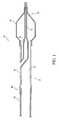
- FIG. 1is an illustration of a portion of a balloon catheter system, taken along a longitudinal cross section.
- FIG. 2Ais a perspective illustration of an inner section; and FIG. 2B is cross-sectional view of the inner section of the FIG. 2A , taken along line 2 B- 2 B.
- FIG. 3is an illustration, taken along a longitudinal cross section, of a tube passing through a die.
- FIG. 4is an illustration, taken along a longitudinal cross section, of a tube engaging with a die.
- FIGS. 5A and 5Bare longitudinal, cross-sectional views of tubes.
- the inventionfeatures medical devices having one or more portions that are rotated, e.g., circumferentially rotated.
- the portion(s)can be, for examples, portions of decreased or increased thickness and/or diameter, relative to other portion(s) of the medical device. Imparting a rotation to the portion(s) can enhance the kink or buckling resistance of the portion(s).
- a balloon catheter system 20includes a catheter shaft 22 and an expandable balloon 24 carried by the catheter shaft at a distal portion 26 .
- Catheter shaft 22is formed of a plurality of tubular components or sections bonded (e.g., welded) together. As shown, catheter shaft 22 includes a proximal outer section 28 , a distal outer section 30 bonded to the proximal outer section, and an inner section 32 bonded to the distal outer section. Proximal outer section 28 and distal outer section 30 define an inflation lumen 34 , and inner section 32 defines a guidewire lumen 36 .
- balloon catheter system 20can be delivered to a treatment site in the body by passing guidewire lumen 36 over a guidewire (not shown) emplaced in the body.
- balloon 24can be inflated or deflated by passing or withdrawing a fluid through inflation lumen 34 and into the interior of the balloon, e.g., to perform an angioplasty procedure or to deliver a stent.
- Examples of balloon cathetersare described, for example, in U.S. Pat. Nos. 6,702,781 and 6,488,694; and exemplified by the MonorailTM family of balloon catheters (Boston Scientific-SciMed, Maple Grove, Minn.).
- inner section 32includes a proximal portion 38 and a distal portion 40 having a wall thickness (T), an inner diameter (ID) and an outer diameter (OD) that are reduced relative to the thickness and diameters of proximal portion 38 .
- distal portion 40has a tapered region 41 and a region 43 having a substantially constant cross-sectional profile. Both tapered region 41 and region 43 have reduced wall thickness and diameters relative to those of proximal portion 38 .
- the reduced wall thickness and diameters of distal portion 40decrease the cross-sectional profile of inner section 32 , and decrease the cross-sectional profile of distal portion 26 of catheter system 20 . As a result, the flexibility of distal portion 26 is enhanced, which allows catheter system 20 to better navigate or track a tortuous path.
- the reduced cross-sectional profilealso allows catheter system 20 to access relatively narrow treatment sites.
- distal portion 40 of inner section 32is circumferentially rotated to enhance the compression strength of the distal portion.
- reducing the wall thickness and/or diameter(s) of inner section 32sometimes called “necking”, can reduce the radial strength of the inner section.
- neckingBy circumferentially rotating or twisting distal portion 40 such that the material of the distal portion has a degree of angular alignment, the compression strength and/or radial strength can be enhanced.
- distal portion 40 that has been circumferentially rotatedcan better resist compression and/or collapse, which can lead to kinking or buckling of the catheter system.
- the degree of circumferential rotationcan vary along a selected portion. For example, one segment of distal portion 40 can be more rotated than another segment of the distal portion. Increasing the degree of rotation of a segment can increase its compression strength and/or radial strength, but decrease its flexibility. The amount of rotation can range from about 2 turns/inch to about 20 turns/inch.
- the rotationcan be clockwise and/or counter-clockwise as viewed down the longitudinal axis. For example, one or more portions can be rotated clockwise, and one or more other portions can be rotated counterclockwise.
- Distal portion 40 of inner section 32can be formed by passing a tube through an appropriately configured die and realigning the tube.
- a tube 42 having generally the dimensions of proximal portion 38is inserted into a heatable die 44 having an appropriately configured cavity 46 , e.g., a conical or tapered cavity configured to form tapered region 41 .
- a mandrel 48is inserted into tube 42 to maintain the integrity of lumen 36 . Die 44 and/or mandrel 48 is heated to a temperature sufficient to soften the material of tube 42 so that the tube becomes pliable and can be rotated.
- tubes including PebaxTM polymerscan be heated to about 341° F.
- tubes including nyloncan be heated to about 330° F.
- tubes including polypropylenecan be heated to about 273-300° F.
- tubes including polyethylene (PE)can be heated to about 230° F. (low density PE) or about 260° F. (high density PE).
- tube 42As tube 42 is inserted into die 44 and contacts cavity 46 , the tube softens sufficiently so that its cross-sectional profile can be changed. As shown, the wall thickness, inner diameter and outer diameter of tube 42 is changed as the tube is passed through die 44 . After tube 42 is passed to a predetermined point, tube 42 is circumferentially rotated about the longitudinal axis of the tube (arrow R) to impart a degree of angular alignment to the material of the tube. Subsequently, tube 42 is retracted from die 44 and incorporated into catheter system 20 .
- die 44can be rotated.
- die 44can be rotated in a first direction, and tube 42 can be rotated in an opposite rotation.
- Die 44 and tube 42can be rotated in the same direction but at different speeds.
- die 44includes multiple heating zones, e.g., zones 50 , 52 , and 54 , that are individually controllable.
- one or more zonescan be heated at a higher temperature than one or more other zones to effect more softening.
- the portion(s) of tube 42 that are more heated, and thus, more softened,can be more easily rotated relative to less heated portion(s) to yield a tube with variable angular alignment.
- other heating sourcescan be used to heat tube 42 .
- tube 42can be heated using infrared radiation or a heat gun.
- circumferential rotationcan be applied to a member, such as a tubular member, having an increased inner diameter or an increased outer diameter.
- a membersuch as a tubular member, having an increased inner diameter or an increased outer diameter.
- the proximal portion 60 of distal outer section 30which is connected to proximal outer section 28 , is enlarged or flared relative to other portions of the distal outer section.
- Proximal portion 60can be circumferentially rotated or angularly aligned to enhance compression strength.
- the wall thickness of proximal portion 60can be less than or equal to the wall thickness relative to other portions of distal outer section 30 .
- Flaringcan be performed by inserting an appropriately shaped mandrel into a tube and realigning the tube.
- a tube 62 having generally the dimensions of distal outer section 30is passed over a heatable mandrel 64 .
- Mandrel 64has an elongated narrow portion 66 , a flared or tapered portion 68 , and a wide portion 70 .
- Narrow portion 66has an outer diameter substantially equal to the inner diameter of tube 62 to help maintain the integrity of the lumen of the tube.
- Mandrel 64is heated to a temperature sufficient to soften the material of tube 62 so that the tube can be rotated.
- FIG. 5Ashows a tube that can be formed if passed over flared portion 68
- FIG. 5Bshows a tube that can be formed if passed over flared portion 68 and wide portion 70 .
- mandrel 64with or without tube 62 , can be rotated.
- Mandrel 64can have multiple, individually controllable heating zones, e.g., flared portion 68 and the portion of wide portion 70 .
- Tube 62can be heated with other heat sources, such as infrared radiation.
- FIG. 1shows a particular type of balloon catheter system (sometimes called a “single operator exchange” balloon catheter), the circumferential rotation described herein can be applied to other balloon catheter systems.
- the balloon catheter systemcan be an angioplasty balloon, an over-the-wire balloon catheter system, a rapid exchange balloon catheter system (e.g., as described in U.S. Pat. No. 6,702,781), or a cutting balloon system (e.g., as described in U.S. Publication US-2003-0163148-A1).
- the tubes described aboveare incorporated into a balloon catheter, the tubes can be sized and shaped to be incorporated in a variety of catheters.
- cathetersinclude guide catheters (e.g., as described in U.S. Pat. No. 6,595,952), tumor ablation catheters, aneurysm catheters, urology catheters, and perfusion catheters (e.g., as described in U.S. Pat. No. 6,503,224).
- tubular segments of different compositionscan be necked and/or flared, and joined together at their ends, e.g., by an overlapping bond, to form a guidewire, a tube, or a cannula.
- the proximal segmentscan be relatively stiffer than the distal segments to provide good pushability and trackability.
- multiple tubular segmentscan be joined together to form an introducer sheath or a restraining sheath for a stent delivery system, for example, as described in U.S. Pat. No. 6,488,694; and Raeder-Devens et al., U.S. 2003/0050686.
- the methods described hereincan be used to manufacture a medical balloon.
- a first end of a ballooncan be inserted into heatable die 44 to impart angular alignment to the tapered regions, or cones, of the balloon, and/or to the sleeve portions of the balloon.
- the second end of the ballooncan be inserted into die 44 to impart angular alignment to the remaining tapered regions and/or sleeve portions.
- Die 44can be modified to extend over the body portion of the balloon to impart angular alignment to the body portion.
- the balloon wall in the body portioncan be relatively thin to other portions of the balloon because of the relatively large amount of stretching.
- angular alignmentcan be imparted to a tube, such as a co-extruded tube, and the tube can be formed into the medical balloon.
- a tubecan be prepared by an extrusion process.
- this processcan involve the use of an extrusion apparatus (e.g., a crosshead, such as a compact crosshead) having a series of discs.
- an extrusion apparatuse.g., a crosshead, such as a compact crosshead
- a suitable extrusion apparatusincluding some illustrative operating conditions, such as zone heating temperatures, polymer concentrations, feed rate, and line speed, are described in U.S. Ser. No. 09/798,749, entitled “Multilayer Medical Device” and filed on Mar. 2, 2001.
- one or more selected portions of the tube corresponding to portion(s) of the balloon where angular alignment is desiredis circumferentially rotated.
- the lumen of the tubecan be fitted with a supporting mandrel, and the selected portion(s) is heated and softened, e.g., by a heat gun.
- the tubecan then be rotated relative to the mandrel to impart angular alignment.
- the formed (e.g., co-extruded and rotated) tubecan be blow molded.
- the tubeis placed (e.g., centered) in a preheated balloon mold, and air is introduced into the tube to maintain the patency of the tube lumen.
- the tubeis stretched for a predetermined distance at a predetermined time, rate, and temperature.
- the pressure inside the tubeis then sufficiently increased to radially expand the tube inside the mold to form the balloon.
- the formed ballooncan be heat treated, for example, to enhance folding memory, and/or folded into a predetermined profile.
- the components, such as tube 42 , of the medical devices described abovecan include, for example, thermoplastics and thermosets.
- thermoplasticsinclude polyolefins, polyamides, such as nylon 12, nylon 11, nylon 6/12, nylon 6, and nylon 66, polyesters (such as polyterephthalate (PET)), polyethers, polyurethanes, polyvinyls, polyacrylics, fluoropolymers, copolymers and block copolymers thereof, such as block copolymers of polyether and polyamide, e.g., Pebax®; and mixtures thereof.
- PETpolyterephthalate
- thermosetsexamples include elastomers such as EPDM, epichlorohydrin, polyureas, nitrile butadiene elastomers, silicones, etc.
- Thermosetssuch as epoxies and isocyanates, can also be used.
- Biocompatible thermosetsmay also be used, and these include, for example, biodegradable polycaprolactone, poly(dimethylsiloxane) containing polyurethanes and ureas, and polysiloxanes.
- Other polymersare described in commonly assigned U.S. Ser. No. 10/645,055, filed Aug. 21, 2003.
- a componentcan include one or more polymers.
- the componentscan include a nanocomposite, as described in U.S. Patent Application Publication 2003/0093107.
- the tubes and balloons described hereincan include a plurality of layers, such as multiple coextruded layers. One or more layers can vary in thickness along the length of the tube or balloon. Multilayer tubes and balloons are described, for example, in commonly assigned U.S. Ser. No. 10/645,014, filed Aug. 21, 2003; and U.S. Ser. No. 10/645,055, filed Aug. 21, 2003.
- the tubes and balloons described hereincan include one or more longitudinal stripes of a strengthening material, such as a liquid crystalline polymer. Medical components having longitudinal stripes are described in commonly assigned U.S. Patent Application Publication US-2003-0163148-A1.
- the components, such as tube 42 , of the medical devices described abovecan include a non-polymer, such as a metal.
- a metal tubecan be heated to its softening point and circumferentially rotated as described herein.
- metalsinclude stainless steel, gold, platinum, alloys containing molybdenum, alloys containing titanium (such as Nitinol), and alloys containing cobalt.
Landscapes
- Health & Medical Sciences (AREA)
- Life Sciences & Earth Sciences (AREA)
- Heart & Thoracic Surgery (AREA)
- Engineering & Computer Science (AREA)
- Biomedical Technology (AREA)
- Pulmonology (AREA)
- Biophysics (AREA)
- Anesthesiology (AREA)
- Hematology (AREA)
- Animal Behavior & Ethology (AREA)
- General Health & Medical Sciences (AREA)
- Public Health (AREA)
- Veterinary Medicine (AREA)
- Child & Adolescent Psychology (AREA)
- Manufacturing & Machinery (AREA)
- Media Introduction/Drainage Providing Device (AREA)
- Materials For Medical Uses (AREA)
Abstract
Description
Claims (17)
Priority Applications (1)
| Application Number | Priority Date | Filing Date | Title |
|---|---|---|---|
| US10/838,540US8353867B2 (en) | 2004-05-04 | 2004-05-04 | Medical devices |
Applications Claiming Priority (1)
| Application Number | Priority Date | Filing Date | Title |
|---|---|---|---|
| US10/838,540US8353867B2 (en) | 2004-05-04 | 2004-05-04 | Medical devices |
Publications (2)
| Publication Number | Publication Date |
|---|---|
| US20050251107A1 US20050251107A1 (en) | 2005-11-10 |
| US8353867B2true US8353867B2 (en) | 2013-01-15 |
Family
ID=35240357
Family Applications (1)
| Application Number | Title | Priority Date | Filing Date |
|---|---|---|---|
| US10/838,540Active2028-12-06US8353867B2 (en) | 2004-05-04 | 2004-05-04 | Medical devices |
Country Status (1)
| Country | Link |
|---|---|
| US (1) | US8353867B2 (en) |
Cited By (3)
| Publication number | Priority date | Publication date | Assignee | Title |
|---|---|---|---|---|
| US20140250661A1 (en)* | 2007-06-01 | 2014-09-11 | Covidien Lp | Extension tubes for balloon catheters |
| US10363399B2 (en) | 2014-09-30 | 2019-07-30 | Boston Scientific Scimed, Inc. | Dual-layer balloon design and method of making the same |
| US11123519B2 (en) | 2016-12-21 | 2021-09-21 | Biosense Webster (Israel) Ltd. | Layered tube for improved kink resistance |
Families Citing this family (5)
| Publication number | Priority date | Publication date | Assignee | Title |
|---|---|---|---|---|
| US8500797B2 (en)* | 2004-09-08 | 2013-08-06 | Boston Scientific Scimed, Inc. | Medical devices |
| US20060229657A1 (en)* | 2005-03-30 | 2006-10-12 | Wasicek Lawrence D | Single operator exchange embolic protection filter |
| JP2009519770A (en) | 2005-12-16 | 2009-05-21 | インターフェイス・アソシエイツ・インコーポレーテッド | Medical multilayer balloon and method for producing the same |
| EP2659034B1 (en) | 2010-12-29 | 2019-02-20 | University of Pittsburgh - Of the Commonwealth System of Higher Education | System and method for mandrel-less electrospinning |
| ES2864000T3 (en)* | 2014-10-02 | 2021-10-13 | Aachen Scient International Pte Ltd | Procedure for trimming intravascular dilatation catheters |
Citations (34)
| Publication number | Priority date | Publication date | Assignee | Title |
|---|---|---|---|---|
| US3752617A (en) | 1969-10-13 | 1973-08-14 | Sherwood Medical Ind Inc | Apparatus for extruding products of plural components of varied proportions with scrap reclamation |
| US4795439A (en)* | 1986-06-06 | 1989-01-03 | Edward Weck Incorporated | Spiral multi-lumen catheter |
| US4963313A (en) | 1987-11-30 | 1990-10-16 | Boston Scientific Corporation | Balloon catheter |
| US5195969A (en) | 1991-04-26 | 1993-03-23 | Boston Scientific Corporation | Co-extruded medical balloons and catheter using such balloons |
| US5248305A (en) | 1989-08-04 | 1993-09-28 | Cordis Corporation | Extruded tubing and catheters having helical liquid crystal fibrils |
| US5270086A (en) | 1989-09-25 | 1993-12-14 | Schneider (Usa) Inc. | Multilayer extrusion of angioplasty balloons |
| US5525388A (en) | 1992-08-07 | 1996-06-11 | Advanced Cardiovascular Systems, Inc. | Dilatation balloon with constant wall thickness |
| US5614136A (en)* | 1995-03-02 | 1997-03-25 | Scimed Life Systems, Inc. | Process to form dimensionally variable tubular members for use in catheter procedures |
| US5639409A (en) | 1994-01-07 | 1997-06-17 | Cordis Corporation | Method for manufacturing a tubular extrusion |
| US5714110A (en) | 1993-09-20 | 1998-02-03 | Scimed Life Systems, Inc. | Process improvements for preparing catheter balloons |
| US5725814A (en) | 1995-06-07 | 1998-03-10 | Harrel, Inc. | Extrusion of an article of varying content |
| US5807520A (en) | 1995-11-08 | 1998-09-15 | Scimed Life Systems, Inc. | Method of balloon formation by cold drawing/necking |
| US5820594A (en) | 1994-01-31 | 1998-10-13 | Cordis Corporation | Balloon catheter |
| US6027477A (en) | 1993-10-27 | 2000-02-22 | Schneider (Europe) A.G. | Catheter with multilayer tube |
| US6030405A (en) | 1997-04-28 | 2000-02-29 | Medtronic Inc. | Dilatation catheter with varied stiffness |
| US6045547A (en) | 1998-06-15 | 2000-04-04 | Scimed Life Systems, Inc. | Semi-continuous co-extruded catheter shaft |
| US6120364A (en) | 1998-07-06 | 2000-09-19 | Laflamme; Robert | Grinding fixture and assembly |
| US6193738B1 (en) | 1998-05-11 | 2001-02-27 | Scimed Life Systems, Inc. | Balloon cones and waists thinning methodology |
| WO2001032398A1 (en) | 1999-10-29 | 2001-05-10 | Boston Scientific Limited | Method and apparatus for extruding catheter tubing |
| US6319228B1 (en) | 1996-04-26 | 2001-11-20 | Schneider (Europe) A.G. | Multilayer interventional catheter |
| US6464683B1 (en) | 1997-04-25 | 2002-10-15 | Schneider (Usa) Inc. | Trilayer, extruded medical tubing and medical devices incorporating such tubbing |
| US6471673B1 (en) | 1993-10-27 | 2002-10-29 | Schneider (Europe) A.G. | Catheter with multilayer tube |
| US20020165523A1 (en) | 2000-03-02 | 2002-11-07 | Chin Albert C. C. | Multilayer medical device |
| US6488694B1 (en) | 1991-01-28 | 2002-12-03 | Advanced Cardiovascular Systems, Inc. | Stent delivery system |
| US6503224B1 (en) | 1997-06-12 | 2003-01-07 | Scimed Life Systems, Inc. | Perfusion balloon catheter |
| US20030050686A1 (en) | 1999-05-14 | 2003-03-13 | Raeder-Devens Jennifer E. | Prosthesis deployment device with translucent distal end |
| US20030065355A1 (en) | 2001-09-28 | 2003-04-03 | Jan Weber | Medical devices comprising nonomaterials and therapeutic methods utilizing the same |
| US6554841B1 (en) | 2000-09-22 | 2003-04-29 | Scimed Life Systems, Inc. | Striped sleeve for stent delivery |
| US6595952B2 (en) | 2001-01-04 | 2003-07-22 | Scimed Life Systems, Inc. | Guide catheter with backup support system |
| US20030163148A1 (en) | 2002-02-27 | 2003-08-28 | Lixiao Wang | Medical device |
| US6663614B1 (en)* | 2000-11-06 | 2003-12-16 | Advanced Cardiovascular Systems, Inc. | Catheter shaft having variable thickness layers and method of making |
| US6702781B1 (en) | 1991-04-05 | 2004-03-09 | Boston Scientific Technology, Inc. | Adjustably stiffenable convertible catheter assembly |
| US20040073250A1 (en) | 2002-10-15 | 2004-04-15 | Pederson Gary John | Catheter balloon with advantageous cone design |
| US7128862B2 (en) | 2001-07-03 | 2006-10-31 | Scimed Life Systems, Inc. | Biaxially oriented multilayer polymer tube for medical devices |
Family Cites Families (1)
| Publication number | Priority date | Publication date | Assignee | Title |
|---|---|---|---|---|
| WO2001079891A1 (en)* | 2000-04-13 | 2001-10-25 | Frank Andreasen | Probe for detecting the structure of a dielectric medium |
- 2004
- 2004-05-04USUS10/838,540patent/US8353867B2/enactiveActive
Patent Citations (37)
| Publication number | Priority date | Publication date | Assignee | Title |
|---|---|---|---|---|
| US3752617A (en) | 1969-10-13 | 1973-08-14 | Sherwood Medical Ind Inc | Apparatus for extruding products of plural components of varied proportions with scrap reclamation |
| US4795439A (en)* | 1986-06-06 | 1989-01-03 | Edward Weck Incorporated | Spiral multi-lumen catheter |
| US4963313A (en) | 1987-11-30 | 1990-10-16 | Boston Scientific Corporation | Balloon catheter |
| US5248305A (en) | 1989-08-04 | 1993-09-28 | Cordis Corporation | Extruded tubing and catheters having helical liquid crystal fibrils |
| US5270086A (en) | 1989-09-25 | 1993-12-14 | Schneider (Usa) Inc. | Multilayer extrusion of angioplasty balloons |
| US6488694B1 (en) | 1991-01-28 | 2002-12-03 | Advanced Cardiovascular Systems, Inc. | Stent delivery system |
| US6702781B1 (en) | 1991-04-05 | 2004-03-09 | Boston Scientific Technology, Inc. | Adjustably stiffenable convertible catheter assembly |
| US6136258A (en) | 1991-04-26 | 2000-10-24 | Boston Scientific Corporation | Method of forming a co-extruded balloon for medical purposes |
| US5195969A (en) | 1991-04-26 | 1993-03-23 | Boston Scientific Corporation | Co-extruded medical balloons and catheter using such balloons |
| US5525388A (en) | 1992-08-07 | 1996-06-11 | Advanced Cardiovascular Systems, Inc. | Dilatation balloon with constant wall thickness |
| US5714110A (en) | 1993-09-20 | 1998-02-03 | Scimed Life Systems, Inc. | Process improvements for preparing catheter balloons |
| US6027477A (en) | 1993-10-27 | 2000-02-22 | Schneider (Europe) A.G. | Catheter with multilayer tube |
| US6471673B1 (en) | 1993-10-27 | 2002-10-29 | Schneider (Europe) A.G. | Catheter with multilayer tube |
| US5639409A (en) | 1994-01-07 | 1997-06-17 | Cordis Corporation | Method for manufacturing a tubular extrusion |
| US5820594A (en) | 1994-01-31 | 1998-10-13 | Cordis Corporation | Balloon catheter |
| US5824173A (en) | 1994-01-31 | 1998-10-20 | Cordis Corporation | Method for making a balloon catheter |
| US5614136A (en)* | 1995-03-02 | 1997-03-25 | Scimed Life Systems, Inc. | Process to form dimensionally variable tubular members for use in catheter procedures |
| US5725814A (en) | 1995-06-07 | 1998-03-10 | Harrel, Inc. | Extrusion of an article of varying content |
| US5807520A (en) | 1995-11-08 | 1998-09-15 | Scimed Life Systems, Inc. | Method of balloon formation by cold drawing/necking |
| US6319228B1 (en) | 1996-04-26 | 2001-11-20 | Schneider (Europe) A.G. | Multilayer interventional catheter |
| US6464683B1 (en) | 1997-04-25 | 2002-10-15 | Schneider (Usa) Inc. | Trilayer, extruded medical tubing and medical devices incorporating such tubbing |
| US6030405A (en) | 1997-04-28 | 2000-02-29 | Medtronic Inc. | Dilatation catheter with varied stiffness |
| US6503224B1 (en) | 1997-06-12 | 2003-01-07 | Scimed Life Systems, Inc. | Perfusion balloon catheter |
| US6193738B1 (en) | 1998-05-11 | 2001-02-27 | Scimed Life Systems, Inc. | Balloon cones and waists thinning methodology |
| US6045547A (en) | 1998-06-15 | 2000-04-04 | Scimed Life Systems, Inc. | Semi-continuous co-extruded catheter shaft |
| US6120364A (en) | 1998-07-06 | 2000-09-19 | Laflamme; Robert | Grinding fixture and assembly |
| US20030050686A1 (en) | 1999-05-14 | 2003-03-13 | Raeder-Devens Jennifer E. | Prosthesis deployment device with translucent distal end |
| WO2001032398A1 (en) | 1999-10-29 | 2001-05-10 | Boston Scientific Limited | Method and apparatus for extruding catheter tubing |
| US20020165523A1 (en) | 2000-03-02 | 2002-11-07 | Chin Albert C. C. | Multilayer medical device |
| US6554841B1 (en) | 2000-09-22 | 2003-04-29 | Scimed Life Systems, Inc. | Striped sleeve for stent delivery |
| US6663614B1 (en)* | 2000-11-06 | 2003-12-16 | Advanced Cardiovascular Systems, Inc. | Catheter shaft having variable thickness layers and method of making |
| US6595952B2 (en) | 2001-01-04 | 2003-07-22 | Scimed Life Systems, Inc. | Guide catheter with backup support system |
| US7128862B2 (en) | 2001-07-03 | 2006-10-31 | Scimed Life Systems, Inc. | Biaxially oriented multilayer polymer tube for medical devices |
| US20030065355A1 (en) | 2001-09-28 | 2003-04-03 | Jan Weber | Medical devices comprising nonomaterials and therapeutic methods utilizing the same |
| US20030093107A1 (en) | 2001-09-28 | 2003-05-15 | Edward Parsonage | Medical devices comprising nanocomposites |
| US20030163148A1 (en) | 2002-02-27 | 2003-08-28 | Lixiao Wang | Medical device |
| US20040073250A1 (en) | 2002-10-15 | 2004-04-15 | Pederson Gary John | Catheter balloon with advantageous cone design |
Non-Patent Citations (3)
| Title |
|---|
| U.S. Appl. No. 10/263,225, filed Oct. 2, 2002. |
| U.S. Appl. No. 10/645,014, filed Aug. 31, 2003. |
| U.S. Appl. No. 10/645,055, filed Aug. 31, 2003. |
Cited By (4)
| Publication number | Priority date | Publication date | Assignee | Title |
|---|---|---|---|---|
| US20140250661A1 (en)* | 2007-06-01 | 2014-09-11 | Covidien Lp | Extension tubes for balloon catheters |
| US9861798B2 (en)* | 2007-06-01 | 2018-01-09 | Covidien Lp | Extension tubes for balloon catheters |
| US10363399B2 (en) | 2014-09-30 | 2019-07-30 | Boston Scientific Scimed, Inc. | Dual-layer balloon design and method of making the same |
| US11123519B2 (en) | 2016-12-21 | 2021-09-21 | Biosense Webster (Israel) Ltd. | Layered tube for improved kink resistance |
Also Published As
| Publication number | Publication date |
|---|---|
| US20050251107A1 (en) | 2005-11-10 |
Similar Documents
| Publication | Publication Date | Title |
|---|---|---|
| US6989025B2 (en) | Extruded tubing with discontinuous striping | |
| US8088121B2 (en) | Catheter | |
| US7273485B2 (en) | Balloon catheter having a shaft with a variable stiffness inner tubular member | |
| EP2474336B1 (en) | Balloon catheter shaft having high strength and flexibility and method of making same | |
| EP0773802B1 (en) | Intraluminal catheter with high strength proximal shaft | |
| US7166100B2 (en) | Balloon catheter shaft design | |
| US7906066B2 (en) | Method of making a balloon catheter shaft having high strength and flexibility | |
| JP6234923B2 (en) | Medical tube for catheter | |
| EP2895226B1 (en) | Method of manufacturing a soft tip balloon catheter | |
| US6443925B1 (en) | Balloon catheter shaft formed of liquid crystal polymeric material blend | |
| US6589226B1 (en) | Catheter shaft and method of making a catheter shaft | |
| US20090254113A1 (en) | Dilatation balloon with ridges and methods | |
| WO2014144467A1 (en) | Reduced material tip for catheter and method of forming same | |
| JP5537934B2 (en) | Medical devices and related systems and methods | |
| US8353867B2 (en) | Medical devices | |
| JP2008110132A (en) | Catheter | |
| US7118551B1 (en) | Non-metal reinforcing mandrel | |
| JP4833039B2 (en) | catheter | |
| JP4914282B2 (en) | Catheter with pushability | |
| US8241246B2 (en) | Side by side lumen catheter and method of manufacture thereof |
Legal Events
| Date | Code | Title | Description |
|---|---|---|---|
| AS | Assignment | Owner name:SCIMED LIFE SYSTEMS, INC., MINNESOTA Free format text:ASSIGNMENT OF ASSIGNORS INTEREST;ASSIGNOR:OLSON, GREG;REEL/FRAME:015036/0023 Effective date:20040429 | |
| AS | Assignment | Owner name:BOSTON SCIENTIFIC SCIMED, INC., MINNESOTA Free format text:CHANGE OF NAME;ASSIGNOR:SCIMED LIFE SYSTEMS, INC.;REEL/FRAME:018505/0868 Effective date:20050101 Owner name:BOSTON SCIENTIFIC SCIMED, INC.,MINNESOTA Free format text:CHANGE OF NAME;ASSIGNOR:SCIMED LIFE SYSTEMS, INC.;REEL/FRAME:018505/0868 Effective date:20050101 | |
| STCF | Information on status: patent grant | Free format text:PATENTED CASE | |
| FPAY | Fee payment | Year of fee payment:4 | |
| MAFP | Maintenance fee payment | Free format text:PAYMENT OF MAINTENANCE FEE, 8TH YEAR, LARGE ENTITY (ORIGINAL EVENT CODE: M1552); ENTITY STATUS OF PATENT OWNER: LARGE ENTITY Year of fee payment:8 | |
| MAFP | Maintenance fee payment | Free format text:PAYMENT OF MAINTENANCE FEE, 12TH YEAR, LARGE ENTITY (ORIGINAL EVENT CODE: M1553); ENTITY STATUS OF PATENT OWNER: LARGE ENTITY Year of fee payment:12 |