US8353703B2 - Healing components for use in taking impressions and methods for making the same - Google Patents
Healing components for use in taking impressions and methods for making the sameDownload PDFInfo
- Publication number
- US8353703B2 US8353703B2US13/163,292US201113163292AUS8353703B2US 8353703 B2US8353703 B2US 8353703B2US 201113163292 AUS201113163292 AUS 201113163292AUS 8353703 B2US8353703 B2US 8353703B2
- Authority
- US
- United States
- Prior art keywords
- dental implant
- attachment member
- abutment
- mouth
- custom
- Prior art date
- Legal status (The legal status is an assumption and is not a legal conclusion. Google has not performed a legal analysis and makes no representation as to the accuracy of the status listed.)
- Expired - Fee Related
Links
Images


Classifications
- A—HUMAN NECESSITIES
- A61—MEDICAL OR VETERINARY SCIENCE; HYGIENE
- A61C—DENTISTRY; APPARATUS OR METHODS FOR ORAL OR DENTAL HYGIENE
- A61C8/00—Means to be fixed to the jaw-bone for consolidating natural teeth or for fixing dental prostheses thereon; Dental implants; Implanting tools
- A—HUMAN NECESSITIES
- A61—MEDICAL OR VETERINARY SCIENCE; HYGIENE
- A61B—DIAGNOSIS; SURGERY; IDENTIFICATION
- A61B1/00—Instruments for performing medical examinations of the interior of cavities or tubes of the body by visual or photographical inspection, e.g. endoscopes; Illuminating arrangements therefor
- A61B1/24—Instruments for performing medical examinations of the interior of cavities or tubes of the body by visual or photographical inspection, e.g. endoscopes; Illuminating arrangements therefor for the mouth, i.e. stomatoscopes, e.g. with tongue depressors; Instruments for opening or keeping open the mouth
- A—HUMAN NECESSITIES
- A61—MEDICAL OR VETERINARY SCIENCE; HYGIENE
- A61C—DENTISTRY; APPARATUS OR METHODS FOR ORAL OR DENTAL HYGIENE
- A61C13/00—Dental prostheses; Making same
- A61C13/0003—Making bridge-work, inlays, implants or the like
- A61C13/0004—Computer-assisted sizing or machining of dental prostheses
- A—HUMAN NECESSITIES
- A61—MEDICAL OR VETERINARY SCIENCE; HYGIENE
- A61C—DENTISTRY; APPARATUS OR METHODS FOR ORAL OR DENTAL HYGIENE
- A61C13/00—Dental prostheses; Making same
- A61C13/08—Artificial teeth; Making same
- A—HUMAN NECESSITIES
- A61—MEDICAL OR VETERINARY SCIENCE; HYGIENE
- A61C—DENTISTRY; APPARATUS OR METHODS FOR ORAL OR DENTAL HYGIENE
- A61C13/00—Dental prostheses; Making same
- A61C13/08—Artificial teeth; Making same
- A61C13/083—Porcelain or ceramic teeth
- A—HUMAN NECESSITIES
- A61—MEDICAL OR VETERINARY SCIENCE; HYGIENE
- A61C—DENTISTRY; APPARATUS OR METHODS FOR ORAL OR DENTAL HYGIENE
- A61C8/00—Means to be fixed to the jaw-bone for consolidating natural teeth or for fixing dental prostheses thereon; Dental implants; Implanting tools
- A61C8/0001—Impression means for implants, e.g. impression coping
- A—HUMAN NECESSITIES
- A61—MEDICAL OR VETERINARY SCIENCE; HYGIENE
- A61C—DENTISTRY; APPARATUS OR METHODS FOR ORAL OR DENTAL HYGIENE
- A61C8/00—Means to be fixed to the jaw-bone for consolidating natural teeth or for fixing dental prostheses thereon; Dental implants; Implanting tools
- A61C8/0048—Connecting the upper structure to the implant, e.g. bridging bars
- A61C8/005—Connecting devices for joining an upper structure with an implant member, e.g. spacers
- A—HUMAN NECESSITIES
- A61—MEDICAL OR VETERINARY SCIENCE; HYGIENE
- A61C—DENTISTRY; APPARATUS OR METHODS FOR ORAL OR DENTAL HYGIENE
- A61C8/00—Means to be fixed to the jaw-bone for consolidating natural teeth or for fixing dental prostheses thereon; Dental implants; Implanting tools
- A61C8/008—Healing caps or the like
- A—HUMAN NECESSITIES
- A61—MEDICAL OR VETERINARY SCIENCE; HYGIENE
- A61C—DENTISTRY; APPARATUS OR METHODS FOR ORAL OR DENTAL HYGIENE
- A61C9/00—Impression cups, i.e. impression trays; Impression methods
- A61C9/004—Means or methods for taking digitized impressions
- A—HUMAN NECESSITIES
- A61—MEDICAL OR VETERINARY SCIENCE; HYGIENE
- A61C—DENTISTRY; APPARATUS OR METHODS FOR ORAL OR DENTAL HYGIENE
- A61C9/00—Impression cups, i.e. impression trays; Impression methods
- A61C9/004—Means or methods for taking digitized impressions
- A61C9/0046—Data acquisition means or methods
- A61C9/0053—Optical means or methods, e.g. scanning the teeth by a laser or light beam
- G—PHYSICS
- G06—COMPUTING OR CALCULATING; COUNTING
- G06F—ELECTRIC DIGITAL DATA PROCESSING
- G06F30/00—Computer-aided design [CAD]
Definitions
- the present inventionrelates generally to a healing abutment in a dental implant system. More particularly, the present invention relates to the use of a binary marking system on the exterior of a healing abutment to identify unique characteristics of the healing abutment.
- the dental restoration of a partially or wholly edentulous patient with artificial dentitionis typically done in two stages.
- an incisionis made through the gingiva to expose the underlying bone.
- An artificial tooth rootusually a dental implant, is placed in the jawbone for integration.
- the dental implantgenerally includes a threaded bore to receive a retaining screw holding mating components therein.
- the gum tissue overlying the implantis sutured and heals as the osseointegration process continues.
- the second stageis initiated.
- the gum tissueis re-opened to expose the end of the dental implant.
- a healing component or healing abutmentis fastened to the exposed end of the dental implant to allow the gum tissue to heal therearound.
- the gum tissueheals such that the aperture that remains generally approximates the size and contour of the aperture that existed around the natural tooth that is being replaced.
- the healing abutment attached to the exposed end of the dental implanthas the same general contour as the gingival portion of the natural tooth being replaced. It should be noted that the healing abutment can be placed on the implant immediately after the implant has been installed and before osseointegration.
- the healing abutmentis removed and an impression coping is fitted onto the exposed end of the implant.
- the healing component and the impression copingare two physically separate components.
- the impression copinghas the same gingival dimensions as the healing component so that there is no gap between the impression coping and the wall of the gum tissue defining the aperture. Otherwise, a less than accurate impression of the condition of the patient's mouth is taken.
- the impression copingmay be a “pick-up”-type impression coping or a “transfer”-type impression coping, both known in the art.
- a scanning devicecan scan the region in the patient's mouth where the prosthesis is to be placed without the need to use impression materials or to construct a mold.
- a scanning devicecan scan the region in the patient's mouth where the prosthesis is to be placed without the need to use impression materials or to construct a mold.
- the impression material that is removed from the healing abutment and the surrounding areais scanned to produce the permanent components.
- a dentistcan scan the stone model of the dental region that was formed from the impression material or scan the stone model.
- Each scanning techniqueis used or modified for any of the above-listed approaches (a scan of the stone model, a scan of the impression material, or a scan in the mouth without using impression material) to create the prosthesis.
- a laboratorycan create and manufacture the permanent crown or bridge, usually using a computer-aided design (“CAD”) package.
- CADcomputer-aided design
- a CAD programas disclosed in U.S. Pat. No. 5,338,198 (Wu), whose disclosure is incorporated herein by reference, is one method of scanning a dental region to create a three-dimensional model.
- the impression material or stone modelis placed on a support table defining the X-Y plane.
- a scanning laser light probeis directed onto the model.
- the laser light probeemits a pulse of laser light that is reflected by the model.
- a detectorreceives light scattered from the impact of the beam with the impression to calculate a Z-axis measurement.
- the model and the beamare relatively translated within the X-Y plane to gather a plurality of contact points with known locations in the X-Y coordinate plane.
- the locations of several contact points in the Z-planeare determined by detecting reflected light. Finally, correlating data of the X-Y coordinates and the Z-direction contact points creates a digital image.
- the modelmay be tilted to raise one side of the mold relative to the opposite vertically away from the X-Y plane. Subsequent to the model's second scan, the model may be further rotated to allow for a more accurate reading of the model. After all scans are complete, the data may be fed into a CAD system for manipulation of this electronic data by known means.
- Photographic imagingcan also be used to scan impression material, a stone model, or directly in the mouth.
- one systemtakes photographs at multiple angles in one exposure to scan a dental region, create a model, and manufacture a prosthetic tooth.
- this processis generally initiated with the process of taking a stereophotograph with a camera from approximately 50 to 150 mm away from the patient's mouth.
- the stereophotographcan involve a photograph of a patient's mouth already prepared with implantation devices. Correct spatial positioning of the dental implants is obtained by marking the implant in several locations. The resulting photograph presents multiple images of the same object.
- the images on the photographsare scanned with a reading device that digitizes the photographs to produce a digital image of the dental region.
- the data from the scanneris electronically transmitted to a graphical imaging program that creates a model that is displayed to the user. After identification of the shape, position, and other details of the model, the ultimate step is the transmission of the data to a computer for manufacturing.
- a third scanning measureuses mechanical sensing.
- a mechanical contour sensing deviceas disclosed in U.S. Pat. No. 5,652,709 (Andersson), whose disclosure is incorporated herein by reference, is another method used to read a dental model and produce a prosthetic tooth.
- the impression modelis secured to a table that may rotate about its longitudinal axis as well as translate along the same axis with variable speeds.
- a mechanical sensing unitis placed in contact with the model at a known angle and the sensing equipment is held firmly against the surface of the model by a spring.
- the sensing equipmentcan measure the changes in the contour and create an electronic representation of the data.
- a computerthen processes the electronic representation and the data from the scanning device to create a data array. The computer further compresses the data for storage and/or transmission to the milling equipment.
- the present inventionis a healing abutment having a plurality of external marking locations where markers are either present or absent. Due to the presence or absence of the markers, the physical characteristics of the healing abutment are identifiable through use of a binary-coded system.
- the present inventioncontemplates providing a set of healing abutments, each of which has unique physical characteristics and a unique binary marking code that indicates those unique physical characteristics.
- a healing abutmentis non-rotationally fastened to the implant through complimentary non-round fittings on the implant and abutment, which usually take the form of a hexagonal boss and socket.
- the healing abutmentis held on the implant via a screw that engages the threaded bore of the implant.
- the presence or absence of the markers in the marking locationsmay eliminate the need for an impression coping within the implant system.
- An impressioncan be taken of the mouth with the markers creating features in the impression material.
- the impression or a model of the impressionis read or scanned such that the markers indicate various characteristics of the healing abutment and also the implant. Further, such a system eliminates the need to remove the healing abutment until the permanent components are ready to be installed in the patient's mouth.
- the presence or absence of the binary-coded markers in the marking locationsallow the dentist to determine various physical characteristics, such as the healing abutment height, healing abutment diameter, dimensions of the attached implant seating surface, and the orientation of the implant's fitting. It is contemplated in accordance with one embodiment of the present invention that these marking locations containing the binary-coded markers are preferably located on the top of the healing abutment, although it may be possible to place some markers on the side of the healing abutment.
- the information markerscorrespond to the height of the abutment to be captured in an impression or subsequent scan.
- a 6 mm tall healing abutmentmay possess six information markers on the top or side surface of the healing abutment.
- a 4 mm tall healing abutmentmay possess four information markers, and a 2 mm tall healing abutment may possess two information markers.
- This marking systemmay be altered to decrease the quantity of information markers required on the top or side surface of the healing abutment.
- the use of three information markers on the top or side surfacemay represent a 6 mm tall healing abutment, two information markers may represent a 4 mm tall healing abutment, and one marker may represent a 2 mm tall healing abutment.
- the healing abutments of the present inventioncan be manufactured in sets of healing abutments, each set having healing abutments of the same diameter but different healing abutment heights. Different sets of healing abutments would have healing abutments with different diameters.
- a first set of healing abutmentsmay contain three healing abutments, one abutment of 2 mm, 4 mm, and 6 mm height, respectively, and each with a diameter of 4 mm.
- a second set of healing abutmentsmay also have abutments with heights of 2 mm, 4 mm, and 6 mm, but these abutments may have a diameter of 5 mm.
- Information markers at one or more marking locationsdistinguish not only between the first and second set of healing abutments, but also between the three healing abutments within each set.
- An impression of the mouthis taken with the inventive healing abutment mounted on the implant.
- the impression processcreates a “negative” image of the information markers in the impression material that change the physical shape of the top or side surface.
- a corresponding moldis created from the impression.
- This mold, or a stone model created from the moldcan then be scanned.
- a computer programis able to create a three-dimensional perspective of the relevant jaw section of the patient, including the implant and abutment. Due to the information markers on the surface of the healing abutment now present in the mold, the computer program is able to accurately analyze and produce the appropriate dimensions of the aperture in the gingiva and the orientation of the underlying hexagonal boss of the implant so that a clinician can instruct a milling machine to produce the permanent components.
- the scannersimply takes the necessary information directly from the mouth of a patient without the need for impression material whatsoever.
- the information markers of the healing abutmentprovide the required information of the gingival aperture and the orientation of the underlying hexagonal boss on the implant. If a laser or photographic scanning system is used, the etched markers are identified just as easily as the markers that change the physical shape of the healing abutment.
- This systemallows the dentist to produce the permanent components more quickly because the healing abutment does not have to be removed in order to produce the permanent dental components.
- the second step of taking an impression with an impression copingis eliminated.
- the dentistalso does not have to confront the difficulties of gingival closure that appear when a healing implant is removed.
- the patientis not forced to endure the somewhat painful procedure of healing abutment removal. With the procedure of the present invention, the removal of the healing abutment can occur during the same surgery as the installation of the permanent components.
- an impression copingmay possess information markers as described above and replace the standard healing abutment during second stage dental restoration surgery.
- the impression coping and surrounding environmentare scanned directly in the mouth.
- An impressioncould also be formed and a stone model produced from the impression. This stone model is scanned to create the permanent prosthesis using one of the scanning techniques described above.
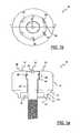
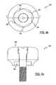
- FIG. 1 ais a top view of a healing abutment.
- FIG. 1 bis a longitudinal cross-sectional view of the healing abutment shown in FIG. 1 a.
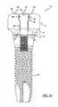
- FIG. 1 cis the healing abutment shown in FIG. 1 b attached to an implant.
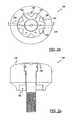
- FIG. 2 ais a top view of another embodiment of a healing abutment.
- FIG. 2 bis a longitudinal cross-sectional view of the healing abutment shown in FIG. 2 a.
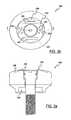
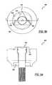
- FIG. 3 ais a top view of yet another embodiment of a healing abutment.
- FIG. 3 bis a longitudinal cross-sectional view of the healing abutment shown in FIG. 3 a.
- FIG. 4 ais a top view of a further embodiment of the healing abutment.
- FIG. 4 bis a longitudinal cross-sectional view of the healing abutment shown in FIG. 4 a.
- FIG. 5 ais a top view of another embodiment of a healing abutment.
- FIG. 5 bis a longitudinal cross-sectional view of the healing abutment shown in FIG. 5 a.
- FIG. 6 ais a top view of another embodiment of a healing abutment.
- FIG. 6 bis a longitudinal cross-sectional view of the healing abutment shown in FIG. 6 a.
- FIG. 7is an exploded view of another embodiment of the present application.
- FIG. 8is a side view of a method for stereophotographic imaging.
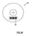
- FIGS. 9 a - 9 pare top views of a plurality of healing abutments having a binary-type system of information markers.
- FIG. 9 qis a top view of a healing abutment having a bar code information marker.
- FIG. 10is a perspective view of a coordinate system of one embodiment of the present invention.
- the healing abutment 10 of one embodiment of the present inventionhas a main body 15 with a generally circular cross-sectional shape, a first tapered section 17 , a boundary 19 , a second tapered section 21 , an end surface 23 , a hex socket 25 , and dimensions that are generally suitable for replicating the emergence profile of a natural tooth.
- the first tapered section 17extends downward from the main body 15 of the abutment 10 , having a diameter at a boundary 19 that is generally larger than the implant (not shown).
- the boundary 19separates the first tapered section 17 from the second tapered section 21 that terminates in the end surface 23 .
- the second tapered section 21is at an angle with the central axis of the implant that is generally in the range of from about 5° to about 15°, with 10° being preferable.
- the second tapered section 21may be omitted such that the first tapered section 17 tapers directly to the diameter of the end surface 23 of the implant.
- the first tapered section 17may merge smoothly into the second tapered section 21 , without the distinct boundary 19 separating the two tapered sections 17 , 21 .
- the hexagonal orientation socket or hex 25is for mating with a hexagonal boss on the implant.
- the end surface 23has generally the same diameter as the seating surface of the implant.
- FIG. 1 bdiscloses the top view of the same healing abutment 10 shown in FIG. 1 a .
- the healing abutment 10has positive information markers 20 protruding from a top surface 29 of the healing abutment 10 .
- Each of the six positive information markers 20is disposed such that it aligns with the six corners of the underlying hex 25 .
- the six information markers 20may also correspond to the height of the healing abutment.
- two information markersmay correspond to a 2 mm tall healing abutment and four information markers may correspond to a 4 mm tall healing abutment. In these embodiments, the two or four information markers would still be at the corners of the underlying hex 25 so that the relative position of the hex is known.
- a socket 30 on the exposed surface of a head portion 40 of an attaching bolt 50is shaped to accept a wrench (not shown) for turning the attaching bolt 50 into the threaded bore of an implant 70 , as shown in FIG. 1 c . It is contemplated in accordance with the present invention that each of the healing abutments described herein and shown in the figures can be secured to an implant by means of an attaching bolt, as is known in the art.
- An O-ring 60 carried on the head portion 40 of the attaching bolt 50fills an annular gap left between the head and the entrance section near the outermost (widest) opening in the entrance section.
- a healing abutment 100 of FIG. 2 acomprises many of the same features as the healing abutment 10 shown in FIG. 1 a . Dashed lines 125 in FIG. 2 b correspond to the underlying hex 125 of the healing abutment 100 in FIG. 2 a .
- a top surface 129includes negative information markers (recesses) 120 that are displayed in FIG. 2 a as dimples extending below the top surface 129 of the healing abutment 100 .
- the top surface 129 of the healing abutment 100also possesses six notches 130 that are machined into the corners.
- the top surface 129is generally flat and merges into a rounded shape at the periphery of the healing abutment 100 .
- the notches 130are used, for example, to determine the identification of the underlying implant hex position 125 , the height of the healing abutment, or the diameter of the healing abutment. This embodiment is not limited to comprising six notches in the top surface 129 of the healing abutment 100 . It is also contemplated that one embodiment of the present invention may possess four notches or even two notches for indicative purposes. Furthermore, it is contemplated that the information marker and notch approach could be combined or modified to provide information regarding the underlying implant seating surface diameter and implant hex angulation.
- a healing abutment 200 shown in FIGS. 3 a and 3 bdisplays four positive information markers 220 shown to, for example, indicate a 4 mm tall healing abutment 200 . It is contemplated that the number of information markers 220 could decrease or increase depending on the height of the healing abutment 200 or another variable that the information markers have been designated to correspond.
- the positive information markers 220also define a corresponding one of the six flat surfaces of an underlying hex 225 . Furthermore, dashed lines 225 in FIG. 3 b correspond directly to the underlying hex 225 .
- Two notches 230have also been etched or machined onto a top surface 229 of the healing abutment of FIG. 3 b . These notches may indicate the diameter of the implant's seating surface.
- Lines 240are scribed on the top surface 229 of the healing abutment 200 .
- the lines 240are used to provide positioning or other information to the dentist or laboratory.
- the lines 240indicate the diameter of the healing abutment (e.g., 4 mm).
- the number of the positive information markers 220indicates the height of the healing abutment 200 .
- the position of the positive information markers 220indicates the orientation of the hex 225 that is the orientation of the hexagonal boss on the implant.
- the notches 230indicate the diameter of the seating surface of the implant.
- the lines 240indicate the diameter of the healing abutment 200 .
- a top surface 329 of the healing abutment 300 of FIGS. 4 a and 4 bcomprises an etched or machined hex 335 . Corners 322 of the etched hex 335 correspond directly to the position of the corners of an underlying hex 325 shown in FIG. 4 a . It is contemplated in accordance with one embodiment of the present invention that further information markers may be added to the healing abutment for the dentist or laboratory to ascertain different heights or diameters.
- a top surface 429 of a healing abutment 400 shown in FIGS. 5 a and 5 bcontains an etched or machined triangle 435 .
- Dashed lines 425 in FIG. 5 bindicate the location of an underlying hex 425 .
- Corners 422 of the etched triangle 435correspond to three of the six corners of the underlying hex 425 .
- two negative information markers 420are shown in FIG. 5 b . As above, it is contemplated in accordance with the present invention that fewer than six information markers may exist to account for differing heights or diameters of the healing abutments.
- FIGS. 6 a and 6 bAnother embodiment of the present invention is shown in FIGS. 6 a and 6 b .
- the healing abutment 500 displayed in FIGS. 6 a and 6 bis a shorter version of the healing abutment 10 shown in FIGS. 1 a and 1 b .
- Two positive information markers 520are shown in FIG. 6 b to identify the height of the healing abutment 500 .
- Dashed lines 525 of the healing abutment 500correspond with the location and orientation of the underlying hex 525 .
- Two notches 530are also shown in a top surface 529 of this embodiment of the present invention to show the orientation of two of the underlying flats of the underlying hex 525 .
- a numeral “4” at 537is located on the top surface 529 of the healing abutment 500 to indicate, for example, the diameter of the healing abutment 500 .
- the numeral “4” at 537corresponds to a healing abutment 500 with a diameter of 4 mm. It is contemplated in accordance with the present invention that other numerals could be placed on the top surface 529 of the healing abutment 500 to indicate other healing abutment diameters. Further, it is also contemplated that the numeral could represent the height of the healing abutment or the diameter of the underlying implant.
- an impression of the mouthis made with only the healing abutments as described herein and without the use of an impression coping.
- a model of the impressionis poured with, for example, die stone. Since the information markers are disposed on the top and/or side of the healing abutment, the laboratory has all necessary information to define the gingival aperture, the implant size, and the orientation of the underlying hex. This enables the laboratory to quickly prepare the permanent components.
- the system of the present inventionalso allows the maintenance of the soft tissue surrounding the healing abutment where, in prior systems, the soft tissue would close once the healing abutment was removed. The system spares the patient the pain of removing the healing abutment.
- FIG. 8shows stereophotographic imaging, one method used for scanning. Stereophotography with a camera 703 is performed directly on the mouth cavity 705 of the patient 707 . A clinician can photograph implants and other components that have been placed into or adjacent the patient's jawbone 709 .
- the scanned informationis then transferred into a graphical imaging program for analysis.
- the graphical imaging software programdue to the information markers on the surface of the healing abutment, can perform a wide variety of functions.
- the graphical imaging programcan scan an opposing cast in order to develop an opposing occlusal scheme and relate this information back to the primary model. This feature is extremely important because many clinical patients have implants in both maxillary and mandibular locations.
- the graphical imaging software programis capable of generating a three-dimensional image of the emergence profile contours used on the healing abutment. If the implant is not placed in the desired esthetic location, the software program relocates the position of the restoration emergence through the soft tissue.
- the graphical imaging software programis also able to accurately relate the gingival margin for all mold, model, implant, and abutment dimensions.
- the softwarecreates a transparent tooth outline for superimposition within the edentulous site.
- the occlusal outline of the “ghost” toothshould, if possible, be accurate and based on the scanned opposing occlusal dimensions. It is contemplated in accordance with the present invention that an occlusal outline is created by scanning a wax-up in order to maintain a proper plane of occlusion and healing abutment height.
- the software programsubtracts a given dimension from the mesial, distal, buccal, lingual, and occlusal areas of the superimposed tooth dimension. This allows for an even reduction of the healing abutment during fabrication for proper thickness of the overlying materials (e.g., gold, porcelain, targis, etc.).
- the graphical imaging software programalso incorporates angulation measurements into the custom abutment and subsequently calculates the dimensions of the prosthesis that are checked and modified, if necessary, by a laboratory technician. Each of the features is analyzed and determined from the different information markers that exist on the healing abutments of the present invention.
- the final dimensional information determined by the graphical imaging computer programis transferred from the computer to a milling machine (e.g., a 5 axis milling machine) to fabricate the custom abutment.
- a milling machinee.g., a 5 axis milling machine
- the custom abutmentcan be fashioned from gold or titanium or other similar metals or composites.
- a custom milled copingcan then be fabricated.
- the custom milled copingcan be formed from titanium, plastic, gold, ceramic, or other similar metals and composites.
- FIG. 7shows the exploded view of another embodiment of the present invention.
- a cap 602is placed on a healing abutment 600 and later removed during the process of taking the impression of the healing implant and surrounding features of the patient's mouth. It is contemplated in accordance with the present invention that the cap 602 could be formed from plastic or metal or a composite material.
- notches 604are formed in the side(s) of the healing abutment 600 . These notches correspond to notches 606 that have been preformed in the cap 602 .
- the cap 602When the cap 602 is placed on the healing abutment 600 , the cap only fits snugly and properly if the number of notches 606 in the cap 602 correspond exactly to the number of notches 604 in the side wall(s) of the healing abutment. It is contemplated in accordance with the present invention that there could be many less or more notches than is depicted in FIG. 7 . These notches correspond to information parameters such as healing abutment height, healing abutment, and/or implant diameter, and other parameters as listed above.
- the cap 602is securely placed over the top of the healing abutment 600 .
- the impression materialis then placed over the top of the cap 602 .
- the impressionis then either scanned in the patient's mouth or the impression material (with the cap 602 ) is scanned and the process continues as described above.
- FIGS. 9 a - 9 pdepict yet another embodiment of the present invention.
- FIGS. 9 a - 9 pshow the top view of a plurality of healing abutments, each of which has four marking locations on the top surface of the healing abutment.
- a markeris either present or absent in each of the four marking locations, and the presence or absence can be interpreted either visually or by a scanning device.
- the markers in the marking locationspermit identification of healing abutment characteristics, such as dimensions of the healing abutment.
- the four rowscorrespond to four different healing abutment heights (e.g., 3 mm, 4 mm, 6 mm, and 8 mm).
- the four columns of the coding keycorrespond to four different diameters of the healing abutment seating surfaces (e.g., 3.4 mm, 4.1 mm, 5.0 mm, and 6.0 mm). Accordingly, sixteen unique healing abutments are present.
- each of the healing abutmentshas from zero to four information markers located in the four marking locations. As shown in FIGS. 9 a - 9 p , the marking locations extend radially from a central region of the healing abutment to the outer region of the top surface of the healing abutments (i.e., at locations of 12 o'clock, 3 o'clock, 6 o'clock, and 9 o'clock).
- a binary-coded systemexists as an array of digits, where the digits are either “1” or “0” that represent two states, respectively, ON and OFF. For each marking location, the presence of a marker (“ON”) is a 1 and the absence of a marker (“OFF”) is a 0.
- the determination of the sets of 1's and 0's derived from the information markersprovide information on the height of the healing abutment and the diameter of the seating surface of the attached implant.
- the information markers shown in FIGS. 9 a - 9 pare in the form of grooves having rounded cross-sections.
- the present inventionprovides that the cross-section of these grooves can be rectangular, triangular, or various other shapes.
- the grooved marking locationsproduce a protruding “mound”-like element in the impression.
- This impressionis then scanned so that identifying features regarding the healing abutment can be obtained.
- a model of the patient's mouthis created from the impression such that the markings are again grooves in the model that substantially replicate the grooves in the healing abutments.
- the markerscould also be protrusions instead of grooves.
- markers not producing features in impression materialsuch as etched or laser marking, may also be used.
- FIG. 9 aillustrates a top view of a healing abutment 801 that includes orientation pick-ups 802 .
- These orientation pick-ups 802are also present in each of the healing abutments shown in FIGS. 9 b - 9 p .
- the most counterclockwise of the orientation pick-ups 802i.e., the horizontal pick-up at the lower region of FIGS. 9 a - 9 p
- the orientation pick-ups 802are a pair of bevels on the sides of the healing abutments in FIGS. 9 a - 9 p .
- the orientation pick-ups 802can be grooves or protruding ridges, as well.
- the orientation pick-ups 802serve a second function in that they dictate which of the four marking locations is the first marking location.
- the other three marking locationsare then read in clockwise order, proceeding from the most counterclockwise pick-up 802 to the other three marking locations on the top surface of the healing abutment.
- the information marker at 6 o'clockis the first digit in the binary code
- the information marker at 9 o'clockis the second digit in the binary code
- the information marker at 12 o'clockis the third digit in the binary code
- the information marker at 3 o'clockis the fourth digit in the binary code.
- the position of the orientation pick-ups 802allows for the determination of the position of one of the hex flats of the healing abutment (and, likewise, one of the hex flats on the implant), and also the starting point to check for the presence or absence of information markers.
- the binary code for the healing abutment 801is 0000, indicating that no grooved marker is present in any of the four predetermined positions. Since the coding key is preset (on a chart or in computer software), the binary code 0000 indicates that the healing abutment 801 is a resident of first row and first column of the matrix depicted by FIG. 9 , having a height of 3 mm and a seating surface diameter of 3.4 mm.
- the three distinct pieces of information obtained from the top of the healing abutmentallow the clinician or laboratory to know (i) the orientation of the hex of the implant, (ii) the height of the healing abutment (i.e., the location of the implant's seating surface below the healing abutment), and (iii) the seating surface diameter of the healing abutment (or the size of the implant's seating surface).
- the healing abutment 806 in FIG. 9 bpossesses a binary code of 0100 because only one information marker 807 is present in the second marking location.
- the healing abutment 806is 3 mm in height and has a seating surface diameter of 4.1 mm.
- the two healing abutments 811 , 816 in FIGS. 9 c , 9 dhave binary codes of 1000 and 1100, respectively.
- Healing abutment 811has an information marker 812 in the first marking location, while healing abutment 816 has information markers 817 , 818 in the first two locations.
- the unique characteristics of these two healing abutmentsare known.
- healing abutments 821 , 826 , 831 , 836 shown in FIGS. 9 e - 9 h and having heights of 4 mm, but with varying seating surface diameters,would be interpreted as having binary codes 0010, 0110, 1010, and 1110, respectively.
- Healing abutment 821has one information marker 822 present in the third marking location, thus resulting in a binary code of 0010, which is indicative of a healing abutment height of 4 mm and a seating surface diameter of 3.4 mm.
- healing abutment 826 with information markers 827 , 828 , healing abutment 831 with information markers 832 , 833 , and healing abutment 836 with information markers 837 , 838 , 839allow determinations of the unique characteristics of these healing abutments.
- healing abutments 841 , 846 , 851 , 856 shown in FIGS. 9 i - 9 l and having heights of 6 mm, but with varying seating surface diameters,would be interpreted as having binary codes 0001, 0101, 1001, and 1101, respectively.
- Healing abutment 841has one information marker 842 present in the fourth marking location, thus resulting in a binary code of 0001, which is indicative of a healing abutment height of 6 mm and a seating surface diameter of 3.4 mm.
- healing abutment 846 with information markers 847 , 848 , healing abutment 851 with information markers 852 , 853 , and healing abutment 856 with information markers 857 , 858 , 859allow determinations of the unique characteristics of these healing abutments.
- healing abutments 861 , 866 , 871 , 876 shown in FIGS. 9 m - 9 p and having heights of 8 mm, but with varying seating surface diameters,would be interpreted as having binary codes 0011, 0111, 1011, and 1111, respectively.
- Healing abutment 861has two information markers 862 , 863 , which is indicative of a healing abutment height of 8 mm and a seating surface diameter of 3.4 mm.
- healing abutment 866 with information markers 867 , 868 , 869 , healing abutment 871 with information markers 872 , 873 , 874 , and healing abutment 876 with information markers 877 , 878 , 879 , 880allow determinations of the unique characteristics of these healing abutments.
- the matrix of the sixteen healing abutments in FIGS. 9 a - 9 pshow four implant seating surface diameters and four heights
- the matrixcould include other physical characteristics of the healing abutment.
- the maximum diameter of the healing abutmentcould be information obtainable through the binary-coded system.
- the type of fitting on the healing abutment and, thus, the implanti.e., internal hex or external hex
- Information unrelated to the healing abutment, but related to only the implant,could be used.
- the manufacturer of the implantcould be noted.
- information regarding the type of screw that mates with the internally thread bore of the implantcould be provided.
- FIGS. 9 a - 9 pdemonstrate the ability of the four digit, binary-coded system to provide two physical characteristics of the healing abutment, it could provide three or more physical characteristics. For example, two seating surface sizes, four heights, and two maximum diameters would provide sixteen unique healing abutments. If more information were needed, a fifth marking location could be added to provide the opportunity for displaying thirty-two physical characteristics of the healing abutments and/or implant. And, while one marking location has been shown with marker, it is possible to have two or more markers in each marking location. For example, one circumferential groove and one radial groove within one location could represent two digits of a binary system. Alternatively, having two widths possible for each groove could provide additional indicia representative of certain information about the healing abutment.
- the set of healing abutmentscould include components shaped like the various teeth, and the information markers could provide the information regarding which tooth shape is present on the healing abutment.
- a setmay include four types of molar-shaped healing abutments, four types of bicuspid-shaped healing abutments, four types of incisor-shaped healing abutments and four types of round abutments.
- the four information marker locations on each component in the setprovide the information to determine which one of the sixteen healing abutments is being used.
- the present inventionalso covers a set of eight unique healing abutments (as opposed to the sixteen shown) requiring only three marking locations.
- the computer software and/or the visual chart in this situationwould identify these eight unique healing abutments through binary codes possessing three digits.
- the potential binary codes corresponding to an ON or OFF determination at the three marking locationsare 000, 100, 010, 001, 110, 101, 011, and 111.
- the potential binary codes in a four healing abutment matrixare 00, 10, 01, and 11.
- the orientation of the hexis known from the location of the orientation pick-ups 802 and, via the binary code, the abutment height and the seating surface of the healing abutment is known.
- Other information regarding the healing abutment and the attached implantcan also be determined by adding other markers of the type previously shown.
- the bar code 894can be located on the top surface on the healing abutment 892 such that it can be scanned or read easily.
- the bar code 894would provide the same type of information described above with respect to the information markers.
- the computer softwarewhen scanning techniques are used to learn of the information on the top of the healing abutment, the computer software is able to determine the position and orientation of the implant 900 relative to the adjacent teeth.
- the position of the implant 900is defined in a Cartesian coordinate system having “X,” “Y,” and “Z” axes.
- the common pointis at the intersection of the centerline of the implant and a plane 920 representing the seating surface 925 of the implant 900 .
- the information markersassist in determining the height of the healing abutment above the implant.
- This heightcan be used to identify the zero point on the “Z” axis, which is in the plane 920 containing the seating surface 925 of the implant 900 .
- the “Y” axis 910is within the plane 920 representing the seating surface 925 with the positive “Y” direction as close to the direction of facial to buccal as possible.
- the “X” axis 915is in the plane 920 and is perpendicular to an implant hex face.
- the width of the seating surface 925 in the plane 920is known, as is the width of the healing abutment emerging through the gingiva.
- the emergence profile of the artificial toothis known, as well.
Landscapes
- Health & Medical Sciences (AREA)
- Life Sciences & Earth Sciences (AREA)
- Veterinary Medicine (AREA)
- Oral & Maxillofacial Surgery (AREA)
- Dentistry (AREA)
- Animal Behavior & Ethology (AREA)
- General Health & Medical Sciences (AREA)
- Public Health (AREA)
- Epidemiology (AREA)
- Orthopedic Medicine & Surgery (AREA)
- Engineering & Computer Science (AREA)
- Physics & Mathematics (AREA)
- Optics & Photonics (AREA)
- Surgery (AREA)
- Theoretical Computer Science (AREA)
- Radiology & Medical Imaging (AREA)
- Nuclear Medicine, Radiotherapy & Molecular Imaging (AREA)
- Pathology (AREA)
- Biophysics (AREA)
- Ceramic Engineering (AREA)
- Biomedical Technology (AREA)
- Heart & Thoracic Surgery (AREA)
- Medical Informatics (AREA)
- Molecular Biology (AREA)
- Chemical & Material Sciences (AREA)
- Geometry (AREA)
- Evolutionary Computation (AREA)
- General Engineering & Computer Science (AREA)
- General Physics & Mathematics (AREA)
- Computer Hardware Design (AREA)
- Dental Prosthetics (AREA)
- Dental Tools And Instruments Or Auxiliary Dental Instruments (AREA)
- Architecture (AREA)
- Software Systems (AREA)
- Materials For Medical Uses (AREA)
- Prostheses (AREA)
Abstract
Description
Claims (45)
Priority Applications (5)
| Application Number | Priority Date | Filing Date | Title |
|---|---|---|---|
| US13/163,292US8353703B2 (en) | 1999-11-10 | 2011-06-17 | Healing components for use in taking impressions and methods for making the same |
| US13/719,861US8758015B2 (en) | 1999-11-10 | 2012-12-19 | Healing components for use in taking impressions and methods for making the same |
| US14/258,712US9801533B2 (en) | 1999-11-10 | 2014-04-22 | Healing components for use in taking impressions and methods for making the same |
| US14/575,868US9795288B2 (en) | 1999-11-10 | 2014-12-18 | Healing components for use in taking impressions and methods for making the same |
| US15/783,677US20180035881A1 (en) | 1999-11-10 | 2017-10-13 | Healing components for use in taking impressions and methods for making the same |
Applications Claiming Priority (6)
| Application Number | Priority Date | Filing Date | Title |
|---|---|---|---|
| US16452199P | 1999-11-10 | 1999-11-10 | |
| US09/710,208US6558162B1 (en) | 1999-11-10 | 2000-11-10 | Healing components for use in taking impressions and methods for making the same |
| US10/007,997US6790040B2 (en) | 1999-11-10 | 2001-11-13 | Healing components for use in taking impressions and methods for making the same |
| US10/879,892US7425131B2 (en) | 1999-11-10 | 2004-06-21 | Healing components for use in taking impressions and methods for making the same |
| US12/156,753US7988449B2 (en) | 1999-11-10 | 2008-06-04 | Healing components for use in taking impressions and methods for making the same |
| US13/163,292US8353703B2 (en) | 1999-11-10 | 2011-06-17 | Healing components for use in taking impressions and methods for making the same |
Related Parent Applications (1)
| Application Number | Title | Priority Date | Filing Date |
|---|---|---|---|
| US12/156,753ContinuationUS7988449B2 (en) | 1999-11-10 | 2008-06-04 | Healing components for use in taking impressions and methods for making the same |
Related Child Applications (1)
| Application Number | Title | Priority Date | Filing Date |
|---|---|---|---|
| US13/719,861ContinuationUS8758015B2 (en) | 1999-11-10 | 2012-12-19 | Healing components for use in taking impressions and methods for making the same |
Publications (2)
| Publication Number | Publication Date |
|---|---|
| US20110244426A1 US20110244426A1 (en) | 2011-10-06 |
| US8353703B2true US8353703B2 (en) | 2013-01-15 |
Family
ID=21729249
Family Applications (8)
| Application Number | Title | Priority Date | Filing Date |
|---|---|---|---|
| US10/007,997Expired - LifetimeUS6790040B2 (en) | 1999-11-10 | 2001-11-13 | Healing components for use in taking impressions and methods for making the same |
| US10/879,892Expired - LifetimeUS7425131B2 (en) | 1999-11-10 | 2004-06-21 | Healing components for use in taking impressions and methods for making the same |
| US12/156,753Expired - Fee RelatedUS7988449B2 (en) | 1999-11-10 | 2008-06-04 | Healing components for use in taking impressions and methods for making the same |
| US13/163,292Expired - Fee RelatedUS8353703B2 (en) | 1999-11-10 | 2011-06-17 | Healing components for use in taking impressions and methods for making the same |
| US13/719,861Expired - Fee RelatedUS8758015B2 (en) | 1999-11-10 | 2012-12-19 | Healing components for use in taking impressions and methods for making the same |
| US14/258,712Expired - Fee RelatedUS9801533B2 (en) | 1999-11-10 | 2014-04-22 | Healing components for use in taking impressions and methods for making the same |
| US14/575,868Expired - Fee RelatedUS9795288B2 (en) | 1999-11-10 | 2014-12-18 | Healing components for use in taking impressions and methods for making the same |
| US15/783,677AbandonedUS20180035881A1 (en) | 1999-11-10 | 2017-10-13 | Healing components for use in taking impressions and methods for making the same |
Family Applications Before (3)
| Application Number | Title | Priority Date | Filing Date |
|---|---|---|---|
| US10/007,997Expired - LifetimeUS6790040B2 (en) | 1999-11-10 | 2001-11-13 | Healing components for use in taking impressions and methods for making the same |
| US10/879,892Expired - LifetimeUS7425131B2 (en) | 1999-11-10 | 2004-06-21 | Healing components for use in taking impressions and methods for making the same |
| US12/156,753Expired - Fee RelatedUS7988449B2 (en) | 1999-11-10 | 2008-06-04 | Healing components for use in taking impressions and methods for making the same |
Family Applications After (4)
| Application Number | Title | Priority Date | Filing Date |
|---|---|---|---|
| US13/719,861Expired - Fee RelatedUS8758015B2 (en) | 1999-11-10 | 2012-12-19 | Healing components for use in taking impressions and methods for making the same |
| US14/258,712Expired - Fee RelatedUS9801533B2 (en) | 1999-11-10 | 2014-04-22 | Healing components for use in taking impressions and methods for making the same |
| US14/575,868Expired - Fee RelatedUS9795288B2 (en) | 1999-11-10 | 2014-12-18 | Healing components for use in taking impressions and methods for making the same |
| US15/783,677AbandonedUS20180035881A1 (en) | 1999-11-10 | 2017-10-13 | Healing components for use in taking impressions and methods for making the same |
Country Status (8)
| Country | Link |
|---|---|
| US (8) | US6790040B2 (en) |
| EP (1) | EP1310217B1 (en) |
| JP (1) | JP2003190187A (en) |
| KR (1) | KR20030040120A (en) |
| AT (1) | ATE411781T1 (en) |
| BR (1) | BRPI0204636B8 (en) |
| DE (1) | DE60229481D1 (en) |
| ES (1) | ES2314016T3 (en) |
Cited By (8)
| Publication number | Priority date | Publication date | Assignee | Title |
|---|---|---|---|---|
| US20100298886A1 (en)* | 2007-12-28 | 2010-11-25 | Neue Magnetodyn Gmbh | Contact Device for Osteosynthesis |
| US20130108985A1 (en)* | 1999-11-10 | 2013-05-02 | Biomet 3I, Llc | Healing components for use in taking impressions and methods for making the same |
| US9554880B2 (en) | 2012-10-25 | 2017-01-31 | Zfx Gmbh | Reference member for determining a position of an implant analog |
| US9668834B2 (en) | 2013-12-20 | 2017-06-06 | Biomet 3I, Llc | Dental system for developing custom prostheses through scanning of coded members |
| US9839496B2 (en) | 2013-02-19 | 2017-12-12 | Biomet 3I, Llc | Patient-specific dental prosthesis and gingival contouring developed by predictive modeling |
| US10368964B2 (en) | 2011-05-16 | 2019-08-06 | Biomet 3I, Llc | Temporary abutment with combination of scanning features and provisionalization features |
| US10849723B1 (en) | 2019-05-07 | 2020-12-01 | Sdc U.S. Smilepay Spv | Scanning device |
| US10864063B2 (en) | 2013-10-15 | 2020-12-15 | Nobel Biocare Services Ag | Dental implant replica |
Families Citing this family (115)
| Publication number | Priority date | Publication date | Assignee | Title |
|---|---|---|---|---|
| MXPA04000279A (en)* | 2001-07-13 | 2005-03-07 | Degudent Gmbh | Production of replacement teeth from a three-dimensionally determined and digitised positive model. |
| WO2004012622A1 (en)* | 2002-07-26 | 2004-02-12 | Star-Group-International | Dental implant comprising an anchoring head and a screw element |
| US7445449B2 (en)* | 2004-02-06 | 2008-11-04 | Robert David Sager | Continuous production crown core/crown making process |
| US20060008773A1 (en)* | 2004-07-08 | 2006-01-12 | Jung-Yen Liao | Titanium-mesh umbrella device for bone grafting |
| DE102004035091B4 (en)* | 2004-07-20 | 2017-10-26 | Sirona Dental Systems Gmbh | Method for determining the position and orientation of the axis of a dental implant located directly in the patient's mouth and attachment therefor |
| DE102004035090A1 (en)* | 2004-07-20 | 2006-02-16 | Sirona Dental Systems Gmbh | Compensation part and method for the measurement of dental restorations |
| US7236842B2 (en)* | 2004-12-02 | 2007-06-26 | Cadent Ltd. | System and method for manufacturing a dental prosthesis and a dental prosthesis manufactured thereby |
| DE06785810T1 (en)* | 2005-06-30 | 2016-03-10 | Biomet 3I, Llc | METHOD FOR PRODUCING COMPONENTS OF A DENTAL IMPLANT |
| KR100728815B1 (en)* | 2005-07-11 | 2007-06-19 | 유일모 | Dental implant fixture |
| US8277218B2 (en)* | 2005-10-20 | 2012-10-02 | D Alise David D | Screw-type dental implant |
| US8257083B2 (en) | 2005-10-24 | 2012-09-04 | Biomet 3I, Llc | Methods for placing an implant analog in a physical model of the patient's mouth |
| AU2006306462B2 (en)* | 2005-10-24 | 2012-07-26 | Biomet 3I, Llc | Methods for manufacturing dental implant components |
| US11219511B2 (en) | 2005-10-24 | 2022-01-11 | Biomet 3I, Llc | Methods for placing an implant analog in a physical model of the patient's mouth |
| JP5237106B2 (en)* | 2005-11-30 | 2013-07-17 | 3シェイプ アー/エス | Impression scanning for the production of dental restorations |
| US7806692B2 (en)* | 2006-12-22 | 2010-10-05 | Implant Ingenuity Inc. | Implant abutment clips |
| FR2906129B1 (en)* | 2006-09-22 | 2023-12-08 | Thomas Provence | DEVICE FOR SCANNING FALSE IMPLANT STUMS IN THE FIELD OF DENTAL PROSTHESIS |
| US8439679B2 (en)* | 2006-10-11 | 2013-05-14 | Theodore John Hoke, III | Extractor for broken tooth root |
| DE102006050457B4 (en)* | 2006-10-20 | 2009-07-09 | Peter Gampert | Method for producing a head part of a dental implant and manufacturing kit for such a method |
| EP2079394B1 (en) | 2006-10-27 | 2016-05-18 | Nobel Biocare Services AG | Method and apparatus for obtaining data for a dental component and a physical dental model |
| WO2008051129A1 (en) | 2006-10-27 | 2008-05-02 | Nobel Biocare Services Ag | A dental impression tray for use in obtaining an impression of a dental structure |
| DE102006052419A1 (en)* | 2006-11-07 | 2008-05-08 | Aepsilon Rechteverwaltungs Gmbh | Implant or implant mold detecting method, involves utilizing data record which reflects individual shape of measuring body for determining position and orientation of implant in jaw or jaw mold |
| ES2361123T3 (en)* | 2007-01-18 | 2011-06-14 | Straumann Holding Ag | PRINT COVER. |
| IL181989A (en)* | 2007-03-18 | 2011-11-30 | Ophir Fromovich | Angulated ball abutment |
| US8206153B2 (en) | 2007-05-18 | 2012-06-26 | Biomet 3I, Inc. | Method for selecting implant components |
| US8100692B2 (en)* | 2007-10-19 | 2012-01-24 | Cagenix Incorporated | Dental framework |
| US9055988B2 (en) | 2007-11-09 | 2015-06-16 | Southern Implants (Pty) Ltd. | Dental implant adaptor |
| EP2060240A3 (en) | 2007-11-16 | 2009-08-12 | Biomet 3i, LLC | Components for use with a surgical guide for dental implant placement |
| DE102007056820A1 (en)* | 2007-11-23 | 2009-06-18 | Sirona Dental Systems Gmbh | Measuring body for an implant and method for creating a 3D measurement recording |
| US20090155744A1 (en)* | 2007-12-13 | 2009-06-18 | Global Implant Solutions, Llc | Dental Implant Identification System |
| USD601253S1 (en)* | 2008-02-07 | 2009-09-29 | Ziterion, Gmbh | Dental implant |
| USD601703S1 (en)* | 2008-02-07 | 2009-10-06 | Ziterion, Gmbh | Dental implant |
| RU2010138897A (en)* | 2008-02-22 | 2012-03-27 | ГЛЭКСОСМИТКЛАЙН ЭлЭлСи (US) | METHODS AND DEVICE FOR MANUFACTURE OF DENTAL MODELS AND BASIC PLATES USED IN THE MANUFACTURE OF DENTISTS |
| KR101485882B1 (en) | 2008-04-15 | 2015-01-26 | 바이오메트 쓰리아이 엘엘씨 | Method of creating an accurate bone and soft-tissue digital dental model |
| EP3000430B1 (en) | 2008-04-16 | 2017-11-15 | Biomet 3i, LLC | Method of virtually developing a surgical guide for dental implant |
| US20090298014A1 (en)* | 2008-05-28 | 2009-12-03 | Global Implant Solutions, Llc | Dental Implant |
| USD603512S1 (en)* | 2008-07-09 | 2009-11-03 | Silvio Franco Emanuelli | Dental implant |
| ATE555742T1 (en)* | 2009-02-12 | 2012-05-15 | Straumann Holding Ag | DETERMINING THE POSITION AND ALIGNMENT OF A DENTAL IMPLANT |
| CN102438543B (en)* | 2009-03-22 | 2015-01-21 | 王茜 | Dental restoration system and method thereof |
| DE102009014013B4 (en)* | 2009-03-23 | 2015-03-26 | Bego Implant Systems Gmbh & Co. Kg | Detection auxiliary body and its use for detecting the position and orientation of an implant |
| US8867800B2 (en)* | 2009-05-27 | 2014-10-21 | James R. Glidewell Dental Ceramics, Inc. | Method of designing and fabricating patient-specific restorations from intra-oral scanning of a digital impression |
| US20110014587A1 (en)* | 2009-07-16 | 2011-01-20 | Warsaw Orthopedic, Inc. | System and methods of preserving an oral socket |
| WO2011034781A2 (en) | 2009-09-15 | 2011-03-24 | 3M Innovative Properties Company | Method of making dental implant model and articles |
| USD616097S1 (en) | 2009-09-15 | 2010-05-18 | 3M Innovative Properties Company | Dental implant abutment |
| WO2011034780A1 (en) | 2009-09-15 | 2011-03-24 | 3M Innovative Properties Company | Dental implant abutments and methods of use |
| USD620117S1 (en) | 2009-09-15 | 2010-07-20 | 3M Innovative Properties Company | Dental implant analog sleeve |
| US20110200968A1 (en)* | 2010-02-17 | 2011-08-18 | Procerex Dental Lab Llc | System and method for fabricating a dental healing abutment |
| KR100997553B1 (en) | 2010-05-14 | 2010-11-30 | 김노국 | One body implant |
| ES2457224T3 (en)* | 2010-10-20 | 2014-04-25 | Dentsply Ih Ab | Method of realization of a specific dental fixation coupling device for a patient |
| EP2462893B8 (en) | 2010-12-07 | 2014-12-10 | Biomet 3i, LLC | Universal scanning member for use on dental implant and dental implant analogs |
| EP3725260B1 (en) | 2011-01-13 | 2023-06-07 | Align Technology, Inc. | Method and system for creating a virtual dental model |
| US9357927B2 (en)* | 2011-03-18 | 2016-06-07 | Elos Medtech Pinol A/S | Dental abutment for oral scanning |
| US8382477B2 (en) | 2011-04-18 | 2013-02-26 | Terry B. Philibin | Healing abutment system for bone contouring |
| KR101273386B1 (en)* | 2011-05-04 | 2013-06-11 | 정제교 | Intraoral marker for the synchronization of three dimensional image data |
| US9037439B2 (en)* | 2011-05-13 | 2015-05-19 | Align Technology, Inc. | Prioritization of three dimensional dental elements |
| US20130196290A1 (en)* | 2011-05-16 | 2013-08-01 | Biomet 3I, Llc | Healing Abutment Assembly With Combination Of Scanning Features |
| US10441386B2 (en) | 2011-06-02 | 2019-10-15 | MIS Implants Technologies Ltd. | Dental implant |
| US8602783B2 (en) | 2011-10-21 | 2013-12-10 | Zvi Fudim | Impression gingival cuff for dental implants |
| ITRM20110575A1 (en)* | 2011-11-03 | 2013-05-04 | Francesco Rueca | GENGIVAL MODIFIER FOR HEALING SCREW FOR DENTAL IMPLANTS. |
| US20130157217A1 (en)* | 2011-12-15 | 2013-06-20 | Dene S. LeBeau | Dental implant reusable bite registration post |
| US8628327B1 (en) | 2012-10-02 | 2014-01-14 | Mark H. Blaisdell | Casting jig for chair-side manufacture of customizable sculptable anatomical healing caps |
| US10595970B2 (en) | 2012-01-10 | 2020-03-24 | Esthetic Implant Solutions, Llc | Bonding of soft gingival tissues with anatomical and other dental prostheses |
| US10709525B2 (en) | 2012-01-10 | 2020-07-14 | Esthetic Implant Solutions, Llc | Methods for taking an oral scan without requiring removal of a temporary healing abutment |
| US20220151742A1 (en) | 2012-01-10 | 2022-05-19 | Esthetic Implant Solutions, Llc | Methods for integrating scans including 3d cone beam scan for positioning of implant and fabrication of dental prosthesis |
| US10016260B2 (en) | 2012-01-10 | 2018-07-10 | Mark H. Blaisdell | Anatomical healing abutments, kits, and methods |
| US9572640B2 (en) | 2012-10-02 | 2017-02-21 | Mark H. Blaisdell | Casting jig for chair-side manufacture of customizable sculptable anatomical healing caps |
| US9895209B2 (en) | 2012-01-10 | 2018-02-20 | Mark H. Blaisdell | Casting jig including elongate handle for chair-side manufacture of customizable sculptable anatomical healing caps, and method for forming bis-acrylic crown |
| US11253345B2 (en) | 2012-01-10 | 2022-02-22 | Esthetic Implant Solutions, Llc | Methods for integrating scans including 3D cone beam scan for positioning of implant and fabrication of dental prosthesis |
| US9452032B2 (en)* | 2012-01-23 | 2016-09-27 | Biomet 3I, Llc | Soft tissue preservation temporary (shell) immediate-implant abutment with biological active surface |
| US9089382B2 (en)* | 2012-01-23 | 2015-07-28 | Biomet 3I, Llc | Method and apparatus for recording spatial gingival soft tissue relationship to implant placement within alveolar bone for immediate-implant placement |
| US9198627B2 (en) | 2012-04-16 | 2015-12-01 | Biomet 3i | System and method for improved intra-oral scanning protocol and calibration |
| EP2865352A4 (en)* | 2012-06-26 | 2016-01-20 | G C Dental Ind Corp | SCANNING TEMPLATE |
| GB201212125D0 (en) | 2012-07-09 | 2012-08-22 | Nobel Biocare Services Ag | Abutment system and dental methods |
| US20140080092A1 (en) | 2012-09-14 | 2014-03-20 | Biomet 3I, Llc | Temporary dental prosthesis for use in developing final dental prosthesis |
| TW201318604A (en)* | 2012-11-14 | 2013-05-16 | Chen Yi Lin | Dental molding suite and dental molding method |
| WO2014081843A1 (en)* | 2012-11-20 | 2014-05-30 | Advanced Implant Intellectual Properties, Llc | Universal aligning adaptor system and methods |
| US8926328B2 (en) | 2012-12-27 | 2015-01-06 | Biomet 3I, Llc | Jigs for placing dental implant analogs in models and methods of doing the same |
| KR20150130998A (en) | 2013-02-20 | 2015-11-24 | 지씨 유럽 | Precalibrated dental implant aid |
| DE102013203449A1 (en) | 2013-02-28 | 2014-08-28 | Sirona Dental Systems Gmbh | Method and device for controlling a computer program by means of an intraoral scanner |
| US9655697B2 (en)* | 2013-03-14 | 2017-05-23 | William M. Aerni | Universal digital dental implant scanning code and method |
| US9687327B2 (en) | 2013-03-14 | 2017-06-27 | Anthony Prestipino | Apparatuses and methods for making a final hybrid prosthesis to be attached to dental implants |
| ES2910276T3 (en) | 2013-04-09 | 2022-05-12 | Biomet 3I Llc | Method of using scan data of a dental implant |
| US20140343706A1 (en)* | 2013-05-14 | 2014-11-20 | Timothy O. Hart | Customizable Healing Abutment |
| ES2534810B1 (en)* | 2013-05-31 | 2015-11-10 | Josep Soler Cegarra | Dental implant |
| EP2842493B1 (en) | 2013-08-30 | 2016-04-06 | Zfx GmbH | Intraoral reference body |
| KR101592395B1 (en)* | 2013-10-08 | 2016-02-05 | 주식회사 메디트 | Method for making custom abutment |
| IL230438A (en)* | 2014-01-13 | 2015-07-30 | Boris Fridzon | Conical connection abutment for a dental implant |
| WO2015111766A1 (en)* | 2014-01-22 | 2015-07-30 | 김도현 | Patient-customized abutment manufacturing method |
| ES2646755T3 (en)* | 2014-02-18 | 2017-12-15 | Accurate Fit, S.L. | Post for modeling dental implants by radiological test |
| US10980618B2 (en) | 2014-05-08 | 2021-04-20 | Cagenix, Inc. | Dental framework and prosthesis |
| US10426711B2 (en) | 2014-05-08 | 2019-10-01 | Cagenix, Inc. | Dental implant framework |
| KR101535294B1 (en)* | 2014-05-14 | 2015-07-10 | 최종훈 | Digital healing abutment |
| US9700390B2 (en) | 2014-08-22 | 2017-07-11 | Biomet 3I, Llc | Soft-tissue preservation arrangement and method |
| US10639132B2 (en)* | 2014-09-12 | 2020-05-05 | Italo Lozada | Dental prosthesis |
| EP3212118B1 (en)* | 2014-10-29 | 2021-04-14 | Euroteknika | Wound-healing unit for a dental restoration |
| EP3267936A4 (en) | 2015-03-09 | 2018-12-26 | Stephen J. Chu | Gingival ovate pontic and methods of using the same |
| US11559376B2 (en) | 2015-09-30 | 2023-01-24 | Implant Direct Sybron International Llc | Screw-retained abutment with off-axis feature and methods of making and using same |
| ES3001092T3 (en) | 2015-10-21 | 2025-03-04 | Biomet 3I Llc | Method for designing a patient-specific prosthesis and a fixation element to attach to a dental implant |
| FR3042699B1 (en) | 2015-10-27 | 2021-02-19 | Euroteknika | HEALING ELEMENT FOR A DENTAL RESTORATION |
| CN108135676B (en)* | 2015-11-20 | 2021-08-06 | 诺贝尔生物服务公司 | Healing cap with scannable features |
| FR3063884B1 (en)* | 2017-03-20 | 2021-12-17 | Euroteknika | DENTAL RESTORATION PROCESS |
| US11826224B2 (en) | 2017-04-03 | 2023-11-28 | Implant Direct Sybron International Llc | Multi-unit dental assembly with off-axis feature |
| US10258434B1 (en) | 2017-05-14 | 2019-04-16 | Evollution IP Holding, Inc. | CIP for scanned and embedded low profile snap-in winged dual use dental impression post |
| USD891620S1 (en)* | 2018-02-22 | 2020-07-28 | Tav Medical Ltd. | Dental implant |
| US11559379B2 (en) | 2018-04-12 | 2023-01-24 | Esthetic Implant Solutions, Llc | Dental implants with markers for determining three-dimensional positioning |
| EP3781077A1 (en)* | 2018-04-20 | 2021-02-24 | Valoc AG | Dental restoration, method of producing it, computer program and method of restoring a tooth |
| EP3788982B1 (en)* | 2018-05-02 | 2023-02-15 | Otawa, Naruto | Scanning jig, and method and system for specifying spatial position of implant, etc. |
| US11364101B2 (en) | 2018-12-03 | 2022-06-21 | Cagenix, Inc. | Dental implant framework |
| JP7541036B2 (en)* | 2019-05-28 | 2024-08-27 | バイオメット 3アイ,リミティド ライアビリティ カンパニー | Scannable Treatment Components |
| US20230240814A1 (en)* | 2019-10-02 | 2023-08-03 | Drnjad, Llc | Tissue former for dental implants |
| EP4054470A4 (en)* | 2019-11-04 | 2023-11-15 | Implant Solutions Pty Ltd | Apparatus for facilitating acquisition of a scan and an intraoral scanning procedure |
| IT202000001615A1 (en)* | 2020-01-28 | 2021-07-28 | Serri Marco Ditta Individuale | TRUST MARKER GROUP SUITABLE TO BE INSERTED INSIDE AN ORAL CAVITY DURING AN INTRAORAL SCANNING PROCESS |
| KR102243831B1 (en)* | 2020-03-20 | 2021-04-23 | 최종훈 | Loose type Dental implant |
| US20230025033A1 (en)* | 2021-07-26 | 2023-01-26 | United States Of American As Represented By The Secretary Of The Navy | Dental implant identification system |
| KR102620163B1 (en)* | 2021-10-06 | 2024-01-03 | 임종화 | Support post detachable abutment for implants with improved load distribution and prosthesis bonding |
| KR102681736B1 (en)* | 2023-10-05 | 2024-07-05 | 주식회사지온 | dental abutment assembly |
Citations (143)
| Publication number | Priority date | Publication date | Assignee | Title |
|---|---|---|---|---|
| GB1291470A (en) | 1968-12-09 | 1972-10-04 | Aga Ab | A device for mounting a prosthesis on skeletal tissue |
| DE2114323C3 (en) | 1970-03-25 | 1973-08-16 | Aga Ab | IMPLANTABLE FASTENING DEVICE FOR PROSTHESES |
| US3919772A (en) | 1973-06-04 | 1975-11-18 | Joseph J Lenczycki | Dental implant assembly and method for attaching the same to the jaw bone |
| US3958471A (en) | 1972-02-08 | 1976-05-25 | Paul-Heinz Wagner Maschinenfabrikation | Method of and apparatus for manufacturing workpieces having polygonyl inner and outer contours |
| US4011602A (en) | 1975-10-06 | 1977-03-15 | Battelle Memorial Institute | Porous expandable device for attachment to bone tissue |
| US4086701A (en) | 1975-04-07 | 1978-05-02 | Kyoto Ceramic Kabushiki Kaisha | Device for implanting an artificial endosseous element of ceramics and an implant method for use of the same |
| US4177562A (en) | 1977-05-02 | 1979-12-11 | Miller Alvin L | Dental implant and method of inserting the same |
| US4294544A (en) | 1979-08-03 | 1981-10-13 | Altschuler Bruce R | Topographic comparator |
| US4306862A (en) | 1980-08-18 | 1981-12-22 | Knox Kathleen K | Dental burr tool block assembly |
| US4341312A (en) | 1979-04-30 | 1982-07-27 | Arno Scholer | Holder for small instruments such as dental instruments |
| US4547157A (en) | 1983-04-20 | 1985-10-15 | Miter, Inc. | Submergible post-type dental implant system and method of using same |
| US4611288A (en) | 1982-04-14 | 1986-09-09 | Francois Duret | Apparatus for taking odontological or medical impressions |
| US4615678A (en) | 1984-03-06 | 1986-10-07 | Moermann Werner H | Blank from which a dental implant can be machined, and a method of making the blank |
| US4624673A (en) | 1982-01-21 | 1986-11-25 | United States Medical Corporation | Device system for dental prosthesis fixation to bone |
| DE3531389A1 (en) | 1985-09-03 | 1987-03-05 | Kirsch Axel | ENOSSAL IMPLANT |
| US4663720A (en) | 1984-02-21 | 1987-05-05 | Francois Duret | Method of and apparatus for making a prosthesis, especially a dental prosthesis |
| US4713004A (en) | 1986-09-04 | 1987-12-15 | Vent Plant Corporation | Submergible screw-type dental implant and method of utilization |
| US4758161A (en) | 1987-01-28 | 1988-07-19 | Core-Vent Corporation | Coping insert for use with a dental implant |
| US4767331A (en) | 1987-05-28 | 1988-08-30 | Hoe Khin A | Dental crown manufacturing apparatus |
| US4772204A (en) | 1983-11-25 | 1988-09-20 | Astra Meditec Aktiebolag | Implant for attachment of dental prostheses |
| US4821200A (en) | 1986-04-14 | 1989-04-11 | Jonkopings Lans Landsting | Method and apparatus for manufacturing a modified, three-dimensional reproduction of a soft, deformable object |
| US4842518A (en) | 1986-09-04 | 1989-06-27 | Vent-Plant Corporation | Submergible screw-type dental implant and method of utilization |
| US4850870A (en) | 1987-10-23 | 1989-07-25 | Implant Innovations, Inc. | Prosthodontic restoration components |
| US4850873A (en) | 1988-04-04 | 1989-07-25 | Implant Innovations, Inc. | Prosthodontic restoration components |
| US4854872A (en) | 1987-09-24 | 1989-08-08 | Detsch Steven G | Prosthetic implant attachment system and method |
| US4856994A (en) | 1988-01-25 | 1989-08-15 | Implant Innovations, Inc. | Periodontal restoration components |
| US4872839A (en) | 1987-06-12 | 1989-10-10 | Nobelpharma Ab | Spacer for dental implants |
| US4906191A (en) | 1987-06-25 | 1990-03-06 | Astra Meditec Ab | Dental bridge |
| US4935635A (en) | 1988-12-09 | 1990-06-19 | Harra Dale G O | System for measuring objects in three dimensions |
| US4955811A (en) | 1988-06-23 | 1990-09-11 | Implant Innovations, Inc. | Non-rotational single-tooth prosthodontic restoration |
| US4964770A (en) | 1987-07-16 | 1990-10-23 | Hans Steinbichler | Process of making artificial teeth |
| US4988297A (en) | 1988-03-01 | 1991-01-29 | Implant Innovations, Inc. | Alignment corrector for dental implants |
| US4988298A (en) | 1989-01-23 | 1991-01-29 | Implant Innovations, Inc. | Precision abutment base |
| US5006069A (en) | 1988-11-02 | 1991-04-09 | Implant Innovations, Inc. | Periodontal restoration components |
| US5015186A (en) | 1987-09-24 | 1991-05-14 | Detsch Steven G | Dental implant attachment system |
| US5015183A (en) | 1989-08-07 | 1991-05-14 | Fenick Thomas J | Locating device and method of placing a tooth implant |
| US5030096A (en) | 1989-10-02 | 1991-07-09 | Steri-Oss, Inc. | Implant healing cap and holder |
| US5035619A (en) | 1989-10-20 | 1991-07-30 | Fereidoun Daftary | Anatomical restoration dental implant system with improved healing cap and abutment |
| US5040983A (en) | 1989-01-23 | 1991-08-20 | Implant Innovations, Inc. | Temporary dental coping |
| US5064375A (en) | 1989-11-13 | 1991-11-12 | Nobelpharma Ab | Holder |
| US5071351A (en) | 1986-07-02 | 1991-12-10 | Collagen Corporation | Dental implant system |
| US5073111A (en) | 1989-10-20 | 1991-12-17 | Fereidoun Daftary | Anatomical restoration dental implant system |
| DE4028855A1 (en) | 1989-05-31 | 1992-03-12 | Eberle Medizintech Elemente | Tooth implant protected against rotation - has post connected by screw union with base body, and distance socket with centering connection |
| US5100323A (en) | 1990-09-05 | 1992-03-31 | Impla-Med Incorporated | Dental implant |
| US5104318A (en) | 1990-09-20 | 1992-04-14 | 2848-4293 Quebec Inc. | Implant assembly for anchoring an artificial tooth |
| US5106300A (en) | 1990-09-26 | 1992-04-21 | Voitik Anton J | Dental implant attachment structure and method |
| US5122059A (en) | 1990-09-08 | 1992-06-16 | Eberle Medizintechnische Element Gmbh | Enossal implant for a firmly seated tooth replacement |
| US5125841A (en) | 1990-01-18 | 1992-06-30 | Nobelpharma Ab | Impression top |
| US5125839A (en) | 1990-09-28 | 1992-06-30 | Abraham Ingber | Dental implant system |
| US5133660A (en) | 1989-08-07 | 1992-07-28 | Fenick Thomas J | Device for locating the optimum position for a tooth implant |
| US5135395A (en) | 1990-07-05 | 1992-08-04 | Marlin Gerald M | Implant collar and post system |
| US5145371A (en) | 1989-09-15 | 1992-09-08 | Nobelpharma Ab | Distance member |
| US5188800A (en) | 1988-06-03 | 1993-02-23 | Implant Innovations, Inc. | Dental implant system |
| US5195892A (en) | 1990-07-23 | 1993-03-23 | Odontit S.A. | Bone-integrated dental implant system |
| US5205745A (en) | 1989-08-30 | 1993-04-27 | Tdk Corporation | Artificial dental root |
| US5209659A (en) | 1990-09-05 | 1993-05-11 | Impla-Med Incorporated | Method for installing a dental implant |
| US5209666A (en) | 1990-05-15 | 1993-05-11 | Calcitek, Inc. | Endosseous implant system wtih captured screw |
| US5213502A (en) | 1992-06-10 | 1993-05-25 | Fereidoun Daftary | Interlockable two-piece impression coping for anatomical dental abutment restorative systems |
| US5237998A (en) | 1988-11-18 | 1993-08-24 | Sopha Bioconcept S.A. | Method of correlating the three-dimensional images of human organs and device for implementation of the method |
| US5246370A (en) | 1992-11-27 | 1993-09-21 | Coatoam Gary W | Dental implant method |
| US5257184A (en) | 1990-04-10 | 1993-10-26 | Mushabac David R | Method and apparatus with multiple data input stylii for collecting curvilinear contour data |
| US5281140A (en) | 1991-01-02 | 1994-01-25 | Core-Vent Corporation | Multi-part, multi-positionable abutment for use with dental implants |
| US5286195A (en) | 1989-12-07 | 1994-02-15 | Zl Microdent-Attachment Gmbh | Screw element for threadedly connecting a multi-part dental prosthesis |
| US5292252A (en) | 1992-12-14 | 1994-03-08 | Impla-Med, Inc. | Stimulator healing cap |
| US5297963A (en) | 1993-05-17 | 1994-03-29 | Fereidoun Dafatry | Anatomical restoration dental implant system with interlockable elliptical healing cap assembly and matching abutment member |
| EP0442855B1 (en) | 1990-01-18 | 1994-03-30 | Nobelpharma AB | Healing cap for a spacer in dental implants |
| US5312254A (en) | 1993-03-26 | 1994-05-17 | Rosenlicht Joel L | Sterile application of implants in bone |
| US5316476A (en) | 1992-06-19 | 1994-05-31 | Krauser Jack T | Dental implant with a longitudinally grooved cylindrical surface |
| US5320529A (en) | 1992-09-09 | 1994-06-14 | Howard C. Weitzman | Method and apparatus for locating an ideal site for a dental implant and for the precise surgical placement of that implant |
| US5322436A (en) | 1992-10-26 | 1994-06-21 | Minnesota Mining And Manufacturing Company | Engraved orthodontic band |
| US5334024A (en) | 1990-03-21 | 1994-08-02 | Core-Vent Corporation | Transfer abutment |
| US5336090A (en) | 1993-11-30 | 1994-08-09 | Wilson Jr Richard S | Transmucosal healing cap and lockwasher for dental implants |
| US5338198A (en) | 1993-11-22 | 1994-08-16 | Dacim Laboratory Inc. | Dental modeling simulator |
| US5338196A (en) | 1993-04-08 | 1994-08-16 | Implant Innovations, Inc. | Dental laboratory components and procedures for anatomical restoration on artificial root fixtures |
| US5343391A (en) | 1990-04-10 | 1994-08-30 | Mushabac David R | Device for obtaining three dimensional contour data and for operating on a patient and related method |
| US5344457A (en) | 1986-05-19 | 1994-09-06 | The University Of Toronto Innovations Foundation | Porous surfaced implant |
| US5359511A (en) | 1992-04-03 | 1994-10-25 | Foster-Miller, Inc. | Method and apparatus for obtaining coordinates describing three-dimensional objects of complex and unique geometry using a sampling probe |
| US5362235A (en) | 1993-05-17 | 1994-11-08 | Fereidoun Daftary | Anatomical restoration dental implant system with interlockable angled abutment assembly |
| US5362234A (en) | 1993-09-21 | 1994-11-08 | Alfred Salazar | Self-drilling endosteal hollow-basket implant system with shock-absorber |
| US5368483A (en) | 1993-06-14 | 1994-11-29 | Institut Straumann Ag | Device-for fixing a dental prosthesis to a jaw bone |
| US5372502A (en) | 1988-09-02 | 1994-12-13 | Kaltenbach & Voight Gmbh & Co. | Optical probe and method for the three-dimensional surveying of teeth |
| US5386292A (en) | 1992-05-05 | 1995-01-31 | Kaltenbach & Voight Gmbh & Co. | Optical measurement of teeth |
| US5401170A (en) | 1992-11-25 | 1995-03-28 | Kabushiki Kaisha Egawa | Measuring device and measuring method of implant structure |
| US5413481A (en) | 1992-05-06 | 1995-05-09 | G. Krieg | Method and apparatus for manufacturing fitting members |
| US5417570A (en) | 1994-01-03 | 1995-05-23 | Zest Anchors, Inc. | Dental anchor assembly |
| US5431567A (en) | 1993-05-17 | 1995-07-11 | Daftary; Fereidoun | Anatomical restoration dental implant system with interlockable various shaped healing cap assembly and matching abutment member |
| US5437551A (en) | 1991-12-30 | 1995-08-01 | Wellesley Research Associates, Inc. | Dental implant post and prosthesis construction |
| US5440393A (en) | 1990-03-13 | 1995-08-08 | Com Dent Gmbh | Process and device for measuring the dimensions of a space, in particular a buccal cavity |
| US5452219A (en) | 1990-06-11 | 1995-09-19 | Dentsply Research & Development Corp. | Method of making a tooth mold |
| US5458488A (en) | 1991-12-30 | 1995-10-17 | Wellesley Research Associates, Inc. | Dental implant and post construction |
| US5492471A (en) | 1994-03-23 | 1996-02-20 | Gary Singer | Healing cap system |
| US5497336A (en) | 1991-11-01 | 1996-03-05 | Nobelpharma Ab | Scanning device for use in manufacturing implants |
| US5527182A (en) | 1993-12-23 | 1996-06-18 | Adt Advanced Dental Technologies, Ltd. | Implant abutment systems, devices, and techniques |
| US5533898A (en) | 1993-11-18 | 1996-07-09 | Mena; Raul | Dental implant device |
| US5538426A (en) | 1992-04-16 | 1996-07-23 | Stewart Peter Harding | Method of forming a dental prosthesis for mounting in an implant, a method of forming a dental model for use therein, a dental formation mounting arrangement |
| EP0727193A1 (en) | 1995-02-17 | 1996-08-21 | Dentsply International, Inc. | Universal precision dental transfer for endosseous implants |
| US5556278A (en) | 1994-09-07 | 1996-09-17 | Meitner; Sean W. | Method for making and using a template for a dental implant osteotomy and components relating thereto |
| US5564924A (en) | 1995-02-21 | 1996-10-15 | Kwan; Norman H. | Hexagonal abutment implant system |
| US5564921A (en) | 1990-07-05 | 1996-10-15 | Marlin; Gerald M. | Method of forming an abutment post |
| US5569578A (en) | 1990-04-10 | 1996-10-29 | Mushabac; David R. | Method and apparatus for effecting change in shape of pre-existing object |
| US5580244A (en) | 1995-03-02 | 1996-12-03 | White; Dennis J. | Method and apparatus for taking dental impressions |
| US5616899A (en) | 1995-06-05 | 1997-04-01 | Recigno Laboratories, Inc. | System for managing cases in dental laboratory |
| US5658147A (en) | 1995-09-19 | 1997-08-19 | Shopvest, Inc. | Working model for prosthodontic preparation of a crown for installation on an implant fixture |
| US5662476A (en) | 1992-06-29 | 1997-09-02 | Nobel Biocare Ab | Prosthetic implant restoration method |
| US5674069A (en) | 1995-01-13 | 1997-10-07 | Osorio; Julian | Customized dental abutment |
| US5674073A (en) | 1996-01-30 | 1997-10-07 | Nobel Biocare Ab | Impression coping |
| US5681167A (en) | 1996-01-05 | 1997-10-28 | Lazarof; Sargon | Dental assembly and process for preparing a tooth prosthesis |
| US5685715A (en) | 1995-03-10 | 1997-11-11 | Beaty; Keith D. | Self-indexing transfer impression coping |
| US5718579A (en) | 1995-12-05 | 1998-02-17 | Kennedy; Brent D. | Drill guide kit |
| US5725376A (en) | 1996-02-27 | 1998-03-10 | Poirier; Michel | Methods for manufacturing a dental implant drill guide and a dental implant superstructure |
| US5733123A (en) | 1996-02-12 | 1998-03-31 | Blacklock; Gordon D. | Healing cap for implant anchor |
| EP0657146B1 (en) | 1993-12-09 | 1998-04-01 | Nobel Biocare AB (reg. no. 556002-0231) | Device for promoting bone growth |
| US5759036A (en) | 1996-07-29 | 1998-06-02 | Hinds; Kenneth F. | Complete dental implant system and method |
| US5768134A (en) | 1994-04-19 | 1998-06-16 | Materialise, Naamloze Vennootschap | Method for making a perfected medical model on the basis of digital image information of a part of the body |
| US5800168A (en) | 1993-05-14 | 1998-09-01 | Cascione; Antonio | Adjustable guiding device for positioning dental implants, implantation system comprising it and method employing same |
| US5810592A (en) | 1996-05-06 | 1998-09-22 | Daftary; Fereidoun | Anatomical restoration dental implant system with healing abutment member and matching abutment member |
| US5846079A (en) | 1996-02-29 | 1998-12-08 | Implant Innovations, Inc. | Single tooth dental restoration system |
| EP0583829B1 (en) | 1992-08-19 | 1998-12-16 | Alphadent N.V. | Method of realizing a prosthetic tooth for an implant and combination of elements used thereby |
| US5851115A (en) | 1993-12-06 | 1998-12-22 | Nobel Biocare Ab | Method and arrangement for collecting data for production of replacement dental parts for the human body |
| FR2759896B3 (en) | 1997-02-24 | 1998-12-24 | Jean Marzouk | SOFT IMPLANT PLUG |
| US5857853A (en) | 1993-07-26 | 1999-01-12 | Nobel Biocare Ab | Method of manufacturing a prosthesis to be fixed to implants in the jawbone of a patient, and a system for manufacturing such prostheses |
| US5873722A (en) | 1996-02-02 | 1999-02-23 | Implant Innovations, Inc. | Emergence profile system having a combined healing abutment and impression coping |
| US5938443A (en) | 1994-11-08 | 1999-08-17 | Implant Innovations, Inc. | Impression coping for use in an open tray and closed tray impression methodology |
| US5964591A (en) | 1997-04-09 | 1999-10-12 | Implant Innovations, Inc. | Implant delivery system |
| US6008905A (en) | 1998-12-22 | 1999-12-28 | Deus Ex Machina Inc. | Method and apparatus for determining the appearance of an object |
| US6093023A (en) | 1996-07-18 | 2000-07-25 | Sala Meseguer; Juan Carlos | Dental implants with external polygonal head |
| US6120293A (en) | 1994-11-08 | 2000-09-19 | Implant Innovations, Inc. | Abutment for a temporary tooth |
| US6135773A (en) | 1997-01-27 | 2000-10-24 | Implant Innovations, Inc. | Single tooth alignment system |
| US6257890B1 (en) | 1998-07-10 | 2001-07-10 | Friadent Gmbh | Gingiva former |
| US6273720B1 (en) | 1999-04-20 | 2001-08-14 | Robert Spalten | Dental implant system |
| US6296483B1 (en) | 1997-03-07 | 2001-10-02 | Universite Joseph Fourier | System for preparing the placing of a dental implant |
| US20010034010A1 (en) | 2000-01-05 | 2001-10-25 | Macdougald Joseph A. | Method and apparatus for preparing dental restorations |
| US6312260B1 (en) | 1998-08-12 | 2001-11-06 | Nobel Biocare Ab | One-step threaded implant |
| US6334853B1 (en) | 1997-05-22 | 2002-01-01 | Cadent Ltd | Method for obtaining a dental occlusion map |
| US6402707B1 (en) | 2000-06-28 | 2002-06-11 | Denupp Corporation Bvi | Method and system for real time intra-orally acquiring and registering three-dimensional measurements and images of intra-oral objects and features |
| US6406295B1 (en) | 2001-07-13 | 2002-06-18 | Brian A. Mahler | Identification of dental implant components |
| US20020160337A1 (en) | 2001-04-30 | 2002-10-31 | Michael Klein | Method of using computer data to modify or alter an existing cast or model |
| US6558162B1 (en)* | 1999-11-10 | 2003-05-06 | Implant Innovations, Inc. | Healing components for use in taking impressions and methods for making the same |
| US6790040B2 (en)* | 1999-11-10 | 2004-09-14 | Implant Innovations, Inc. | Healing components for use in taking impressions and methods for making the same |
| US6793491B2 (en) | 2001-03-08 | 2004-09-21 | Implant Logic Systems | Stabilizing implant system |
| US7059856B2 (en) | 2001-08-31 | 2006-06-13 | Leonard Marotta | Stable dental analog |
| US20080124676A1 (en) | 2001-08-31 | 2008-05-29 | Leonard Marotta | Accurate analogs for prostheses using computer generated anatomical models |
| US7551760B2 (en) | 2001-05-24 | 2009-06-23 | Astra Tech Inc. | Registration of 3D imaging of 3D objects |
Family Cites Families (8)
| Publication number | Priority date | Publication date | Assignee | Title |
|---|---|---|---|---|
| US626483A (en)* | 1899-06-06 | Steering-gear | ||
| JPS59151344A (en) | 1983-02-03 | 1984-08-29 | Toshiba Corp | information storage medium |
| JPS59151344U (en) | 1983-03-25 | 1984-10-09 | 株式会社東京商会 | Drug container identification device |
| NL8603247A (en) | 1986-12-22 | 1988-07-18 | At & T & Philips Telecomm | ADAPTIVE TIME-DISCREET FILTER FOR FORMING A COMPENSATION SIGNAL FROM SYNCHRONOUS DATA SYMBOLS. |
| JPS63169115U (en) | 1987-04-23 | 1988-11-02 | ||
| DE9211423U1 (en)* | 1992-08-25 | 1992-11-05 | TRW Repa GmbH, 7077 Alfdorf | Gasbag restraint system for vehicles |
| JP3784875B2 (en) | 1996-02-13 | 2006-06-14 | 株式会社湯山製作所 | Identification method and apparatus |
| DE06785810T1 (en)* | 2005-06-30 | 2016-03-10 | Biomet 3I, Llc | METHOD FOR PRODUCING COMPONENTS OF A DENTAL IMPLANT |
- 2001
- 2001-11-13USUS10/007,997patent/US6790040B2/ennot_activeExpired - Lifetime
- 2002
- 2002-11-11EPEP02025051Apatent/EP1310217B1/ennot_activeExpired - Lifetime
- 2002-11-11DEDE60229481Tpatent/DE60229481D1/ennot_activeExpired - Lifetime
- 2002-11-11ATAT02025051Tpatent/ATE411781T1/ennot_activeIP Right Cessation
- 2002-11-11ESES02025051Tpatent/ES2314016T3/ennot_activeExpired - Lifetime
- 2002-11-12BRBRPI0204636Apatent/BRPI0204636B8/ennot_activeIP Right Cessation
- 2002-11-13JPJP2002329217Apatent/JP2003190187A/enactivePending
- 2002-11-13KRKR1020020070240Apatent/KR20030040120A/ennot_activeWithdrawn
- 2004
- 2004-06-21USUS10/879,892patent/US7425131B2/ennot_activeExpired - Lifetime
- 2008
- 2008-06-04USUS12/156,753patent/US7988449B2/ennot_activeExpired - Fee Related
- 2011
- 2011-06-17USUS13/163,292patent/US8353703B2/ennot_activeExpired - Fee Related
- 2012
- 2012-12-19USUS13/719,861patent/US8758015B2/ennot_activeExpired - Fee Related
- 2014
- 2014-04-22USUS14/258,712patent/US9801533B2/ennot_activeExpired - Fee Related
- 2014-12-18USUS14/575,868patent/US9795288B2/ennot_activeExpired - Fee Related
- 2017
- 2017-10-13USUS15/783,677patent/US20180035881A1/ennot_activeAbandoned
Patent Citations (161)
| Publication number | Priority date | Publication date | Assignee | Title |
|---|---|---|---|---|
| GB1291470A (en) | 1968-12-09 | 1972-10-04 | Aga Ab | A device for mounting a prosthesis on skeletal tissue |
| DE2114323C3 (en) | 1970-03-25 | 1973-08-16 | Aga Ab | IMPLANTABLE FASTENING DEVICE FOR PROSTHESES |
| US3958471A (en) | 1972-02-08 | 1976-05-25 | Paul-Heinz Wagner Maschinenfabrikation | Method of and apparatus for manufacturing workpieces having polygonyl inner and outer contours |
| US3919772A (en) | 1973-06-04 | 1975-11-18 | Joseph J Lenczycki | Dental implant assembly and method for attaching the same to the jaw bone |
| US4086701A (en) | 1975-04-07 | 1978-05-02 | Kyoto Ceramic Kabushiki Kaisha | Device for implanting an artificial endosseous element of ceramics and an implant method for use of the same |
| US4011602A (en) | 1975-10-06 | 1977-03-15 | Battelle Memorial Institute | Porous expandable device for attachment to bone tissue |
| US4177562A (en) | 1977-05-02 | 1979-12-11 | Miller Alvin L | Dental implant and method of inserting the same |
| US4341312A (en) | 1979-04-30 | 1982-07-27 | Arno Scholer | Holder for small instruments such as dental instruments |
| US4294544A (en) | 1979-08-03 | 1981-10-13 | Altschuler Bruce R | Topographic comparator |
| US4306862A (en) | 1980-08-18 | 1981-12-22 | Knox Kathleen K | Dental burr tool block assembly |
| US4624673A (en) | 1982-01-21 | 1986-11-25 | United States Medical Corporation | Device system for dental prosthesis fixation to bone |
| US4611288A (en) | 1982-04-14 | 1986-09-09 | Francois Duret | Apparatus for taking odontological or medical impressions |
| US4547157A (en) | 1983-04-20 | 1985-10-15 | Miter, Inc. | Submergible post-type dental implant system and method of using same |
| US4772204A (en) | 1983-11-25 | 1988-09-20 | Astra Meditec Aktiebolag | Implant for attachment of dental prostheses |
| US4663720A (en) | 1984-02-21 | 1987-05-05 | Francois Duret | Method of and apparatus for making a prosthesis, especially a dental prosthesis |
| US4615678A (en) | 1984-03-06 | 1986-10-07 | Moermann Werner H | Blank from which a dental implant can be machined, and a method of making the blank |
| DE3531389A1 (en) | 1985-09-03 | 1987-03-05 | Kirsch Axel | ENOSSAL IMPLANT |
| US4821200A (en) | 1986-04-14 | 1989-04-11 | Jonkopings Lans Landsting | Method and apparatus for manufacturing a modified, three-dimensional reproduction of a soft, deformable object |
| US5344457A (en) | 1986-05-19 | 1994-09-06 | The University Of Toronto Innovations Foundation | Porous surfaced implant |
| US5071351A (en) | 1986-07-02 | 1991-12-10 | Collagen Corporation | Dental implant system |
| US4713004A (en) | 1986-09-04 | 1987-12-15 | Vent Plant Corporation | Submergible screw-type dental implant and method of utilization |
| US4842518A (en) | 1986-09-04 | 1989-06-27 | Vent-Plant Corporation | Submergible screw-type dental implant and method of utilization |
| US4758161A (en) | 1987-01-28 | 1988-07-19 | Core-Vent Corporation | Coping insert for use with a dental implant |
| US4767331A (en) | 1987-05-28 | 1988-08-30 | Hoe Khin A | Dental crown manufacturing apparatus |
| US5000685A (en) | 1987-06-12 | 1991-03-19 | Nobelpharma Ab | Spacer for dental implants |
| US5000685B1 (en) | 1987-06-12 | 1995-05-23 | Nobelpharma Ab | Spacer for dental implants |
| US4872839A (en) | 1987-06-12 | 1989-10-10 | Nobelpharma Ab | Spacer for dental implants |
| US4906191A (en) | 1987-06-25 | 1990-03-06 | Astra Meditec Ab | Dental bridge |
| US4964770A (en) | 1987-07-16 | 1990-10-23 | Hans Steinbichler | Process of making artificial teeth |
| US5015186A (en) | 1987-09-24 | 1991-05-14 | Detsch Steven G | Dental implant attachment system |
| US4854872A (en) | 1987-09-24 | 1989-08-08 | Detsch Steven G | Prosthetic implant attachment system and method |
| US4854872B1 (en) | 1987-09-24 | 1995-06-27 | Steven G Detsch | Prosthetic implant attachment system and method |
| US4850870C1 (en) | 1987-10-23 | 2001-07-24 | Implant Innovations Inc | Prosthodontic restoration components |
| US4850870A (en) | 1987-10-23 | 1989-07-25 | Implant Innovations, Inc. | Prosthodontic restoration components |
| US4856994A (en) | 1988-01-25 | 1989-08-15 | Implant Innovations, Inc. | Periodontal restoration components |
| US4988297A (en) | 1988-03-01 | 1991-01-29 | Implant Innovations, Inc. | Alignment corrector for dental implants |
| US4850873A (en) | 1988-04-04 | 1989-07-25 | Implant Innovations, Inc. | Prosthodontic restoration components |
| US5188800A (en) | 1988-06-03 | 1993-02-23 | Implant Innovations, Inc. | Dental implant system |
| US4955811A (en) | 1988-06-23 | 1990-09-11 | Implant Innovations, Inc. | Non-rotational single-tooth prosthodontic restoration |
| US5372502A (en) | 1988-09-02 | 1994-12-13 | Kaltenbach & Voight Gmbh & Co. | Optical probe and method for the three-dimensional surveying of teeth |
| US5006069A (en) | 1988-11-02 | 1991-04-09 | Implant Innovations, Inc. | Periodontal restoration components |
| US5237998A (en) | 1988-11-18 | 1993-08-24 | Sopha Bioconcept S.A. | Method of correlating the three-dimensional images of human organs and device for implementation of the method |
| US4935635A (en) | 1988-12-09 | 1990-06-19 | Harra Dale G O | System for measuring objects in three dimensions |
| US5040983A (en) | 1989-01-23 | 1991-08-20 | Implant Innovations, Inc. | Temporary dental coping |
| US4988298A (en) | 1989-01-23 | 1991-01-29 | Implant Innovations, Inc. | Precision abutment base |
| DE4028855A1 (en) | 1989-05-31 | 1992-03-12 | Eberle Medizintech Elemente | Tooth implant protected against rotation - has post connected by screw union with base body, and distance socket with centering connection |
| US5015183A (en) | 1989-08-07 | 1991-05-14 | Fenick Thomas J | Locating device and method of placing a tooth implant |
| US5133660A (en) | 1989-08-07 | 1992-07-28 | Fenick Thomas J | Device for locating the optimum position for a tooth implant |
| US5205745A (en) | 1989-08-30 | 1993-04-27 | Tdk Corporation | Artificial dental root |
| US5145371A (en) | 1989-09-15 | 1992-09-08 | Nobelpharma Ab | Distance member |
| US5030096A (en) | 1989-10-02 | 1991-07-09 | Steri-Oss, Inc. | Implant healing cap and holder |
| US5145372A (en) | 1989-10-20 | 1992-09-08 | Fereidoun Daftary | Anatomical restoration dental implant system with reinforced healing cap and abutment |
| US5035619A (en) | 1989-10-20 | 1991-07-30 | Fereidoun Daftary | Anatomical restoration dental implant system with improved healing cap and abutment |
| US5073111A (en) | 1989-10-20 | 1991-12-17 | Fereidoun Daftary | Anatomical restoration dental implant system |
| US5064375A (en) | 1989-11-13 | 1991-11-12 | Nobelpharma Ab | Holder |
| US5286195A (en) | 1989-12-07 | 1994-02-15 | Zl Microdent-Attachment Gmbh | Screw element for threadedly connecting a multi-part dental prosthesis |
| US5125841A (en) | 1990-01-18 | 1992-06-30 | Nobelpharma Ab | Impression top |
| EP0442855B1 (en) | 1990-01-18 | 1994-03-30 | Nobelpharma AB | Healing cap for a spacer in dental implants |
| US5440393A (en) | 1990-03-13 | 1995-08-08 | Com Dent Gmbh | Process and device for measuring the dimensions of a space, in particular a buccal cavity |
| US5334024A (en) | 1990-03-21 | 1994-08-02 | Core-Vent Corporation | Transfer abutment |
| US5569578A (en) | 1990-04-10 | 1996-10-29 | Mushabac; David R. | Method and apparatus for effecting change in shape of pre-existing object |
| US5257184A (en) | 1990-04-10 | 1993-10-26 | Mushabac David R | Method and apparatus with multiple data input stylii for collecting curvilinear contour data |
| US5343391A (en) | 1990-04-10 | 1994-08-30 | Mushabac David R | Device for obtaining three dimensional contour data and for operating on a patient and related method |
| US5209666A (en) | 1990-05-15 | 1993-05-11 | Calcitek, Inc. | Endosseous implant system wtih captured screw |
| US5452219A (en) | 1990-06-11 | 1995-09-19 | Dentsply Research & Development Corp. | Method of making a tooth mold |
| US5564921A (en) | 1990-07-05 | 1996-10-15 | Marlin; Gerald M. | Method of forming an abutment post |
| US5135395A (en) | 1990-07-05 | 1992-08-04 | Marlin Gerald M | Implant collar and post system |
| US5195892A (en) | 1990-07-23 | 1993-03-23 | Odontit S.A. | Bone-integrated dental implant system |
| US5100323A (en) | 1990-09-05 | 1992-03-31 | Impla-Med Incorporated | Dental implant |
| US5209659A (en) | 1990-09-05 | 1993-05-11 | Impla-Med Incorporated | Method for installing a dental implant |
| US5122059A (en) | 1990-09-08 | 1992-06-16 | Eberle Medizintechnische Element Gmbh | Enossal implant for a firmly seated tooth replacement |
| US5104318A (en) | 1990-09-20 | 1992-04-14 | 2848-4293 Quebec Inc. | Implant assembly for anchoring an artificial tooth |
| US5106300A (en) | 1990-09-26 | 1992-04-21 | Voitik Anton J | Dental implant attachment structure and method |
| US5125839A (en) | 1990-09-28 | 1992-06-30 | Abraham Ingber | Dental implant system |
| US5281140A (en) | 1991-01-02 | 1994-01-25 | Core-Vent Corporation | Multi-part, multi-positionable abutment for use with dental implants |
| US5497336A (en) | 1991-11-01 | 1996-03-05 | Nobelpharma Ab | Scanning device for use in manufacturing implants |
| US5437551A (en) | 1991-12-30 | 1995-08-01 | Wellesley Research Associates, Inc. | Dental implant post and prosthesis construction |
| US5458488A (en) | 1991-12-30 | 1995-10-17 | Wellesley Research Associates, Inc. | Dental implant and post construction |
| US5359511A (en) | 1992-04-03 | 1994-10-25 | Foster-Miller, Inc. | Method and apparatus for obtaining coordinates describing three-dimensional objects of complex and unique geometry using a sampling probe |
| US5538426A (en) | 1992-04-16 | 1996-07-23 | Stewart Peter Harding | Method of forming a dental prosthesis for mounting in an implant, a method of forming a dental model for use therein, a dental formation mounting arrangement |
| US5386292A (en) | 1992-05-05 | 1995-01-31 | Kaltenbach & Voight Gmbh & Co. | Optical measurement of teeth |
| US5413481A (en) | 1992-05-06 | 1995-05-09 | G. Krieg | Method and apparatus for manufacturing fitting members |
| US5213502A (en) | 1992-06-10 | 1993-05-25 | Fereidoun Daftary | Interlockable two-piece impression coping for anatomical dental abutment restorative systems |
| US5316476A (en) | 1992-06-19 | 1994-05-31 | Krauser Jack T | Dental implant with a longitudinally grooved cylindrical surface |
| US5316476B1 (en) | 1992-06-19 | 1996-06-18 | Jack T Krauser | Dental implant with a longitudinally grooved cylindrical surface |
| US5871358A (en) | 1992-06-29 | 1999-02-16 | Nobel Biocare Ab | Prosthetic implant restoration method |
| US5662476A (en) | 1992-06-29 | 1997-09-02 | Nobel Biocare Ab | Prosthetic implant restoration method |
| EP0583829B1 (en) | 1992-08-19 | 1998-12-16 | Alphadent N.V. | Method of realizing a prosthetic tooth for an implant and combination of elements used thereby |
| US5320529A (en) | 1992-09-09 | 1994-06-14 | Howard C. Weitzman | Method and apparatus for locating an ideal site for a dental implant and for the precise surgical placement of that implant |
| US5322436A (en) | 1992-10-26 | 1994-06-21 | Minnesota Mining And Manufacturing Company | Engraved orthodontic band |
| US5401170A (en) | 1992-11-25 | 1995-03-28 | Kabushiki Kaisha Egawa | Measuring device and measuring method of implant structure |
| US5246370A (en) | 1992-11-27 | 1993-09-21 | Coatoam Gary W | Dental implant method |
| US5292252A (en) | 1992-12-14 | 1994-03-08 | Impla-Med, Inc. | Stimulator healing cap |
| US5312254A (en) | 1993-03-26 | 1994-05-17 | Rosenlicht Joel L | Sterile application of implants in bone |
| US5419702A (en) | 1993-04-08 | 1995-05-30 | Implant Innovations, Inc. | Dental restoration on artificial root fixtures |
| US6129548A (en) | 1993-04-08 | 2000-10-10 | Implant Innovations, Inc. | Two-piece healing abutment system |
| US5338196A (en) | 1993-04-08 | 1994-08-16 | Implant Innovations, Inc. | Dental laboratory components and procedures for anatomical restoration on artificial root fixtures |
| US5674071A (en) | 1993-04-08 | 1997-10-07 | Beaty; Keith D. | Dental laboratory components and procedures for anatomical restoration on artificial root fixtures |
| US5476383A (en) | 1993-04-08 | 1995-12-19 | Implant Innovations, Inc. | Dental restoration on artificial root fixtures |
| US5800168A (en) | 1993-05-14 | 1998-09-01 | Cascione; Antonio | Adjustable guiding device for positioning dental implants, implantation system comprising it and method employing same |
| US5476382A (en) | 1993-05-17 | 1995-12-19 | Daftary; Fereidoun | Anatomical restoration dental implant system with interlockable various shaped healing cap assembly and matching abutment member |
| US5297963A (en) | 1993-05-17 | 1994-03-29 | Fereidoun Dafatry | Anatomical restoration dental implant system with interlockable elliptical healing cap assembly and matching abutment member |
| US5362235A (en) | 1993-05-17 | 1994-11-08 | Fereidoun Daftary | Anatomical restoration dental implant system with interlockable angled abutment assembly |
| US5547377A (en) | 1993-05-17 | 1996-08-20 | Daftary; Fereidoun | Anatomical restoration dental implant system with interlockable various shaped healing cap assembly and matching abutment member |
| US5431567A (en) | 1993-05-17 | 1995-07-11 | Daftary; Fereidoun | Anatomical restoration dental implant system with interlockable various shaped healing cap assembly and matching abutment member |
| US5368483A (en) | 1993-06-14 | 1994-11-29 | Institut Straumann Ag | Device-for fixing a dental prosthesis to a jaw bone |
| US5857853A (en) | 1993-07-26 | 1999-01-12 | Nobel Biocare Ab | Method of manufacturing a prosthesis to be fixed to implants in the jawbone of a patient, and a system for manufacturing such prostheses |
| US5362234A (en) | 1993-09-21 | 1994-11-08 | Alfred Salazar | Self-drilling endosteal hollow-basket implant system with shock-absorber |
| US5533898A (en) | 1993-11-18 | 1996-07-09 | Mena; Raul | Dental implant device |
| US5338198A (en) | 1993-11-22 | 1994-08-16 | Dacim Laboratory Inc. | Dental modeling simulator |
| US5336090A (en) | 1993-11-30 | 1994-08-09 | Wilson Jr Richard S | Transmucosal healing cap and lockwasher for dental implants |
| US5851115A (en) | 1993-12-06 | 1998-12-22 | Nobel Biocare Ab | Method and arrangement for collecting data for production of replacement dental parts for the human body |
| EP0657146B1 (en) | 1993-12-09 | 1998-04-01 | Nobel Biocare AB (reg. no. 556002-0231) | Device for promoting bone growth |
| US5527182A (en) | 1993-12-23 | 1996-06-18 | Adt Advanced Dental Technologies, Ltd. | Implant abutment systems, devices, and techniques |
| US5417570A (en) | 1994-01-03 | 1995-05-23 | Zest Anchors, Inc. | Dental anchor assembly |
| US5813858A (en) | 1994-03-23 | 1998-09-29 | Phillip Singer | Healing cap system with implant alignment indicator |
| US5651675A (en) | 1994-03-23 | 1997-07-29 | Gary Singer | Healing cap system |
| US5492471A (en) | 1994-03-23 | 1996-02-20 | Gary Singer | Healing cap system |
| US5768134A (en) | 1994-04-19 | 1998-06-16 | Materialise, Naamloze Vennootschap | Method for making a perfected medical model on the basis of digital image information of a part of the body |
| US5556278A (en) | 1994-09-07 | 1996-09-17 | Meitner; Sean W. | Method for making and using a template for a dental implant osteotomy and components relating thereto |
| US6120293A (en) | 1994-11-08 | 2000-09-19 | Implant Innovations, Inc. | Abutment for a temporary tooth |
| US5938443A (en) | 1994-11-08 | 1999-08-17 | Implant Innovations, Inc. | Impression coping for use in an open tray and closed tray impression methodology |
| US5674069A (en) | 1995-01-13 | 1997-10-07 | Osorio; Julian | Customized dental abutment |
| EP0727193A1 (en) | 1995-02-17 | 1996-08-21 | Dentsply International, Inc. | Universal precision dental transfer for endosseous implants |
| US5564924A (en) | 1995-02-21 | 1996-10-15 | Kwan; Norman H. | Hexagonal abutment implant system |
| US5580244A (en) | 1995-03-02 | 1996-12-03 | White; Dennis J. | Method and apparatus for taking dental impressions |
| US5685715A (en) | 1995-03-10 | 1997-11-11 | Beaty; Keith D. | Self-indexing transfer impression coping |
| US5616899A (en) | 1995-06-05 | 1997-04-01 | Recigno Laboratories, Inc. | System for managing cases in dental laboratory |
| EP0747017B1 (en) | 1995-06-07 | 2002-01-02 | Nobel Biocare AB (publ) | Restoration implant |
| US5658147A (en) | 1995-09-19 | 1997-08-19 | Shopvest, Inc. | Working model for prosthodontic preparation of a crown for installation on an implant fixture |
| US5718579A (en) | 1995-12-05 | 1998-02-17 | Kennedy; Brent D. | Drill guide kit |
| US5681167A (en) | 1996-01-05 | 1997-10-28 | Lazarof; Sargon | Dental assembly and process for preparing a tooth prosthesis |
| US5674073A (en) | 1996-01-30 | 1997-10-07 | Nobel Biocare Ab | Impression coping |
| US5873722A (en) | 1996-02-02 | 1999-02-23 | Implant Innovations, Inc. | Emergence profile system having a combined healing abutment and impression coping |
| US5733123A (en) | 1996-02-12 | 1998-03-31 | Blacklock; Gordon D. | Healing cap for implant anchor |
| US5725376A (en) | 1996-02-27 | 1998-03-10 | Poirier; Michel | Methods for manufacturing a dental implant drill guide and a dental implant superstructure |
| US5846079A (en) | 1996-02-29 | 1998-12-08 | Implant Innovations, Inc. | Single tooth dental restoration system |
| US5810592A (en) | 1996-05-06 | 1998-09-22 | Daftary; Fereidoun | Anatomical restoration dental implant system with healing abutment member and matching abutment member |
| US6093023A (en) | 1996-07-18 | 2000-07-25 | Sala Meseguer; Juan Carlos | Dental implants with external polygonal head |
| US5759036A (en) | 1996-07-29 | 1998-06-02 | Hinds; Kenneth F. | Complete dental implant system and method |
| US6135773A (en) | 1997-01-27 | 2000-10-24 | Implant Innovations, Inc. | Single tooth alignment system |
| FR2759896B3 (en) | 1997-02-24 | 1998-12-24 | Jean Marzouk | SOFT IMPLANT PLUG |
| US6296483B1 (en) | 1997-03-07 | 2001-10-02 | Universite Joseph Fourier | System for preparing the placing of a dental implant |
| US5964591A (en) | 1997-04-09 | 1999-10-12 | Implant Innovations, Inc. | Implant delivery system |
| US6334853B1 (en) | 1997-05-22 | 2002-01-01 | Cadent Ltd | Method for obtaining a dental occlusion map |
| US6257890B1 (en) | 1998-07-10 | 2001-07-10 | Friadent Gmbh | Gingiva former |
| US6312260B1 (en) | 1998-08-12 | 2001-11-06 | Nobel Biocare Ab | One-step threaded implant |
| US6008905A (en) | 1998-12-22 | 1999-12-28 | Deus Ex Machina Inc. | Method and apparatus for determining the appearance of an object |
| US6273720B1 (en) | 1999-04-20 | 2001-08-14 | Robert Spalten | Dental implant system |
| US7988449B2 (en)* | 1999-11-10 | 2011-08-02 | Biomet 3I, Llc | Healing components for use in taking impressions and methods for making the same |
| US7425131B2 (en)* | 1999-11-10 | 2008-09-16 | Biomet 31, Inc. | Healing components for use in taking impressions and methods for making the same |
| US6558162B1 (en)* | 1999-11-10 | 2003-05-06 | Implant Innovations, Inc. | Healing components for use in taking impressions and methods for making the same |
| US6790040B2 (en)* | 1999-11-10 | 2004-09-14 | Implant Innovations, Inc. | Healing components for use in taking impressions and methods for making the same |
| US20010034010A1 (en) | 2000-01-05 | 2001-10-25 | Macdougald Joseph A. | Method and apparatus for preparing dental restorations |
| US6402707B1 (en) | 2000-06-28 | 2002-06-11 | Denupp Corporation Bvi | Method and system for real time intra-orally acquiring and registering three-dimensional measurements and images of intra-oral objects and features |
| US6793491B2 (en) | 2001-03-08 | 2004-09-21 | Implant Logic Systems | Stabilizing implant system |
| US20020160337A1 (en) | 2001-04-30 | 2002-10-31 | Michael Klein | Method of using computer data to modify or alter an existing cast or model |
| US7551760B2 (en) | 2001-05-24 | 2009-06-23 | Astra Tech Inc. | Registration of 3D imaging of 3D objects |
| US6406295B1 (en) | 2001-07-13 | 2002-06-18 | Brian A. Mahler | Identification of dental implant components |
| US7059856B2 (en) | 2001-08-31 | 2006-06-13 | Leonard Marotta | Stable dental analog |
| US20080124676A1 (en) | 2001-08-31 | 2008-05-29 | Leonard Marotta | Accurate analogs for prostheses using computer generated anatomical models |
Non-Patent Citations (31)
| Title |
|---|
| "The Basics of Bar Coding," Zebra Technologies Corporation, Vernon Hills, IL 60061 USA. |
| Adell, R. et al; A 15-year study of osseointegrated implants in the treatment of the edentulous jaw, International Journal Oral Surgery, vol. 10, 1981, pp. 387-416. |
| Brochure; "1989 Core-Vent Implant Symposium," Core-Vent Corporation, Mar. 1988, 1 pg. |
| Brochure; Oratronics, Inc., "Options for Oral Implantoloty . . . Endosseous Tri-Dimensional T-3D Oral Implant Healing System (OIHS)," 1978, 8 pp. |
| Catalog Data Sheet; Stryker Dental Implants, "Surgical Flexibility Prosthetic Simplicity, Stryker Universal Hextop Component(TM)" "Stryker Precision Cylinder Implant", 8 sheets; date unknown. |
| Catalog Data Sheet; Stryker Dental Implants, "Surgical Flexibility Prosthetic Simplicity, Stryker Universal Hextop Component™" "Stryker Precision Cylinder Implant", 8 sheets; date unknown. |
| Catalog; "Come to the Source. The Choice is Clear." Impla-Vc-2 Med(TM) Incorporated, (Mar. 1991) 16 pages. |
| Catalog; "Come to the Source. The Choice is Clear." Impla-Vc-2 Med™ Incorporated, (Mar. 1991) 16 pages. |
| Catalog; "Hexed-Head(TM) Implant System," IMTEC Corporation, Spring 1993, 11 pp. |
| Catalog; "Hexed-Head™ Implant System," IMTEC Corporation, Spring 1993, 11 pp. |
| Catalog; "The DIA Anatomic Abutment System(TM)," Impla-Med, Inc. And Dental Imaging Associates, Inc., Oct. 9, 1991, 12 pp. |
| Catalog; "The DIA Anatomic Abutment System™," Impla-Med, Inc. And Dental Imaging Associates, Inc., Oct. 9, 1991, 12 pp. |
| English Translation of Japanese Reason for Final Rejection (Office Action) (3 pages). |
| English Translation of Japanese Reasons for Final Rejection (Office Action) (4 pages). |
| English Translation of Japanese Reasons for Rejection (Office Action) (3 pages). |
| English Translation of Japanese Reasons for Rejection (Office Action) (4 pages). |
| Exhibit A; Drawing of a Healing Abutment, (no date), 1 pg. |
| Exhibit B; Drawing of Implant Impression Coping Assembly, (1989, 1990, 1991), 3 pp. |
| Exhibit C; Drawing of One-Piece Healing Abutment (made of DELRIN(TM)). |
| Exhibit C; Drawing of One-Piece Healing Abutment (made of DELRIN™). |
| Lazzara, Richard J., DMD, MScD; "Managing the Soft Tissue Margin: The Key to Implant Aethetics," Practical Periodontics and Aethetic Dentistry, vol. 5(5), Jun./Jul. 1993, 8 pp. |
| Lewis, S.G. et al.; "Single Tooth Implant Supported Restorations" The International Journal of Oral & Maxillofacial Implants, vol. 3(1), 1988, 6 pp. |
| Lewis, S.G. et al.; "The 'UCLA' Abutment," The International Journal of Oral & Maxillofacial Implants, vol. 3(3), 1988, 7 pp. |
| Manual; "New Bio-Esthetic(TM) Technique Manual," Steri-Oss Dental Implants, 1195, 6 pp. |
| Manual; "New Bio-Esthetic™ Technique Manual," Steri-Oss Dental Implants, 1195, 6 pp. |
| PCT Notification of Transmittal of International Preliminary Examination Report for Application No. PCT/US00/30714 dated Jun. 4, 2001 (5 pages). |
| Perri George et al.; "Single Tooth Implants," Journal of the California Dental Assoc., vol. 17(3), Mar. 1989, 4 pp. |
| Price List; Striker Dental Implants, Jun. 1, 1993, 4 sheets. |
| Product Catalog: "EsthetiCone(TM) System Components," Prosthetics, 1991, 1 pg. |
| Product Catalog: "EsthetiCone™ System Components," Prosthetics, 1991, 1 pg. |
| Publication; "Osstium," Steri-Oss Dental Implants, (Fall 1995), 8 pp. |
Cited By (21)
| Publication number | Priority date | Publication date | Assignee | Title |
|---|---|---|---|---|
| US9801533B2 (en)* | 1999-11-10 | 2017-10-31 | Biomet 3I, Llc | Healing components for use in taking impressions and methods for making the same |
| US20130108985A1 (en)* | 1999-11-10 | 2013-05-02 | Biomet 3I, Llc | Healing components for use in taking impressions and methods for making the same |
| US8758015B2 (en)* | 1999-11-10 | 2014-06-24 | Biomet 3I, Llc | Healing components for use in taking impressions and methods for making the same |
| US20140229144A1 (en)* | 1999-11-10 | 2014-08-14 | Biomet 3I, Llc | Healing components for use in taking impressions and methods for making the same |
| US20150104754A1 (en)* | 1999-11-10 | 2015-04-16 | Biomet 3I, Llc | Healing components for use in taking impressions and methods for making the same |
| US9795288B2 (en)* | 1999-11-10 | 2017-10-24 | Biomet 3I, Llc | Healing components for use in taking impressions and methods for making the same |
| US20100298886A1 (en)* | 2007-12-28 | 2010-11-25 | Neue Magnetodyn Gmbh | Contact Device for Osteosynthesis |
| US10368964B2 (en) | 2011-05-16 | 2019-08-06 | Biomet 3I, Llc | Temporary abutment with combination of scanning features and provisionalization features |
| US11389275B2 (en) | 2011-05-16 | 2022-07-19 | Biomet 3I, Llc | Temporary abutment with combination of scanning features and provisionalization features |
| US9554880B2 (en) | 2012-10-25 | 2017-01-31 | Zfx Gmbh | Reference member for determining a position of an implant analog |
| US11684460B2 (en) | 2012-10-25 | 2023-06-27 | Zfx Gmbh | Reference member for determining a position of an implant analog |
| US10195003B2 (en) | 2012-10-25 | 2019-02-05 | Zfx Gmbh | Reference member for determining a position of an implant analog |
| US9839496B2 (en) | 2013-02-19 | 2017-12-12 | Biomet 3I, Llc | Patient-specific dental prosthesis and gingival contouring developed by predictive modeling |
| EP3581148A2 (en) | 2013-02-19 | 2019-12-18 | Biomet 3I, LLC | Patient-specific dental prosthesis and gingival contouring developed by predictive modeling |
| US10959816B2 (en) | 2013-02-19 | 2021-03-30 | Biomet 3I, Llc | Patient-specific dental prosthesis and gingival contouring developed by predictive modeling |
| US10864063B2 (en) | 2013-10-15 | 2020-12-15 | Nobel Biocare Services Ag | Dental implant replica |
| US10092377B2 (en) | 2013-12-20 | 2018-10-09 | Biomet 3I, Llc | Dental system for developing custom prostheses through scanning of coded members |
| US10842598B2 (en) | 2013-12-20 | 2020-11-24 | Biomet 3I, Llc | Dental system for developing custom prostheses through scanning of coded members |
| US9668834B2 (en) | 2013-12-20 | 2017-06-06 | Biomet 3I, Llc | Dental system for developing custom prostheses through scanning of coded members |
| US10849723B1 (en) | 2019-05-07 | 2020-12-01 | Sdc U.S. Smilepay Spv | Scanning device |
| US11083551B2 (en) | 2019-05-07 | 2021-08-10 | Sdc U.S. Smilepay Spv | Scanning device |
Also Published As
| Publication number | Publication date |
|---|---|
| US20140229144A1 (en) | 2014-08-14 |
| ES2314016T3 (en) | 2009-03-16 |
| US9801533B2 (en) | 2017-10-31 |
| US20020039717A1 (en) | 2002-04-04 |
| US20130108985A1 (en) | 2013-05-02 |
| US20110244426A1 (en) | 2011-10-06 |
| US20080233537A1 (en) | 2008-09-25 |
| US20150104754A1 (en) | 2015-04-16 |
| BRPI0204636B8 (en) | 2021-06-22 |
| EP1310217A2 (en) | 2003-05-14 |
| KR20030040120A (en) | 2003-05-22 |
| BR0204636A (en) | 2003-09-16 |
| US8758015B2 (en) | 2014-06-24 |
| US20180035881A1 (en) | 2018-02-08 |
| US20040241611A1 (en) | 2004-12-02 |
| US7425131B2 (en) | 2008-09-16 |
| US9795288B2 (en) | 2017-10-24 |
| JP2003190187A (en) | 2003-07-08 |
| EP1310217A3 (en) | 2003-09-03 |
| ATE411781T1 (en) | 2008-11-15 |
| BR0204636B1 (en) | 2013-01-08 |
| US6790040B2 (en) | 2004-09-14 |
| US7988449B2 (en) | 2011-08-02 |
| DE60229481D1 (en) | 2008-12-04 |
| EP1310217B1 (en) | 2008-10-22 |
Similar Documents
| Publication | Publication Date | Title |
|---|---|---|
| US12202203B2 (en) | Method for manufacturing dental implant components | |
| US8353703B2 (en) | Healing components for use in taking impressions and methods for making the same | |
| US7661956B2 (en) | Methods for manufacturing dental implant components | |
| US6558162B1 (en) | Healing components for use in taking impressions and methods for making the same | |
| AU2012216692B2 (en) | Methods of locating a dental implant analog in a model of a patient's mouth |
Legal Events
| Date | Code | Title | Description |
|---|---|---|---|
| AS | Assignment | Owner name:BIOMET 3I, LLC, FLORIDA Free format text:ASSIGNMENT OF ASSIGNORS INTEREST;ASSIGNORS:AMBER, JOHN T.;PORTER, STEPHAN S.;POWELL, THEODORE M.;REEL/FRAME:026493/0449 Effective date:20011105 | |
| AS | Assignment | Owner name:IMPLANT INNOVATIONS, INC., FLORIDA Free format text:CORRECTIVE ASSIGNMENT TO CORRECT THE ASSIGNEE NAME PREVIOUSLY RECORDED ON REEL 026493 FRAME 0449. ASSIGNOR(S) HEREBY CONFIRMS THE CORRECT ASSIGNEE NAME;ASSIGNORS:AMBER, JOHN T.;PORTER, STEPHAN S.;POWELL, THEODORE M.;REEL/FRAME:029396/0229 Effective date:20011105 | |
| AS | Assignment | Owner name:BIOMET 3I, LLC, FLORIDA Free format text:CHANGE OF NAME;ASSIGNOR:BIOMET 3I, INC.;REEL/FRAME:029358/0704 Effective date:20080227 Owner name:BIOMET 3I, INC., FLORIDA Free format text:CHANGE OF NAME;ASSIGNOR:IMPLANT INNOVATIONS, INC.;REEL/FRAME:029358/0650 Effective date:20070228 | |
| STCF | Information on status: patent grant | Free format text:PATENTED CASE | |
| FPAY | Fee payment | Year of fee payment:4 | |
| MAFP | Maintenance fee payment | Free format text:PAYMENT OF MAINTENANCE FEE, 8TH YEAR, LARGE ENTITY (ORIGINAL EVENT CODE: M1552); ENTITY STATUS OF PATENT OWNER: LARGE ENTITY Year of fee payment:8 | |
| AS | Assignment | Owner name:JPMORGAN CHASE BANK, N.A., AS ADMINISTRATIVE AGENT, NEW YORK Free format text:SECURITY INTEREST;ASSIGNORS:BIOMET 3I, LLC;EBI, LLC;ZIMMER BIOMET SPINE, INC.;AND OTHERS;REEL/FRAME:059293/0213 Effective date:20220228 | |
| FEPP | Fee payment procedure | Free format text:MAINTENANCE FEE REMINDER MAILED (ORIGINAL EVENT CODE: REM.); ENTITY STATUS OF PATENT OWNER: LARGE ENTITY | |
| LAPS | Lapse for failure to pay maintenance fees | Free format text:PATENT EXPIRED FOR FAILURE TO PAY MAINTENANCE FEES (ORIGINAL EVENT CODE: EXP.); ENTITY STATUS OF PATENT OWNER: LARGE ENTITY | |
| STCH | Information on status: patent discontinuation | Free format text:PATENT EXPIRED DUE TO NONPAYMENT OF MAINTENANCE FEES UNDER 37 CFR 1.362 | |
| FP | Lapsed due to failure to pay maintenance fee | Effective date:20250115 |