US8353291B2 - Systems and methods for compensating for pressure drop in a breathing assistance system - Google Patents
Systems and methods for compensating for pressure drop in a breathing assistance systemDownload PDFInfo
- Publication number
- US8353291B2 US8353291B2US12/410,310US41031009AUS8353291B2US 8353291 B2US8353291 B2US 8353291B2US 41031009 AUS41031009 AUS 41031009AUS 8353291 B2US8353291 B2US 8353291B2
- Authority
- US
- United States
- Prior art keywords
- pressure drop
- breathing assistance
- assistance system
- pressure
- gas
- Prior art date
- Legal status (The legal status is an assumption and is not a legal conclusion. Google has not performed a legal analysis and makes no representation as to the accuracy of the status listed.)
- Expired - Fee Related, expires
Links
Images


Classifications
- A—HUMAN NECESSITIES
- A61—MEDICAL OR VETERINARY SCIENCE; HYGIENE
- A61M—DEVICES FOR INTRODUCING MEDIA INTO, OR ONTO, THE BODY; DEVICES FOR TRANSDUCING BODY MEDIA OR FOR TAKING MEDIA FROM THE BODY; DEVICES FOR PRODUCING OR ENDING SLEEP OR STUPOR
- A61M16/00—Devices for influencing the respiratory system of patients by gas treatment, e.g. ventilators; Tracheal tubes
- A61M16/0051—Devices for influencing the respiratory system of patients by gas treatment, e.g. ventilators; Tracheal tubes with alarm devices
- A—HUMAN NECESSITIES
- A61—MEDICAL OR VETERINARY SCIENCE; HYGIENE
- A61M—DEVICES FOR INTRODUCING MEDIA INTO, OR ONTO, THE BODY; DEVICES FOR TRANSDUCING BODY MEDIA OR FOR TAKING MEDIA FROM THE BODY; DEVICES FOR PRODUCING OR ENDING SLEEP OR STUPOR
- A61M16/00—Devices for influencing the respiratory system of patients by gas treatment, e.g. ventilators; Tracheal tubes
- A61M16/0003—Accessories therefor, e.g. sensors, vibrators, negative pressure
- A61M16/0009—Accessories therefor, e.g. sensors, vibrators, negative pressure with sub-atmospheric pressure, e.g. during expiration
- A—HUMAN NECESSITIES
- A61—MEDICAL OR VETERINARY SCIENCE; HYGIENE
- A61M—DEVICES FOR INTRODUCING MEDIA INTO, OR ONTO, THE BODY; DEVICES FOR TRANSDUCING BODY MEDIA OR FOR TAKING MEDIA FROM THE BODY; DEVICES FOR PRODUCING OR ENDING SLEEP OR STUPOR
- A61M16/00—Devices for influencing the respiratory system of patients by gas treatment, e.g. ventilators; Tracheal tubes
- A61M16/021—Devices for influencing the respiratory system of patients by gas treatment, e.g. ventilators; Tracheal tubes operated by electrical means
- A61M16/022—Control means therefor
- A61M16/024—Control means therefor including calculation means, e.g. using a processor
- A61M16/026—Control means therefor including calculation means, e.g. using a processor specially adapted for predicting, e.g. for determining an information representative of a flow limitation during a ventilation cycle by using a root square technique or a regression analysis
- A—HUMAN NECESSITIES
- A61—MEDICAL OR VETERINARY SCIENCE; HYGIENE
- A61M—DEVICES FOR INTRODUCING MEDIA INTO, OR ONTO, THE BODY; DEVICES FOR TRANSDUCING BODY MEDIA OR FOR TAKING MEDIA FROM THE BODY; DEVICES FOR PRODUCING OR ENDING SLEEP OR STUPOR
- A61M16/00—Devices for influencing the respiratory system of patients by gas treatment, e.g. ventilators; Tracheal tubes
- A61M16/0057—Pumps therefor
- A61M16/0063—Compressors
- A—HUMAN NECESSITIES
- A61—MEDICAL OR VETERINARY SCIENCE; HYGIENE
- A61M—DEVICES FOR INTRODUCING MEDIA INTO, OR ONTO, THE BODY; DEVICES FOR TRANSDUCING BODY MEDIA OR FOR TAKING MEDIA FROM THE BODY; DEVICES FOR PRODUCING OR ENDING SLEEP OR STUPOR
- A61M16/00—Devices for influencing the respiratory system of patients by gas treatment, e.g. ventilators; Tracheal tubes
- A61M16/04—Tracheal tubes
- A—HUMAN NECESSITIES
- A61—MEDICAL OR VETERINARY SCIENCE; HYGIENE
- A61M—DEVICES FOR INTRODUCING MEDIA INTO, OR ONTO, THE BODY; DEVICES FOR TRANSDUCING BODY MEDIA OR FOR TAKING MEDIA FROM THE BODY; DEVICES FOR PRODUCING OR ENDING SLEEP OR STUPOR
- A61M16/00—Devices for influencing the respiratory system of patients by gas treatment, e.g. ventilators; Tracheal tubes
- A61M16/06—Respiratory or anaesthetic masks
- A—HUMAN NECESSITIES
- A61—MEDICAL OR VETERINARY SCIENCE; HYGIENE
- A61M—DEVICES FOR INTRODUCING MEDIA INTO, OR ONTO, THE BODY; DEVICES FOR TRANSDUCING BODY MEDIA OR FOR TAKING MEDIA FROM THE BODY; DEVICES FOR PRODUCING OR ENDING SLEEP OR STUPOR
- A61M16/00—Devices for influencing the respiratory system of patients by gas treatment, e.g. ventilators; Tracheal tubes
- A61M16/0003—Accessories therefor, e.g. sensors, vibrators, negative pressure
- A61M2016/0015—Accessories therefor, e.g. sensors, vibrators, negative pressure inhalation detectors
- A61M2016/0018—Accessories therefor, e.g. sensors, vibrators, negative pressure inhalation detectors electrical
- A61M2016/0021—Accessories therefor, e.g. sensors, vibrators, negative pressure inhalation detectors electrical with a proportional output signal, e.g. from a thermistor
- A—HUMAN NECESSITIES
- A61—MEDICAL OR VETERINARY SCIENCE; HYGIENE
- A61M—DEVICES FOR INTRODUCING MEDIA INTO, OR ONTO, THE BODY; DEVICES FOR TRANSDUCING BODY MEDIA OR FOR TAKING MEDIA FROM THE BODY; DEVICES FOR PRODUCING OR ENDING SLEEP OR STUPOR
- A61M16/00—Devices for influencing the respiratory system of patients by gas treatment, e.g. ventilators; Tracheal tubes
- A61M16/0003—Accessories therefor, e.g. sensors, vibrators, negative pressure
- A61M2016/003—Accessories therefor, e.g. sensors, vibrators, negative pressure with a flowmeter
- A61M2016/0033—Accessories therefor, e.g. sensors, vibrators, negative pressure with a flowmeter electrical
- A61M2016/0042—Accessories therefor, e.g. sensors, vibrators, negative pressure with a flowmeter electrical in the expiratory circuit
- A—HUMAN NECESSITIES
- A61—MEDICAL OR VETERINARY SCIENCE; HYGIENE
- A61M—DEVICES FOR INTRODUCING MEDIA INTO, OR ONTO, THE BODY; DEVICES FOR TRANSDUCING BODY MEDIA OR FOR TAKING MEDIA FROM THE BODY; DEVICES FOR PRODUCING OR ENDING SLEEP OR STUPOR
- A61M16/00—Devices for influencing the respiratory system of patients by gas treatment, e.g. ventilators; Tracheal tubes
- A61M16/10—Preparation of respiratory gases or vapours
- A61M16/1005—Preparation of respiratory gases or vapours with O2 features or with parameter measurement
- A61M2016/102—Measuring a parameter of the content of the delivered gas
- A—HUMAN NECESSITIES
- A61—MEDICAL OR VETERINARY SCIENCE; HYGIENE
- A61M—DEVICES FOR INTRODUCING MEDIA INTO, OR ONTO, THE BODY; DEVICES FOR TRANSDUCING BODY MEDIA OR FOR TAKING MEDIA FROM THE BODY; DEVICES FOR PRODUCING OR ENDING SLEEP OR STUPOR
- A61M2205/00—General characteristics of the apparatus
- A61M2205/33—Controlling, regulating or measuring
- A61M2205/3368—Temperature
- A—HUMAN NECESSITIES
- A61—MEDICAL OR VETERINARY SCIENCE; HYGIENE
- A61M—DEVICES FOR INTRODUCING MEDIA INTO, OR ONTO, THE BODY; DEVICES FOR TRANSDUCING BODY MEDIA OR FOR TAKING MEDIA FROM THE BODY; DEVICES FOR PRODUCING OR ENDING SLEEP OR STUPOR
- A61M2205/00—General characteristics of the apparatus
- A61M2205/50—General characteristics of the apparatus with microprocessors or computers
- A61M2205/502—User interfaces, e.g. screens or keyboards
- A61M2205/505—Touch-screens; Virtual keyboard or keypads; Virtual buttons; Soft keys; Mouse touches
- A—HUMAN NECESSITIES
- A61—MEDICAL OR VETERINARY SCIENCE; HYGIENE
- A61M—DEVICES FOR INTRODUCING MEDIA INTO, OR ONTO, THE BODY; DEVICES FOR TRANSDUCING BODY MEDIA OR FOR TAKING MEDIA FROM THE BODY; DEVICES FOR PRODUCING OR ENDING SLEEP OR STUPOR
- A61M2205/00—General characteristics of the apparatus
- A61M2205/50—General characteristics of the apparatus with microprocessors or computers
- A61M2205/52—General characteristics of the apparatus with microprocessors or computers with memories providing a history of measured variating parameters of apparatus or patient
- A—HUMAN NECESSITIES
- A61—MEDICAL OR VETERINARY SCIENCE; HYGIENE
- A61M—DEVICES FOR INTRODUCING MEDIA INTO, OR ONTO, THE BODY; DEVICES FOR TRANSDUCING BODY MEDIA OR FOR TAKING MEDIA FROM THE BODY; DEVICES FOR PRODUCING OR ENDING SLEEP OR STUPOR
- A61M2205/00—General characteristics of the apparatus
- A61M2205/70—General characteristics of the apparatus with testing or calibration facilities
Definitions
- the present disclosureis related to breathing assistance systems, e.g., systems and methods for compensating for pressure drop in a breathing assistance system.
- Breathing assistance systemssuch as ventilators and CPAP devices are used to provide various types of breathing assistance to patients.
- a patientis connected to a breathing assistance system by a connection system, which may include, for example, a patient circuit, a mask, nasal pillows, tracheal tube, and/or other conduits and connection devices.
- a connection systemwhich may include, for example, a patient circuit, a mask, nasal pillows, tracheal tube, and/or other conduits and connection devices.
- the pressure delivered to the patient, or the pressure at the patient end of the connection systemis useful to the breathing assistance system, e.g., as feedback to the breathing assistance system or as an input for controlling the operation of the breathing assistance system.
- pressuremay be measured near the gas delivery device of the breathing assistance system (e.g., the ventilator outlet or CPAP box).
- the pressure sensoris located within the ventilator or CPAP box housing.
- the pressure measured near the gas delivery devicei.e., near the end of the connection system opposite the patient
- a breathing assistance systemconfigured to determine pressure drop may include a gas delivery system configured to deliver gas toward a patient, one or more sensors configured to measure one or more parameters of gas delivered by the gas delivery system, a calibration module, and a pressure drop calculation module.
- the calibration modulemay be configured to perform one or more pressure drop calibration tests, each pressure drop calibration test measuring a pressure drop in gas flowing through a breathing assistance system apparatus at a particular flow rate; and based at least on the results of the one or more pressure drop calibration tests, generating a non-linear equation relating (a) pressure drop in gas flowing through the breathing assistance system apparatus with (b) flow rate of gas flowing through the breathing assistance system apparatus.
- the pressure drop calculation modulemay be configured to determine pressure drops in gas flowing through the breathing assistance system apparatus for various flow rates based at least on the non-linear equation.
- a method for determining pressure drop in an apparatus of a breathing assistance systemis provided.
- One or more pressure drop calibration testsare performed, each pressure drop calibration test measuring a pressure drop in gas flowing through a breathing assistance system apparatus at a particular flow rate.
- a non-linear equationis generated based at least on the results of the one or more pressure drop calibration tests, the non-linear equation relating (a) pressure drop in gas flowing through the breathing assistance system apparatus with (b) flow rate of gas flowing through the breathing assistance system apparatus.
- Pressure drops in gas flowing through the breathing assistance system apparatusmay then be determined for various flow rates based at least on the generated non-linear equation.
- a system for determining pressure drop in an apparatus of a breathing assistance systemincludes a calibration module and a pressure drop calculation module.
- the calibration modulemay be configured to perform one or more pressure drop calibration tests, each pressure drop calibration test measuring a pressure drop in gas flowing through a breathing assistance system apparatus at a particular flow rate; and based at least on the results of the one or more pressure drop calibration tests, generate a non-linear equation relating (a) pressure drop in gas flowing through the breathing assistance system apparatus with (b) flow rate of gas flowing through the breathing assistance system apparatus.
- the pressure drop calculation modulemay be configured to determine pressure drops in gas flowing through the breathing assistance system apparatus for various flow rates based at least on the non-linear equation.
- a method for facilitating the determination of a pressure drop in an apparatus of a breathing assistance systemis provided.
- Multiple pressure drop calibration testsare preformed, each pressure drop calibration test measuring a pressure drop in gas flowing through a breathing assistance system apparatus at a particular flow rate.
- Coefficients for multiple linear line segmentsare calculated based on the results of the multiple pressure drop calibration tests, the multiple linear line segments collectively approximating a non-linear relationship between (a) pressure drop in gas flowing through the breathing assistance system apparatus and (b) flow rate of gas flowing through the breathing assistance system apparatus.
- the calculated coefficients for the multiple linear line segmentsare stored such that the calculated coefficients may be accessed while providing breathing assistance to a patient to determine pressure drops in gas flowing through the breathing assistance system apparatus for various flow rates.
- a method for determining pressure drop in an apparatus of a breathing assistance systemis provided.
- a look-up table of coefficients for linear equations representing multiple line segmentsis stored, the line segments collectively approximating a non-linear relationship between (a) pressure drop in gas flowing through the breathing assistance system apparatus and (b) flow rate of gas flowing through the breathing assistance system apparatus.
- a measured flow rate value for gas flowing through the breathing assistance system apparatusis received, and one or more coefficients corresponding to a particular line segment corresponding with the measured flow rate value is accessed from the stored look-up table. The one or more accessed coefficients corresponding to the particular line segment may then be used to calculate a pressure drop corresponding with the measured flow rate value.
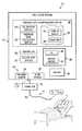
- FIG. 1illustrates an example breathing assistance system 10 for communicating gas to and/or from a patient, and for calculating and compensating for pressure drop associated with such gas communication, according to one embodiment of the disclosure
- FIG. 2illustrates an example graph of pressure drop versus flow rate of gas flow through an apparatus, including calibration test results and corresponding line segments, according to an example embodiment
- FIG. 3illustrates an example look-up table of coefficient pairs for line segment equations for use in calculating pressure drops for various flow rate values, according to an example embodiment of the disclosure.
- FIG. 4is a graph illustrating example empirical results obtained from testing various configurations of connection system apparatuses, which illustrates the non-linear nature of the relationship between pressure drop and flow rate through such connection system apparatuses.
- FIGS. 1-4Selected embodiments of the disclosure may be understood by reference, in part, to FIGS. 1-4 , wherein like numbers refer to same and like parts.
- the present disclosurerelates generally to methods for compensating for pressure drop in a breathing assistance system.
- a patient connection systeme.g., a patient circuit
- the pressure measured near the outlet of the gas delivery systeme.g., ventilator or CPAP box
- the pressure measured near the outlet of the gas delivery systemis typically greater than the actual pressure delivered to the patient in the case of positive flow in the direction of the patient, and lower than the actual pressure delivered to the patient in the case of negative flow in the direction of the patient.
- FIG. 1illustrates an example breathing assistance system 10 for communicating gas to and/or from a patient, and for calculating and compensating for pressure drop associated with such gas communication, according to one embodiment of the disclosure.
- Breathing assistance system 10may be generally configured to provide breathing assistance (e.g., providing ventilation and/or treating an apnea or other breathing condition) to a patient 11 .
- Breathing assistance system 10may include a ventilation system 12 and a connection system 14 for connecting ventilation system 12 to patient 11 .
- Ventilation system 12may comprise any device, apparatus, or system for delivering breathing gas to a patient, e.g., a ventilator, a respirator, a CPAP device, or a BiPAP device.
- Connection system 14may be generally configured to deliver gas from ventilation system 12 to patient 11 and/or to communicate exhaust gas away from patient 11 .
- connection system 14may comprise any suitable type of breathing circuit (e.g., a single-limb or dual-limb circuit) and/or a patient connection apparatus.
- connection system 14may include a 6-foot patient circuit.
- a patient connection apparatusmay include any device or devices configured to connect the breathing circuit to one or more breathing passageways of patient 11 .
- the patient connection apparatusmay include a patient connection tube directly connected to the patient's trachea, an artificial airway (e.g., an endotracheal tube or other device) inserted in the patient's trachea, and/or a mask, cushion or nasal pillows positioned over the patient's nose and/or mouth.
- an artificial airwaye.g., an endotracheal tube or other device
- a mask, cushion or nasal pillowspositioned over the patient's nose and/or mouth.
- Ventilation system 12may include a gas delivery system 20 , a controller 22 , one or more sensors 24 , user interfaces 26 , a display system 28 , and a pressure drop compensation system 30 .
- Gas delivery system 20may include any device or devices configured to generate, supply, and/or deliver gas (e.g., pressurized air) toward patient 11 via connection system 14 .
- gas delivery system 20may comprise a device capable of generating pressurized air (e.g., a motorized blower or piston-based device), a wall outlet through which pressurized air may be supplied (e.g., in a hospital or clinic), valves configured to control the supply of gas to the patient (e.g., a PSOL or other solenoid valve), one or more tanks of compressed gas, a compressor, or any other suitable source of pressurized or non-pressurized gas.
- a device capable of generating pressurized aire.g., a motorized blower or piston-based device
- a wall outlet through which pressurized air may be suppliede.g., in a hospital or clinic
- valvesconfigured to control the supply of gas to the patient (e.g., a PSOL or other solenoid valve), one or more tanks
- gas delivery system 20in cooperation with other components of ventilation system 12 (e.g., an exhalation valve) may generate both positive and negative gas flows toward patient 11 .
- a positive gas flowmay be generated as gas is delivered to patient 11 during inhalation, while a negative gas flow may be generated as exhaust gas is communicated from patient 11 during exhalation.
- gasmay refer to any one or more gases and/or vaporized substances suitable to be delivered to and/or from a patient via one or more breathing orifices (e.g., the nose and/or mouth), such as air, nitrogen, oxygen, any other component of air, CO 2 , vaporized water, vaporized medicines, and/or any combination of two or more of the above, for example.
- breathing orificese.g., the nose and/or mouth
- patientmay refer to any person or animal that may receive breathing assistance from system 10 , regardless of the medical status, official patient status, physical location, or any other characteristic of the person.
- patientsmay include persons under official medical care (e.g., hospital patients), persons not under official medical care, persons receiving care at a medical care facility, persons receiving home care, etc.
- Controller 22may be operable to control gas delivery system 20 to control the delivery of gas to and/or from patient 11 based on various input received from a user (e.g., via a touch screen and/or other user interfaces provided by ventilation system 12 ), data received from pressure drop compensation system 30 , and/or data received from one or more sensors 24 .
- controller 22may regulate the pressure and/or flow rate of gas delivered to and/or from a patient based at least on pressure and/or flow data received from sensors 24 and pressure drop data received from pressure drop compensation system 30 .
- Controller 22may include, or have access to, one or more processors, memory devices, and any other suitable hardware or software.
- the one or more memory devicesmay store instructions (e.g., any suitable software, algorithms, or other logic or instructions that may be executed by one or more processors) for automatically controlling the operation of ventilation system 12 (e.g., controlling the pressure and/or flow rate output by gas delivery system 20 ) based on any of the various input data discussed herein.
- sensors 24may be provided for sensing, detecting, and/or monitoring one or more parameters related to the ventilation of patient 11 , e.g., parameters regarding the ventilation provided by ventilation system 12 and/or physiological parameters regarding patient 11 .
- sensors 24may include one or more devices for measuring various parameters of gas flowing to or from patient 11 or ventilation system 12 , e.g., the pressure, flow rate, flow volume, temperature, gas content, and/or humidity of such gas flow.
- sensors 24may include a pressure sensor 34 and a flow sensor 36 for measuring the pressure and flow, respectively, of gas delivered from gas delivery system 20 .
- Sensors 34 and 36may be located at any suitable location in system 10 .
- each sensor 24may be integrated with or coupled to ventilation system 12 , integrated with or coupled to connection system 14 , coupled to patient 11 , or otherwise associated with system 10 .
- pressure sensor 34is located at or proximate a gas outlet of ventilation system 12 (e.g., at or proximate an outlet of gas delivery system 20 ).
- pressure sensor 34may be located inside or just outside a housing or enclosure of ventilation system 12 .
- pressure sensor 34may be positioned to measure the pressure of gas flow exiting ventilation system 12 or gas delivery system 20 , or the pressure of gas flow entering connection system 14 , as generally indicated by arrow “P 1 ” in FIG. 1 .
- flow sensor 36may be located at or proximate a gas outlet of ventilation system 12 (e.g., at or proximate an outlet of gas delivery system 20 ).
- flow sensor 36may be located inside or just outside a housing or enclosure of ventilation system 12 .
- flow sensor 36may be positioned to measure the flow rate of gas flow exiting ventilation system 12 or gas delivery system 20 , or the flow rate of gas flow entering connection system 14 .
- breathing assistance system 10may include a humidifier 70 , which may be integral with or separate from, ventilation system 12 .
- the humidifiermay be located and connected to system 10 in any suitable manner.
- the humidifier 70is located between the gas delivery system of the ventilation system 12 and the patient
- humidifier 70is located downstream of pressure sensor 34 , and may affect (e.g., increase) the pressure drop between pressure sensor 34 and the patient end of connection system 14 .
- Humidifier 70may include any known type of humidifier for use with a ventilator, CPAP system, or other type of breathing assistance system 10 .
- User interfaces 26may include any suitable device or devices allowing a user to interface with breathing assistance system 10 , e.g., to control ventilation system 12 , to navigate through various display screens, to make selections, and/or to set, modify, or otherwise control various parameters regarding system 10 .
- user interfaces 26may allow a user to input desired performance parameters (e.g., pressure or flow rate) that may be communicated to controller 22 to control the operation of gas delivery system 20 and/or other components of system 10 .
- User interfaces 26may include a graphic user interface (GUI) 40 , one or more manual input devices 42 separate from the GUI, and/or any other input devices.
- GUIgraphic user interface
- GUT 40may include a touch screen configured to display various information and provide an interface for accepting input from user (e.g., to navigate through various screens, to make selections, to set or modify various parameters, to change or configure the display, etc.).
- Manual input devices 42may include any physical buttons, knobs, dials, switches, levers) or any other devices that may be manipulated by a user.
- Display device 28may comprise a screen or any other device suitable for visually displaying medical data.
- display device 28may include a monitor, an LCD screen, LEDs, or any other visual device.
- display device 28 and user interfaces 26may be at least partially integrated, e.g., where ventilation system 12 includes a touch screen or other GUI 40 .
- Pressure drop compensation system 30may be generally configured to calculate the pressure drop of gas flowing through an apparatus of system 10 (e.g., connection system 14 or a portion thereof) such that controller 22 may compensate for such pressure drop in controlling or regulating gas delivery system 20 .
- Pressure drop compensation system 30may include a calibration module 50 , a pressure drop calculation module 52 , and one or more look-up tables 54 and/or equations 56 stored in memory 58 .
- Calibration module 50is generally configured to calibrate an apparatus 60 of system 10 for pressure drop calculations.
- Apparatus 60may comprise any one or more components of system 10 in which gas may experience a pressure drop.
- apparatus 60may comprise connection system 14 or a portion thereof, e.g., a patient circuit or patient hose with or without an attached patient connection apparatus (e.g., as defined above), with or without an attached humidifier 70 , or any combination of such components.
- Calibration module 50may be configured to perform one or more calibration tests for a particular type or a particular instance of an apparatus 60 in order to generate look-up tables 54 and/or equations 56 stored in memory 58 .
- calibration module 50may calibrate apparatus 60 during a calibration mode performed before connecting patient 11 to connection system 14 and/or before providing breathing assistance to patient 11 .
- calibration module 50may not be included.
- Look-up tables 54 and/or equations 56include data that may be used by pressure drop calculation module 52 for calculating a pressure drop in apparatus 60 while providing breathing assistance to patient 11 .
- look-up tables 54 and/or equations 56may be preloaded into memory 58 .
- look-up tables 54 and/or equations 56may be generated by calibration module 50 , as discussed above.
- Equations 56may include:
- Equations 56may be used to calculate or estimate pressure drop for positive and/or negative flow rates through apparatus 60 (e.g., in some configurations, a negative flow rate may be experienced during exhalation). In some embodiments, the same equations 56 may be used for both positive and negative flow situations. In other embodiments, separate equations 56 may be used for positive and negative flow situations. For example, Equations (1) through (6b) provided below include separate equations 56 for positive and negative flow situations.
- Look-up tables 54may include, for example, coefficients for any of equations 56 ,
- a look-up table 54may include coefficients defining each of multiple (e.g., 80) different linear line segments that collectively approximate a non-linear function between pressure drop and flow rate. Such coefficients in look-up tables 54 may be easily accessed and used for calculating or estimating the pressure drop or mask pressure while providing breathing assistance to a patient 11 .
- look-up tables 54may include different tables corresponding to different types and/or configurations of apparatuses 60 .
- look-up tables 54may include a first table of equation coefficients for use with a 6′ patient circuit and a second table of equation coefficients for use with an 8′ patient circuit.
- look-up tables 54may include a first table of equation coefficients for a configuration using a 6′ patient circuit and including a humidifier 70 , and a second table of equation coefficients for a configuration using the same 6′ patient circuit, but not including a humidifier 70 .
- look-up tables 54may include one set of equation coefficients for positive flow situations and another set of equation coefficients for negative flow situations.
- different equations 56may be used for positive and negative flow situations (e.g., Equations (1) through (6b) provided below)
- the same set of equation coefficientmay be used for both positive and negative flow situations.
- Pressure drop calculation module 52may be configured to use look-up tables 54 and/or equations 56 stored in memory 58 , along with any other suitable data (e.g., data from sensors 24 ) for calculating a pressure drop in apparatus 60 , e.g., while providing breathing assistance to patient 11 .
- pressure drop calculation module 52may use one or more equations 56 and/or equation coefficients store in a look-up table 54 to calculate pressure drop in apparatus 60 based on measured flow rate values received from flow sensor 36 .
- Calibration module 50 and/or pressure drop calculation module 52may include, or have access to, one or more processors (e.g., a microprocessor, a microcontroller, DSP, ASIC, FPGA, or any other suitable processor), tangible memory devices (e.g., RAM, DRAM, ROM, EPROM, Flash memory, one or more hard disks, and/or any other memory or storage device), and any other suitable hardware, software, or firmware.
- processorse.g., a microprocessor, a microcontroller, DSP, ASIC, FPGA, or any other suitable processor
- tangible memory devicese.g., RAM, DRAM, ROM, EPROM, Flash memory, one or more hard disks, and/or any other memory or storage device
- the one or more memory devicesmay store instructions (e.g., any suitable software, algorithms, or other logic or instructions that may be executed by one or more processors) for providing any of the functionality of such modules discussed herein.
- calibration module 50may be configured to calibrate a particular type, configuration, or instance of apparatus 60 by performing multiple pressure drop calibration tests and determining equation coefficients for multiple straight line segments approximating a non-linear relationship between pressure drop through apparatus 60 and flow rate through apparatus 60 .
- Each calibration testmay include determining a pressure drop in gas flowing through apparatus 60 at a particular flow rate.
- Each calibration testmay include delivering air through apparatus 60 with the distal end of apparatus 60 (i.e., opposite the end connected to ventilation system 12 ) left open such that the pressure at the distal end is atmospheric pressure, as indicated in FIG. 1 as P 0 .
- the pressure P 1 measured adjacent the outlet of ventilation system 12may be recorded as the pressure drop through apparatus 60 .
- Calibration module 50may perform calibration tests at any number of different flow rates, which may include positive flow rates, negative flow rates, or both. For example, calibration module 50 may perform calibration tests at 10 or more different flow rates to obtain 10 or more corresponding pressure drop values. In certain embodiments, calibration module 50 may perform about 80 calibration tests at 80 different flow rates to obtain 80 corresponding pressure drop values.
- FIG. 2illustrates an example plot of the results of calibration tests of an apparatus 60 at six positive flow rates (providing pressure drop data points PD 1 through PD 6 ) and six negative flow rates (providing pressure drop data points PD 1 ′ through PD 6 ′).
- calibration testsmay be performed and recorded using both positive and negative flow rates. In other embodiments, calibration tests may be performed and recorded using positive flow rates, and the results may simply be mirrored to provide the negative flow rate test results, which may reduce the total number of calibration tests by half.
- the pressure drop data pointsmay indicate a non-linear relationship between pressure drop and flow rate.
- calibration module 50may determine six pairs of coefficients A i and B i , each coefficient pair corresponding to one of the six lines L 1 through L 6 . These coefficient pairs may be stored in a look-up table 54 for use by pressure drop calculation module 52 to calculate estimated mask pressure values based on flow rate values measured by flow sensor 36 while providing breathing assistance to a patient 11 . As discussed below, these coefficient pairs may be used to calculate estimated mask pressure values for both positive flow and negative flow situations.
- pressure drop calculation module 52may access the appropriate look-up tables 54 based on input received from a user (e.g., via a user selection of a particular configuration or type of patient circuit) or automatically via other components of ventilation system 12 and/or connection system 14 (e.g., ventilation system 12 may automatically identify the particular type of patient circuit connected to ventilation system 12 , or whether a humidifier is connected to ventilation system 12 , and send appropriate signals to pressure drop calculation module 52 .
- FIG. 3illustrates an example look-up table 54 including 80 coefficient pairs for 80 line segments, for an example in which apparatus 60 comprises a 6 foot patient hose without a humidifier, according to an example embodiment of the disclosure.
- the coefficient pairs in look-up table 54may be used for calculating pressure drops in both positive flow and negative flow situations. For example, the same coefficient pair may be used for a measured flow rate of 1.5 l/s and a measured flow rate of ⁇ 1.5 l/s.
- calibration module 50 in ventilation system 12may perform the calibration process discussed above for a particular apparatus 60 connected to ventilation system 12 , and store the results in one or more look-up tables 54 .
- ventilation system 12may be used to calibrate a particular type, configuration, and/or instance of apparatus 60 to be used for providing breathing assistance to a patient 11 .
- Such calibrationmay be performed at any suitable time prior to providing breathing assistance to a patient 11 , e.g., just prior to initiating breathing assistance to patient 11 , upon the initial configuration of ventilation system 12 , or upon receiving a new type of apparatus 60 (e.g., a new brand or model of patient circuit).
- the calibration process discussed abovemay be performed on another ventilation system or during manufacturing of ventilation system 12 , and look-up tables 54 may be pre-loaded into memory 58 in ventilation system 12 .
- one or more look-up tables 54may be pre-loaded into memory 58 , but calibration module 50 may subsequently be used to generate and store additional took-up tables 54 (e.g., for new types or configurations of apparatus 60 ).
- calibration module 50may calculate or determine a non-linear function between pressure drop through apparatus 60 and flow rate through apparatus 60 .
- calibration module 50may generate one or more non-linear equation(s) that approximates the relationship between pressure drop and flow rate using some or all of the calibration test data points.
- Such non-linear equation(s)may include equations of any order (e.g., second order, third order, fourth order, etc.), which order may be selected by a user or selected automatically by calibration module 50 .
- Calibration module 50may generate such non-linear equation(s) using any known curve-fitting techniques or other suitable techniques.
- calibration module 50may be configured to automatically calibrate a particular type, configuration, or instance of apparatus 60 by generating a non-linear function between pressure drop through apparatus 60 and flow rate through apparatus 60 , and determining equation coefficients for multiple straight line segments approximating the generated non-linear function.
- the pressure drop in gas flowing through apparatus 60e.g., due to resistance and variances associated with apparatus 60
- FIG. 4is a graph 120 illustrating example empirical results obtained from testing two configurations of apparatus 60 —a 6′ patient circuit without a humidifier and the 6′ patient circuit with an attached humidifier—which illustrates the non-linear nature of the relationship between pressure drop and flow rate.
- graph 120only shows results for positive flow rates, similar results (but mirrored across the x- and y-axes) may be obtained for negative flow rates.
- Calibration module 50may solve for coefficients X and Y in Equation (5) by performing one or more pressure drop calibration tests at one or more positive and/or negative flow rates. Such calibration tests may be performed as discussed above, e.g., by delivering air through apparatus 60 with the distal end of apparatus 60 (i.e., opposite the end connected to ventilation system 12 ) left open such that the pressure at the distal end is atmospheric pressure, as indicated in FIG. 1 as P 0 .
- Equation (5)including coefficients X and Y solved based on the calibration test(s), may be stored in memory 58 . With coefficients X and Y being solved, Equation (5) may be used either directly or indirectly for calculating mask pressure values based on positive and/or negative flow rate values measured by flow sensor 36 while providing breathing assistance to a patient 11 , as discussed below.
- Equation (5)may be substituted into Equation (3a) to obtain Equation (6a):
- Estimated Mask PressureMeasured P 1 ⁇ [X *(Flow) 2 +Y *(Flow)] (6a)
- pressure drop calculation module 52may plug received flow rate values directly into Equation (6a) to directly calculate estimated mask pressure values in positive flow situations.
- Equation (5)may be substituted into Equation (3b) to obtain Equation (6b):
- Estimated Mask PressureMeasured P 1 +[X *(Flow) 2 +Y*ABS (Flow)] (6b)
- pressure drop calculation module 52may plug received flow rate values directly into Equation (6b) to directly calculate estimated mask pressure values in negative flow situations.
- calibration module 50may calculate coefficient pairs A i and B i for Equations (3a) and (3b) corresponding to each line segment.
- Estimated Mask PressureMeasured P 1 ⁇ ( A i *Flow+ B i ) (3a)
- Estimated Mask PressureMeasured P 1 +( A i *ABS (Flow)+ B i ) (3b)
- calibration module 50may calculate the pressure drop values for each of a number (e.g., 80) of flow rate values according to Equation (5), and use each adjacent pair of calculated pressure drop values as end-points for the multiple (e.g., 80) line segments collectively approximating the curve of Equation (5).
- such calculated coefficient pairs A i and B imay be stored in a look-up table 54 . Later, while providing breathing assistance to patient 11 , pressure drop calculation module 52 may access such look-up table 54 to calculate estimated mask pressure values based on flow rate values measured by flow sensor 36 using Equation (3a) (for positive flow rates) or Equation (3b) (for negative flow rates).
- ventilation system 12may be configured to automatically access the appropriate look-up tables 54 and/or equations 56 based on data entered by the user identifying apparatus 60 (e.g., a serial number, part number, or type of patient circuit and/or whether a humidifier is attached). In other embodiments, ventilation system 12 may be configured to automatically obtain identification information regarding apparatus 60 , and access the corresponding look-up tables 54 and/or equations 56 . For example, ventilation system 12 may be configured to automatically read data stored in non-volatile memory embedded in a patient circuit when the patient circuit is connected to ventilation system 12 . In such embodiments, ventilation system 12 may calibrate an apparatus 60 , or access the appropriate look-up tables 54 and/or equations 56 , automatically without user input.
- data entered by the user identifying apparatus 60e.g., a serial number, part number, or type of patient circuit and/or whether a humidifier is attached.
- ventilation system 12may be configured to automatically obtain identification information regarding apparatus 60 , and access the corresponding look-up tables 54 and/or equations
Landscapes
- Health & Medical Sciences (AREA)
- Emergency Medicine (AREA)
- Pulmonology (AREA)
- Engineering & Computer Science (AREA)
- Anesthesiology (AREA)
- Biomedical Technology (AREA)
- Heart & Thoracic Surgery (AREA)
- Hematology (AREA)
- Life Sciences & Earth Sciences (AREA)
- Animal Behavior & Ethology (AREA)
- General Health & Medical Sciences (AREA)
- Public Health (AREA)
- Veterinary Medicine (AREA)
- Measurement Of The Respiration, Hearing Ability, Form, And Blood Characteristics Of Living Organisms (AREA)
Abstract
Description
- one or more equations for calculating or estimating the pressure drop in gas flowing through apparatus60 (e.g., due to resistance and variances associated with apparatus60) as a function of the flow rate of gas flowing through
apparatus 60; and/or - one or more equations for calculating or estimating the “mask pressure,” compensating for the pressure drop of the gas flow through
apparatus 60. As used herein, the term “mask pressure” refers to the pressure at the outlet or patient end ofapparatus 60, regardless of whether a mask is used in the particular configuration.
- one or more equations for calculating or estimating the pressure drop in gas flowing through apparatus60 (e.g., due to resistance and variances associated with apparatus60) as a function of the flow rate of gas flowing through
Pressure Drop=Ai*ABS(Flow)+Bi (1)
- where “ABS(Flow)” is the absolute value of the measured flow rate (e.g., by flow sensor36).
Estimated Mask Pressure=MeasuredP1−Pressure Drop (2a)
or, substituting Equation (1) into Equation (2a):
Estimated Mask Pressure=MeasuredP1−(Ai*(Flow)+Bi) (3a)
- where “Measured P1” is the measured pressure at location P1, and “Flow” is the measured flow rate (e.g., by flow sensor36).
Estimated Mask Pressure=MeasuredP1+Pressure Drop (2b)
or, substituting Equation (1) into Equation (2b):
Estimated Mask Pressure=MeasuredP1+(Ai*ABS(Flow)+Bi) (3b)
- where “Measured P1” is the measured pressure at location P1, and “ABS(Flow)” is the absolute value of the measured flow rate (e.g., by flow sensor36).
Pressure Drop=Function (Flow) (4)
- where:
- “Pressure Drop” is the pressure drop in gas flowing through
apparatus 60, and - “Flow” is the flow rate of gas flowing through
apparatus 60.
- “Pressure Drop” is the pressure drop in gas flowing through
- where:
Pressure Drop=X*(Flow)2+Y*ABS(Flow) (5)
- where:
- “Pressure Drop” is the pressure drop in gas flowing through
apparatus 60, - “ABS(Flow)” is the absolute value of the flow rate through
apparatus 60, and - “X” and “Y” are coefficients.
- “Pressure Drop” is the pressure drop in gas flowing through
- where:
Estimated Mask Pressure=MeasuredP1−[X*(Flow)2+Y*(Flow)] (6a)
- where “Measured P1” is the measured pressure at location P1, and “Flow” is the measured flow rate (e.g., by flow sensor36),
Estimated Mask Pressure=MeasuredP1+[X*(Flow)2+Y*ABS(Flow)] (6b)
- where “Measured P1” is the measured pressure at location P1, “Flow” is the measured flow rate (e.g., by flow sensor36), and
- “ABS(Flow)” is the absolute value of “Flow”
- where “Measured P1” is the measured pressure at location P1, “Flow” is the measured flow rate (e.g., by flow sensor36), and
Estimated Mask Pressure=MeasuredP1−(Ai*Flow+Bi) (3a)
Estimated Mask Pressure=MeasuredP1+(Ai*ABS(Flow)+Bi) (3b)
Claims (11)
Pressure Drop=A*(Flow Rate)^2+B*(Flow Rate); and
Applications Claiming Priority (3)
| Application Number | Priority Date | Filing Date | Title |
|---|---|---|---|
| EP08006240.9AEP2106818B1 (en) | 2008-03-31 | 2008-03-31 | System for compensating for pressure drop in a breathing assistance system |
| EP08006240.9 | 2008-03-31 | ||
| EP08006240 | 2008-03-31 |
Publications (2)
| Publication Number | Publication Date |
|---|---|
| US20090241952A1 US20090241952A1 (en) | 2009-10-01 |
| US8353291B2true US8353291B2 (en) | 2013-01-15 |
Family
ID=39618909
Family Applications (1)
| Application Number | Title | Priority Date | Filing Date |
|---|---|---|---|
| US12/410,310Expired - Fee RelatedUS8353291B2 (en) | 2008-03-31 | 2009-03-24 | Systems and methods for compensating for pressure drop in a breathing assistance system |
Country Status (2)
| Country | Link |
|---|---|
| US (1) | US8353291B2 (en) |
| EP (1) | EP2106818B1 (en) |
Families Citing this family (110)
| Publication number | Priority date | Publication date | Assignee | Title |
|---|---|---|---|---|
| US5915379A (en) | 1997-03-14 | 1999-06-29 | Nellcor Puritan Bennett Incorporated | Graphic user interface for a patient ventilator |
| FR2858236B1 (en) | 2003-07-29 | 2006-04-28 | Airox | DEVICE AND METHOD FOR SUPPLYING RESPIRATORY GAS IN PRESSURE OR VOLUME |
| US8021310B2 (en) | 2006-04-21 | 2011-09-20 | Nellcor Puritan Bennett Llc | Work of breathing display for a ventilation system |
| US7784461B2 (en) | 2006-09-26 | 2010-08-31 | Nellcor Puritan Bennett Llc | Three-dimensional waveform display for a breathing assistance system |
| US8267085B2 (en) | 2009-03-20 | 2012-09-18 | Nellcor Puritan Bennett Llc | Leak-compensated proportional assist ventilation |
| US8792949B2 (en) | 2008-03-31 | 2014-07-29 | Covidien Lp | Reducing nuisance alarms |
| US10207069B2 (en) | 2008-03-31 | 2019-02-19 | Covidien Lp | System and method for determining ventilator leakage during stable periods within a breath |
| US8272380B2 (en) | 2008-03-31 | 2012-09-25 | Nellcor Puritan Bennett, Llc | Leak-compensated pressure triggering in medical ventilators |
| US8746248B2 (en) | 2008-03-31 | 2014-06-10 | Covidien Lp | Determination of patient circuit disconnect in leak-compensated ventilatory support |
| WO2009149357A1 (en) | 2008-06-06 | 2009-12-10 | Nellcor Puritan Bennett Llc | Systems and methods for ventilation in proportion to patient effort |
| WO2010028150A1 (en) | 2008-09-04 | 2010-03-11 | Nellcor Puritan Bennett Llc | Ventilator with controlled purge function |
| US8551006B2 (en) | 2008-09-17 | 2013-10-08 | Covidien Lp | Method for determining hemodynamic effects |
| US8424520B2 (en) | 2008-09-23 | 2013-04-23 | Covidien Lp | Safe standby mode for ventilator |
| WO2010036816A1 (en) | 2008-09-25 | 2010-04-01 | Nellcor Puritan Bennett Llc | Inversion-based feed-forward compensation of inspiratory trigger dynamics in medical ventilators |
| US8181648B2 (en) | 2008-09-26 | 2012-05-22 | Nellcor Puritan Bennett Llc | Systems and methods for managing pressure in a breathing assistance system |
| US8302602B2 (en) | 2008-09-30 | 2012-11-06 | Nellcor Puritan Bennett Llc | Breathing assistance system with multiple pressure sensors |
| US8393323B2 (en) | 2008-09-30 | 2013-03-12 | Covidien Lp | Supplemental gas safety system for a breathing assistance system |
| US8113062B2 (en) | 2008-09-30 | 2012-02-14 | Nellcor Puritan Bennett Llc | Tilt sensor for use with proximal flow sensing device |
| US8424521B2 (en) | 2009-02-27 | 2013-04-23 | Covidien Lp | Leak-compensated respiratory mechanics estimation in medical ventilators |
| US8418691B2 (en) | 2009-03-20 | 2013-04-16 | Covidien Lp | Leak-compensated pressure regulated volume control ventilation |
| US8776790B2 (en) | 2009-07-16 | 2014-07-15 | Covidien Lp | Wireless, gas flow-powered sensor system for a breathing assistance system |
| US8789529B2 (en) | 2009-08-20 | 2014-07-29 | Covidien Lp | Method for ventilation |
| US8439037B2 (en) | 2009-12-01 | 2013-05-14 | Covidien Lp | Exhalation valve assembly with integrated filter and flow sensor |
| US8439036B2 (en) | 2009-12-01 | 2013-05-14 | Covidien Lp | Exhalation valve assembly with integral flow sensor |
| AU2010327420C1 (en)* | 2009-12-01 | 2025-10-02 | Fisher & Paykel Healthcare Limited | Breathing assistance apparatus |
| US8469031B2 (en) | 2009-12-01 | 2013-06-25 | Covidien Lp | Exhalation valve assembly with integrated filter |
| US8469030B2 (en) | 2009-12-01 | 2013-06-25 | Covidien Lp | Exhalation valve assembly with selectable contagious/non-contagious latch |
| US8421465B2 (en) | 2009-12-02 | 2013-04-16 | Covidien Lp | Method and apparatus for indicating battery cell status on a battery pack assembly used during mechanical ventilation |
| US8424523B2 (en) | 2009-12-03 | 2013-04-23 | Covidien Lp | Ventilator respiratory gas accumulator with purge valve |
| US9119925B2 (en) | 2009-12-04 | 2015-09-01 | Covidien Lp | Quick initiation of respiratory support via a ventilator user interface |
| USD649157S1 (en) | 2009-12-04 | 2011-11-22 | Nellcor Puritan Bennett Llc | Ventilator display screen with a user interface |
| USD638852S1 (en) | 2009-12-04 | 2011-05-31 | Nellcor Puritan Bennett Llc | Ventilator display screen with an alarm icon |
| US8924878B2 (en) | 2009-12-04 | 2014-12-30 | Covidien Lp | Display and access to settings on a ventilator graphical user interface |
| US8335992B2 (en) | 2009-12-04 | 2012-12-18 | Nellcor Puritan Bennett Llc | Visual indication of settings changes on a ventilator graphical user interface |
| US20110132368A1 (en) | 2009-12-04 | 2011-06-09 | Nellcor Puritan Bennett Llc | Display Of Historical Alarm Status |
| US20110132369A1 (en) | 2009-12-04 | 2011-06-09 | Nellcor Puritan Bennett Llc | Ventilation System With System Status Display |
| US8499252B2 (en) | 2009-12-18 | 2013-07-30 | Covidien Lp | Display of respiratory data graphs on a ventilator graphical user interface |
| US9262588B2 (en) | 2009-12-18 | 2016-02-16 | Covidien Lp | Display of respiratory data graphs on a ventilator graphical user interface |
| EP2513480A1 (en) | 2009-12-18 | 2012-10-24 | K&Y Corporation | Infusion pump |
| US20110152697A1 (en)* | 2009-12-18 | 2011-06-23 | K&Y Corporation | Circulatory Pressure Monitoring Using Infusion Pump Systems |
| BR112012015035A2 (en)* | 2009-12-21 | 2017-06-27 | Koninl Philips Electronics Nv | pressure support system and method for automatically identifying a patient interface device in use with a pressure support system |
| US20110146683A1 (en)* | 2009-12-21 | 2011-06-23 | Nellcor Puritan Bennett Llc | Sensor Model |
| US8400290B2 (en) | 2010-01-19 | 2013-03-19 | Covidien Lp | Nuisance alarm reduction method for therapeutic parameters |
| US8707952B2 (en) | 2010-02-10 | 2014-04-29 | Covidien Lp | Leak determination in a breathing assistance system |
| US9302061B2 (en) | 2010-02-26 | 2016-04-05 | Covidien Lp | Event-based delay detection and control of networked systems in medical ventilation |
| US8453643B2 (en) | 2010-04-27 | 2013-06-04 | Covidien Lp | Ventilation system with system status display for configuration and program information |
| US8511306B2 (en) | 2010-04-27 | 2013-08-20 | Covidien Lp | Ventilation system with system status display for maintenance and service information |
| US8539949B2 (en) | 2010-04-27 | 2013-09-24 | Covidien Lp | Ventilation system with a two-point perspective view |
| US8638200B2 (en) | 2010-05-07 | 2014-01-28 | Covidien Lp | Ventilator-initiated prompt regarding Auto-PEEP detection during volume ventilation of non-triggering patient |
| US8607790B2 (en) | 2010-06-30 | 2013-12-17 | Covidien Lp | Ventilator-initiated prompt regarding auto-PEEP detection during pressure ventilation of patient exhibiting obstructive component |
| US8607788B2 (en) | 2010-06-30 | 2013-12-17 | Covidien Lp | Ventilator-initiated prompt regarding auto-PEEP detection during volume ventilation of triggering patient exhibiting obstructive component |
| US8607789B2 (en) | 2010-06-30 | 2013-12-17 | Covidien Lp | Ventilator-initiated prompt regarding auto-PEEP detection during volume ventilation of non-triggering patient exhibiting obstructive component |
| US8607791B2 (en) | 2010-06-30 | 2013-12-17 | Covidien Lp | Ventilator-initiated prompt regarding auto-PEEP detection during pressure ventilation |
| US8676285B2 (en) | 2010-07-28 | 2014-03-18 | Covidien Lp | Methods for validating patient identity |
| US8554298B2 (en) | 2010-09-21 | 2013-10-08 | Cividien LP | Medical ventilator with integrated oximeter data |
| US8757152B2 (en) | 2010-11-29 | 2014-06-24 | Covidien Lp | Ventilator-initiated prompt regarding detection of double triggering during a volume-control breath type |
| US8595639B2 (en) | 2010-11-29 | 2013-11-26 | Covidien Lp | Ventilator-initiated prompt regarding detection of fluctuations in resistance |
| US8757153B2 (en) | 2010-11-29 | 2014-06-24 | Covidien Lp | Ventilator-initiated prompt regarding detection of double triggering during ventilation |
| US8676529B2 (en) | 2011-01-31 | 2014-03-18 | Covidien Lp | Systems and methods for simulation and software testing |
| US8788236B2 (en) | 2011-01-31 | 2014-07-22 | Covidien Lp | Systems and methods for medical device testing |
| US8783250B2 (en) | 2011-02-27 | 2014-07-22 | Covidien Lp | Methods and systems for transitory ventilation support |
| US9038633B2 (en) | 2011-03-02 | 2015-05-26 | Covidien Lp | Ventilator-initiated prompt regarding high delivered tidal volume |
| US8714154B2 (en) | 2011-03-30 | 2014-05-06 | Covidien Lp | Systems and methods for automatic adjustment of ventilator settings |
| US9629971B2 (en) | 2011-04-29 | 2017-04-25 | Covidien Lp | Methods and systems for exhalation control and trajectory optimization |
| US8776792B2 (en) | 2011-04-29 | 2014-07-15 | Covidien Lp | Methods and systems for volume-targeted minimum pressure-control ventilation |
| DE11005677T1 (en)* | 2011-07-12 | 2013-07-25 | Healthc'air | Method of generating adequate pressure for a gas flow generator |
| US9089657B2 (en) | 2011-10-31 | 2015-07-28 | Covidien Lp | Methods and systems for gating user initiated increases in oxygen concentration during ventilation |
| US9364624B2 (en) | 2011-12-07 | 2016-06-14 | Covidien Lp | Methods and systems for adaptive base flow |
| US9498589B2 (en) | 2011-12-31 | 2016-11-22 | Covidien Lp | Methods and systems for adaptive base flow and leak compensation |
| US9022031B2 (en) | 2012-01-31 | 2015-05-05 | Covidien Lp | Using estimated carinal pressure for feedback control of carinal pressure during ventilation |
| US8844526B2 (en) | 2012-03-30 | 2014-09-30 | Covidien Lp | Methods and systems for triggering with unknown base flow |
| US9327089B2 (en) | 2012-03-30 | 2016-05-03 | Covidien Lp | Methods and systems for compensation of tubing related loss effects |
| US9993604B2 (en) | 2012-04-27 | 2018-06-12 | Covidien Lp | Methods and systems for an optimized proportional assist ventilation |
| US9144658B2 (en) | 2012-04-30 | 2015-09-29 | Covidien Lp | Minimizing imposed expiratory resistance of mechanical ventilator by optimizing exhalation valve control |
| US10362967B2 (en) | 2012-07-09 | 2019-07-30 | Covidien Lp | Systems and methods for missed breath detection and indication |
| US9027552B2 (en) | 2012-07-31 | 2015-05-12 | Covidien Lp | Ventilator-initiated prompt or setting regarding detection of asynchrony during ventilation |
| WO2014057457A2 (en)* | 2012-10-10 | 2014-04-17 | Koninklijke Philips N.V. | Adaptive patient circuit compensation with pressure sensor at mask apparatus |
| US9375542B2 (en) | 2012-11-08 | 2016-06-28 | Covidien Lp | Systems and methods for monitoring, managing, and/or preventing fatigue during ventilation |
| US9289573B2 (en) | 2012-12-28 | 2016-03-22 | Covidien Lp | Ventilator pressure oscillation filter |
| US9492629B2 (en) | 2013-02-14 | 2016-11-15 | Covidien Lp | Methods and systems for ventilation with unknown exhalation flow and exhalation pressure |
| USD731049S1 (en) | 2013-03-05 | 2015-06-02 | Covidien Lp | EVQ housing of an exhalation module |
| USD692556S1 (en) | 2013-03-08 | 2013-10-29 | Covidien Lp | Expiratory filter body of an exhalation module |
| USD731065S1 (en) | 2013-03-08 | 2015-06-02 | Covidien Lp | EVQ pressure sensor filter of an exhalation module |
| USD701601S1 (en) | 2013-03-08 | 2014-03-25 | Covidien Lp | Condensate vial of an exhalation module |
| USD744095S1 (en) | 2013-03-08 | 2015-11-24 | Covidien Lp | Exhalation module EVQ internal flow sensor |
| USD693001S1 (en) | 2013-03-08 | 2013-11-05 | Covidien Lp | Neonate expiratory filter assembly of an exhalation module |
| USD731048S1 (en) | 2013-03-08 | 2015-06-02 | Covidien Lp | EVQ diaphragm of an exhalation module |
| USD736905S1 (en) | 2013-03-08 | 2015-08-18 | Covidien Lp | Exhalation module EVQ housing |
| US9358355B2 (en) | 2013-03-11 | 2016-06-07 | Covidien Lp | Methods and systems for managing a patient move |
| US9981096B2 (en) | 2013-03-13 | 2018-05-29 | Covidien Lp | Methods and systems for triggering with unknown inspiratory flow |
| US9950135B2 (en) | 2013-03-15 | 2018-04-24 | Covidien Lp | Maintaining an exhalation valve sensor assembly |
| US10064583B2 (en) | 2013-08-07 | 2018-09-04 | Covidien Lp | Detection of expiratory airflow limitation in ventilated patient |
| US9675771B2 (en) | 2013-10-18 | 2017-06-13 | Covidien Lp | Methods and systems for leak estimation |
| WO2015058089A1 (en) | 2013-10-18 | 2015-04-23 | Silverbow Development Llc | Techniques for determining patient airway pressure |
| US9808591B2 (en) | 2014-08-15 | 2017-11-07 | Covidien Lp | Methods and systems for breath delivery synchronization |
| US9950129B2 (en) | 2014-10-27 | 2018-04-24 | Covidien Lp | Ventilation triggering using change-point detection |
| EP3212263B1 (en)* | 2014-10-28 | 2025-02-26 | Fisher & Paykel Healthcare Limited | Patient specific auto-flowrate control |
| US9925346B2 (en) | 2015-01-20 | 2018-03-27 | Covidien Lp | Systems and methods for ventilation with unknown exhalation flow |
| USD775345S1 (en) | 2015-04-10 | 2016-12-27 | Covidien Lp | Ventilator console |
| JP2018519083A (en)* | 2015-06-30 | 2018-07-19 | コーニンクレッカ フィリップス エヌ ヴェKoninklijke Philips N.V. | Barometric pressure sensor for variable resistance positive airway pressure device circuit compensation |
| US10765822B2 (en) | 2016-04-18 | 2020-09-08 | Covidien Lp | Endotracheal tube extubation detection |
| AU2018353928B2 (en) | 2017-11-14 | 2019-06-13 | Covidien Lp | Methods and systems for drive pressure spontaneous ventilation |
| US20190201647A1 (en)* | 2017-12-28 | 2019-07-04 | Koninklijke Philips N.V. | System and method for providing high-flow nasal therapy |
| CN114793424A (en)* | 2019-10-14 | 2022-07-26 | 瑞思迈私人有限公司 | Characterization System for Respiratory Therapy |
| US11672934B2 (en) | 2020-05-12 | 2023-06-13 | Covidien Lp | Remote ventilator adjustment |
| CN113842528B (en)* | 2020-06-28 | 2023-08-22 | 南京理工大学 | A pressure differential controlled high flow ventilation method and system |
| US20220362496A1 (en)* | 2021-05-14 | 2022-11-17 | Telesair, Inc. | Method for controlling oxygen-containing gas and related products |
| US20230001126A1 (en)* | 2021-07-01 | 2023-01-05 | Sunil Nanda | Ventilator |
| JP2024538633A (en)* | 2021-09-29 | 2024-10-23 | レスメド・プロプライエタリー・リミテッド | Characterization system for respiratory therapy |
| CN113877031A (en)* | 2021-09-30 | 2022-01-04 | 深圳市科曼医疗设备有限公司 | Method and device for calculating leakage flow rate of breathing machine, computer equipment and storage medium |
Citations (31)
| Publication number | Priority date | Publication date | Assignee | Title |
|---|---|---|---|---|
| WO1990004425A2 (en) | 1988-10-24 | 1990-05-03 | Antec Systems Limited | Gas sampling device and water trap |
| US4967744A (en) | 1988-11-03 | 1990-11-06 | Airoflex Medical, Inc. | Flexible breathing circuit |
| US5099836A (en) | 1987-10-05 | 1992-03-31 | Hudson Respiratory Care Inc. | Intermittent oxygen delivery system and cannula |
| US5111827A (en) | 1988-02-11 | 1992-05-12 | Instrumentarium Corp. | Respiratory sampling device |
| US5370122A (en) | 1992-11-18 | 1994-12-06 | Kunig; Horst E. | Method and apparatus for measuring myocardial impairment, dysfunctions, sufficiency, and insufficiency |
| US5494051A (en) | 1994-09-14 | 1996-02-27 | Cardi-Act, L.L.C. | Patient-transport apparatus |
| US5551419A (en)* | 1994-12-15 | 1996-09-03 | Devilbiss Health Care, Inc. | Control for CPAP apparatus |
| US5794614A (en) | 1989-05-19 | 1998-08-18 | Gruenke; Roger A. | Apparatus for compensating for flow and pressure variances in pneumatic circuits |
| US5969429A (en) | 1997-08-15 | 1999-10-19 | The United States Of America As Represented By The Secretary Of The Navy | Breathing apparatus having electrical power supply arrangement with turbine-generator assembly |
| US6135106A (en) | 1997-08-22 | 2000-10-24 | Nellcor Puritan-Bennett, Inc. | CPAP pressure and flow transducer |
| US20020116994A1 (en) | 2001-02-01 | 2002-08-29 | Erkki Heinonen | Method and apparatus for determining a zero gas flow state in a bidirectional gas flow conduit |
| FR2824907A1 (en) | 2001-05-21 | 2002-11-22 | Taema | System for monitoring hydraulic or pneumatic systems for flow rate and pressure has an autonomous power supply derived from the fluid flow itself, as a turbine generator is used to charge accumulators which supply system power |
| FR2829942A1 (en) | 2001-09-27 | 2003-03-28 | Taema | Measurement of flow rates in an artificial respirator for medical use with only a single respiratory branch, whereby a differential pressure is measured and related to the inspiration or expiration mass flow rate |
| US20040015058A1 (en) | 1993-09-04 | 2004-01-22 | Motorola, Inc. | Wireless medical diagnosis and monitoring equipment |
| US20040118403A1 (en)* | 2000-12-29 | 2004-06-24 | O'connor Gerard Michael | Characterisation of mask systems |
| US20050217275A1 (en) | 2004-04-05 | 2005-10-06 | Hendrickson James A | Devices, systems and methods for generating electricity from gases stored in containers under pressure |
| US20060162728A1 (en)* | 2002-03-08 | 2006-07-27 | Kaerys S.A. | Air assistance apparatus for computing the airflow provided by only means of pressure sensors |
| US7089930B2 (en) | 2002-08-20 | 2006-08-15 | Audiopack Technologies, Inc. | Wireless heads-up display for a self-contained breathing apparatus |
| US7101341B2 (en) | 2003-04-15 | 2006-09-05 | Ross Tsukashima | Respiratory monitoring, diagnostic and therapeutic system |
| WO2006138578A2 (en) | 2005-06-17 | 2006-12-28 | Salter Labs | Pressure sensing device with test circuit |
| US20070100222A1 (en) | 2004-06-14 | 2007-05-03 | Metronic Minimed, Inc. | Analyte sensing apparatus for hospital use |
| US20080021339A1 (en) | 2005-10-27 | 2008-01-24 | Gabriel Jean-Christophe P | Anesthesia monitor, capacitance nanosensors and dynamic sensor sampling method |
| US20080092898A1 (en) | 2004-08-27 | 2008-04-24 | John Hopkins University | Disposable Sleep And Breathing Monitor |
| US20080167614A1 (en) | 2007-01-08 | 2008-07-10 | David Tolkowsky | Endobronchial fluid exhaler devices and methods for use thereof |
| US20080177404A1 (en) | 1999-02-12 | 2008-07-24 | Pierre Bonnat | Method and System for Controlling a User Interface of a Device Using Human Breath |
| US20080200776A1 (en) | 2007-02-17 | 2008-08-21 | Drager Medical Ag & Co. Kg | Patient connection for the artificial respiration of a patient |
| US20090044805A1 (en) | 2007-08-17 | 2009-02-19 | Resmed Limited | Methods and apparatus for pressure therapy in the treatment of sleep disordered breathing |
| US20090320842A1 (en) | 2006-09-07 | 2009-12-31 | Renee Frances Doherty | Mask and flow generator system |
| US7658891B1 (en) | 1997-11-21 | 2010-02-09 | Barnes Ronald L | Air purification and decontamination for hazmat suits |
| US20110162647A1 (en) | 2008-09-10 | 2011-07-07 | Resmed Limited | Power management in respiratory treatment apparatus |
| US20120053431A1 (en)* | 2000-04-17 | 2012-03-01 | Nellcor Puritan Bennett Llc | Pulse oximeter sensor with piece-wise function |
Family Cites Families (2)
| Publication number | Priority date | Publication date | Assignee | Title |
|---|---|---|---|---|
| US710341A (en)* | 1900-08-15 | 1902-09-30 | William H Rymer | Bucket or manger. |
| SE0002449D0 (en)* | 2000-06-29 | 2000-06-29 | Siemens Elema Ab | Method and arrangement for evaluating effective flow resistance of a patient breathing circuit |
- 2008
- 2008-03-31EPEP08006240.9Apatent/EP2106818B1/enactiveActive
- 2009
- 2009-03-24USUS12/410,310patent/US8353291B2/ennot_activeExpired - Fee Related
Patent Citations (34)
| Publication number | Priority date | Publication date | Assignee | Title |
|---|---|---|---|---|
| US5099836A (en) | 1987-10-05 | 1992-03-31 | Hudson Respiratory Care Inc. | Intermittent oxygen delivery system and cannula |
| US5111827A (en) | 1988-02-11 | 1992-05-12 | Instrumentarium Corp. | Respiratory sampling device |
| WO1990004425A2 (en) | 1988-10-24 | 1990-05-03 | Antec Systems Limited | Gas sampling device and water trap |
| US4967744A (en) | 1988-11-03 | 1990-11-06 | Airoflex Medical, Inc. | Flexible breathing circuit |
| US5794614A (en) | 1989-05-19 | 1998-08-18 | Gruenke; Roger A. | Apparatus for compensating for flow and pressure variances in pneumatic circuits |
| US5370122A (en) | 1992-11-18 | 1994-12-06 | Kunig; Horst E. | Method and apparatus for measuring myocardial impairment, dysfunctions, sufficiency, and insufficiency |
| US20040015058A1 (en) | 1993-09-04 | 2004-01-22 | Motorola, Inc. | Wireless medical diagnosis and monitoring equipment |
| US5494051A (en) | 1994-09-14 | 1996-02-27 | Cardi-Act, L.L.C. | Patient-transport apparatus |
| US5749374A (en) | 1994-09-14 | 1998-05-12 | Cardi-Act, L.L.C. | Patient-transport and treatment apparatus |
| US5551419A (en)* | 1994-12-15 | 1996-09-03 | Devilbiss Health Care, Inc. | Control for CPAP apparatus |
| US5969429A (en) | 1997-08-15 | 1999-10-19 | The United States Of America As Represented By The Secretary Of The Navy | Breathing apparatus having electrical power supply arrangement with turbine-generator assembly |
| US6135106A (en) | 1997-08-22 | 2000-10-24 | Nellcor Puritan-Bennett, Inc. | CPAP pressure and flow transducer |
| US7658891B1 (en) | 1997-11-21 | 2010-02-09 | Barnes Ronald L | Air purification and decontamination for hazmat suits |
| US20080177404A1 (en) | 1999-02-12 | 2008-07-24 | Pierre Bonnat | Method and System for Controlling a User Interface of a Device Using Human Breath |
| US20120053431A1 (en)* | 2000-04-17 | 2012-03-01 | Nellcor Puritan Bennett Llc | Pulse oximeter sensor with piece-wise function |
| US20040118403A1 (en)* | 2000-12-29 | 2004-06-24 | O'connor Gerard Michael | Characterisation of mask systems |
| US20020116994A1 (en) | 2001-02-01 | 2002-08-29 | Erkki Heinonen | Method and apparatus for determining a zero gas flow state in a bidirectional gas flow conduit |
| FR2824907A1 (en) | 2001-05-21 | 2002-11-22 | Taema | System for monitoring hydraulic or pneumatic systems for flow rate and pressure has an autonomous power supply derived from the fluid flow itself, as a turbine generator is used to charge accumulators which supply system power |
| FR2829942A1 (en) | 2001-09-27 | 2003-03-28 | Taema | Measurement of flow rates in an artificial respirator for medical use with only a single respiratory branch, whereby a differential pressure is measured and related to the inspiration or expiration mass flow rate |
| US20060162728A1 (en)* | 2002-03-08 | 2006-07-27 | Kaerys S.A. | Air assistance apparatus for computing the airflow provided by only means of pressure sensors |
| US7089930B2 (en) | 2002-08-20 | 2006-08-15 | Audiopack Technologies, Inc. | Wireless heads-up display for a self-contained breathing apparatus |
| US7101341B2 (en) | 2003-04-15 | 2006-09-05 | Ross Tsukashima | Respiratory monitoring, diagnostic and therapeutic system |
| US7297120B2 (en) | 2003-04-15 | 2007-11-20 | Sierra Medical Technology, Inc. | Respiratory monitoring, diagnostic and therapeutic system |
| US20050217275A1 (en) | 2004-04-05 | 2005-10-06 | Hendrickson James A | Devices, systems and methods for generating electricity from gases stored in containers under pressure |
| US20070100222A1 (en) | 2004-06-14 | 2007-05-03 | Metronic Minimed, Inc. | Analyte sensing apparatus for hospital use |
| US20080092898A1 (en) | 2004-08-27 | 2008-04-24 | John Hopkins University | Disposable Sleep And Breathing Monitor |
| WO2006138578A2 (en) | 2005-06-17 | 2006-12-28 | Salter Labs | Pressure sensing device with test circuit |
| US20080021339A1 (en) | 2005-10-27 | 2008-01-24 | Gabriel Jean-Christophe P | Anesthesia monitor, capacitance nanosensors and dynamic sensor sampling method |
| US20090320842A1 (en) | 2006-09-07 | 2009-12-31 | Renee Frances Doherty | Mask and flow generator system |
| US20080167614A1 (en) | 2007-01-08 | 2008-07-10 | David Tolkowsky | Endobronchial fluid exhaler devices and methods for use thereof |
| US7985254B2 (en) | 2007-01-08 | 2011-07-26 | David Tolkowsky | Endobronchial fluid exhaler devices and methods for use thereof |
| US20080200776A1 (en) | 2007-02-17 | 2008-08-21 | Drager Medical Ag & Co. Kg | Patient connection for the artificial respiration of a patient |
| US20090044805A1 (en) | 2007-08-17 | 2009-02-19 | Resmed Limited | Methods and apparatus for pressure therapy in the treatment of sleep disordered breathing |
| US20110162647A1 (en) | 2008-09-10 | 2011-07-07 | Resmed Limited | Power management in respiratory treatment apparatus |
Non-Patent Citations (5)
| Title |
|---|
| "GoodKnight® 425 GoodKnight® 425ST Clinician and Home Care Provider Manual", Puritan Bennett, Revision G, p. 25, referring to breathing circuits having an "internal pressure sensor line", Mar. 2010. |
| "Puritan Bennett CPAP / BiLEVEL Tubing with Internal Pressure Sensor Line", Printout of page from website www.cpapxchange.com, 2 pages, Printed Jun. 9, 2010. |
| Application for Letters Patent, "System and Process for Supplying Respiratory Gas Under Pressure or Volumetrically," Inventor Claude Andreiux, 21 pages, Filed Jul. 27, 2004. |
| International PCT Search Report and Written Opinion, PCT/US2009/055288, 17 pages, Mailed Dec. 4, 2009. |
| International PCT Search Report and Written Opinion, PCT/US2010/035453, 13 pages, Sep. 20, 2010. |
Also Published As
| Publication number | Publication date |
|---|---|
| EP2106818A1 (en) | 2009-10-07 |
| US20090241952A1 (en) | 2009-10-01 |
| EP2106818B1 (en) | 2013-12-25 |
Similar Documents
| Publication | Publication Date | Title |
|---|---|---|
| US8353291B2 (en) | Systems and methods for compensating for pressure drop in a breathing assistance system | |
| US8181648B2 (en) | Systems and methods for managing pressure in a breathing assistance system | |
| US20250001122A1 (en) | Humidification of respiratory gases | |
| US8312879B2 (en) | Method and apparatus for airway compensation control | |
| JP4307811B2 (en) | Operating system and respiratory system for examination of pulmonary mechanics of respiratory system | |
| JP4938185B2 (en) | Method and apparatus for evaluating the effective flow resistance of a patient breathing circuit | |
| US11752285B2 (en) | System and method for accurate estimation of intentional and unintentional leaks in flow generation systems | |
| US20070272241A1 (en) | System and Method for Scheduling Pause Maneuvers Used for Estimating Elastance and/or Resistance During Breathing | |
| CN107106801B (en) | System and method for detecting ventilator disconnection from a patient using estimated patient lung compliance over both inhalation and exhalation phases of respiration | |
| US20110307194A1 (en) | Characterisation of mask systems | |
| US20110146681A1 (en) | Adaptive Flow Sensor Model | |
| US20130012828A1 (en) | Method and System for Measuring Nasal Resistance to Airflow | |
| US20160015927A1 (en) | Rainout protection for respiratory therapy including humidification | |
| TWI861076B (en) | A respiratory system for providing bubble cpap | |
| CN107787238B (en) | Oxygenation during mechanical ventilation of a patient | |
| US20210052839A1 (en) | Anterior interface pressure monitoring during ventilation | |
| US11052207B2 (en) | Gas sensing apparatus | |
| US20250288770A1 (en) | Medical ventilator displaying the airway opening pressure of the patient | |
| US20160325068A1 (en) | Measuring flow in a respiratory therapy device |
Legal Events
| Date | Code | Title | Description |
|---|---|---|---|
| AS | Assignment | Owner name:NELLCOR PURITAN BENNETT LLC, COLORADO Free format text:ASSIGNMENT OF ASSIGNORS INTEREST;ASSIGNORS:NICOLAZZI, PASCAL;GENTNER, JULIEN;MOUGEL, LAURENT;AND OTHERS;REEL/FRAME:022476/0269;SIGNING DATES FROM 20090130 TO 20090205 Owner name:NELLCOR PURITAN BENNETT LLC, COLORADO Free format text:ASSIGNMENT OF ASSIGNORS INTEREST;ASSIGNORS:NICOLAZZI, PASCAL;GENTNER, JULIEN;MOUGEL, LAURENT;AND OTHERS;SIGNING DATES FROM 20090130 TO 20090205;REEL/FRAME:022476/0269 | |
| AS | Assignment | Owner name:COVIDIEN LP, MASSACHUSETTS Free format text:ASSIGNMENT OF ASSIGNORS INTEREST;ASSIGNOR:NELLCOR PURITAN BENNETT LLC;REEL/FRAME:029384/0686 Effective date:20120929 | |
| STCF | Information on status: patent grant | Free format text:PATENTED CASE | |
| FPAY | Fee payment | Year of fee payment:4 | |
| MAFP | Maintenance fee payment | Free format text:PAYMENT OF MAINTENANCE FEE, 8TH YEAR, LARGE ENTITY (ORIGINAL EVENT CODE: M1552); ENTITY STATUS OF PATENT OWNER: LARGE ENTITY Year of fee payment:8 | |
| FEPP | Fee payment procedure | Free format text:MAINTENANCE FEE REMINDER MAILED (ORIGINAL EVENT CODE: REM.); ENTITY STATUS OF PATENT OWNER: LARGE ENTITY | |
| LAPS | Lapse for failure to pay maintenance fees | Free format text:PATENT EXPIRED FOR FAILURE TO PAY MAINTENANCE FEES (ORIGINAL EVENT CODE: EXP.); ENTITY STATUS OF PATENT OWNER: LARGE ENTITY | |
| STCH | Information on status: patent discontinuation | Free format text:PATENT EXPIRED DUE TO NONPAYMENT OF MAINTENANCE FEES UNDER 37 CFR 1.362 | |
| FP | Lapsed due to failure to pay maintenance fee | Effective date:20250115 |