US8353169B2 - Supersonic cooling system - Google Patents
Supersonic cooling systemDownload PDFInfo
- Publication number
- US8353169B2 US8353169B2US12/961,342US96134210AUS8353169B2US 8353169 B2US8353169 B2US 8353169B2US 96134210 AUS96134210 AUS 96134210AUS 8353169 B2US8353169 B2US 8353169B2
- Authority
- US
- United States
- Prior art keywords
- fluid
- evaporator
- flow path
- pressure region
- cooling system
- Prior art date
- Legal status (The legal status is an assumption and is not a legal conclusion. Google has not performed a legal analysis and makes no representation as to the accuracy of the status listed.)
- Expired - Fee Related
Links
Images


Classifications
- F—MECHANICAL ENGINEERING; LIGHTING; HEATING; WEAPONS; BLASTING
- F25—REFRIGERATION OR COOLING; COMBINED HEATING AND REFRIGERATION SYSTEMS; HEAT PUMP SYSTEMS; MANUFACTURE OR STORAGE OF ICE; LIQUEFACTION SOLIDIFICATION OF GASES
- F25B—REFRIGERATION MACHINES, PLANTS OR SYSTEMS; COMBINED HEATING AND REFRIGERATION SYSTEMS; HEAT PUMP SYSTEMS
- F25B1/00—Compression machines, plants or systems with non-reversible cycle
- F25B1/06—Compression machines, plants or systems with non-reversible cycle with compressor of jet type, e.g. using liquid under pressure
- F—MECHANICAL ENGINEERING; LIGHTING; HEATING; WEAPONS; BLASTING
- F04—POSITIVE - DISPLACEMENT MACHINES FOR LIQUIDS; PUMPS FOR LIQUIDS OR ELASTIC FLUIDS
- F04B—POSITIVE-DISPLACEMENT MACHINES FOR LIQUIDS; PUMPS
- F04B17/00—Pumps characterised by combination with, or adaptation to, specific driving engines or motors
- F04B17/03—Pumps characterised by combination with, or adaptation to, specific driving engines or motors driven by electric motors
- F—MECHANICAL ENGINEERING; LIGHTING; HEATING; WEAPONS; BLASTING
- F25—REFRIGERATION OR COOLING; COMBINED HEATING AND REFRIGERATION SYSTEMS; HEAT PUMP SYSTEMS; MANUFACTURE OR STORAGE OF ICE; LIQUEFACTION SOLIDIFICATION OF GASES
- F25B—REFRIGERATION MACHINES, PLANTS OR SYSTEMS; COMBINED HEATING AND REFRIGERATION SYSTEMS; HEAT PUMP SYSTEMS
- F25B41/00—Fluid-circulation arrangements
- F25B41/30—Expansion means; Dispositions thereof
- F—MECHANICAL ENGINEERING; LIGHTING; HEATING; WEAPONS; BLASTING
- F25—REFRIGERATION OR COOLING; COMBINED HEATING AND REFRIGERATION SYSTEMS; HEAT PUMP SYSTEMS; MANUFACTURE OR STORAGE OF ICE; LIQUEFACTION SOLIDIFICATION OF GASES
- F25B—REFRIGERATION MACHINES, PLANTS OR SYSTEMS; COMBINED HEATING AND REFRIGERATION SYSTEMS; HEAT PUMP SYSTEMS
- F25B41/00—Fluid-circulation arrangements
- F25B41/40—Fluid line arrangements
Definitions
- the present inventiongenerally relates to cooling systems.
- the present inventionmore specifically relates to supersonic cooling systems.
- a vapor compression system as known in the artgenerally includes a compressor, a condenser, and an evaporator. These systems also include an expansion device.
- a gasis compressed whereby the temperature of that gas is increased beyond that of the ambient temperature.
- the compressed gasis then run through a condenser and turned into a liquid.
- the condensed and liquefied gasis then taken through an expansion device, which drops the pressure and the corresponding temperature.
- the resulting refrigerantis then boiled in an evaporator.
- This vapor compression cycleis generally known to those of skill in the art.
- FIG. 1illustrates a vapor compression system 100 as might be found in the prior art.
- compressor 110compresses the gas to (approximately) 238 pounds per square inch (PSI) and a temperature of 190 F.
- Condenser 120then liquefies the heated and compressed gas to (approximately) 220 PSI and 117 F.
- the gas that was liquefied by the condenser ( 120 )is then passed through the expansion valve 130 of FIG. 1 .
- the pressureis dropped to (approximately) 20 PSI.
- a corresponding drop in temperatureaccompanies the drop in pressure, which is reflected as a temperature drop to (approximately) 34 F in FIG. 1 .
- the refrigerant that results from dropping the pressure and temperature at the expansion value 130is boiled at evaporator 140 . Through boiling of the refrigerant by evaporator 140 , a low temperature vapor results, which is illustrated in FIG. 1 as having (approximately) a temperature of 39 F and a corresponding pressure of 20 PSI.
- the cycle related to the system 100 of FIG. 1is sometimes referred to as the vapor compression cycle. Such a cycle generally results in a coefficient of performance (COP) between 2.4 and 3.5.
- the coefficient of performance, as reflected in FIG. 1is the evaporator cooling power or capacity divided by compressor power. It should be noted that the temperature and PSI references that are reflected in FIG. 1 are exemplary and illustrative.
- FIG. 2illustrates the performance of a vapor compression system like that illustrated in FIG. 1 .
- the COP illustrated in FIG. 2corresponds to a typical home or automotive vapor compression system—like that of FIG. 1 —with an ambient temperature of (approximately) 90 F.
- the COP shown in FIG. 2further corresponds to a vapor compression system utilizing a fixed orifice tube system.
- Such a system 100operates at an efficiency rate (e.g., coefficient of performance) that is far below that of system potential.
- efficiency ratee.g., coefficient of performance
- To compress gas in a conventional vapor compression system ( 100 ) like that illustrated in FIG. 1typically takes 1.75-2.5 kilowatts for every 5 kilowatts of cooling power. This exchange rate is less than optimal and directly correlates to the rise in pressure times the volumetric flow rate. Degraded performance is similarly and ultimately related to performance (or lack thereof) by the compressor ( 110 ).
- Haloalkane refrigerantssuch as tetrafluoroethane (CH 2 FCF 3 ) are inert gases that are commonly used as high-temperature refrigerants in refrigerators and automobile air conditioners. Tetrafluoroethane have also been used to cool over-clocked computers. These inert, refrigerant gases are more commonly referred to as R-134 gases. The volume of an R-134 gas can be 600-1000 times greater than the corresponding liquid. As such, there is a need in the art for an improved cooling system that more fully recognizes system potential and overcomes technical barriers related to compressor performance.
- a supersonic cooling systemin a first claimed embodiment of the present invention, includes a pump that maintains a circulatory fluid flow through a flow path and an evaporator.
- the evaporatoroperates in the critical flow regime and generates a compression wave.
- the compression waveshocks the maintained fluid flow thereby changing the PSI of the maintained fluid flow and exchanges heat introduced into the fluid flow.
- the pump and evaporatorare located within a housing.
- the housingmay correspond to the shape of a pumpkin.
- An external surface of the housingmay effectuate forced convection and a further exchange of heat introduced into the compression system.
- the pump of the first claimed embodimentmay maintain the circulatory fluid flow by using vortex flow rings.
- the pumpmay progressively introduce energy to the vortex flow rings such that the energy introduced corresponds to energy being lost through dissipation.
- a second claimed embodiment of the present inventionsets for a cooling method.
- a compression waveis established in a compressible fluid.
- the compressible liquidis transported from a high pressure region to a low pressure region and the corresponding velocity of the fluid is greater or equal to the speed of sound in the compressible fluid.
- Heat that has been introduced into the fluid flowis exchanged as a part of a phase change of the compressible fluid.
- FIG. 1illustrates a vapor compression system as might be found in the prior art.
- FIG. 2illustrates the performance of a vapor compression system like that illustrated in FIG. 1 .
- FIG. 3illustrates an exemplary supersonic cooling system in accordance with an embodiment of the present invention.
- FIG. 4illustrates performance of a supersonic cooling system like that illustrated in FIG. 3 .
- FIG. 5illustrates a method of operation for the supersonic cooling system of FIG. 3 .
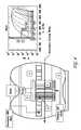
- FIG. 3illustrates an exemplary supersonic cooling system 300 in accordance with an embodiment of the present invention.
- the supersonic cooling system 300does not need to compress a gas as otherwise occurs at compressor ( 110 ) in a prior art vapor compression system 100 like that shown in FIG. 1 .
- Supersonic cooling system 300operates by pumping liquid. Because supersonic cooling system 300 pumps liquid, the compression system 300 does not require the use a condenser ( 120 ) as does the prior art compression system 100 of FIG. 1 .
- Compression system 300instead utilizes a compression wave.
- the evaporator of compression system 300operates in the critical flow regime where the pressure in an evaporator tube will remain almost constant and then ‘jump’ or ‘shock up’ to the ambient pressure.
- the supersonic cooling system 300 of FIG. 3recognizes a certain degree of efficiency in that the pump ( 320 ) of the system 300 does not (nor does it need to) draw as much power as the compressor ( 110 ) in a prior art compression system 100 like that shown in FIG. 1 .
- a compression system designed according to an embodiment of the presently disclosed inventionmay recognize exponential pumping efficiencies. For example, where a prior art compression system ( 100 ) may require 1.75-2.5 kilowatts for every 5 kilowatts of cooling power, an system ( 300 ) like that illustrated in FIG. 3 may pump liquid from 14.7 to 120 PSI with the pump drawing power at approximately 500 W. As a result of these efficiencies, system 300 may utilize many working fluids, including but not limited to water.
- the supersonic cooling system 300 of FIG. 3includes housing 310 .
- Housing 310 of FIG. 3is akin to that of a pumpkin.
- the particular shape or other design of housing 310may be a matter of aesthetics with respect to where or how the system 300 is installed relative a facility or coupled equipment or machinery.
- housing 310encloses pump 330 , evaporator 350 , and accessory equipment or flow paths corresponding to the same (e.g., pump inlet 340 and evaporator tube 360 ). Housing 310 also maintains (internally) the cooling liquid to be used by the system 300 .
- Housing 310may also encompass a secondary heat exchanger (not illustrated).
- a secondary heat exchangermay be excluded from being contained within the housing 310 and system 300 .
- the surface area of the system 300that is, the housing 310 —may be utilized in a cooling process through forced convection on the external surface of the housing 310 .
- Pump 330may be powered by a motor 320 , which is external to the system 300 and located outside the housing 310 in FIG. 3 .
- Motor 320may alternatively be contained within the housing 310 of system 300 .
- Motor 320may drive the pump 330 of FIG. 3 through a rotor drive shaft with a corresponding bearing and seal or magnetic induction, whereby penetration of the housing 310 is not required.
- Other motor designsmay be utilized with respect to motor 320 and corresponding pump 330 including synchronous, alternating (AC), and direct current (DC) motors.
- system 300Other electric motors that may be used with system 300 include induction motors; brushed and brushless DC motors; stepper, linear, unipolar, and reluctance motors; and ball bearing, homopolar, piezoelectric, ultrasonic, and electrostatic motors.
- Pump 330establishes circulation of a liquid through the interior fluid flow paths of system 300 and that are otherwise contained within housing 310 .
- Pump 330may circulate fluid throughout system 300 through use of vortex flow rings.
- Vortex ringsoperate as energy reservoirs whereby added energy is stored in the vortex ring.
- the progressive introduction of energy to a vortex ring via pump 330causes the corresponding ring vortex to function at a level such that energy lost through dissipation corresponds to energy being input.
- Pump 330also operates to raise the pressure of a liquid being used by system 300 from, for example, 20 PSI to 100 PSI or more.
- Pump inlet 340introduces a liquid to be used in cooling and otherwise resident in system 300 (and contained within housing 310 ) into pump 330 .
- Fluid temperaturemay, at this point in the system 300 , be approximately 95 F.
- the fluid introduced to pump 330 by inlet 340traverses a primary flow path to nozzle/evaporator 350 .
- Evaporator 350induces a pressure drop (e.g., to approximately 5.5 PSI) and phase change that results in a low temperature.
- the cooling fluidfurther ‘boils off’ at evaporator 350 , whereby the resident liquid may be used as a coolant.
- the liquid coolantmay be water cooled to 35-45 F (approximately 37 F as illustrated in FIG. 3 ).
- the system 300specifically evaporator 350
- the nozzle/evaporator 350 and evaporator tube 360may be integrated and/or collectively referred to as an evaporator.
- the coolant fluid of system 300may be cooled at a heat exchanger to assist in dissipating heat once the coolant has absorbed the same (approximately 90-100 F after having exited evaporator 350 ).
- the housing 310 of the system 300may be used to cool via forced convection.
- FIG. 4illustrates performance of a supersonic cooling system like that illustrated in FIG. 3 .
- FIG. 5illustrates a method of operation 500 for the supersonic cooling system 300 of FIG. 3 .
- a gear pump 330raises the pressure of a liquid.
- the pressuremay, for example, be raised from 20 PSI to in excess of 100 PSI.
- fluidflows through the nozzle/evaporator 350 . Pressure drop and phase change result in a lower temperature in the tube. Fluid is boiled off in step 530 .
- Critical flow ratewhich is the maximum flow rate that can be attained by a compressible fluid as that fluid passes from a high pressure region to a low pressure region (i.e., the critical flow regime), allows for a compression wave to be established and utilized in the critical flow regime.
- Critical flowoccurs when the velocity of the fluid is greater or equal to the speed of sound in the fluid.
- the pressure in the channelwill not be influenced by the exit pressure and at the channel exit, the fluid will ‘shock up’ to the ambient condition. In critical flow the fluid will also stay at the low pressure and temperature corresponding to the saturation pressures.
- a secondary heat exchangermay be used in optional step 550 . Secondary cooling may also occur via convection on the surface of the system 300 housing 310 .
Landscapes
- Engineering & Computer Science (AREA)
- Mechanical Engineering (AREA)
- General Engineering & Computer Science (AREA)
- Physics & Mathematics (AREA)
- Thermal Sciences (AREA)
- Cooling Or The Like Of Electrical Apparatus (AREA)
- Structures Of Non-Positive Displacement Pumps (AREA)
- Devices That Are Associated With Refrigeration Equipment (AREA)
Abstract
Description
Claims (19)
Priority Applications (1)
| Application Number | Priority Date | Filing Date | Title |
|---|---|---|---|
| US12/961,342US8353169B2 (en) | 2009-03-25 | 2010-12-06 | Supersonic cooling system |
Applications Claiming Priority (4)
| Application Number | Priority Date | Filing Date | Title |
|---|---|---|---|
| US16343809P | 2009-03-25 | 2009-03-25 | |
| US22855709P | 2009-07-25 | 2009-07-25 | |
| US12/732,171US8333080B2 (en) | 2009-03-25 | 2010-03-25 | Supersonic cooling system |
| US12/961,342US8353169B2 (en) | 2009-03-25 | 2010-12-06 | Supersonic cooling system |
Related Parent Applications (1)
| Application Number | Title | Priority Date | Filing Date |
|---|---|---|---|
| US12/732,171ContinuationUS8333080B2 (en) | 2009-03-25 | 2010-03-25 | Supersonic cooling system |
Publications (2)
| Publication Number | Publication Date |
|---|---|
| US20110088878A1 US20110088878A1 (en) | 2011-04-21 |
| US8353169B2true US8353169B2 (en) | 2013-01-15 |
Family
ID=42781533
Family Applications (5)
| Application Number | Title | Priority Date | Filing Date |
|---|---|---|---|
| US12/732,171Expired - Fee RelatedUS8333080B2 (en) | 2009-03-25 | 2010-03-25 | Supersonic cooling system |
| US12/961,342Expired - Fee RelatedUS8353169B2 (en) | 2009-03-25 | 2010-12-06 | Supersonic cooling system |
| US12/960,979Expired - Fee RelatedUS8353168B2 (en) | 2009-03-25 | 2010-12-06 | Thermodynamic cycle for cooling a working fluid |
| US12/961,015AbandonedUS20110094249A1 (en) | 2009-03-25 | 2010-12-06 | Pressure Shock-Induced Cooling Cycle |
| US14/079,970AbandonedUS20140174113A1 (en) | 2009-03-25 | 2013-11-14 | Pressure shock-induced cooling cycle |
Family Applications Before (1)
| Application Number | Title | Priority Date | Filing Date |
|---|---|---|---|
| US12/732,171Expired - Fee RelatedUS8333080B2 (en) | 2009-03-25 | 2010-03-25 | Supersonic cooling system |
Family Applications After (3)
| Application Number | Title | Priority Date | Filing Date |
|---|---|---|---|
| US12/960,979Expired - Fee RelatedUS8353168B2 (en) | 2009-03-25 | 2010-12-06 | Thermodynamic cycle for cooling a working fluid |
| US12/961,015AbandonedUS20110094249A1 (en) | 2009-03-25 | 2010-12-06 | Pressure Shock-Induced Cooling Cycle |
| US14/079,970AbandonedUS20140174113A1 (en) | 2009-03-25 | 2013-11-14 | Pressure shock-induced cooling cycle |
Country Status (10)
| Country | Link |
|---|---|
| US (5) | US8333080B2 (en) |
| EP (1) | EP2411744A1 (en) |
| JP (1) | JP2012522204A (en) |
| KR (1) | KR20120093060A (en) |
| CN (1) | CN102449413A (en) |
| AU (1) | AU2010229821A1 (en) |
| BR (1) | BRPI1012630A2 (en) |
| GB (2) | GB2472965A (en) |
| IL (1) | IL215350A0 (en) |
| WO (1) | WO2010111560A1 (en) |
Cited By (3)
| Publication number | Priority date | Publication date | Assignee | Title |
|---|---|---|---|---|
| US20110113792A1 (en)* | 2009-09-04 | 2011-05-19 | Jayden David Harman | Heat Exchange and Cooling Systems |
| US20120234027A1 (en)* | 2011-03-15 | 2012-09-20 | David Halt | Supersonic Cooling Nozzle with Airfoils |
| US8820114B2 (en) | 2009-03-25 | 2014-09-02 | Pax Scientific, Inc. | Cooling of heat intensive systems |
Families Citing this family (19)
| Publication number | Priority date | Publication date | Assignee | Title |
|---|---|---|---|---|
| US10683865B2 (en) | 2006-02-14 | 2020-06-16 | Air Squared, Inc. | Scroll type device incorporating spinning or co-rotating scrolls |
| US20110048048A1 (en)* | 2009-03-25 | 2011-03-03 | Thomas Gielda | Personal Cooling System |
| US8505322B2 (en)* | 2009-03-25 | 2013-08-13 | Pax Scientific, Inc. | Battery cooling |
| AU2010229821A1 (en) | 2009-03-25 | 2011-11-17 | Caitin, Inc. | Supersonic cooling system |
| US20110048062A1 (en)* | 2009-03-25 | 2011-03-03 | Thomas Gielda | Portable Cooling Unit |
| US20110030390A1 (en)* | 2009-04-02 | 2011-02-10 | Serguei Charamko | Vortex Tube |
| US20110051549A1 (en)* | 2009-07-25 | 2011-03-03 | Kristian Debus | Nucleation Ring for a Central Insert |
| US11047389B2 (en) | 2010-04-16 | 2021-06-29 | Air Squared, Inc. | Multi-stage scroll vacuum pumps and related scroll devices |
| WO2012018627A1 (en)* | 2010-07-26 | 2012-02-09 | Caitin Inc. | Supersonic cooling nozzle inlet |
| US20130232975A1 (en) | 2011-08-09 | 2013-09-12 | Robert W. Saffer | Compact energy cycle construction utilizing some combination of a scroll type expander, pump, and compressor for operating according to a rankine, an organic rankine, heat pump, or combined organic rankine and heat pump cycle |
| US10508543B2 (en) | 2015-05-07 | 2019-12-17 | Air Squared, Inc. | Scroll device having a pressure plate |
| US10865793B2 (en) | 2016-12-06 | 2020-12-15 | Air Squared, Inc. | Scroll type device having liquid cooling through idler shafts |
| WO2019212598A1 (en) | 2018-05-04 | 2019-11-07 | Air Squared, Inc. | Liquid cooling of fixed and orbiting scroll compressor, expander or vacuum pump |
| US20200025199A1 (en) | 2018-07-17 | 2020-01-23 | Air Squared, Inc. | Dual drive co-rotating spinning scroll compressor or expander |
| US11067080B2 (en) | 2018-07-17 | 2021-07-20 | Air Squared, Inc. | Low cost scroll compressor or vacuum pump |
| US11530703B2 (en) | 2018-07-18 | 2022-12-20 | Air Squared, Inc. | Orbiting scroll device lubrication |
| US11473572B2 (en) | 2019-06-25 | 2022-10-18 | Air Squared, Inc. | Aftercooler for cooling compressed working fluid |
| US11898557B2 (en) | 2020-11-30 | 2024-02-13 | Air Squared, Inc. | Liquid cooling of a scroll type compressor with liquid supply through the crankshaft |
| US11885328B2 (en) | 2021-07-19 | 2024-01-30 | Air Squared, Inc. | Scroll device with an integrated cooling loop |
Citations (93)
| Publication number | Priority date | Publication date | Assignee | Title |
|---|---|---|---|---|
| US1860447A (en) | 1928-07-21 | 1932-05-31 | York Ice Machinery Corp | Refrigeration |
| US2116480A (en) | 1936-01-17 | 1938-05-03 | Climax Machinery Company | Method and apparatus for conditioning air |
| US2928779A (en) | 1954-08-16 | 1960-03-15 | Jordan T Weills | Neutronic reactor construction and operation |
| US3228848A (en) | 1959-10-29 | 1966-01-11 | Socony Mobil Oil Co Inc | Method and contact material for chemical conversion in presence of nuclear fission fragments |
| US3425486A (en) | 1965-10-28 | 1969-02-04 | Aviat Uk | Garments for controlling the temperature of the body |
| US3510266A (en) | 1967-03-29 | 1970-05-05 | Merck & Co Inc | Production of crystals in a fluidized bed with ultrasonic vibrations |
| US3548589A (en) | 1968-01-19 | 1970-12-22 | Atomic Energy Authority Uk | Heat engines |
| US3552120A (en) | 1969-03-05 | 1971-01-05 | Research Corp | Stirling cycle type thermal device |
| US3621667A (en)* | 1969-03-24 | 1971-11-23 | American Gas Ass The | Cooling apparatus and process |
| US3866433A (en)* | 1973-09-12 | 1975-02-18 | Jeffreys George C | Auxiliary refrigeration power means |
| US4031712A (en) | 1975-12-04 | 1977-06-28 | The University Of Delaware | Combined absorption and vapor-compression refrigeration system |
| US4044558A (en) | 1974-08-09 | 1977-08-30 | New Process Industries, Inc. | Thermal oscillator |
| US4057962A (en) | 1976-12-06 | 1977-11-15 | Ford Motor Company | Device for decreasing the start-up time for stirling engines |
| US4089187A (en) | 1975-06-23 | 1978-05-16 | General Electric Company | Condenser-air flow system of a household refrigerator |
| US4201263A (en) | 1978-09-19 | 1980-05-06 | Anderson James H | Refrigerant evaporator |
| US4333796A (en) | 1978-05-19 | 1982-06-08 | Flynn Hugh G | Method of generating energy by acoustically induced cavitation fusion and reactor therefor |
| US4442675A (en)* | 1981-05-11 | 1984-04-17 | Soma Kurtis | Method for thermodynamic cycle |
| JPS60175980A (en) | 1984-01-12 | 1985-09-10 | ドリ ヘルシユガル | Cooling method |
| US4858155A (en) | 1985-12-24 | 1989-08-15 | Beckman Instruments, Inc. | Reaction temperature control system |
| US4998415A (en) | 1989-10-30 | 1991-03-12 | Larsen John D | Body cooling apparatus |
| US5074759A (en) | 1990-03-14 | 1991-12-24 | Cossairt Keith R | Fluid dynamic pump |
| US5083429A (en) | 1988-07-08 | 1992-01-28 | Gergely Veres | Method of and compression tube for increasing pressure of a flowing gaseous medium, and power machine applying the compression tube |
| US5205648A (en) | 1990-09-06 | 1993-04-27 | Transsonic Uberschall-Anlagen Gmbh | Method and device for acting upon fluids by means of a shock wave |
| US5317905A (en) | 1992-10-05 | 1994-06-07 | Johnson H James | Refrigeration system |
| US5338113A (en) | 1990-09-06 | 1994-08-16 | Transsonic Uberschall-Anlagen Gmbh | Method and device for pressure jumps in two-phase mixtures |
| US5353602A (en)* | 1993-03-25 | 1994-10-11 | Calmac Manufacturing Corporation | Non-steady-state self-regulating intermittent flow thermodynamic system |
| US5544961A (en) | 1992-02-11 | 1996-08-13 | April Dynamics Industries Ltd. | Two-phase supersonic flow system |
| US5659173A (en) | 1994-02-23 | 1997-08-19 | The Regents Of The University Of California | Converting acoustic energy into useful other energy forms |
| US5810037A (en) | 1994-07-22 | 1998-09-22 | Daido Metal Company Ltd. | Ultrasonic treatment apparatus |
| US5980698A (en) | 1994-08-19 | 1999-11-09 | Valery Grigorievich Tsegelsky | Method for vacuum distillation of a liquid product and an equipment for performing thereof |
| US6105382A (en) | 1999-03-29 | 2000-08-22 | The United States Of America As Represented By The Secretary Of The Navy | Chest mounted armored microclimate conditioned air device |
| US6170289B1 (en)* | 1999-06-18 | 2001-01-09 | General Electric Company | Noise suppressing refrigeration jumper tube |
| US6190498B1 (en)* | 1999-02-01 | 2001-02-20 | Slimline Mfg. Ltd. | Evaporator |
| EP1080648A2 (en) | 1999-09-06 | 2001-03-07 | Fisher & Paykel Limited | Personal cooling system |
| US6280578B1 (en) | 1997-04-21 | 2001-08-28 | Evgueni D. Petroukhine | Operation process of a pumping-ejection stand for distilling liquid products |
| JP2002130770A (en) | 2000-10-30 | 2002-05-09 | Mitsubishi Electric Corp | Refrigeration cycle apparatus and control method thereof |
| US6398918B1 (en) | 1997-09-04 | 2002-06-04 | Evgueni D. Petroukhine | Method for distilling a mixture containing a plurality of components and apparatus for realizing the same |
| US20020090047A1 (en) | 1991-10-25 | 2002-07-11 | Roger Stringham | Apparatus for producing ecologically clean energy |
| US20020177035A1 (en) | 2001-05-23 | 2002-11-28 | Alcatel | Thermal management blanketing and jacketing for battery system modules |
| JP2003021410A (en) | 2001-07-04 | 2003-01-24 | Japan Climate Systems Corp | Vehicle air conditioner |
| JP2003034135A (en) | 2001-07-25 | 2003-02-04 | Japan Climate Systems Corp | Air conditioning system for vehicle |
| US6604376B1 (en) | 1999-01-08 | 2003-08-12 | Victor M. Demarco | Heat pump using treated water effluent |
| US6655165B1 (en) | 2002-12-19 | 2003-12-02 | Nissan Technical Center North America, Inc. | Air conditioner with power recovery device having a sound suppression device |
| US6719817B1 (en) | 2003-06-17 | 2004-04-13 | Daniel J Marin | Cavitation hydrogen generator |
| US6739141B1 (en) | 2003-02-12 | 2004-05-25 | Carrier Corporation | Supercritical pressure regulation of vapor compression system by use of gas cooler fluid pumping device |
| US20040172966A1 (en) | 2003-03-05 | 2004-09-09 | Yukikatsu Ozaki | Ejector with tapered nozzle and tapered needle |
| US6835484B2 (en) | 2002-07-09 | 2004-12-28 | General Motors Corporation | Supersonic vapor compression and heat rejection cycle |
| US6889754B2 (en) | 2000-06-30 | 2005-05-10 | Swales & Associates, Inc. | Phase control in the capillary evaporators |
| JP2005240689A (en) | 2004-02-26 | 2005-09-08 | Kashiyama Kogyo Kk | Pump |
| US20060018420A1 (en) | 1999-11-24 | 2006-01-26 | Impulse Devices, Inc. | Heat exchange system for a cavitation chamber |
| US20060032625A1 (en) | 2002-09-28 | 2006-02-16 | Angelis Walter G | Arrangement and method for removing heat from a component which is to be cooled |
| US7004240B1 (en) | 2002-06-24 | 2006-02-28 | Swales & Associates, Inc. | Heat transport system |
| WO2006054408A1 (en) | 2004-11-17 | 2006-05-26 | Sanyo Electric Co., Ltd. | Distillation apparatus for dry cleaner |
| US20060191049A1 (en) | 2004-05-11 | 2006-08-31 | William Elkins | Wearable personal cooling and hydration system |
| US7131294B2 (en) | 2004-01-13 | 2006-11-07 | Tecumseh Products Company | Method and apparatus for control of carbon dioxide gas cooler pressure by use of a capillary tube |
| US20070028646A1 (en) | 2005-08-02 | 2007-02-08 | Denso Corporation | Ejector refrigeration cycle |
| US7178353B2 (en) | 2004-02-19 | 2007-02-20 | Advanced Thermal Sciences Corp. | Thermal control system and method |
| US7251889B2 (en) | 2000-06-30 | 2007-08-07 | Swales & Associates, Inc. | Manufacture of a heat transfer system |
| US20070199333A1 (en) | 2006-02-27 | 2007-08-30 | Robert Windisch | Thermoelectric fluid heat exchange system |
| US20070271939A1 (en) | 2003-12-25 | 2007-11-29 | Seft Development Laboratory Co., Ltd. | Air-Conditioning Garment |
| US20080006051A1 (en) | 2006-07-06 | 2008-01-10 | Mark Johnson | Portable cooler |
| US20080057382A1 (en) | 2004-12-14 | 2008-03-06 | Tadao Kimura | Battery Pack |
| US20080105315A1 (en) | 2006-09-25 | 2008-05-08 | Transcanada Pipelines Limited | Tandem supersonic ejectors |
| US7381241B2 (en) | 1999-11-24 | 2008-06-03 | Impulse Devices, Inc. | Degassing procedure for a cavitation chamber |
| US7387093B2 (en) | 2006-10-02 | 2008-06-17 | James Scott Hacsi | Internal combustion engine with sidewall combustion chamber and method |
| US7387660B2 (en) | 1999-11-24 | 2008-06-17 | Impulse Devices, Inc., | Degassing procedure for a cavitation chamber |
| US7448790B2 (en) | 1999-11-24 | 2008-11-11 | Impulse Devices, Inc. | Cavitation fluid circulatory system for a cavitation chamber |
| US20080292948A1 (en) | 2007-05-23 | 2008-11-27 | Ajith Kuttannair Kumar | Battery cooling system and methods of cooling |
| WO2009070728A1 (en) | 2007-11-27 | 2009-06-04 | The Curators Of The University Of Missouri | Thermally driven heat pump for heating and cooling |
| US7549461B2 (en) | 2000-06-30 | 2009-06-23 | Alliant Techsystems Inc. | Thermal management system |
| JP2009221883A (en) | 2008-03-13 | 2009-10-01 | Denso Corp | Ejector device and vapor compression refrigeration cycle using ejector device |
| WO2009123674A2 (en) | 2008-02-28 | 2009-10-08 | Greencentaire, Llc | Cooling unit |
| US20090272128A1 (en) | 2008-05-02 | 2009-11-05 | Kysor Industrial Corporation | Cascade cooling system with intercycle cooling |
| US20090293513A1 (en) | 2008-05-28 | 2009-12-03 | Sullivan Shaun E | Machines and Methods for Removing Water From Air |
| US7654095B2 (en) | 2007-06-06 | 2010-02-02 | Greencentaire, Llc | Energy transfer apparatus and methods |
| US7656808B2 (en) | 2003-01-15 | 2010-02-02 | At&T Intellectual Property I, Lp | Web based capacity management (WBCM) system |
| US20100043633A1 (en) | 2006-05-05 | 2010-02-25 | Separation Design Group, Llc | Sorption method, device, and system |
| WO2010042467A2 (en) | 2008-10-10 | 2010-04-15 | Spin Energy Corporation | Power-generator fan apparatus, duct assembly, building construction, and methods of use |
| US7708053B2 (en) | 2000-06-30 | 2010-05-04 | Alliant Techsystems Inc. | Heat transfer system |
| US20100126212A1 (en) | 2008-08-14 | 2010-05-27 | May Wayne A | Binary fluid ejector and method of use |
| US7796389B2 (en) | 2008-11-26 | 2010-09-14 | General Electric Company | Method and apparatus for cooling electronics |
| US20100287954A1 (en) | 2009-03-25 | 2010-11-18 | Jayden Harman | Supersonic Cooling System |
| US20110030390A1 (en) | 2009-04-02 | 2011-02-10 | Serguei Charamko | Vortex Tube |
| US20110048048A1 (en) | 2009-03-25 | 2011-03-03 | Thomas Gielda | Personal Cooling System |
| US20110048066A1 (en) | 2009-03-25 | 2011-03-03 | Thomas Gielda | Battery Cooling |
| US20110051549A1 (en) | 2009-07-25 | 2011-03-03 | Kristian Debus | Nucleation Ring for a Central Insert |
| US20110048062A1 (en) | 2009-03-25 | 2011-03-03 | Thomas Gielda | Portable Cooling Unit |
| US20110117511A1 (en) | 2009-09-04 | 2011-05-19 | Jayden David Harman | Heating and Cooling of Working Fluids |
| US20120000631A1 (en) | 2009-03-25 | 2012-01-05 | Serguei Charamko | Cooling of Heat Intensive Systems |
| US20120118538A1 (en) | 2010-11-12 | 2012-05-17 | Thomas Gielda | Pump-Less Cooling |
| US20120205080A1 (en) | 2011-02-15 | 2012-08-16 | Kristian Debus | Pump-Less Cooling Using a Rotating Disk |
| US20120260673A1 (en) | 2011-04-14 | 2012-10-18 | Serguei Charamko | Cooling system utilizing a reciprocating piston |
| US20120260676A1 (en) | 2011-04-18 | 2012-10-18 | Serguei Charamko | Cooling system utilizing a conical body |
Family Cites Families (11)
| Publication number | Priority date | Publication date | Assignee | Title |
|---|---|---|---|---|
| US442675A (en)* | 1890-12-16 | Curtis n | ||
| US433796A (en)* | 1890-08-05 | Heel-beading machine | ||
| CR5278A (en)* | 1995-03-24 | 1996-07-04 | Lilly Co Eli | ORAL FORMULATION OF 2-METHYL-THENO-BENZODIACEPINE |
| US6466668B1 (en)* | 1998-01-28 | 2002-10-15 | Hitachi, Ltd. | IC card equipped with elliptical curve encryption processing facility |
| FR2804159B1 (en)* | 2000-01-20 | 2002-09-06 | Bernard Simon | SEMI-RIGID BLADES FOR FLEXIBLE CURTAIN HANDLING DOOR |
| US20020130770A1 (en)* | 2000-12-29 | 2002-09-19 | Dennis Keyworth | Object sensor with integrally molded housing and method for making same |
| EP1411739B1 (en)* | 2002-10-15 | 2006-07-05 | Lucent Technologies Inc. | A method of selecting cells of base stations for soft-handover connection, and a network for mobile telecommunications |
| US8046727B2 (en)* | 2007-09-12 | 2011-10-25 | Neal Solomon | IP cores in reconfigurable three dimensional integrated circuits |
| US8247044B2 (en)* | 2007-11-08 | 2012-08-21 | Eastman Kodak Company | Inkjet recording element |
| US20100042467A1 (en)* | 2008-08-14 | 2010-02-18 | Reza Bundy | Method and Apparatus for Implementing an Automatic Marketing System |
| JP5939731B2 (en)* | 2009-07-10 | 2016-06-22 | キヤノン株式会社 | Image forming apparatus |
- 2010
- 2010-03-25AUAU2010229821Apatent/AU2010229821A1/ennot_activeAbandoned
- 2010-03-25GBGB1021892Apatent/GB2472965A/ennot_activeWithdrawn
- 2010-03-25GBGB1021925.1Apatent/GB2473981B/ennot_activeExpired - Fee Related
- 2010-03-25KRKR1020117025259Apatent/KR20120093060A/ennot_activeWithdrawn
- 2010-03-25USUS12/732,171patent/US8333080B2/ennot_activeExpired - Fee Related
- 2010-03-25BRBRPI1012630Apatent/BRPI1012630A2/ennot_activeIP Right Cessation
- 2010-03-25EPEP10756891Apatent/EP2411744A1/ennot_activeWithdrawn
- 2010-03-25JPJP2012502274Apatent/JP2012522204A/enactivePending
- 2010-03-25CNCN2010800229947Apatent/CN102449413A/enactivePending
- 2010-03-25WOPCT/US2010/028761patent/WO2010111560A1/enactiveApplication Filing
- 2010-12-06USUS12/961,342patent/US8353169B2/ennot_activeExpired - Fee Related
- 2010-12-06USUS12/960,979patent/US8353168B2/ennot_activeExpired - Fee Related
- 2010-12-06USUS12/961,015patent/US20110094249A1/ennot_activeAbandoned
- 2011
- 2011-09-25ILIL215350Apatent/IL215350A0/enunknown
- 2013
- 2013-11-14USUS14/079,970patent/US20140174113A1/ennot_activeAbandoned
Patent Citations (110)
| Publication number | Priority date | Publication date | Assignee | Title |
|---|---|---|---|---|
| US1860447A (en) | 1928-07-21 | 1932-05-31 | York Ice Machinery Corp | Refrigeration |
| US2116480A (en) | 1936-01-17 | 1938-05-03 | Climax Machinery Company | Method and apparatus for conditioning air |
| US2928779A (en) | 1954-08-16 | 1960-03-15 | Jordan T Weills | Neutronic reactor construction and operation |
| US3228848A (en) | 1959-10-29 | 1966-01-11 | Socony Mobil Oil Co Inc | Method and contact material for chemical conversion in presence of nuclear fission fragments |
| US3425486A (en) | 1965-10-28 | 1969-02-04 | Aviat Uk | Garments for controlling the temperature of the body |
| US3510266A (en) | 1967-03-29 | 1970-05-05 | Merck & Co Inc | Production of crystals in a fluidized bed with ultrasonic vibrations |
| US3548589A (en) | 1968-01-19 | 1970-12-22 | Atomic Energy Authority Uk | Heat engines |
| US3552120A (en) | 1969-03-05 | 1971-01-05 | Research Corp | Stirling cycle type thermal device |
| US3621667A (en)* | 1969-03-24 | 1971-11-23 | American Gas Ass The | Cooling apparatus and process |
| US3866433A (en)* | 1973-09-12 | 1975-02-18 | Jeffreys George C | Auxiliary refrigeration power means |
| US4044558A (en) | 1974-08-09 | 1977-08-30 | New Process Industries, Inc. | Thermal oscillator |
| US4089187A (en) | 1975-06-23 | 1978-05-16 | General Electric Company | Condenser-air flow system of a household refrigerator |
| US4031712A (en) | 1975-12-04 | 1977-06-28 | The University Of Delaware | Combined absorption and vapor-compression refrigeration system |
| US4057962A (en) | 1976-12-06 | 1977-11-15 | Ford Motor Company | Device for decreasing the start-up time for stirling engines |
| US4333796A (en) | 1978-05-19 | 1982-06-08 | Flynn Hugh G | Method of generating energy by acoustically induced cavitation fusion and reactor therefor |
| US4201263A (en) | 1978-09-19 | 1980-05-06 | Anderson James H | Refrigerant evaporator |
| US4442675A (en)* | 1981-05-11 | 1984-04-17 | Soma Kurtis | Method for thermodynamic cycle |
| JPS60175980A (en) | 1984-01-12 | 1985-09-10 | ドリ ヘルシユガル | Cooling method |
| US4858155A (en) | 1985-12-24 | 1989-08-15 | Beckman Instruments, Inc. | Reaction temperature control system |
| US5083429A (en) | 1988-07-08 | 1992-01-28 | Gergely Veres | Method of and compression tube for increasing pressure of a flowing gaseous medium, and power machine applying the compression tube |
| US4998415A (en) | 1989-10-30 | 1991-03-12 | Larsen John D | Body cooling apparatus |
| US5074759A (en) | 1990-03-14 | 1991-12-24 | Cossairt Keith R | Fluid dynamic pump |
| US5205648A (en) | 1990-09-06 | 1993-04-27 | Transsonic Uberschall-Anlagen Gmbh | Method and device for acting upon fluids by means of a shock wave |
| US5275486A (en) | 1990-09-06 | 1994-01-04 | Transsonic Uberschall-Anlagen Gmbh | Device for acting upon fluids by means of a shock wave |
| US5338113A (en) | 1990-09-06 | 1994-08-16 | Transsonic Uberschall-Anlagen Gmbh | Method and device for pressure jumps in two-phase mixtures |
| US20020090047A1 (en) | 1991-10-25 | 2002-07-11 | Roger Stringham | Apparatus for producing ecologically clean energy |
| US5544961A (en) | 1992-02-11 | 1996-08-13 | April Dynamics Industries Ltd. | Two-phase supersonic flow system |
| US5317905A (en) | 1992-10-05 | 1994-06-07 | Johnson H James | Refrigeration system |
| US5353602A (en)* | 1993-03-25 | 1994-10-11 | Calmac Manufacturing Corporation | Non-steady-state self-regulating intermittent flow thermodynamic system |
| US5659173A (en) | 1994-02-23 | 1997-08-19 | The Regents Of The University Of California | Converting acoustic energy into useful other energy forms |
| US5810037A (en) | 1994-07-22 | 1998-09-22 | Daido Metal Company Ltd. | Ultrasonic treatment apparatus |
| US5980698A (en) | 1994-08-19 | 1999-11-09 | Valery Grigorievich Tsegelsky | Method for vacuum distillation of a liquid product and an equipment for performing thereof |
| US6280578B1 (en) | 1997-04-21 | 2001-08-28 | Evgueni D. Petroukhine | Operation process of a pumping-ejection stand for distilling liquid products |
| US6398918B1 (en) | 1997-09-04 | 2002-06-04 | Evgueni D. Petroukhine | Method for distilling a mixture containing a plurality of components and apparatus for realizing the same |
| US6604376B1 (en) | 1999-01-08 | 2003-08-12 | Victor M. Demarco | Heat pump using treated water effluent |
| US6190498B1 (en)* | 1999-02-01 | 2001-02-20 | Slimline Mfg. Ltd. | Evaporator |
| US6105382A (en) | 1999-03-29 | 2000-08-22 | The United States Of America As Represented By The Secretary Of The Navy | Chest mounted armored microclimate conditioned air device |
| US6170289B1 (en)* | 1999-06-18 | 2001-01-09 | General Electric Company | Noise suppressing refrigeration jumper tube |
| EP1080648A2 (en) | 1999-09-06 | 2001-03-07 | Fisher & Paykel Limited | Personal cooling system |
| US7448790B2 (en) | 1999-11-24 | 2008-11-11 | Impulse Devices, Inc. | Cavitation fluid circulatory system for a cavitation chamber |
| US20060018420A1 (en) | 1999-11-24 | 2006-01-26 | Impulse Devices, Inc. | Heat exchange system for a cavitation chamber |
| US7387660B2 (en) | 1999-11-24 | 2008-06-17 | Impulse Devices, Inc., | Degassing procedure for a cavitation chamber |
| US7381241B2 (en) | 1999-11-24 | 2008-06-03 | Impulse Devices, Inc. | Degassing procedure for a cavitation chamber |
| US20060018419A1 (en) | 1999-11-24 | 2006-01-26 | Impulse Devices, Inc. | Heat exchange system for a cavitation chamber |
| US7708053B2 (en) | 2000-06-30 | 2010-05-04 | Alliant Techsystems Inc. | Heat transfer system |
| US7549461B2 (en) | 2000-06-30 | 2009-06-23 | Alliant Techsystems Inc. | Thermal management system |
| US7251889B2 (en) | 2000-06-30 | 2007-08-07 | Swales & Associates, Inc. | Manufacture of a heat transfer system |
| US6889754B2 (en) | 2000-06-30 | 2005-05-10 | Swales & Associates, Inc. | Phase control in the capillary evaporators |
| JP2002130770A (en) | 2000-10-30 | 2002-05-09 | Mitsubishi Electric Corp | Refrigeration cycle apparatus and control method thereof |
| US20020177035A1 (en) | 2001-05-23 | 2002-11-28 | Alcatel | Thermal management blanketing and jacketing for battery system modules |
| JP2003021410A (en) | 2001-07-04 | 2003-01-24 | Japan Climate Systems Corp | Vehicle air conditioner |
| JP2003034135A (en) | 2001-07-25 | 2003-02-04 | Japan Climate Systems Corp | Air conditioning system for vehicle |
| US7004240B1 (en) | 2002-06-24 | 2006-02-28 | Swales & Associates, Inc. | Heat transport system |
| US20080277098A1 (en) | 2002-07-09 | 2008-11-13 | General Motors Corporation | Supersonic vapor compression and heat rejection cycle |
| US20050048339A1 (en)* | 2002-07-09 | 2005-03-03 | Fly Gerald W. | Supersonic vapor compression and heat rejection cycle |
| US7399545B2 (en) | 2002-07-09 | 2008-07-15 | General Motors Corporation | Supersonic vapor compression and heat rejection cycle |
| US6835484B2 (en) | 2002-07-09 | 2004-12-28 | General Motors Corporation | Supersonic vapor compression and heat rejection cycle |
| US20060032625A1 (en) | 2002-09-28 | 2006-02-16 | Angelis Walter G | Arrangement and method for removing heat from a component which is to be cooled |
| US6655165B1 (en) | 2002-12-19 | 2003-12-02 | Nissan Technical Center North America, Inc. | Air conditioner with power recovery device having a sound suppression device |
| US7656808B2 (en) | 2003-01-15 | 2010-02-02 | At&T Intellectual Property I, Lp | Web based capacity management (WBCM) system |
| US6739141B1 (en) | 2003-02-12 | 2004-05-25 | Carrier Corporation | Supercritical pressure regulation of vapor compression system by use of gas cooler fluid pumping device |
| WO2004072567A2 (en) | 2003-02-12 | 2004-08-26 | Carrier Corporation | Supercritical pressure regulation of vapor compression system |
| US20040172966A1 (en) | 2003-03-05 | 2004-09-09 | Yukikatsu Ozaki | Ejector with tapered nozzle and tapered needle |
| US6719817B1 (en) | 2003-06-17 | 2004-04-13 | Daniel J Marin | Cavitation hydrogen generator |
| US20070271939A1 (en) | 2003-12-25 | 2007-11-29 | Seft Development Laboratory Co., Ltd. | Air-Conditioning Garment |
| US7131294B2 (en) | 2004-01-13 | 2006-11-07 | Tecumseh Products Company | Method and apparatus for control of carbon dioxide gas cooler pressure by use of a capillary tube |
| US7721569B2 (en) | 2004-01-13 | 2010-05-25 | Tecumseh Products Company | Method and apparatus for control of carbon dioxide gas cooler pressure by use of a capillary tube |
| US7178353B2 (en) | 2004-02-19 | 2007-02-20 | Advanced Thermal Sciences Corp. | Thermal control system and method |
| US7415835B2 (en) | 2004-02-19 | 2008-08-26 | Advanced Thermal Sciences Corp. | Thermal control system and method |
| US7765820B2 (en) | 2004-02-19 | 2010-08-03 | Advanced Thermal Sciences, Corp. | Thermal control system and method |
| JP2005240689A (en) | 2004-02-26 | 2005-09-08 | Kashiyama Kogyo Kk | Pump |
| US20060191049A1 (en) | 2004-05-11 | 2006-08-31 | William Elkins | Wearable personal cooling and hydration system |
| WO2006137850A2 (en) | 2004-10-07 | 2006-12-28 | Impulse Devices, Inc. | Heat exchange system for use with a cavitation system |
| WO2006054408A1 (en) | 2004-11-17 | 2006-05-26 | Sanyo Electric Co., Ltd. | Distillation apparatus for dry cleaner |
| US20080057382A1 (en) | 2004-12-14 | 2008-03-06 | Tadao Kimura | Battery Pack |
| US20070028646A1 (en) | 2005-08-02 | 2007-02-08 | Denso Corporation | Ejector refrigeration cycle |
| US20070199333A1 (en) | 2006-02-27 | 2007-08-30 | Robert Windisch | Thermoelectric fluid heat exchange system |
| US20100043633A1 (en) | 2006-05-05 | 2010-02-25 | Separation Design Group, Llc | Sorption method, device, and system |
| US20080006051A1 (en) | 2006-07-06 | 2008-01-10 | Mark Johnson | Portable cooler |
| US20080105315A1 (en) | 2006-09-25 | 2008-05-08 | Transcanada Pipelines Limited | Tandem supersonic ejectors |
| US7387093B2 (en) | 2006-10-02 | 2008-06-17 | James Scott Hacsi | Internal combustion engine with sidewall combustion chamber and method |
| US20080292948A1 (en) | 2007-05-23 | 2008-11-27 | Ajith Kuttannair Kumar | Battery cooling system and methods of cooling |
| US7654095B2 (en) | 2007-06-06 | 2010-02-02 | Greencentaire, Llc | Energy transfer apparatus and methods |
| US7726135B2 (en) | 2007-06-06 | 2010-06-01 | Greencentaire, Llc | Energy transfer apparatus and methods |
| WO2009070728A1 (en) | 2007-11-27 | 2009-06-04 | The Curators Of The University Of Missouri | Thermally driven heat pump for heating and cooling |
| WO2009123674A2 (en) | 2008-02-28 | 2009-10-08 | Greencentaire, Llc | Cooling unit |
| US20100154445A1 (en) | 2008-02-28 | 2010-06-24 | Sullivan Shaun E | Cooling unit |
| JP2009221883A (en) | 2008-03-13 | 2009-10-01 | Denso Corp | Ejector device and vapor compression refrigeration cycle using ejector device |
| US20090272128A1 (en) | 2008-05-02 | 2009-11-05 | Kysor Industrial Corporation | Cascade cooling system with intercycle cooling |
| US20090293513A1 (en) | 2008-05-28 | 2009-12-03 | Sullivan Shaun E | Machines and Methods for Removing Water From Air |
| US20100126212A1 (en) | 2008-08-14 | 2010-05-27 | May Wayne A | Binary fluid ejector and method of use |
| US20100090469A1 (en) | 2008-10-10 | 2010-04-15 | Sullivan Shaun E | Power-Generator Fan Apparatus, Duct Assembly, Building Construction, and Methods of Use |
| WO2010042467A2 (en) | 2008-10-10 | 2010-04-15 | Spin Energy Corporation | Power-generator fan apparatus, duct assembly, building construction, and methods of use |
| US7796389B2 (en) | 2008-11-26 | 2010-09-14 | General Electric Company | Method and apparatus for cooling electronics |
| US20110048062A1 (en) | 2009-03-25 | 2011-03-03 | Thomas Gielda | Portable Cooling Unit |
| US20120000631A1 (en) | 2009-03-25 | 2012-01-05 | Serguei Charamko | Cooling of Heat Intensive Systems |
| US20110048048A1 (en) | 2009-03-25 | 2011-03-03 | Thomas Gielda | Personal Cooling System |
| US20110048066A1 (en) | 2009-03-25 | 2011-03-03 | Thomas Gielda | Battery Cooling |
| US20100287954A1 (en) | 2009-03-25 | 2010-11-18 | Jayden Harman | Supersonic Cooling System |
| US20110088419A1 (en) | 2009-03-25 | 2011-04-21 | Jayden Harman | Thermodynamic Cycle for Cooling a Working Fluid |
| US20110094249A1 (en) | 2009-03-25 | 2011-04-28 | Jayden Harman | Pressure Shock-Induced Cooling Cycle |
| US20110030390A1 (en) | 2009-04-02 | 2011-02-10 | Serguei Charamko | Vortex Tube |
| US20110051549A1 (en) | 2009-07-25 | 2011-03-03 | Kristian Debus | Nucleation Ring for a Central Insert |
| US20110113792A1 (en) | 2009-09-04 | 2011-05-19 | Jayden David Harman | Heat Exchange and Cooling Systems |
| US20110139405A1 (en) | 2009-09-04 | 2011-06-16 | Jayden David Harman | System and method for heat transfer |
| US20110117511A1 (en) | 2009-09-04 | 2011-05-19 | Jayden David Harman | Heating and Cooling of Working Fluids |
| US20120118538A1 (en) | 2010-11-12 | 2012-05-17 | Thomas Gielda | Pump-Less Cooling |
| US20120205080A1 (en) | 2011-02-15 | 2012-08-16 | Kristian Debus | Pump-Less Cooling Using a Rotating Disk |
| US20120260673A1 (en) | 2011-04-14 | 2012-10-18 | Serguei Charamko | Cooling system utilizing a reciprocating piston |
| US20120260676A1 (en) | 2011-04-18 | 2012-10-18 | Serguei Charamko | Cooling system utilizing a conical body |
Non-Patent Citations (45)
| Title |
|---|
| "Nozzle Applet" Published by Virginia Polytechnic Institue and State University (Virginia Tech) and retrieved on May 10, 2011 at http://www.engapplets.vt.edu/fluids/CDnozzle/cdinfo.html. |
| "Nozzle Applet" Published by Virginia Polytechnic Institute and State University ("Virginia Tech") and retreived on May 10, 2011 at http://www.engapplets.vt.edu/fluids/CDnozzle/cdinfo.html.* |
| Combined search and examination report mailed Jan. 21, 2011 in U.K. patent application No. GB1021925.1. |
| Energy Efficiency Manual, "Compression Cooling," D.R. Wulfinghoff, 1999, pp. 1299-1321. |
| Final Office Action mailed May 19, 2011 in U.S. Appl. No. 12/960,979, filed Dec. 6, 2010. |
| Fox, et al., "Supersonic Cooling by Shock-Vortex Interaction," J. Fluid Mech. 1996, vol. 308, pp. 363-379. |
| Hu, et al., "Numerical and Experimental Study of a Hydrodynamic Cavitation Tube," Metallurgical and Materials Transactions B, vol. 29B, Aug. 1998. |
| International Preliminary Report on Patentability mailed on Aug. 19, 2011 in Patent Cooperation Treaty application No. PCT/US2010/28761 filed Mar. 25, 2010. |
| International Search Report mailed Patent Cooperation Treaty application No. PCT/US2011/027845 filed Mar. 10, 2011. |
| Interview Summary mailed Mar. 10, 2011 in U.S. Appl. No. 12/961,015, filed Dec. 6, 2010. |
| Interview Summary mailed Mar. 16, 2011 in U.S. Appl. No. 12/960,979, filed Dec. 6, 2010. |
| M.Guglielmone et al., Heat Recovery from Vapor Compression Air Conditioning: A Brief Introduction, Turbotec Products, Inc., May 14, 2008. |
| Mishra, et al., "Development of Cavitation in Refrigerant (R-123) Flow Inside Rudimentary Microfluidic Systems," Journal of Microelectromechanical Systems, vol. 15, No. 5, Oct. 2006. |
| NASA Tech Briefs, "Vapor-Compression Solar Refrigerator Without Batteries," Sep. 2001, http://www.techbriefs.com/component/content/article/7426. |
| Non-final office action mailed Feb. 16, 2011 in U.S. Appl. No. 12/961,015. |
| Non-final office action mailed Feb. 4, 2011 in U.S. Appl. No. 12/960,979. |
| Office Action mailed Mar. 18, 2011 in U.S. Appl. No. 12/961,386, filed Dec. 6, 2010. |
| PCT Application No. PCT/US2012/021139, International Search Report mailed Aug. 14, 2012, 3pgs. |
| PCT Application No. PCT/US2012/021140, International Search Report mailed Jun. 12, 2012, 3pgs. |
| Robert H. Turner, Water Consumption of Evaporative Cooling Systems, 21st Intersociety Energy Conservation Engineering Conference, San Diego, California, Aug. 25-29, 1986. |
| S. Klein et al., "Solar Refrigeration," American Society of Heating, Refrigerating and Conditioning Engineers, Inc., ASHRAE Journal, vol. 47 No. 9, Sep. 2005. |
| U.S. Appl. No. 12/732,171, Office Action mailed Jan. 23, 2012. |
| U.S. Appl. No. 12/753,824, filed Apr. 2, 2010, Serguei Charamko, Vortex Tube. |
| U.S. Appl. No. 12/843,834, filed Jul. 26, 2010. Kristian Debus, Nucleation Ring for a Central Insert. |
| U.S. Appl. No. 12/876,985, filed Sep. 7, 2010, Jayden David Harman, System and Method for Heat Transfer. |
| U.S. Appl. No. 12/876,985, Office Action mailed Feb. 29, 2012. |
| U.S. Appl. No. 12/880,940, filed Sep. 13, 2010, Thomas Gielda, Portable Cooling Unit. |
| U.S. Appl. No. 12/880,940, Office Action mailed Sep. 19, 2012. |
| U.S. Appl. No. 12/902,056, filed Oct. 11, 2010, Thomas Gielda, Battery Cooling. |
| U.S. Appl. No. 12/902,056, Office Action mailed Sep. 14, 2012. |
| U.S. Appl. No. 12/902,060, filed Oct. 11, 2010, Thomas Gielda, Personal Cooling System. |
| U.S. Appl. No. 12/902,060, Office Action mailed Sep. 26, 2012. |
| U.S. Appl. No. 12/945,799, filed Nov. 12, 2010, Thomas Gielda, Pump-Less Cooling. |
| U.S. Appl. No. 12/960,979, Office Action mailed Mar. 9, 2012. |
| U.S. Appl. No. 12/961,015, Final Office Action mailed Dec. 9, 2011. |
| U.S. Appl. No. 12/961,015, Office Action mailed Jul. 3, 2012. |
| U.S. Appl. No. 12/961,366, Final Office Action mailed Aug. 31, 2012. |
| U.S. Appl. No. 12/961,366, Office Action mailed Feb. 24, 2012. |
| U.S. Appl. No. 12/961/386, Final Office Action mailed Dec. 13, 2011. |
| U.S. Appl. No. 13/048,633, filed Mar. 15, 2011, David Halt, Supersonic Cooling Nozzle With Airfoils. |
| U.S. Appl. No. 13/087,062, filed Apr. 14, 2011, Serguei Charamko, Cooling System Utilizing a Reciprocating Piston. |
| U.S. Appl. No. 13/088,593, filed Apr. 18, 2011, Serguei Charamko, Cooling System Utilizing a Conical Body. |
| U.S. Appl. No. 13/113,626, filed May 23, 2011, Kristian Debus et al., Supersonic Cooling Nozzle Inlet. |
| U.S. Appl. No. 13/115,930, filed May 25, 2011, Tom Gielda, Supersonic Cooling With Pulsed Inlet and Bypass Loop. |
| Wikipedia, "Stirling engine," http://en.wikipedia.org/wiki/Stirling-engine, visited May 3, 2010. |
Cited By (4)
| Publication number | Priority date | Publication date | Assignee | Title |
|---|---|---|---|---|
| US8820114B2 (en) | 2009-03-25 | 2014-09-02 | Pax Scientific, Inc. | Cooling of heat intensive systems |
| US20110113792A1 (en)* | 2009-09-04 | 2011-05-19 | Jayden David Harman | Heat Exchange and Cooling Systems |
| US8887525B2 (en) | 2009-09-04 | 2014-11-18 | Pax Scientific, Inc. | Heat exchange and cooling systems |
| US20120234027A1 (en)* | 2011-03-15 | 2012-09-20 | David Halt | Supersonic Cooling Nozzle with Airfoils |
Also Published As
| Publication number | Publication date |
|---|---|
| US20110094249A1 (en) | 2011-04-28 |
| GB2473981A (en) | 2011-03-30 |
| KR20120093060A (en) | 2012-08-22 |
| US20140174113A1 (en) | 2014-06-26 |
| WO2010111560A1 (en) | 2010-09-30 |
| EP2411744A1 (en) | 2012-02-01 |
| JP2012522204A (en) | 2012-09-20 |
| GB201021892D0 (en) | 2011-02-02 |
| GB201021925D0 (en) | 2011-02-02 |
| GB2473981B (en) | 2012-02-22 |
| US20110088419A1 (en) | 2011-04-21 |
| AU2010229821A1 (en) | 2011-11-17 |
| BRPI1012630A2 (en) | 2017-09-12 |
| CN102449413A (en) | 2012-05-09 |
| US8353168B2 (en) | 2013-01-15 |
| IL215350A0 (en) | 2011-12-29 |
| US20100287954A1 (en) | 2010-11-18 |
| US20110088878A1 (en) | 2011-04-21 |
| GB2472965A (en) | 2011-02-23 |
| US8333080B2 (en) | 2012-12-18 |
Similar Documents
| Publication | Publication Date | Title |
|---|---|---|
| US8353169B2 (en) | Supersonic cooling system | |
| US8505322B2 (en) | Battery cooling | |
| US9291166B2 (en) | Motor cooling system | |
| KR101410438B1 (en) | Motor cooling applications | |
| US8434323B2 (en) | Motor cooling applications | |
| US20110048048A1 (en) | Personal Cooling System | |
| CN111503910B (en) | Method for operating a cooler | |
| US20110048062A1 (en) | Portable Cooling Unit | |
| US20170191714A1 (en) | Vapor compression system | |
| US8820114B2 (en) | Cooling of heat intensive systems | |
| CN115023884A (en) | Hybrid cooling system for enclosed motors | |
| US11609030B2 (en) | Chiller motor with cooling flow path | |
| CN114739051A (en) | Cooler compressor oil regulation | |
| US20190203730A1 (en) | Thrust bearing placement for compressor | |
| JP6400187B2 (en) | Refrigeration cycle equipment | |
| WO2025024712A1 (en) | Data center cooling equipment |
Legal Events
| Date | Code | Title | Description |
|---|---|---|---|
| AS | Assignment | Owner name:CAITIN, INC., CALIFORNIA Free format text:ASSIGNMENT OF ASSIGNORS INTEREST;ASSIGNORS:HARMAN, JAYDEN DAVID;GIELDA, THOMAS;REEL/FRAME:025507/0938 Effective date:20101108 | |
| AS | Assignment | Owner name:CAITIN, INC. F/K/A NEW PAX, INC., CALIFORNIA Free format text:CONFIRMATORY PATENT ASSIGNMENT;ASSIGNOR:SONOMA COOL, INC. F/K/A PAX STREAMLINE, INC.;REEL/FRAME:025630/0637 Effective date:20110113 | |
| AS | Assignment | Owner name:IMPULSE DEVICES INC., CALIFORNIA Free format text:WRITE OF ATTACHMENT;ASSIGNOR:SUPERIOR COURT, ALAMEDA COUNTY OF CALIFORNIA;REEL/FRAME:028314/0886 Effective date:20120525 | |
| AS | Assignment | Owner name:PAX SCIENTIFIC, INC., CALIFORNIA Free format text:ASSIGNMENT OF ASSIGNORS INTEREST;ASSIGNOR:CAITIN, INC.;REEL/FRAME:028496/0584 Effective date:20120418 | |
| STCF | Information on status: patent grant | Free format text:PATENTED CASE | |
| REMI | Maintenance fee reminder mailed | ||
| FPAY | Fee payment | Year of fee payment:4 | |
| SULP | Surcharge for late payment | ||
| FEPP | Fee payment procedure | Free format text:MAINTENANCE FEE REMINDER MAILED (ORIGINAL EVENT CODE: REM.); ENTITY STATUS OF PATENT OWNER: SMALL ENTITY | |
| FEPP | Fee payment procedure | Free format text:7.5 YR SURCHARGE - LATE PMT W/IN 6 MO, SMALL ENTITY (ORIGINAL EVENT CODE: M2555); ENTITY STATUS OF PATENT OWNER: SMALL ENTITY | |
| MAFP | Maintenance fee payment | Free format text:PAYMENT OF MAINTENANCE FEE, 8TH YR, SMALL ENTITY (ORIGINAL EVENT CODE: M2552); ENTITY STATUS OF PATENT OWNER: SMALL ENTITY Year of fee payment:8 | |
| FEPP | Fee payment procedure | Free format text:MAINTENANCE FEE REMINDER MAILED (ORIGINAL EVENT CODE: REM.); ENTITY STATUS OF PATENT OWNER: SMALL ENTITY | |
| LAPS | Lapse for failure to pay maintenance fees | Free format text:PATENT EXPIRED FOR FAILURE TO PAY MAINTENANCE FEES (ORIGINAL EVENT CODE: EXP.); ENTITY STATUS OF PATENT OWNER: SMALL ENTITY | |
| STCH | Information on status: patent discontinuation | Free format text:PATENT EXPIRED DUE TO NONPAYMENT OF MAINTENANCE FEES UNDER 37 CFR 1.362 | |
| FP | Lapsed due to failure to pay maintenance fee | Effective date:20250115 |