US8351366B2 - CDMA UNII link - Google Patents
CDMA UNII linkDownload PDFInfo
- Publication number
- US8351366B2 US8351366B2US12/251,420US25142008AUS8351366B2US 8351366 B2US8351366 B2US 8351366B2US 25142008 AUS25142008 AUS 25142008AUS 8351366 B2US8351366 B2US 8351366B2
- Authority
- US
- United States
- Prior art keywords
- signal
- user
- transceiver
- network
- replicas
- Prior art date
- Legal status (The legal status is an assumption and is not a legal conclusion. Google has not performed a legal analysis and makes no representation as to the accuracy of the status listed.)
- Active, expires
Links
- 238000000034methodMethods0.000claimsabstractdescription26
- 238000004891communicationMethods0.000claimsabstractdescription15
- 238000001228spectrumMethods0.000claimsdescription13
- 230000011664signalingEffects0.000claimsdescription12
- 230000005540biological transmissionEffects0.000claimsdescription6
- 230000003595spectral effectEffects0.000claimsdescription5
- 230000008867communication pathwayEffects0.000claimsdescription4
- 230000001413cellular effectEffects0.000description23
- 238000012545processingMethods0.000description13
- 238000005562fadingMethods0.000description9
- 238000001914filtrationMethods0.000description7
- 238000007493shaping processMethods0.000description5
- 235000008694Humulus lupulusNutrition0.000description4
- 230000007480spreadingEffects0.000description4
- 230000008901benefitEffects0.000description3
- 238000003780insertionMethods0.000description3
- 230000037431insertionEffects0.000description3
- 238000005070samplingMethods0.000description3
- 238000004364calculation methodMethods0.000description2
- 239000000969carrierSubstances0.000description2
- 230000015556catabolic processEffects0.000description2
- 238000006243chemical reactionMethods0.000description2
- 238000012937correctionMethods0.000description2
- 238000006731degradation reactionMethods0.000description2
- 101100339496Caenorhabditis elegans hop-1 geneProteins0.000description1
- 230000002457bidirectional effectEffects0.000description1
- 230000008859changeEffects0.000description1
- 238000012986modificationMethods0.000description1
- 230000004048modificationEffects0.000description1
- 230000037361pathwayEffects0.000description1
- 230000001105regulatory effectEffects0.000description1
- 230000004044responseEffects0.000description1
Images


Classifications
- H—ELECTRICITY
- H04—ELECTRIC COMMUNICATION TECHNIQUE
- H04B—TRANSMISSION
- H04B7/00—Radio transmission systems, i.e. using radiation field
- H04B7/24—Radio transmission systems, i.e. using radiation field for communication between two or more posts
- H04B7/26—Radio transmission systems, i.e. using radiation field for communication between two or more posts at least one of which is mobile
- H04B7/2603—Arrangements for wireless physical layer control
- H04B7/2606—Arrangements for base station coverage control, e.g. by using relays in tunnels
- H—ELECTRICITY
- H04—ELECTRIC COMMUNICATION TECHNIQUE
- H04B—TRANSMISSION
- H04B7/00—Radio transmission systems, i.e. using radiation field
- H04B7/14—Relay systems
- H04B7/15—Active relay systems
- H04B7/155—Ground-based stations
- H—ELECTRICITY
- H04—ELECTRIC COMMUNICATION TECHNIQUE
- H04L—TRANSMISSION OF DIGITAL INFORMATION, e.g. TELEGRAPHIC COMMUNICATION
- H04L1/00—Arrangements for detecting or preventing errors in the information received
- H04L1/08—Arrangements for detecting or preventing errors in the information received by repeating transmission, e.g. Verdan system
- H—ELECTRICITY
- H04—ELECTRIC COMMUNICATION TECHNIQUE
- H04L—TRANSMISSION OF DIGITAL INFORMATION, e.g. TELEGRAPHIC COMMUNICATION
- H04L1/00—Arrangements for detecting or preventing errors in the information received
- H04L2001/0092—Error control systems characterised by the topology of the transmission link
- H04L2001/0096—Channel splitting in point-to-point links
- H—ELECTRICITY
- H04—ELECTRIC COMMUNICATION TECHNIQUE
- H04L—TRANSMISSION OF DIGITAL INFORMATION, e.g. TELEGRAPHIC COMMUNICATION
- H04L1/00—Arrangements for detecting or preventing errors in the information received
- H04L2001/0092—Error control systems characterised by the topology of the transmission link
- H04L2001/0097—Relays
Definitions
- This documentrelates to wireless communications, and more particularly to techniques and systems for implementing a wireless communications link that can provide additional multipath fading protection.
- FIG. 1shows an example of a 3-hop repeater for wireless communications.
- the 3-hop repeaterhas a middle hop (hop 2 in FIG. 1 ) which is “autonomous” from hop 1 that exists between a network unit 102 and Base Transceiver Station (BTS) (i.e. “network transceiver”), and hop 3 that exists between a user unit 104 and a Mobile Station (MS) (i.e. “user transceiver”). That is, the waveform envelope and bandwidth is different in the middle hop compared to the cellular waveform envelope and bandwidth that exist in hops 1 and 3 .
- BTSBase Transceiver Station
- MSMobile Station
- the reason for this change of waveformis to modulate the original signal such that the fading in the middle hop (hop 2 ) can be mitigated by the use of broadband modulation such as Orthogonal Frequency Division Modulation (OFDM), so that the repeated signal is only subject to two fading hops (hops 1 and 3 ).
- OFDMOrthogonal Frequency Division Modulation
- OFDMhas been the preferred modulation choice for operating in UNII band for systems such as 802.11a and 802.11n and WiMax, as OFDM is very resilient in multipath channels and benefits from inherent frequency diversity.
- OFDMis very resilient in multipath channels and benefits from inherent frequency diversity.
- the operational requirements in the UNII bandare only limited to transmit power and spectral emission mask emission, “wideband digital modulation” and a minimum of 1 Mbits/s data rate, there are no regulatory or any other requirements that prohibit the use of other broadband digital modulation schemes such as Spread Spectrum.
- This documentdefines a wireless communications link that can provide additional multipath fading protection by providing extra frequency and path diversity, for devices that require one or several additional links (usually wireless), in their end-to-end communications pathway.
- the systems and methods disclosed hereare based on a link using multi-carrier Spread Spectrum modulation for a middle link in a three-hop repeater, to combat the multipath frequency selective fading of an indoor channel.
- a repeaterthat mediates traffic between a network transceiver and a user transceiver in a wireless communication system.
- the repeaterincludes a network unit that maintains a network link with the network transceiver, and a user unit that maintains a user link with the user transceiver.
- the repeaterfurther includes a two-way communication pathway between the network unit and the user unit.
- the two-way communication pathwayincludes a processor connected with each of the network unit and the user unit for generating one or more replicas of a signal received from the network transceiver on a downlink path or from the user transceiver on an uplink path respectively, and for transmitting the one or more replicas of the signal wirelessly on a hop between the network unit and the user unit along with one or more bi-directional control channels.
- a method of mediating traffic between a network transceiver and a user transceiver in a wireless communication systemincludes maintaining a network link with the network transceiver using a network unit, maintaining a user link with the user transceiver using a user unit, and generating one or more replicas of a signal received from the network transceiver on a downlink path or from the user transceiver on an uplink path, respectively.
- the methodfurther includes transmitting the one or more replicas of the signal wirelessly on a hop between the network unit and the user unit along with a bi-directional control channel.
- a methodincludes generating one or more spread spectrum channels on a hop between the network unit and the user unit, and wirelessly transmitting the signal received from the network transceiver on a downlink path or from the user transceiver on an uplink path, respectively, on the one or more spread spectrum channels along with one more bidirectional control channels.
- FIG. 1shows a three-hop cellular repeater.
- FIG. 2illustrates a communications channel in the UNII band.
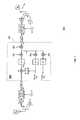
- FIG. 3illustrates baseband datapath processing in a Network Unit (DL).
- DLNetwork Unit
- FIG. 4illustrates baseband datapath processing in a User Unit (DL).
- DLUser Unit
- FIG. 5illustrates a communications channel in the UNII band in accordance with another aspect.
- FIG. 6illustrates other baseband datapath processing in a Network Unit (DL).
- DLNetwork Unit
- FIG. 7illustrates other baseband datapath processing in a User Unit (DL).
- DLUser Unit
- This documentdescribes wireless communications techniques and links that provide additional multipath fading protection by providing extra frequency and path diversity.
- the systems and methods disclosed hereare based on a link using multi-carrier Spread Spectrum modulation for a middle link in a three-hop repeater, to combat the multipath frequency selective fading of an indoor channel.
- An example of a device using such a linkis the three-hop cellular booster (referred to hereafter as “3-hop repeater”) discussed in patent applications WO2005025078 by Mohebbi, filed Sep. 3, 2003 and WO2005069249 by Mohebbi filed Jan. 12, 2004.
- the linkis not limited to any, specific 3-hop repeater, and can be used between any two (or more) devices operating in the licensed or unlicensed bands (e.g. UNII band).
- the downlink received signal (S 1 )is the waveform in a 5 MHz Wideband Code Division Multiple Access (WCDMA) operating frequency.
- the waveformis a CDMA signal transmitted from the NB to mobiles with a chipping rate of 3.84 Mchips/s passed through a SRRC pulse shaping filter with a roll-off of 0.22, fitting into a 5 MHz spectrum, defining a single signaling channel in WCDMA system.
- the signal in the 5 MHz channel (S 1 )is then received by the Network unit, converted to baseband and digitized (in a digital implementation of Network unit) for further signal processing.
- the sampling frequency of the ADC/DACis assumed to be sufficiently high for the signal processing operation (e.g. 80 Msamples/s).
- FIG. 3shows an example of a baseband signal processor 302 and operations in the network unit 300 for the downlink arrangement shown in FIG. 2 .
- cellular signal received signal strength indication(RSSI) is estimated at TX power calculation block 304 .
- the RSSI informationis then used in pilot signal generator block 306 , where a pilot signal is generated at 3.84 Mchips/s, filtered with a square-root raised-cosine (SRRC) pulse shaping filter with a role-off factor of 0.22, and amplitude-adjusted such that its insertion under the cellular signal (around 15 dB lower, for example) does not cause any noticeable interference to the cellular signal.
- SRRCsquare-root raised-cosine
- the combined signalis then replicated and modulated by several different complex carriers, with 5 MHz spacing.
- the replicated signals, now centered at different carrier frequenciesare then added together and further summed with the signal from the control channel and filtered by channel filtering block 308 before Digital-to-Analogue conversion (DAC) by DAC block 312 , and up-conversion to a UNII channel and filtering by quadrature up converter and filter block 314 , for subsequent transmission to the User unit (S 2 ).
- the channel filtering filter block 308 shown in FIG. 3ensures that the transmitted signal conforms to the spectral mask emission requirements of UNII band, and depending on the final spectrum shape of the signal, it may or may not be required. If used, care has to be taken not to distort the cellular signal excessively, which could lead to appreciable loss of Processing Gain (PG).
- PGProcessing Gain
- the complex carrier frequencies f ⁇ 2.5 , f ⁇ 7.5 , f +2.5 and f +7.5are 2.5, 7.5 MHz below and above the defined centre frequency (f) of a given UNII channel respectively.
- the communications channel between the Network and User units at UNII bandis adapted to also support the control channel that exists between the two devices with a data rate of approximately 1 Mbits/s, although other data rates may suitably be used.
- control channelThere are several options for supporting the control channel at the physical layer. These options include spreading control data to the full bandwidth of the UNII band signaling channel (20 MHz in FIGS. 2 and 3 ).
- the control datacan be pulsed shaped to fit to the channel, and inserted with a power below the cellular signal power, such that it does not interfere with the cellular signal (e.g. 20 dB below). This is the option shown in FIG. 3 .
- the block TX power Calculation block 304estimates the power of the received cellular signal (S 1 ), which is then used in a control channel modem block 310 to adjust the insertion power of the control channel, such that it does not degrade the cellular signal quality.
- Another option for supporting the control channel at the physical layerincludes allocating a portion (for example, 5 MHz or less) of the UNII channel to the control channel.
- a portionfor example, 5 MHz or less
- the example in FIG. 2will have three replicas of the cellular signal, along with a 5 MHz signaling allocated to the control channel, and the power of the control channel can be set to a desired value.
- Other techniquessuch as regular “blank-and-burst” or “dim-and-burst” transmissions techniques can also be used to send the control information. Selection of blanking repetition rate and the burst duration are executed such that the degradation of the cellular signal is kept to a minimum (e.g. 10 ⁇ sec OFDM burst every 1 msec).
- FIG. 4shows a downlink baseband processor 402 for the User unit 400 and downlink datapath which is used to receive signals (S 3 ) transmitted by the Network Unit shown in FIG. 3 (S 2 ).
- the carrier frequency offsetis removed from each of the replicated carriers in baseband, before a combiner block 404 performs combining (Selection or maximal ratio combining (MRC)) on the received 5 MHz signaling channels.
- Selection combiningcan be based on the received signal RSSI of each channel
- MRCrequires channel estimation for each 5 MHz signaling channel by a channel estimator 406 .
- CPICHcan be used (if downlink) or the dedicated inserted pilot underlays (as discussed above) can be used.
- each individual channelis associated with and uses its own channel estimator 406 .
- a Control Channel Modem block 414is the receiver unit for the control channel signal and is similar to a RAKE finger, with despreader, AFC, DLL and other modem functions for receiving, demodulating and detecting the information bits on the control channel.
- the downlink received signal (S 1 in FIG. 2 )is replicated and transmitted by the Network unit in UNII channel (S 2 in FIG. 2 ), it is alternatively possible to spread the received signal (S 1 in FIG. 5 ) to the entire signaling bandwidth of the UNII channel (S 2 in FIG. 5 ), which is 20 MHz in the example, as shown in FIG. 5 .
- the modulation scheme shown in FIG. 2will provide frequency diversity, it may not provide the path diversity possible by higher chipping rate provided by the scheme shown in FIG. 5 .
- the downlink received signalis the waveform in a 5 MHz WCDMA operating frequency.
- the waveformis a CDMA signal transmitted from the NB to mobiles with a chipping rate of 3.84 Mchips/s passed through a SRRC pulse shaping filter with a roll-off factor of 0.22, fitting into a 5 MHz spectrum, defining a single signaling channel in WCDMA system.
- the signal in the 5 MHz channel (S 1 )is then received by the Network unit, converted to baseband and digitized (in a digital implementation of Network unit) for further signal processing.
- the sampling frequency of the ADC/DACis assumed to be sufficiently high for the signal processing operation (e.g. 80 Msamples/s).
- FIG. 6shows an example of downlink baseband signal processor 602 and operations in the Network unit 600 for the arrangement shown in FIG. 5 .
- the received cellular signalis spread further by a channelization code (Ch 1 ) with a chipping rate of 11 MChips/s (the 11 MChips/s chipping rate is an example and can be different or optimized further).
- the pilot channel datais spread by a channelization code (Ch 2 ) with the same chipping rate of 11 MChips/s.
- Control channel datais spread by a channelization code (Ch 3 ) which also has a chipping rate of say 11 MChips/s. All three channelization codes Ch 1 , Ch 2 and Ch 3 are orthogonal to each other.
- the pilot and control channelsare weighted for a set magnitude before they are quadrature modulated and added to the channelized data path.
- the magnitudes of the pilot and the control channelsare calculated by TX power calculator block 605 and adjusted such that they have negligible interference on the cellular signal.
- the summed signalis then spread by the complex scrambling code (Sc) with the same chipping rate as the channelization codes (11 MChips/s in this example) and is filtered by an SRRC pulse shaping filter with a roll-off factor of 0.22 by channel filtering block 606 . This gives a resulting signal with a ⁇ 3 dB bandwidth of around 18 MHz, which should fit into the 20 MHz channel bandwidth of the UNII band.
- Sccomplex scrambling code
- control channeli.e. of 1 Mbits/s
- physical layerOther options for supporting the control channel, i.e. of 1 Mbits/s, at the physical layer include spreading control data to the full bandwidth of the UNII band signaling channel (20 MHz in FIGS. 2 and 3 ), pulsed shaped to fit to the channel, and is inserted with a power below the cellular signal power, such that it does not interfere with the cellular signal (e.g. 20 dB below).
- the optionsalso include allocating a portion (5 MHz or less) of the UNII channel to the control channel, using any desired modulation. For example, with this option, the example in FIG. 5 will have about 13 MHz of bandwidth for cellular signal, along with a 5 MHz signaling allocated to the control channel. With this option, the power of control channel can be set to a desired value. Other techniques, such as regular “blank-and-burst” or “Dim-and-burst”transmissions, can also be used to send the control information. Selection of blanking repetition rate and the burst duration must be executed such that the degradation of the cellular signal is kept to a minimum (e.g. 10 ⁇ sec OFDM burst every 1 msec).
- FIG. 7shows a downlink baseband datapath processor 702 of the User unit 700 which is used to receive signals (S 3 ) transmitted by the Network Unit shown in FIG. 6 (S 2 ).
- An optional SRRC filter with roll-off factor 0.22can be used as the first block in the baseband datapath processing (not shown in FIG. 7 ).
- spread spectrum modulationis removed by despreading the scrambling and channelization codes and low-pass filtering each data, pilot and control channels to the original signal bandwidth.
- the data path low-pass filter (LPF 1 )has a similar (or slightly higher) bandwidth to original cellular signal BW before the spreading in the Network unit.
- Low-pass filter for the pilot channelcan have any bandwidth between the transmitted signal BW (18 MHz in this example) down to 1 Hz. The smaller the BW, the higher will be the processing gain of the Pilot channel and the longer the response time of this channel. A preferred choice for the LPF 2 bandwidth is the bandwidth of LPF 1 .
- the low-pass filter for the Control channelis set to the control channel data rate or, alternatively, an integrator-and-dump, sampling at the control channel symbol rate can be used.
- the signalis phase corrected by the channel estimate at multiplier (CP) and is returned to analogue domain by the DAC, up converted and filtered for transmission on the original downlink frequency band of the cellular network (S 4 ).
- S 1 and S 4are substantially at the same carrier frequency.
- FIG. 7 operationsare similar to a RAKE finger for all three datapath, pilot and control channels, with despreader, AFC, DLL and other modem functions for receiving, demodulating and detecting the information bits on the control channel.
- a number of Rake fingersto optimally utilize the path diversity gain of time dispersive channels.
- both receiver structures shown in FIGS. 4 and 7to use the well know Equalization algorithms such as MMSE to reduce the ISI (or ICI) introduced in the UNII channel.
- antenna diversity combiningsuch as MRC, before or after the despreading operation. If used before, the technique described in U.S. Provisional Patent Application No. 60/932,677 filed on Jun.
Landscapes
- Engineering & Computer Science (AREA)
- Computer Networks & Wireless Communication (AREA)
- Signal Processing (AREA)
- Mobile Radio Communication Systems (AREA)
Abstract
Description
Claims (14)
Priority Applications (1)
| Application Number | Priority Date | Filing Date | Title |
|---|---|---|---|
| US12/251,420US8351366B2 (en) | 2007-10-11 | 2008-10-14 | CDMA UNII link |
Applications Claiming Priority (2)
| Application Number | Priority Date | Filing Date | Title |
|---|---|---|---|
| US97935207P | 2007-10-11 | 2007-10-11 | |
| US12/251,420US8351366B2 (en) | 2007-10-11 | 2008-10-14 | CDMA UNII link |
Publications (2)
| Publication Number | Publication Date |
|---|---|
| US20090129442A1 US20090129442A1 (en) | 2009-05-21 |
| US8351366B2true US8351366B2 (en) | 2013-01-08 |
Family
ID=40352145
Family Applications (1)
| Application Number | Title | Priority Date | Filing Date |
|---|---|---|---|
| US12/251,420Active2030-06-27US8351366B2 (en) | 2007-10-11 | 2008-10-14 | CDMA UNII link |
Country Status (8)
| Country | Link |
|---|---|
| US (1) | US8351366B2 (en) |
| EP (1) | EP2203989B1 (en) |
| KR (1) | KR20100091172A (en) |
| CN (1) | CN101843011A (en) |
| AU (1) | AU2008310560A1 (en) |
| CA (1) | CA2702267A1 (en) |
| ES (1) | ES2604209T3 (en) |
| WO (1) | WO2009049326A1 (en) |
Cited By (1)
| Publication number | Priority date | Publication date | Assignee | Title |
|---|---|---|---|---|
| US20130337861A1 (en)* | 2012-06-18 | 2013-12-19 | Qualcomm Incorporated | Apparatus and methods for efficient power control for tune away mode in a dsds device |
Families Citing this family (5)
| Publication number | Priority date | Publication date | Assignee | Title |
|---|---|---|---|---|
| US9083434B2 (en)* | 2011-09-21 | 2015-07-14 | Telefonaktiebolaget L M Ericsson (Publ) | System and method for operating a repeater |
| US8086174B2 (en)* | 2009-04-10 | 2011-12-27 | Nextivity, Inc. | Short-range cellular booster |
| US9379990B2 (en)* | 2013-05-27 | 2016-06-28 | Vantrix Corporation | System and method for streaming a media file from a server to a client device |
| EP3289730B1 (en) | 2015-04-27 | 2021-09-29 | CommScope Technologies LLC | Transport of modulated radio communication signals over data networks |
| US10855363B2 (en)* | 2018-05-07 | 2020-12-01 | Wilson Electronics, Llc | Multiple-input multiple-output (MIMO) repeater system |
Citations (15)
| Publication number | Priority date | Publication date | Assignee | Title |
|---|---|---|---|---|
| US5857144A (en)* | 1996-08-09 | 1999-01-05 | Ericsson, Inc. | In-band vehicular repeater for trunked radio system |
| US20020021749A1 (en)* | 2000-07-10 | 2002-02-21 | Yong-Hwan Lee | Method and apparatus for direct sequence spread spectrum receiver using an adaptive channel estimator |
| US20020075830A1 (en)* | 2000-10-16 | 2002-06-20 | Hartman David L. | Adaptive modulation for fixed wireless link in cable transmission system |
| US20020176485A1 (en)* | 2001-04-03 | 2002-11-28 | Hudson John E. | Multi-cast communication system and method of estimating channel impulse responses therein |
| US20030048834A1 (en)* | 1998-08-10 | 2003-03-13 | Kamilo Feher | Spectrally efficient FQPSK, FGMSK, and FQAM for enhanced performance CDMA, TDMA, GSM, OFDM, and other systems |
| US20030124976A1 (en)* | 2001-12-28 | 2003-07-03 | Tsuyoshi Tamaki | Multi point wireless transmission repeater system and wireless equipments |
| US20030186718A1 (en)* | 2000-08-17 | 2003-10-02 | Bernhard Raaf | Method for regulating the transmission power in a radio communication system |
| US20030236067A1 (en)* | 2002-06-20 | 2003-12-25 | Abraham Hasarchi | Repeater with digital channelizer |
| US6697642B1 (en)* | 2000-07-19 | 2004-02-24 | Texas Instruments Incorporated | Wireless communications apparatus |
| US20040202138A1 (en) | 2001-01-16 | 2004-10-14 | Song Iick Ho | Multicarrier DS/CDMA system using a turbo code with nonuniform repetition coding |
| US20040246936A1 (en)* | 2003-02-14 | 2004-12-09 | Rearden Studios, Inc. | Self-configuring, adaptive, three-dimensional, wireless network |
| US20050059342A1 (en)* | 2002-01-07 | 2005-03-17 | Marc Engels | Wireless cellular network architecture |
| WO2007037635A2 (en) | 2005-09-28 | 2007-04-05 | Lg Electronics Inc. | A method of cooperatively relaying data in cellular networks for a broadcast multicast services |
| US20080130723A1 (en)* | 2006-12-04 | 2008-06-05 | Electronics And Telecommunications Research Institute | Method for ranging with access point and repeater in wireless communication system |
| US20090042594A1 (en)* | 2007-08-10 | 2009-02-12 | Qualcomm Incorporated | Adaptation of transmit power based on maximum received signal strength |
Family Cites Families (4)
| Publication number | Priority date | Publication date | Assignee | Title |
|---|---|---|---|---|
| AU2004303118A1 (en) | 2003-09-03 | 2005-03-17 | Behzad Mohebbi | Short-range cellular booster |
| ES2551028T3 (en) | 2004-01-12 | 2015-11-13 | Nextivity, Inc. | Short range cell amplifier |
| US8452231B2 (en)* | 2006-02-03 | 2013-05-28 | Nextivity, Inc. | Short range booster |
| CN100555907C (en)* | 2007-02-05 | 2009-10-28 | 北京邮电大学 | A kind of wireless multi-hop relay networking method that supports multi-media broadcasting service |
- 2008
- 2008-10-14EPEP08838370.8Apatent/EP2203989B1/ennot_activeNot-in-force
- 2008-10-14CACA2702267Apatent/CA2702267A1/ennot_activeAbandoned
- 2008-10-14CNCN200880111255Apatent/CN101843011A/enactivePending
- 2008-10-14USUS12/251,420patent/US8351366B2/enactiveActive
- 2008-10-14KRKR1020107009787Apatent/KR20100091172A/ennot_activeWithdrawn
- 2008-10-14WOPCT/US2008/079894patent/WO2009049326A1/enactiveApplication Filing
- 2008-10-14ESES08838370.8Tpatent/ES2604209T3/enactiveActive
- 2008-10-14AUAU2008310560Apatent/AU2008310560A1/ennot_activeAbandoned
Patent Citations (15)
| Publication number | Priority date | Publication date | Assignee | Title |
|---|---|---|---|---|
| US5857144A (en)* | 1996-08-09 | 1999-01-05 | Ericsson, Inc. | In-band vehicular repeater for trunked radio system |
| US20030048834A1 (en)* | 1998-08-10 | 2003-03-13 | Kamilo Feher | Spectrally efficient FQPSK, FGMSK, and FQAM for enhanced performance CDMA, TDMA, GSM, OFDM, and other systems |
| US20020021749A1 (en)* | 2000-07-10 | 2002-02-21 | Yong-Hwan Lee | Method and apparatus for direct sequence spread spectrum receiver using an adaptive channel estimator |
| US6697642B1 (en)* | 2000-07-19 | 2004-02-24 | Texas Instruments Incorporated | Wireless communications apparatus |
| US20030186718A1 (en)* | 2000-08-17 | 2003-10-02 | Bernhard Raaf | Method for regulating the transmission power in a radio communication system |
| US20020075830A1 (en)* | 2000-10-16 | 2002-06-20 | Hartman David L. | Adaptive modulation for fixed wireless link in cable transmission system |
| US20040202138A1 (en) | 2001-01-16 | 2004-10-14 | Song Iick Ho | Multicarrier DS/CDMA system using a turbo code with nonuniform repetition coding |
| US20020176485A1 (en)* | 2001-04-03 | 2002-11-28 | Hudson John E. | Multi-cast communication system and method of estimating channel impulse responses therein |
| US20030124976A1 (en)* | 2001-12-28 | 2003-07-03 | Tsuyoshi Tamaki | Multi point wireless transmission repeater system and wireless equipments |
| US20050059342A1 (en)* | 2002-01-07 | 2005-03-17 | Marc Engels | Wireless cellular network architecture |
| US20030236067A1 (en)* | 2002-06-20 | 2003-12-25 | Abraham Hasarchi | Repeater with digital channelizer |
| US20040246936A1 (en)* | 2003-02-14 | 2004-12-09 | Rearden Studios, Inc. | Self-configuring, adaptive, three-dimensional, wireless network |
| WO2007037635A2 (en) | 2005-09-28 | 2007-04-05 | Lg Electronics Inc. | A method of cooperatively relaying data in cellular networks for a broadcast multicast services |
| US20080130723A1 (en)* | 2006-12-04 | 2008-06-05 | Electronics And Telecommunications Research Institute | Method for ranging with access point and repeater in wireless communication system |
| US20090042594A1 (en)* | 2007-08-10 | 2009-02-12 | Qualcomm Incorporated | Adaptation of transmit power based on maximum received signal strength |
Cited By (2)
| Publication number | Priority date | Publication date | Assignee | Title |
|---|---|---|---|---|
| US20130337861A1 (en)* | 2012-06-18 | 2013-12-19 | Qualcomm Incorporated | Apparatus and methods for efficient power control for tune away mode in a dsds device |
| US9094918B2 (en)* | 2012-06-18 | 2015-07-28 | Qualcomm Incorporated | Apparatus and methods for efficient power control for tune away mode in a DSDS device |
Also Published As
| Publication number | Publication date |
|---|---|
| CA2702267A1 (en) | 2009-04-16 |
| ES2604209T3 (en) | 2017-03-03 |
| CN101843011A (en) | 2010-09-22 |
| WO2009049326A1 (en) | 2009-04-16 |
| US20090129442A1 (en) | 2009-05-21 |
| EP2203989A1 (en) | 2010-07-07 |
| KR20100091172A (en) | 2010-08-18 |
| EP2203989B1 (en) | 2016-10-05 |
| AU2008310560A1 (en) | 2009-04-16 |
Similar Documents
| Publication | Publication Date | Title |
|---|---|---|
| US8009748B2 (en) | Downlink channel transmission device and method thereof | |
| KR100818774B1 (en) | Method and apparatus for overlaying multi-carrier and direct sequence spread spectrum signals in a broadband wireless communication system | |
| US7545846B2 (en) | Interference cancellation in a spread spectrum communication system | |
| US7324434B2 (en) | Radio transmission system and method, and transmitter apparatus and receiver apparatus used in the radio transmission system | |
| US20090201902A1 (en) | Uplink channel receiving and transmitting apparatuses and methods | |
| US8611205B2 (en) | Multi-hop booster | |
| EP3208985A1 (en) | Methods and apparatus for overlaying multi-carrier and direct sequence spread spectrum signals in a broadband wireless communication system | |
| AU2008245627B2 (en) | Multi-hop booster | |
| US8351366B2 (en) | CDMA UNII link | |
| EP1168652A2 (en) | Base station and mobile communication system | |
| US7885350B1 (en) | System and method for non-interfering signaling and reception of overlapping single carrier transmissions over delay spread channels | |
| Raulefs et al. | 4MORE: An advanced MIMO downlink MC-CDMA system | |
| Dahlman et al. | High data rates in mobile communications |
Legal Events
| Date | Code | Title | Description |
|---|---|---|---|
| AS | Assignment | Owner name:NEXTIVITY, INC., CALIFORNIA Free format text:ASSIGNMENT OF ASSIGNORS INTEREST;ASSIGNORS:MOHEBBI, BEHZAD B.;BOTHA, LOUIS;REEL/FRAME:022490/0832 Effective date:20081103 | |
| STCF | Information on status: patent grant | Free format text:PATENTED CASE | |
| AS | Assignment | Owner name:VENTURE LENDING & LEASING V, INC., CALIFORNIA Free format text:SECURITY INTEREST;ASSIGNOR:NEXTIVITY, INC.;REEL/FRAME:034646/0230 Effective date:20141215 Owner name:VENTURE LENDING & LEASING IV, INC., CALIFORNIA Free format text:SECURITY INTEREST;ASSIGNOR:NEXTIVITY, INC.;REEL/FRAME:034646/0230 Effective date:20141215 | |
| FPAY | Fee payment | Year of fee payment:4 | |
| AS | Assignment | Owner name:VENTURE LENDING & LEASING VII, INC., CALIFORNIA Free format text:SECURITY INTEREST;ASSIGNOR:NEXTIVITY, INC.;REEL/FRAME:041306/0273 Effective date:20161220 Owner name:VENTURE LENDING & LEASING VIII, INC., CALIFORNIA Free format text:SECURITY INTEREST;ASSIGNOR:NEXTIVITY, INC.;REEL/FRAME:041306/0273 Effective date:20161220 | |
| MAFP | Maintenance fee payment | Free format text:PAYMENT OF MAINTENANCE FEE, 8TH YR, SMALL ENTITY (ORIGINAL EVENT CODE: M2552); ENTITY STATUS OF PATENT OWNER: SMALL ENTITY Year of fee payment:8 | |
| AS | Assignment | Owner name:LIVE OAK BANKING COMPANY, NORTH CAROLINA Free format text:SECURITY INTEREST;ASSIGNOR:NEXTIVITY, INC.;REEL/FRAME:054711/0816 Effective date:20201211 | |
| AS | Assignment | Owner name:NEXTIVITY, INC., CALIFORNIA Free format text:RELEASE BY SECURED PARTY;ASSIGNORS:VENTURE LENDING & LEASING VII, INC.;VENTURE LENDING & LEASING VIII, INC.;REEL/FRAME:054863/0645 Effective date:20201211 | |
| AS | Assignment | Owner name:NEXTIVITY, INC., CALIFORNIA Free format text:RELEASE BY SECURED PARTY;ASSIGNORS:VENTURE LENDING & LEASING IV, INC.;VENTURE LENDING & LEASING V, INC.;REEL/FRAME:062180/0367 Effective date:20221215 | |
| AS | Assignment | Owner name:JPMORGAN CHASE BANK, N.A., NEW YORK Free format text:SECURITY INTEREST;ASSIGNOR:NEXTIVITY, INC.;REEL/FRAME:062213/0590 Effective date:20221222 | |
| AS | Assignment | Owner name:NEXTIVITY, INC., CALIFORNIA Free format text:RELEASE BY SECURED PARTY;ASSIGNORS:VENTURE LENDING & LEASING IV, INC;VENTURE LENDING & LEASING V, INC.;REEL/FRAME:062222/0344 Effective date:20221227 | |
| AS | Assignment | Owner name:WTI FUND X, INC., CALIFORNIA Free format text:SECURITY INTEREST;ASSIGNOR:NEXTIVITY, INC.;REEL/FRAME:067666/0001 Effective date:20240529 |