US8351197B2 - Holding device for hard disk drive - Google Patents
Holding device for hard disk driveDownload PDFInfo
- Publication number
- US8351197B2 US8351197B2US13/097,088US201113097088AUS8351197B2US 8351197 B2US8351197 B2US 8351197B2US 201113097088 AUS201113097088 AUS 201113097088AUS 8351197 B2US8351197 B2US 8351197B2
- Authority
- US
- United States
- Prior art keywords
- sidewall
- pair
- holding device
- clamping
- clamping portions
- Prior art date
- Legal status (The legal status is an assumption and is not a legal conclusion. Google has not performed a legal analysis and makes no representation as to the accuracy of the status listed.)
- Expired - Fee Related, expires
Links
Images


Classifications
- G—PHYSICS
- G11—INFORMATION STORAGE
- G11B—INFORMATION STORAGE BASED ON RELATIVE MOVEMENT BETWEEN RECORD CARRIER AND TRANSDUCER
- G11B33/00—Constructional parts, details or accessories not provided for in the other groups of this subclass
- G11B33/12—Disposition of constructional parts in the apparatus, e.g. of power supply, of modules
- G11B33/121—Disposition of constructional parts in the apparatus, e.g. of power supply, of modules the apparatus comprising a single recording/reproducing device
- G11B33/123—Mounting arrangements of constructional parts onto a chassis
- G11B33/124—Mounting arrangements of constructional parts onto a chassis of the single recording/reproducing device, e.g. disk drive, onto a chassis
- G—PHYSICS
- G11—INFORMATION STORAGE
- G11B—INFORMATION STORAGE BASED ON RELATIVE MOVEMENT BETWEEN RECORD CARRIER AND TRANSDUCER
- G11B33/00—Constructional parts, details or accessories not provided for in the other groups of this subclass
- G11B33/02—Cabinets; Cases; Stands; Disposition of apparatus therein or thereon
- G11B33/08—Insulation or absorption of undesired vibrations or sounds
Definitions
- the disclosuregenerally relates to holding devices and, particularly, to a holding device for holding hard disk drives (HDDs).
- HDDshard disk drives
- HDDsare usually fastened to a holding device by screws.
- elastic tubesare sleeved on the screws to act shock absorbers.
- the employment of the elastic tubescomplicates the assembly process of the HDD and the holding device, decreasing efficiency of the process.
- FIG. 1is an isometric, exploded view of a holding device for holding an HDD in accordance with an exemplary embodiment.
- FIG. 2is an assembled view of the holding device and the HDD of FIG. 1 .
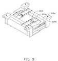
- FIG. 3is similar to FIG. 2 , but viewed from another angle.
- the holding device 100is configured for holding a hard disk drive (HDD) 300 .
- the HDD 300is generally rectangular and includes a first end 301 and a second end 302 opposite to the first end 301 .
- the holding device 100includes two elastic members 10 and two frame members 20 .
- the two elastic members 10are made of elastic material such as rubber.
- Each elastic member 10includes a generally rectangular plate portion 101 , a pair of first walls 102 extending up from two respective long sides of the plate portion 101 , and a pair of second walls 103 extending up from two respective short sides of the plate portion 101 .
- the plate portion 101 , the first walls 102 , and the second walls 103cooperatively define a receiving space 104 .
- the receiving space 104is configured for receiving a corresponding end of the HDD 300 .
- each elastic member 10may include only the plate portion 101 and the pair of first walls 102 to form the receiving space 104 or each elastic member 10 may include only the pair of first walls 102 and the second walls 103 to form the receiving space 104 .
- the two frame members 20are made of plastic by, e.g., injection molding. Each frame member 20 is integratedly formed and includes a generally rectangular base portion 201 , a first sidewall 202 a , a second sidewall 202 b , two pairs of clamping portions 203 , a pair of limiting walls 204 , and a pair of connection portions 205 .
- the base portion 201includes a first surface 201 a and a second surface 201 b opposite to the first surface 201 a .
- the first sidewall 202 a and the second sidewall 202 bperpendicularly extend from two respective long sides of the first surface 201 a .
- the first sidewall 202 a , the second sidewall 202 b , and the first surface 201 acooperatively define a groove 202 c .
- the groove 202 cis configured to receive a corresponding elastic member 10 .
- Each pair of clamping portions 203includes a clamping arm 203 a and an engaging arm 203 b .
- the two clamping arms 203 arespectively extend from the first sidewall 202 a and the second sidewall 202 b .
- the two engaging arms 203 balso extend from the first sidewall 202 a and the second sidewall 202 b .
- the clamping arm 203 a and the engaging arm 203 b in the same pair of clamping portions 203are aligned with each other.
- the clamping arm 203 ais generally an elongated plate and includes a hook 2031 protruding from a surface opposite to the corresponding engaging arm 203 b at an end of the clamping arm 203 a away from the first sidewall 202 a or the second sidewall 202 b .
- the engaging arm 203 b opposite to the corresponding clamping arm 203 ais generally an elongated plate and defines a through hole 2032 opposite to the corresponding hook 2031 .
- a pair of ribs 2033extends up from two long sides of the engaging arm 203 b opposite to the corresponding clamping arm 203 a .
- the ribs 2033are configured to reinforce the engaging arm 203 b.
- the pair of limiting walls 204extends up from two short sides of the first surface 201 a .
- Each limiting wall 204is connected between the first sidewall 202 a and the second sidewall 202 b.
- connection portion 205extends out from the second surface 201 b .
- Each connection portion 205is plated-shape and includes a top surface 205 a , a bottom surface 205 b opposite to the top surface 205 a , and a cylinder aligning portion 205 d perpendicularly extending from the bottom surface 205 b .
- the connection portion 205also defines a mounting hole 205 c extending from the top surface 205 a to the bottom surface 205 b .
- the mounting hole 205 cis configured to be mounted to an external mounting plate (not shown).
- the aligning portion 205 dis configured to align with an aligning hole of the external mounting plate.
- the bottom surface 205 bis parallel to the second sidewall 202 b and protrudes out of the second sidewall 202 b.
- the first end 301 and the second end 302are respectively received in the receiving spaces 104 of the two elastic members 10 .
- the two elastic members 10are respectively received in the grooves 202 c of the two frame members 20 .
- the hooks 2031 of one of the frame members 20are engaged with the through holes 2032 of the other frame member 20 .
- the two frame members 20are clamped to each other by the clamping portions 203 .
- the first end 301 and the second end 302are encased by the two elastic members 10 , thus, the HDD 300 is well protected from shock.
- the two frame members 20can be efficiently assembled using the corresponding clamping portions 203 .
- the clamping portions 203 of the two frame members 20are configured to clamp together.
- the frame member 20may include only a pair of clamping portions 203 or more than two pairs of clamping portions 203 .
- the limiting walls 204are configured to prevent the elastic member 10 being pushed out of the groove 203 c.
Landscapes
- Vibration Prevention Devices (AREA)
- Buckles (AREA)
- Casings For Electric Apparatus (AREA)
Abstract
Description
1. Technical Field
The disclosure generally relates to holding devices and, particularly, to a holding device for holding hard disk drives (HDDs).
2. Description of Related Art
HDDs are usually fastened to a holding device by screws. To protect the HDD from being damaged by shocks and heavy vibrations, elastic tubes are sleeved on the screws to act shock absorbers. However, the employment of the elastic tubes complicates the assembly process of the HDD and the holding device, decreasing efficiency of the process.
Therefore, what needed is a holding device, which can overcome the above shortcomings.
Many aspects of the disclosure can be better understood with reference to the following drawings. The components in the drawings are not necessarily drawn to scale, the emphasis instead being placed upon clearly illustrating the principles of the disclosure. Moreover, in the drawings, like reference numerals designate corresponding parts throughout the several views.
Embodiments of the present disclosure will now be described in detail below and with reference to the drawings.
Referring toFIG. 1 toFIG. 3 , aholding device 100 in accordance with an exemplary embodiment is shown. Theholding device 100 is configured for holding a hard disk drive (HDD)300. The HDD300 is generally rectangular and includes afirst end 301 and asecond end 302 opposite to thefirst end 301.
Theholding device 100 includes twoelastic members 10 and twoframe members 20.
The twoelastic members 10 are made of elastic material such as rubber. Eachelastic member 10 includes a generallyrectangular plate portion 101, a pair offirst walls 102 extending up from two respective long sides of theplate portion 101, and a pair ofsecond walls 103 extending up from two respective short sides of theplate portion 101. Theplate portion 101, thefirst walls 102, and thesecond walls 103 cooperatively define areceiving space 104. Thereceiving space 104 is configured for receiving a corresponding end of theHDD 300. In alternative embodiments, eachelastic member 10 may include only theplate portion 101 and the pair offirst walls 102 to form thereceiving space 104 or eachelastic member 10 may include only the pair offirst walls 102 and thesecond walls 103 to form thereceiving space 104.
The twoframe members 20 are made of plastic by, e.g., injection molding. Eachframe member 20 is integratedly formed and includes a generallyrectangular base portion 201, afirst sidewall 202a, asecond sidewall 202b, two pairs ofclamping portions 203, a pair of limitingwalls 204, and a pair ofconnection portions 205. Thebase portion 201 includes a first surface201aand asecond surface 201bopposite to the first surface201a. Thefirst sidewall 202aand thesecond sidewall 202bperpendicularly extend from two respective long sides of the first surface201a. Thefirst sidewall 202a, thesecond sidewall 202b, and the first surface201acooperatively define a groove202c. The groove202cis configured to receive a correspondingelastic member 10.
Each pair ofclamping portions 203 includes aclamping arm 203aand anengaging arm 203b. The two clampingarms 203arespectively extend from thefirst sidewall 202aand thesecond sidewall 202b. The twoengaging arms 203balso extend from thefirst sidewall 202aand thesecond sidewall 202b. Theclamping arm 203aand theengaging arm 203bin the same pair of clampingportions 203 are aligned with each other.
Theclamping arm 203ais generally an elongated plate and includes ahook 2031 protruding from a surface opposite to the correspondingengaging arm 203bat an end of theclamping arm 203aaway from thefirst sidewall 202aor thesecond sidewall 202b. Theengaging arm 203bopposite to thecorresponding clamping arm 203ais generally an elongated plate and defines a throughhole 2032 opposite to thecorresponding hook 2031. A pair ofribs 2033 extends up from two long sides of theengaging arm 203bopposite to thecorresponding clamping arm 203a. Theribs 2033 are configured to reinforce theengaging arm 203b.
The pair oflimiting walls 204 extends up from two short sides of the first surface201a. Eachlimiting wall 204 is connected between thefirst sidewall 202aand thesecond sidewall 202b.
The pair ofconnection portions 205 extends out from thesecond surface 201b. Eachconnection portion 205 is plated-shape and includes atop surface 205a, abottom surface 205bopposite to thetop surface 205a, and acylinder aligning portion 205dperpendicularly extending from thebottom surface 205b. Theconnection portion 205 also defines amounting hole 205cextending from thetop surface 205ato thebottom surface 205b. Themounting hole 205cis configured to be mounted to an external mounting plate (not shown). The aligningportion 205dis configured to align with an aligning hole of the external mounting plate. Thebottom surface 205bis parallel to thesecond sidewall 202band protrudes out of thesecond sidewall 202b.
When assembling theHDD 300 to theholding device 100, thefirst end 301 and thesecond end 302 are respectively received in thereceiving spaces 104 of the twoelastic members 10. Then the twoelastic members 10 are respectively received in the grooves202cof the twoframe members 20. Thehooks 2031 of one of theframe members 20 are engaged with the throughholes 2032 of theother frame member 20. Thus, the twoframe members 20 are clamped to each other by theclamping portions 203.
Thefirst end 301 and thesecond end 302 are encased by the twoelastic members 10, thus, theHDD 300 is well protected from shock. The twoframe members 20 can be efficiently assembled using thecorresponding clamping portions 203. The clampingportions 203 of the twoframe members 20 are configured to clamp together. In alternative embodiments, theframe member 20 may include only a pair of clampingportions 203 or more than two pairs of clampingportions 203. Thelimiting walls 204 are configured to prevent theelastic member 10 being pushed out of the groove203c.
It is understood that the above-described embodiment is intended to illustrate rather than limit the disclosure. Variations may be made to the embodiment without departing from the spirit of the disclosure. Accordingly, it is appropriate that the appended claims be construed broadly and in a manner consistent with the scope of the disclosure.
Claims (10)
1. A holding device for holding a hard disk drive, the hard disk drive comprising a first end and a second end, the holding device comprising:
two elastic members, one elastic member being configured for encasing the first end, and the other elastic member being configured for encasing the second end; and
two frame members, each frame member comprising:
a base portion comprising a first surface and a second surface opposite to the first surface;
a first sidewall;
a second sidewall, the first and second sidewalls extending from two opposite ends of the base portion, the first sidewall, the second sidewall, and the first surface cooperatively defining a groove, the groove receiving a corresponding one of the two elastic members and
two pairs of clamping portions, the clamping portions in each pair of clamping portions extending out from the first sidewall and the second sidewall and configured for engaging with a corresponding pair of clamping portions of another frame member;
wherein each pair of clamping portions comprises a clamping arm and an engaging arm, the two clamping arms of the two pairs of clamping portions extend from the first sidewall and the second sidewall respectively, the two engaging arms of the two pairs of clamping portions also extend from the first sidewall and the second sidewall, the clamping arm and the engaging arm in each pair of clamping portions are aligned with each other, each engaging arm comprises a pair of ribs, the ribs extend up from two long sides of the engaging arm.
2. The holding device ofclaim 1 , wherein each clamping arm is an elongated plate and comprises a hook, the hook protrudes from a surface of the clamping arm, each engaging arm is an elongated plate and defines a through hole configured for receiving the hook of a corresponding clamping arm of another frame member.
3. The holding device ofclaim 1 , wherein each frame member comprises a pair of limiting walls opposite to each other and extending outwardly form the first surface, each limiting wall connects between the first sidewall and the second sidewall.
4. The holding device ofclaim 1 , wherein each elastic members comprises a rectangular plate portion, a pair of first walls perpendicularly connecting to two opposite ends of the plate portion, and a pair of second walls perpendicularly connecting to another two opposite ends of the plate portion, the plate portion, the first walls and the second walls cooperatively defines a receiving space for encasing a corresponding one of the first and second ends.
5. The holding device ofclaim 1 , wherein each elastic member comprises a rectangular plate portion, a pair of first walls perpendicularly connecting to two opposite ends of the plate portion, the plate portion and the first walls cooperatively defines a receiving space for encasing a corresponding one of the first and second ends.
6. The holding device ofclaim 1 , wherein each elastic member comprises a pair of first walls opposite to each other and a pair of second walls opposite to each other, each second wall perpendicularly connects with the first walls, the first walls and the second walls cooperatively defines a receiving space for encasing a corresponding one of the first and second ends.
7. The holding device ofclaim 1 , wherein each frame member comprises a pair of connection portions extending out from the second surface, each connection portion is plated-shape and comprises a top surface, a bottom surface opposite to the top surface, and a cylinder aligning portion perpendicularly extending from the bottom surface, each connection portion also defines a mounting hole through the top surface and the bottom surface.
8. The holding device ofclaim 1 , wherein the elastic members are made of rubber.
9. The holding device ofclaim 1 , wherein the frame members are made of plastic by injection molding.
10. A holding device for holding a hard disk drive, the hard disk drive comprising a first end and a second end, the holding device comprising:
two elastic members, each elastic member defining a receiving space for receiving a corresponding one of the first end and the second end; and
two frame members, each frame member defining a groove configured for receiving one of the elastic members, each frame member comprising two pairs of clamping portions, the clamping portions of one frame member being configured for engaging with the clamping portions of another frame member to hold the hard disk drive therebetween;
wherein each pair of clamping portions comprises a clamping arm and an engaging arm, the two clamping arms of the two pairs of clamping portions extend from the first sidewall and the second sidewall respectively, the two engaging arms of the two pairs of clamping portions also extend from the first sidewall and the second sidewall, the clamping arm and the engaging arm in each pair of clamping portions are aligned with each other, each engaging arm comprises a pair of ribs, the ribs extend up from two long sides of the engaging arm.
Applications Claiming Priority (3)
| Application Number | Priority Date | Filing Date | Title |
|---|---|---|---|
| CN201120041372U | 2011-02-18 | ||
| CN2011200413720UCN201994064U (en) | 2011-02-18 | 2011-02-18 | Hard disc fixing device |
| CN201120041372.0 | 2011-02-18 |
Publications (2)
| Publication Number | Publication Date |
|---|---|
| US20120212898A1 US20120212898A1 (en) | 2012-08-23 |
| US8351197B2true US8351197B2 (en) | 2013-01-08 |
Family
ID=44670545
Family Applications (1)
| Application Number | Title | Priority Date | Filing Date |
|---|---|---|---|
| US13/097,088Expired - Fee RelatedUS8351197B2 (en) | 2011-02-18 | 2011-04-29 | Holding device for hard disk drive |
Country Status (3)
| Country | Link |
|---|---|
| US (1) | US8351197B2 (en) |
| CN (1) | CN201994064U (en) |
| TW (1) | TWM419196U (en) |
Cited By (2)
| Publication number | Priority date | Publication date | Assignee | Title |
|---|---|---|---|---|
| US20170308132A1 (en)* | 2016-04-20 | 2017-10-26 | Samsung Electronics Co., Ltd. | Solid state drive (ssd) housing and ssd housing assembly |
| US10936025B2 (en)* | 2019-04-08 | 2021-03-02 | Hongfujin Precision Electronics (Tianjin) Co., Ltd. | Fixing bracket for the installion of computer expansion card |
Families Citing this family (2)
| Publication number | Priority date | Publication date | Assignee | Title |
|---|---|---|---|---|
| CN105739640B (en)* | 2014-12-09 | 2018-12-07 | 鸿富锦精密电子(天津)有限公司 | Electronic device and fixed installation of data storage unit and panel |
| CN205582485U (en)* | 2015-12-30 | 2016-09-14 | 深圳市锐明技术股份有限公司 | Hard disk cartridge, hard disk unit and electronic equipment |
Citations (45)
| Publication number | Priority date | Publication date | Assignee | Title |
|---|---|---|---|---|
| US4672510A (en)* | 1984-10-19 | 1987-06-09 | Burr-Brown Corporation | Package for an expandable remote interface unit |
| US5301088A (en)* | 1993-02-25 | 1994-04-05 | Enlight Corporation | Dovetail fastening structure for a disk drive |
| US5586002A (en)* | 1992-06-24 | 1996-12-17 | John Notarianni | Protective case and interface housing containing computer devices and the like |
| US5788211A (en)* | 1995-09-13 | 1998-08-04 | Hewlett-Packard Company | Fixing piece for data storage drive and other units |
| US6201867B1 (en)* | 1997-05-14 | 2001-03-13 | Kunihiko Koike | Portable telephone having a removable covering |
| US6219252B1 (en)* | 1998-12-31 | 2001-04-17 | Hon Hai Precision Ind. Co., Ltd. | Universal docking station |
| US6351378B1 (en)* | 2000-03-16 | 2002-02-26 | Lite-On Enclosure Inc. | Fixing device of a disk driver |
| US20020044416A1 (en)* | 2001-07-18 | 2002-04-18 | Harmon Jasper E. | Micro hard drive caddy |
| US20030011980A1 (en)* | 2001-07-13 | 2003-01-16 | International Business Machines Corporation | Shock mount for a device packaged in a portable cartridge |
| US6560102B1 (en)* | 2000-10-23 | 2003-05-06 | Belkin Components | Universal serial bus docking station |
| US6570756B2 (en)* | 2001-10-10 | 2003-05-27 | Dell Products L.P. | Personal computer system housing and security system |
| US20030174464A1 (en)* | 2002-03-14 | 2003-09-18 | Takatsugu Funawatari | Information storage device |
| US20040032711A1 (en)* | 2002-08-15 | 2004-02-19 | Kaczeus Steven L. | Data storage device |
| US20040070926A1 (en)* | 2002-06-20 | 2004-04-15 | Digital Safety Technologies, Inc. | Protective apparatus for sensitive components |
| US20040105229A1 (en)* | 2002-11-29 | 2004-06-03 | Liang-Chin Wang | Mounting apparatus for data storage device |
| US6775132B2 (en)* | 2002-09-09 | 2004-08-10 | Hon Hai Precision Ind. Co., Ltd. | Mounting apparatus for data storage device |
| US6867942B2 (en)* | 2001-04-26 | 2005-03-15 | International Business Machines Corporation | Storage device mounted in portable data storage media type cartridges |
| US20050088778A1 (en)* | 2003-10-28 | 2005-04-28 | Hon Hai Precision Industry Co., Ltd. | Mounting apparatus for data storage device |
| US20050088815A1 (en)* | 2003-10-22 | 2005-04-28 | Chen Yun L. | Hard disk mounting assembly |
| US7016190B1 (en)* | 2005-05-23 | 2006-03-21 | Inventec Corporation | Hard disk anchoring apparatus |
| US7054153B2 (en)* | 2003-10-31 | 2006-05-30 | Hewlett-Packard Development Company, L.P. | Mount for computer drive |
| US7179991B2 (en)* | 2005-01-07 | 2007-02-20 | Hon Hai Precision Industry Co., Ltd. | Case of electronic device and method for fabricating the same |
| US20070263349A1 (en)* | 2006-05-12 | 2007-11-15 | Chieh-Shih Yi | Fixing Support of Data Accessing Device |
| US20070263351A1 (en)* | 2006-05-15 | 2007-11-15 | Asustek Computer Inc. | Electronic apparatus |
| US20080013272A1 (en)* | 2006-07-14 | 2008-01-17 | Dell Products L.P. | Hard drive carrier |
| US20080037212A1 (en)* | 2006-08-08 | 2008-02-14 | Cooler Master Co., Ltd. | External box with shockproofing mechanism |
| US20080037211A1 (en)* | 2006-08-09 | 2008-02-14 | Imation Corp. | Data storage cartridge with non - tape storage medium and electrical targets |
| US20080083547A1 (en)* | 2006-10-05 | 2008-04-10 | Lear Corporation | Junction box assembly |
| US20080157638A1 (en)* | 2006-12-29 | 2008-07-03 | Universal Scientific Industrial Co., Ltd. | Hard disk drive drawer |
| US20080158808A1 (en)* | 2006-12-29 | 2008-07-03 | Toshiba America Information Systems, Inc. | Apparatus to protect shock-sensitive devices and methods of assembly |
| US7520389B2 (en)* | 2004-05-24 | 2009-04-21 | Seagate Technologies, Llc | Package structure for soft mounting direct connect storage device |
| US20090111543A1 (en)* | 2007-10-31 | 2009-04-30 | Hong Fu Jin Precision Industry (Shenzhen) Co., Ltd. | Protective sleeve for portable electronic devices |
| US20090114556A1 (en)* | 2007-11-02 | 2009-05-07 | Hong Fu Jin Precision Industry (Shenzhen) Co., Ltd. | Protective sleeve for portable electronic devices |
| US20090129009A1 (en)* | 2007-11-15 | 2009-05-21 | Hong Fu Jin Precision Industry (Shenzhen) Co., Ltd | Fixing apparatus for hard disk drive |
| US20090279244A1 (en)* | 2008-05-12 | 2009-11-12 | International Business Machines Corporation | Disk Drive Carrier and Cage Preventing Installation of Incompatible Disk Drives |
| US7701703B2 (en)* | 2007-08-30 | 2010-04-20 | Hong Fu Jin Precision Industry (Shenzhen) Co., Ltd. | Fixing apparatus for hard disk drive |
| US7782606B2 (en)* | 2008-05-12 | 2010-08-24 | International Business Machines Corporation | Hard disk drive carrier latch apparatus |
| US20110002095A1 (en)* | 2008-03-28 | 2011-01-06 | Fujitsu Limited | Electronic apparatus, assembly structure of electronic unit, and bracket |
| US20110013355A1 (en)* | 2009-07-17 | 2011-01-20 | Deng-Hsi Chen | Hard Disk Fixing Seat |
| US20110017747A1 (en)* | 2007-08-21 | 2011-01-27 | Wildman Kelvin H | Bucket-Style Fire Resistant Enclosure and a Method for Making the Same |
| US7903401B2 (en)* | 2007-12-31 | 2011-03-08 | Quanta Computer Inc. | Hard disk drive holding apparatus |
| US20110134598A1 (en)* | 2009-12-03 | 2011-06-09 | Hon Hai Precision Industry Co., Ltd. | Hard disk bracket assembly |
| US20110255235A1 (en)* | 2008-06-03 | 2011-10-20 | Deng-Hsi Chen | Disk Drive Case |
| US8218315B2 (en)* | 2009-04-25 | 2012-07-10 | Hon Hai Precision Industry Co., Ltd. | Mounting apparatus for storage device |
| US8240627B2 (en)* | 2008-11-25 | 2012-08-14 | Hong Fu Jin Precision Industry (Shenzhen) Co., Ltd. | Retaining assembly for locking disk drive |
- 2011
- 2011-02-18CNCN2011200413720Upatent/CN201994064U/ennot_activeExpired - Fee Related
- 2011-02-22TWTW100203186Upatent/TWM419196U/ennot_activeIP Right Cessation
- 2011-04-29USUS13/097,088patent/US8351197B2/ennot_activeExpired - Fee Related
Patent Citations (48)
| Publication number | Priority date | Publication date | Assignee | Title |
|---|---|---|---|---|
| US4672510A (en)* | 1984-10-19 | 1987-06-09 | Burr-Brown Corporation | Package for an expandable remote interface unit |
| US5586002A (en)* | 1992-06-24 | 1996-12-17 | John Notarianni | Protective case and interface housing containing computer devices and the like |
| US5301088A (en)* | 1993-02-25 | 1994-04-05 | Enlight Corporation | Dovetail fastening structure for a disk drive |
| US5788211A (en)* | 1995-09-13 | 1998-08-04 | Hewlett-Packard Company | Fixing piece for data storage drive and other units |
| US6201867B1 (en)* | 1997-05-14 | 2001-03-13 | Kunihiko Koike | Portable telephone having a removable covering |
| US6219252B1 (en)* | 1998-12-31 | 2001-04-17 | Hon Hai Precision Ind. Co., Ltd. | Universal docking station |
| US6351378B1 (en)* | 2000-03-16 | 2002-02-26 | Lite-On Enclosure Inc. | Fixing device of a disk driver |
| US6560102B1 (en)* | 2000-10-23 | 2003-05-06 | Belkin Components | Universal serial bus docking station |
| US6867942B2 (en)* | 2001-04-26 | 2005-03-15 | International Business Machines Corporation | Storage device mounted in portable data storage media type cartridges |
| US20030011980A1 (en)* | 2001-07-13 | 2003-01-16 | International Business Machines Corporation | Shock mount for a device packaged in a portable cartridge |
| US20020044416A1 (en)* | 2001-07-18 | 2002-04-18 | Harmon Jasper E. | Micro hard drive caddy |
| US6570756B2 (en)* | 2001-10-10 | 2003-05-27 | Dell Products L.P. | Personal computer system housing and security system |
| US20030174464A1 (en)* | 2002-03-14 | 2003-09-18 | Takatsugu Funawatari | Information storage device |
| US20040070926A1 (en)* | 2002-06-20 | 2004-04-15 | Digital Safety Technologies, Inc. | Protective apparatus for sensitive components |
| US20040032711A1 (en)* | 2002-08-15 | 2004-02-19 | Kaczeus Steven L. | Data storage device |
| US6775132B2 (en)* | 2002-09-09 | 2004-08-10 | Hon Hai Precision Ind. Co., Ltd. | Mounting apparatus for data storage device |
| US6798652B2 (en)* | 2002-11-29 | 2004-09-28 | Hon Hai Precision Ind. Co., Ltd | Mounting apparatus for data storage device |
| US20040105229A1 (en)* | 2002-11-29 | 2004-06-03 | Liang-Chin Wang | Mounting apparatus for data storage device |
| US20050088815A1 (en)* | 2003-10-22 | 2005-04-28 | Chen Yun L. | Hard disk mounting assembly |
| US20050088778A1 (en)* | 2003-10-28 | 2005-04-28 | Hon Hai Precision Industry Co., Ltd. | Mounting apparatus for data storage device |
| US7054153B2 (en)* | 2003-10-31 | 2006-05-30 | Hewlett-Packard Development Company, L.P. | Mount for computer drive |
| US7520389B2 (en)* | 2004-05-24 | 2009-04-21 | Seagate Technologies, Llc | Package structure for soft mounting direct connect storage device |
| US7179991B2 (en)* | 2005-01-07 | 2007-02-20 | Hon Hai Precision Industry Co., Ltd. | Case of electronic device and method for fabricating the same |
| US7016190B1 (en)* | 2005-05-23 | 2006-03-21 | Inventec Corporation | Hard disk anchoring apparatus |
| US20070263349A1 (en)* | 2006-05-12 | 2007-11-15 | Chieh-Shih Yi | Fixing Support of Data Accessing Device |
| US20070263351A1 (en)* | 2006-05-15 | 2007-11-15 | Asustek Computer Inc. | Electronic apparatus |
| US20080013272A1 (en)* | 2006-07-14 | 2008-01-17 | Dell Products L.P. | Hard drive carrier |
| US20080037212A1 (en)* | 2006-08-08 | 2008-02-14 | Cooler Master Co., Ltd. | External box with shockproofing mechanism |
| US20080037211A1 (en)* | 2006-08-09 | 2008-02-14 | Imation Corp. | Data storage cartridge with non - tape storage medium and electrical targets |
| US20080083547A1 (en)* | 2006-10-05 | 2008-04-10 | Lear Corporation | Junction box assembly |
| US20080157638A1 (en)* | 2006-12-29 | 2008-07-03 | Universal Scientific Industrial Co., Ltd. | Hard disk drive drawer |
| US20080158808A1 (en)* | 2006-12-29 | 2008-07-03 | Toshiba America Information Systems, Inc. | Apparatus to protect shock-sensitive devices and methods of assembly |
| US20110017747A1 (en)* | 2007-08-21 | 2011-01-27 | Wildman Kelvin H | Bucket-Style Fire Resistant Enclosure and a Method for Making the Same |
| US7701703B2 (en)* | 2007-08-30 | 2010-04-20 | Hong Fu Jin Precision Industry (Shenzhen) Co., Ltd. | Fixing apparatus for hard disk drive |
| US20090111543A1 (en)* | 2007-10-31 | 2009-04-30 | Hong Fu Jin Precision Industry (Shenzhen) Co., Ltd. | Protective sleeve for portable electronic devices |
| US20090114556A1 (en)* | 2007-11-02 | 2009-05-07 | Hong Fu Jin Precision Industry (Shenzhen) Co., Ltd. | Protective sleeve for portable electronic devices |
| US8051980B2 (en)* | 2007-11-02 | 2011-11-08 | Hong Fu Jin Precision Industry (Shenzhen) Co., Ltd. | Protective sleeve for portable electronic devices |
| US20090129009A1 (en)* | 2007-11-15 | 2009-05-21 | Hong Fu Jin Precision Industry (Shenzhen) Co., Ltd | Fixing apparatus for hard disk drive |
| US7903401B2 (en)* | 2007-12-31 | 2011-03-08 | Quanta Computer Inc. | Hard disk drive holding apparatus |
| US8064196B2 (en)* | 2008-03-28 | 2011-11-22 | Fujitsu Limited | Electronic apparatus, assembly structure of electronic unit, and bracket |
| US20110002095A1 (en)* | 2008-03-28 | 2011-01-06 | Fujitsu Limited | Electronic apparatus, assembly structure of electronic unit, and bracket |
| US7782606B2 (en)* | 2008-05-12 | 2010-08-24 | International Business Machines Corporation | Hard disk drive carrier latch apparatus |
| US20090279244A1 (en)* | 2008-05-12 | 2009-11-12 | International Business Machines Corporation | Disk Drive Carrier and Cage Preventing Installation of Incompatible Disk Drives |
| US20110255235A1 (en)* | 2008-06-03 | 2011-10-20 | Deng-Hsi Chen | Disk Drive Case |
| US8240627B2 (en)* | 2008-11-25 | 2012-08-14 | Hong Fu Jin Precision Industry (Shenzhen) Co., Ltd. | Retaining assembly for locking disk drive |
| US8218315B2 (en)* | 2009-04-25 | 2012-07-10 | Hon Hai Precision Industry Co., Ltd. | Mounting apparatus for storage device |
| US20110013355A1 (en)* | 2009-07-17 | 2011-01-20 | Deng-Hsi Chen | Hard Disk Fixing Seat |
| US20110134598A1 (en)* | 2009-12-03 | 2011-06-09 | Hon Hai Precision Industry Co., Ltd. | Hard disk bracket assembly |
Cited By (3)
| Publication number | Priority date | Publication date | Assignee | Title |
|---|---|---|---|---|
| US20170308132A1 (en)* | 2016-04-20 | 2017-10-26 | Samsung Electronics Co., Ltd. | Solid state drive (ssd) housing and ssd housing assembly |
| US10019041B2 (en)* | 2016-04-20 | 2018-07-10 | Samsung Electronics Co., Ltd. | Solid state drive (SSD) housing and SSD housing assembly |
| US10936025B2 (en)* | 2019-04-08 | 2021-03-02 | Hongfujin Precision Electronics (Tianjin) Co., Ltd. | Fixing bracket for the installion of computer expansion card |
Also Published As
| Publication number | Publication date |
|---|---|
| US20120212898A1 (en) | 2012-08-23 |
| TWM419196U (en) | 2011-12-21 |
| CN201994064U (en) | 2011-09-28 |
Similar Documents
| Publication | Publication Date | Title |
|---|---|---|
| US8873232B2 (en) | Supporting frame for hard disk drive | |
| US7701703B2 (en) | Fixing apparatus for hard disk drive | |
| EP2031596B1 (en) | Fixing apparatus for hard disk drive | |
| US8459918B2 (en) | Cage nut for mounting server to server rack | |
| US8947872B2 (en) | Holding frame for hard disk drive | |
| US8351197B2 (en) | Holding device for hard disk drive | |
| US8472169B2 (en) | Cable clamp, circuit board and computer enclosure using the cable clamp | |
| US8405968B2 (en) | Mounting apparatus for storage device | |
| US20120154993A1 (en) | Mounting apparatus for disk drive | |
| US8226050B2 (en) | Clamping device for hard disk drive | |
| US9418708B2 (en) | Data-storage device mounting apparatus | |
| US8164895B2 (en) | Portable electronic device with hard disc drive protection | |
| CN102736681A (en) | Installation support and electron device employing therewith | |
| US9064544B2 (en) | Mounting device for hard disk drive | |
| US20140085803A1 (en) | Mounting device for hard disk drive | |
| US8322679B2 (en) | Container data center | |
| US8734102B2 (en) | Heat dissipation device | |
| US8897026B2 (en) | Locking assembly and electronic device using the same | |
| US8567881B2 (en) | Container data center | |
| US20150179229A1 (en) | Hard disk drive mounting device | |
| US8760860B2 (en) | Fastening device for hard disk drive | |
| US20110174955A1 (en) | Mounting apparatus for storage device | |
| US20080168483A1 (en) | Shock-absorbing mobile hard disk mounting arrangement for mobile hard disk box | |
| CN103455111A (en) | Fan fixture | |
| US20140078661A1 (en) | Server cabinet |
Legal Events
| Date | Code | Title | Description |
|---|---|---|---|
| AS | Assignment | Owner name:HON HAI PRECISION INDUSTRY CO., LTD., TAIWAN Free format text:ASSIGNMENT OF ASSIGNORS INTEREST;ASSIGNOR:LO, WU-JEN;REEL/FRAME:026198/0948 Effective date:20110414 | |
| STCF | Information on status: patent grant | Free format text:PATENTED CASE | |
| FPAY | Fee payment | Year of fee payment:4 | |
| FEPP | Fee payment procedure | Free format text:MAINTENANCE FEE REMINDER MAILED (ORIGINAL EVENT CODE: REM.); ENTITY STATUS OF PATENT OWNER: LARGE ENTITY | |
| LAPS | Lapse for failure to pay maintenance fees | Free format text:PATENT EXPIRED FOR FAILURE TO PAY MAINTENANCE FEES (ORIGINAL EVENT CODE: EXP.); ENTITY STATUS OF PATENT OWNER: LARGE ENTITY | |
| STCH | Information on status: patent discontinuation | Free format text:PATENT EXPIRED DUE TO NONPAYMENT OF MAINTENANCE FEES UNDER 37 CFR 1.362 | |
| FP | Lapsed due to failure to pay maintenance fee | Effective date:20210108 |