US8351155B2 - Perpendicular magnetic recording system with spin torque oscillator and control circuitry for fast switching of write pole magnetization - Google Patents
Perpendicular magnetic recording system with spin torque oscillator and control circuitry for fast switching of write pole magnetizationDownload PDFInfo
- Publication number
- US8351155B2 US8351155B2US12/542,682US54268209AUS8351155B2US 8351155 B2US8351155 B2US 8351155B2US 54268209 AUS54268209 AUS 54268209AUS 8351155 B2US8351155 B2US 8351155B2
- Authority
- US
- United States
- Prior art keywords
- sto
- write
- head
- pole
- layer
- Prior art date
- Legal status (The legal status is an assumption and is not a legal conclusion. Google has not performed a legal analysis and makes no representation as to the accuracy of the status listed.)
- Expired - Fee Related, expires
Links
Images


Classifications
- G—PHYSICS
- G11—INFORMATION STORAGE
- G11B—INFORMATION STORAGE BASED ON RELATIVE MOVEMENT BETWEEN RECORD CARRIER AND TRANSDUCER
- G11B5/00—Recording by magnetisation or demagnetisation of a record carrier; Reproducing by magnetic means; Record carriers therefor
- G11B5/127—Structure or manufacture of heads, e.g. inductive
- G11B5/1278—Structure or manufacture of heads, e.g. inductive specially adapted for magnetisations perpendicular to the surface of the record carrier
- B—PERFORMING OPERATIONS; TRANSPORTING
- B82—NANOTECHNOLOGY
- B82Y—SPECIFIC USES OR APPLICATIONS OF NANOSTRUCTURES; MEASUREMENT OR ANALYSIS OF NANOSTRUCTURES; MANUFACTURE OR TREATMENT OF NANOSTRUCTURES
- B82Y25/00—Nanomagnetism, e.g. magnetoimpedance, anisotropic magnetoresistance, giant magnetoresistance or tunneling magnetoresistance
- G—PHYSICS
- G01—MEASURING; TESTING
- G01R—MEASURING ELECTRIC VARIABLES; MEASURING MAGNETIC VARIABLES
- G01R33/00—Arrangements or instruments for measuring magnetic variables
- G01R33/12—Measuring magnetic properties of articles or specimens of solids or fluids
- G01R33/1284—Spin resolved measurements; Influencing spins during measurements, e.g. in spintronics devices
- G—PHYSICS
- G11—INFORMATION STORAGE
- G11B—INFORMATION STORAGE BASED ON RELATIVE MOVEMENT BETWEEN RECORD CARRIER AND TRANSDUCER
- G11B5/00—Recording by magnetisation or demagnetisation of a record carrier; Reproducing by magnetic means; Record carriers therefor
- G11B5/48—Disposition or mounting of heads or head supports relative to record carriers ; arrangements of heads, e.g. for scanning the record carrier to increase the relative speed
- G11B5/58—Disposition or mounting of heads or head supports relative to record carriers ; arrangements of heads, e.g. for scanning the record carrier to increase the relative speed with provision for moving the head for the purpose of maintaining alignment of the head relative to the record carrier during transducing operation, e.g. to compensate for surface irregularities of the latter or for track following
- G11B5/60—Fluid-dynamic spacing of heads from record-carriers
- G11B5/6005—Specially adapted for spacing from a rotating disc using a fluid cushion
- G11B5/6011—Control of flying height
- G11B5/6064—Control of flying height using air pressure
- H—ELECTRICITY
- H01—ELECTRIC ELEMENTS
- H01F—MAGNETS; INDUCTANCES; TRANSFORMERS; SELECTION OF MATERIALS FOR THEIR MAGNETIC PROPERTIES
- H01F10/00—Thin magnetic films, e.g. of one-domain structure
- H01F10/32—Spin-exchange-coupled multilayers, e.g. nanostructured superlattices
- H01F10/324—Exchange coupling of magnetic film pairs via a very thin non-magnetic spacer, e.g. by exchange with conduction electrons of the spacer
- H01F10/325—Exchange coupling of magnetic film pairs via a very thin non-magnetic spacer, e.g. by exchange with conduction electrons of the spacer the spacer being noble metal
- H—ELECTRICITY
- H01—ELECTRIC ELEMENTS
- H01F—MAGNETS; INDUCTANCES; TRANSFORMERS; SELECTION OF MATERIALS FOR THEIR MAGNETIC PROPERTIES
- H01F10/00—Thin magnetic films, e.g. of one-domain structure
- H01F10/32—Spin-exchange-coupled multilayers, e.g. nanostructured superlattices
- H01F10/324—Exchange coupling of magnetic film pairs via a very thin non-magnetic spacer, e.g. by exchange with conduction electrons of the spacer
- H01F10/329—Spin-exchange coupled multilayers wherein the magnetisation of the free layer is switched by a spin-polarised current, e.g. spin torque effect
- G—PHYSICS
- G11—INFORMATION STORAGE
- G11B—INFORMATION STORAGE BASED ON RELATIVE MOVEMENT BETWEEN RECORD CARRIER AND TRANSDUCER
- G11B5/00—Recording by magnetisation or demagnetisation of a record carrier; Reproducing by magnetic means; Record carriers therefor
- G11B2005/0002—Special dispositions or recording techniques
- G11B2005/0005—Arrangements, methods or circuits
- G11B2005/001—Controlling recording characteristics of record carriers or transducing characteristics of transducers by means not being part of their structure
- G—PHYSICS
- G11—INFORMATION STORAGE
- G11B—INFORMATION STORAGE BASED ON RELATIVE MOVEMENT BETWEEN RECORD CARRIER AND TRANSDUCER
- G11B5/00—Recording by magnetisation or demagnetisation of a record carrier; Reproducing by magnetic means; Record carriers therefor
- G11B5/127—Structure or manufacture of heads, e.g. inductive
- G11B5/33—Structure or manufacture of flux-sensitive heads, i.e. for reproduction only; Combination of such heads with means for recording or erasing only
- G11B5/39—Structure or manufacture of flux-sensitive heads, i.e. for reproduction only; Combination of such heads with means for recording or erasing only using magneto-resistive devices or effects
- G11B5/3903—Structure or manufacture of flux-sensitive heads, i.e. for reproduction only; Combination of such heads with means for recording or erasing only using magneto-resistive devices or effects using magnetic thin film layers or their effects, the films being part of integrated structures
- G11B5/3967—Composite structural arrangements of transducers, e.g. inductive write and magnetoresistive read
Definitions
- This inventionrelates generally to perpendicular magnetic recording systems, and more particularly to a system with fast switching of the magnetization direction of the perpendicular write head.
- Perpendicular magnetic recordingwherein the recorded bits are stored in a perpendicular or out-of-plane orientation in the recording layer, allows for ultra-high recording densities in magnetic recording hard disk drives.
- the write headmust be able to write data not only at high bit-density but also at high data-rates.
- the write speedis particularly important in enterprise disk drives.
- the switching time for the write pole of the write head to switch from one magnetization direction to the otheris a limiting factor as the data rate is increased.
- the available magnetic flux from the write head, as seen by the recording layer on the diskis dominated by the low-frequency flux output of the write head.
- the reason for such loss of write fluxincludes a slow intrinsic time-constant of the magnetization reversal in the main pole of the write head. Also, lower data-rate systems still require additional overshoot of the write current from the disk drive's write driver circuitry to aid in the magnetization reversal. This additional overshoot requires additional power from the write driver circuitry.
- Perpendicular magnetic recording systems with high-frequency assisted writing using a spin-torque oscillatorhave been proposed.
- the write head with perpendicular write polegenerates the perpendicular write field to the magnetic recording layer and a spin-torque oscillator generates a high-frequency auxiliary field to the recording layer.
- the auxiliary fieldmay have a frequency close to the resonance frequency of the magnetic grains in the recording layer to facilitate the switching of the magnetization of the grains.
- Pending application Ser. No. 12/419,278 filed Apr. 6, 2009 and assigned to the same assignee as this applicationdiscloses a perpendicular magnetic recording system with an auxiliary coil and auxiliary pole that injects magnetic flux into the write pole at an angle to the primary or perpendicular axis of the write pole.
- the additional flux from the auxiliary polewhich is injected non-parallel to the primary magnetization of the write pole, exerts a torque on the magnetization of the write pole, thereby facilitating magnetization reversal of the write pole.
- the inventionrelates to a perpendicular magnetic recording system, such as a hard disk drive, that has a disk with a magnetic recording layer, a read head and read amplifier, a write head with a write pole and an electrically conductive coil coupled to the write pole, a write driver for supplying electrical write current to the coil to generate magnetic flux in the write pole, a spin torque oscillator (STO) that injects auxiliary magnetic flux to the write pole to facilitate magnetization switching of the write pole, and STO control circuitry.
- a perpendicular magnetic recording systemsuch as a hard disk drive, that has a disk with a magnetic recording layer, a read head and read amplifier, a write head with a write pole and an electrically conductive coil coupled to the write pole, a write driver for supplying electrical write current to the coil to generate magnetic flux in the write pole, a spin torque oscillator (STO) that injects auxiliary magnetic flux to the write pole to facilitate magnetization switching of the write pole, and STO control circuitry.
- STOspin torque
- the STOcomprises a stack of layers including electrodes, a pinned ferromagnetic layer having a magnetization fixed in the presence of a direct electrical current between the electrodes, a free ferromagnetic layer having a magnetization free to rotate in the presence of a direct electrical current between the electrodes, and a nonmagnetic spacer layer between the pinned and free layers.
- the STO control circuitrysupplies direct electrical current to the STO electrodes when write current is supplied to the coil by the write driver.
- the STO direct currentis supplied with a current density above a critical value to induce a spin torque on the magnetization of the free layer.
- the rotation of the magnetization of the free layergenerates auxiliary magnetic flux which is directed substantially orthogonal to the write pole to facilitate magnetization switching of the write pole.
- the STO control circuitrymay be coupled to the STO via the same electrical lines or traces that connect the write driver to the write head to thereby avoid the necessity for separate interconnect lines.
- a pair of matched resistorsare located between the write driver and the write head.
- the STO direct currentis generated by a low-frequency voltage source that does not inhibit the high-frequency signals of the STO.
- the STO control circuitryoperates by sensing the common-mode through the resistors, which are closely matched in resistance and high in value, such that a very small amount of the write current signal is shunted away from the signal path.
- the common-mode voltageis filtered by a low-pass filter and compared with the source voltage at a comparator.
- the STO control circuitrymay be coupled to the STO via the same electrical lines or traces that connect the read amplifier to the read head, and the STO control circuitry operates in a manner similar to that for the first embodiment.
- the STO direct currentis supplied through the electrical lines that connect the TFC circuitry with the heater, and the STO control circuitry applies the source voltage on the low line of the TFC bias line.
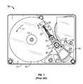
- FIG. 1is a top plan view of a head/disk assembly of a hard disk drive.
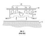
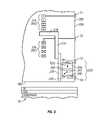
- FIG. 2is an enlarged end view of the slider and a section of the disk taken in the direction 2 - 2 in FIG. 1 .
- FIG. 3is a view in the direction 3 - 3 of FIG. 2 and shows the ends of the read/write head as viewed from the disk.
- FIG. 4Ais a sectional view of a portion of a slider showing a prior art perpendicular write head with a pancake coil and a portion of a perpendicular magnetic recording disk.
- FIG. 4Bis a view in the direction 4 B- 4 B of FIG. 4A and illustrates the flare region of the flared write pole for the perpendicular write head.
- FIG. 5is a side sectional view of a portion of a slider showing a read head, a prior art perpendicular write head with a helical coil, and a perpendicular magnetic recording disk.
- FIG. 6is a schematic illustrating the basic concept of the invention showing a main coil (MC) with main pole, a spin torque oscillator (STO) with its free layer oriented substantially parallel to the main pole, and a flux guide for directing flux from the STO free layer to the main pole in a direction substantially orthogonal to the man pole.
- MCmain coil
- STOspin torque oscillator
- FIG. 7is a graph of a computer-generated micromagnetic simulation of the magnetization reversal of a cylindrical magnetic nanostructure representing the write pole with (Curve B) and without (Curve A) an auxiliary orthogonal field.
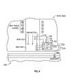
- FIG. 8Ashows an embodiment of the electrical circuitry connected to the main coil (MC) and the STO with separate interconnect lines according to the invention.
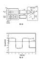
- FIG. 8Bis a graph of the write current (I w ) to the MC and the direct current (I STO ) to the STO for the circuitry embodiment of FIG. 8A .
- FIG. 9shows an embodiment of the invention with the write head main coil (MC) and main pole, and a spin torque oscillator (STO) with its free layer oriented substantially orthogonal to the main pole.
- MCwrite head main coil
- STOspin torque oscillator
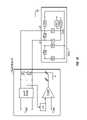
- FIG. 10shows an embodiment of the electrical circuitry connected to the write head (WH) and the STO where the I STO is supplied through the write lines to the WH and thus does not require separate interconnect lines.
- FIG. 11shows an embodiment of the electrical circuitry where the I STO is supplied through the read lines to the read head (RH) and thus does not require separate interconnect lines.
- FIG. 12shows an embodiment of the electrical circuitry for a hard disk drive that has thermal fly-height control (TFC) and where the I STO is supplied through the TFC lines to the heater (HTR) and thus does not require separate interconnect lines.
- TFCthermal fly-height control
- HTRheater
- FIG. 1is a top plan view of a head/disk assembly of a hard disk drive 10 with the cover removed.
- the disk drive 10includes a rigid base 12 supporting a spindle 14 that supports a stack of disks, including top disk 16 .
- the spindle 14is rotated by a spindle motor (not shown) for rotating the disks in the direction shown by curved arrow 17 .
- the hard disk drive 10has at least one load beam assembly 20 having an integrated lead suspension (ILS) or flexure 30 with an array 32 of electrically conductive interconnect traces or lines.
- the load beam assemblies 20are attached to rigid arms 22 connected to an E-shaped support structure, sometimes called an E-block 24 .
- Each flexure 30is attached to an air-bearing slider 28 .
- a magnetic recording read/write head 29is located at the end or trailing surface 25 of slider 28 .
- the flexure 30enables the slider 28 to “pitch” and “roll” on an air-bearing generated by the rotating disk 16 .
- Disk drive 10also includes a rotary actuator assembly 40 rotationally mounted to the rigid base 12 at a pivot point 41 .
- the actuator assembly 40is a voice coil motor (VCM) actuator that includes a magnet assembly 42 fixed to base 12 and a voice coil 43 . When energized by control circuitry (not shown) the voice coil 43 moves and thereby rotates E-block 24 with attached arms 22 and load beam assemblies 20 to position the read/write heads 29 to the data tracks on the disks.
- VCMvoice coil motor
- the trace interconnect array 32connects at one end to the read/write head 29 and at its other end to read/write circuitry contained in an electrical module or chip 50 secured to a side of the E-block 24 .
- the chip 50includes a read preamplifier and a write driver circuit.
- FIG. 2is an enlarged end view of the slider 28 and a section of the disk 16 taken in the direction 2 - 2 in FIG. 1 .
- the slider 28is attached to flexure 30 and has an air-bearing surface (ABS) 27 facing the disk 16 and an end or trailing surface 25 generally perpendicular to the ABS 27 .
- ABS 27causes the airflow from the rotating disk 16 to generate a bearing of air that supports the slider 28 in very close proximity to or near contact with the surface of disk 16 .
- the read/write head 29is formed as a series of thin films deposited on the slider 28 on its trailing surface 25 . Typically a layer of insulating material, like alumina, is deposited over the read/write head 29 and serves as the outer surface of slider 28 .
- the read/write head 29is connected to terminal pads 31 .
- the terminal pads 31connect to the trace array 32 on flexure 30 for electrical connection to the read preamplifier and write driver in chip 50 ( FIG. 1 ).
- FIG. 3is a view in the direction 3 - 3 of FIG. 2 and shows the ends of read/write head 29 as viewed from the disk 16 .
- the read/write head 29includes a read head 96 and a write head 33 that are formed as a series of thin films deposited and lithographically patterned on the trailing surface 25 of slider 28 , with the films of the read head being deposited first and the films of the write head being deposited over the read head.
- the magnetoresistive read sensor or head 96is located between two magnetic shields S 1 and S 2 , with first shield S 1 being located on trailing surface 25 .
- the write head 33has a perpendicular write head and includes magnetic write pole (WP) with WP tip 72 and flux return pole 76 .
- WPmagnetic write pole
- the WP tip 72may be generally surrounded at the ABS by optional side shields 84 and trailing shield 80 .
- the trailing shield 80 and side shields 84may be connected to form a wraparound shield (WAS).
- WASwraparound shield
- the WASis described in detail as a shield for a conventional perpendicular recording head in U.S. Pat. No. 7,002,775 B2 assigned to the same assignee as this application.
- the WASwhich is separated from the WP tip 72 by nonmagnetic gap material, alters the angle of the write field and improves the write field gradient at the point of writing, and also shields the writing field at regions of the disk away from the track being written.
- the shields S 1 , S 2 for the read head 96 and the shields 80 , 84 for the WP tip 72are formed of magnetically permeable material.
- a layer of insulating material, like alumina,is deposited over the write head 33 , resulting in an outer surface 26 .
- the width of the WP tip 72 and the read head 96 in the cross-track directioncorrespond generally to the trackwidth (TW) of the data tracks on the disk 16 .
- FIG. 4Ais a sectional view of a portion of slider 28 showing the perpendicular write head 33 and a portion of a perpendicular magnetic recording disk 16 .
- the disk 16includes a perpendicular magnetic data recording layer (RL) on a “soft” or relatively low-coercivity magnetically permeable underlayer (SUL) formed on the disk substrate.
- the write head 33includes a yoke made up of the main pole 74 , flux return pole 76 , and yoke stud 78 connecting the main pole 74 and flux return pole 76 ; and a thin film “pancake” coil 79 shown as sections wrapped around yoke stud 78 .
- the return pole 76 and yoke stud 78are formed of soft ferromagnetic material, such as alloys of NiFe, CoFe and NiFeCo that are typically formed by electroplating.
- the write head 33 in FIG. 4Ais depicted without the optional WAS ( FIG. 3 ).
- the coil 79is connected to terminals, such as terminal 31 , on the outer surface 26 of slider 28 .
- a flared write pole (WP) 70is part of the main pole 74 and has a flared portion 71 and a pole tip 72 that faces the surface of disk 16 .
- the WP 70is formed of a high-moment material, such as a high-moment CoFe alloy, that is typically formed by sputter deposition, and may be a laminated structure.
- Write current through the thin film coil 79induces a magnetic field (shown by dashed line 90 ) from the flared WP 70 that passes through the data RL (to magnetize the region of the RL beneath the WP 70 ), through the flux return path provided by the SUL, and back to the return pole 76 .
- the slider 28has its air-bearing surface (ABS) 27 supported above the surface of disk 16 as the disk 16 moves past the write head 33 in the direction indicated by arrow 100 .
- ABSair-bearing surface
- the RLis illustrated with a perpendicularly recorded or magnetized region representing data adjacent to the pole tip 72 . Preceding regions are shown having random prerecorded magnetization directions, as represented by the arrows. The magnetic transitions are detectable by the read head (not shown in FIG. 4A ) as the recorded bits.
- the write coil 79is called a “pancake” coil because it is deposited and patterned on the trailing end of the slider as essentially a single layer and thus all of the coil turns lie in substantially the same plane. When write current from the write driver in chip 50 ( FIG. 1 ) is directed to coil 79 in one direction, for example in FIG.
- the region of the RL beneath the WP tip 72is magnetized in one direction, down or into the disk in FIG. 4A .
- the write driverswitches the direction of the write current to coil 79
- the region of the RL beneath the WP tip 72is magnetized in the opposite direction, i.e., up or out of the disk in FIG. 4A .
- FIG. 4Bis a view in the direction 4 B- 4 B of FIG. 4A and illustrates the flare region 71 of the flared WP 70 .
- the region between the WP tip 72 and the flare portion 71is called the flare point 75 .
- the flare point 75 of the WP 70is sometimes referred to as the “choke” point because it is the point where the flux density is highest and where the WP 70 saturates.
- the WP tip 72has its primary or perpendicular axis oriented perpendicular to the ABS and has a “height” or distance from the ABS to flare point 75 called the throat height (TH).
- the two side walls of WP tip 72define its width in the cross-track direction, which substantially defines the trackwidth (TW) of the data recorded in the RL of disk 16 .
- the perpendicular write head of FIG. 4Ahas a “pancake” coil 79 .
- FIG. 5shows slider 28 with trailing surface 25 , outer surface 26 and a read head 96 between shields S 1 , S 2 like that in FIGS. 4A-4B , but wherein the perpendicular write head 133 has a thin film “helical” coil (shown with coil sections 139 a , 139 b ) wrapped around the main pole 74 .
- a perpendicular write head with a helical coilis described in US 2008/0186628 A1 assigned to the same assignee as this application.
- the write head 133is formed on slider 28 having an outer surface 26 and also includes a yoke made up of the main pole 74 , a shield layer 135 , and connection stud 137 to the main pole 74 .
- Pole 136is the return path for the magnetic flux 90 and is connected to trailing shield 150 , which may be part of a WAS.
- Return pole 136has a yoke stud 138 that connects the return pole 136 to the main pole 74 .
- a flared WP 70is part of the main pole 74 and has a flared portion 71 and a WP tip 72 like that shown in FIGS. 4A-4B .
- Write current through coil 139 a , 139 binduces a magnetic field (shown by dashed line 90 ) from the WP 70 that passes through the RL (to magnetize the region of the RL beneath the WP tip 72 ), through the flux return path provided by the SUL, and back to the return pole 136 .
- the end of WP tip 72is located substantially at the ABS, and the return pole 136 has an end 136 a that is located substantially at the ABS and thus generally coplanar with end WP tip 72 .
- a spin torque oscillatoris used to inject magnetic flux into the main pole at an angle, preferably substantially orthogonal, to the primary axis of the main pole.
- the write flux from the main poleflows in a direction perpendicular to the ABS, either toward or away from the RL, depending on the direction of write current in the main coil.
- the auxiliary orthogonal field from the STOinjects additional flux non-parallel to the primary magnetization of the main pole, which exerts a relatively large torque on the magnetization of the main pole, thereby facilitating magnetization reversal of the main pole.
- the basic concept of the inventionis shown in FIG.
- FIG. 6which illustrates the main coil (MC) and main pole with write flux directed perpendicular to the RL of the disk and the STO with auxiliary flux directed through a flux guide at an angle (greater than 15 degrees) and preferably substantially orthogonal (70 to 90 degrees) to the main pole.
- the STOincludes electrodes 101 , 102 , a pinned ferromagnetic layer 104 having its magnetization direction pinned or fixed, a free ferromagnetic layer 106 having its magnetization 107 free to rotate, and a nonmagnetic spacer layer 108 between the pinned ferromagnetic layer 104 and free ferromagnetic layer 106 .
- the pinned layer 104may have its magnetization 105 direction pinned by being exchange-coupled to an antiferromagnetic layer or pinned by a hard magnetic layer such as CoPtCr magnetic layer.
- the ferromagnetic layers 104 , 106are typically formed of Co, Fe or Ni, one of their alloys, or a multilayer of these materials, such as a CoFe/NiFe bilayer, and the nonmagnetic spacer layer 108 is typically formed of Cu, but may also be formed of other materials like Au, Ag and Cr.
- the free ferromagnetic layer 106is oriented with its plane substantially parallel to the main pole of the write head.
- a flux guide 110is coupled to the free layer 106 and directs flux from the free layer 106 substantially orthogonal to the main pole.
- the flux guide 110may be formed of the same high-moment material used in conventional write poles.
- the layers making up the STOare formed on the slider body after the main pole and MC are formed, using conventional deposition and lithographic techniques well-known in the fabrication of thin film read/write heads.
- the STO illustrated in FIG. 6has a structure similar to a conventional current-perpendicular-to-the-plane (CCP) magnetoresistive read head.
- CCP MR read headsare well-known and described, for example, in U.S. Pat. No. 7,450,350 B2, assigned to the same assignee as this application.
- I STOdirect current
- a critical valueis applied across the electrodes 101 , 102 to induce a spin torque on the magnetization 107 of the free ferromagnetic layer 106 .
- the direct current I STOtransfers spin angular momentum from the pinned layer 104 to the free layer 106 to induce precession of the magnetization 107 of the free layer 106 .
- the frequency of precessiondepends on the properties and thicknesses of the materials making up the STO but for a specific STO the frequency of precession is a function of the value of I STO .
- US 2008/01377224 A1describes this type of STO to generate a high-frequency auxiliary field to the recording layer to assist writing. In the STO of FIG.
- the magnetization 105 of pinned layer 104is generally parallel to the magnetization 107 of free layer 106 , but the magnetization 105 may also be pinned in a direction generally orthogonal to the magnetization 107 of the free layer 106 , like that shown in US 2008/01377224 A1.
- the magnetization 107 of free layer 106 in the absence of I STOis oriented in the plane of layer 106 .
- the magnetization 107may be oriented generally orthogonal to the plane of layer 106 .
- This type of STOalso for write assistance of the recording layer, is described in US 2008/0019040 A1 and the related publication by Zhu et al., “Microwave Assisted Magnetic Recording”, IEEE Transactions on Magnetics , Vol. 44, No. 1, January 2008, pp. 125-131.
- the free layeris a field generation layer (FLG) exchange-coupled to a layer with perpendicular anisotropy (PL), wherein the FGL, PL and the pinned or reference layer have their planes oriented orthogonal to the plane of the recording layer, and the pinned or reference layer has its magnetization oriented perpendicular to the planes of the FGL and PL.
- FLGfield generation layer
- PLperpendicular anisotropy
- FIG. 7shows the computer-generated micromagnetic simulation of the magnetization reversal of a cylindrical magnetic nanostructure representing the write pole.
- the nanostructurehas a normalized magnetization of +1.
- Curve Ashows the attempt to reverse the magnetization to ⁇ 1 by applying a field parallel to the height of the nanostructure at a frequency of 0.5 GHz.
- Curve Athe magnetization is not switched but only reduced to about +0.3 after about 1 ns.
- Curve Bshows the result when the same parallel field is applied together with an auxiliary field orthogonal to the height of the nanostructure.
- the orthogonal auxiliary fieldhad an amplitude equal to 20% of the amplitude of the parallel field and was applied at a frequency of 1.0 GHz, twice the frequency of the parallel field.
- Curve Bthe magnetization is completely switched to ⁇ 1 after about 0.8 ns. Additional simulations at different frequencies for the auxiliary orthogonal field show that higher frequencies improve the switching time even further. For example at a frequency of 6.5 GHz for the auxiliary orthogonal field, the magnetization is switched to ⁇ 1 in about 0.5 ns.
- the frequency of the auxiliary magnetic field from the free layer 106 of the STOcan be selected to be preferably within a range near the ferromagnetic resonance of the magnetic material making up the write pole, which generally implies a frequency higher than the frequency of the main write field.
- the frequency of the auxiliary field from the STOis the frequency of precession of the magnetization 107 and, for a specific STO, is a function of the value of direct current (I STO ) applied across terminals 101 , 102 .
- I STO current rangecan be from the ⁇ A to the low mA range, and the current density then determines the STO frequency, which can be from about 2 to 20 GHz.
- Ferromagnetic resonance in the write polearises from the precession motion of the magnetic material of the write pole in the presence of the auxiliary magnetic field from the STO.
- the auxiliary magnetic field from the STOputs a torque on the magnetization of the magnetic material of the write pole which causes the magnetic moment to precess.
- the resonant frequency of the ferromagnetic precessiondepends on the material properties, including magnetic anisotropy and moment density and the shape of the magnetic structure.
- the ferromagnetic resonance frequencyis typically in the range of about 1-4 GHz.
- auxiliary fields with frequencies lower than the ferromagnetic resonance frequencywill also contribute to the switching of the magnetization of the write pole when applied at appreciable angles relative to the main direction of the magnetic anisotropy of the write pole. If the auxiliary field is at a frequency less than the ferromagnetic resonance frequency, the beneficial effect of the auxiliary field on the switching of the magnetization of the write pole will be dominated by the increase of the magnetic reversal torque in proportion to sin( ⁇ ), where ⁇ is the angle between the local direction of the total field from the main coil and the free layer of the STO and the local direction of the magnetization of the write pole.
- the proportionality of the magnetic torque to sin( ⁇ )also explains why the auxiliary field is useful not only at angles of 90 degrees but at lesser angles, preferably in the range of 15 to 90 degrees, relative to the write pole.
- FIG. 8Ashows an embodiment of the electrical circuitry connected to the main coil (MC) and the STO to generate the auxiliary flux.
- the write driver circuitryis in the read/write integrated circuit of chip 50 ( FIG. 1 ) that is located away from the slider 28 , typically on the E-block 24 ( FIG. 1 ).
- the write driveris connected via interconnect lines on the integrated lead suspension (ILS) to the MC at terminals T 1 , T 2 on the slider 28 .
- the write headhas a resistance R w
- the MChas an inductance L MC
- the term C MCrepresents the parasitic capacitance.
- a STO control circuitis located in the circuitry of chip 50 as an independent signal source.
- the STO control circuitis connected to the STO via interconnect lines separate from the interconnect lines between the write driver and the MC, but also located on the ILS.
- the STO electrodes 101 , 102( FIG. 6 ) are connected to terminals T 3 , T 4 , respectively, on slider 28 .
- the STO control circuitryincludes two circuit blocks, a STO control logic (STO-CL) and a STO control digital-to-analog converter (STO-DAC).
- STO-CLmay be a serial port logic receiver that receives logic signals that are stored in a digital register. The digital register values are then converted into analog signals by the STO-DAC.
- the analog output of the STO-DACsets the STO voltage V STO , which sets the value of I STO , which determines the STO frequency, i.e., the frequency of precession of the magnetization 107 of the STO free layer 106 ( FIG. 6 ).
- FIG. 8Bis a graph of the write current (I w ) to the MC and the direct current I STO to the STO.
- the write currentis depicted as switching from +50 mA to ⁇ 50 mA at a frequency of 250 MHz, which corresponds to a maximum data rate of 500 Mb/sec.
- the auxiliary field from the STOhas a frequency preferably greater than the maximum write frequency, preferably close to the ferromagnetic resonance frequency of the magnetic material of the write pole.
- the value of I STOsets the current density through the STO, which will cause the auxiliary field to have a frequency in the range of about 3 to 6 GHz.
- the inventionis not limited by a specific write head structure.
- the inventionmay be implemented in a write head with a pancake coil, like the head depicted in FIGS. 4A-4B .
- FIG. 9shows an embodiment of the write head of the invention as a modification of a write head with a pancake coil.
- the write headincludes a yoke 278 connected to main pole 274 with write pole 270 , and a pancake coil 279 as the main coil (MC) shown as sections wrapped around yoke 278 .
- the coil 279is connected to terminals T 1 and T 2 on the outer surface 226 of slider 228 .
- the STOis oriented with its layers orthogonal to the write pole 270 .
- the STO layersinclude electrodes 201 , 202 , pinned ferromagnetic layer 204 , spacer layer 208 , and free ferromagnetic layer 206 .
- the electrodes 210 , 202are connected to terminals, T 3 , T 4 , respectively, on outer surface 226 .
- the free ferromagnetic layer 206may have its magnetization in the plane of the layer or perpendicular to the plane of the layer in the absence of I STO .
- the magnetization 207precesses and auxiliary magnetic flux is directed generally orthogonally into the write pole 270 with a frequency corresponding to the precession frequency of the magnetization 107 . While in FIG.
- the write head and STO without a flux guidehave been described with respect to a write head with a pancake coil 279
- the inventionmay be implemented in a write head with a helical coil, like the head depicted in FIG. 6 .
- the STO in FIG. 6would be rotated 90 degrees so that the planes of the layers making up the STO are oriented generally orthogonal to the main pole.
- TMPtrenching material process
- the basic steps in creating a TMP for the STO structureinclude: 1) deposition of a dielectric layer such as alumina (Al 2 O 3 ) on the write pole 270 ; 2) patterning the dielectric (etching); 3) deposition of material such as for the contacts and for the STO material; and 4) chemical-mechanical polishing (CMP) or planarization.
- a dielectric layersuch as alumina (Al 2 O 3 ) on the write pole 270 ; 2) patterning the dielectric (etching); 3) deposition of material such as for the contacts and for the STO material; and 4) chemical-mechanical polishing (CMP) or planarization.
- the STOwould be a similar structure as described in U.S. Pat. No. 7,450,350 B2, but the orientation would be orthogonal to the write pole.
- the insulating layer between the write pole 270 and the STOwill be the alumina, which is deposited after the write pole 270 is formed.
- the TMPwould include multiple passes to create the layered structure of the STO.
- the TMP stepsare generally used in the integrated circuit industry, and an example of this process is described in the article by Kahng, A. B. et al., “Fill for Shallow Trench Isolation CMP”, Computer - Aided Design, 2006. ICCAD '06. IEEE/ACM International Conference on 5-9 Nov. 2006 Page(s): 661-668.
- FIG. 10shows an embodiment of the electrical circuitry connected to the write head (WH) and the STO where the I STO is supplied through the write lines +W and ⁇ W to the WH and thus does not require separate interconnect lines.
- the write driver and STO control circuitryare located on the read/write integrated circuit (IC) chip.
- the I STO currentcan also be created by a low-frequency voltage source (V SBC ) that does not inhibit the high-frequency signals of the STO.
- V SBClow-frequency voltage source
- the STO control circuitryincludes a common-mode voltage feed through the write lines +W and ⁇ W that biases the STO.
- resistors R A and R A ′which are closely matched in resistance and high in value, such that a very small amount of the write current signal is shunted away from the signal path.
- the common-mode voltageis then filtered by the low-pass filter (LPF) and compared with the V SBC voltage at the comparator (COMP).
- LPFlow-pass filter
- COMPcomparator
- the control feedbackthen imposes the V SBC voltage on the common-mode of lines +W and ⁇ W.
- resistors R 1 and R 1 ′sense the common-mode at the receiver and a high-pass filter (HPF) shunts the high-frequency signal content away from the STO, thereby placing the V SBC across the STO.
- HPFhigh-pass filter
- the read head (RH) and a heater (HTR)are also shown formed on the slider.
- FIG. 11shows an embodiment of the electrical circuitry where the I STO is supplied through the read lines +R and ⁇ R to the read head (RH) and thus does not require separate interconnect lines.
- the read amplifier and STO control circuitryare located on the read/write integrated circuit (IC) chip.
- the STO control circuitryincludes a common-mode voltage feed through the read lines +R and ⁇ R that biases the STO.
- the circuitry of FIG. 11operates in a similar manner as FIG. 10 by sensing the common-mode through the resistors R A and R A ′, which are closely matched in resistance and high in value, such that a very little of the read head's bias current is shunted away from the signal path.
- the common-mode voltageis then filtered by the low-pass filter (LBF) and compared with the V SBC voltage at the comparator (COMP).
- LPFlow-pass filter
- COMPcomparator
- the control feedbackthen imposes the V SBC voltage on the common-mode of lines +R and ⁇ R.
- resistors R 0 and R 0 ′sense the common-mode at the receiver, thereby placing the V SBC across the STO.
- FIG. 12shows an embodiment of the electrical circuitry for a hard disk drive that has thermal fly-height control (TFC) and where the I STO is supplied through the TFC heater lines +H and ⁇ H to the heater and thus does not require separate interconnect lines.
- Disk drives with TFCare well-known and use an electrically-resistive heater (HTR) located on the slider near the RH and WH. When current is applied to the heater the heater expands and causes the heads to expand and thus move closer to the disk surface during reading and/or writing.
- a disk drive with TFC and a method for controlling the heateris described in U.S. Pat. No. 7,375,914 B1, assigned to the same assignee as this application.
- the STO control circuitryincludes placing the V SBC voltage on the low line of the TFC bias line.
- an auxiliary ground connection from the STOmay be required, such that the STO is biased between the low line of the TFC and ground of the system.
Landscapes
- Engineering & Computer Science (AREA)
- Chemical & Material Sciences (AREA)
- Crystallography & Structural Chemistry (AREA)
- Power Engineering (AREA)
- Nanotechnology (AREA)
- Physics & Mathematics (AREA)
- Condensed Matter Physics & Semiconductors (AREA)
- General Physics & Mathematics (AREA)
- Manufacturing & Machinery (AREA)
- Magnetic Heads (AREA)
- Recording Or Reproducing By Magnetic Means (AREA)
- Digital Magnetic Recording (AREA)
Abstract
Description
Claims (9)
Priority Applications (2)
| Application Number | Priority Date | Filing Date | Title |
|---|---|---|---|
| US12/542,682US8351155B2 (en) | 2009-08-17 | 2009-08-17 | Perpendicular magnetic recording system with spin torque oscillator and control circuitry for fast switching of write pole magnetization |
| JP2010179416AJP2011040151A (en) | 2009-08-17 | 2010-08-10 | Perpendicular magnetic recording system using spin torque oscillator and control circuit for fast switching of write pole magnetization |
Applications Claiming Priority (1)
| Application Number | Priority Date | Filing Date | Title |
|---|---|---|---|
| US12/542,682US8351155B2 (en) | 2009-08-17 | 2009-08-17 | Perpendicular magnetic recording system with spin torque oscillator and control circuitry for fast switching of write pole magnetization |
Publications (2)
| Publication Number | Publication Date |
|---|---|
| US20110038081A1 US20110038081A1 (en) | 2011-02-17 |
| US8351155B2true US8351155B2 (en) | 2013-01-08 |
Family
ID=43588464
Family Applications (1)
| Application Number | Title | Priority Date | Filing Date |
|---|---|---|---|
| US12/542,682Expired - Fee RelatedUS8351155B2 (en) | 2009-08-17 | 2009-08-17 | Perpendicular magnetic recording system with spin torque oscillator and control circuitry for fast switching of write pole magnetization |
Country Status (2)
| Country | Link |
|---|---|
| US (1) | US8351155B2 (en) |
| JP (1) | JP2011040151A (en) |
Cited By (15)
| Publication number | Priority date | Publication date | Assignee | Title |
|---|---|---|---|---|
| US20120314326A1 (en)* | 2011-06-07 | 2012-12-13 | Kabushiki Kaisha Toshiba | Recording head, disk drive with recording head, and recording method using recording head |
| US20130065086A1 (en)* | 2011-09-12 | 2013-03-14 | Kabushiki Kaisha Toshiba | Reproducing head with spin-torque oscillator, and magnetic recording and reproducing apparatus |
| US8547656B2 (en)* | 2012-02-21 | 2013-10-01 | HGST Netherlands B.V. | Spin-torque oscillator (STO) for microwave-assisted magnetic recording (MAMR) and methods of use thereof |
| US8804263B1 (en) | 2013-08-30 | 2014-08-12 | HGST Netherlands B.V. | DC-offset adjustment for balanced embedded contact sensor |
| CN105206286A (en)* | 2014-06-30 | 2015-12-30 | 株式会社东芝 | Magnetic disk apparatus |
| US9286916B1 (en) | 2014-08-26 | 2016-03-15 | Seagate Technology Llc | High frequency data writer field generator device |
| US9311945B2 (en) | 2013-11-06 | 2016-04-12 | HGST Netherlands B.V. | Magnetic head for microwave assisted magnetic recording |
| US9799351B1 (en) | 2015-11-30 | 2017-10-24 | Western Digital (Fremont), Llc | Short yoke length writer having assist coils |
| US10366714B1 (en) | 2016-04-28 | 2019-07-30 | Western Digital Technologies, Inc. | Magnetic write head for providing spin-torque-assisted write field enhancement |
| US10388305B1 (en) | 2016-12-30 | 2019-08-20 | Western Digital Technologies, Inc. | Apparatus and method for writing to magnetic media using an AC bias current to enhance the write field |
| US10424323B1 (en) | 2016-12-30 | 2019-09-24 | Western Digital Technologies, Inc. | High-bandwidth STO bias architecture with integrated slider voltage potential control |
| CN110910909A (en)* | 2018-09-18 | 2020-03-24 | 株式会社东芝 | Magnetic recording/reproducing apparatus |
| US10957346B2 (en) | 2019-05-03 | 2021-03-23 | Western Digital Technologies, Inc. | Magnetic recording devices and methods using a write-field-enhancement structure and bias current with offset pulses |
| US11011190B2 (en) | 2019-04-24 | 2021-05-18 | Western Digital Technologies, Inc. | Magnetic write head with write-field enhancement structure including a magnetic notch |
| US11087784B2 (en) | 2019-05-03 | 2021-08-10 | Western Digital Technologies, Inc. | Data storage devices with integrated slider voltage potential control |
Families Citing this family (25)
| Publication number | Priority date | Publication date | Assignee | Title |
|---|---|---|---|---|
| JP5377893B2 (en)* | 2008-06-19 | 2013-12-25 | 株式会社東芝 | Magnetic head assembly and magnetic recording / reproducing apparatus |
| JP5142923B2 (en)* | 2008-09-30 | 2013-02-13 | 株式会社東芝 | Magnetic oscillation element, magnetic sensor, and magnetic recording / reproducing apparatus |
| JP5558365B2 (en)* | 2008-11-10 | 2014-07-23 | 株式会社日立製作所 | Information recording device |
| US8208219B2 (en)* | 2010-11-05 | 2012-06-26 | Headway Technologies, Inc. | Modified field generation layer for microwave assisted magnetic recording |
| JP5581980B2 (en)* | 2010-11-08 | 2014-09-03 | 株式会社日立製作所 | Magnetic recording head and magnetic recording apparatus |
| US8462461B2 (en) | 2011-07-05 | 2013-06-11 | HGST Netherlands B.V. | Spin-torque oscillator (STO) with magnetically damped free layer |
| US8456967B1 (en) | 2011-10-12 | 2013-06-04 | Western Digital (Fremont), Llc | Systems and methods for providing a pole pedestal for microwave assisted magnetic recording |
| US8982502B2 (en) | 2011-12-12 | 2015-03-17 | HGST Netherlands B.V. | Hard disk drive with write assist based on detected conditions |
| US8687318B2 (en)* | 2012-03-13 | 2014-04-01 | Seagate Technology Llc | Recording head coil structure |
| JP2013206476A (en)* | 2012-03-27 | 2013-10-07 | Tdk Corp | Magnetic head and magnetic recording and reproducing device |
| US9030780B2 (en)* | 2012-08-08 | 2015-05-12 | The United States Of America As Represented By The Secretary Of The Army | Method and apparatus for reading a non-volatile memory using a spin torque oscillator |
| US8582240B1 (en) | 2012-08-29 | 2013-11-12 | Headway Technologies, Inc. | Magnetic recording assisted by spin torque oscillator with a radio frequency current bias |
| US8908330B1 (en) | 2012-12-21 | 2014-12-09 | Western Digital Technologies, Inc. | Spin torque oscillator for microwave assisted magnetic recording with optimal geometries |
| US9355654B1 (en) | 2012-12-21 | 2016-05-31 | Western Digital Technologies, Inc. | Spin torque oscillator for microwave assisted magnetic recording with increased damping |
| US8934189B2 (en) | 2013-05-07 | 2015-01-13 | International Business Machines Corporation | Magnetic write head having electrically biasable structures |
| US9390733B2 (en) | 2013-10-10 | 2016-07-12 | HGST Netherlans B.V. | Microwave-assisted magnetic recording (MAMR) head with an inclined and recessed main pole structure |
| US9245617B2 (en) | 2013-12-17 | 2016-01-26 | The United States Of America As Represented By The Secretary Of The Army | Nonvolatile memory cells programable by phase change and method |
| US9202500B2 (en)* | 2013-12-20 | 2015-12-01 | Seagate Technology Llc | Devices having electrodes on the trailing edge surface |
| US8917465B1 (en)* | 2014-06-26 | 2014-12-23 | HGST Netherlands B.V. | Implementing spin torque oscillator power-on oscillation checker using ramped STO bias differentiator in microwave-assisted magnetic recording (MAMR) hard disk drives |
| US9001444B1 (en)* | 2014-06-26 | 2015-04-07 | HGST Netherlands B.V. | Implementing spin torque oscillator power-on oscillation checker for microwave-assisted magnetic recording hard disk drives |
| US9311934B1 (en)* | 2015-07-24 | 2016-04-12 | HGST Netherlands B.V. | Symmetrical STO for oscillation with both polarity bias |
| US9595281B2 (en)* | 2015-08-11 | 2017-03-14 | Western Digital Technologies, Inc. | Tunable contact detection sensitivity to directly measure clearance of protrusions in magnetic recording heads |
| US10157632B1 (en)* | 2017-06-23 | 2018-12-18 | Western Digital Technologies, Inc. | Areal density capability improvement with spin-orbit torque based structures surrounding main pole tip |
| JP2019046512A (en)* | 2017-08-29 | 2019-03-22 | 株式会社東芝 | Magnetic disk device and control method of recording head |
| US10559412B2 (en)* | 2017-12-07 | 2020-02-11 | Tdk Corporation | Magnetoresistance effect device |
Citations (34)
| Publication number | Priority date | Publication date | Assignee | Title |
|---|---|---|---|---|
| JPS5960722A (en) | 1982-09-30 | 1984-04-06 | Fujitsu Ltd | thin film magnetic head |
| US5661612A (en) | 1992-06-26 | 1997-08-26 | Canon Kabushiki Kaisha | Magnetic head driving device and magnetooptical recording apparatus |
| US5869988A (en) | 1997-03-25 | 1999-02-09 | Marvell Technology Group, Ltd. | High speed write driver for inductive heads |
| US6219193B1 (en) | 1998-02-20 | 2001-04-17 | Seagate Technology Llc | Superpositioning microactuator control and write current signals in a disc drive |
| JP2001202601A (en) | 2000-01-20 | 2001-07-27 | Hitachi Ltd | Recorder |
| US6349009B1 (en) | 1998-06-05 | 2002-02-19 | Seagate Technology Llc | Head assembly with integrated write current shaping circuit |
| US20020030928A1 (en) | 2000-02-10 | 2002-03-14 | Richard Hsiao | Magnetic head having write head element with high aspect ration coil |
| US6775099B2 (en) | 2001-07-24 | 2004-08-10 | Hitachi, Ltd. | High gradient-field recording head for perpendicular magnetic recording |
| JP2004227709A (en) | 2003-01-24 | 2004-08-12 | Nippon Hoso Kyokai <Nhk> | Magnetic recording head and magnetic recording device using the same |
| US6785092B2 (en) | 2001-07-24 | 2004-08-31 | Seagate Technology Llc | White head for high anisotropy media |
| US6816339B1 (en) | 2000-01-10 | 2004-11-09 | Seagate Technology Llc | Perpendicular magnetic recording head with longitudinal magnetic field generator to facilitate magnetization switching |
| US6913704B2 (en) | 2000-08-14 | 2005-07-05 | Hitachi Global Storage Technologies Netherlands, B.V. | Magnetic head induction coil fabrication method utilizing aspect ratio dependent etching |
| US6954331B2 (en) | 2001-08-21 | 2005-10-11 | Seagate Technology Llc | Magnetic recording head including spatially-pumped spin wave mode writer |
| US7002775B2 (en) | 2003-09-30 | 2006-02-21 | Hitachi Global Storage Technologies Netherlands B.V. | Head for perpendicular magnetic recording with a shield structure connected to the return pole piece |
| US20060054699A1 (en) | 2004-09-10 | 2006-03-16 | Josef Osterweil | Method and system for a static magnetic read/write head |
| US7070716B2 (en) | 2003-07-28 | 2006-07-04 | Hitachi Global Storage Technologies Netherlands B.V. | Method for providing transverse magnetic bias proximate to a pole tip to speed up the switching time of the pole-tip during the writing operation |
| US7072142B2 (en) | 2003-07-28 | 2006-07-04 | Hitachi Global Storage Technologies Netherlands B.V. | Apparatus for providing transverse magnetic bias proximate to a pole tip to speed up the switching time of the pole-tip during the writing operation |
| US7237320B2 (en) | 2003-12-08 | 2007-07-03 | Hitachi Global Storage Technologies Netherlands B.V. | Methods of orienting an easy axis of a high-aspect ratio write head for improved writing efficiency |
| US7256955B2 (en) | 2004-03-17 | 2007-08-14 | Seagate Technology Llc | High frequency assisted writing |
| US20070253106A1 (en) | 2006-04-28 | 2007-11-01 | Tdk Corporation | Magnetic head apparatus and magnetic recording and reproducing apparatus |
| US20080019040A1 (en) | 2006-07-21 | 2008-01-24 | Xiaochun Zhu | Perpendicular spin-torque-driven magnetic oscillator |
| US20080112078A1 (en) | 2006-11-13 | 2008-05-15 | Hitachi Global Storage Technologies | Write head with self-cross biased pole for high speed magnetic recording |
| US20080112087A1 (en) | 2006-11-14 | 2008-05-15 | Seagate Technology Llc | WAMR writer with an integrated spin momentum transfer driven oscillator for generating a microwave assist field |
| US20080112080A1 (en) | 2006-11-13 | 2008-05-15 | Hitachi Global Storage Technologies | Magnetic write head employing multiple magnetomotive force (MMF) sources |
| US20080117545A1 (en) | 2006-11-20 | 2008-05-22 | Seagate Technology Llc | Data storage system with field assist source |
| US20080137224A1 (en) | 2006-12-06 | 2008-06-12 | Seagate Technology Llc | High frequency field assisted write device |
| US20080151436A1 (en) | 2006-12-21 | 2008-06-26 | Tdk Corporation | Magnetic recording method using ferromagnetic resonance and thin-film magnetic head for using the method |
| US7397633B2 (en) | 2005-03-01 | 2008-07-08 | Seagate Technology, Llc | Writer structure with assisted bias |
| US20080186628A1 (en) | 2007-02-07 | 2008-08-07 | Hitachi Global Storage Technologies | Magnetic write head with helical coil structure using multiple materials |
| US20080273268A1 (en) | 2007-05-02 | 2008-11-06 | Hitachi Global Storage Technologies Netherlands B.V. | Perpendicular magnetic recording write head with coplanar main pole and return poles and magnetic recording system |
| US20090059418A1 (en) | 2007-09-05 | 2009-03-05 | Kabushiki Kaisha Toshiba | Magnetic head and disk drive with high-frequency assisted writing |
| US20090059423A1 (en)* | 2007-09-04 | 2009-03-05 | Kabushiki Kaisha Toshiba | Magnetic recording head and magnetic recording apparatus |
| US20090225465A1 (en)* | 2007-09-11 | 2009-09-10 | Kabushiki Kaisha Toshiba | Magnetic recording head and magnetic recording apparatus |
| US7957098B2 (en)* | 2007-08-22 | 2011-06-07 | Kabushiki Kaisha Toshiba | Magnetic recording head and magnetic recording apparatus |
- 2009
- 2009-08-17USUS12/542,682patent/US8351155B2/ennot_activeExpired - Fee Related
- 2010
- 2010-08-10JPJP2010179416Apatent/JP2011040151A/enactivePending
Patent Citations (34)
| Publication number | Priority date | Publication date | Assignee | Title |
|---|---|---|---|---|
| JPS5960722A (en) | 1982-09-30 | 1984-04-06 | Fujitsu Ltd | thin film magnetic head |
| US5661612A (en) | 1992-06-26 | 1997-08-26 | Canon Kabushiki Kaisha | Magnetic head driving device and magnetooptical recording apparatus |
| US5869988A (en) | 1997-03-25 | 1999-02-09 | Marvell Technology Group, Ltd. | High speed write driver for inductive heads |
| US6219193B1 (en) | 1998-02-20 | 2001-04-17 | Seagate Technology Llc | Superpositioning microactuator control and write current signals in a disc drive |
| US6349009B1 (en) | 1998-06-05 | 2002-02-19 | Seagate Technology Llc | Head assembly with integrated write current shaping circuit |
| US6816339B1 (en) | 2000-01-10 | 2004-11-09 | Seagate Technology Llc | Perpendicular magnetic recording head with longitudinal magnetic field generator to facilitate magnetization switching |
| JP2001202601A (en) | 2000-01-20 | 2001-07-27 | Hitachi Ltd | Recorder |
| US20020030928A1 (en) | 2000-02-10 | 2002-03-14 | Richard Hsiao | Magnetic head having write head element with high aspect ration coil |
| US6913704B2 (en) | 2000-08-14 | 2005-07-05 | Hitachi Global Storage Technologies Netherlands, B.V. | Magnetic head induction coil fabrication method utilizing aspect ratio dependent etching |
| US6785092B2 (en) | 2001-07-24 | 2004-08-31 | Seagate Technology Llc | White head for high anisotropy media |
| US6775099B2 (en) | 2001-07-24 | 2004-08-10 | Hitachi, Ltd. | High gradient-field recording head for perpendicular magnetic recording |
| US6954331B2 (en) | 2001-08-21 | 2005-10-11 | Seagate Technology Llc | Magnetic recording head including spatially-pumped spin wave mode writer |
| JP2004227709A (en) | 2003-01-24 | 2004-08-12 | Nippon Hoso Kyokai <Nhk> | Magnetic recording head and magnetic recording device using the same |
| US7072142B2 (en) | 2003-07-28 | 2006-07-04 | Hitachi Global Storage Technologies Netherlands B.V. | Apparatus for providing transverse magnetic bias proximate to a pole tip to speed up the switching time of the pole-tip during the writing operation |
| US7070716B2 (en) | 2003-07-28 | 2006-07-04 | Hitachi Global Storage Technologies Netherlands B.V. | Method for providing transverse magnetic bias proximate to a pole tip to speed up the switching time of the pole-tip during the writing operation |
| US7002775B2 (en) | 2003-09-30 | 2006-02-21 | Hitachi Global Storage Technologies Netherlands B.V. | Head for perpendicular magnetic recording with a shield structure connected to the return pole piece |
| US7237320B2 (en) | 2003-12-08 | 2007-07-03 | Hitachi Global Storage Technologies Netherlands B.V. | Methods of orienting an easy axis of a high-aspect ratio write head for improved writing efficiency |
| US7256955B2 (en) | 2004-03-17 | 2007-08-14 | Seagate Technology Llc | High frequency assisted writing |
| US20060054699A1 (en) | 2004-09-10 | 2006-03-16 | Josef Osterweil | Method and system for a static magnetic read/write head |
| US7397633B2 (en) | 2005-03-01 | 2008-07-08 | Seagate Technology, Llc | Writer structure with assisted bias |
| US20070253106A1 (en) | 2006-04-28 | 2007-11-01 | Tdk Corporation | Magnetic head apparatus and magnetic recording and reproducing apparatus |
| US20080019040A1 (en) | 2006-07-21 | 2008-01-24 | Xiaochun Zhu | Perpendicular spin-torque-driven magnetic oscillator |
| US20080112078A1 (en) | 2006-11-13 | 2008-05-15 | Hitachi Global Storage Technologies | Write head with self-cross biased pole for high speed magnetic recording |
| US20080112080A1 (en) | 2006-11-13 | 2008-05-15 | Hitachi Global Storage Technologies | Magnetic write head employing multiple magnetomotive force (MMF) sources |
| US20080112087A1 (en) | 2006-11-14 | 2008-05-15 | Seagate Technology Llc | WAMR writer with an integrated spin momentum transfer driven oscillator for generating a microwave assist field |
| US20080117545A1 (en) | 2006-11-20 | 2008-05-22 | Seagate Technology Llc | Data storage system with field assist source |
| US20080137224A1 (en) | 2006-12-06 | 2008-06-12 | Seagate Technology Llc | High frequency field assisted write device |
| US20080151436A1 (en) | 2006-12-21 | 2008-06-26 | Tdk Corporation | Magnetic recording method using ferromagnetic resonance and thin-film magnetic head for using the method |
| US20080186628A1 (en) | 2007-02-07 | 2008-08-07 | Hitachi Global Storage Technologies | Magnetic write head with helical coil structure using multiple materials |
| US20080273268A1 (en) | 2007-05-02 | 2008-11-06 | Hitachi Global Storage Technologies Netherlands B.V. | Perpendicular magnetic recording write head with coplanar main pole and return poles and magnetic recording system |
| US7957098B2 (en)* | 2007-08-22 | 2011-06-07 | Kabushiki Kaisha Toshiba | Magnetic recording head and magnetic recording apparatus |
| US20090059423A1 (en)* | 2007-09-04 | 2009-03-05 | Kabushiki Kaisha Toshiba | Magnetic recording head and magnetic recording apparatus |
| US20090059418A1 (en) | 2007-09-05 | 2009-03-05 | Kabushiki Kaisha Toshiba | Magnetic head and disk drive with high-frequency assisted writing |
| US20090225465A1 (en)* | 2007-09-11 | 2009-09-10 | Kabushiki Kaisha Toshiba | Magnetic recording head and magnetic recording apparatus |
Non-Patent Citations (4)
| Title |
|---|
| Kahng, A.B. et al., "Fill for Shallow Trench Isolation CMP", Computer-Aided Design, 2006. ICCAD '06. IEEE/ACM International Conference on Nov. 5-9, 2006 pp. 661-668. |
| Kittel C., "On the Theory of Ferromagnetic Resonance Absorption", Phys. Rev. 73, p. 155-161 (1948). |
| Zhu, J. G. et al., "Microwave assisted recording", IEEE Trans. Mag. (2008), pp. 125-131. |
| Zhu, X. et al., "Bias-Field-Free Microwave Oscillator Driven by Perpendicularly Polarized Spin Current", IEEE Transactions on Magnetics, vol. 42, No. 10, Oct. 2006, pp. 2670-2672. |
Cited By (25)
| Publication number | Priority date | Publication date | Assignee | Title |
|---|---|---|---|---|
| US20120314326A1 (en)* | 2011-06-07 | 2012-12-13 | Kabushiki Kaisha Toshiba | Recording head, disk drive with recording head, and recording method using recording head |
| US8467150B2 (en)* | 2011-06-07 | 2013-06-18 | Kabushiki Kaisha Toshiba | Recording head, disk drive with recording head, and recording method using recording head |
| US20130065086A1 (en)* | 2011-09-12 | 2013-03-14 | Kabushiki Kaisha Toshiba | Reproducing head with spin-torque oscillator, and magnetic recording and reproducing apparatus |
| US8755153B2 (en)* | 2011-09-12 | 2014-06-17 | Kabushiki Kaisha Toshiba | Reproducing head with spin-torque oscillator, and magnetic recording and reproducing apparatus |
| US8547656B2 (en)* | 2012-02-21 | 2013-10-01 | HGST Netherlands B.V. | Spin-torque oscillator (STO) for microwave-assisted magnetic recording (MAMR) and methods of use thereof |
| US8804263B1 (en) | 2013-08-30 | 2014-08-12 | HGST Netherlands B.V. | DC-offset adjustment for balanced embedded contact sensor |
| US9311945B2 (en) | 2013-11-06 | 2016-04-12 | HGST Netherlands B.V. | Magnetic head for microwave assisted magnetic recording |
| CN105206286A (en)* | 2014-06-30 | 2015-12-30 | 株式会社东芝 | Magnetic disk apparatus |
| CN105206286B (en)* | 2014-06-30 | 2018-04-17 | 株式会社东芝 | Disk set |
| US9286916B1 (en) | 2014-08-26 | 2016-03-15 | Seagate Technology Llc | High frequency data writer field generator device |
| US9799351B1 (en) | 2015-11-30 | 2017-10-24 | Western Digital (Fremont), Llc | Short yoke length writer having assist coils |
| US10811039B2 (en) | 2016-04-28 | 2020-10-20 | Western Digital Technologies, Inc. | Magnetic write head for providing spin-torque-assisted write field enhancement |
| US10546603B2 (en) | 2016-04-28 | 2020-01-28 | Western Digital Technologies, Inc. | Magnetic write head for providing spin-torque-assisted write field enhancement |
| US10366714B1 (en) | 2016-04-28 | 2019-07-30 | Western Digital Technologies, Inc. | Magnetic write head for providing spin-torque-assisted write field enhancement |
| US10891973B2 (en) | 2016-12-30 | 2021-01-12 | Western Digital Technologies, Inc. | High-bandwidth STO bias architecture with integrated slider voltage potential control |
| US10424323B1 (en) | 2016-12-30 | 2019-09-24 | Western Digital Technologies, Inc. | High-bandwidth STO bias architecture with integrated slider voltage potential control |
| US10388305B1 (en) | 2016-12-30 | 2019-08-20 | Western Digital Technologies, Inc. | Apparatus and method for writing to magnetic media using an AC bias current to enhance the write field |
| US10629229B2 (en) | 2016-12-30 | 2020-04-21 | Western Digital Technologies, Inc. | High-bandwidth STO bias architecture with integrated slider voltage potential control |
| US10643642B2 (en) | 2016-12-30 | 2020-05-05 | Western Digital Technologies, Inc. | Apparatus and method for writing to magnetic media using an AC bias current to enhance the write field |
| CN110910909A (en)* | 2018-09-18 | 2020-03-24 | 株式会社东芝 | Magnetic recording/reproducing apparatus |
| CN110910909B (en)* | 2018-09-18 | 2021-07-13 | 株式会社东芝 | Magnetic recording and reproducing device |
| US11011190B2 (en) | 2019-04-24 | 2021-05-18 | Western Digital Technologies, Inc. | Magnetic write head with write-field enhancement structure including a magnetic notch |
| US10957346B2 (en) | 2019-05-03 | 2021-03-23 | Western Digital Technologies, Inc. | Magnetic recording devices and methods using a write-field-enhancement structure and bias current with offset pulses |
| US11087784B2 (en) | 2019-05-03 | 2021-08-10 | Western Digital Technologies, Inc. | Data storage devices with integrated slider voltage potential control |
| US11276424B2 (en) | 2019-05-03 | 2022-03-15 | Western Digital Technologies, Inc. | Data storage devices with integrated slider voltage potential control |
Also Published As
| Publication number | Publication date |
|---|---|
| JP2011040151A (en) | 2011-02-24 |
| US20110038081A1 (en) | 2011-02-17 |
Similar Documents
| Publication | Publication Date | Title |
|---|---|---|
| US8351155B2 (en) | Perpendicular magnetic recording system with spin torque oscillator and control circuitry for fast switching of write pole magnetization | |
| US8446690B2 (en) | Perpendicular magnetic recording write head with spin torque oscillator for fast switching of write pole magnetization | |
| US10957348B2 (en) | Magnetic recording write head with selected write gap current direction for minimization of cross-track interference | |
| US8116031B2 (en) | Perpendicular magnetic recording system with helical write coil and auxiliary coil for fast switching of write pole magnetization | |
| US8116032B2 (en) | Perpendicular magnetic recording system with auxiliary coil and circuitry for fast switching of write pole magnetization | |
| US10923145B2 (en) | Microwave-assisted magnetic recording (MAMR) write head with compensation for DC shunting field | |
| US7688544B1 (en) | Magnetic heads disk drives and methods with floating pole tip or shunted pole tip for reduced pole tip erasure | |
| US8179633B2 (en) | Perpendicular magnetic recording system and write head with transverse auxiliary pole for fast switching of write pole magnetization | |
| US8654480B2 (en) | Magnetic head with spin torque oscillator and magnetic recording head | |
| US8164854B2 (en) | Magnetic recording head with spin oscillation device and magnetic recording apparatus including the magnetic recording head | |
| US8154825B2 (en) | Magnetic recording head and magnetic recording device | |
| US8139322B2 (en) | Magnetic recording head with protruding spin torque oscillator | |
| US7791829B2 (en) | Apparatus for assisting write operation using high frequency magnetic field in disk drive | |
| US8320079B2 (en) | Magnetic head assembly and magnetic recording/reproducing apparatus | |
| US7952827B2 (en) | Heat-assisted magnetic recording method using eddy current and head for heat-assisted magnetic recording | |
| US10460752B2 (en) | Spin-torque oscillator with multilayer seed layer between the write pole and the free layer in a magnetic recording write head | |
| US8174937B2 (en) | Thin-film magnetic head having microwave magnetic exciting function and magnetic recording and reproducing apparatus | |
| US10566015B2 (en) | Spin transfer torque (STT) device with template layer for heusler alloy magnetic layers | |
| JP2009301695A (en) | Thin-film magnetic head for microwave assist and microwave-assisted magnetic recording method | |
| CN101320567A (en) | Magnetic recording head and magnetic recording device | |
| US11646052B2 (en) | Spin-torque oscillator with multilayer seed layer between the write pole and the free layer in a magnetic recording write head | |
| US9741373B1 (en) | Microwave assisted magnetic head, head gimbal assembly, and magnetic recording device | |
| JPH1049837A (en) | Magnetic recording / reproducing device | |
| JP2005159370A (en) | Magnetoresistance effect element, magnetoresistance effect head, magnetoresistance conversion system and magnetic recording system |
Legal Events
| Date | Code | Title | Description |
|---|---|---|---|
| AS | Assignment | Owner name:HITACHI GLOBAL STORAGE TECHNOLOGIES NETHERLANDS B. Free format text:ASSIGNMENT OF ASSIGNORS INTEREST;ASSIGNORS:CONTRERAS, JOHN THOMAS;SCHABES, MANFRED ERNST;SIGNING DATES FROM 20090622 TO 20090708;REEL/FRAME:023108/0393 | |
| FEPP | Fee payment procedure | Free format text:PAYOR NUMBER ASSIGNED (ORIGINAL EVENT CODE: ASPN); ENTITY STATUS OF PATENT OWNER: LARGE ENTITY | |
| AS | Assignment | Owner name:HGST, NETHERLANDS B.V., NETHERLANDS Free format text:CHANGE OF NAME;ASSIGNOR:HGST, NETHERLANDS B.V.;REEL/FRAME:029341/0777 Effective date:20120723 Owner name:HGST NETHERLANDS B.V., NETHERLANDS Free format text:CHANGE OF NAME;ASSIGNOR:HITACHI GLOBAL STORAGE TECHNOLOGIES NETHERLANDS B.V.;REEL/FRAME:029341/0777 Effective date:20120723 | |
| STCF | Information on status: patent grant | Free format text:PATENTED CASE | |
| CC | Certificate of correction | ||
| FPAY | Fee payment | Year of fee payment:4 | |
| AS | Assignment | Owner name:WESTERN DIGITAL TECHNOLOGIES, INC., CALIFORNIA Free format text:ASSIGNMENT OF ASSIGNORS INTEREST;ASSIGNOR:HGST NETHERLANDS B.V.;REEL/FRAME:040826/0821 Effective date:20160831 | |
| AS | Assignment | Owner name:JPMORGAN CHASE BANK, N.A., AS AGENT, ILLINOIS Free format text:SECURITY INTEREST;ASSIGNOR:WESTERN DIGITAL TECHNOLOGIES, INC.;REEL/FRAME:052915/0566 Effective date:20200113 | |
| MAFP | Maintenance fee payment | Free format text:PAYMENT OF MAINTENANCE FEE, 8TH YEAR, LARGE ENTITY (ORIGINAL EVENT CODE: M1552); ENTITY STATUS OF PATENT OWNER: LARGE ENTITY Year of fee payment:8 | |
| AS | Assignment | Owner name:WESTERN DIGITAL TECHNOLOGIES, INC., CALIFORNIA Free format text:RELEASE OF SECURITY INTEREST AT REEL 052915 FRAME 0566;ASSIGNOR:JPMORGAN CHASE BANK, N.A.;REEL/FRAME:059127/0001 Effective date:20220203 | |
| AS | Assignment | Owner name:JPMORGAN CHASE BANK, N.A., ILLINOIS Free format text:PATENT COLLATERAL AGREEMENT - A&R LOAN AGREEMENT;ASSIGNOR:WESTERN DIGITAL TECHNOLOGIES, INC.;REEL/FRAME:064715/0001 Effective date:20230818 Owner name:JPMORGAN CHASE BANK, N.A., ILLINOIS Free format text:PATENT COLLATERAL AGREEMENT - DDTL LOAN AGREEMENT;ASSIGNOR:WESTERN DIGITAL TECHNOLOGIES, INC.;REEL/FRAME:067045/0156 Effective date:20230818 | |
| FEPP | Fee payment procedure | Free format text:MAINTENANCE FEE REMINDER MAILED (ORIGINAL EVENT CODE: REM.); ENTITY STATUS OF PATENT OWNER: LARGE ENTITY | |
| LAPS | Lapse for failure to pay maintenance fees | Free format text:PATENT EXPIRED FOR FAILURE TO PAY MAINTENANCE FEES (ORIGINAL EVENT CODE: EXP.); ENTITY STATUS OF PATENT OWNER: LARGE ENTITY | |
| STCH | Information on status: patent discontinuation | Free format text:PATENT EXPIRED DUE TO NONPAYMENT OF MAINTENANCE FEES UNDER 37 CFR 1.362 | |
| FP | Lapsed due to failure to pay maintenance fee | Effective date:20250108 |