US8350827B2 - Display with infrared backlight source and multi-touch sensing function - Google Patents
Display with infrared backlight source and multi-touch sensing functionDownload PDFInfo
- Publication number
- US8350827B2 US8350827B2US11/888,143US88814307AUS8350827B2US 8350827 B2US8350827 B2US 8350827B2US 88814307 AUS88814307 AUS 88814307AUS 8350827 B2US8350827 B2US 8350827B2
- Authority
- US
- United States
- Prior art keywords
- touch
- infrared light
- sensing
- thin
- pixel
- Prior art date
- Legal status (The legal status is an assumption and is not a legal conclusion. Google has not performed a legal analysis and makes no representation as to the accuracy of the status listed.)
- Active, expires
Links
Images


Classifications
- G—PHYSICS
- G02—OPTICS
- G02F—OPTICAL DEVICES OR ARRANGEMENTS FOR THE CONTROL OF LIGHT BY MODIFICATION OF THE OPTICAL PROPERTIES OF THE MEDIA OF THE ELEMENTS INVOLVED THEREIN; NON-LINEAR OPTICS; FREQUENCY-CHANGING OF LIGHT; OPTICAL LOGIC ELEMENTS; OPTICAL ANALOGUE/DIGITAL CONVERTERS
- G02F1/00—Devices or arrangements for the control of the intensity, colour, phase, polarisation or direction of light arriving from an independent light source, e.g. switching, gating or modulating; Non-linear optics
- G02F1/01—Devices or arrangements for the control of the intensity, colour, phase, polarisation or direction of light arriving from an independent light source, e.g. switching, gating or modulating; Non-linear optics for the control of the intensity, phase, polarisation or colour
- G02F1/13—Devices or arrangements for the control of the intensity, colour, phase, polarisation or direction of light arriving from an independent light source, e.g. switching, gating or modulating; Non-linear optics for the control of the intensity, phase, polarisation or colour based on liquid crystals, e.g. single liquid crystal display cells
- G02F1/133—Constructional arrangements; Operation of liquid crystal cells; Circuit arrangements
- G02F1/13306—Circuit arrangements or driving methods for the control of single liquid crystal cells
- G02F1/13312—Circuits comprising photodetectors for purposes other than feedback
- G—PHYSICS
- G02—OPTICS
- G02F—OPTICAL DEVICES OR ARRANGEMENTS FOR THE CONTROL OF LIGHT BY MODIFICATION OF THE OPTICAL PROPERTIES OF THE MEDIA OF THE ELEMENTS INVOLVED THEREIN; NON-LINEAR OPTICS; FREQUENCY-CHANGING OF LIGHT; OPTICAL LOGIC ELEMENTS; OPTICAL ANALOGUE/DIGITAL CONVERTERS
- G02F1/00—Devices or arrangements for the control of the intensity, colour, phase, polarisation or direction of light arriving from an independent light source, e.g. switching, gating or modulating; Non-linear optics
- G02F1/01—Devices or arrangements for the control of the intensity, colour, phase, polarisation or direction of light arriving from an independent light source, e.g. switching, gating or modulating; Non-linear optics for the control of the intensity, phase, polarisation or colour
- G02F1/13—Devices or arrangements for the control of the intensity, colour, phase, polarisation or direction of light arriving from an independent light source, e.g. switching, gating or modulating; Non-linear optics for the control of the intensity, phase, polarisation or colour based on liquid crystals, e.g. single liquid crystal display cells
- G02F1/133—Constructional arrangements; Operation of liquid crystal cells; Circuit arrangements
- G02F1/136—Liquid crystal cells structurally associated with a semi-conducting layer or substrate, e.g. cells forming part of an integrated circuit
- G02F1/1362—Active matrix addressed cells
- G02F1/1368—Active matrix addressed cells in which the switching element is a three-electrode device
- G—PHYSICS
- G06—COMPUTING OR CALCULATING; COUNTING
- G06F—ELECTRIC DIGITAL DATA PROCESSING
- G06F3/00—Input arrangements for transferring data to be processed into a form capable of being handled by the computer; Output arrangements for transferring data from processing unit to output unit, e.g. interface arrangements
- G06F3/01—Input arrangements or combined input and output arrangements for interaction between user and computer
- G06F3/03—Arrangements for converting the position or the displacement of a member into a coded form
- G06F3/041—Digitisers, e.g. for touch screens or touch pads, characterised by the transducing means
- G06F3/0412—Digitisers structurally integrated in a display
- G—PHYSICS
- G06—COMPUTING OR CALCULATING; COUNTING
- G06F—ELECTRIC DIGITAL DATA PROCESSING
- G06F3/00—Input arrangements for transferring data to be processed into a form capable of being handled by the computer; Output arrangements for transferring data from processing unit to output unit, e.g. interface arrangements
- G06F3/01—Input arrangements or combined input and output arrangements for interaction between user and computer
- G06F3/03—Arrangements for converting the position or the displacement of a member into a coded form
- G06F3/041—Digitisers, e.g. for touch screens or touch pads, characterised by the transducing means
- G06F3/042—Digitisers, e.g. for touch screens or touch pads, characterised by the transducing means by opto-electronic means
- G06F3/0421—Digitisers, e.g. for touch screens or touch pads, characterised by the transducing means by opto-electronic means by interrupting or reflecting a light beam, e.g. optical touch-screen
- G—PHYSICS
- G09—EDUCATION; CRYPTOGRAPHY; DISPLAY; ADVERTISING; SEALS
- G09G—ARRANGEMENTS OR CIRCUITS FOR CONTROL OF INDICATING DEVICES USING STATIC MEANS TO PRESENT VARIABLE INFORMATION
- G09G3/00—Control arrangements or circuits, of interest only in connection with visual indicators other than cathode-ray tubes
- G09G3/20—Control arrangements or circuits, of interest only in connection with visual indicators other than cathode-ray tubes for presentation of an assembly of a number of characters, e.g. a page, by composing the assembly by combination of individual elements arranged in a matrix no fixed position being assigned to or needed to be assigned to the individual characters or partial characters
- G09G3/34—Control arrangements or circuits, of interest only in connection with visual indicators other than cathode-ray tubes for presentation of an assembly of a number of characters, e.g. a page, by composing the assembly by combination of individual elements arranged in a matrix no fixed position being assigned to or needed to be assigned to the individual characters or partial characters by control of light from an independent source
- G09G3/36—Control arrangements or circuits, of interest only in connection with visual indicators other than cathode-ray tubes for presentation of an assembly of a number of characters, e.g. a page, by composing the assembly by combination of individual elements arranged in a matrix no fixed position being assigned to or needed to be assigned to the individual characters or partial characters by control of light from an independent source using liquid crystals
- G—PHYSICS
- G02—OPTICS
- G02F—OPTICAL DEVICES OR ARRANGEMENTS FOR THE CONTROL OF LIGHT BY MODIFICATION OF THE OPTICAL PROPERTIES OF THE MEDIA OF THE ELEMENTS INVOLVED THEREIN; NON-LINEAR OPTICS; FREQUENCY-CHANGING OF LIGHT; OPTICAL LOGIC ELEMENTS; OPTICAL ANALOGUE/DIGITAL CONVERTERS
- G02F1/00—Devices or arrangements for the control of the intensity, colour, phase, polarisation or direction of light arriving from an independent light source, e.g. switching, gating or modulating; Non-linear optics
- G02F1/01—Devices or arrangements for the control of the intensity, colour, phase, polarisation or direction of light arriving from an independent light source, e.g. switching, gating or modulating; Non-linear optics for the control of the intensity, phase, polarisation or colour
- G02F1/13—Devices or arrangements for the control of the intensity, colour, phase, polarisation or direction of light arriving from an independent light source, e.g. switching, gating or modulating; Non-linear optics for the control of the intensity, phase, polarisation or colour based on liquid crystals, e.g. single liquid crystal display cells
- G02F1/133—Constructional arrangements; Operation of liquid crystal cells; Circuit arrangements
- G02F1/1333—Constructional arrangements; Manufacturing methods
- G02F1/13338—Input devices, e.g. touch panels
- G—PHYSICS
- G02—OPTICS
- G02F—OPTICAL DEVICES OR ARRANGEMENTS FOR THE CONTROL OF LIGHT BY MODIFICATION OF THE OPTICAL PROPERTIES OF THE MEDIA OF THE ELEMENTS INVOLVED THEREIN; NON-LINEAR OPTICS; FREQUENCY-CHANGING OF LIGHT; OPTICAL LOGIC ELEMENTS; OPTICAL ANALOGUE/DIGITAL CONVERTERS
- G02F2203/00—Function characteristic
- G02F2203/11—Function characteristic involving infrared radiation
Definitions
- the present inventionrelates to a display, and more particularly to a display that is capable of multi-touch sensing, and a driving method thereof.
- a touch panelis a type of user interface that may be attached to a surface of a display device, where an electrical characteristic is changed at a touch area where a finger of the user or other instrument contacts the touch panel so as to sense the touch area thereof.
- the application for touch panelsextend to small portable terminals, office equipment and the like. If two or more touches are simultaneously generated, the touch panel might malfunction or any one of the touches may be selected by a pre-set program.
- FIGS. 1-3show known multi-touch devices that have attempted to overcome the limitations of multi-touch recognition systems.
- the multi-touch device of the related artincludes a transparent acrylic plate 11 and first through fourth IR (infrared) arrays 12 A- 12 D.
- IR arrays 12 A- 12 Dinclude infrared light emitting diodes (IRLED), and IR photo detectors (IRPD).
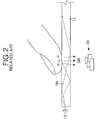
- FIG. 2shows that a hand of the user or a pen is directly in contact with the transparent acrylic plate 11 .
- the first through fourth IR arrays 12 A- 12 Dare arranged to face a side surface of the transparent acrylic plate 11 . Infrared light is radiated from the IRLEDs 13 through the transparent acrylic plate 11 . The infrared light is received by the corresponding IRPDs 14 . In this state, if a finger of the user or a pen is in contact with the transparent acrylic plate 11 , the infrared light is scattered and is not received at the corresponding IRPD 14 . Accordingly, the multi-touch device in FIG. 1 may recognize an erroneous touch location.
- a multi-touch device of the related art in FIG. 1includes the IR arrays 12 A- 12 D arranged at a side surface of the transparent acrylic plate 11 , and is advantageous because it is thin.
- the multi-touch device of the related artis disadvantageous because the multi-touch recognition capability is inaccurate due to a direct illumination by infrared light. Further, the effective display surface is reduced by an area occupied by the IR arrays 12 A- 12 D.
- FIG. 2 and FIG. 3show a projector-type multi-touch device.
- the multi-touch deviceincludes a camera and projector module 30 , which are located a rear portion of the transparent acrylic plate 11 .
- the multi-touch device in FIG. 2 and FIG. 3occupies a wide space. Furthermore, since the multi-touch device in FIG. 2 and FIG. 3 displays an image using a projector, the type of display device and the design of the display device is limited. Additionally, the life span of a the projection lens is limited.
- the multi-touch devices in FIG. 2 and FIG. 3transmit signals from the camera and projector module 30 to an external computer via a cable, and process the signals by the external computer.
- the systemis complicated, the space occupied by the components is large, and a signal transmitting path is long.
- a touch-sensing display screenincludes an upper transparent substrate, a lower substrate opposite the upper substrate, and a backlight unit having an infrared light source configured to radiate infrared light through the upper substrate in a first direction.
- a transparent windowis disposed in alignment with the infrared light source and between the upper and lower transparent substrates. A portion of the infrared light radiated in the first direction is reflected back through the upper substrate and through the transparent window in a second direction by an object touching a surface of the upper transparent substrate.
- a pixel thin-film transistor on the lower substrateis configured to activate a pixel electrode, and an infrared light-sensing thin-film transistor is configured to sense the infrared light received through the upper substrate in the second direction, and output an infrared light-sense signal in response thereto.
- FIG. 1is a plan view schematically showing a multi-touch device of the related art
- FIG. 2 and FIG. 3show related multi-touch devices
- FIG. 4is a sectional view showing a display having a multi-touch sensing function according to an embodiment
- FIG. 5 to FIG. 7are plan views showing an example of a light source arrangement of the backlight unit in FIG. 4 ;
- FIG. 8is a sectional view showing an operation of the display having a multi-touch sensing function in FIG. 4 ;
- FIG. 9is a plan view of a sub-pixel showing an IR TFT
- FIG. 10is a sectional view taken along the lines I-I′ and II-II′ of FIG. 9 ;
- FIG. 11is a plan view showing formation of a black matrix, and an exposed area at the sub-pixel in FIG. 9 ;
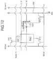
- FIG. 12is an equivalent circuit diagram of the sub-pixel in FIG. 9 ;
- FIG. 13is a block diagram showing the display having a multi-touch sensing function and a driving circuit.
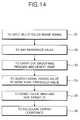
- FIG. 14is a flowchart showing processing of a touch image.
- a display having a multi-touch sensing functionincludes a display panel 40 and a backlight unit 50 having an infrared light source.
- the display panel 40includes an upper transparent substrate 41 , a lower transparent substrate 42 , and a liquid crystal layer LC.
- the upper transparent substrate 41has color filters RCF, GCF, and BCF and a transparent window W, which are formed at the same layer.
- the lower transparent substrate 42has a pixel thin film transistor (TFT) that selects a pixel, and a TFT for sensing an infrared ray (IR TFT).
- TFTpixel thin film transistor
- IR TFTinfrared ray
- the liquid crystal layer LCis formed between the upper transparent substrate 41 and the lower transparent substrate 42 . It is desirable that the upper/lower transparent substrates 41 and 42 are formed of a glass substrate because a plastic substrate, such as an acrylic plate, is relatively thick, has a wide diffusing angle upon touching, and is easily damaged or scratched.
- a plurality of data lines and a plurality of gate linescross each other on the lower transparent substrate 42 , as shown in FIG. 9 .
- a plurality of driving voltage supply linesare parallel to the gate lines, and a plurality of read-out lines, which cross the gate lines and the driving voltage supply lines, are formed on the lower transparent substrate 42 , as shown in FIG. 9 .
- the TFTs for selecting a pixelare formed at the intersection of the data lines and the gate lines on the lower transparent substrate 42 .
- the IR TFTare formed at the intersection of the driving voltage supply lines and the read-out lines on the lower transparent substrate 42 .
- the pixel electrodesare formed on the lower transparent substrate 42 , and are connected to the TFTs.
- the TFTs for selecting a pixelsupply a data voltage from the data line to the pixel electrode in response to a scanning signal from the gate line.
- the IR TFTssense a portion of the infrared light reflected via the upper transparent substrate 41 and the transparent window W from the touch point.
- the IR TFTsoutput the infrared light sensing signal via the read-out line. It is not necessary to have an IR TFT for each pixel. Thus, there may be only one IR TFT for each N number of pixels, where the number N is a selected design parameter. The number of pixels between each of the IR TFTs may be adjusted.
- the color filters RCF, GCF, and BCF and the transparent window Ware formed on the upper transparent substrate 41 .
- a common electrodeis formed on the upper transparent substrate 41 , and is disposed opposite a pixel electrode with the liquid crystal layer LC therebetween.
- the common electrodeis supplied with a common voltage according to a vertical electric field application, such as a Twisted Nematic (TN) mode or a Vertical Alignment (VA) mode.
- the common electrodemay be formed on the lower transparent substrate 42 according to a horizontal electric field application method, such as an In-Plane Switching IPS mode and a Fringe Field Switching FFS mode.
- the backlight unit 50includes a red light source RLED, a green light source GLED, a blue light source BLED, and an infrared light source IRLED.
- the light sourcesare provided by LEDs.
- the backlight unit 50includes optical components, such as a diffusion plate, at least one diffusion sheet, and at least one prism sheet. The optical components are located between the lower transparent substrate 42 and the light sources RLED, GLED, BLED, and IRLED.
- a reflecting materialmay be located on each of the red light source, the green light source, and the blue light source RLED, GLED, and BLED. Red light, green light, and blue light are reflected due to the reflecting material. The red light, the green light, and the blue light mix to form white light within an air space between the light sources and the lower transparent substrate 42 . The white light radiates toward the display panel 40 .
- the infrared light source IRLEDradiates infrared light to the lower glass substrate 42 through the air space. It is not necessary to include an infrared light source IRLED for each pixel. There may be only one infrared light source IRLED for each N pixels, where the number N is a selected design parameter. An intensity of the infrared light source IRLED is adjusted so that the infrared light may be reflected from a non-transmitting object, for example, a finger, tool, or other instrument, which is in contact with the upper transparent substrate 41 .
- the reflected infrared lightmay be received by the IR TFT.
- an intensity of the infrared light source IRLEDis adjusted to be reflected within about twelve millimeters that defines a thickness of a liquid crystal module including the display panel 40 and the backlight unit 50 .
- the light sources RLED, GLED, BLED, and IRLEDmay be arranged in a plurality of rows as a repeating sequence of a red light, a green lights, a blue light and an IR light, as shown in FIG. 5 .
- An arrangement interval and the number of the infrared light sources IR LEDmay be adjusted in accordance with a receiving characteristics of the infrared components.
- the light sources of the backlight unit 50may be include white LEDs and IRLEDs, or a plurality of fluorescent lamps and IRLEDs in a hybrid configuration, as shown in FIGS. 6 and 7 .
- FIG. 8shows a multi-touch operation of the liquid crystal device having a multi-touch sensing function. If a finger or a other non-transmitting object contacts the upper transparent substrate 41 when the display panel 40 is energized, infrared light is reflected from the contact surface and is received by the IR TFT. A digital signal processing circuit processes and analyzes the infrared light received by the IR TFT. As a result, a coordinate value corresponding to the touch point is calculated, and the a plurality of touch points are recognized and identified. At the same time, one or more touch images corresponding to the touch points are displayed on the display panel 40 .
- FIG. 9 to FIG. 12are diagrams for explaining a structure and an operation of a sub-pixel where the IR TFT is formed.
- the lower transparent substrate 42 of the display panel 40includes a gate line (or a scanning line) GL, a data line DL, a first TFT TFT 1 , a pixel electrode PXLE, a read-out line ROL, a first and second driving voltage supply lines VL 1 and VL 2 , a IR TFT, and a second TFT TFT 2 .
- the gate line GL and the data line DLcross each other with a gate insulating film 101 therebetween.
- the first TFT TFT 1is formed at each intersection of the gate line GL and the data line DL.
- the pixel electrode PXLEis formed at a cell area defined by the intersection of the gate line GL and the data line DL.
- the read-out line ROLis formed parallel to the data line DL with the pixel electrode PXLE therebetween.
- the first and second driving voltage supply lines VL 1 and VL 2are formed parallel to the gate line GL and supply first and second driving voltages.
- the IR TFTis formed at an intersection of the first driving voltage supply line VL 1 and the second TFT TFT 2 .
- the second TFT TFT 2is formed at an intersection of the gate line GL and the read-out line ROL.
- the lower transparent substrate 42 of the display panel 40includes a first storage capacitor Cst 1 and a second storage capacitor Cst 2 .
- the first storage capacitor Cst 1is electrically connected to the second driving voltage supply line VL 2 between the IR TFT and the second TFT TFT 2 .
- the second storage capacitor Cst 2is formed at an overlapping area of the pixel electrode PXLE and the pre-stage gate line GL.
- the first TFT TFT 1includes a gate electrode GE, a source electrode SE, a drain electrode DE, and an active layer 102 .
- the gate electrode GEis connected to the gate line GL.
- the source electrode SEis connected to the data line DL.
- the drain electrode DEis connected to the pixel electrode PXLE.
- the active layer 102is overlapped with the gate electrode GE and forms a channel between the source electrode SE and the drain electrode DE.
- the active layer 102is overlapped with the data line DL, the source electrode SE, and the drain electrode DE.
- An ohmic contact layer 103which makes an ohmic contact with the source electrode SE and the drain electrode DE, is formed on the active layer 102 .
- the active layer 102is formed from amorphous silicon A-Si:H or a polysilicon. Such an active layer 102 and an ohmic contact layer 103 are patterned as a semiconductor pattern SCP.
- the first TFT TFT 1is turned-on by a high voltage of a gate signal (or a scanning signal) from the gate line GL and provides a data voltage from the data line DL to the pixel electrode PXLE.
- a gate high-voltageis a voltage greater than a threshold voltage of the first TFT TFT 1 .
- a low logical voltage of a gate signalis a voltage less than a threshold voltage of the first TFT TFT 1 .
- the pixel electrode PXLEis a transparent electrode such as an Indium Tin Oxide ITO.
- the pixel electrode PXLEis connected via a first contact hole 109 , which passes through a protective film 104 , to the drain electrode DE of the first TFT TFT 1 .
- a data voltageis applied to the pixel electrode, a potential difference is generated between the pixel electrode PXLE and a common electrode.
- the common electrodeis formed at the upper transparent substrate 41 or the lower transparent substrate 42 . Liquid crystal molecules are rotated due to the potential difference therebetween to change refractivity of a light, which is emitted by the backlight unit 50 .
- the second storage capacitor Cst 2is formed by the pre-stage gate line GL and the pixel electrode PXLE, which overlap each other with the gate insulating film 101 and the protective film 104 disposed therebetween.
- the gate insulating film 101 and the protective film 104are located between the gate line GL and the pixel electrode PXLE.
- the second storage capacitor Cst 2maintains a voltage of the pixel electrode PXLE until the next data voltage charges the pixel electrode PXLE.
- the IR TFTis a TFT that produces a channel current between its a source electrode and drain electrode when irradiated by infrared light.
- the IR TFTincludes the gate electrode GE, the active layer 102 , the source electrode SE, and a drain electrode DE.
- the gate electrode GE of the IR TFTis integral with the second driving voltage supply line VL 2 .
- the active layer 102overlaps the gate electrode GE with the gate insulating film 101 therebetween.
- the source electrode SE of the IR TFTis connected to the first driving voltage supply line VL 1 on the active layer 102 .
- the drain electrode DE of the IR TFTis opposite the source electrode SE on the active layer 102 .
- the active layer 102is formed amorphous silicon or polysilicon, which is doped with germanium.
- the IR TFTproduces a photo current through the active layer 102 when illuminated by infrared light.
- the ohmic contact layer 103 of the IR TFTwhich makes an ohmic contact with the source electrode SE and the drain electrode DE, is formed on the active layer 102 .
- a source electrode of the IR TFTis electrically connected via a second contact hole 107 , which passes through the protective film 104 and the gate insulating film 101 to expose a part of the first driving voltage supply line VL 1 , and a transparent electrode pattern 108 , which is formed at the second contact hole 107 , to the first driving voltage supplying line.
- the drain electrode DE of the IR TFT, an upper electrode 106 of the first storage capacitor Cst 1 , and the source electrode SE of the second TFT TFT 2are integrated with each other from the same metal to be electrically connected to each other.
- the IR TFTsenses infrared light that is reflected from a finger or an opaque object.
- the first storage capacitor Cst 1includes a first storage lower electrode 105 and a first storage upper electrode 106 .
- the first storage lower electrode 105is integral with the gate electrode GE of the IR TFT.
- the first storage upper electrode 106is overlapped with the first storage lower electrode 105 with the gate insulating film 101 therebetween, and is connected to the drain electrode DE of the IR TFT.
- the first storage capacitor Cst 1stores an electric charge by a photo current which is generated from the IR TFT.
- the second TFT TFT 2includes the gate electrode GE, the source electrode SE, the drain electrode DE, and the active layer 102 .
- the gate electrode GEis formed on the lower transparent substrate 42 .
- the source electrode SEis connected to the first storage upper electrode 106 .
- the drain electrode DEis opposite the source electrode SE with a channel therebetween.
- the active layer 102is overlaps the gate electrode GE, which is connected to the gate line GL, and forms a channel between the source electrode SE and the drain electrode DE.
- the active layer 102is formed of amorphous silicon or polysilicon.
- the ohmic contact layer 103which makes an ohmic contact with the source electrode SE and the drain electrode DE, is formed on the active layer 102 .
- a second TFT TFT 2is turned-on by a gate high voltage from the gate line GL to supply an electric charge, which charges the first storage capacitor Cst, to the read-out line ROL.
- Areas other than the IR TFT and the pixel electrode PXLE within the pixel areaare shielded by a black matrix BM, which is formed at the upper transparent substrate 41 as shown in FIG. 11 . Accordingly, infrared light is received at only IR TFT.
- infrared lightradiates the active layer 102 of the IR TFT when a first driving voltage V 1 of about 10V is applied to the source electrode SE of the IR TFT from the first driving voltage supply line VL 1 , and a second driving voltage V 2 of about 0V to 10V is applied to the gate electrode of the IR TFT 140 from the second driving voltage supply line VL 2 , then a photo current “i” flows from the source electrode SE to the drain electrode via the active layer 102 in accordance with an intensity of the infrared light.
- the photo current iflows from the drain electrode DE to the first storage upper electrode 106 and because first storage lower electrode 105 is connected to the gate electrode GE of the IR TFT, the photo current charges the first storage capacitor Cst 1 .
- a maximum charge of the first storage capacitor Cst 1corresponds to a voltage difference between the source electrode SE and the gate electrode GE.
- the second TFT TFT 2If a gate high voltage is supplied to the gate electrode GE of the second TFT TFT 2 when the IR TFT senses visible light and the first storage capacitor Cst 1 charges, the second TFT TFT 2 is turned-on and the electric charge, which charged the first storage capacitor Cst 1 , is supplied to a read-out integrated circuit (not shown) via the combination of the source electrode SE of the second TFT TFT 2 , a channel of the active layer 102 , the drain electrode DE, and the read-out line ROL.
- FIG. 13shows the display according to an embodiment.
- the displayincludes a data integrated circuit 71 , a gate integrated circuit 72 , a read-out integrated circuit 73 , a digital board 74 , and a system circuit board 75 .
- the data integrated circuit 71is connected to the data line DL of the display panel 40 to supply a data voltage to the data lines DL.
- the gate integrated circuit 72is connected to the gate lines G 1 -Gn of the display panel 40 to sequentially supply a gate pulse or a scanning pulse to the gate lines G 1 -Gn.
- the read-out integrated circuit 73is connected to the read-out lines ROL of the display panel 40 to amplify an electric charge from the read-out lines ROL to produce a voltage signal.
- the digital board 74controls the integrated circuits 71 , 72 , and 73 .
- the system circuit board 75is connected to the digital board 74 .
- the data integrated circuit 71converts digital video data, which is inputted from a timing controller, into analog data voltages.
- the analog data voltagesare supplied to the data lines DL of the display panel 40 in response to a timing control signal, which is applied by the timing controller.
- Analog data voltages with which the data line DL is suppliedare selected from gamma compensation voltages corresponding to gray scale values of the digital video data.
- the gate integrated circuit 72generates a gate pulse to sequentially supply the gate pulse to the gate lines G 1 -Gn in response to a timing control signal supplied by the timing controller of the digital board 74 .
- the read-out integrated circuit 73includes a voltage amplifier, and converts and amplifies an electric charge into a voltage to supply the digital board 74 .
- the digital board 74is connected to the integrated circuits 71 , 72 , and 73 via a cable 76 and an interface circuit, and includes the timing controller, an inverter, and a DC-DC converter.
- the inverterdrives a light source of the backlight unit.
- the DC-DC convertergenerates driving voltages for the display panel, namely, a gamma compensation voltage, a gate high voltage, and a gate low voltage.
- the digital board 74generates a driving power and timing control signals of the integrated circuits, and supplies digital video data for a background image and digital video data of a touch image.
- the background image and digital video dataare inputted from a digital touch image processing circuit to the data integrated circuit 71 to drive and control the integrated circuits, thereby displaying a touch images on the display panel 40 .
- the system circuit board 75is connected to the digital board 74 via the cable 76 and the interface circuit, and includes a circuit that processes video signals from an external video source, such as a broadcast receiving circuit, a CD, or a DVD, etc.
- the digital board 74 or a system circuit board 75further includes a digital touch image processing circuit that processes a touch image.
- the digital touch image processing circuitrecognizes an infrared light touch sensing signal, which is inputted via an IR TFT array, as an image type instead of a coordinate.
- the digital touch image processing circuitanalyzes a pattern of a touch image to detect a touch center or a center of a finger among multiple touch finger images, so as to generate touch image data to be displayed at the display panel 40 .
- FIG. 14is a flow chart showing an operation algorithm of the digital touch image processing circuit.
- Pre-set reference values for each touch areaare pre-set based on a level of white noise and a deviation of the IR TFT from each of the touch areas.
- the reference valuesare stored in the digital touch image processing circuit.
- a threshold valuewhich is applied when calculating coordinates for each touch area, is stored in the digital touch image processing circuit. If a digital signal of a touch image is inputted to the digital touch image processing circuit, the digital touch image processing circuit maps reference values to an inputted digital signal to extract touch image data of more than a reference value (S 1 and S 2 ). Next, the digital touch image processing circuit smoothes the touch image data, which is extracted in S 2 step, so as to link multiple touch points and detect an edge of the touch images (S 3 ).
- the digital touch image processing circuitcompares signals of the touch images, which are detected in the S 3 step, with a threshold value to search for signals having a value greater than the threshold value (S 4 ). Finally, the digital touch image processing circuit divides touch areas of the signals, which have a value greater than the threshold value, and provides a target identification (ID) regarding the touch areas, and then calculates a center coordinate of each touch area using a target ID of the touch areas (S 5 and S 6 ).
- IDtarget identification
- the display having a multi-touch sensing functionincludes an infrared light sensor IR TFT and the transparent window W within the display panel.
- the panelis arranged with the infrared light source within the backlight unit, which is located at the vicinity of the display panel.
- the panelis configured to be thin.
Landscapes
- Engineering & Computer Science (AREA)
- Physics & Mathematics (AREA)
- Theoretical Computer Science (AREA)
- General Engineering & Computer Science (AREA)
- General Physics & Mathematics (AREA)
- Nonlinear Science (AREA)
- Human Computer Interaction (AREA)
- Crystallography & Structural Chemistry (AREA)
- Chemical & Material Sciences (AREA)
- Optics & Photonics (AREA)
- Mathematical Physics (AREA)
- Microelectronics & Electronic Packaging (AREA)
- Liquid Crystal (AREA)
- Computer Hardware Design (AREA)
- Control Of Indicators Other Than Cathode Ray Tubes (AREA)
- Position Input By Displaying (AREA)
- Liquid Crystal Display Device Control (AREA)
- Devices For Indicating Variable Information By Combining Individual Elements (AREA)
Abstract
Description
Claims (21)
Applications Claiming Priority (3)
| Application Number | Priority Date | Filing Date | Title |
|---|---|---|---|
| KR20060093712 | 2006-09-26 | ||
| KRP2006-093712 | 2006-09-26 | ||
| KR10-2006-093712 | 2006-09-26 |
Publications (2)
| Publication Number | Publication Date |
|---|---|
| US20080074401A1 US20080074401A1 (en) | 2008-03-27 |
| US8350827B2true US8350827B2 (en) | 2013-01-08 |
Family
ID=39154796
Family Applications (1)
| Application Number | Title | Priority Date | Filing Date |
|---|---|---|---|
| US11/888,143Active2031-11-08US8350827B2 (en) | 2006-09-26 | 2007-07-31 | Display with infrared backlight source and multi-touch sensing function |
Country Status (5)
| Country | Link |
|---|---|
| US (1) | US8350827B2 (en) |
| JP (1) | JP4567028B2 (en) |
| KR (1) | KR101420424B1 (en) |
| CN (1) | CN100570443C (en) |
| DE (1) | DE102007034772B4 (en) |
Cited By (37)
| Publication number | Priority date | Publication date | Assignee | Title |
|---|---|---|---|---|
| US20110018893A1 (en)* | 2009-07-27 | 2011-01-27 | Dong-Kwon Kim | Sensing device and method of sensing a light by using the same |
| US20120162144A1 (en)* | 2009-09-02 | 2012-06-28 | Flatfrog Laboratories Ab | Touch Surface With A Compensated Signal Profile |
| US20120162142A1 (en)* | 2009-09-02 | 2012-06-28 | Flatfrog Laboratories Ab | Touch-sensitive system and method for controlling the operation thereof |
| US20120242611A1 (en)* | 2009-12-07 | 2012-09-27 | Yuanyi Zhang | Method and Terminal Device for Operation Control of Operation Object |
| US20120262383A1 (en)* | 2010-09-13 | 2012-10-18 | Sony Ericsson Mobile Communications Ab | Touch-sensitive device and communication device |
| US20140002400A1 (en)* | 2011-09-27 | 2014-01-02 | Flatfrog Laboratories Ab | Image reconstruction for touch determination |
| US20150084927A1 (en)* | 2013-09-23 | 2015-03-26 | Qualcomm Incorporated | Integration of a light collection light-guide with a field sequential color display |
| US9190004B2 (en) | 2012-07-23 | 2015-11-17 | Lg Display Co., Ltd. | Liquid crystal display device |
| US9719851B2 (en) | 2015-01-06 | 2017-08-01 | Vizio Inc | IR sensor embedded in direct LED backlight and LCD panels and assemblies for receiving IR command codes from a remote |
| US9874978B2 (en) | 2013-07-12 | 2018-01-23 | Flatfrog Laboratories Ab | Partial detect mode |
| US10019113B2 (en) | 2013-04-11 | 2018-07-10 | Flatfrog Laboratories Ab | Tomographic processing for touch detection |
| US10126882B2 (en) | 2014-01-16 | 2018-11-13 | Flatfrog Laboratories Ab | TIR-based optical touch systems of projection-type |
| US10146376B2 (en) | 2014-01-16 | 2018-12-04 | Flatfrog Laboratories Ab | Light coupling in TIR-based optical touch systems |
| US10151946B2 (en) | 2014-07-31 | 2018-12-11 | Google Technology Holdings LLC | Apparatus with visible and infrared light emitting display |
| US10161886B2 (en) | 2014-06-27 | 2018-12-25 | Flatfrog Laboratories Ab | Detection of surface contamination |
| US10168835B2 (en) | 2012-05-23 | 2019-01-01 | Flatfrog Laboratories Ab | Spatial resolution in touch displays |
| US10282035B2 (en) | 2016-12-07 | 2019-05-07 | Flatfrog Laboratories Ab | Touch device |
| US10318074B2 (en) | 2015-01-30 | 2019-06-11 | Flatfrog Laboratories Ab | Touch-sensing OLED display with tilted emitters |
| US10379676B2 (en)* | 2015-06-16 | 2019-08-13 | Boe Technology Group Co., Ltd. | Touch display panel and display device |
| US10401546B2 (en) | 2015-03-02 | 2019-09-03 | Flatfrog Laboratories Ab | Optical component for light coupling |
| US10437389B2 (en) | 2017-03-28 | 2019-10-08 | Flatfrog Laboratories Ab | Touch sensing apparatus and method for assembly |
| US10474249B2 (en) | 2008-12-05 | 2019-11-12 | Flatfrog Laboratories Ab | Touch sensing apparatus and method of operating the same |
| US10481737B2 (en) | 2017-03-22 | 2019-11-19 | Flatfrog Laboratories Ab | Pen differentiation for touch display |
| US10496227B2 (en) | 2015-02-09 | 2019-12-03 | Flatfrog Laboratories Ab | Optical touch system comprising means for projecting and detecting light beams above and inside a transmissive panel |
| US10761657B2 (en) | 2016-11-24 | 2020-09-01 | Flatfrog Laboratories Ab | Automatic optimisation of touch signal |
| WO2021015751A1 (en)* | 2019-07-24 | 2021-01-28 | Hewlett-Packard Development Company, L.P. | Touchscreen calibration circuit |
| US11182023B2 (en) | 2015-01-28 | 2021-11-23 | Flatfrog Laboratories Ab | Dynamic touch quarantine frames |
| US11256371B2 (en) | 2017-09-01 | 2022-02-22 | Flatfrog Laboratories Ab | Optical component |
| US11301089B2 (en) | 2015-12-09 | 2022-04-12 | Flatfrog Laboratories Ab | Stylus identification |
| US11474644B2 (en) | 2017-02-06 | 2022-10-18 | Flatfrog Laboratories Ab | Optical coupling in touch-sensing systems |
| US11567610B2 (en) | 2018-03-05 | 2023-01-31 | Flatfrog Laboratories Ab | Detection line broadening |
| US11567621B2 (en) | 2015-08-04 | 2023-01-31 | Boe Technology Group Co., Ltd. | Display panel, mobile terminal and method for controlling mobile terminal |
| US11893189B2 (en) | 2020-02-10 | 2024-02-06 | Flatfrog Laboratories Ab | Touch-sensing apparatus |
| US11943563B2 (en) | 2019-01-25 | 2024-03-26 | FlatFrog Laboratories, AB | Videoconferencing terminal and method of operating the same |
| US12056316B2 (en) | 2019-11-25 | 2024-08-06 | Flatfrog Laboratories Ab | Touch-sensing apparatus |
| US12055969B2 (en) | 2018-10-20 | 2024-08-06 | Flatfrog Laboratories Ab | Frame for a touch-sensitive device and tool therefor |
| US12282653B2 (en) | 2020-02-08 | 2025-04-22 | Flatfrog Laboratories Ab | Touch apparatus with low latency interactions |
Families Citing this family (190)
| Publication number | Priority date | Publication date | Assignee | Title |
|---|---|---|---|---|
| US7663607B2 (en) | 2004-05-06 | 2010-02-16 | Apple Inc. | Multipoint touchscreen |
| US9213443B2 (en) | 2009-02-15 | 2015-12-15 | Neonode Inc. | Optical touch screen systems using reflected light |
| KR20050112878A (en)* | 2004-05-28 | 2005-12-01 | 삼성전자주식회사 | Electro phoretic indication display |
| KR20070053060A (en) | 2005-11-19 | 2007-05-23 | 삼성전자주식회사 | Display device and manufacturing method thereof |
| CN104965621B (en) | 2006-06-09 | 2018-06-12 | 苹果公司 | Touch screen LCD and its operating method |
| CN102981678B (en) | 2006-06-09 | 2015-07-22 | 苹果公司 | Touch screen liquid crystal display |
| US20070283832A1 (en)* | 2006-06-09 | 2007-12-13 | Apple Computer, Inc. | Imprint circuit patterning |
| US8259078B2 (en)* | 2006-06-09 | 2012-09-04 | Apple Inc. | Touch screen liquid crystal display |
| US7924272B2 (en)* | 2006-11-27 | 2011-04-12 | Microsoft Corporation | Infrared sensor integrated in a touch panel |
| US8493330B2 (en) | 2007-01-03 | 2013-07-23 | Apple Inc. | Individual channel phase delay scheme |
| US7812827B2 (en)* | 2007-01-03 | 2010-10-12 | Apple Inc. | Simultaneous sensing arrangement |
| US9710095B2 (en) | 2007-01-05 | 2017-07-18 | Apple Inc. | Touch screen stack-ups |
| US8493331B2 (en) | 2007-06-13 | 2013-07-23 | Apple Inc. | Touch detection using multiple simultaneous frequencies |
| TWI330804B (en)* | 2007-07-23 | 2010-09-21 | Sunplus Mmedia Inc | Remote controlled positioning system, control system and display device thereof |
| KR101386958B1 (en)* | 2007-08-21 | 2014-04-18 | 삼성디스플레이 주식회사 | Method for discerning touch points and touch panel for carrying out the method |
| KR101407301B1 (en)* | 2007-12-03 | 2014-06-13 | 엘지디스플레이 주식회사 | Touch panel display device |
| JP5301240B2 (en)* | 2007-12-05 | 2013-09-25 | 株式会社ジャパンディスプレイウェスト | Display device |
| AR064377A1 (en) | 2007-12-17 | 2009-04-01 | Rovere Victor Manuel Suarez | DEVICE FOR SENSING MULTIPLE CONTACT AREAS AGAINST OBJECTS SIMULTANEOUSLY |
| KR101338114B1 (en) | 2007-12-31 | 2013-12-06 | 엘지디스플레이 주식회사 | Liquid crystal display device using Infrared Rays source and Multi Tourch System using the same |
| JP2009198703A (en)* | 2008-02-20 | 2009-09-03 | Sony Corp | Liquid crystal display device and method of manufacturing the same |
| KR100986491B1 (en)* | 2008-04-15 | 2010-10-08 | 엘지이노텍 주식회사 | Display |
| JP2009265512A (en) | 2008-04-28 | 2009-11-12 | Sony Corp | Liquid crystal display apparatus |
| JP5175136B2 (en)* | 2008-05-22 | 2013-04-03 | 株式会社ジャパンディスプレイウェスト | Electro-optical device and electronic apparatus |
| US20090295760A1 (en)* | 2008-06-02 | 2009-12-03 | Sony Ericsson Mobile Communications Ab | Touch screen display |
| JP4513918B2 (en) | 2008-06-03 | 2010-07-28 | エプソンイメージングデバイス株式会社 | Illumination device and electro-optical device |
| KR101406891B1 (en)* | 2008-06-18 | 2014-06-13 | 삼성디스플레이 주식회사 | Display device |
| US8508495B2 (en) | 2008-07-03 | 2013-08-13 | Apple Inc. | Display with dual-function capacitive elements |
| JP4623154B2 (en) | 2008-07-24 | 2011-02-02 | エプソンイメージングデバイス株式会社 | Illumination device, coordinate input device, electro-optical device, and electronic apparatus |
| KR101319340B1 (en)* | 2008-08-04 | 2013-10-16 | 엘지디스플레이 주식회사 | Liquid Crystal Display Device |
| CN101344827A (en)* | 2008-08-22 | 2009-01-14 | 李兴文 | Optical touch screen and touch pen |
| US9606663B2 (en) | 2008-09-10 | 2017-03-28 | Apple Inc. | Multiple stimulation phase determination |
| US9348451B2 (en) | 2008-09-10 | 2016-05-24 | Apple Inc. | Channel scan architecture for multiple stimulus multi-touch sensor panels |
| US8592697B2 (en) | 2008-09-10 | 2013-11-26 | Apple Inc. | Single-chip multi-stimulus sensor controller |
| KR101009278B1 (en)* | 2008-10-02 | 2011-01-18 | 한국과학기술연구원 | Optical recognition user input device and user input recognition method |
| US9323410B2 (en) | 2008-10-13 | 2016-04-26 | Sony Ericsson Mobile Communications Ab | User input displays for mobile devices |
| KR101337042B1 (en)* | 2008-10-21 | 2013-12-05 | 엘지디스플레이 주식회사 | Touch panel display device and driving method thereof |
| CN102209949A (en)* | 2008-11-12 | 2011-10-05 | 平蛙实验室股份公司 | Integrated touch-sensing display apparatus and method of operating the same |
| US20100123665A1 (en)* | 2008-11-14 | 2010-05-20 | Jorgen Birkler | Displays for Mobile Devices that Detect User Inputs Using Touch and Tracking of User Input Objects |
| US8144295B2 (en) | 2008-11-18 | 2012-03-27 | Apple Inc. | Common bus design for a TFT-LCD display |
| KR101513440B1 (en)* | 2008-12-01 | 2015-04-22 | 삼성디스플레이 주식회사 | Touch screen display device and manufacturing method thereof |
| US8749496B2 (en) | 2008-12-05 | 2014-06-10 | Apple Inc. | Integrated touch panel for a TFT display |
| JP4650703B2 (en)* | 2008-12-25 | 2011-03-16 | ソニー株式会社 | Display panel, module and electronic device |
| US8217913B2 (en) | 2009-02-02 | 2012-07-10 | Apple Inc. | Integrated touch screen |
| US7995041B2 (en)* | 2009-02-02 | 2011-08-09 | Apple Inc. | Integrated touch screen |
| CN101813859B (en)* | 2009-02-19 | 2011-11-30 | 北京京东方光电科技有限公司 | Liquid crystal display device and manufacture method thereof |
| JP4683135B2 (en)* | 2009-03-04 | 2011-05-11 | エプソンイメージングデバイス株式会社 | Display device with position detection function and electronic device |
| CA2848650C (en)* | 2009-04-16 | 2016-01-12 | Neonode Inc. | Optical touch screen systems using reflected light |
| US20100289755A1 (en)* | 2009-05-15 | 2010-11-18 | Honh Kong Applied Science and Technology Research Institute Co., Ltd. | Touch-Sensing Liquid Crystal Display |
| JP5352905B2 (en)* | 2009-05-28 | 2013-11-27 | ルネサスエレクトロニクス株式会社 | Semiconductor device and touch sensor using the same |
| KR101560408B1 (en)* | 2009-06-02 | 2015-10-14 | 엘지디스플레이 주식회사 | Input device |
| TWI452492B (en)* | 2009-06-17 | 2014-09-11 | Hon Hai Prec Ind Co Ltd | Multi-touch input device |
| CN101938614A (en)* | 2009-06-30 | 2011-01-05 | 青岛海信电器股份有限公司 | Display device and automatic sheering method thereof |
| CN101937289B (en)* | 2009-06-30 | 2013-06-05 | 鸿富锦精密工业(深圳)有限公司 | Optical touch device |
| TWI433310B (en) | 2009-07-02 | 2014-04-01 | Au Optronics Corp | Organic light emitting diode touch display |
| KR101592010B1 (en) | 2009-07-17 | 2016-02-05 | 삼성디스플레이 주식회사 | Display device and manufacturing method thereof |
| KR101619186B1 (en)* | 2009-07-23 | 2016-05-11 | 삼성디스플레이 주식회사 | Touch screen panel and manufacturing method of the same |
| KR101641618B1 (en) | 2009-08-05 | 2016-07-22 | 삼성디스플레이 주식회사 | Visible light blocking member, infrared sensor including the visible light blocking member, and liquid crystal display device including the infrared sensor |
| FR2949007B1 (en) | 2009-08-07 | 2012-06-08 | Nanotec Solution | DEVICE AND METHOD FOR CONTROL INTERFACE SENSITIVE TO A MOVEMENT OF A BODY OR OBJECT AND CONTROL EQUIPMENT INCORPORATING THIS DEVICE. |
| CN103793108B (en)* | 2009-08-17 | 2017-05-31 | 上海科斗电子科技有限公司 | Touch-screen and supporting felt pen |
| CN103399671B (en)* | 2009-08-17 | 2017-11-21 | 上海科斗电子科技有限公司 | Double-camera touch screen system and its felt pen |
| CN103399673B (en)* | 2009-08-17 | 2016-12-28 | 上海科斗电子科技有限公司 | Contact felt pen and supporting touch-screen system thereof |
| CN103399672B (en)* | 2009-08-17 | 2016-10-05 | 上海科斗电子科技有限公司 | Optical touch screen system and felt pen combined system |
| CN103235656B (en)* | 2009-08-17 | 2016-01-20 | 上海聚然智能科技有限公司 | Remote touch pen and supporting touch-screen system thereof |
| KR20110019238A (en) | 2009-08-19 | 2011-02-25 | 삼성전자주식회사 | Touch panel |
| CN101666932B (en)* | 2009-08-24 | 2011-04-13 | 友达光电股份有限公司 | Optical touch display panel |
| GB2473239B (en) | 2009-09-04 | 2014-07-09 | Cambridge Display Tech Ltd | Touch screen display device |
| GB2473240A (en) | 2009-09-04 | 2011-03-09 | Cambridge Display Tech Ltd | A touch screen device using correlated emitter-detector pairs |
| TW201115413A (en)* | 2009-10-16 | 2011-05-01 | Skillclass Ltd | Optical sensing system |
| KR101660850B1 (en) | 2009-10-19 | 2016-09-29 | 삼성디스플레이 주식회사 | Image sensor, method for manufacturing the same, color filter substrate having the same, and display device having the color filter substrate |
| US20120200521A1 (en)* | 2009-10-23 | 2012-08-09 | Sharp Kabushiki Kaisha | Linear light source, backlight device, and display apparatus |
| KR101264728B1 (en)* | 2009-10-23 | 2013-05-15 | 엘지디스플레이 주식회사 | Liquid Crystal Display Device |
| KR101588001B1 (en)* | 2009-11-16 | 2016-01-26 | 삼성디스플레이 주식회사 | Display apparatus |
| CN102063221A (en)* | 2009-11-17 | 2011-05-18 | 北京汇冠新技术股份有限公司 | Interactive display screen and interactive projection screen |
| EP2498123A1 (en)* | 2009-12-09 | 2012-09-12 | Sharp Kabushiki Kaisha | Display device |
| KR101672343B1 (en)* | 2009-12-10 | 2016-11-04 | 삼성전자주식회사 | Optical touch panel and Method of driving the same |
| KR101666579B1 (en)* | 2009-12-14 | 2016-10-14 | 엘지디스플레이 주식회사 | Touch panel display device and method for driving the same |
| TWI412978B (en)* | 2009-12-23 | 2013-10-21 | Hon Hai Prec Ind Co Ltd | Electronic device with infrared touch-control function and method thereof |
| TWI442286B (en)* | 2010-02-01 | 2014-06-21 | Acer Inc | Touch input method and device thereof |
| EP2502132A4 (en)* | 2010-02-09 | 2014-01-22 | Multitouch Oy | Interactive display |
| CN102163103B (en)* | 2010-02-22 | 2014-09-17 | 宏碁股份有限公司 | Touch input method and device thereof |
| KR101652786B1 (en)* | 2010-04-22 | 2016-09-12 | 삼성전자주식회사 | Simplified light sensing circuit, and remote optical touch panel and image acquisition apparatus employing the circuit |
| KR101654940B1 (en)* | 2010-04-22 | 2016-09-06 | 엘지전자 주식회사 | Display device and window manufacturing method for the display device |
| US9891102B2 (en) | 2010-04-22 | 2018-02-13 | Samsung Electronics Co., Ltd. | Simplified light sensing circuit, light sensing apparatus including the light sensing circuit, method of driving the light sensing apparatus, and image acquisition apparatus and optical touch screen apparatus including the light sensing apparatus |
| US8487306B2 (en) | 2010-06-18 | 2013-07-16 | Semiconductor Energy Laboratory Co., Ltd. | Photoelectric conversion element, display device, electronic device, and method for manufacturing photoelectric conversion element |
| KR101735386B1 (en)* | 2010-06-25 | 2017-05-30 | 엘지디스플레이 주식회사 | Liquid crystal display device having touch sensor embedded therein, method for driving the same and method for fabricating the same |
| CN101907955B (en)* | 2010-06-29 | 2012-11-21 | 苏州佳世达电通有限公司 | Optical touch panel |
| TWI408437B (en)* | 2010-09-09 | 2013-09-11 | A liquid crystal display | |
| CN101963716B (en)* | 2010-09-10 | 2013-09-25 | 钰瀚科技股份有限公司 | LCD Monitor |
| US8514190B2 (en) | 2010-10-06 | 2013-08-20 | Sony Corporation | Displays for electronic devices that detect and respond to the contour and/or height profile of user input objects |
| KR101698454B1 (en)* | 2010-10-22 | 2017-01-23 | 삼성디스플레이 주식회사 | Optical source assembly and touch screen device having the same |
| KR101719587B1 (en)* | 2010-10-29 | 2017-03-27 | 삼성디스플레이 주식회사 | Organic Light Emitting Display having Touch Screen Funtion |
| US9639178B2 (en)* | 2010-11-19 | 2017-05-02 | Apple Inc. | Optical stylus |
| WO2012070273A1 (en)* | 2010-11-25 | 2012-05-31 | シャープ株式会社 | Image display apparatus and anti-copying device used therefor |
| US8519397B2 (en) | 2010-12-10 | 2013-08-27 | Semiconductor Energy Laboratory Co., Ltd. | Photoelectric conversion element, photoelectric conversion circuit, and display device |
| KR101726597B1 (en) | 2010-12-13 | 2017-04-14 | 삼성전자주식회사 | Display apparatus for sensing multi touch and proximated object |
| US8804056B2 (en) | 2010-12-22 | 2014-08-12 | Apple Inc. | Integrated touch screens |
| KR101632311B1 (en)* | 2010-12-30 | 2016-06-22 | 삼성전자주식회사 | Panel type camera, optical touch screen and display apparatus employing the same |
| TWI414986B (en)* | 2010-12-31 | 2013-11-11 | Au Optronics Corp | Optical touch liquid crystal panel, optical touch panel and method of determining touch position |
| CN102096531A (en)* | 2011-02-18 | 2011-06-15 | 福州华映视讯有限公司 | Operation method for optical touch display device |
| KR101829777B1 (en)* | 2011-03-09 | 2018-02-20 | 삼성디스플레이 주식회사 | Optical sensor |
| FR2976688B1 (en) | 2011-06-16 | 2021-04-23 | Nanotec Solution | DEVICE AND METHOD FOR GENERATING AN ELECTRICAL POWER SUPPLY IN AN ELECTRONIC SYSTEM WITH A VARIABLE REFERENCE POTENTIAL. |
| US8963886B2 (en) | 2011-07-13 | 2015-02-24 | Flatfrog Laboratories Ab | Touch-sensing display panel |
| US8884900B2 (en) | 2011-07-13 | 2014-11-11 | Flatfrog Laboratories Ab | Touch-sensing display apparatus and electronic device therewith |
| JP2014525611A (en)* | 2011-08-09 | 2014-09-29 | サーク・コーポレーション | Two-finger gesture on linear sensor or single layer sensor |
| KR101819980B1 (en)* | 2011-09-09 | 2018-01-19 | 삼성전자주식회사 | Light sensing apparatus and method of driving the light sensing apparatus, and optical touch screen apparatus including the light sensing apparatus |
| US10019112B2 (en)* | 2011-10-25 | 2018-07-10 | Semiconductor Components Industries, Llc | Touch panels with dynamic zooming and low profile bezels |
| KR20130049562A (en)* | 2011-11-04 | 2013-05-14 | 삼성전자주식회사 | Method and system for recognizing touch point, and display apparatus |
| FR2985049B1 (en) | 2011-12-22 | 2014-01-31 | Nanotec Solution | CAPACITIVE MEASURING DEVICE WITH SWITCHED ELECTRODES FOR TOUCHLESS CONTACTLESS INTERFACES |
| CN103186297B (en)* | 2011-12-27 | 2016-03-16 | 上海天马微电子有限公司 | Capacitive touch liquid crystal display panel and liquid crystal display device |
| CN102629171A (en)* | 2012-03-30 | 2012-08-08 | 广东威创视讯科技股份有限公司 | Touch display device |
| KR20130115621A (en) | 2012-04-12 | 2013-10-22 | 삼성디스플레이 주식회사 | Display device and fabrication method of the same |
| KR20130119041A (en)* | 2012-04-23 | 2013-10-31 | 엘지이노텍 주식회사 | Touch panel |
| KR20130119614A (en)* | 2012-04-24 | 2013-11-01 | 삼성디스플레이 주식회사 | Sensing device and method for sensing image |
| TWI460629B (en)* | 2012-05-11 | 2014-11-11 | Au Optronics Corp | Touch display panel and fabricating method thereof |
| DE102012011256B4 (en) | 2012-06-05 | 2018-08-16 | Georg Witkowski | Input element for a data processing device |
| US9395583B2 (en) | 2012-06-06 | 2016-07-19 | Apple Inc. | Column spacer design for a display incorporating a third metal layer |
| TWI461765B (en)* | 2012-07-25 | 2014-11-21 | Pixart Imaging Inc | Film and light guide having position information and position detecting system utilizng the film or the light guide |
| CN103576992B (en)* | 2012-08-06 | 2017-09-15 | 原相科技股份有限公司 | Film and light guide plate and position detection system with positional information |
| US20140085245A1 (en)* | 2012-09-21 | 2014-03-27 | Amazon Technologies, Inc. | Display integrated camera array |
| KR101906968B1 (en)* | 2012-12-28 | 2018-12-07 | 삼성전자주식회사 | Hybrid sensing touch screen apparatus and method of driving the same |
| WO2014112913A1 (en) | 2013-01-16 | 2014-07-24 | Flatfrog Laboratories Ab | Touch-sensing display panel |
| WO2014112904A1 (en) | 2013-01-16 | 2014-07-24 | Flatfrog Laboratories Ab | Touch-sensing display panel |
| US9336723B2 (en) | 2013-02-13 | 2016-05-10 | Apple Inc. | In-cell touch for LED |
| US9524633B2 (en)* | 2013-03-14 | 2016-12-20 | Lutron Electronics Co., Inc. | Remote control having a capacitive touch surface and a mechanism for awakening the remote control |
| US10884551B2 (en) | 2013-05-16 | 2021-01-05 | Analog Devices, Inc. | Integrated gesture sensor module |
| US9798372B2 (en)* | 2013-06-03 | 2017-10-24 | Qualcomm Incorporated | Devices and methods of sensing combined ultrasonic and infrared signal |
| US9766754B2 (en) | 2013-08-27 | 2017-09-19 | Samsung Display Co., Ltd. | Optical sensing array embedded in a display and method for operating the array |
| GB2518233A (en)* | 2013-09-17 | 2015-03-18 | Nokia Technologies Oy | Remote Detection |
| US20150084928A1 (en)* | 2013-09-23 | 2015-03-26 | Qualcomm Incorporated | Touch-enabled field sequential color display using in-cell light sensors |
| US20150083917A1 (en)* | 2013-09-23 | 2015-03-26 | Qualcomm Incorporated | Infrared light director for gesture or scene sensing fsc display |
| US20150084994A1 (en)* | 2013-09-23 | 2015-03-26 | Qualcomm Incorporated | Touch-enabled field-sequential color (fsc) display using a light guide with light turning features |
| JP5649710B2 (en)* | 2013-11-06 | 2015-01-07 | 株式会社ジャパンディスプレイ | Liquid crystal display |
| CN116560524B (en) | 2013-12-13 | 2024-10-01 | 苹果公司 | Integrated touch and display architecture for self-capacitance touch sensor |
| CN103676280B (en)* | 2013-12-17 | 2016-10-12 | 合肥京东方光电科技有限公司 | Array base palte and manufacture method thereof and touch screen |
| WO2015108477A1 (en) | 2014-01-16 | 2015-07-23 | Flatfrog Laboratories Ab | Touch-sensing quantum dot lcd panel |
| US9977543B2 (en)* | 2014-02-27 | 2018-05-22 | Samsung Display Co., Ltd. | Apparatus and method for detecting surface shear force on a display device |
| WO2015160377A1 (en) | 2014-04-16 | 2015-10-22 | Wrostix Technologies Llc | Structure for pixelated self-capacitance |
| US10133382B2 (en) | 2014-05-16 | 2018-11-20 | Apple Inc. | Structure for integrated touch screen |
| US9367188B2 (en) | 2014-05-23 | 2016-06-14 | Apple Inc. | RC matching in a touch screen |
| WO2015183334A1 (en) | 2014-05-28 | 2015-12-03 | Pylemta Management Llc | Narrow border touch screen |
| US9741286B2 (en) | 2014-06-03 | 2017-08-22 | Apple Inc. | Interactive display panel with emitting and sensing diodes |
| US9570002B2 (en)* | 2014-06-17 | 2017-02-14 | Apple Inc. | Interactive display panel with IR diodes |
| US10234952B2 (en)* | 2014-07-18 | 2019-03-19 | Maxim Integrated Products, Inc. | Wearable device for using human body as input mechanism |
| FR3025052B1 (en)* | 2014-08-19 | 2017-12-15 | Isorg | DEVICE FOR DETECTING ELECTROMAGNETIC RADIATION IN ORGANIC MATERIALS |
| CN105487724B (en)* | 2014-09-19 | 2020-05-05 | 三星显示有限公司 | Display device, method of operating the same, and method of fabricating an optical sensing array therein |
| CN104267856B (en) | 2014-09-29 | 2016-08-17 | 合肥鑫晟光电科技有限公司 | A kind of touch-control display panel and display device |
| EP3151095B1 (en)* | 2014-10-16 | 2020-08-12 | Samsung Display Co., Ltd. | An optical sensing array embedded in a display and method for operating the array |
| KR101802430B1 (en)* | 2015-01-15 | 2017-11-28 | 가부시키가이샤 아스카넷토 | Non-contact input device and method |
| US10795488B2 (en) | 2015-02-02 | 2020-10-06 | Apple Inc. | Flexible self-capacitance and mutual capacitance touch sensing system architecture |
| CN104679356B (en)* | 2015-03-23 | 2017-10-20 | 京东方科技集团股份有限公司 | Optical sensing unit, touch panel and preparation method thereof, display device |
| KR102326620B1 (en)* | 2015-04-15 | 2021-11-16 | 삼성디스플레이 주식회사 | A display apparatus |
| CN105183273B (en)* | 2015-08-04 | 2019-03-15 | 京东方科技集团股份有限公司 | A display panel, a mobile terminal and a control method for the mobile terminal |
| FR3040577B1 (en)* | 2015-08-28 | 2019-05-24 | Commissariat A L'energie Atomique Et Aux Energies Alternatives | IMAGE RECEIVER WITH INTEGRATED LIGHTING |
| CN105116653B (en)* | 2015-09-14 | 2019-02-15 | 深超光电(深圳)有限公司 | display panel |
| KR102455050B1 (en) | 2016-03-09 | 2022-10-17 | 삼성디스플레이 주식회사 | Dipslay apdaratus and portable terminel |
| US11416041B2 (en) | 2016-05-23 | 2022-08-16 | Microsoft Technology Licensing, Llc. | Device having display integrated infrared and visible light source |
| CN105807521A (en) | 2016-05-24 | 2016-07-27 | 京东方科技集团股份有限公司 | Array substrate, display panel and display device |
| CN106773163B (en)* | 2016-12-20 | 2020-10-16 | 深圳市华星光电技术有限公司 | Liquid crystal display panel and liquid crystal display |
| DE102017102136A1 (en) | 2017-02-03 | 2018-08-09 | Osram Opto Semiconductors Gmbh | Optoelectronic lighting device and method for operating an optoelectronic lighting device |
| KR102463734B1 (en)* | 2017-03-08 | 2022-11-04 | 삼성디스플레이 주식회사 | Light emitting display device |
| CN107479760B (en)* | 2017-09-22 | 2021-09-24 | 京东方科技集团股份有限公司 | Array substrate and manufacturing method thereof, display panel and display system |
| WO2019108109A1 (en)* | 2017-11-28 | 2019-06-06 | Fingerprint Cards Ab | Biometric imaging system and method for controlling the system |
| KR102491855B1 (en)* | 2017-12-11 | 2023-01-26 | 삼성전자주식회사 | 3-dimensional finger print device and electronic device comprising the same |
| KR102461395B1 (en)* | 2017-12-18 | 2022-10-31 | 엘지디스플레이 주식회사 | Method for driving Organic light emitting diode display device |
| CN107966857B (en)* | 2017-12-18 | 2020-07-31 | 京东方科技集团股份有限公司 | Display device |
| US10712197B2 (en) | 2018-01-11 | 2020-07-14 | Analog Devices Global Unlimited Company | Optical sensor package |
| US10845872B2 (en)* | 2018-02-09 | 2020-11-24 | Ricoh Company, Ltd. | Eye-gaze tracker, eye-gaze tracking method, and recording medium |
| CN109145775B (en)* | 2018-08-02 | 2021-02-26 | 武汉华星光电技术有限公司 | Display panel and display device |
| US10755072B2 (en)* | 2018-08-02 | 2020-08-25 | Wuhan China Star Optoelectronics Technology Co., Ltd. | Display panel and display device |
| CN109407902B (en)* | 2018-10-25 | 2022-07-29 | 业成科技(成都)有限公司 | sensing device |
| CN109283746B (en) | 2018-11-30 | 2021-07-30 | 上海天马微电子有限公司 | Backlight module and display device |
| CN109782468A (en)* | 2018-12-28 | 2019-05-21 | 惠科股份有限公司 | Display panel and display device |
| KR20210122290A (en)* | 2019-01-31 | 2021-10-08 | 에이엠에스 인터내셔널 에이쥐 | Optical Proximity Sensor System |
| CN109961694B (en)* | 2019-02-28 | 2023-02-28 | 重庆京东方显示技术有限公司 | Flexible display device |
| CN109901324A (en)* | 2019-03-27 | 2019-06-18 | 京东方科技集团股份有限公司 | Display panel, gesture recognition display device, recognition method and readable storage medium |
| TWI686738B (en) | 2019-04-24 | 2020-03-01 | 友達光電股份有限公司 | Touch display apparatus |
| WO2020257661A1 (en) | 2019-06-19 | 2020-12-24 | The Texas A&M University System | Passive infrared sensor systems and methods |
| US11482586B2 (en)* | 2019-07-31 | 2022-10-25 | Beijing Boe Technology Development Co., Ltd. | Array substrate having groups of transistors with source and drain electrode indifferent layers |
| CN110570770B (en)* | 2019-09-12 | 2021-08-13 | 云谷(固安)科技有限公司 | Display panel and display device |
| US11637153B2 (en) | 2019-09-26 | 2023-04-25 | Apple Inc. | Displays with optical edge sensors |
| CN111247630B (en)* | 2019-09-30 | 2022-03-01 | 重庆康佳光电技术研究院有限公司 | A light-emitting diode detection system |
| KR102696650B1 (en)* | 2019-09-30 | 2024-08-22 | 삼성디스플레이 주식회사 | Electric apparatus |
| US11438991B2 (en) | 2020-01-21 | 2022-09-06 | Brightlogic, Inc. | Light emitting diode package and electronic display |
| CN113267919A (en)* | 2020-02-17 | 2021-08-17 | 华为技术有限公司 | Liquid crystal module, electronic equipment and screen interaction system |
| CN111812883A (en)* | 2020-07-08 | 2020-10-23 | 深圳市华星光电半导体显示技术有限公司 | Display device and control method thereof |
| US11379081B2 (en)* | 2020-08-17 | 2022-07-05 | Dynascan Technology Corp. | Touch system and method of operating the same |
| WO2022162492A1 (en)* | 2021-01-28 | 2022-08-04 | 株式会社半導体エネルギー研究所 | Display device |
| CN114280833B (en)* | 2021-12-27 | 2023-04-11 | 合肥联宝信息技术有限公司 | Display panel, positioning method, positioning device, electronic equipment and storage medium |
| WO2024009790A1 (en)* | 2022-07-08 | 2024-01-11 | 株式会社ジャパンディスプレイ | Detection device |
| CN115309274A (en)* | 2022-08-19 | 2022-11-08 | 福州大学 | Mini-LED-based infrared laser interactive screen and interactive method thereof |
Citations (20)
| Publication number | Priority date | Publication date | Assignee | Title |
|---|---|---|---|---|
| DE2936815A1 (en) | 1979-09-12 | 1981-04-02 | Vereinigte Glaswerke Gmbh, 5100 Aachen | CONTROL PANEL WITH TOUCH SWITCHES |
| US4484179A (en)* | 1980-04-16 | 1984-11-20 | At&T Bell Laboratories | Touch position sensitive surface |
| US5105186A (en)* | 1990-05-25 | 1992-04-14 | Hewlett-Packard Company | Lcd touch screen |
| US5389951A (en)* | 1993-07-21 | 1995-02-14 | International Business Machines Corp. | Liquid crystal display integrated with hall effect pointing device |
| US20030156100A1 (en) | 2002-02-19 | 2003-08-21 | Palm, Inc. | Display system |
| WO2003071345A1 (en) | 2002-02-20 | 2003-08-28 | Planar Systems, Nc. | Light sensitive display |
| JP2003262850A (en) | 2001-12-27 | 2003-09-19 | Toto Ltd | Optical touch panel apparatus |
| US20040051140A1 (en) | 2002-09-12 | 2004-03-18 | Arup Bhattacharyya | Semiconductor-on-insulator thin film transistor constructions, and methods of making semiconductor-on-insulator thin film transistor constructions |
| US6809726B2 (en)* | 2000-12-11 | 2004-10-26 | Xerox Corporation | Touchscreen display calibration using results history |
| US20040217945A1 (en)* | 2001-08-22 | 2004-11-04 | Saburo Miyamoto | Touch sensor, display with touch sensor, and method for generating position data |
| US20050093851A1 (en) | 2003-10-31 | 2005-05-05 | Toshiba Matsushita Display Technology Co., Ltd. | Display device |
| WO2005057921A2 (en) | 2003-12-09 | 2005-06-23 | Reactrix Systems, Inc. | Self-contained interactive video display system |
| US7009663B2 (en)* | 2003-12-17 | 2006-03-07 | Planar Systems, Inc. | Integrated optical light sensitive active matrix liquid crystal display |
| US20060097991A1 (en) | 2004-05-06 | 2006-05-11 | Apple Computer, Inc. | Multipoint touchscreen |
| US20080122792A1 (en)* | 2006-11-27 | 2008-05-29 | Microsoft Corporation | Communication with a Touch Screen |
| US7432893B2 (en)* | 2003-06-14 | 2008-10-07 | Massachusetts Institute Of Technology | Input device based on frustrated total internal reflection |
| US7465914B2 (en)* | 2003-09-12 | 2008-12-16 | Flatfrog Laboratories Ab | System and method of determining a position of a radiation scattering/reflecting element |
| US7825998B2 (en)* | 2007-04-06 | 2010-11-02 | Hannstar Display Corp. | Input display having particular photo sensor, color filter, and light-shielding element arrangement |
| US7924272B2 (en)* | 2006-11-27 | 2011-04-12 | Microsoft Corporation | Infrared sensor integrated in a touch panel |
| US8102378B2 (en)* | 2006-09-26 | 2012-01-24 | Lg Display Co., Ltd. | Display having infrared edge illumination and multi-touch sensing function |
Family Cites Families (8)
| Publication number | Priority date | Publication date | Assignee | Title |
|---|---|---|---|---|
| JPH05341261A (en)* | 1992-06-12 | 1993-12-24 | Ricoh Co Ltd | Input / output integrated liquid crystal display |
| JP2003226439A (en) | 2002-02-04 | 2003-08-12 | Fuji Photo Film Co Ltd | Wrapper for sheet-like recording material |
| JP2003337657A (en)* | 2002-03-13 | 2003-11-28 | Toto Ltd | Optical touch panel device |
| TWI363206B (en)* | 2003-02-28 | 2012-05-01 | Samsung Electronics Co Ltd | Liquid crystal display device |
| US7924269B2 (en)* | 2005-01-04 | 2011-04-12 | Tpo Displays Corp. | Display devices and methods forming the same |
| JP2007156040A (en)* | 2005-12-02 | 2007-06-21 | Sharp Corp | Liquid crystal display |
| JP2007187753A (en)* | 2006-01-11 | 2007-07-26 | Sharp Corp | Liquid crystal display |
| JP2007226439A (en)* | 2006-02-22 | 2007-09-06 | Sharp Corp | Display device and electronic device |
- 2007
- 2007-06-15JPJP2007158684Apatent/JP4567028B2/ennot_activeExpired - Fee Related
- 2007-07-25DEDE102007034772.5Apatent/DE102007034772B4/ennot_activeExpired - Fee Related
- 2007-07-30CNCNB2007101358517Apatent/CN100570443C/ennot_activeExpired - Fee Related
- 2007-07-31USUS11/888,143patent/US8350827B2/enactiveActive
- 2007-08-14KRKR1020070081917Apatent/KR101420424B1/ennot_activeExpired - Fee Related
Patent Citations (21)
| Publication number | Priority date | Publication date | Assignee | Title |
|---|---|---|---|---|
| DE2936815A1 (en) | 1979-09-12 | 1981-04-02 | Vereinigte Glaswerke Gmbh, 5100 Aachen | CONTROL PANEL WITH TOUCH SWITCHES |
| US4484179A (en)* | 1980-04-16 | 1984-11-20 | At&T Bell Laboratories | Touch position sensitive surface |
| US4484179B1 (en)* | 1980-04-16 | 1989-03-28 | ||
| US5105186A (en)* | 1990-05-25 | 1992-04-14 | Hewlett-Packard Company | Lcd touch screen |
| US5389951A (en)* | 1993-07-21 | 1995-02-14 | International Business Machines Corp. | Liquid crystal display integrated with hall effect pointing device |
| US6809726B2 (en)* | 2000-12-11 | 2004-10-26 | Xerox Corporation | Touchscreen display calibration using results history |
| US20040217945A1 (en)* | 2001-08-22 | 2004-11-04 | Saburo Miyamoto | Touch sensor, display with touch sensor, and method for generating position data |
| JP2003262850A (en) | 2001-12-27 | 2003-09-19 | Toto Ltd | Optical touch panel apparatus |
| US20030156100A1 (en) | 2002-02-19 | 2003-08-21 | Palm, Inc. | Display system |
| WO2003071345A1 (en) | 2002-02-20 | 2003-08-28 | Planar Systems, Nc. | Light sensitive display |
| US20040051140A1 (en) | 2002-09-12 | 2004-03-18 | Arup Bhattacharyya | Semiconductor-on-insulator thin film transistor constructions, and methods of making semiconductor-on-insulator thin film transistor constructions |
| US7432893B2 (en)* | 2003-06-14 | 2008-10-07 | Massachusetts Institute Of Technology | Input device based on frustrated total internal reflection |
| US7465914B2 (en)* | 2003-09-12 | 2008-12-16 | Flatfrog Laboratories Ab | System and method of determining a position of a radiation scattering/reflecting element |
| US20050093851A1 (en) | 2003-10-31 | 2005-05-05 | Toshiba Matsushita Display Technology Co., Ltd. | Display device |
| WO2005057921A2 (en) | 2003-12-09 | 2005-06-23 | Reactrix Systems, Inc. | Self-contained interactive video display system |
| US7009663B2 (en)* | 2003-12-17 | 2006-03-07 | Planar Systems, Inc. | Integrated optical light sensitive active matrix liquid crystal display |
| US20060097991A1 (en) | 2004-05-06 | 2006-05-11 | Apple Computer, Inc. | Multipoint touchscreen |
| US8102378B2 (en)* | 2006-09-26 | 2012-01-24 | Lg Display Co., Ltd. | Display having infrared edge illumination and multi-touch sensing function |
| US20080122792A1 (en)* | 2006-11-27 | 2008-05-29 | Microsoft Corporation | Communication with a Touch Screen |
| US7924272B2 (en)* | 2006-11-27 | 2011-04-12 | Microsoft Corporation | Infrared sensor integrated in a touch panel |
| US7825998B2 (en)* | 2007-04-06 | 2010-11-02 | Hannstar Display Corp. | Input display having particular photo sensor, color filter, and light-shielding element arrangement |
Non-Patent Citations (2)
| Title |
|---|
| Office Action issued in corresponding German Patent Application No. 10 2007 034 772.5; issued May 25, 2009. |
| Office Action issued in corresponding German Patent Application No. 10 2007 034 772.5-53; mailed Nov. 3, 2008. |
Cited By (62)
| Publication number | Priority date | Publication date | Assignee | Title |
|---|---|---|---|---|
| US10474249B2 (en) | 2008-12-05 | 2019-11-12 | Flatfrog Laboratories Ab | Touch sensing apparatus and method of operating the same |
| US8891031B2 (en)* | 2009-07-27 | 2014-11-18 | Samsung Display Co., Ltd. | Sensing device and method of sensing a light by using the same |
| US9329423B2 (en) | 2009-07-27 | 2016-05-03 | Samsung Display Co., Ltd. | Sensing device and method of sensing a light by using the same |
| US20110018893A1 (en)* | 2009-07-27 | 2011-01-27 | Dong-Kwon Kim | Sensing device and method of sensing a light by using the same |
| US8686974B2 (en)* | 2009-09-02 | 2014-04-01 | Flatfrog Laboratories Ab | Touch-sensitive system and method for controlling the operation thereof |
| US8692807B2 (en)* | 2009-09-02 | 2014-04-08 | Flatfrog Laboratories Ab | Touch surface with a compensated signal profile |
| US20120162142A1 (en)* | 2009-09-02 | 2012-06-28 | Flatfrog Laboratories Ab | Touch-sensitive system and method for controlling the operation thereof |
| US20120162144A1 (en)* | 2009-09-02 | 2012-06-28 | Flatfrog Laboratories Ab | Touch Surface With A Compensated Signal Profile |
| US9836139B2 (en)* | 2009-12-07 | 2017-12-05 | Beijing Lenovo Software Ltd. | Method and terminal device for operation control of operation object |
| US20120242611A1 (en)* | 2009-12-07 | 2012-09-27 | Yuanyi Zhang | Method and Terminal Device for Operation Control of Operation Object |
| US8711114B2 (en)* | 2010-09-13 | 2014-04-29 | Sony Corporation | Touch-sensitive device and communication device |
| US20120262383A1 (en)* | 2010-09-13 | 2012-10-18 | Sony Ericsson Mobile Communications Ab | Touch-sensitive device and communication device |
| US20140002400A1 (en)* | 2011-09-27 | 2014-01-02 | Flatfrog Laboratories Ab | Image reconstruction for touch determination |
| US8890849B2 (en)* | 2011-09-27 | 2014-11-18 | Flatfrog Laboratories Ab | Image reconstruction for touch determination |
| US10168835B2 (en) | 2012-05-23 | 2019-01-01 | Flatfrog Laboratories Ab | Spatial resolution in touch displays |
| US9190004B2 (en) | 2012-07-23 | 2015-11-17 | Lg Display Co., Ltd. | Liquid crystal display device |
| US10019113B2 (en) | 2013-04-11 | 2018-07-10 | Flatfrog Laboratories Ab | Tomographic processing for touch detection |
| US9874978B2 (en) | 2013-07-12 | 2018-01-23 | Flatfrog Laboratories Ab | Partial detect mode |
| US9454265B2 (en)* | 2013-09-23 | 2016-09-27 | Qualcomm Incorporated | Integration of a light collection light-guide with a field sequential color display |
| US20150084927A1 (en)* | 2013-09-23 | 2015-03-26 | Qualcomm Incorporated | Integration of a light collection light-guide with a field sequential color display |
| US10126882B2 (en) | 2014-01-16 | 2018-11-13 | Flatfrog Laboratories Ab | TIR-based optical touch systems of projection-type |
| US10146376B2 (en) | 2014-01-16 | 2018-12-04 | Flatfrog Laboratories Ab | Light coupling in TIR-based optical touch systems |
| US10161886B2 (en) | 2014-06-27 | 2018-12-25 | Flatfrog Laboratories Ab | Detection of surface contamination |
| US10151946B2 (en) | 2014-07-31 | 2018-12-11 | Google Technology Holdings LLC | Apparatus with visible and infrared light emitting display |
| US9719851B2 (en) | 2015-01-06 | 2017-08-01 | Vizio Inc | IR sensor embedded in direct LED backlight and LCD panels and assemblies for receiving IR command codes from a remote |
| US11182023B2 (en) | 2015-01-28 | 2021-11-23 | Flatfrog Laboratories Ab | Dynamic touch quarantine frames |
| US10318074B2 (en) | 2015-01-30 | 2019-06-11 | Flatfrog Laboratories Ab | Touch-sensing OLED display with tilted emitters |
| US10496227B2 (en) | 2015-02-09 | 2019-12-03 | Flatfrog Laboratories Ab | Optical touch system comprising means for projecting and detecting light beams above and inside a transmissive panel |
| US11029783B2 (en) | 2015-02-09 | 2021-06-08 | Flatfrog Laboratories Ab | Optical touch system comprising means for projecting and detecting light beams above and inside a transmissive panel |
| US10401546B2 (en) | 2015-03-02 | 2019-09-03 | Flatfrog Laboratories Ab | Optical component for light coupling |
| US10379676B2 (en)* | 2015-06-16 | 2019-08-13 | Boe Technology Group Co., Ltd. | Touch display panel and display device |
| US11567621B2 (en) | 2015-08-04 | 2023-01-31 | Boe Technology Group Co., Ltd. | Display panel, mobile terminal and method for controlling mobile terminal |
| US11301089B2 (en) | 2015-12-09 | 2022-04-12 | Flatfrog Laboratories Ab | Stylus identification |
| US10761657B2 (en) | 2016-11-24 | 2020-09-01 | Flatfrog Laboratories Ab | Automatic optimisation of touch signal |
| US12189906B2 (en) | 2016-12-07 | 2025-01-07 | Flatfrog Laboratories Ab | Touch device |
| US10775935B2 (en) | 2016-12-07 | 2020-09-15 | Flatfrog Laboratories Ab | Touch device |
| US11579731B2 (en) | 2016-12-07 | 2023-02-14 | Flatfrog Laboratories Ab | Touch device |
| US10282035B2 (en) | 2016-12-07 | 2019-05-07 | Flatfrog Laboratories Ab | Touch device |
| US11281335B2 (en) | 2016-12-07 | 2022-03-22 | Flatfrog Laboratories Ab | Touch device |
| US12175044B2 (en) | 2017-02-06 | 2024-12-24 | Flatfrog Laboratories Ab | Optical coupling in touch-sensing systems |
| US11740741B2 (en) | 2017-02-06 | 2023-08-29 | Flatfrog Laboratories Ab | Optical coupling in touch-sensing systems |
| US11474644B2 (en) | 2017-02-06 | 2022-10-18 | Flatfrog Laboratories Ab | Optical coupling in touch-sensing systems |
| US11016605B2 (en) | 2017-03-22 | 2021-05-25 | Flatfrog Laboratories Ab | Pen differentiation for touch displays |
| US10606414B2 (en) | 2017-03-22 | 2020-03-31 | Flatfrog Laboratories Ab | Eraser for touch displays |
| US11099688B2 (en) | 2017-03-22 | 2021-08-24 | Flatfrog Laboratories Ab | Eraser for touch displays |
| US10481737B2 (en) | 2017-03-22 | 2019-11-19 | Flatfrog Laboratories Ab | Pen differentiation for touch display |
| US11269460B2 (en) | 2017-03-28 | 2022-03-08 | Flatfrog Laboratories Ab | Touch sensing apparatus and method for assembly |
| US10845923B2 (en) | 2017-03-28 | 2020-11-24 | Flatfrog Laboratories Ab | Touch sensing apparatus and method for assembly |
| US10437389B2 (en) | 2017-03-28 | 2019-10-08 | Flatfrog Laboratories Ab | Touch sensing apparatus and method for assembly |
| US10606416B2 (en) | 2017-03-28 | 2020-03-31 | Flatfrog Laboratories Ab | Touch sensing apparatus and method for assembly |
| US11281338B2 (en) | 2017-03-28 | 2022-03-22 | Flatfrog Laboratories Ab | Touch sensing apparatus and method for assembly |
| US10739916B2 (en) | 2017-03-28 | 2020-08-11 | Flatfrog Laboratories Ab | Touch sensing apparatus and method for assembly |
| US11256371B2 (en) | 2017-09-01 | 2022-02-22 | Flatfrog Laboratories Ab | Optical component |
| US11650699B2 (en) | 2017-09-01 | 2023-05-16 | Flatfrog Laboratories Ab | Optical component |
| US12086362B2 (en) | 2017-09-01 | 2024-09-10 | Flatfrog Laboratories Ab | Optical component |
| US11567610B2 (en) | 2018-03-05 | 2023-01-31 | Flatfrog Laboratories Ab | Detection line broadening |
| US12055969B2 (en) | 2018-10-20 | 2024-08-06 | Flatfrog Laboratories Ab | Frame for a touch-sensitive device and tool therefor |
| US11943563B2 (en) | 2019-01-25 | 2024-03-26 | FlatFrog Laboratories, AB | Videoconferencing terminal and method of operating the same |
| WO2021015751A1 (en)* | 2019-07-24 | 2021-01-28 | Hewlett-Packard Development Company, L.P. | Touchscreen calibration circuit |
| US12056316B2 (en) | 2019-11-25 | 2024-08-06 | Flatfrog Laboratories Ab | Touch-sensing apparatus |
| US12282653B2 (en) | 2020-02-08 | 2025-04-22 | Flatfrog Laboratories Ab | Touch apparatus with low latency interactions |
| US11893189B2 (en) | 2020-02-10 | 2024-02-06 | Flatfrog Laboratories Ab | Touch-sensing apparatus |
Also Published As
| Publication number | Publication date |
|---|---|
| KR101420424B1 (en) | 2014-07-16 |
| JP4567028B2 (en) | 2010-10-20 |
| DE102007034772A1 (en) | 2008-04-10 |
| CN101153972A (en) | 2008-04-02 |
| CN100570443C (en) | 2009-12-16 |
| US20080074401A1 (en) | 2008-03-27 |
| JP2008083675A (en) | 2008-04-10 |
| KR20080028270A (en) | 2008-03-31 |
| DE102007034772B4 (en) | 2016-04-07 |
Similar Documents
| Publication | Publication Date | Title |
|---|---|---|
| US8350827B2 (en) | Display with infrared backlight source and multi-touch sensing function | |
| US8102378B2 (en) | Display having infrared edge illumination and multi-touch sensing function | |
| US6597348B1 (en) | Information-processing device | |
| US7626575B2 (en) | Light pen | |
| US8077136B2 (en) | Electro-optical device and electronic apparatus | |
| US8797297B2 (en) | Display device | |
| KR101493840B1 (en) | Liquid crystal display, display system and method for recognizing shape of object using the liquid crystal display | |
| CN101191968B (en) | Image display unit with screen input function | |
| US8866797B2 (en) | Display device with position detecting function and electronic apparatus | |
| US11112916B2 (en) | Display device including detection device | |
| US20080297709A1 (en) | Liquid crystal device and electronic apparatus | |
| US10372278B2 (en) | Display device and detection device | |
| US20100225581A1 (en) | Optical position detecting device, display device with position detecting function, and electronic apparatus | |
| US20090237344A1 (en) | Liquid crystal display with infrared detection layer and remote control display system with same | |
| KR100989334B1 (en) | LCD and its manufacturing method | |
| CN112835225A (en) | Touch display devices and electronic equipment | |
| US20060164401A1 (en) | Display device | |
| KR100970256B1 (en) | LCD Display | |
| KR100936186B1 (en) | LCD panel |
Legal Events
| Date | Code | Title | Description |
|---|---|---|---|
| AS | Assignment | Owner name:LG. PHILIPS LCD CO., LTD., KOREA, REPUBLIC OF Free format text:ASSIGNMENT OF ASSIGNORS INTEREST;ASSIGNORS:CHUNG, IN JAE;AHN, IN HO;BAE, SANG HYUCK;REEL/FRAME:019687/0671;SIGNING DATES FROM 20070720 TO 20070727 Owner name:LG. PHILIPS LCD CO., LTD., KOREA, REPUBLIC OF Free format text:ASSIGNMENT OF ASSIGNORS INTEREST;ASSIGNORS:CHUNG, IN JAE;AHN, IN HO;BAE, SANG HYUCK;SIGNING DATES FROM 20070720 TO 20070727;REEL/FRAME:019687/0671 | |
| AS | Assignment | Owner name:LG DISPLAY CO., LTD., KOREA, REPUBLIC OF Free format text:CHANGE OF NAME;ASSIGNOR:LG PHILIPS LCD CO., LTD;REEL/FRAME:021006/0571 Effective date:20080229 Owner name:LG DISPLAY CO., LTD.,KOREA, REPUBLIC OF Free format text:CHANGE OF NAME;ASSIGNOR:LG PHILIPS LCD CO., LTD;REEL/FRAME:021006/0571 Effective date:20080229 | |
| FEPP | Fee payment procedure | Free format text:PAYOR NUMBER ASSIGNED (ORIGINAL EVENT CODE: ASPN); ENTITY STATUS OF PATENT OWNER: LARGE ENTITY | |
| STCF | Information on status: patent grant | Free format text:PATENTED CASE | |
| FPAY | Fee payment | Year of fee payment:4 | |
| MAFP | Maintenance fee payment | Free format text:PAYMENT OF MAINTENANCE FEE, 8TH YEAR, LARGE ENTITY (ORIGINAL EVENT CODE: M1552); ENTITY STATUS OF PATENT OWNER: LARGE ENTITY Year of fee payment:8 | |
| MAFP | Maintenance fee payment | Free format text:PAYMENT OF MAINTENANCE FEE, 12TH YEAR, LARGE ENTITY (ORIGINAL EVENT CODE: M1553); ENTITY STATUS OF PATENT OWNER: LARGE ENTITY Year of fee payment:12 |