US8350709B2 - Presence detector and occupant support employing the same - Google Patents
Presence detector and occupant support employing the sameDownload PDFInfo
- Publication number
- US8350709B2 US8350709B2US12/751,258US75125810AUS8350709B2US 8350709 B2US8350709 B2US 8350709B2US 75125810 AUS75125810 AUS 75125810AUS 8350709 B2US8350709 B2US 8350709B2
- Authority
- US
- United States
- Prior art keywords
- occupant
- satisfactory
- detector
- condition
- unsatisfactory
- Prior art date
- Legal status (The legal status is an assumption and is not a legal conclusion. Google has not performed a legal analysis and makes no representation as to the accuracy of the status listed.)
- Active, expires
Links
Images


Classifications
- A—HUMAN NECESSITIES
- A61—MEDICAL OR VETERINARY SCIENCE; HYGIENE
- A61G—TRANSPORT, PERSONAL CONVEYANCES, OR ACCOMMODATION SPECIALLY ADAPTED FOR PATIENTS OR DISABLED PERSONS; OPERATING TABLES OR CHAIRS; CHAIRS FOR DENTISTRY; FUNERAL DEVICES
- A61G7/00—Beds specially adapted for nursing; Devices for lifting patients or disabled persons
- A61G7/002—Beds specially adapted for nursing; Devices for lifting patients or disabled persons having adjustable mattress frame
- A—HUMAN NECESSITIES
- A61—MEDICAL OR VETERINARY SCIENCE; HYGIENE
- A61B—DIAGNOSIS; SURGERY; IDENTIFICATION
- A61B5/00—Measuring for diagnostic purposes; Identification of persons
- A61B5/103—Measuring devices for testing the shape, pattern, colour, size or movement of the body or parts thereof, for diagnostic purposes
- A61B5/11—Measuring movement of the entire body or parts thereof, e.g. head or hand tremor or mobility of a limb
- A61B5/1113—Local tracking of patients, e.g. in a hospital or private home
- A61B5/1115—Monitoring leaving of a patient support, e.g. a bed or a wheelchair
- A—HUMAN NECESSITIES
- A61—MEDICAL OR VETERINARY SCIENCE; HYGIENE
- A61B—DIAGNOSIS; SURGERY; IDENTIFICATION
- A61B5/00—Measuring for diagnostic purposes; Identification of persons
- A61B5/103—Measuring devices for testing the shape, pattern, colour, size or movement of the body or parts thereof, for diagnostic purposes
- A61B5/11—Measuring movement of the entire body or parts thereof, e.g. head or hand tremor or mobility of a limb
- A61B5/1116—Determining posture transitions
- A61B5/1117—Fall detection
- A—HUMAN NECESSITIES
- A61—MEDICAL OR VETERINARY SCIENCE; HYGIENE
- A61B—DIAGNOSIS; SURGERY; IDENTIFICATION
- A61B5/00—Measuring for diagnostic purposes; Identification of persons
- A61B5/68—Arrangements of detecting, measuring or recording means, e.g. sensors, in relation to patient
- A61B5/6887—Arrangements of detecting, measuring or recording means, e.g. sensors, in relation to patient mounted on external non-worn devices, e.g. non-medical devices
- A61B5/6891—Furniture
- A—HUMAN NECESSITIES
- A61—MEDICAL OR VETERINARY SCIENCE; HYGIENE
- A61B—DIAGNOSIS; SURGERY; IDENTIFICATION
- A61B5/00—Measuring for diagnostic purposes; Identification of persons
- A61B5/68—Arrangements of detecting, measuring or recording means, e.g. sensors, in relation to patient
- A61B5/6887—Arrangements of detecting, measuring or recording means, e.g. sensors, in relation to patient mounted on external non-worn devices, e.g. non-medical devices
- A61B5/6892—Mats
- G—PHYSICS
- G08—SIGNALLING
- G08B—SIGNALLING OR CALLING SYSTEMS; ORDER TELEGRAPHS; ALARM SYSTEMS
- G08B21/00—Alarms responsive to a single specified undesired or abnormal condition and not otherwise provided for
- G08B21/02—Alarms for ensuring the safety of persons
- G08B21/04—Alarms for ensuring the safety of persons responsive to non-activity, e.g. of elderly persons
- G08B21/0407—Alarms for ensuring the safety of persons responsive to non-activity, e.g. of elderly persons based on behaviour analysis
- G08B21/043—Alarms for ensuring the safety of persons responsive to non-activity, e.g. of elderly persons based on behaviour analysis detecting an emergency event, e.g. a fall
- G—PHYSICS
- G08—SIGNALLING
- G08B—SIGNALLING OR CALLING SYSTEMS; ORDER TELEGRAPHS; ALARM SYSTEMS
- G08B21/00—Alarms responsive to a single specified undesired or abnormal condition and not otherwise provided for
- G08B21/02—Alarms for ensuring the safety of persons
- G08B21/04—Alarms for ensuring the safety of persons responsive to non-activity, e.g. of elderly persons
- G08B21/0438—Sensor means for detecting
- G08B21/0476—Cameras to detect unsafe condition, e.g. video cameras
Definitions
- the subject matter described hereinrelates to detecting presence or absence of a “target” in multiple regions.
- the targetis a patient assigned to a bed in a health care facility, and the detection of the patient's presence or absence in at least two planes at different elevations is used to distinguish between normal patient activity and a possible fall event.
- an occupant assigned to a bedmay be authorized to exit the bed, at his discretion, without the assistance of an attendant. Nevertheless, it is desirable to monitor the occupant to distinguish between normal post-exit activity and adverse events such as a fall. If a fall is detected, an attendant can then be alerted to render assistance.
- An occupant support augmented with a detection system for assessing the condition of an occupantincludes first and second detectors for detecting presence of the occupant, an occupancy detector for determining if the occupant is occupying the occupant support and an analyzer for assessing whether a presence indication from each of the first and second detectors and an occupancy indication from the occupancy detector correspond to a satisfactory condition of the occupant or an unsatisfactory condition of the occupant and, in the event the condition is unsatisfactory, responding to the unsatisfactory condition.
- a method for assessing and responding to the condition of the occupantcomprises detecting presence of the occupant in first and second regions, determining if the occupant is occupying the occupant support, and assessing, in response to the presence indications and the occupancy determination, whether the condition of the occupant is satisfactory or unsatisfactory and, in the event the condition is unsatisfactory, responding to the unsatisfactory condition.
- a presence detection system for determining the condition of a targetcomprises first and second detectors for detecting presence of the target in first and second regions and an analyzer for assessing whether presence indications established by the presence detectors correspond to a satisfactory condition of the target or an unsatisfactory condition of the target and, in the event the condition is unsatisfactory, responding to the unsatisfactory condition.
- a method of detecting and responding to the condition of the targetcomprises monitoring for presence of the target in first and second regions, assessing whether presence indications established by the presence monitoring correspond to a satisfactory condition of the target or an unsatisfactory condition of the target and, in the event the condition is unsatisfactory, responding to the unsatisfactory condition.
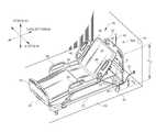
- FIG. 1is a perspective view of a bed of the type used in a health care facility showing occupant presence detectors associated with the bed for detecting occupant presence or absence.
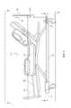
- FIG. 2is a schematic side elevation view of a bed of the type used in a health care facility showing occupant presence detectors for detecting occupant presence or absence along corresponding surveillance planes.
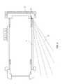
- FIGS. 3 and 4are views taken in the directions 3 - 3 and 4 - 4 respectively of FIG. 2 .
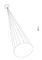
- FIG. 5is schematic view of a presence detector for detecting presence or absence in a three dimensional region.
- FIGS. 6 and 7are plan views each showing arrays of presence detectors for detecting presence or absence along a surveillance plane.
- FIG. 8is a table summarizing bed occupant condition assessments corresponding to various combinations of states indicated by two occupant presence detectors and an occupancy detector.
- FIG. 9is a table summarizing bed occupant condition assessments corresponding to various combinations of states indicated by three occupant presence detectors and an occupancy detector.
- FIGS. 10 and 11are timelines showing time delays ⁇ t 1 and ⁇ t 2 that may be useful in making occupant condition assessments.
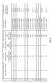
- FIG. 12is a table summarizing bed occupant condition assessments based in part on a temporal relationship between changes in state indications of three presence detectors when the occupant is not occupying the bed.
- FIG. 1shows an occupant support exemplified by hospital bed 20 having a base frame 22 and an elevatable frame 24 which is elevation adjustable relative to the base frame.
- the bedalso includes a mattress 26 having a torso section 28 and a leg section 30 . At least the torso section of the mattress rests on a deck section which is rotatably secured to the elevatable frame so that the deck section, and therefore the torso mattress section, can be rotated through a desired orientation angle ⁇ .
- a headboard 36is secured to the base frame at the head end of the bed; a footboard 38 is secured to the elevatable frame at the foot end of the bed.
- Four siderails 40are secured to the elevatable frame. The siderails can be raised or lowered.
- Casters 44extend from the base frame to floor 50 .
- a communication line 52extends from the bed to a wall jack to convey information from the bed to remote destinations such as a nurses' station.
- the illustrationalso shows lateral, longitudinal and vertical directional
- the bedalso includes a scale for measuring the weight of the bed occupant.
- a typical scalecomprises load cells (not shown) and related hardware and circuits to determine whether or not occupant weight is being borne by the occupant support.
- the bedmay also include an occupant or patient position monitoring (PPM) system to monitor the position of the bed occupant.
- PPMpatient position monitoring
- a typical PPM systemuses the electrical output of the load cells to determine occupant position on the bed.
- the bedmay use switches or sensors that do not measure weight to determine whether or not the occupant support is bearing the weight of an occupant.
- Associated softwarecan be used to alert the hospital staff if the occupant is in a position consistent with an attempt to exit the bed, or if the occupant has actually exited the bed. Such alerts are useful for monitoring occupants who are not authorized to exit the bed without assistance.
- Some bed occupantsare healthy enough to exit the bed without the assistance of an attendant, and are authorized to do so. An occupant might exit the bed to use a nearby washroom. Although the occupant is authorized to exit the bed without assistance, it is recognized that the occupant may nevertheless be more susceptible to an adverse post-exit event, such as a fall, than a healthier person. If the occupant is not authorized to exit the bed without assistance, he or she may nevertheless make an unauthorized exit that escapes detection. Either way, it is desirable to assess whether the post-exit condition of the occupant is satisfactory (e.g. has not fallen) or unsatisfactory (e.g. has fallen).
- occupantrefers to the intended or assigned occupant of the occupant support whether or not that occupant is actually occupying the occupant support at any given time.
- the bed 20is augmented with a detection system for assessing the condition of the occupant, especially the condition of an occupant who has exited the bed.
- the detection systemincludes first and second presence detectors 58 , 62 for detecting the presence of a “target”, specifically the occupant, at least after the occupant has exited the bed.
- First detector 58is a “high” detector mounted on the headboard no higher than a prescribed height h H relative to floor 50 .
- Prescribed height h His a height low enough that 99% of the members of a population sample would be at least as tall as height h H when standing on floor 50 and 1% of the population sample would be shorter than h H . In other words the shortest person in the 99% group would be h H tall.
- the high detectorcould be mounted on a nearby wall 54 (as shown by detector 58 A) provided its status as a component of the detection system for the specific bed 20 of interest is recognized.
- An additional optionis to make the detector height adjustable by mounting it on, for example, a telescoping mast such as mast 48 projecting from the headboard.
- FIG. 1shows the first detector laterally centered on the bed, however the detector could also be laterally offset from the lateral center of the bed, in which case a practical commercial embodiment would likely have a companion detector laterally offset in the opposite direction.
- FIG. 1shows the second detector on only the left side of the bed, however a practical commercial embodiment would be expected to have a companion detector on the right side of the bed.
- detectorscan be placed not just at the head end of the bed but at the foot end and/or at other locations.
- Second detector 62is a “low” detector spaced from the first detector by a difference in elevation.
- the low detectoris mounted on the bed base frame 22 no higher than a specified height h L relative to floor 50 .
- Specified height h Lis about 25 centimeters above floor level.
- the low detectorcould be mounted on a nearby wall 54 provided its status as a component of the detection system for the specific bed 20 of interest is recognized.
- Presence detectorIf the intended target of a presence detector is not present, the detector will perceive an absence of the target. Accordingly, the presence detector may be thought of as a “presence or absence detector”. In the interest of simplicity, this specification will frequently use the phrase “presence detector” as an abbreviated way to refer to a “presence or absence detector” and will frequently use the phrase “detecting presence” as an abbreviated way to refer to “detecting presence or absence. Other phrases using “presence” or variations thereof similarly refer to the alternative, mutually exclusive state of absence.
- FIGS. 2-4show various possible arrangements of the presence detectors and the spatial regions they monitor.
- FIG. 2shows both the high and low detectors 58 , 62 mounted on the bed. Each detector is arranged to detect occupant presence in different, substantially planar surveillance regions, a higher elevation surveillance plane 68 , and a lower elevation surveillance plane 72 .
- the coverage pattern of the detectorsmay be adapted to the specific requirements and constraints of the bed and the local environment.
- FIGS. 2 and 3show the high detector having a planar coverage region that fans out laterally with increasing distance away from the detector.
- FIGS. 3 and 4show the low detector having a similar planar fan pattern, part of which has been masked to suppress coverage in region S. These two patterns are merely examples of coverage patterns that may be useful.
- the fan patternis better suited for the high detector and the masked fan pattern better suited for the low detector.
- three dimensional coverage patternssuch as the conical pattern of FIG. 5 may be useful.
- FIG. 1shows a single high detector 58 and a single low detector 62 , however each detector can be in the form of a detector array.
- FIG. 6shows one example array comprising three laterally distributed detectors, 58 a , 58 b , 58 c , the medial one of which, 58 b , is longitudinally offset from the other two to cover a region T that would otherwise not be monitored.
- FIG. 7shows a detector array in which two laterally spaced apart detectors 58 d , 58 e are oriented, aimed or masked so that the meanlines 76 , 78 of their coverage patterns are oblique to the longitudinal direction to cover a region V that would otherwise not be monitored.
- the detection systemalso includes an occupancy detector for determining if the occupant is actually occupying the occupant support.
- the scaleitself may conveniently serve as an occupancy detector. That is, a scale reading substantially less than the occupant's weight, which is usually accurately known, can be interpreted as an indication of non-occupancy whereas a higher reading, especially a reading consistent with the occupant's weight, can interpreted as an indication of occupancy.
- a PPM system outputindicating that the occupant has left the bed can serve as an occupancy/non-occupancy detector.
- the occupancy indicationcould be based on rate of change of weight.
- the presence detectors 58 , 62monitor for occupant presence in the corresponding two surveillance planes 68 , 72 .
- the occupancy detectordetermines if the occupant is actually occupying the bed.
- the presence detection systememploys a processor or other analyzer to assess the condition of the occupant based on the indications from the presence detectors and the occupancy detector.
- Example condition assessment rulesare summarized in the table of FIG. 8 in which “P” signifies that a presence detector perceives a state of occupant presence and “A” signifies that a presence detector indicates a state of occupant absence.
- the condition assessmentis “Satisfactory” irrespective of whether the low and high presence detectors detect a state of occupant presence or a state of occupant absence at their respective surveillance planes 68 , 72 .
- the system designermay prefer to assign a “Null” value to the condition assessments in which the occupant is occupying the bed.
- the systemrecognizes that the occupant is at risk of a detectable adverse event, such as a fall. If both the high and low detectors perceive a state of occupant presence (row 5) the system makes an assessment of “Satisfactory”. If the high detector perceives a state of occupant absence and the low detector perceives a state of occupant presence (row 7) it is plausible to conclude that the occupant has fallen. Accordingly, the system makes a condition assessment of “Unsatisfactory”.
- the systemmakes a condition assessment of “Satisfactory” because the states of presence and absence are not consistent with a fallen occupant.
- a system “Fault” assessmentmay be substituted for the occupant condition assessment.
- both the high detector and the low detectorperceive a state of occupant absence (row 8) the system makes a condition assessment of “Satisfactory” because the states of presence and absence are not consistent with a fallen occupant.
- the state of absence indicated by the high detectormay be sufficient cause to assess that the occupant's condition is “Unsatisfactory”, or, given the implausibility of the presence detection states tabulated in row 8, a system “Fault” assessment may be substituted for the occupant condition assessment.
- the combination of states in row 8may also be interpreted as signifying that the occupant has moved out of range of the presence detectors.
- the system designermay exercise some latitude in determining the interpretation to assign to various combinations of the states indicated by the presence and occupancy detectors.
- the systemIn response to an occupant condition assessment of “unsatisfactory”, the system issues an alarm or activates an alarm.
- the systemmay use the communication line 52 ( FIG. 1 ) to convey a signal which activates an alarm at a nurses' station.
- a variant of the above described bed and detection systemincludes an intermediate detector 60 at an elevation vertically between the high and low detectors.
- the intermediate detectormonitors for occupant presence along a substantially planar surveillance region, specifically at surveillance plane 70 .
- Example condition assessment rules for this tri-level systemare summarized in the table of FIG. 9 in which “P” signifies that a presence detector perceives a state of occupant presence and “A” signifies that a presence detector indicates a state of occupant absence.
- the condition assessmentis “Satisfactory” irrespective of whether the low, intermediate and high presence detectors detect a state of occupant presence or a state of occupant absence at their respective surveillance planes 68 , 70 , 72 .
- the system designermay prefer to assign a “Null” value to the condition assessments in which the occupant is occupying the bed.
- the systemWhen the occupant is perceived as not being on the bed (rows 9-16 of the table) the system recognizes that the occupant is at risk of a detectable adverse event, such as a fall. If all three detectors perceive a state of occupant presence (row 9) the system makes an assessment of “Satisfactory”. If the high detector perceives a state of occupant absence and both the intermediate and low detectors perceive a state of occupant presence (row 13) or if the high and intermediate detectors perceive a state of occupant absence and the low detector perceives a state of occupant presence (row 15) it is plausible to conclude that the occupant has fallen. Accordingly, the system makes a condition assessment of “Unsatisfactory”.
- the state combinations shown in rows 10, 11, 12 and 14cause the system to make a condition assessment of “Satisfactory” because the states of presence and absence are not consistent with a fallen occupant.
- a system “Fault” assessmentmay be substituted for the occupant condition assessment. If all three detectors perceive a state of occupant absence (row 16) the system makes a condition assessment of “Satisfactory” because the states of presence and absence are not consistent with a fallen occupant.
- a system “Fault” assessmentmay be substituted for the occupant condition assessment.
- the combination of states in row 16may also be interpreted as signifying that the occupant has moved out of range of the presence detectors.
- t 0is the time at which the occupant has exited the bed as determined by the occupancy detector.
- the indication of non-occupancyis taken into account, at least in the context of fall detection, only if it persists for a time interval ⁇ t 1 that exceeds a minimum value. This initial time delay may be desirable to account for time necessary for the occupant to move into “view” of the presence detectors.
- the presence detectorsAfter expiration of time interval ⁇ t 1 the presence detectors sample (or continue to sample) their surveillance regions at sampling intervals of ⁇ t s and, at each subsequent time t 1 , t 2 , t 3 , etc., indicate a state of occupant presence P or occupant absence A. If occupant absence is indicated, as is the case at time t 5 in FIG. 10 , the presence detector continues to sample for occupant presence. The system compares the indication at time t 5 to the indication obtained at a later time t 10 , which is a timeout interval of ⁇ t 2 later than t 5 . The occupant is considered to be absent only if, as seen in FIG.
- the indication at t 5is “absent” and the indication at t 10 , is also “absent”. However if the indication at t 5 is “absent” and the indication at t 10 is “present” as seen in FIG. 11 , the occupant is considered to be present.
- a time interval ⁇ t 1 of up to about five secondsis thought to be satisfactory.
- a timeout interval ⁇ t 2 of between about 0.2 and 2.0 secondsis thought to be satisfactory.
- the presence detectors 58 , 60 , 62may be motion detectors for detecting motion of the occupant or absence of such motion.
- suitable motion detectorsinclude those based on ultrasonic, low power radar and infrared technologies. It is nevertheless emphasized that presence detection technologies other than motion sensing technologies may also be useful. If the system designer employs motion sensors, the indications of presence and absence can be based on characteristics of the motion, such as intensity and frequency, and the differences or similarities in those motion characteristics from one surveillance region to another.
- the presence detectorsindicate a state of presence or absence in their respective regions of surveillance and the condition assessment depends on a temporal relationship between changes in the state indicated by detectors monitoring different spatial regions.
- a system using only two detectorssuch as first and second detectors 58 , 62 , could make a condition assessment based on a temporal relationship between a change in the state indication of the first detector and a change in the state indication of the second detector.
- the unsatisfactory conditioncorresponds to the state indication of one of the detectors changing from “present” to “absent” prior to or without a subsequent change in the state indication of the other detector from “present” to “absent”.
- the one detectorwould be the relatively higher elevation detector and the other detector would be the relatively lower elevation detector.
- the use of a temporal relationship to make the condition assessmentcan also be extended to systems that monitor for occupant presence in more than two spatial regions.
- the table of FIG. 12summarizes example rules for a three-detector system (e.g. detectors 58 , 60 , 62 ) when the occupancy detector indicates that the occupant is not occupying the bed.
- Row 1 of the tablecorresponds to an event sequence in which the state indication of the high detector changes from “present” to “absent” with no change in the states of the intermediate and low detectors.
- Row 4corresponds to an event sequence in which the state indication of the high detector changes from “present” to “absent” followed by a change in the state indication of the intermediate detector from “present” to “absent” with no change in the state of the low detector.
- Row 10corresponds to an event sequence in which the state indication of the high detector changes from “present” to “absent” followed by a change in the state indication of the intermediate detector from “present” to “absent” followed by a change in the state indication of the low detector from “present” to “absent”.
- the change in state indicationis spatially and temporally consistent with a fall event, therefore the condition assessment is “unsatisfactory”.
- Row 2corresponds to an event sequence in which the state indication of the intermediate detector changes from “present” to “absent” with no change in the states of the high and low detectors.
- Row 3corresponds to an event sequence in which the state indication of the low detector changes from “present” to “absent” with no change in the states of the high and intermediate detectors.
- Row 6corresponds to an event sequence in which the state indication of the intermediate detector changes from “present” to “absent” followed by a change in the state indication of the high detector from “present” to “absent” with no change in the state indication of the low detector.
- the end statelow detector indicating present while the high and intermediate detectors indicate “absent” is consistent with an occupant fall event. Accordingly, the system makes a condition assessment of “unsatisfactory”.
- Rows 5, 7, 8 and 9correspond to event sequences in which the end state (occupant presence detected in a plane other than the low plane 72 but not in the remaining two planes) has been judged to be inconsistent with a fall. Accordingly, the system issues a condition assessment of “satisfactory”, even though the relative temporal order of two of the event sequences (rows 5 and 7) is not inconsistent with a fall.
- Rows 11-15correspond to event sequences in which the temporal order of the state changes can be interpreted as being inconsistent with a fall event.
- the sequence of row 11is somewhat consistent with a fall event insofar as the high detector was the first to indicate a change from “present” to “absent”. Accordingly, the sequence of row 11 results in a condition assessment of “unsatisfactory” whereas the event sequences of rows 12 through 15 each result in an assessment of a system fault condition rather than an assessment of the occupant's condition.
- the presence detectorsare employed after the occupant has left the bed, it may be desirable to power them only after the scale or PPM system indicates that the occupant is no longer occupying the bed or is in a position compatible with an intention to exit the bed.
- presence detectorshaving adjustable sensitivity and/or range so that caregivers can adjust these parameters depending on the fall susceptibility of the occupant and the local environment.
Landscapes
- Health & Medical Sciences (AREA)
- Life Sciences & Earth Sciences (AREA)
- Veterinary Medicine (AREA)
- Animal Behavior & Ethology (AREA)
- General Health & Medical Sciences (AREA)
- Public Health (AREA)
- Physics & Mathematics (AREA)
- Medical Informatics (AREA)
- Dentistry (AREA)
- Oral & Maxillofacial Surgery (AREA)
- Surgery (AREA)
- Biophysics (AREA)
- Pathology (AREA)
- Engineering & Computer Science (AREA)
- Biomedical Technology (AREA)
- Heart & Thoracic Surgery (AREA)
- Physiology (AREA)
- Molecular Biology (AREA)
- Nursing (AREA)
- Alarm Systems (AREA)
- Air Bags (AREA)
Abstract
Description
Claims (48)
Priority Applications (2)
| Application Number | Priority Date | Filing Date | Title |
|---|---|---|---|
| US12/751,258US8350709B2 (en) | 2010-03-31 | 2010-03-31 | Presence detector and occupant support employing the same |
| EP11159839.7AEP2371336A3 (en) | 2010-03-31 | 2011-03-25 | Presence detector and occupant support employing the same |
Applications Claiming Priority (1)
| Application Number | Priority Date | Filing Date | Title |
|---|---|---|---|
| US12/751,258US8350709B2 (en) | 2010-03-31 | 2010-03-31 | Presence detector and occupant support employing the same |
Publications (2)
| Publication Number | Publication Date |
|---|---|
| US20110241886A1 US20110241886A1 (en) | 2011-10-06 |
| US8350709B2true US8350709B2 (en) | 2013-01-08 |
Family
ID=44260434
Family Applications (1)
| Application Number | Title | Priority Date | Filing Date |
|---|---|---|---|
| US12/751,258Active2031-05-07US8350709B2 (en) | 2010-03-31 | 2010-03-31 | Presence detector and occupant support employing the same |
Country Status (2)
| Country | Link |
|---|---|
| US (1) | US8350709B2 (en) |
| EP (1) | EP2371336A3 (en) |
Cited By (21)
| Publication number | Priority date | Publication date | Assignee | Title |
|---|---|---|---|---|
| US20140059768A1 (en)* | 2005-11-07 | 2014-03-06 | Stryker Corporation | Hospital bed |
| US9370457B2 (en) | 2013-03-14 | 2016-06-21 | Select Comfort Corporation | Inflatable air mattress snoring detection and response |
| US9392879B2 (en) | 2013-03-14 | 2016-07-19 | Select Comfort Corporation | Inflatable air mattress system architecture |
| US9445751B2 (en) | 2013-07-18 | 2016-09-20 | Sleepiq Labs, Inc. | Device and method of monitoring a position and predicting an exit of a subject on or from a substrate |
| US9504416B2 (en) | 2013-07-03 | 2016-11-29 | Sleepiq Labs Inc. | Smart seat monitoring system |
| US9510688B2 (en) | 2013-03-14 | 2016-12-06 | Select Comfort Corporation | Inflatable air mattress system with detection techniques |
| US9635953B2 (en) | 2013-03-14 | 2017-05-02 | Sleepiq Labs Inc. | Inflatable air mattress autofill and off bed pressure adjustment |
| US9770114B2 (en) | 2013-12-30 | 2017-09-26 | Select Comfort Corporation | Inflatable air mattress with integrated control |
| US9814410B2 (en) | 2014-05-06 | 2017-11-14 | Stryker Corporation | Person support apparatus with position monitoring |
| US9844275B2 (en) | 2013-03-14 | 2017-12-19 | Select Comfort Corporation | Inflatable air mattress with light and voice controls |
| US10058467B2 (en) | 2013-03-14 | 2018-08-28 | Sleep Number Corporation | Partner snore feature for adjustable bed foundation |
| US10092242B2 (en) | 2015-01-05 | 2018-10-09 | Sleep Number Corporation | Bed with user occupancy tracking |
| US10149549B2 (en) | 2015-08-06 | 2018-12-11 | Sleep Number Corporation | Diagnostics of bed and bedroom environment |
| US10182661B2 (en) | 2013-03-14 | 2019-01-22 | Sleep Number Corporation and Select Comfort Retail Corporation | Inflatable air mattress alert and monitoring system |
| US10448749B2 (en) | 2014-10-10 | 2019-10-22 | Sleep Number Corporation | Bed having logic controller |
| US10674832B2 (en) | 2013-12-30 | 2020-06-09 | Sleep Number Corporation | Inflatable air mattress with integrated control |
| US11020055B1 (en) | 2020-06-19 | 2021-06-01 | Edward Li | Intelligent multifunction bed monitor |
| US11439345B2 (en) | 2006-09-22 | 2022-09-13 | Sleep Number Corporation | Method and apparatus for monitoring vital signs remotely |
| US11737938B2 (en) | 2017-12-28 | 2023-08-29 | Sleep Number Corporation | Snore sensing bed |
| US12097154B2 (en) | 2021-02-26 | 2024-09-24 | Hill-Rom Services, Inc. | Universal load cell features that characterize patient motion in three dimensions in a hospital bed |
| US12390379B2 (en) | 2017-12-28 | 2025-08-19 | Sleep Number Corporation | Bed having snore detection feature |
Families Citing this family (7)
| Publication number | Priority date | Publication date | Assignee | Title |
|---|---|---|---|---|
| US20170155877A1 (en)* | 2008-05-06 | 2017-06-01 | Careview Communications, Inc. | System and method for predicting patient falls |
| JP2016030180A (en)* | 2014-07-30 | 2016-03-07 | 船井電機株式会社 | Watching device |
| US11763935B2 (en)* | 2020-01-06 | 2023-09-19 | National Cheng Kung University | Care system for predicting bed exit and patient management system including the same |
| EP4014862A1 (en)* | 2020-12-18 | 2022-06-22 | nevisQ GmbH | Method, monitoring device and monitoring system for detecting an entry of a person into a bed and / or a person getting out of the bed |
| US11804121B2 (en)* | 2021-04-01 | 2023-10-31 | Lenovo (Singapore) Pte. Ltd. | Human presence detector device |
| GB202108554D0 (en)* | 2021-06-16 | 2021-07-28 | Essence Smartcare Ltd | Occupancy dependent fall detection |
| US12144608B2 (en) | 2021-06-22 | 2024-11-19 | Hill-Rom Services, Inc. | Three-mode patient chair exit sensing |
Citations (7)
| Publication number | Priority date | Publication date | Assignee | Title |
|---|---|---|---|---|
| US6049281A (en) | 1998-09-29 | 2000-04-11 | Osterweil; Josef | Method and apparatus for monitoring movements of an individual |
| US6166644A (en)* | 1998-09-10 | 2000-12-26 | Senior Technologies, Inc. | Patient monitoring system |
| US20060264785A1 (en)* | 2005-05-19 | 2006-11-23 | Barton Dring | Monitoring systems and methods |
| US20080221466A1 (en)* | 2005-04-20 | 2008-09-11 | Koninklijke Philips Electronics N. V. | Patient Monitoring System |
| US7472437B2 (en)* | 2002-04-19 | 2009-01-06 | Hill-Rom Services, Inc. | Hospital bed obstacle detection device and method |
| US20090121881A1 (en)* | 2002-11-21 | 2009-05-14 | Anders Fredriksson | Method and device for fall prevention and detection |
| US20120140068A1 (en)* | 2005-05-06 | 2012-06-07 | E-Watch, Inc. | Medical Situational Awareness System |
Family Cites Families (4)
| Publication number | Priority date | Publication date | Assignee | Title |
|---|---|---|---|---|
| JP3389376B2 (en)* | 1995-08-31 | 2003-03-24 | セイコープレシジョン株式会社 | Bed human body detection device |
| JP3420079B2 (en)* | 1998-09-29 | 2003-06-23 | 松下電器産業株式会社 | Condition detection system |
| JP2001327549A (en)* | 2000-05-22 | 2001-11-27 | Anima Kk | Moving state detecting system and moving state detector |
| JP4650352B2 (en)* | 2006-06-26 | 2011-03-16 | パナソニック電工株式会社 | Sleep state evaluation system |
- 2010
- 2010-03-31USUS12/751,258patent/US8350709B2/enactiveActive
- 2011
- 2011-03-25EPEP11159839.7Apatent/EP2371336A3/ennot_activeWithdrawn
Patent Citations (7)
| Publication number | Priority date | Publication date | Assignee | Title |
|---|---|---|---|---|
| US6166644A (en)* | 1998-09-10 | 2000-12-26 | Senior Technologies, Inc. | Patient monitoring system |
| US6049281A (en) | 1998-09-29 | 2000-04-11 | Osterweil; Josef | Method and apparatus for monitoring movements of an individual |
| US7472437B2 (en)* | 2002-04-19 | 2009-01-06 | Hill-Rom Services, Inc. | Hospital bed obstacle detection device and method |
| US20090121881A1 (en)* | 2002-11-21 | 2009-05-14 | Anders Fredriksson | Method and device for fall prevention and detection |
| US20080221466A1 (en)* | 2005-04-20 | 2008-09-11 | Koninklijke Philips Electronics N. V. | Patient Monitoring System |
| US20120140068A1 (en)* | 2005-05-06 | 2012-06-07 | E-Watch, Inc. | Medical Situational Awareness System |
| US20060264785A1 (en)* | 2005-05-19 | 2006-11-23 | Barton Dring | Monitoring systems and methods |
Cited By (54)
| Publication number | Priority date | Publication date | Assignee | Title |
|---|---|---|---|---|
| US9539156B2 (en)* | 2005-11-07 | 2017-01-10 | Stryker Corporation | Hospital bed |
| US20140059768A1 (en)* | 2005-11-07 | 2014-03-06 | Stryker Corporation | Hospital bed |
| US11439345B2 (en) | 2006-09-22 | 2022-09-13 | Sleep Number Corporation | Method and apparatus for monitoring vital signs remotely |
| US11096849B2 (en) | 2013-03-14 | 2021-08-24 | Sleep Number Corporation | Partner snore feature for adjustable bed foundation |
| US11122909B2 (en) | 2013-03-14 | 2021-09-21 | Sleep Number Corporation | Inflatable air mattress system with detection techniques |
| US9510688B2 (en) | 2013-03-14 | 2016-12-06 | Select Comfort Corporation | Inflatable air mattress system with detection techniques |
| US11957250B2 (en) | 2013-03-14 | 2024-04-16 | Sleep Number Corporation | Bed system having central controller using pressure data |
| US9635953B2 (en) | 2013-03-14 | 2017-05-02 | Sleepiq Labs Inc. | Inflatable air mattress autofill and off bed pressure adjustment |
| US12185839B2 (en) | 2013-03-14 | 2025-01-07 | Sleep Number Corporation | Mattress controller with alert system |
| US11766136B2 (en) | 2013-03-14 | 2023-09-26 | Sleep Number Corporation | Inflatable air mattress alert and monitoring system |
| US9844275B2 (en) | 2013-03-14 | 2017-12-19 | Select Comfort Corporation | Inflatable air mattress with light and voice controls |
| US12193576B2 (en) | 2013-03-14 | 2025-01-14 | Sleep Number Corporation | Mattress control system |
| US10058467B2 (en) | 2013-03-14 | 2018-08-28 | Sleep Number Corporation | Partner snore feature for adjustable bed foundation |
| US9392879B2 (en) | 2013-03-14 | 2016-07-19 | Select Comfort Corporation | Inflatable air mattress system architecture |
| US11712384B2 (en) | 2013-03-14 | 2023-08-01 | Sleep Number Corporation | Partner snore feature for adjustable bed foundation |
| US10182661B2 (en) | 2013-03-14 | 2019-01-22 | Sleep Number Corporation and Select Comfort Retail Corporation | Inflatable air mattress alert and monitoring system |
| US10201234B2 (en) | 2013-03-14 | 2019-02-12 | Sleep Number Corporation | Inflatable air mattress system architecture |
| US10632032B1 (en) | 2013-03-14 | 2020-04-28 | Sleep Number Corporation | Partner snore feature for adjustable bed foundation |
| US10251490B2 (en) | 2013-03-14 | 2019-04-09 | Sleep Number Corporation | Inflatable air mattress autofill and off bed pressure adjustment |
| US10441086B2 (en) | 2013-03-14 | 2019-10-15 | Sleep Number Corporation | Inflatable air mattress system with detection techniques |
| US11497321B2 (en) | 2013-03-14 | 2022-11-15 | Sleep Number Corporation | Inflatable air mattress system architecture |
| US9370457B2 (en) | 2013-03-14 | 2016-06-21 | Select Comfort Corporation | Inflatable air mattress snoring detection and response |
| US11160683B2 (en) | 2013-03-14 | 2021-11-02 | Sleep Number Corporation | Inflatable air mattress snoring detection and response and related methods |
| US10980351B2 (en) | 2013-03-14 | 2021-04-20 | Sleep Number Corporation et al. | Inflatable air mattress autofill and off bed pressure adjustment |
| US10492969B2 (en) | 2013-03-14 | 2019-12-03 | Sleep Number Corporation | Partner snore feature for adjustable bed foundation |
| US12274369B2 (en) | 2013-03-14 | 2025-04-15 | Sleep Number Corporation | Bed system with star topology pump controller |
| US12233009B2 (en) | 2013-03-14 | 2025-02-25 | Sleep Number Corporation | Controlling device for adjustable bed foundation |
| US10881219B2 (en) | 2013-03-14 | 2021-01-05 | Sleep Number Corporation | Inflatable air mattress system architecture |
| US10646050B2 (en) | 2013-03-14 | 2020-05-12 | Sleep Number Corporation et al. | Inflatable air mattress alert and monitoring system |
| US12226021B2 (en) | 2013-03-14 | 2025-02-18 | Sleep Number Corporation | Inflatable air mattress autofill and off bed pressure adjustment |
| US12029323B2 (en) | 2013-03-14 | 2024-07-09 | Sleep Number Corporation | Bed system having mattress and wake-up control system |
| US9504416B2 (en) | 2013-07-03 | 2016-11-29 | Sleepiq Labs Inc. | Smart seat monitoring system |
| US9931085B2 (en) | 2013-07-18 | 2018-04-03 | Select Comfort Retail Corporation | Device and method of monitoring a position and predicting an exit of a subject on or from a substrate |
| US9445751B2 (en) | 2013-07-18 | 2016-09-20 | Sleepiq Labs, Inc. | Device and method of monitoring a position and predicting an exit of a subject on or from a substrate |
| US10674832B2 (en) | 2013-12-30 | 2020-06-09 | Sleep Number Corporation | Inflatable air mattress with integrated control |
| US11744384B2 (en) | 2013-12-30 | 2023-09-05 | Sleep Number Corporation | Inflatable air mattress with integrated control |
| US9770114B2 (en) | 2013-12-30 | 2017-09-26 | Select Comfort Corporation | Inflatable air mattress with integrated control |
| US10231647B2 (en) | 2014-05-06 | 2019-03-19 | Stryker Corporation | Person support apparatus with position monitoring |
| US9814410B2 (en) | 2014-05-06 | 2017-11-14 | Stryker Corporation | Person support apparatus with position monitoring |
| US11206929B2 (en) | 2014-10-10 | 2021-12-28 | Sleep Number Corporation | Bed having logic controller |
| US10448749B2 (en) | 2014-10-10 | 2019-10-22 | Sleep Number Corporation | Bed having logic controller |
| US12364342B2 (en) | 2014-10-10 | 2025-07-22 | Sleep Number Corporation | Bed system having controller for an air mattress |
| US11896139B2 (en) | 2014-10-10 | 2024-02-13 | Sleep Number Corporation | Bed system having controller for an air mattress |
| US10092242B2 (en) | 2015-01-05 | 2018-10-09 | Sleep Number Corporation | Bed with user occupancy tracking |
| US12167921B2 (en) | 2015-01-05 | 2024-12-17 | Sleep Number Corporation | Bed with user weight tracking |
| US10716512B2 (en) | 2015-01-05 | 2020-07-21 | Sleep Number Corporation | Bed with user occupancy tracking |
| US11849853B2 (en) | 2015-08-06 | 2023-12-26 | Sleep Number Corporation | Diagnostics of bed and bedroom environment |
| US10729255B2 (en) | 2015-08-06 | 2020-08-04 | Sleep Number Corporation | Diagnostics of bed and bedroom environment |
| US10149549B2 (en) | 2015-08-06 | 2018-12-11 | Sleep Number Corporation | Diagnostics of bed and bedroom environment |
| US12376686B2 (en) | 2015-08-06 | 2025-08-05 | Sleep Number Corporation | Diagnostics of bed and bedroom environment |
| US11737938B2 (en) | 2017-12-28 | 2023-08-29 | Sleep Number Corporation | Snore sensing bed |
| US12390379B2 (en) | 2017-12-28 | 2025-08-19 | Sleep Number Corporation | Bed having snore detection feature |
| US11020055B1 (en) | 2020-06-19 | 2021-06-01 | Edward Li | Intelligent multifunction bed monitor |
| US12097154B2 (en) | 2021-02-26 | 2024-09-24 | Hill-Rom Services, Inc. | Universal load cell features that characterize patient motion in three dimensions in a hospital bed |
Also Published As
| Publication number | Publication date |
|---|---|
| EP2371336A2 (en) | 2011-10-05 |
| EP2371336A3 (en) | 2013-05-15 |
| US20110241886A1 (en) | 2011-10-06 |
Similar Documents
| Publication | Publication Date | Title |
|---|---|---|
| US8350709B2 (en) | Presence detector and occupant support employing the same | |
| US12268642B2 (en) | Person support apparatuses with exit detection systems | |
| US12144607B2 (en) | Exit detection system with compensation | |
| US10478359B2 (en) | Person support apparatuses with acceleration detection | |
| US8620625B2 (en) | Above bed sensor | |
| US8866620B2 (en) | System and method for fall prevention and detection | |
| US6822571B2 (en) | Patient movement detection system for a bed including a load cell mounting assembly | |
| KR101043864B1 (en) | Bed system with bed deviation prediction and detection system | |
| EP2995242B1 (en) | Patient support apparatus | |
| JP4128728B2 (en) | Bed equipment | |
| JP4841462B2 (en) | Bed equipment | |
| JP2020502701A (en) | System for predicting exit from user support | |
| JP2021103486A (en) | Target person state detection device and target person state detection method | |
| US20220084383A1 (en) | System and method for monitoring an individual using lidar | |
| US20210068710A1 (en) | System and process for monitoring a position stability | |
| JP5204263B2 (en) | Bed presence detection method and bed presence detection device | |
| KR20240084207A (en) | Patient state analysis apparatus | |
| JP2000241561A (en) | Bed state detection device and method | |
| JP5774152B2 (en) | How to detect bed condition | |
| JP4832891B2 (en) | Bed presence detection method | |
| CN105520753B (en) | A kind of monitoring method based on ultrasound | |
| JP5406334B2 (en) | Bed presence detection method and bed presence detection device | |
| JP2024043475A (en) | Abnormality determination system | |
| JP2012161681A (en) | Bed occupancy state detection method | |
| WO2011026448A1 (en) | A method and device for evaluation of the risk of decubitus development in a patient in a hospital bed |
Legal Events
| Date | Code | Title | Description |
|---|---|---|---|
| AS | Assignment | Owner name:HILL-ROM SERVICES, INC., DELAWARE Free format text:ASSIGNMENT OF ASSIGNORS INTEREST;ASSIGNOR:RECEVEUR, TIMOTHY JOSEPH;REEL/FRAME:024168/0152 Effective date:20100331 | |
| AS | Assignment | Owner name:HILL-ROM SERVICES, INC., INDIANA Free format text:CHANGE OF STATE OF INCORPORATION FROM DELAWARE TO INDIANA;ASSIGNOR:HILL-ROM SERVICES, INC. (DELAWARE CORPORATION;REEL/FRAME:029414/0480 Effective date:20101231 | |
| STCF | Information on status: patent grant | Free format text:PATENTED CASE | |
| AS | Assignment | Owner name:JPMORGAN CHASE BANK, N.A., AS COLLATERAL AGENT, ILLINOIS Free format text:SECURITY INTEREST;ASSIGNORS:ALLEN MEDICAL SYSTEMS, INC.;HILL-ROM SERVICES, INC.;ASPEN SURGICAL PRODUCTS, INC.;AND OTHERS;REEL/FRAME:036582/0123 Effective date:20150908 Owner name:JPMORGAN CHASE BANK, N.A., AS COLLATERAL AGENT, IL Free format text:SECURITY INTEREST;ASSIGNORS:ALLEN MEDICAL SYSTEMS, INC.;HILL-ROM SERVICES, INC.;ASPEN SURGICAL PRODUCTS, INC.;AND OTHERS;REEL/FRAME:036582/0123 Effective date:20150908 | |
| FPAY | Fee payment | Year of fee payment:4 | |
| AS | Assignment | Owner name:JPMORGAN CHASE BANK, N.A., AS COLLATERAL AGENT, ILLINOIS Free format text:SECURITY AGREEMENT;ASSIGNORS:HILL-ROM SERVICES, INC.;ASPEN SURGICAL PRODUCTS, INC.;ALLEN MEDICAL SYSTEMS, INC.;AND OTHERS;REEL/FRAME:040145/0445 Effective date:20160921 Owner name:JPMORGAN CHASE BANK, N.A., AS COLLATERAL AGENT, IL Free format text:SECURITY AGREEMENT;ASSIGNORS:HILL-ROM SERVICES, INC.;ASPEN SURGICAL PRODUCTS, INC.;ALLEN MEDICAL SYSTEMS, INC.;AND OTHERS;REEL/FRAME:040145/0445 Effective date:20160921 | |
| AS | Assignment | Owner name:MORTARA INSTRUMENT SERVICES, INC., WISCONSIN Free format text:RELEASE BY SECURED PARTY;ASSIGNOR:JPMORGAN CHASE BANK, N.A.;REEL/FRAME:050254/0513 Effective date:20190830 Owner name:WELCH ALLYN, INC., NEW YORK Free format text:RELEASE BY SECURED PARTY;ASSIGNOR:JPMORGAN CHASE BANK, N.A.;REEL/FRAME:050254/0513 Effective date:20190830 Owner name:HILL-ROM, INC., ILLINOIS Free format text:RELEASE BY SECURED PARTY;ASSIGNOR:JPMORGAN CHASE BANK, N.A.;REEL/FRAME:050254/0513 Effective date:20190830 Owner name:VOALTE, INC., FLORIDA Free format text:RELEASE BY SECURED PARTY;ASSIGNOR:JPMORGAN CHASE BANK, N.A.;REEL/FRAME:050254/0513 Effective date:20190830 Owner name:MORTARA INSTRUMENT, INC., WISCONSIN Free format text:RELEASE BY SECURED PARTY;ASSIGNOR:JPMORGAN CHASE BANK, N.A.;REEL/FRAME:050254/0513 Effective date:20190830 Owner name:ANODYNE MEDICAL DEVICE, INC., FLORIDA Free format text:RELEASE BY SECURED PARTY;ASSIGNOR:JPMORGAN CHASE BANK, N.A.;REEL/FRAME:050254/0513 Effective date:20190830 Owner name:HILL-ROM SERVICES, INC., ILLINOIS Free format text:RELEASE BY SECURED PARTY;ASSIGNOR:JPMORGAN CHASE BANK, N.A.;REEL/FRAME:050254/0513 Effective date:20190830 Owner name:HILL-ROM COMPANY, INC., ILLINOIS Free format text:RELEASE BY SECURED PARTY;ASSIGNOR:JPMORGAN CHASE BANK, N.A.;REEL/FRAME:050254/0513 Effective date:20190830 Owner name:ALLEN MEDICAL SYSTEMS, INC., ILLINOIS Free format text:RELEASE BY SECURED PARTY;ASSIGNOR:JPMORGAN CHASE BANK, N.A.;REEL/FRAME:050254/0513 Effective date:20190830 | |
| AS | Assignment | Owner name:JPMORGAN CHASE BANK, N.A., ILLINOIS Free format text:SECURITY AGREEMENT;ASSIGNORS:HILL-ROM HOLDINGS, INC.;HILL-ROM, INC.;HILL-ROM SERVICES, INC.;AND OTHERS;REEL/FRAME:050260/0644 Effective date:20190830 | |
| MAFP | Maintenance fee payment | Free format text:PAYMENT OF MAINTENANCE FEE, 8TH YEAR, LARGE ENTITY (ORIGINAL EVENT CODE: M1552); ENTITY STATUS OF PATENT OWNER: LARGE ENTITY Year of fee payment:8 | |
| AS | Assignment | Owner name:HILL-ROM HOLDINGS, INC., ILLINOIS Free format text:RELEASE OF SECURITY INTEREST AT REEL/FRAME 050260/0644;ASSIGNOR:JPMORGAN CHASE BANK, N.A.;REEL/FRAME:058517/0001 Effective date:20211213 Owner name:BARDY DIAGNOSTICS, INC., ILLINOIS Free format text:RELEASE OF SECURITY INTEREST AT REEL/FRAME 050260/0644;ASSIGNOR:JPMORGAN CHASE BANK, N.A.;REEL/FRAME:058517/0001 Effective date:20211213 Owner name:VOALTE, INC., FLORIDA Free format text:RELEASE OF SECURITY INTEREST AT REEL/FRAME 050260/0644;ASSIGNOR:JPMORGAN CHASE BANK, N.A.;REEL/FRAME:058517/0001 Effective date:20211213 Owner name:HILL-ROM, INC., ILLINOIS Free format text:RELEASE OF SECURITY INTEREST AT REEL/FRAME 050260/0644;ASSIGNOR:JPMORGAN CHASE BANK, N.A.;REEL/FRAME:058517/0001 Effective date:20211213 Owner name:WELCH ALLYN, INC., NEW YORK Free format text:RELEASE OF SECURITY INTEREST AT REEL/FRAME 050260/0644;ASSIGNOR:JPMORGAN CHASE BANK, N.A.;REEL/FRAME:058517/0001 Effective date:20211213 Owner name:ALLEN MEDICAL SYSTEMS, INC., ILLINOIS Free format text:RELEASE OF SECURITY INTEREST AT REEL/FRAME 050260/0644;ASSIGNOR:JPMORGAN CHASE BANK, N.A.;REEL/FRAME:058517/0001 Effective date:20211213 Owner name:HILL-ROM SERVICES, INC., ILLINOIS Free format text:RELEASE OF SECURITY INTEREST AT REEL/FRAME 050260/0644;ASSIGNOR:JPMORGAN CHASE BANK, N.A.;REEL/FRAME:058517/0001 Effective date:20211213 Owner name:BREATHE TECHNOLOGIES, INC., CALIFORNIA Free format text:RELEASE OF SECURITY INTEREST AT REEL/FRAME 050260/0644;ASSIGNOR:JPMORGAN CHASE BANK, N.A.;REEL/FRAME:058517/0001 Effective date:20211213 | |
| MAFP | Maintenance fee payment | Free format text:PAYMENT OF MAINTENANCE FEE, 12TH YEAR, LARGE ENTITY (ORIGINAL EVENT CODE: M1553); ENTITY STATUS OF PATENT OWNER: LARGE ENTITY Year of fee payment:12 |