US8350641B2 - Band selective isolation bridge for splitter - Google Patents
Band selective isolation bridge for splitterDownload PDFInfo
- Publication number
- US8350641B2 US8350641B2US12/693,689US69368910AUS8350641B2US 8350641 B2US8350641 B2US 8350641B2US 69368910 AUS69368910 AUS 69368910AUS 8350641 B2US8350641 B2US 8350641B2
- Authority
- US
- United States
- Prior art keywords
- splitter
- provider
- bandwidth
- pass filter
- coupled
- Prior art date
- Legal status (The legal status is an assumption and is not a legal conclusion. Google has not performed a legal analysis and makes no representation as to the accuracy of the status listed.)
- Active, expires
Links
- 238000002955isolationMethods0.000titleclaimsdescription57
- 241001112258MocaSpecies0.000claims2
- 230000001902propagating effectEffects0.000description25
- 230000002238attenuated effectEffects0.000description21
- 238000011144upstream manufacturingMethods0.000description11
- 238000003780insertionMethods0.000description9
- 230000037431insertionEffects0.000description9
- 239000003990capacitorSubstances0.000description6
- 238000001228spectrumMethods0.000description6
- 238000010586diagramMethods0.000description5
- 238000005516engineering processMethods0.000description5
- 238000004804windingMethods0.000description5
- 230000005540biological transmissionEffects0.000description4
- 230000008901benefitEffects0.000description2
- 238000001816coolingMethods0.000description2
- 238000010438heat treatmentMethods0.000description2
- 238000012986modificationMethods0.000description2
- 230000004048modificationEffects0.000description2
- 230000006855networkingEffects0.000description2
- 230000000644propagated effectEffects0.000description2
- 238000013475authorizationMethods0.000description1
- 230000000903blocking effectEffects0.000description1
- 238000004891communicationMethods0.000description1
- 238000001514detection methodMethods0.000description1
- 238000012544monitoring processMethods0.000description1
- 230000003287optical effectEffects0.000description1
- 230000004044responseEffects0.000description1
- 238000012546transferMethods0.000description1
- 230000007704transitionEffects0.000description1
Images


Classifications
- H—ELECTRICITY
- H04—ELECTRIC COMMUNICATION TECHNIQUE
- H04L—TRANSMISSION OF DIGITAL INFORMATION, e.g. TELEGRAPHIC COMMUNICATION
- H04L12/00—Data switching networks
- H04L12/28—Data switching networks characterised by path configuration, e.g. LAN [Local Area Networks] or WAN [Wide Area Networks]
- H04L12/2803—Home automation networks
- H04L12/2838—Distribution of signals within a home automation network, e.g. involving splitting/multiplexing signals to/from different paths
Definitions
- This disclosurerelates generally to the conveying of information along a transmission path and, more specifically, to a band selective isolation bridge for a splitter.
- electrical signalsconveying information propagate along transmission lines across distances and through splitting devices.
- media contentpropagates downstream from a head-end facility toward media devices located in various facilities such as homes and businesses.
- the electrical signals conveying the media contentpropagate along main trunks, through taps, and along multiple branches that ultimately distribute the content to drop cables at respective facilities.
- the drop cablewhich may be a single coaxial cable, typically is connected to a splitting device having two or more outlet ports. Distribution cables connected to the outlet ports route the signals to various rooms, often extending to one or more media devices.
- the network of distribution cables, splitters, and distribution pointsis referred to as a drop system.
- a typical data distribution networkprovides many content selections to a user's media devices within the drop system, such as one or more televisions equipped with set top boxes or cable modems.
- Content selection propagated on a downstream bandwidth of the CATV systemmay include broadcast television channels, video on demand services, internet data, home security services, and voice over internet (VOIP) services.
- the content selectionsare typically propagated in a discrete frequency range, or channel, that is distinct from the frequency ranges of other content selections.
- Downstream bandwidthincludes frequencies typically ranging from 50-1,000 megahertz (MHz).
- the typical data distribution networkis a two-way communication system.
- the downstream bandwidthcarries signals from the head end to the user and an upstream bandwidth carries upstream signals from the user to the head end.
- Upstream bandwidthmay include data related to video on demand services, such as video requests and billing authorization; internet uploads, such as photo albums or user account information; security monitoring; or other services predicated on signals or data emanating from a subscriber's home.
- Upstream bandwidth frequenciestypically range from 7-49 MHz.
- a user data network, or home networkmay be coupled to the cable television network via the same coaxial cable delivering the downstream and upstream bandwidth of the CATV system.
- the user data networkis a home entertainment network providing multiple streams of high definition video and entertainment. Examples of home networking technologies include Ethernet, HomePlug, HPNA, and 802.11n.
- the user data networkmay employ technology standards developed by the Multimedia over Coax Alliance (MoCA).
- MoCAMultimedia over Coax Alliance
- the MoCA standardspromote networking of personal data utilizing the existing coaxial cable that is wired throughout the user premises.
- MoCA technologyprovides the backbone for personal data networks of multiple wired and wireless products including voice, data, security, home heating/cooling, and video technologies.
- the cable drop from the cable system operatorshares the coaxial line or network connection a MoCA-certified device such as a broadband router.
- a MoCA-certified devicesuch as the broadband router interconnects other MoCA-certified components located within the premises, for example additional set top boxes, routers and gateways, bridges, optical network terminals, computers, gaming systems, display devices, printers, network-attached storage, and home automation such as furnace settings and lighting control.
- the user data networkallows distribution and sharing of entertainment content among the MoCA-connected devices. For example, a high definition program recorded on a set top box in the living room may be played back by a second set top box located in a bedroom. And, a high definition movie recorded on a camcorder and stored on a user's personal computer may be accessed and displayed through any of the set top boxes within the premises.
- the home networkmay also allow high-definition gaming between rooms.
- the home networkmay utilize an open spectrum bandwidth on the coaxial cable to transmit the personal data content, such as entertainment content.
- a cable system operatormay utilize a bandwidth of frequencies up to 1002 MHz
- a satellite system operatormay utilize a bandwidth of frequencies from 1550-2450 MHz.
- the unused range of frequencies in this example, or open spectrum bandwidthis 1002-1550 MHz.
- the open spectrum bandwidthmay be higher than 2450 MHz.
- the Multimedia over Coax Alliancespecifies an open spectrum, or home network bandwidth, of 1125-1525 MHz. A home network utilizing the open spectrum bandwidth does not interfere with any of the bandwidth being utilized by the cable television services provider or a satellite services provider.
- coaxial splittersare essentially directional couplers designed to isolate splitter outputs and prevent signals from flowing room-to-room or outlet-to-outlet. The isolation was needed in CATV systems to reduce interference from other devices and maximize the power transfer from the point of entry to the outlets, so as to achieve the best television reception.
- the splitter deviceincludes a first splitter comprising a provider content input port, a first output leg, and a second output leg.
- the provider content input portis configured to receive a downstream-propagating first bandwidth.
- the splitter devicefurther includes a first conductive path coupled to the first output leg of the first splitter.
- the first conductive pathis configured to propagate the provider bandwidth in a downstream direction towards a first user port.
- a second conductive pathis coupled to the second output leg of the first splitter.
- the second conductive pathis configured to propagate the provider bandwidth in the downstream direction towards a second user port.
- the splitter devicefurther includes a bridge circuit operatively coupled between the first conductive path and the second conductive path.
- the bridge circuitis configured to propagate a home network bandwidth from the first user port to the second user port and isolate the provider bandwidth from the home network bandwidth.
- the splitter deviceincludes a first splitter comprising an input leg coupled to a provider content input port, a first output leg, and a second output leg.
- the provider content input portis configured to receive a downstream-propagating provider bandwidth.
- the splitter devicefurther includes a first conductive path coupled to the first output leg of the first splitter, and a second conductive path coupled to the second output leg of the first splitter.
- the splitter devicefurther includes a second splitter having an input leg coupled to a first user port, a first output leg coupled to the first conductive path, and a second output leg.
- the splitter devicefurther includes a third splitter having an input leg coupled to a second user port, a first output leg coupled to the second conductive path, and a second output leg.
- the splitter devicefurther includes a bridge circuit operatively coupled to the second output leg of the second splitter and the second output leg of the third splitter.
- the bridge circuitis configured to propagate a home network bandwidth from the first user port to the second user port and isolate the provider bandwidth from the home network bandwidth.
- a splitter adapterin another aspect of the invention, includes a first provider content input port configured to receive a provider bandwidth, and a second provider content input port configured to receive the provider bandwidth.
- the splitter adapterfurther includes a first splitter having an input leg coupled to a first user port, a first output leg coupled to the first provider content input port, and a second output leg.
- the splitter adapterfurther includes a second splitter having an input leg coupled to a second user port, a first output leg coupled to the second provider content input port, and a second output leg.
- the splitter adapterfurther includes a bridge circuit having an input and an output.
- the input of the bridge circuitis operatively coupled to the second output leg of the first splitter, and the output of the bridge circuit is operatively coupled to the second output leg of the second splitter.
- the bridge circuitis configured to attenuate the provider bandwidth and pass a home network bandwidth from the first user port to the second user port.
- FIG. 1schematically illustrates a prior art splitter device
- FIG. 2schematically illustrates one embodiment of a splitter device in accordance with the present invention
- FIG. 3schematically illustrates a second embodiment of a splitter device in accordance with the present invention
- FIG. 4schematically illustrates a third embodiment of a splitter device in accordance with the present invention.
- FIG. 5schematically illustrates a fourth embodiment of a splitter device in accordance with the present invention.
- FIG. 6schematically illustrates a fifth embodiment of a splitter device in accordance with the present invention.
- FIG. 7schematically illustrates a sixth embodiment of a splitter device in accordance with the present invention.
- FIG. 8is an electrical schematic of the embodiment of the splitter device shown in FIG. 7 ;
- FIG. 9is a diagram of the insertion loss of a splitter device in accordance with one embodiment of the present invention, as a function of frequency;
- FIG. 10is a another diagram of the insertion loss of the splitter device of FIG. 9 ;
- FIG. 11is a diagram of the return loss of a splitter device in accordance with one embodiment of the present invention, as a function of frequency;
- FIG. 12is another diagram of the return loss of the splitter device of FIG. 11 ;
- FIG. 13is a diagram of the isolation between ports of a splitter device in accordance with one embodiment of the present invention, as a function of frequency;
- FIG. 14schematically illustrates a seventh embodiment of a splitter device in accordance with the present invention.
- Splittersare used in distribution systems to divide an input signal into two or more output signals.
- a typical splitter 2includes an input port 4 and two or more output ports 6 .
- a downstream bandwidth provided by a CATV systempropagates through the input port 4 and exits from each of the respective output ports 6 .
- Splittershave two important characteristics which determine the performance of the device: through-loss and isolation.
- Through-lossis the amount of attenuation the signal receives as it passes from input to output. Isolation refers to the ability to prevent a signal from appearing at a node in the circuit where it is unwanted.
- the typical two-port Wilkinson splitter 2will employ an isolation resistor 10 having a resistance value of 150 ohms, yielding a through-loss of about 3.5 dB from the input port 4 to each output port 6 a , 6 b , and an isolation between output ports 6 a and 6 b of about 20 dB.
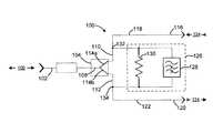
- a splitter device 100includes a provider content input port 102 coupled to a splitter 104 .
- the provider content input port 102is a standard female coaxial port configured to receive a downstream-propagating provider bandwidth 106 , which may be a CATV system, for example.
- An exemplary CATV systemcarries downstream bandwidth in the 50-1,000 MHz range, and also carries an upstream bandwidth in the 7-49 MHz range, represented in FIG. 2 as arrows pointing in both directions.
- the splitter 104which may be a simple circuit, divides an input leg 108 into a first output leg 110 and a second output leg 112 .
- the splitter 104may include a splitter transformer 114 comprising windings 114 a and 114 b on each output leg, in one example.
- the transformer 114may comprise a quarter-wave transmission line in the form of an integrated circuit micro-strip line on each output leg.
- the first output leg 110is coupled to a first user port 116 via a first conductive path 118 .
- the second output leg 112is coupled to a second user port 120 via a second conductive path 122 .
- the first user port 116 and the second user port 120may be configured [for set top boxes, etc.]
- the splitter device 100is adapted to freely transmit data on a home network bandwidth 124 from any port to any other port.
- data on the home network bandwidth 124may be transmitted from the first user port 116 to the second user port 120 , or from the first user port 116 to the input port 102 .
- data on the home network bandwidth 124may be transmitted from the second user port 120 to the first user port 116 , or from the second user port 120 to the input port 102 .
- data on the home network bandwidth 124may be transmitted from the input port 102 to either of the first user port 116 or the second user port 120 .
- the datamay include voice transmission, security, home heating/cooling instructions, and high definition video technologies, for example.
- the home network bandwidth 124occupies an open spectrum bandwidth, that is, in a frequency range outside the provider bandwidth 106 . Referring to the exemplary CATV system above, the home network bandwidth 124 may carry signals in the 1125-1525 MHz range.
- Band selective isolation for the splitter device 100is provided by a band-selective isolation bridge circuit 126 operatively coupled between the first conductive path 118 and the second conductive path 122 . In this manner, the provider bandwidth 106 is isolated from the first user port 116 to the second user port 120 .
- the bridge circuit 126includes a high pass filter 128 .
- the high pass filter 128is configured to attenuate the CATV bandwidth 106 and pass the home network bandwidth 124 .
- the high pass filter 128may block or attenuate frequencies below 1000 MHz, while passing frequencies above 1125 MHz.
- the splitter device 100provides adequate isolation between the first user port 116 and the second user port 120 in the CATV bandwidth, while allowing signals to pass from the first user port 116 to the second user port 120 in the home network bandwidth 124 .
- the bridge circuit 126may further include an additional isolation element 130 such as a resistor disposed in parallel with the bridge circuit 126 .
- the isolation element 130provides isolation between the first conductive path 118 and second conductive path 122 when carrying the provider bandwidth 106 .
- signals transmitted in the provider bandwidth 106enter the splitter device 100 through the input port 102 and propagate down either the first conductive path 118 or the second conductive path 122 .
- Signals propagating down the first conductive path 118pass through node 132 to the first user port 116 .
- Signals passing down the alternate branch of node 132are attenuated by high pass filter 128 .
- Signals propagating down the second conductive path 122pass through node 134 to the second user port 120 .
- signals in the home network bandwidth 124enter the splitter device 100 through the first user port 116 and propagate down the first conductive path 118 to node 132 .
- Signals propagating on the branch towards the provider content input port 102are eventually attenuated as will be explained below.
- Signals propagating down the other branch of node 132pass through the high pass filter 128 towards node 134 and out the second user port 120 .
- a low pass filter(not shown) may be disposed at the point of entry between the input port 102 and the user tap.
- the low pass filteris configured to attenuate the home network bandwidth 124 while passing the provider bandwidth 106 .
- the low pass filter(not shown) may be integrated into the input port 102 and may be selectively activated.
- a bypass leg including the low pass filtermay be controlled by a switch.
- the switchmay be manual, remote, or automatic with a detection feature.
- the switchcould be used to attenuate the home network bandwidth 124 from being transmitted upstream (e.g., out the input port). This embodiment is useful when multiple splitter devices of the present invention are located throughout a household, but only one of them is required to block the home network bandwidth.
- a splitter device located at the point of entryis one example.
- FIG. 3another embodiment of a splitter device 200 includes a provider content input port 202 coupled to a splitter 204 .
- the splitter 204divides an input leg 208 into a first output leg 210 and a second output leg 212 .
- Each output legmay include a first and second transformer winding 214 a and 214 b .
- the first output leg 210is coupled to a first user port 216 via a first conductive path 218 .
- the second output leg 212is coupled to a second user port 220 via a second conductive path 222 .
- Band selective isolation for the splitter device 200is provided by a band-selective isolation bridge circuit 226 operatively coupled between the first conductive path 218 and the second conductive path 222 .
- the bridge circuit 226includes a high pass filter 228 configured to attenuate a CATV bandwidth 206 and pass a home network bandwidth 224 .
- the band-selective isolation bridge circuit 226further includes an additional isolation element 230 such as a resistor disposed in parallel with the bridge circuit 126 .
- the bridge circuit 226 depicted in FIG. 3further includes a low pass filter 236 operatively coupled to the second conductive path 222 .
- the low pass filter 236is disposed between the second output leg 212 of the splitter 204 and the junction or node 238 where the isolation element 230 joins the second conductive path 222 .
- the low pass filter 236is configured to pass the provider bandwidth 206 and attenuate the home network bandwidth 224 .
- signals transmitted in the provider bandwidth 206enter the splitter device 200 through the input port 202 and propagate down either the first conductive path 218 or the second conductive path 222 .
- Signals propagating down the first conductive path 218pass through node 232 to the first user port 216 .
- Signals passing down the alternate branch of node 232are attenuated by high pass filter 228 .
- Signals propagating down the second conductive path 222pass through the low pass filter 236 and node 234 to the second user port 220 .
- signals in the home network bandwidth 224enter the splitter device 200 through the first user port 216 and propagate down the first conductive path 218 to node 232 .
- Signals propagating on the branch towards the provider content input port 202are eventually attenuated as explained above.
- Signals propagating down the other branch of node 232pass through the high pass filter 228 towards node 234 and out the second user port 220 .
- Signals propagating down the other branch of node 234are attenuated by the low pass filter 236 .
- FIG. 4another embodiment of a splitter device 300 includes a provider content input port 302 coupled to a splitter 304 .
- the splitter 304divides an input leg 308 into a first output leg 310 and a second output leg 312 .
- Each output legmay include a first and second transformer winding 314 a and 314 b .
- the first output leg 310is coupled to a first user port 316 via a first conductive path 318 .
- the second output leg 312is coupled to a second user port 320 via a second conductive path 322 .
- Band selective isolation for the splitter device 300is provided by a band-selective isolation bridge circuit 326 operatively coupled between the first conductive path 318 and the second conductive path 322 .
- the bridge circuit 326includes a high pass filter 328 configured to attenuate a CATV bandwidth 306 and pass a home network bandwidth 324 .
- the band-selective isolation bridge circuit 326further includes an additional isolation element 330 such as a resistor disposed in parallel with the bridge circuit 326 .
- the bridge circuit 326 depicted in FIG. 3further includes a low pass filter 336 operatively coupled to the second conductive path 322 between isolation element 330 and a high pass filter 328 .
- signals transmitted in the provider bandwidth 306enter the splitter device 300 through the input port 302 and propagate down either the first conductive path 318 or the second conductive path 322 .
- Signals propagating down the first conductive path 318pass through node 332 to the first user port 316 .
- Signals passing down the alternate branch of node 332are attenuated by high pass filter 328 .
- Signals propagating down the second conductive path 322pass through the low pass filter 336 and node 334 to the second user port 320 .
- Signals passing down the alternate branch of node 334are attenuated by high pass filter 328 .
- signals in the home network bandwidth 324enter the splitter device 300 through the first user port 316 and propagate down the first conductive path 318 to node 332 .
- Signals propagating on the branch towards the provider content input port 302are eventually attenuated as explained above.
- Signals propagating down the other branch of node 332pass through the high pass filter 328 towards node 334 and out the second user port 320 .
- Signals propagating down the other branch of node 334are attenuated by the low pass filter 336 .
- band selective isolationis provided by blocking both the second conductive path 322 and the isolation element 330 from the home network bandwidth 324 .
- FIG. 5another embodiment of a splitter device 400 includes a provider content input port 402 coupled to a splitter 404 .
- the splitter 404divides an input leg 408 into a first output leg 410 and a second output leg 412 .
- Each output legmay include a first and second transformer winding 414 a and 414 b .
- the first output leg 410is coupled to a first user port 416 via a first conductive path 418 .
- the second output leg 412is coupled to a second user port 420 via a second conductive path 422 .
- Band selective isolation for the splitter device 400is provided by a band-selective isolation bridge circuit 426 operatively coupled between the first conductive path 418 and the second conductive path 422 .
- the bridge circuit 426includes a high pass filter 428 configured to attenuate a CATV bandwidth 406 and pass a home network bandwidth 424 .
- the band-selective isolation bridge circuit 426further includes an additional isolation element 430 , such as a resistor, and a low pass filter 436 disposed in parallel with the bridge circuit 426 .
- signals transmitted in the provider bandwidth 406enter the splitter device 400 through the input port 402 and propagate down either the first conductive path 418 or the second conductive path 422 .
- Signals propagating down the first conductive path 418pass through node 432 to the first user port 416 .
- Signals passing down the alternate branch of node 432are attenuated by high pass filter 428 .
- Signals propagating down the second conductive path 422pass through node 440 and node 434 to the second user port 420 .
- Signals passing down the alternate branch of node 434are attenuated by the high pass filter 428 .
- signals in the home network bandwidth 424enter the splitter device 400 through the first user port 416 and propagate down the first conductive path 418 to node 432 .
- Signals propagating on the branch towards the provider content input port 402are eventually attenuated as explained above.
- Signals propagating down the other branch of node 432pass through the high pass filter 428 towards node 434 and out the second user port 420 .
- Signals propagating down the other branch of node 434pass up the second conductive path 422 to third node 440 , and are either attenuated by the low pass filter 436 or the low pass filter disposed between the input port 402 and the user tap.
- the embodiments of the bridge circuit described abovemay be combined.
- the location of the low pass filter 236 illustrated in FIG. 3may be combined with the location of the low pass filter 436 illustrated in FIG. 5 .
- two low pass filtersare provided and the home network bandwidth will be attenuated on the second conductive path and on the leg comprising the isolation element.
- FIG. 6another embodiment of a splitter device 500 includes a bridge circuit 526 that utilizes component symmetry to ensure equal circuit performance whether the home network bandwidth is entering the splitter device from the first user port 516 or the second user port 520 .
- the circuit illustrated in FIG. 5is modified to include a second low pass filter 536 b disposed symmetric along the leg comprising the isolation element 530 opposite the first low pass filter 536 a .
- a home network bandwidth 524 entering from either port 516 or port 520will be attenuated prior to reaching the isolation element 530 .
- the splitter device 600includes a provider content input port 602 coupled to a first splitter 604 .
- the first splitter 604divides an input leg 608 into a first output leg 610 and a second output leg 612 .
- Each output legmay include a first and second transformer winding 614 a and 614 b .
- the first output leg 610is coupled to a first user port 616 via a first conductive path 618 .
- the first user port 616includes a second splitter 642 .
- An input leg 644 of the second splitter 642splits a home network bandwidth 624 entering through the first user port 616 into a first output leg 646 and a second output leg 648 .
- the first output leg 646 of the second splitter 642is coupled to the first conductive path 618
- the second output leg 648is coupled to a bridge circuit 626 , as will be explained below.
- the second output leg 612 of the first splitter 604is coupled to a second user port 620 via a second conductive path 622 .
- the second user port 620includes a third splitter 650 having an input leg 652 and two output legs 654 , 656 .
- the first output leg 654is coupled to the second conductive path 622
- the second output leg 656is coupled to the bridge circuit 626 .
- the bridge circuit 626includes a high pass filter 628 operatively coupled to the second output leg 648 of the second splitter 642 and the second output leg 656 of the third splitter 650 .
- the bridge circuit 626further includes a first ground path element 658 coupled to the second output leg 648 of the second splitter 642 at node 660 .
- the first ground path element 658directs the provider bandwidth 606 to ground and prevents reflections from the high pass filter 628 to the provider bandwidth 606 .
- the first ground path element 658includes a low pass filter 636 a and a termination resistor 662 a .
- the low pass filter 636 ais configured pass the provider bandwidth 606 and attenuate the home network bandwidth 624 .
- the termination resistor 662may be configured to match the impedance of the line load so as to prevent reflections due to impedance mismatch.
- the line loadis 75 ohms
- the termination resistor 662is likewise 75 ohms.
- the bridge circuit 626further includes a second ground path element 664 coupled to the second output leg 656 of the third splitter 650 at node 666 .
- the second ground path element 664includes a low pass filter 636 b and a termination resistor 662 b .
- the second ground path element 664is symmetric to the first ground path element 658 .
- the bridge circuit 626may further include an isolation element 630 such as a resistor disposed in parallel with the bridge circuit 626 .
- the isolation element 630provides isolation between the first conductive path 618 and second conductive path 622 when carrying the provider bandwidth 606 .
- signals transmitted in the provider bandwidth 606enter the splitter device 600 through the input port 602 and propagate down either the first conductive path 618 or the second conductive path 622 .
- Signals propagating down the first conductive path 618enter the second splitter 642 through the first output leg 646 and exit the first user port 616 .
- signals propagating down the second output leg 648enter the third splitter 650 through the first output leg 654 and exit the second user port 620 .
- any of the provider bandwidth 606propagate down the second output leg 656 , it is attenuated at the high pass filter 628 or routed to ground through the first ground path element 664 .
- Provider bandwidth 606 propagating upstreammay enter the second splitter 642 at the first user port 616 and travel up the first output leg 646 and out the provider content input port 602 .
- Upstream bandwidth propagating along the second output leg 648is attenuated at the high pass filter 628 or routed to ground through the first ground path element 658 .
- signals in the home network bandwidth 624enter the splitter device 600 through the second splitter 642 at the first user port 616 and propagate through the high pass filter 628 , through the second output leg 656 of the third splitter 650 , and out the second user port 620 .
- Signals in the home network bandwidth 624 propagating up the first output leg 646 of the second splitter 642 , or propagating up the first output leg 654 of the third splitter 650pass out the provider content input port 602 and are attenuated by the low pass filter (not shown) disposed between the input port and the user tap.
- the low pass filter 636 ais a hybrid parallel LC arrangement in which inductors L 9 and L 1 along with capacitors C 1 and C 3 increase the isolation between the low pass filter(s) and the high pass filter 628 .
- L 2 /C 4 , L 3 /C 6 , L 4 /C 8 and capacitors C 5 , C 7 , and C 9collectively form an elliptic filter.
- Other filter designs, such as Butterworth or Chebyshev,are equally operable but may require additional components to implement.
- the low pass filter 636 bis symmetric to filter 636 a .
- inductors L 10 and L 11along with capacitors C 2 and C 18 increase the isolation between the low pass filter(s) and the high pass filter 628 , while L 12 /C 19 , L 13 /C 21 , L 14 /C 23 and capacitors C 20 , C 22 , and C 24 collectively form an elliptic filter.
- High pass filter 628includes capacitors C 10 , C 11 , C 12 , C 13 , C 14 , C 15 , C 16 and C 17 and inductors L 5 , L 6 , L 7 , and L 8 to form a filter path that passes signals in the frequency range of the home network bandwidth (e.g., 1125 to 1525 MHz).
- Capacitors C 10 , C 12 , C 14 and C 16are connected in series between the input path and output path. Series connections of L 5 /C 11 , L 6 /C 13 , L 7 /C 15 and L 8 /C 17 connect to ground the node between C 10 and C 12 , the node between C 12 and C 14 , the node between C 14 and C 16 , and the node between C 16 and node 666 , respectively.
- This filteris an operable embodiment, but other filter designs are operable with the present invention as well.
- the schematic of FIG. 8is approximately symmetric in either direction, although individual component values need not be symmetric. Symmetry is not necessary to the present invention, but has the advantage of symmetric return loss at the input port and the output port as a function of frequency.
- FIG. 8The embodiment of FIG. 8 is designed to minimize insertion losses and maintain a return loss with a magnitude greater than 25 dB in all frequency regions for which signals of interest are transmitted. Return loss in the transition portions of the frequency response, in which no information is contained, may not be significant.
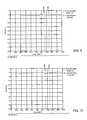
- FIG. 9plots the insertion loss from the provider content input port 602 to the first user port 616 as a function of frequency. The insertion loss is less than 7 dB.
- FIG. 10plots the insertion loss from the provider content input port 602 to the second user port 620 , and the insertion loss is less than 7 dB.
- FIG. 11plots the return loss at the first user port 616 as a function of frequency.
- the return lossis greater than 25 dB for the provider bandwidth 606 (e.g., 5 to 1000.5 MHz) and the home network bandwidth 624 (e.g., frequencies greater than 1125 MHz).
- FIG. 12plots the return loss at the second user port 620 .
- the return lossis greater than 25 dB for the provider bandwidth 606 and the home network bandwidth 624 .
- FIG. 13plots the insertion loss from the first user port 616 to the second user port 620 as a function of frequency to illustrate the isolation between the two ports.
- Isolation in the provider bandwidth 606is very high; greater than 35 dB below 1000.5 MHz.
- isolation in the home network bandwidth 624e.g., 1125 to 1525 MHz is quite low; less than approximately 7 dB.
- a bridge circuit 726 of the present inventionmay be used as a splitter adapter 768 .
- the splitter adapter 768includes two provider content input ports 702 a , 702 b to mate with the output of a standard coaxial cable splitter device (not shown).
- the splitter adapter 768includes a first and second user ports 716 and 720 , respectively.
- the first user port 716includes a first splitter 742 and the second user port 720 includes a second splitter 750 , as described in the embodiment illustrated in FIG. 7 .
- the first splitter 742includes an input leg 744 coupled to the first user port 716 , and two output legs 746 , 748 .
- the first output leg 746is coupled to the provider content input port 702 a
- the second output leg 748is coupled to the input of the bridge circuit 726 .
- the second splitter 750includes an input leg 744 coupled to the second user port 720 , and two output legs 754 , 756 .
- the first output leg 754is coupled to the provider content input port 702 b
- the second output leg 756is coupled to the output of the bridge circuit 726 .
- the bridge circuit 726may be arranged as described with reference to FIGS. 7 and 8 .
Landscapes
- Engineering & Computer Science (AREA)
- Multimedia (AREA)
- Automation & Control Theory (AREA)
- Computer Networks & Wireless Communication (AREA)
- Signal Processing (AREA)
- Two-Way Televisions, Distribution Of Moving Picture Or The Like (AREA)
Abstract
Description
Claims (32)
Priority Applications (4)
| Application Number | Priority Date | Filing Date | Title |
|---|---|---|---|
| US12/693,689US8350641B2 (en) | 2010-01-26 | 2010-01-26 | Band selective isolation bridge for splitter |
| TW100102708ATW201145899A (en) | 2010-01-26 | 2011-01-25 | Band selective isolation bridge for splitter |
| CN2011200968298UCN202111725U (en) | 2010-01-26 | 2011-01-26 | Splitter equipment and splitter adapter |
| CN2011100844779ACN102136978A (en) | 2010-01-26 | 2011-01-26 | Band selective isolation bridge for splitter |
Applications Claiming Priority (1)
| Application Number | Priority Date | Filing Date | Title |
|---|---|---|---|
| US12/693,689US8350641B2 (en) | 2010-01-26 | 2010-01-26 | Band selective isolation bridge for splitter |
Publications (2)
| Publication Number | Publication Date |
|---|---|
| US20110181371A1 US20110181371A1 (en) | 2011-07-28 |
| US8350641B2true US8350641B2 (en) | 2013-01-08 |
Family
ID=44296638
Family Applications (1)
| Application Number | Title | Priority Date | Filing Date |
|---|---|---|---|
| US12/693,689Active2030-12-13US8350641B2 (en) | 2010-01-26 | 2010-01-26 | Band selective isolation bridge for splitter |
Country Status (3)
| Country | Link |
|---|---|
| US (1) | US8350641B2 (en) |
| CN (2) | CN202111725U (en) |
| TW (1) | TW201145899A (en) |
Cited By (6)
| Publication number | Priority date | Publication date | Assignee | Title |
|---|---|---|---|---|
| US20120213083A1 (en)* | 2011-02-21 | 2012-08-23 | John Mezzalingua Associates, Inc. | Home network test circuit |
| US20130181789A1 (en)* | 2010-09-14 | 2013-07-18 | Technetix Group Limited | Signal splitter for use in moca/catv networks |
| US9264012B2 (en) | 2012-06-25 | 2016-02-16 | Ppc Broadband, Inc. | Radio frequency signal splitter |
| US9705175B2 (en)* | 2015-05-08 | 2017-07-11 | Alcatel-Lucent Usa Inc. | Waveguide power dividers |
| US9729935B1 (en)* | 2015-03-02 | 2017-08-08 | The Directv Group, Inc. | Switching splitter and method of operating the same |
| US10462419B2 (en) | 2017-01-13 | 2019-10-29 | Commscope Technologies Llc | Hybrid splitter passing CATV+MoCA and MoCA signals |
Families Citing this family (22)
| Publication number | Priority date | Publication date | Assignee | Title |
|---|---|---|---|---|
| US10154302B2 (en) | 2008-10-13 | 2018-12-11 | Ppc Broadband, Inc. | CATV entry adapter and method for distributing CATV and in-home entertainment signals |
| US9351051B2 (en) | 2008-10-13 | 2016-05-24 | Ppc Broadband, Inc. | CATV entry adapter and method for distributing CATV and in-home entertainment signals |
| US8356322B2 (en) | 2009-09-21 | 2013-01-15 | John Mezzalingua Associates, Inc. | Passive multi-port entry adapter and method for preserving downstream CATV signal strength within in-home network |
| US8510782B2 (en) | 2008-10-21 | 2013-08-13 | Ppc Broadband, Inc. | CATV entry adapter and method for preventing interference with eMTA equipment from MoCA Signals |
| US11910052B2 (en) | 2008-10-21 | 2024-02-20 | Ppc Broadband, Inc. | Entry device for communicating external network signals and in-home network signals |
| US8487717B2 (en) | 2010-02-01 | 2013-07-16 | Ppc Broadband, Inc. | Multipath mitigation circuit for home network |
| US8797045B2 (en)* | 2011-03-25 | 2014-08-05 | Doble Lemke Gmbh | Device for detecting partial discharge in an insulation system of rotary electric machines |
| US9356796B2 (en)* | 2013-04-23 | 2016-05-31 | Times Fiber Communications, Inc. | MoCA gateway splitter |
| US9743038B2 (en) | 2014-04-02 | 2017-08-22 | Commscope, Inc. Of North Carolina | Radio frequency power divider networks having MoCA bypass circuits and related methods |
| CA3028756A1 (en) | 2016-06-30 | 2018-01-04 | Ppc Broadband, Inc. | Passive enhanced moca entry device |
| US10701569B2 (en) | 2016-10-03 | 2020-06-30 | Enseo, Inc. | Self-calibrating RF network and system and method for use of the same |
| US10425617B2 (en) | 2016-10-03 | 2019-09-24 | Enseo, Inc. | Distribution element for a self-calibrating RF network and system and method for use of the same |
| US11831934B2 (en) | 2022-01-11 | 2023-11-28 | Enseo, Llc | Set-top box with self-monitoring and system and method for use of same |
| US12212792B2 (en) | 2016-10-28 | 2025-01-28 | Enseo, Llc | Set-top box with self-monitoring and system and method for use of same |
| US10798374B2 (en) | 2016-10-28 | 2020-10-06 | Enseo, Inc. | Set-top box with self-monitoring and system and method for use of same |
| US10742926B2 (en)* | 2017-10-06 | 2020-08-11 | Ppc Broadband, Inc. | Network interface device |
| WO2019143609A1 (en)* | 2018-01-17 | 2019-07-25 | Ppc Broadband, Inc. | Reflection-less in-home network adapter |
| WO2019143613A2 (en)* | 2018-01-19 | 2019-07-25 | Ppc Broadband, Inc. | Systems and methods for extending an in-home splitter network |
| CN111527707A (en)* | 2018-01-19 | 2020-08-11 | Ppc宽带股份有限公司 | Double-network splitter |
| WO2020167700A1 (en)* | 2019-02-11 | 2020-08-20 | Commscope Technologies Llc | Catv device with resistive signal distribution network |
| WO2020206200A1 (en)* | 2019-04-03 | 2020-10-08 | Ppc Broadband, Inc. | Passive entry adapter system for a catv network |
| BR112022025905A2 (en)* | 2020-06-23 | 2023-03-14 | Ppc Broadband Inc | FREQUENCY CONVERTER CABLE NETWORK SIGNAL TRANSMISSION DEVICES |
Citations (149)
| Publication number | Priority date | Publication date | Assignee | Title |
|---|---|---|---|---|
| US3790909A (en) | 1973-01-26 | 1974-02-05 | Gte Sylvania Inc | Varactor tuner band switch circuitry |
| US3939431A (en) | 1974-11-25 | 1976-02-17 | Motorola, Inc. | Muting circuit for a radio receiver |
| US4027219A (en) | 1974-11-14 | 1977-05-31 | U.S. Philips Corporation | Device for displaying color television images |
| US4306403A (en) | 1980-10-17 | 1981-12-22 | Deere & Company | Overload sensor for a cotton harvester unit drive |
| US4344499A (en) | 1978-12-08 | 1982-08-17 | C. Van Der Lely N.V. | Tractor with anti-slipping and overloading controls |
| US4512033A (en) | 1982-11-29 | 1985-04-16 | C-Cor Labs, Inc. | Remote level adjustment system for use in a multi-terminal communications system |
| US4520508A (en) | 1982-12-21 | 1985-05-28 | General Instrument Corporation | Subscriber terminal for monitoring radio-frequency signal ingress into cable television systems |
| US4648123A (en) | 1982-11-29 | 1987-03-03 | C-Cor Labs, Inc. | Remote level measurement system for use in a multi-terminal communications system |
| US4677390A (en) | 1985-05-31 | 1987-06-30 | Texscan Corporation | Low-power feedforward amplifier |
| US4715012A (en) | 1980-10-15 | 1987-12-22 | Massey-Ferguson Services N.V. | Electronic tractor control |
| US4961218A (en) | 1989-05-17 | 1990-10-02 | Tollgrade Communications, Inc. | Enhanced line powered amplifier |
| US4982440A (en) | 1988-04-21 | 1991-01-01 | Videotron Ltee | CATV network with addressable filters receiving MSK upstream signals |
| US5010399A (en) | 1989-07-14 | 1991-04-23 | Inline Connection Corporation | Video transmission and control system utilizing internal telephone lines |
| US5126840A (en) | 1988-04-21 | 1992-06-30 | Videotron Ltee | Filter circuit receiving upstream signals for use in a CATV network |
| US5214505A (en) | 1991-04-08 | 1993-05-25 | Hughes Aircraft Company | Automatic rf equalization in passenger aircraft video distribution system |
| US5231660A (en) | 1988-03-10 | 1993-07-27 | Scientific-Atlanta, Inc. | Compensation control for off-premises CATV system |
| US5369642A (en) | 1992-05-29 | 1994-11-29 | Nec Corporation | Switcher for redundant signal transmission system |
| US5485630A (en) | 1994-03-31 | 1996-01-16 | Panasonic Technologies, Inc. | Audio/video distribution system |
| US5548255A (en) | 1995-06-23 | 1996-08-20 | Microphase Corporation | Compact diplexer connection circuit |
| US5557319A (en) | 1994-12-28 | 1996-09-17 | U.S. Philips Corporation | Subscriber return system for CATV full service networks |
| US5557510A (en) | 1993-11-29 | 1996-09-17 | Gehl Company | Control system for a large round baler |
| US5719792A (en) | 1995-10-17 | 1998-02-17 | Trilithic, Inc. | Isolator |
| US5740044A (en) | 1995-06-16 | 1998-04-14 | Caterpillar Inc. | Torque limiting power take off control and method of operating same |
| US5745836A (en) | 1995-09-01 | 1998-04-28 | Cable Television Laboratories, Inc. | Undesirable energy suppression system in a contention based communication network |
| US5815794A (en) | 1995-09-01 | 1998-09-29 | Cable Television Laboratories, Inc. | Undesirable energy suppression system in the return path of a bidirectional cable network having dynamically allocated time slots |
| US5818825A (en) | 1995-11-29 | 1998-10-06 | Motorola, Inc. | Method and apparatus for assigning communications channels in a cable telephony system |
| US5839052A (en) | 1996-02-08 | 1998-11-17 | Qualcom Incorporated | Method and apparatus for integration of a wireless communication system with a cable television system |
| US5893024A (en) | 1996-08-13 | 1999-04-06 | Motorola, Inc. | Data communication apparatus and method thereof |
| US5937330A (en) | 1997-02-18 | 1999-08-10 | General Instrument Corporation | Settop terminal controlled return path filter for minimizing noise ingress on bidirectional cable systems |
| US5950111A (en) | 1997-09-25 | 1999-09-07 | Lucent Technologies Inc. | Self-terminating coaxial to unshielded twisted-pair cable passive CATV distribution panel |
| US5970053A (en) | 1996-12-24 | 1999-10-19 | Rdl, Inc. | Method and apparatus for controlling peak factor of coherent frequency-division-multiplexed systems |
| US6014547A (en) | 1997-04-28 | 2000-01-11 | General Instrument Corporation | System for enhancing the performance of a CATV settop terminal |
| US6012271A (en) | 1997-01-17 | 2000-01-11 | Welger Gmbh | Round baler with a load sensor for actuating the wrapping apparatus and for turning off at least one delivery element |
| US6049693A (en) | 1996-08-15 | 2000-04-11 | Com21, Inc. | Upstream ingress noise blocking filter for cable television system |
| WO2000024124A1 (en) | 1998-10-22 | 2000-04-27 | Ericsson, Inc. | Dual-band, dual-mode power amplifier with reduced power loss |
| US6069960A (en) | 1996-09-05 | 2000-05-30 | Sony Corporation | Connector device for information-handling apparatus and connector device for stereophonic audio/video apparatus |
| US6101932A (en) | 1997-11-05 | 2000-08-15 | Welger Gmbh | Channel bale press for agricultural harvest crop and device and method for controlling operation of the bale press |
| US6128040A (en) | 1988-02-12 | 2000-10-03 | Canon Kabushiki Kaisha | Record medium erasing device with variable control in accordance with power supply characteristics |
| US6129187A (en) | 1996-11-15 | 2000-10-10 | Agco Sa | PTO shaft monitoring and control system |
| US6169569B1 (en) | 1998-05-22 | 2001-01-02 | Temic Telefumken | Cable modem tuner |
| US6173225B1 (en) | 1999-04-20 | 2001-01-09 | Case Corporation | Power takeoff control system |
| US6185432B1 (en) | 1997-10-13 | 2001-02-06 | Qualcomm Incorporated | System and method for selecting power control modes |
| US6205138B1 (en) | 1998-04-24 | 2001-03-20 | International Business Machines Corporation | Broadband any point to any point switch matrix |
| JP2001177580A (en) | 1999-12-20 | 2001-06-29 | Sony Corp | Impedance adapting system |
| US20010016950A1 (en) | 2000-02-14 | 2001-08-23 | Syuuji Matsuura | Cable modem tuner |
| WO2001072005A1 (en) | 2000-03-17 | 2001-09-27 | Transcorp Systems Pty Ltd | Digital data splitter with switch and automatic termination restoration |
| US6348955B1 (en) | 1998-02-23 | 2002-02-19 | Zenith Electronics Corporation | Tuner with switched analog and digital demodulators |
| US6348837B1 (en) | 2000-08-08 | 2002-02-19 | Scientific-Atlanta, Inc. | Bi-directional amplifier having a single gain block for amplifying both forward and reverse signals |
| US6373349B2 (en) | 2000-03-17 | 2002-04-16 | Bae Systems Information And Electronic Systems Integration Inc. | Reconfigurable diplexer for communications applications |
| US6377316B1 (en) | 1998-02-23 | 2002-04-23 | Zenith Electronics Corporation | Tuner with switched analog and digital modulators |
| WO2002033969A1 (en) | 2000-10-16 | 2002-04-25 | Xtend Networks Ltd. | System and method for expanding the operational bandwidth of a communication system |
| US6388539B1 (en) | 2001-04-16 | 2002-05-14 | At&T Corp. | Broadband switch/coupler |
| US6425132B1 (en) | 1998-04-06 | 2002-07-23 | Wavetek Corporation | Ingress testing of CATV system utilizing remote selection of CATV node |
| US6430904B1 (en) | 2001-05-09 | 2002-08-13 | Deere & Company | Platform auger torque sensing brake activation |
| US20020141347A1 (en) | 2001-03-30 | 2002-10-03 | Harp Jeffrey C. | System and method of reducing ingress noise |
| US20020144292A1 (en) | 2001-02-19 | 2002-10-03 | Jun Uemura | Bi-directional CATV system, line equipment, center equipment |
| US20020166124A1 (en) | 2001-05-04 | 2002-11-07 | Itzhak Gurantz | Network interface device and broadband local area network using coaxial cable |
| WO2002091676A1 (en) | 2001-05-08 | 2002-11-14 | Hoseo Telecom Co., Ltd | Subscriber tap-off capable of monitoring state of transmission line at subscriber end, and remote control system and method using the same |
| US20020174423A1 (en) | 2001-05-17 | 2002-11-21 | David Fifield | Apparatus for transporting home networking frame-based communications signals over coaxial cables |
| US6495998B1 (en) | 2000-09-28 | 2002-12-17 | Sunrise Telecom Corp. | Selectable band-pass filtering apparatus and method |
| US6498925B1 (en) | 1999-05-13 | 2002-12-24 | Denso Corporation | Transmit power control circuit |
| US6510152B1 (en) | 1997-12-31 | 2003-01-21 | At&T Corp. | Coaxial cable/twisted pair fed, integrated residence gateway controlled, set-top box |
| US6546705B2 (en) | 2000-05-13 | 2003-04-15 | New Holland North America, Inc. | Method and apparatus for controlling a tractor/baler combination |
| US20030084458A1 (en) | 1999-12-14 | 2003-05-01 | Ljungdahl Kjell Arne | Local network forming part of a cable tv system |
| US6560778B1 (en) | 1999-03-29 | 2003-05-06 | Masprodenkoh Kabushikikaisha | Tap device of cable broadcasting system |
| US6570928B1 (en) | 1999-01-05 | 2003-05-27 | Masprodenkoh Kabushikikaisha | Cable broadcasting system |
| US6587012B1 (en) | 1999-10-01 | 2003-07-01 | Arris International, Inc. | Automatic slope and gain (ASG) detector technique including a pilot signal |
| US6594827B1 (en) | 1996-07-19 | 2003-07-15 | Telefonaktiebolaget Lm Ericsson (Publ) | Method and an arrangement for integrated radio telecommunication via a CATV network |
| US6622304B1 (en) | 1996-09-09 | 2003-09-16 | Thomas W. Carhart | Interface system for computing apparatus and communications stations |
| US6640338B1 (en) | 1999-01-27 | 2003-10-28 | Masprodenkoh Kabushikikaisha | Electronic device for cable broadcasting system |
| US6678893B1 (en) | 1997-12-26 | 2004-01-13 | Samsung Electronics Co., Ltd. | Bidirectional trunk amplifier and cable modem for cable hybrid fiber and coax network which utilizes an upstream pilot signal |
| US6683513B2 (en) | 2000-10-26 | 2004-01-27 | Paratek Microwave, Inc. | Electronically tunable RF diplexers tuned by tunable capacitors |
| JP2004080483A (en) | 2002-08-20 | 2004-03-11 | Ntt Communications Kk | Adapter for VoIP |
| US6725462B1 (en) | 2000-04-19 | 2004-04-20 | At&T Corp. | Optimizing upstream transmission in a cable television distribution plant |
| US6728968B1 (en) | 1999-06-17 | 2004-04-27 | Fujitsu Limited | Upward-joining-noise decreasing method and apparatus |
| US6757910B1 (en) | 2000-06-08 | 2004-06-29 | C-Cor.Net Corporation | Adaptive filter for reducing ingress noise in CATV return signals |
| US6758292B2 (en) | 2002-08-12 | 2004-07-06 | Deere & Company | Interlock system and a detent switch therefor |
| US20040147273A1 (en) | 2003-01-28 | 2004-07-29 | Morphy William F. | Vehicle intercom controller |
| US20040172659A1 (en) | 2001-07-13 | 2004-09-02 | Ljungdahl Kjell Arne | Arrangement for reduction of noise transmitted from a local cable tv network |
| US6804828B1 (en) | 1998-12-03 | 2004-10-12 | Masprodenkoh Kabushikikaisha | Tap device of cable broadcasting system |
| US20040229561A1 (en) | 2003-02-28 | 2004-11-18 | Cowley Nicholas Paul | Tuner |
| US20040244053A1 (en) | 2001-08-24 | 2004-12-02 | Harel Golombek | Cable tv network frequency range extension with passive bypass device |
| JP2005005875A (en) | 2003-06-10 | 2005-01-06 | Nec Tohoku Ltd | VoIP SWITCHING DEVICE |
| US6845232B2 (en) | 2002-03-25 | 2005-01-18 | Broadcom Corporation | Analog peak detection circuitry for radio receivers |
| US6843044B2 (en) | 2002-09-06 | 2005-01-18 | Deere & Company | Detection arrangement for the detection of a crop jam in a harvesting machine |
| US20050034168A1 (en) | 1993-05-28 | 2005-02-10 | Mediaone Group, Inc. | Method and apparatus for delivering secured telephony service in a hybrid coaxial cable network |
| US20050047051A1 (en) | 2003-08-26 | 2005-03-03 | Eagle Comtronics, Inc. | Voltage limiter for coaxial cable carrying RF signals and voltage |
| US6868552B1 (en) | 1999-06-07 | 2005-03-15 | Fujitsu Limited | Ingress noise control system and ingress noise blocking device |
| US6877166B1 (en) | 2000-01-18 | 2005-04-05 | Cisco Technology, Inc. | Intelligent power level adjustment for cable modems in presence of noise |
| US20050144649A1 (en) | 2003-11-25 | 2005-06-30 | James Bertonis | Apparatus and method for reduction of wireless links noise injection to a DOCSIS cable modem service |
| US6915530B1 (en) | 1994-11-30 | 2005-07-05 | General Instrument Corporation | Ingress detection and characterization by time/frequency map |
| WO2005062611A1 (en) | 2003-12-22 | 2005-07-07 | Vector Sp Z O.O. | Data transmission method and data transmission device |
| US6920614B1 (en) | 1995-07-17 | 2005-07-19 | Gateway Inc. | Computer user interface for product selection |
| US6928175B1 (en) | 2000-06-14 | 2005-08-09 | Creative Technology Ltd. | Audio system with optional auto-switching secondary connector, and method for same |
| US20050183130A1 (en) | 2004-02-12 | 2005-08-18 | Sadja Aran L. | Cable diagnostic and monitoring system |
| US6942595B2 (en) | 2001-09-15 | 2005-09-13 | Cnh America Llc | Control system for the drive of a pto for an agricultural vehicle |
| US20050283815A1 (en) | 2004-06-01 | 2005-12-22 | Brooks Paul D | Apparatus and methods for network interface and spectrum management |
| US20050289632A1 (en) | 2004-06-01 | 2005-12-29 | Brooks Paul D | Controlled isolation splitter apparatus and methods |
| US20060015921A1 (en) | 2004-07-19 | 2006-01-19 | Jay Vaughan | VoIP drop amplifier |
| US7003275B1 (en) | 2000-05-18 | 2006-02-21 | Broadband Innovations, Inc. | Agile frequency converter for multichannel systems using IF-RF level exhange and tunable filters |
| US20060041918A9 (en) | 1999-08-31 | 2006-02-23 | Currivan Bruce J | Signal processing under attenuated transmission conditions |
| US7029293B2 (en) | 2004-08-20 | 2006-04-18 | Extreme Broadband Engineering, Llc | Ground block connector |
| US7039432B2 (en) | 2001-12-04 | 2006-05-02 | General Instrument Corporation | Dynamic upstream attenuation for ingress noise reduction |
| US7048106B2 (en) | 2004-03-26 | 2006-05-23 | Cnh America Llc | Power take-off control system and method |
| US20060191359A1 (en) | 2005-01-21 | 2006-08-31 | Nicolai Tarasinski | Agricultural machine with PTO torque limiting feature |
| US20060205442A1 (en) | 2005-03-10 | 2006-09-14 | Neil Phillips | Bi-directional amplifier with non-interruptible port |
| US7127734B1 (en) | 1999-04-12 | 2006-10-24 | Texas Instruments Incorporated | System and methods for home network communications |
| US20060241838A1 (en) | 2005-04-20 | 2006-10-26 | Marcello Mongiardo | Input device for agricultural vehicle information display |
| US20060282871A1 (en) | 2005-06-13 | 2006-12-14 | Yao-Tsan Yo | Distribution method for noise control |
| US7162731B2 (en) | 2002-02-07 | 2007-01-09 | Advent Networks, Inc. | Radio frequency characterization of cable plant and corresponding calibration of communication equipment communicating via the cable plant |
| US20070076746A1 (en) | 2005-09-14 | 2007-04-05 | Faska Thomas S | Device, system, and method for transporting data using combined broadband and legacy network infrastructures |
| JP2007166109A (en) | 2005-12-12 | 2007-06-28 | Matsushita Electric Works Ltd | Branch device of transmission system, and transmission system |
| JP2007166110A (en) | 2005-12-12 | 2007-06-28 | Matsushita Electric Works Ltd | Transmission system and branch device thereof |
| US7254827B1 (en) | 2000-05-08 | 2007-08-07 | Sunrise Telecom Incorporated | Ingress monitoring system and method |
| US7283479B2 (en) | 2000-02-16 | 2007-10-16 | Spacenet Proxilliant Systems Ab | Cable TV system or other similar communication system |
| US20070288982A1 (en) | 2006-06-13 | 2007-12-13 | Comcast Cable Holdings, Llc | Dynamic ingress arrester |
| US20070288981A1 (en) | 2006-06-13 | 2007-12-13 | Hwa Lin Electronic (Shenzhen)Co., Ltd. | CATV system and automatic noise controller |
| US20080022344A1 (en) | 2006-07-07 | 2008-01-24 | Scientific-Atlanta, Inc. | Format Converter with Smart Multitap with Digital Forward and Reverse |
| US20080040764A1 (en) | 2001-07-20 | 2008-02-14 | Hillel Weinstein | System, apparatus and method for expanding the operational bandwidth of a communication system |
| US20080120667A1 (en) | 2006-11-17 | 2008-05-22 | Texas Instruments Incorporated | Hybrid mpeg/ip digital cable gateway device and architecture associated therewith |
| US20080127287A1 (en) | 2006-11-28 | 2008-05-29 | John Mezzalingua Associates, Inc. | Apparatus and method for embedding/detecting an auxiliary signal within a catv traffic stream |
| US7399255B1 (en) | 2005-06-10 | 2008-07-15 | Polaris Industries Inc. | Engine and transmission control system and method for a vehicle accessory |
| US7404355B2 (en) | 2006-01-31 | 2008-07-29 | Deere & Company | Tractor and baler combination with automatic baling and tractor halt control |
| US7416068B2 (en) | 2004-11-03 | 2008-08-26 | Borgwarner Inc. | Power take-off clutch control system |
| US20080235750A1 (en) | 2007-03-19 | 2008-09-25 | Emerson Network Power Connectivity Solutions | Band switchable amplifier system |
| US20080247401A1 (en) | 2007-04-06 | 2008-10-09 | Texas Instruments Incorporated | Remote Access to Home Communication Services |
| US20080247541A1 (en) | 2006-03-16 | 2008-10-09 | Chris Cholas | Methods and apparatus for connecting a cable network to other network and/or devices |
| US20080271094A1 (en) | 2000-08-30 | 2008-10-30 | Broadcom Corporation | Home network system and method |
| US7454252B2 (en) | 2006-03-08 | 2008-11-18 | Moore Industries International, Inc. | Redundant fieldbus system |
| US7464526B2 (en) | 2001-09-14 | 2008-12-16 | Gkn Walterscheid Gmbh | Drive assembly for locking one or several operating units of an agricultural implement or of a self-propelled implement |
| US20080313691A1 (en) | 2007-06-13 | 2008-12-18 | Chris Cholas | Premises gateway apparatus and methods for use in a content-based network |
| US20090031391A1 (en) | 2007-03-08 | 2009-01-29 | Emerson Network Power Connectivity Solutions | Electronically controlled catv system |
| US20090047917A1 (en) | 2005-03-10 | 2009-02-19 | Phillips Neil P | Signal Amplifiers Having Non-Interruptible Communication Paths |
| US7505819B2 (en) | 2006-02-08 | 2009-03-17 | Moore Industries International, Inc. | Redundant fieldbus system |
| US20090077608A1 (en) | 2007-09-14 | 2009-03-19 | Romerein Robert L | Constant input port impedance for CATV amplifier with passive modem port |
| US20090113510A1 (en) | 2005-10-12 | 2009-04-30 | Paul Gothard Knutson | Band Switchable Taps and Amplifier for Use in a Cable System |
| US20090165070A1 (en) | 2007-12-19 | 2009-06-25 | Broadcom Corporation | SYSTEMS AND METHODS FOR PROVIDING A MoCA COMPATABILITY STRATEGY |
| US20090180782A1 (en) | 2008-01-14 | 2009-07-16 | Tellabs Vienna, Inc. | Apparatus, system, computer program, and method for providing a multimedia-over-coax-alliance network in conjunction with an optical network |
| US20090320086A1 (en) | 2008-06-23 | 2009-12-24 | Technetix Group Limited | Loss reduction in a coaxial network |
| US20100017842A1 (en) | 2008-07-17 | 2010-01-21 | Wells Chad T | Passive-Active Terminal Adapter and Method Having Automatic Return Loss Control |
| US7675381B2 (en) | 2007-12-12 | 2010-03-09 | Soontai Tech Co., Ltd. | Modulized wave filter |
| US20100095344A1 (en) | 2008-10-13 | 2010-04-15 | Newby Charles F | Ingress Noise Inhibiting Network Interface Device and Method for Cable Television Networks |
| US20100100918A1 (en) | 2008-10-21 | 2010-04-22 | Egan Jr John M | Multi-Port Entry Adapter, Hub and Method for Interfacing a CATV Network and a MoCA Network |
| US20100125877A1 (en) | 2008-10-21 | 2010-05-20 | Wells Chad T | CATV Entry Adapter and Method for Preventing Interference with eMTA Equipment from MoCA Signals |
| US20100146564A1 (en) | 2008-10-21 | 2010-06-10 | Halik Gregory F | CATV Entry Adapter and Method Utilizing Directional Couplers for MoCA Signal Communication |
| US20100225813A1 (en) | 2009-03-03 | 2010-09-09 | Hitachi Consumer Electronics Co., Ltd. | Television receiver |
| US20110072472A1 (en) | 2009-09-21 | 2011-03-24 | Wells Chad T | Passive Multi-Port Entry Adapter and Method for Preserving Downstream CATV Signal Strength within In-Home Network |
| US20120054819A1 (en) | 2010-08-30 | 2012-03-01 | John Mezzalingua Associates, Inc. | Home network frequency conditioning device and method |
| US20120054805A1 (en) | 2010-08-30 | 2012-03-01 | John Mezzalingua Associates, Inc. | Home network frequency conditioning device |
- 2010
- 2010-01-26USUS12/693,689patent/US8350641B2/enactiveActive
- 2011
- 2011-01-25TWTW100102708Apatent/TW201145899A/enunknown
- 2011-01-26CNCN2011200968298Upatent/CN202111725U/ennot_activeExpired - Fee Related
- 2011-01-26CNCN2011100844779Apatent/CN102136978A/enactivePending
Patent Citations (152)
| Publication number | Priority date | Publication date | Assignee | Title |
|---|---|---|---|---|
| US3790909A (en) | 1973-01-26 | 1974-02-05 | Gte Sylvania Inc | Varactor tuner band switch circuitry |
| US4027219A (en) | 1974-11-14 | 1977-05-31 | U.S. Philips Corporation | Device for displaying color television images |
| US3939431A (en) | 1974-11-25 | 1976-02-17 | Motorola, Inc. | Muting circuit for a radio receiver |
| US4344499A (en) | 1978-12-08 | 1982-08-17 | C. Van Der Lely N.V. | Tractor with anti-slipping and overloading controls |
| US4715012A (en) | 1980-10-15 | 1987-12-22 | Massey-Ferguson Services N.V. | Electronic tractor control |
| US4306403A (en) | 1980-10-17 | 1981-12-22 | Deere & Company | Overload sensor for a cotton harvester unit drive |
| US4512033A (en) | 1982-11-29 | 1985-04-16 | C-Cor Labs, Inc. | Remote level adjustment system for use in a multi-terminal communications system |
| US4648123A (en) | 1982-11-29 | 1987-03-03 | C-Cor Labs, Inc. | Remote level measurement system for use in a multi-terminal communications system |
| US4520508A (en) | 1982-12-21 | 1985-05-28 | General Instrument Corporation | Subscriber terminal for monitoring radio-frequency signal ingress into cable television systems |
| US4677390A (en) | 1985-05-31 | 1987-06-30 | Texscan Corporation | Low-power feedforward amplifier |
| US6128040A (en) | 1988-02-12 | 2000-10-03 | Canon Kabushiki Kaisha | Record medium erasing device with variable control in accordance with power supply characteristics |
| US5231660A (en) | 1988-03-10 | 1993-07-27 | Scientific-Atlanta, Inc. | Compensation control for off-premises CATV system |
| US4982440A (en) | 1988-04-21 | 1991-01-01 | Videotron Ltee | CATV network with addressable filters receiving MSK upstream signals |
| US5126840A (en) | 1988-04-21 | 1992-06-30 | Videotron Ltee | Filter circuit receiving upstream signals for use in a CATV network |
| US4961218A (en) | 1989-05-17 | 1990-10-02 | Tollgrade Communications, Inc. | Enhanced line powered amplifier |
| US5010399A (en) | 1989-07-14 | 1991-04-23 | Inline Connection Corporation | Video transmission and control system utilizing internal telephone lines |
| US5214505A (en) | 1991-04-08 | 1993-05-25 | Hughes Aircraft Company | Automatic rf equalization in passenger aircraft video distribution system |
| US5369642A (en) | 1992-05-29 | 1994-11-29 | Nec Corporation | Switcher for redundant signal transmission system |
| US20050034168A1 (en) | 1993-05-28 | 2005-02-10 | Mediaone Group, Inc. | Method and apparatus for delivering secured telephony service in a hybrid coaxial cable network |
| US5557510A (en) | 1993-11-29 | 1996-09-17 | Gehl Company | Control system for a large round baler |
| US5485630A (en) | 1994-03-31 | 1996-01-16 | Panasonic Technologies, Inc. | Audio/video distribution system |
| US6915530B1 (en) | 1994-11-30 | 2005-07-05 | General Instrument Corporation | Ingress detection and characterization by time/frequency map |
| US5557319A (en) | 1994-12-28 | 1996-09-17 | U.S. Philips Corporation | Subscriber return system for CATV full service networks |
| US5740044A (en) | 1995-06-16 | 1998-04-14 | Caterpillar Inc. | Torque limiting power take off control and method of operating same |
| US5548255A (en) | 1995-06-23 | 1996-08-20 | Microphase Corporation | Compact diplexer connection circuit |
| US6920614B1 (en) | 1995-07-17 | 2005-07-19 | Gateway Inc. | Computer user interface for product selection |
| US5815794A (en) | 1995-09-01 | 1998-09-29 | Cable Television Laboratories, Inc. | Undesirable energy suppression system in the return path of a bidirectional cable network having dynamically allocated time slots |
| US5745836A (en) | 1995-09-01 | 1998-04-28 | Cable Television Laboratories, Inc. | Undesirable energy suppression system in a contention based communication network |
| US5719792A (en) | 1995-10-17 | 1998-02-17 | Trilithic, Inc. | Isolator |
| US5818825A (en) | 1995-11-29 | 1998-10-06 | Motorola, Inc. | Method and apparatus for assigning communications channels in a cable telephony system |
| US5839052A (en) | 1996-02-08 | 1998-11-17 | Qualcom Incorporated | Method and apparatus for integration of a wireless communication system with a cable television system |
| US6594827B1 (en) | 1996-07-19 | 2003-07-15 | Telefonaktiebolaget Lm Ericsson (Publ) | Method and an arrangement for integrated radio telecommunication via a CATV network |
| US5893024A (en) | 1996-08-13 | 1999-04-06 | Motorola, Inc. | Data communication apparatus and method thereof |
| US6049693A (en) | 1996-08-15 | 2000-04-11 | Com21, Inc. | Upstream ingress noise blocking filter for cable television system |
| US6094211A (en) | 1996-08-15 | 2000-07-25 | Com21, Inc. | TV and data cable system ingress noise blocker |
| US6069960A (en) | 1996-09-05 | 2000-05-30 | Sony Corporation | Connector device for information-handling apparatus and connector device for stereophonic audio/video apparatus |
| US6622304B1 (en) | 1996-09-09 | 2003-09-16 | Thomas W. Carhart | Interface system for computing apparatus and communications stations |
| US6129187A (en) | 1996-11-15 | 2000-10-10 | Agco Sa | PTO shaft monitoring and control system |
| US5970053A (en) | 1996-12-24 | 1999-10-19 | Rdl, Inc. | Method and apparatus for controlling peak factor of coherent frequency-division-multiplexed systems |
| US6012271A (en) | 1997-01-17 | 2000-01-11 | Welger Gmbh | Round baler with a load sensor for actuating the wrapping apparatus and for turning off at least one delivery element |
| US5937330A (en) | 1997-02-18 | 1999-08-10 | General Instrument Corporation | Settop terminal controlled return path filter for minimizing noise ingress on bidirectional cable systems |
| US6014547A (en) | 1997-04-28 | 2000-01-11 | General Instrument Corporation | System for enhancing the performance of a CATV settop terminal |
| US5950111A (en) | 1997-09-25 | 1999-09-07 | Lucent Technologies Inc. | Self-terminating coaxial to unshielded twisted-pair cable passive CATV distribution panel |
| US6185432B1 (en) | 1997-10-13 | 2001-02-06 | Qualcomm Incorporated | System and method for selecting power control modes |
| US6101932A (en) | 1997-11-05 | 2000-08-15 | Welger Gmbh | Channel bale press for agricultural harvest crop and device and method for controlling operation of the bale press |
| US6678893B1 (en) | 1997-12-26 | 2004-01-13 | Samsung Electronics Co., Ltd. | Bidirectional trunk amplifier and cable modem for cable hybrid fiber and coax network which utilizes an upstream pilot signal |
| US6510152B1 (en) | 1997-12-31 | 2003-01-21 | At&T Corp. | Coaxial cable/twisted pair fed, integrated residence gateway controlled, set-top box |
| US6348955B1 (en) | 1998-02-23 | 2002-02-19 | Zenith Electronics Corporation | Tuner with switched analog and digital demodulators |
| US6377316B1 (en) | 1998-02-23 | 2002-04-23 | Zenith Electronics Corporation | Tuner with switched analog and digital modulators |
| US6425132B1 (en) | 1998-04-06 | 2002-07-23 | Wavetek Corporation | Ingress testing of CATV system utilizing remote selection of CATV node |
| US6205138B1 (en) | 1998-04-24 | 2001-03-20 | International Business Machines Corporation | Broadband any point to any point switch matrix |
| US6169569B1 (en) | 1998-05-22 | 2001-01-02 | Temic Telefumken | Cable modem tuner |
| WO2000024124A1 (en) | 1998-10-22 | 2000-04-27 | Ericsson, Inc. | Dual-band, dual-mode power amplifier with reduced power loss |
| US6804828B1 (en) | 1998-12-03 | 2004-10-12 | Masprodenkoh Kabushikikaisha | Tap device of cable broadcasting system |
| US6570928B1 (en) | 1999-01-05 | 2003-05-27 | Masprodenkoh Kabushikikaisha | Cable broadcasting system |
| US6640338B1 (en) | 1999-01-27 | 2003-10-28 | Masprodenkoh Kabushikikaisha | Electronic device for cable broadcasting system |
| US6560778B1 (en) | 1999-03-29 | 2003-05-06 | Masprodenkoh Kabushikikaisha | Tap device of cable broadcasting system |
| US7127734B1 (en) | 1999-04-12 | 2006-10-24 | Texas Instruments Incorporated | System and methods for home network communications |
| US6173225B1 (en) | 1999-04-20 | 2001-01-09 | Case Corporation | Power takeoff control system |
| US6498925B1 (en) | 1999-05-13 | 2002-12-24 | Denso Corporation | Transmit power control circuit |
| US6868552B1 (en) | 1999-06-07 | 2005-03-15 | Fujitsu Limited | Ingress noise control system and ingress noise blocking device |
| US6728968B1 (en) | 1999-06-17 | 2004-04-27 | Fujitsu Limited | Upward-joining-noise decreasing method and apparatus |
| US20060041918A9 (en) | 1999-08-31 | 2006-02-23 | Currivan Bruce J | Signal processing under attenuated transmission conditions |
| US6587012B1 (en) | 1999-10-01 | 2003-07-01 | Arris International, Inc. | Automatic slope and gain (ASG) detector technique including a pilot signal |
| US20030084458A1 (en) | 1999-12-14 | 2003-05-01 | Ljungdahl Kjell Arne | Local network forming part of a cable tv system |
| JP2001177580A (en) | 1999-12-20 | 2001-06-29 | Sony Corp | Impedance adapting system |
| US6877166B1 (en) | 2000-01-18 | 2005-04-05 | Cisco Technology, Inc. | Intelligent power level adjustment for cable modems in presence of noise |
| US20010016950A1 (en) | 2000-02-14 | 2001-08-23 | Syuuji Matsuura | Cable modem tuner |
| US7283479B2 (en) | 2000-02-16 | 2007-10-16 | Spacenet Proxilliant Systems Ab | Cable TV system or other similar communication system |
| US6373349B2 (en) | 2000-03-17 | 2002-04-16 | Bae Systems Information And Electronic Systems Integration Inc. | Reconfigurable diplexer for communications applications |
| WO2001072005A1 (en) | 2000-03-17 | 2001-09-27 | Transcorp Systems Pty Ltd | Digital data splitter with switch and automatic termination restoration |
| US6725462B1 (en) | 2000-04-19 | 2004-04-20 | At&T Corp. | Optimizing upstream transmission in a cable television distribution plant |
| US7254827B1 (en) | 2000-05-08 | 2007-08-07 | Sunrise Telecom Incorporated | Ingress monitoring system and method |
| US6546705B2 (en) | 2000-05-13 | 2003-04-15 | New Holland North America, Inc. | Method and apparatus for controlling a tractor/baler combination |
| US7003275B1 (en) | 2000-05-18 | 2006-02-21 | Broadband Innovations, Inc. | Agile frequency converter for multichannel systems using IF-RF level exhange and tunable filters |
| US6757910B1 (en) | 2000-06-08 | 2004-06-29 | C-Cor.Net Corporation | Adaptive filter for reducing ingress noise in CATV return signals |
| US6928175B1 (en) | 2000-06-14 | 2005-08-09 | Creative Technology Ltd. | Audio system with optional auto-switching secondary connector, and method for same |
| US6348837B1 (en) | 2000-08-08 | 2002-02-19 | Scientific-Atlanta, Inc. | Bi-directional amplifier having a single gain block for amplifying both forward and reverse signals |
| US20080271094A1 (en) | 2000-08-30 | 2008-10-30 | Broadcom Corporation | Home network system and method |
| US6495998B1 (en) | 2000-09-28 | 2002-12-17 | Sunrise Telecom Corp. | Selectable band-pass filtering apparatus and method |
| WO2002033969A1 (en) | 2000-10-16 | 2002-04-25 | Xtend Networks Ltd. | System and method for expanding the operational bandwidth of a communication system |
| US6683513B2 (en) | 2000-10-26 | 2004-01-27 | Paratek Microwave, Inc. | Electronically tunable RF diplexers tuned by tunable capacitors |
| US20020144292A1 (en) | 2001-02-19 | 2002-10-03 | Jun Uemura | Bi-directional CATV system, line equipment, center equipment |
| US20020141347A1 (en) | 2001-03-30 | 2002-10-03 | Harp Jeffrey C. | System and method of reducing ingress noise |
| US6388539B1 (en) | 2001-04-16 | 2002-05-14 | At&T Corp. | Broadband switch/coupler |
| US20020166124A1 (en) | 2001-05-04 | 2002-11-07 | Itzhak Gurantz | Network interface device and broadband local area network using coaxial cable |
| WO2002091676A1 (en) | 2001-05-08 | 2002-11-14 | Hoseo Telecom Co., Ltd | Subscriber tap-off capable of monitoring state of transmission line at subscriber end, and remote control system and method using the same |
| US6430904B1 (en) | 2001-05-09 | 2002-08-13 | Deere & Company | Platform auger torque sensing brake activation |
| US20020174423A1 (en) | 2001-05-17 | 2002-11-21 | David Fifield | Apparatus for transporting home networking frame-based communications signals over coaxial cables |
| US20040172659A1 (en) | 2001-07-13 | 2004-09-02 | Ljungdahl Kjell Arne | Arrangement for reduction of noise transmitted from a local cable tv network |
| US20080040764A1 (en) | 2001-07-20 | 2008-02-14 | Hillel Weinstein | System, apparatus and method for expanding the operational bandwidth of a communication system |
| US20040244053A1 (en) | 2001-08-24 | 2004-12-02 | Harel Golombek | Cable tv network frequency range extension with passive bypass device |
| US7464526B2 (en) | 2001-09-14 | 2008-12-16 | Gkn Walterscheid Gmbh | Drive assembly for locking one or several operating units of an agricultural implement or of a self-propelled implement |
| US6942595B2 (en) | 2001-09-15 | 2005-09-13 | Cnh America Llc | Control system for the drive of a pto for an agricultural vehicle |
| US7742777B2 (en) | 2001-12-04 | 2010-06-22 | General Instrument Corporation | Dynamic upstream attenuation for ingress noise reduction |
| US7039432B2 (en) | 2001-12-04 | 2006-05-02 | General Instrument Corporation | Dynamic upstream attenuation for ingress noise reduction |
| US7162731B2 (en) | 2002-02-07 | 2007-01-09 | Advent Networks, Inc. | Radio frequency characterization of cable plant and corresponding calibration of communication equipment communicating via the cable plant |
| US6845232B2 (en) | 2002-03-25 | 2005-01-18 | Broadcom Corporation | Analog peak detection circuitry for radio receivers |
| US6758292B2 (en) | 2002-08-12 | 2004-07-06 | Deere & Company | Interlock system and a detent switch therefor |
| JP2004080483A (en) | 2002-08-20 | 2004-03-11 | Ntt Communications Kk | Adapter for VoIP |
| US6843044B2 (en) | 2002-09-06 | 2005-01-18 | Deere & Company | Detection arrangement for the detection of a crop jam in a harvesting machine |
| US20040147273A1 (en) | 2003-01-28 | 2004-07-29 | Morphy William F. | Vehicle intercom controller |
| US20040229561A1 (en) | 2003-02-28 | 2004-11-18 | Cowley Nicholas Paul | Tuner |
| JP2005005875A (en) | 2003-06-10 | 2005-01-06 | Nec Tohoku Ltd | VoIP SWITCHING DEVICE |
| US20050047051A1 (en) | 2003-08-26 | 2005-03-03 | Eagle Comtronics, Inc. | Voltage limiter for coaxial cable carrying RF signals and voltage |
| US20050144649A1 (en) | 2003-11-25 | 2005-06-30 | James Bertonis | Apparatus and method for reduction of wireless links noise injection to a DOCSIS cable modem service |
| WO2005062611A1 (en) | 2003-12-22 | 2005-07-07 | Vector Sp Z O.O. | Data transmission method and data transmission device |
| US20050183130A1 (en) | 2004-02-12 | 2005-08-18 | Sadja Aran L. | Cable diagnostic and monitoring system |
| US7048106B2 (en) | 2004-03-26 | 2006-05-23 | Cnh America Llc | Power take-off control system and method |
| US20050283815A1 (en) | 2004-06-01 | 2005-12-22 | Brooks Paul D | Apparatus and methods for network interface and spectrum management |
| US20050289632A1 (en) | 2004-06-01 | 2005-12-29 | Brooks Paul D | Controlled isolation splitter apparatus and methods |
| US7530091B2 (en) | 2004-07-19 | 2009-05-05 | Pct International, Inc. | VOIP drop amplifier |
| US20060015921A1 (en) | 2004-07-19 | 2006-01-19 | Jay Vaughan | VoIP drop amplifier |
| US7029293B2 (en) | 2004-08-20 | 2006-04-18 | Extreme Broadband Engineering, Llc | Ground block connector |
| US7416068B2 (en) | 2004-11-03 | 2008-08-26 | Borgwarner Inc. | Power take-off clutch control system |
| US20060191359A1 (en) | 2005-01-21 | 2006-08-31 | Nicolai Tarasinski | Agricultural machine with PTO torque limiting feature |
| US20060205442A1 (en) | 2005-03-10 | 2006-09-14 | Neil Phillips | Bi-directional amplifier with non-interruptible port |
| US20090047917A1 (en) | 2005-03-10 | 2009-02-19 | Phillips Neil P | Signal Amplifiers Having Non-Interruptible Communication Paths |
| US20060241838A1 (en) | 2005-04-20 | 2006-10-26 | Marcello Mongiardo | Input device for agricultural vehicle information display |
| US7399255B1 (en) | 2005-06-10 | 2008-07-15 | Polaris Industries Inc. | Engine and transmission control system and method for a vehicle accessory |
| US20060282871A1 (en) | 2005-06-13 | 2006-12-14 | Yao-Tsan Yo | Distribution method for noise control |
| US20070076746A1 (en) | 2005-09-14 | 2007-04-05 | Faska Thomas S | Device, system, and method for transporting data using combined broadband and legacy network infrastructures |
| US20090113510A1 (en) | 2005-10-12 | 2009-04-30 | Paul Gothard Knutson | Band Switchable Taps and Amplifier for Use in a Cable System |
| JP2007166109A (en) | 2005-12-12 | 2007-06-28 | Matsushita Electric Works Ltd | Branch device of transmission system, and transmission system |
| JP2007166110A (en) | 2005-12-12 | 2007-06-28 | Matsushita Electric Works Ltd | Transmission system and branch device thereof |
| US7404355B2 (en) | 2006-01-31 | 2008-07-29 | Deere & Company | Tractor and baler combination with automatic baling and tractor halt control |
| US7505819B2 (en) | 2006-02-08 | 2009-03-17 | Moore Industries International, Inc. | Redundant fieldbus system |
| US7454252B2 (en) | 2006-03-08 | 2008-11-18 | Moore Industries International, Inc. | Redundant fieldbus system |
| US20080247541A1 (en) | 2006-03-16 | 2008-10-09 | Chris Cholas | Methods and apparatus for connecting a cable network to other network and/or devices |
| US20070288981A1 (en) | 2006-06-13 | 2007-12-13 | Hwa Lin Electronic (Shenzhen)Co., Ltd. | CATV system and automatic noise controller |
| US20070288982A1 (en) | 2006-06-13 | 2007-12-13 | Comcast Cable Holdings, Llc | Dynamic ingress arrester |
| US20080022344A1 (en) | 2006-07-07 | 2008-01-24 | Scientific-Atlanta, Inc. | Format Converter with Smart Multitap with Digital Forward and Reverse |
| US20080120667A1 (en) | 2006-11-17 | 2008-05-22 | Texas Instruments Incorporated | Hybrid mpeg/ip digital cable gateway device and architecture associated therewith |
| US20080127287A1 (en) | 2006-11-28 | 2008-05-29 | John Mezzalingua Associates, Inc. | Apparatus and method for embedding/detecting an auxiliary signal within a catv traffic stream |
| US20090031391A1 (en) | 2007-03-08 | 2009-01-29 | Emerson Network Power Connectivity Solutions | Electronically controlled catv system |
| US20080235750A1 (en) | 2007-03-19 | 2008-09-25 | Emerson Network Power Connectivity Solutions | Band switchable amplifier system |
| US20080247401A1 (en) | 2007-04-06 | 2008-10-09 | Texas Instruments Incorporated | Remote Access to Home Communication Services |
| US20080313691A1 (en) | 2007-06-13 | 2008-12-18 | Chris Cholas | Premises gateway apparatus and methods for use in a content-based network |
| US20090077608A1 (en) | 2007-09-14 | 2009-03-19 | Romerein Robert L | Constant input port impedance for CATV amplifier with passive modem port |
| US7675381B2 (en) | 2007-12-12 | 2010-03-09 | Soontai Tech Co., Ltd. | Modulized wave filter |
| US20090165070A1 (en) | 2007-12-19 | 2009-06-25 | Broadcom Corporation | SYSTEMS AND METHODS FOR PROVIDING A MoCA COMPATABILITY STRATEGY |
| US20090180782A1 (en) | 2008-01-14 | 2009-07-16 | Tellabs Vienna, Inc. | Apparatus, system, computer program, and method for providing a multimedia-over-coax-alliance network in conjunction with an optical network |
| US20090320086A1 (en) | 2008-06-23 | 2009-12-24 | Technetix Group Limited | Loss reduction in a coaxial network |
| US20100017842A1 (en) | 2008-07-17 | 2010-01-21 | Wells Chad T | Passive-Active Terminal Adapter and Method Having Automatic Return Loss Control |
| US20100095344A1 (en) | 2008-10-13 | 2010-04-15 | Newby Charles F | Ingress Noise Inhibiting Network Interface Device and Method for Cable Television Networks |
| US20100100918A1 (en) | 2008-10-21 | 2010-04-22 | Egan Jr John M | Multi-Port Entry Adapter, Hub and Method for Interfacing a CATV Network and a MoCA Network |
| US20100125877A1 (en) | 2008-10-21 | 2010-05-20 | Wells Chad T | CATV Entry Adapter and Method for Preventing Interference with eMTA Equipment from MoCA Signals |
| US20100146564A1 (en) | 2008-10-21 | 2010-06-10 | Halik Gregory F | CATV Entry Adapter and Method Utilizing Directional Couplers for MoCA Signal Communication |
| US20100225813A1 (en) | 2009-03-03 | 2010-09-09 | Hitachi Consumer Electronics Co., Ltd. | Television receiver |
| US20110072472A1 (en) | 2009-09-21 | 2011-03-24 | Wells Chad T | Passive Multi-Port Entry Adapter and Method for Preserving Downstream CATV Signal Strength within In-Home Network |
| US20120054819A1 (en) | 2010-08-30 | 2012-03-01 | John Mezzalingua Associates, Inc. | Home network frequency conditioning device and method |
| US20120054805A1 (en) | 2010-08-30 | 2012-03-01 | John Mezzalingua Associates, Inc. | Home network frequency conditioning device |
Non-Patent Citations (17)
| Title |
|---|
| Alkan, Home Network Frequency Conditioning Device and Method, U.S. Appl. No. 13/180,100, filed Jul. 11, 2011. |
| Alkan, Method and Apparatus for Reducing Isolation in a Home Network, U.S. Appl. No. 13/333,060, filed Dec. 21, 2011. |
| Egan, Multi-Port Entry Adapter, Hub and Method for Interfacing a CATV Network and a MoCA Network, U.S. Appl. No. 12/255,008, filed Oct. 21, 2008, Office Action Summary, dated Nov. 11, 2011. |
| Egan, Multi-Port Entry Adapter, Hub and Method for Interfacing a CATV Network and a MoCA Network, U.S. Appl. No. 12/255,008, filed Oct. 21, 2008. |
| Halik, CATV Entry Adapter and Method Utilizing Directional Couplers for MoCA Signal Communication, U.S. Appl. No. 12/704,833, filed Feb. 12, 2010. |
| Newby, Ingress Noise Inhibiting Network Interface Device and Method for Cable Television Networks, U.S. Appl. No. 12/250,229, filed Oct. 13, 2008, Office Action Summary, dated Jan. 23, 2012. |
| Newby, Ingress Noise Inhibiting Network Interface Device and Method for Cable Television Networks, U.S. Appl. No. 12/250,229, filed Oct. 13, 2008. |
| PCT/US2010/049568 International Search Report May 31, 2011. |
| Safer, Home Network Frequency Conditioning Device, U.S. Appl. No. 13/178,149, filed Jul. 7, 2011. |
| Shafer, Low-Pass Filter Circuit, U.S. Appl. No. 13/167,497, filed Jun. 23, 2011. |
| Shafer, Upstream Bandwidth Conditioning Device, U.S. Appl. No. 12/760,153, filed Apr. 14, 2010. |
| U.S. Appl. No. 13/245,510, filed Sep. 26, 2011, Wells. |
| Wells, Cable Television Entry Adapter, U.S. Appl. No. 13/245,510, filed Sep. 26, 2011. |
| Wells, CATV Entry Adapter and Method for Preventing Interference with eMTA Equipment from MoCA Signals, U.S. Appl. No. 12/691,149, filed Jan. 21, 2010. |
| Wells, Passive Multi-Port Entry Adapter and Method for Preserving Downstream CATV Signal Strength within In-Home Network, U.S. Appl. No. 12/563,719, filed Sep. 21, 2009, Office Action Summary, dated Mar. 6, 2012. |
| Wells, Passive Multi-Port Entry Adapter and Method for Preserving Downstream CATV Signal Strength within In-Home Network, U.S. Appl. No. 12/563,719, filed Sep. 21, 2009. |
| Wells, Passive-Active Terminal Adapter and Method Having Automatic Return Loss Control, U.S. Appl. No. 12/175,366, filed Jul. 17, 2008. |
Cited By (9)
| Publication number | Priority date | Publication date | Assignee | Title |
|---|---|---|---|---|
| US20130181789A1 (en)* | 2010-09-14 | 2013-07-18 | Technetix Group Limited | Signal splitter for use in moca/catv networks |
| US9209774B2 (en)* | 2010-09-14 | 2015-12-08 | Technetix Group Limited | Signal splitter for use in MoCA/CATV networks |
| US20120213083A1 (en)* | 2011-02-21 | 2012-08-23 | John Mezzalingua Associates, Inc. | Home network test circuit |
| US9264012B2 (en) | 2012-06-25 | 2016-02-16 | Ppc Broadband, Inc. | Radio frequency signal splitter |
| US9641147B2 (en) | 2012-06-25 | 2017-05-02 | Ppc Broadband, Inc. | Radio frequency signal splitter |
| US9929457B2 (en) | 2012-06-25 | 2018-03-27 | Ppc Broadband, Inc. | Radio frequency signal splitter |
| US9729935B1 (en)* | 2015-03-02 | 2017-08-08 | The Directv Group, Inc. | Switching splitter and method of operating the same |
| US9705175B2 (en)* | 2015-05-08 | 2017-07-11 | Alcatel-Lucent Usa Inc. | Waveguide power dividers |
| US10462419B2 (en) | 2017-01-13 | 2019-10-29 | Commscope Technologies Llc | Hybrid splitter passing CATV+MoCA and MoCA signals |
Also Published As
| Publication number | Publication date |
|---|---|
| TW201145899A (en) | 2011-12-16 |
| CN102136978A (en) | 2011-07-27 |
| CN202111725U (en) | 2012-01-11 |
| US20110181371A1 (en) | 2011-07-28 |
Similar Documents
| Publication | Publication Date | Title |
|---|---|---|
| US8350641B2 (en) | Band selective isolation bridge for splitter | |
| US11444592B2 (en) | Filter circuit | |
| US20210344870A1 (en) | Method and apparatus for reducing isolation in a home network | |
| US11647162B2 (en) | MoCA entry device | |
| US8397271B2 (en) | Power divider networks for cable television networks that include multimedia over coax bypass circuits and signal amplifiers that include such power divider networks | |
| US8810334B2 (en) | Signal splitter for use in MoCA/CATV networks | |
| US8561125B2 (en) | Home network frequency conditioning device and method | |
| US20120054805A1 (en) | Home network frequency conditioning device | |
| US9209774B2 (en) | Signal splitter for use in MoCA/CATV networks | |
| US10623693B2 (en) | Radio frequency power divider networks having MoCA bypass circuits and related methods | |
| US8471648B2 (en) | Signal dividing device | |
| US20230254443A1 (en) | Passive entry adapter system for a catv network |
Legal Events
| Date | Code | Title | Description |
|---|---|---|---|
| AS | Assignment | Owner name:JOHN MEZZALINGUA ASSOCIATES, INC., NEW YORK Free format text:ASSIGNMENT OF ASSIGNORS INTEREST;ASSIGNORS:ALKAN, ERDOGAN;PALINKAS, RAYMOND;SIGNING DATES FROM 20100303 TO 20100305;REEL/FRAME:024199/0085 | |
| STCF | Information on status: patent grant | Free format text:PATENTED CASE | |
| AS | Assignment | Owner name:MR ADVISERS LIMITED, NEW YORK Free format text:CHANGE OF NAME;ASSIGNOR:JOHN MEZZALINGUA ASSOCIATES, INC.;REEL/FRAME:029800/0479 Effective date:20120911 | |
| AS | Assignment | Owner name:PPC BROADBAND, INC., NEW YORK Free format text:CHANGE OF NAME;ASSIGNOR:MR ADVISERS LIMITED;REEL/FRAME:029803/0437 Effective date:20121105 | |
| FPAY | Fee payment | Year of fee payment:4 | |
| MAFP | Maintenance fee payment | Free format text:PAYMENT OF MAINTENANCE FEE, 8TH YEAR, LARGE ENTITY (ORIGINAL EVENT CODE: M1552); ENTITY STATUS OF PATENT OWNER: LARGE ENTITY Year of fee payment:8 | |
| MAFP | Maintenance fee payment | Free format text:PAYMENT OF MAINTENANCE FEE, 12TH YEAR, LARGE ENTITY (ORIGINAL EVENT CODE: M1553); ENTITY STATUS OF PATENT OWNER: LARGE ENTITY Year of fee payment:12 |