US8350394B2 - Energy harvester apparatus having improved efficiency - Google Patents
Energy harvester apparatus having improved efficiencyDownload PDFInfo
- Publication number
- US8350394B2 US8350394B2US12/586,937US58693709AUS8350394B2US 8350394 B2US8350394 B2US 8350394B2US 58693709 AUS58693709 AUS 58693709AUS 8350394 B2US8350394 B2US 8350394B2
- Authority
- US
- United States
- Prior art keywords
- mass
- energy
- housing
- mass element
- motion
- Prior art date
- Legal status (The legal status is an assumption and is not a legal conclusion. Google has not performed a legal analysis and makes no representation as to the accuracy of the status listed.)
- Active, expires
Links
Images


Classifications
- H—ELECTRICITY
- H02—GENERATION; CONVERSION OR DISTRIBUTION OF ELECTRIC POWER
- H02N—ELECTRIC MACHINES NOT OTHERWISE PROVIDED FOR
- H02N2/00—Electric machines in general using piezoelectric effect, electrostriction or magnetostriction
- H02N2/18—Electric machines in general using piezoelectric effect, electrostriction or magnetostriction producing electrical output from mechanical input, e.g. generators
- H02N2/186—Vibration harvesters
- H—ELECTRICITY
- H02—GENERATION; CONVERSION OR DISTRIBUTION OF ELECTRIC POWER
- H02K—DYNAMO-ELECTRIC MACHINES
- H02K35/00—Generators with reciprocating, oscillating or vibrating coil system, magnet, armature or other part of the magnetic circuit
- H02K35/02—Generators with reciprocating, oscillating or vibrating coil system, magnet, armature or other part of the magnetic circuit with moving magnets and stationary coil systems
- H—ELECTRICITY
- H10—SEMICONDUCTOR DEVICES; ELECTRIC SOLID-STATE DEVICES NOT OTHERWISE PROVIDED FOR
- H10N—ELECTRIC SOLID-STATE DEVICES NOT OTHERWISE PROVIDED FOR
- H10N35/00—Magnetostrictive devices
- H10N35/101—Magnetostrictive devices with mechanical input and electrical output, e.g. generators, sensors
Definitions
- the inventionrelates to energy harvesters, and more particularly to devices that convert energy from externally driven mechanical disturbances to electricity or other useful forms.
- energy harvestersDevices that capture mechanical energy from the environment and convert it to useful form are often referred to as “energy harvesters.”
- resiliently supported mass elementsoscillate when they are driven by external vibrations and the like, and in turn, the oscillating elements drive transducers that convert the kinetic energy of the oscillating elements to electrical energy.
- our harvesterincludes a housing, an energy supply unit from which energy is accessible to devices outside the housing, and at least one energy transducer coupled to the energy supply unit so as to feed energy to said unit when the transducer is activated.
- the harvesteralso includes a first mass element, a second mass element, and optionally, one or more further mass elements.
- Each of the mass elementshas a range of motion within the housing.
- the second mass element(and optionally, further mass elements) is arranged to receive collisionally transferred kinetic energy from the first mass element when the housing is in an effective state of mechanical agitation, resulting in relative motion between the housing and at least one of the second and further mass elements.
- the energy transduceris arranged to be activated by the resulting relative motion between the housing and at least one of the second and further mass elements.
- collision transferof kinetic energy, we mean to include energy transferred through any interaction between one mass element and another.
- energymay be “collisionally transferred” directly from one body to another, or transferred indirectly through one or more intervening bodies.
- Collisional transfermay involve energy transferred through direct impacts, or it may involve energy transferred through an intervening medium that behaves at least approximately as an elastic cushion.
- intervening mediamay include, for example and without limitation, resilient suspensions such as springs of various kinds, as well as gas cushions and magnetic fields such as are provided by magnetic bearings.
- kinetic energyis collisionally transferred in a velocity-multiplying arrangement to a second or further mass element that has a range of linear ballistic motion.
- the energy transduceris arranged to be activated, at least in part, by the ballistic motion of the second or further mass element.
- the energy transducer, or a portion of it,may be attached to the housing, or it may be attached to another of the mass elements.
- FIG. 1is a schematic diagram of a 2 degrees-of-freedom (DOF) energy harvester according to the invention in an embodiment in which two collideable mass elements move ballistically along a linear path defined by a guiding rod, and transduction is electromagnetic.
- DOEdegrees-of-freedom
- FIG. 2is a schematic diagram of a 3 DOF embodiment in which one of the collideable mass elements is anchored to the housing by a spring, and transduction is electromagnetic.
- FIG. 3is a schematic diagram of a 3 DOF embodiment in which two of the collideable mass elements are anchored to the housing by springs, and transduction is electromagnetic.
- FIG. 4is a schematic diagram of a 2 DOF embodiment in which transduction is piezoelectric and the motion of each of the mass elements is constrained by a flexible beam.
- FIG. 5is a simplified drawing of a 2 DOF embodiment in which the lighter mass has a range of ballistic motion relative to the heavier mass, and energy transduction is by voltage induction in a coil that moves with the smaller mass in the field of a magnetic array attached to the heavier mass.
- FIGS. 6 and 7show the relative orientations of the coil, the magnetic field, and the direction of motion of the magnet in moving-magnet arrangements having a magnetic field coaxial ( FIG. 6 ) and transverse ( FIG. 7 ) to the motion of the magnet.
- FIG. 8is a schematic diagram of a 2 DOF embodiment in which the smaller mass element undergoes linear ballistic motion within the larger mass element.
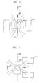
- FIG. 9is a perspective view of a 2 DOF embodiment in which the mass elements are constrained to one-dimensional rotational ballistic motion.
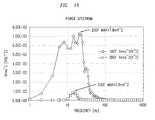
- FIG. 10shows comparative measured power spectra of a 2 DOF experimental prototype similar to FIG. 1 and a single-DOF system with the same total mass, volume and acceleration level.
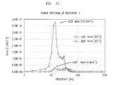
- FIG. 11shows comparative measured power spectra of a 2 DOF experimental prototype similar to FIG. 5 and a comparable single-DOF arrangement.
- FIG. 1An embodiment of the invention is shown schematically in FIG. 1 .
- a mass element 10 of higher mass M 1 and a mass element 20 of lower mass m 2move ballistically along a vertical path to which they are constrained by low-friction guiding rod 30 .
- ballisticthat except for the path constraints and except for collisions, the motion of the body is dominated by its own momentum, gravity, and pseudogravity, but is not dominated by friction and applied forces. (Of course some friction will be present, and forces, e.g. electromagnetic forces, exchanged with an energy transducer may also affect the ballistic motion to some extent.)
- the mass elements and guiding rodare contained within a housing 40 to which the guiding rod is fixed.
- the housingis advantageously evacuated to reduce losses from air resistance.
- Highly restitutive spring elements 50 and 60affixed respectively to the bottoms (as seen in the figure) of M 1 and m 2 act to prevent inelastic energy loss in collisions between M 1 and the housing, and between M 1 and m 2 .
- highly restitutive spring element 70serves as a stop and to prevent inelastic energy loss in collisions between m 2 and the housing.
- solenoidal coil 80which in the shown embodiment is coaxial with guiding rod 30 , which is concentric with the displacement axis of the mass elements.
- Mass element 20(referred to hereinafter as “m 2 ” except where there is a possibility of confusion) is wholly or partly composed of a permanent magnet.
- the magnetic field of m 2is conformed so that when m 2 is set in motion, coil 80 is threaded by a time-varying magnetic flux.
- an output voltage V outis produced by electromagnetic induction.
- the output voltageis typically applied across a load resistance R L , not shown in the figure.
- the housingis in contact with an external source of mechanical disturbance 90 , whose time-dependent vertical (as seen in the figure) acceleration is here denoted ⁇ .
- ⁇time-dependent vertical acceleration
- the mass of the energy harvesterwill be too small to affect the driving acceleration ⁇ , which may be due, for example, to vibrations of a large machine or structure, or to displacements in a body of water.
- the non-inertial acceleration ⁇ umlaut over (z) ⁇ imparted to the mass elements relative to the housingmay in general be assumed equal to ⁇ .
- coil 80An alternative to coil 80 is an element comprising a magnetostrictive material such as Terefenol D, combined with an element comprising an electroactive material.
- the variable magnetic fieldcauses a rotation of magnetization in the magnetostrictive material and the rotating magnetization generates a stress in magnetostrictive material.
- the stressis transmitted to the electroactive material, which responds by generating voltage.
- the respective elements 10 and 20are dissimilar in mass, with the mass M 1 of element 10 being greater than the mass m 2 of element 20 .
- element 10will hereinafter be referred to as “M 2 ” except where there is a possibility of confusion.
- the generated electrical powerwill equal the mechanical power removed from the system by the electrically induced damping d e irrespective of the conversion technique deployed.
- Nthe number of windings of the solenoid
- Athe cross-sectional area
- Bthe perpendicular magnetic field applied over the area A.
- V oc (t)⁇ Bl ⁇ where l is the length of the solenoid wire.
- the electrical damping coefficient d edepends on the electrical load and the electromagnetic coupling between the coil and the magnetic field. A very high electrical damping will cause a very low velocity, and by contrast a very small electrical coupling will produce too small an output voltage. All these effects, in addition to the geometrical constraints, should be considered in the design of the harvester in order to find the optimal configuration.
- M 1 and m 2may be of equal mass.
- both M 1 and m 2may be made to interact with transducers, for example by providing both mass elements with magnets and installing a respective coil to interact with each mass element.
- there may be further mass elements beyond m 2arranged to receive some of the initial kinetic energy of M 1 through a chain of collisions. Some or all of these further mass elements may interact with transducers to produce output power.
- FIG. 1illustrates one embodiment of an energy harvester having two degrees of freedom.
- a mass elementmay be mounted at the end of a deflectable cantilevered beam, such that it is constrained to move in an arc having a single rotational axis.
- Such an arrangementalso has a single degree of freedom per mass element constrained in that fashion.
- collisional energy transfertakes place through direct impact, without the mediation of a spring or the like.
- one or both of M 1 and m 2are anchored to the housing by a spring or the like.
- FIG. 2shows schematically an arrangement for a three DOF device in which element 110 of largest mass M 1 is anchored to the housing by spring 160 , and element 120 of intermediate mass m 2 is situated between element 110 and element 130 of smallest mass m 3 .
- the element of smallest mass m 3includes the permanent magnet that interacts with coil 80 .
- spring 70 affixed to the housingacts as a resilient stop to the motion of element 130 , and collisions between the mass elements are mediated by spring 140 attached to the bottom of element 120 , and by spring 150 attached to the bottom of element 130 .
- FIG. 3shows schematically another arrangement for a three DOF device in which mass elements 160 and 180 , of respective (and possibly equal) masses M 1 and M 2 are respectively anchored to the bottom and top of the housing by springs 210 and 220 .
- Element 170which has a mass m 3 smaller than both M 1 and M 2 is situated between elements 160 and 180 .
- Element 170includes the magnet for interacting with coil 80 .
- Springs 190 and 200attached respectively to the bottom and top of element 170 , mediate the collisions between element 170 and the other two mass elements.
- the displacement axis of the moveable bodies when in useis vertically oriented as shown in FIG. 1 , in other embodiments the orientation is horizontal.
- transducermay employ a different type of transducer.
- known transduction mechanisms useful in this contextfall into four categories: piezoelectric, electrostatic, electromagnetic and magnetostrictive.
- Piezoelectric effectsoccur in polarized materials such as barium titanate, lead zirconate titanate, and zinc oxide.
- polarized materialssuch as barium titanate, lead zirconate titanate, and zinc oxide.
- the dipole alignmentcreates an electric voltage between opposite faces (parallel field d 33 ) or transversal sides (perpendicular field d 31 ).
- the electrostatic methodutilizes a variable capacitor subjected to a mechanical stress that varies its dielectric gap length. In this way, an opposing electrostatic force is produced in order to maintain the previous equilibrium position, causing an additional voltage to be produced across the plates.
- the magnetostrictive methodis another type of electromagnetic conversion.
- a stress applied to a polarized ferromagnetic materialsuch as Terefenol (chemical formula Tb x Dy 1-x Fe 2 ) produces a variable magnetic field that in turn induces a current in an adjacent conductive coil.
- magnetically induced stress in the magnetostrictive materialis transmitted to an electroactive material that responds by generating a voltage.
- transduction methods listed abovehas certain advantages and certain drawbacks that make it more suitable for some applications and device sizes, and less suitable for others. Those skilled in the art will appreciate these various advantages and drawbacks and will be able to make appropriate choices of transduction technology to suit particular applications and device sizes.
- piezoelectric transducersreadily provide suitable output voltages and are well adapted for miniaturization, e.g. in MEMS applications.
- the electromechanical coupling coefficients for piezoelectric thin filmsare relatively small, and relatively large load impedances are typically required for the piezoelectric transducer to reach it optimum working point.
- Variable capacitorsare well suited for MEMS applications, but they have relatively low power density, and they need to be charged to a reference voltage by an external electrical source such as a battery.
- Electromagnetic transducersare especially well suited for operation at relatively low frequencies in devices of medium size to drive loads of relatively low impedance. Bandwidth of the frequency response tends to decrease with increasing load.
- an exemplary range for “low” mechanical frequenciesis 10-100 Hz
- a devicemay be considered to be of “medium” size if its maximum spatial dimension is 1-10 cm
- an exemplary range for “low” impedancesis 1-1000 ohms.
- Electromagnetic transducersare relatively expensive to integrate in microsystems because micromagnets are complex to manufacture, and relatively large mass displacements are required. Moreover, typical output voltages are relatively low, and circuitry for voltage regulation and energy storage may add further inefficiencies. Despite these drawbacks, however, electromagnetic generators at the centimeter scale have exhibited greater power densities than piezoelectric generators, and show promise even at smaller scales.
- the electromagnetic transducer as shown, e.g., in FIG. 1can be operated without direct physical contact, whereas a mechanical stress must be applied to transducers of the other kinds listed above.
- One arrangement for applying mechanical stressmay be achieved, for example, by situating the transducer between m 2 and the housing, as seen, e.g., in FIG. 1 . That is, the transducer may be mounted on the top (as seen in the figure) of m 2 , or on the inner face of the housing, or it may be interposed between the housing and m 2 by placing it, e.g., between a pair of springs or other resilient elements.
- a flexural stressmay be applied to, e.g., a piezoelectric transducer.
- FIG. 4shows schematically an arrangement for a two DOF device employing mass element 230 of larger mass M 1 and mass element 240 of smaller mass m 2 , mounted at the ends of respective cantilevered beams 250 and 260 . Each of the beams is supported at the other end by a fixed anchor to wall 270 of the housing.
- Beams 250 and 260may be composed of piezoelectric material, or they may include piezoelectric material, exemplarily as a thin layer on the upper or lower beam surface.
- each of beams 250 , 260comprises a flexural steel plate on which bimorph piezoelectric layers have been deposited.
- the piezoelectric layersproduce voltage when they are stressed along the transversal ( ⁇ 31 ) or perpendicular ( ⁇ 33 ) direction. Piezoelectrically generated voltage is conducted to output terminals 290 by electrical lead wires 280 .
- collisional energy transfertakes place by direct impact between the mass elements, which are for that purpose advantageously composed of, or encased in, a highly restitutive material.
- the collisionsmay be mediated by springs, magnetic cushions, or the like.
- FIG. 5shows another embodiment of the invention, in which mass element 300 , having larger mass M 1 , contains a cavity bridged by the magnetic field from an array of permanent magnets 310 .
- Smaller mass element 320having mass m 2 , has a range of one-dimensional ballistic motion within the cavity, constrained by guide rods 330 .
- Spring (or other resilient cushion) elements 340 , 350are affixed respectively to the top and bottom of the cavity (as seen in the figure) and serve as stops at the ends of the range of motion of element 320 .
- Element 300likewise has a range of one-dimensional ballistic motion, which is constrained by guide rods 330 and terminated by spring (or other resilient cushion) elements 360 , 370 , affixed respectively to the top 380 and bottom 390 (as seen in the figure) of the enclosure.
- Mass element 300advantageously comprises a high-Q high permeability material such as non-oriented grain silicon steel or laminated steel, or ferrite, carbonyl, or another material characterized by high magnetic permittivity and low eddy current losses.
- a high-Q high permeability materialsuch as non-oriented grain silicon steel or laminated steel, or ferrite, carbonyl, or another material characterized by high magnetic permittivity and low eddy current losses.
- the advantage of such materialsis that they enable mass element 300 to serve as a magnetic flux closure yoke, which defines a magnetic circuit with the permanent magnet array 310 . As a consequence, the magnetic flux lines are closed within the structure, and the magnetic energy is concentrated within the cavity.
- Mass element 320includes a conductive coil (not shown in the figure) advantageously oriented with its normal axis parallel to the magnetic field so as to maximize the (time-dependent) magnetic flux threading the coil.
- the voltage induced by relative motion between the moving coil and the fixed magnetic fieldis conducted to output terminals by electrical lead wires (not shown in the figure).
- One advantage of the arrangement depicted in FIG. 5is that the larger mass element 300 not only transfers momentum to the smaller mass element, but also implements a powerful permanent gap magnet.
- a second advantageis that the magnetic field is entirely included within the structure, thus minimizing interference with external ferromagnetic materials.
- the arrangement of FIG. 5is a velocity-multiplying arrangement having two DOF.
- the energy conversiontakes place due to relative motion between the lighter mass element and the magnet array, which constitutes part of the transduction means and in this arrangement is attached to the outer mass element.
- both the heavier mass element and the lighter mass elementhave a range of linear ballistic motion.
- at least the heavier mass element 300could instead be anchored by a spring or other resilient element, in which case its linear motion would be, e.g., harmonic instead of ballistic.
- the energy transducer of FIG. 5includes a coil that moves within a magnetic gap, with the magnetic field lines substantially perpendicular to the plane of the coil. In that arrangement, the magnetic field lines are also substantially perpendicular to the direction of motion of the coil.
- any number of moving mass elementscould be given a respective, corresponding electromagnetic transduction element.
- the use of more than one electromagnetic transduction elementmay improve both the bandwidth response of the energy harvester and its power density, i.e., its output power per unit volume.
- the largest moving mass elementmay operate both to transfer momentum to one or more smaller elements, and to directly activate a transduction element. Because the overall power spectrum of the energy harvester is the result of the superposition of all of its vibrational modes, the direct participation of the largest mass element in transduction may advantageously broaden the electrical power spectrum at low frequencies.
- springs or other elements that mediate collisions within the energy harvestermay themselves also serve as electromechanical transducers.
- a small piezoelectric bar or cantilevermay at least partially convert collision impulses into useful electricity.
- FIG. 5provides an example of a transversal magnetic field in a moving-coil arrangement.
- FIG. 6provides an example of a coaxial magnetic field in a moving-magnet arrangement, and
- FIG. 7provides an example of a transversal magnetic field in a moving-magnet arrangement.
- Each figureshows magnet 400 moving relative to coil 410 in direction 420 on guide rod 430 .
- the direction 440 of the magnetic field lines on the coil axisis also indicated in the figures.
- FIG. 8shows an embodiment in which the smaller mass element m 2 , indicated in the figure by reference numeral 500 , undergoes linear ballistic motion within the larger mass element M 1 , which is indicated in the figure by reference numeral 510 .
- Mass element 500undergoes linear ballistic motion within housing 520 .
- Mass element 500includes a pair of magnets 530 , 535 , having oppositely-directed horizontal flux (in the figure view) and separated by spacer 540 .
- the mass elementsare constrained to linear motion by low-friction shaft or guide 550 . Collisions between mass element 510 and the housing and between the respective mass elements 500 , 510 are mediated by springs 560 .
- the interior of the housingis advantageously evacuated to reduce air resistance.
- the elements 580are electroactive layers. Stacked between the electroactive layers are magnetostrictive layers 570 . Layers 570 and 580 are included in mass element 510 .
- electroactive layersIn operation, as explained above, reversals of the flux direction due to the motion of magnet array 530 , 535 cause dimensional changes in the magnetostrictive layers that exert stress on the adjacent electroactive layers. As a consequence, the electroactive layers produce a voltage, which may be directed to output voltage terminals as shown in the figure.
- the respective electroactive layers materialcan be connected in a parallel or a series configuration, depending on whether is preferred to sum the individually output currents or voltages, respectively.
- the elements 580are solenoidal coils in which voltage is induced by the magnetic flux reversals, and the elements 570 are inert spacers.
- FIG. 9shows an embodiment in which the larger mass element M 1 , indicated in the figure by reference numeral 600 , includes a pair of radially extending wings 610 , 615 subtending a fixed angle of, e.g., 135 degrees and rotating as a unit on low-friction spindle 620 between stops 630 , 635 within housing 640 .
- the stopsmay have adjustable positions to define a variable range of rotational motion.
- the smaller mass element m 2includes a single, radially extending wing that rotates on spindle 620 within a range of motion defined by wings 610 , 615 .
- the outer end of mass element 660includes a pair of magnets 650 having opposite, radially directed magnetic flux. Collisions between mass element 600 and the stops, and between the respective mass elements, are mediated by springs 670 .
- the torsional motion of the bodiesmay also be ballistic, in the sense that except for the path constraints and except for collisions, the motion of each body is dominated by its own momentum, gravity, and pseudogravity, but is not dominated by friction and applied forces.
- the elements 680are magnetostrictive layers stacked with intervening electroactive layers 690 .
- reversals in the flux direction experienced by the magnetostrictive layers due to the motion of mass element 660cause the electroactive layers to produce a voltage, which may be summed and directed to output voltage terminals, as shown in FIG. 9 .
- the elements 690are solenoidal coils in which voltage is induced by the magnetic flux reversals, and the elements 680 are inert spacers.
- FIG. 9shows the device being excited by externally applied linear vibrations ( ⁇ ), it should be noted that the same device configuration may also be effectively excited by angular vibrations.
- PSDpower spectral density
- the lower curveis the PSD of the output voltage across the same load, from a single spring-mass-damper oscillator of the same total inertial mass driven by white Gaussian noise vibration.
- FIG. 10By giving a white Gaussian noise excitation up to 1.6 Khz, an interesting broadband response is illustrated in FIG. 10 , mostly at low frequency in the range 6-13 Hz. This shows that the output voltage is almost constant over a frequency band 5 times wider than is typical for a single-DOF system. The total power calculated as the integral of the PSD curve is increased by up to eight times relative to the resonant configuration.
- the sliding coil with its support(smaller mass) is free to move along the linear guides inside the gap magnet which acts as the heavier mass.
- the heavier mass M 1which measured 420 g, was free to slide along the linear guides, bouncing on the housing base and shaking the smaller mass m 2 within itself.
- the smaller mass m 2measured 5.2 g, giving a relatively high value of 80.7 for the ratio of the respective masses.
- High quality factor elementssuch as wave weakly magnetic steel (or copper-berillium) springs may be used as mitigators to produce high restitution coefficient collisions.
- high quality factor piezoelectric cantileversmay be used to gather more energy from the impacts.
- Both the coil and the gap magnetplay the role of movers. If they move relatively out-of-phase (180 degrees), the relative velocity of the coil referring to the magnet is doubled with respect to a common stator-mover design.
- a magnetic field of 0.85 Teslawas produced by commercial N42 neodymium permanent magnet with rectangular shape inside a 5 mm gap.
- the fieldcan be increased up to, e.g., one Tesla by using the off-the-shelf N52 category of permanent magnet.
- Air core coils instead of iron corewere chosen to avoid eddy currents losses and excessively strong nonlinear electromagnetic forces which could impede the velocity amplification of the lighter mass.
- FIG. 11shows the averaged power spectrum (PSD) of the output voltage of the velocity amplified double-DOF prototype, compared with a single-DOF arrangement.
- the output voltageis measured across a load R L of 100.2 ohm, there is a total inertial mass of 450 g, and the vibrational input is Gaussian random noise of 6.5 m/s 2 maximum acceleration.
- the figureshows an improvement by a factor of five to ten in comparison with common 1-DOF oscillating systems.
Landscapes
- Engineering & Computer Science (AREA)
- Power Engineering (AREA)
- Apparatuses For Generation Of Mechanical Vibrations (AREA)
Abstract
Description
where m and M are respectively the small and large masses of initial velocities v and V, and C is the restitution coefficient.
Claims (20)
Priority Applications (1)
| Application Number | Priority Date | Filing Date | Title |
|---|---|---|---|
| US12/586,937US8350394B2 (en) | 2009-09-30 | 2009-09-30 | Energy harvester apparatus having improved efficiency |
Applications Claiming Priority (1)
| Application Number | Priority Date | Filing Date | Title |
|---|---|---|---|
| US12/586,937US8350394B2 (en) | 2009-09-30 | 2009-09-30 | Energy harvester apparatus having improved efficiency |
Publications (2)
| Publication Number | Publication Date |
|---|---|
| US20110074162A1 US20110074162A1 (en) | 2011-03-31 |
| US8350394B2true US8350394B2 (en) | 2013-01-08 |
Family
ID=43779455
Family Applications (1)
| Application Number | Title | Priority Date | Filing Date |
|---|---|---|---|
| US12/586,937Active2031-03-02US8350394B2 (en) | 2009-09-30 | 2009-09-30 | Energy harvester apparatus having improved efficiency |
Country Status (1)
| Country | Link |
|---|---|
| US (1) | US8350394B2 (en) |
Cited By (22)
| Publication number | Priority date | Publication date | Assignee | Title |
|---|---|---|---|---|
| US20120248774A1 (en)* | 2011-03-28 | 2012-10-04 | Stewart David B | Pitch driven wave energy converter devices and systems |
| US20130020806A1 (en)* | 2011-07-18 | 2013-01-24 | Sean Nean Hsu | Fluid Flow Generator |
| US20140060367A1 (en)* | 2012-03-12 | 2014-03-06 | Omnitek Partners Llc | Gravity dropped small weapon electronic safe arm fuze and energy harvesting device for power generation onboard gravity dropped weapons |
| US20140133930A1 (en)* | 2011-07-19 | 2014-05-15 | Mauser-Werker Oberndorf Maschinenbau GmbH | Readjustment System |
| US20140284938A1 (en)* | 2011-10-26 | 2014-09-25 | Yuliang Xu | Gravitational energy conversion device and application thereof |
| US8866317B2 (en) | 2012-01-17 | 2014-10-21 | Schlumberger Technology Corporation | Broadband vibrational energy harvesting |
| EP2882092A1 (en) | 2013-12-05 | 2015-06-10 | Alcatel Lucent | An energy harvester |
| US20150280616A1 (en)* | 2013-05-17 | 2015-10-01 | Panasonic Intellectual Property Management Co., Ltd. | Power-generating vibration sensor, and tire and electrical device using the same |
| US9206672B2 (en) | 2013-03-15 | 2015-12-08 | Fastcap Systems Corporation | Inertial energy generator for supplying power to a downhole tool |
| US20160164390A1 (en)* | 2013-07-24 | 2016-06-09 | Mitsumi Electric Co., Ltd | Power generator, power generator set and power generation system |
| US9541058B2 (en) | 2012-12-12 | 2017-01-10 | Repsol, S.A. | Energy converters and energy conversion systems |
| US20170179791A1 (en)* | 2014-07-17 | 2017-06-22 | Omnitek Partners Llc | Methods for Generating Power From Miniature Electrical Generators and Power Sources |
| US10033249B2 (en)* | 2013-10-14 | 2018-07-24 | Sunrising Eco-Friendly Tech. Co., Ltd. | Mobile induction and power-generation device |
| US10082128B2 (en)* | 2012-06-05 | 2018-09-25 | Ddnt Consultants Australia Pty Ltd. | Wave power generation system and method |
| US20180355837A1 (en)* | 2017-06-08 | 2018-12-13 | P Tech, Llc | Systems and methods for energy harvest |
| US10190394B2 (en) | 2013-11-08 | 2019-01-29 | Halliburton Energy Services, Inc. | Energy harvesting from a downhole jar |
| US20200119619A1 (en)* | 2018-10-16 | 2020-04-16 | Thomas Nikita Krupenkin | Method and Apparatus For Mechanical Energy Harvesting Using Variable Inductance Magnetic Flux Switch |
| US10815961B2 (en)* | 2018-10-01 | 2020-10-27 | Abu Dhabi Polytechnic | Ocean wave power generator with artificially intelligent controller |
| US10958192B2 (en)* | 2015-10-05 | 2021-03-23 | Koninklijke Philips N.V. | Energy conversion system and method |
| US11539232B2 (en)* | 2018-03-30 | 2022-12-27 | Ordos Yuansheng Optoelectronics Co., Ltd. | Display device |
| US11637479B2 (en) | 2019-12-30 | 2023-04-25 | P Tech, Llc | Wave energy harvester |
| US20230283206A1 (en)* | 2022-03-01 | 2023-09-07 | Southwest Jiaotong University | Portable charging device with kinetic energy recovery |
Families Citing this family (40)
| Publication number | Priority date | Publication date | Assignee | Title |
|---|---|---|---|---|
| US8030786B2 (en)* | 2008-08-22 | 2011-10-04 | Willowview Systems, Inc. | System for generating electrical energy from ambient energy |
| KR20110026644A (en)* | 2009-09-08 | 2011-03-16 | 한국전자통신연구원 | Piezoelectric energy harvesting device and its manufacturing method |
| US20120217759A1 (en)* | 2011-02-25 | 2012-08-30 | Boyd Joe J | Batches of energy |
| DE102011007397B4 (en)* | 2011-04-14 | 2016-03-10 | Hahn-Schickard-Gesellschaft für angewandte Forschung e.V. | Device for converting kinetic energy into electrical energy |
| US8736148B2 (en)* | 2011-05-04 | 2014-05-27 | James Douglass Penn | Multiple degree of freedom actuator and method |
| FR2975842B1 (en)* | 2011-05-24 | 2013-05-17 | Eurocopter France | DEVICE FOR ELECTRICALLY SUPPLYING AT LEAST ONE EQUIPMENT OF A ROTOR ROTOR OF AN AIRCRAFT AND AN AIRCRAFT |
| US8816540B2 (en)* | 2011-07-22 | 2014-08-26 | Northeastern University | High energy density vibration energy harvesting device with high-mu material |
| WO2013082578A1 (en)* | 2011-12-03 | 2013-06-06 | Thomas Krupenkin | Method and apparatus for mechanical energy harvesting using combined magnetic and microfluidic energy generation |
| US8907506B2 (en)* | 2012-02-01 | 2014-12-09 | Virginia Tech Intellectual Properties, Inc. | Multimodal vibration harvester combining inductive and magnetostrictive mechanisms |
| DE102012002869B4 (en)* | 2012-02-13 | 2016-02-18 | Jorge Luis Sanchez Vargas | Magnetic working means for a generator and / or motor station of a system for the need-based storage and / or delivery of electrical energy |
| DE102012002867B4 (en)* | 2012-02-13 | 2016-04-21 | Jorge Luis Sanchez Vargas | Generator and / or motor station for a system for on-demand storage and / or delivery of electrical energy |
| EP2856628B1 (en) | 2012-05-25 | 2016-05-04 | Cambridge Enterprise Limited | Energy-harvesting apparatus and method |
| EP2698609B1 (en)* | 2012-08-13 | 2021-03-03 | Alcatel Lucent | Wireless sensing device and method |
| EP2885869A4 (en)* | 2012-08-17 | 2016-07-20 | Thomas Nikita Krupenkin | APPARATUS FOR RECOVERING MECHANICAL ENERGY INCORPORATED IN SHOE USING MODULAR ELEMENTS |
| JP5998879B2 (en)* | 2012-11-28 | 2016-09-28 | 富士通株式会社 | Power generator |
| WO2014091005A1 (en)* | 2012-12-14 | 2014-06-19 | Meggitt A/S | Generator unit for energy harvesting with a single force input point |
| US9913321B2 (en)* | 2013-01-25 | 2018-03-06 | Energyield, Llc | Energy harvesting container |
| JP2015532472A (en)* | 2013-08-09 | 2015-11-09 | アルカテル−ルーセント | Wireless sensing device and method |
| US20150162524A1 (en)* | 2013-11-05 | 2015-06-11 | Oscilla Power, Inc. | Secondary flux path for magnetostrictive circuits |
| ITTO20131040A1 (en)* | 2013-12-18 | 2015-06-19 | Indesit Co Spa | MACHINE WASHING MACHINE OR WASHING MACHINE INCLUDING AN ELECTRIC CURRENT GENERATOR |
| US9537368B2 (en)* | 2014-01-30 | 2017-01-03 | Farouk Dakhil | Magnetic power generator for hybrid vehicle and/or electric power plant |
| WO2015183281A1 (en)* | 2014-05-29 | 2015-12-03 | Microgen Systems, Inc. | Internal vibration impulsed broadband excitation energy harvester systems and methods |
| EP3245156B1 (en) | 2015-01-16 | 2021-09-08 | Université Gustave Eiffel | Miniature kinetic energy harvester for generating electrical energy from mechanical vibrations |
| LT6330B (en) | 2015-01-29 | 2016-11-10 | Kauno technologijos universitetas | Piezoelectric generator converting low frequency vibration into electrical energy. |
| US9267824B1 (en)* | 2015-02-02 | 2016-02-23 | Goodrich Corporation | Sensor systems |
| US10378934B2 (en)* | 2015-02-02 | 2019-08-13 | Goodrich Corporation | Sensor systems |
| DE102015102384A1 (en)* | 2015-02-19 | 2016-08-25 | Afag Holding Ag | Sensor device for providing at least one operating parameter of a vibrating conveyor and vibratory conveyor |
| FR3056854B1 (en)* | 2016-09-27 | 2019-09-20 | Enerbee | GENERATOR FOR TRANSFORMING MOVEMENT OF TRANSLATION OF A BODY IN ACCUMULATION OF ELECTRICAL LOADS |
| KR101891888B1 (en)* | 2016-09-28 | 2018-08-24 | 호서대학교 산학협력단 | Generating device |
| US10793427B2 (en) | 2017-04-04 | 2020-10-06 | Kionix, Inc. | Eutectic bonding with AlGe |
| CN106849599B (en)* | 2017-04-23 | 2023-04-07 | 吉林大学 | Electromagnetic friction piezoelectric combined type energy collector |
| CN107859606B (en)* | 2017-12-01 | 2019-05-24 | 麦国毅 | A multi-stage waterproof piezoelectric environmental mechanical energy cycle conversion environmental protection device |
| EP3525329B1 (en)* | 2018-02-12 | 2023-01-25 | Nokia Technologies Oy | Vibration energy harvester |
| CN108462355A (en)* | 2018-03-01 | 2018-08-28 | 中南大学 | Electromagnetic vibration energy collector for Bridges on Urban Rail Transit health monitoring |
| JP6887965B2 (en)* | 2018-03-06 | 2021-06-16 | アルカテル・ルーセント | Wireless sensing devices and methods |
| US11313877B2 (en)* | 2018-06-19 | 2022-04-26 | Kionix, Inc. | Near-zero power wakeup electro-mechanical system |
| GB201909277D0 (en)* | 2019-06-27 | 2019-08-14 | Univ Limerick | Vibrational energy harvester |
| CN111564946B (en)* | 2020-06-15 | 2022-02-25 | 河南工业大学 | Low-frequency broadband electromagnetic-piezoelectric-friction combined vibration energy collector |
| CN113090483B (en)* | 2021-04-02 | 2022-08-02 | 山东理工大学 | Airfoil surface pit local aeroelastic vibration piezoelectric energy harvester |
| US12381417B2 (en)* | 2022-07-05 | 2025-08-05 | Raul Eduardo Rivas-Sanz | Nano-scale electromagnetic inductance cells, arrays formed thereof, and uses thereof |
Citations (67)
| Publication number | Priority date | Publication date | Assignee | Title |
|---|---|---|---|---|
| US3696251A (en)* | 1969-06-30 | 1972-10-03 | Univ North Wales | Method of generating electricity and electrical generator |
| US4423334A (en)* | 1979-09-28 | 1983-12-27 | Jacobi Edgar F | Wave motion electric generator |
| US4851704A (en)* | 1988-10-17 | 1989-07-25 | Rubi Ernest P | Wave action electricity generation system and method |
| US5144847A (en)* | 1988-03-24 | 1992-09-08 | Johann Zach | Pressure or force measuring device |
| US5347186A (en)* | 1992-05-26 | 1994-09-13 | Mcq Associates, Inc. | Linear motion electric power generator |
| US5460099A (en)* | 1993-03-30 | 1995-10-24 | Hiroshi Matsuhisa | Dynamic vibration absorber for pendulum type structure |
| US5541497A (en)* | 1992-04-17 | 1996-07-30 | Shikoku Denryoku Kabushiki Kaisha | Power storing apparatus |
| US5552657A (en)* | 1995-02-14 | 1996-09-03 | Ocean Power Technologies, Inc. | Generation of electrical energy by weighted, resilient piezoelectric elements |
| US5578877A (en)* | 1994-06-13 | 1996-11-26 | General Electric Company | Apparatus for converting vibratory motion to electrical energy |
| US5818132A (en) | 1997-01-13 | 1998-10-06 | Konotchick; John A. | Linear motion electric power generator |
| US5975714A (en)* | 1997-06-03 | 1999-11-02 | Applied Innovative Technologies, Incorporated | Renewable energy flashlight |
| US6128385A (en)* | 1997-09-30 | 2000-10-03 | Lucent Technologies, Inc. | Impact-tolerant mounting of acoustic components |
| US6220719B1 (en)* | 1998-02-11 | 2001-04-24 | Applied Innovative Technologies, Inc. | Renewable energy flashlight |
| US20020172060A1 (en)* | 2001-04-20 | 2002-11-21 | Seiki Epson Corporation | Apparatus for converting vibration energy into electric power |
| US6539803B2 (en)* | 2000-07-07 | 2003-04-01 | Murata Manufacturing Co., Ltd. | External force measuring device |
| US6700248B2 (en)* | 2001-05-09 | 2004-03-02 | Harmonic Drive, Inc. | Non-linear magnetic motion converter |
| US20040075363A1 (en) | 2002-10-21 | 2004-04-22 | Malkin Matthew C. | Multi-frequency piezoelectric energy harvester |
| US6729744B2 (en)* | 2002-03-29 | 2004-05-04 | Pat Y. Mah | Faraday flashlight |
| US6768230B2 (en) | 2002-02-19 | 2004-07-27 | Rockwell Scientific Licensing, Llc | Multiple magnet transducer |
| US20040183306A1 (en)* | 2003-03-17 | 2004-09-23 | Rome Lawrence C | Backpack for harvesting electrical energy during walking and for minimizing shoulder strain |
| US6798090B2 (en)* | 2002-04-18 | 2004-09-28 | Rockwell Scientific Licensing, Llc | Electrical power generation by coupled magnets |
| US6809427B2 (en)* | 2002-02-19 | 2004-10-26 | Rockwell Scientific Licensing, Llc | Electrical generator with ferrofluid bearings |
| US6812598B2 (en)* | 2002-02-19 | 2004-11-02 | Rockwell Scientific Licensing, Llc | Multiple magnet transducer with differential magnetic strengths |
| US20040222638A1 (en)* | 2003-05-08 | 2004-11-11 | Vladimir Bednyak | Apparatus and method for providing electrical energy generated from motion to an electrically powered device |
| US20040222637A1 (en)* | 2003-05-08 | 2004-11-11 | Vladimir Bednyak | Apparatus and method for generating electrical energy from motion |
| US6893141B2 (en)* | 2002-03-29 | 2005-05-17 | Pat Y. Mah | Faraday flashlight |
| US20050134149A1 (en) | 2003-07-11 | 2005-06-23 | Deng Ken K. | Piezoelectric vibration energy harvesting device |
| US6984902B1 (en) | 2003-02-03 | 2006-01-10 | Ferro Solutions, Inc. | High efficiency vibration energy harvester |
| US7148583B1 (en)* | 2005-09-05 | 2006-12-12 | Jeng-Jye Shau | Electrical power generators |
| US7239038B1 (en)* | 2005-12-16 | 2007-07-03 | Harris Corporation | Apparatus for electrical signal generation based upon movement and associated methods |
| US7245062B2 (en)* | 2002-05-14 | 2007-07-17 | Enocean Gmbh | Device for converting mechanical energy into electrical energy |
| US20070188153A1 (en)* | 2006-02-13 | 2007-08-16 | Commissariat A L'energie Atomique | Energy conversion system with variable airgap distance and energy recovery method |
| US20070210580A1 (en)* | 2006-03-08 | 2007-09-13 | Perpetuum Ltd. | Electromechanical generator for, and method of, converting mechanical vibrational energy into electrical energy |
| US20070220950A1 (en)* | 2006-03-17 | 2007-09-27 | Lucent Technologies, Inc. | Shock apparatus |
| US20070220949A1 (en)* | 2006-03-17 | 2007-09-27 | Suresh Goyal | Rotational and linear shock apparatus |
| US7288860B2 (en)* | 2002-02-19 | 2007-10-30 | Teledyne Licensing, Inc. | Magnetic transducer with ferrofluid end bearings |
| US20070257491A1 (en)* | 2006-05-05 | 2007-11-08 | Sri International | Wave powered generation |
| US20070257490A1 (en)* | 2006-05-05 | 2007-11-08 | Sri International | Wave powered generation using electroactive polymers |
| US20070266764A1 (en)* | 2006-05-16 | 2007-11-22 | Lucent Technologies, Inc. | Shock and launch apparatus |
| US20080074083A1 (en)* | 2006-06-26 | 2008-03-27 | Yarger Eric J | System and method for storing energy |
| US20080164702A1 (en)* | 2007-01-08 | 2008-07-10 | Veryst Engineering Llc | Method and Apparatus for Energy Harvesting Using Rotational Energy Storage and Release |
| US20080174120A1 (en)* | 2007-01-19 | 2008-07-24 | Motionetics, Inc. | System for generating electrical energy from ambient motion |
| US20080217926A1 (en)* | 2007-03-07 | 2008-09-11 | Aaron Patrick Lemieux | Electrical Energy generator |
| US7464800B2 (en)* | 2004-03-16 | 2008-12-16 | George Nerubenko | Torisonal vibration damper of a rotating shaft |
| US7498681B1 (en)* | 2007-03-21 | 2009-03-03 | Sandia Corporation | Mechanical vibration to electrical energy converter |
| US7501726B1 (en)* | 2004-07-28 | 2009-03-10 | The United States Of America As Represented By The Secretary Of The Navy | Micro-electro-mechanical system (MEMS) and apparatus for generating power responsive to mechanical vibration |
| US7525203B1 (en)* | 2005-08-11 | 2009-04-28 | Jeffrey Racho | Back-up electric power generator for electronic components attached to automatic firearms |
| US20090218824A1 (en)* | 2005-10-04 | 2009-09-03 | Perpetuum Ltd. | Electromechanical Generator for Converting Mechanical Vibrational Energy Into Electrical Energy |
| US20100045119A1 (en)* | 2008-08-22 | 2010-02-25 | Ronald Scott Jackson | System for generating electrical energy from ambient energy |
| US7703562B2 (en)* | 2007-05-25 | 2010-04-27 | Toyota Motor Engineering & Manufacturing North America, Inc. | Energy efficient robotic system |
| US20100187835A1 (en)* | 2007-06-29 | 2010-07-29 | Stichting Imec Nederland | Electromagnetic Energy Scavenger Based on Moving Permanent Magnets |
| US20100194117A1 (en)* | 2009-02-05 | 2010-08-05 | Schlumberger Technology Corporation | Electromagnetic device having compact flux paths for harvesting energy from vibrations |
| US20100236440A1 (en)* | 2009-03-19 | 2010-09-23 | Omnitek Partners Llc | Methods and Apparatus For Mechanical Reserve Power Sources For Gun-Fired Munitions, Mortars, and Gravity Dropped Weapons |
| US20100283264A1 (en)* | 2006-06-06 | 2010-11-11 | Omnitek Partners Llc | Impact Powered Devices |
| US7851932B2 (en)* | 2007-03-29 | 2010-12-14 | Lightning Packs, Llc | Backpack based system for human electricity generation and use when off the electric grid |
| US20110012369A1 (en)* | 2009-07-17 | 2011-01-20 | Kurt Paul Grossman | Submerged power generator |
| US20110109102A1 (en)* | 2009-10-29 | 2011-05-12 | Mccoy John J | Meta-material vibration energy harvester |
| US20110193350A1 (en)* | 2008-06-19 | 2011-08-11 | Omnitek Partners Llc | Electrical Generators For Low-Frequency and Time-Varying Rocking and Rotary Motions |
| US20110215590A1 (en)* | 2007-09-18 | 2011-09-08 | University Of Florida Research Foundation, Inc. | Dual-Mode Piezoelectric/Magnetic Vibrational Energy Harvester |
| US8022563B2 (en)* | 2008-03-07 | 2011-09-20 | Tremont Electric Incorporated | Wave energy converter |
| US8067849B2 (en)* | 2005-12-01 | 2011-11-29 | Ocean Power Technologies, Inc. | Wave energy converter with internal mass on spring oscillator |
| US8072122B2 (en)* | 2011-05-03 | 2011-12-06 | Hong Kong Applied Science and Technology Research Institute Company Limited | Self-powered impulse detection system with piezoelectric energy harvester |
| US20110316290A1 (en)* | 2009-03-13 | 2011-12-29 | Kabushiki Kaisha Bridgestone | Intra-tire power generating apparatus |
| US20120104877A1 (en)* | 2010-11-02 | 2012-05-03 | Blake L. Isaacs | Portable Linear Generator |
| US20120104874A1 (en)* | 2010-10-28 | 2012-05-03 | Hwang Yeong-Maw | Vibrating-type electromagnetic generator |
| US20120161583A1 (en)* | 2010-12-23 | 2012-06-28 | Korea Electronics Technology Institute | Piezoelectric power generator for feeding emergency power |
| US8222754B1 (en)* | 2008-05-28 | 2012-07-17 | Arjae Spectral Enterprises Ltd. | Vibration-based power generator |
- 2009
- 2009-09-30USUS12/586,937patent/US8350394B2/enactiveActive
Patent Citations (100)
| Publication number | Priority date | Publication date | Assignee | Title |
|---|---|---|---|---|
| US3696251A (en)* | 1969-06-30 | 1972-10-03 | Univ North Wales | Method of generating electricity and electrical generator |
| US4423334A (en)* | 1979-09-28 | 1983-12-27 | Jacobi Edgar F | Wave motion electric generator |
| US5144847A (en)* | 1988-03-24 | 1992-09-08 | Johann Zach | Pressure or force measuring device |
| US4851704A (en)* | 1988-10-17 | 1989-07-25 | Rubi Ernest P | Wave action electricity generation system and method |
| US5541497A (en)* | 1992-04-17 | 1996-07-30 | Shikoku Denryoku Kabushiki Kaisha | Power storing apparatus |
| US5347186A (en)* | 1992-05-26 | 1994-09-13 | Mcq Associates, Inc. | Linear motion electric power generator |
| US5460099A (en)* | 1993-03-30 | 1995-10-24 | Hiroshi Matsuhisa | Dynamic vibration absorber for pendulum type structure |
| US5578877A (en)* | 1994-06-13 | 1996-11-26 | General Electric Company | Apparatus for converting vibratory motion to electrical energy |
| US5552657A (en)* | 1995-02-14 | 1996-09-03 | Ocean Power Technologies, Inc. | Generation of electrical energy by weighted, resilient piezoelectric elements |
| US5818132A (en) | 1997-01-13 | 1998-10-06 | Konotchick; John A. | Linear motion electric power generator |
| US5975714A (en)* | 1997-06-03 | 1999-11-02 | Applied Innovative Technologies, Incorporated | Renewable energy flashlight |
| US6128385A (en)* | 1997-09-30 | 2000-10-03 | Lucent Technologies, Inc. | Impact-tolerant mounting of acoustic components |
| US6220719B1 (en)* | 1998-02-11 | 2001-04-24 | Applied Innovative Technologies, Inc. | Renewable energy flashlight |
| US6539803B2 (en)* | 2000-07-07 | 2003-04-01 | Murata Manufacturing Co., Ltd. | External force measuring device |
| US20020172060A1 (en)* | 2001-04-20 | 2002-11-21 | Seiki Epson Corporation | Apparatus for converting vibration energy into electric power |
| US7009315B2 (en)* | 2001-04-20 | 2006-03-07 | Seiko Epson Corporation | Apparatus for converting vibration energy into electric power |
| US6700248B2 (en)* | 2001-05-09 | 2004-03-02 | Harmonic Drive, Inc. | Non-linear magnetic motion converter |
| US6812598B2 (en)* | 2002-02-19 | 2004-11-02 | Rockwell Scientific Licensing, Llc | Multiple magnet transducer with differential magnetic strengths |
| USRE41626E1 (en)* | 2002-02-19 | 2010-09-07 | Teledyne Licensing, Llc | Multiple magnet transducer with differential magnetic strengths |
| US6768230B2 (en) | 2002-02-19 | 2004-07-27 | Rockwell Scientific Licensing, Llc | Multiple magnet transducer |
| US7288860B2 (en)* | 2002-02-19 | 2007-10-30 | Teledyne Licensing, Inc. | Magnetic transducer with ferrofluid end bearings |
| US6861772B2 (en)* | 2002-02-19 | 2005-03-01 | Rockwell Scientific Licensing, Llc | Multiple magnet system with different magnet properties |
| US6809427B2 (en)* | 2002-02-19 | 2004-10-26 | Rockwell Scientific Licensing, Llc | Electrical generator with ferrofluid bearings |
| US6812583B2 (en)* | 2002-02-19 | 2004-11-02 | Rockwell Scientific Licensing, Llc | Electrical generator with ferrofluid bearings |
| US6893141B2 (en)* | 2002-03-29 | 2005-05-17 | Pat Y. Mah | Faraday flashlight |
| US7229188B2 (en)* | 2002-03-29 | 2007-06-12 | Daka Research Inc. | Faraday flashlight |
| US6808288B2 (en)* | 2002-03-29 | 2004-10-26 | Pat Y. Mah | Faraday flashlight |
| US7431474B2 (en)* | 2002-03-29 | 2008-10-07 | Cricket Holdings Far East Ltd. | Faraday flashlight |
| US6729744B2 (en)* | 2002-03-29 | 2004-05-04 | Pat Y. Mah | Faraday flashlight |
| US6994450B2 (en)* | 2002-03-29 | 2006-02-07 | Daka Research Inc. (Br.Virg.Isl Corp.) Offshore Incorporations | Faraday flashlight |
| US6798090B2 (en)* | 2002-04-18 | 2004-09-28 | Rockwell Scientific Licensing, Llc | Electrical power generation by coupled magnets |
| US7245062B2 (en)* | 2002-05-14 | 2007-07-17 | Enocean Gmbh | Device for converting mechanical energy into electrical energy |
| US20040075363A1 (en) | 2002-10-21 | 2004-04-22 | Malkin Matthew C. | Multi-frequency piezoelectric energy harvester |
| US6984902B1 (en) | 2003-02-03 | 2006-01-10 | Ferro Solutions, Inc. | High efficiency vibration energy harvester |
| US20040183306A1 (en)* | 2003-03-17 | 2004-09-23 | Rome Lawrence C | Backpack for harvesting electrical energy during walking and for minimizing shoulder strain |
| US20060192386A1 (en)* | 2003-03-17 | 2006-08-31 | Rome Lawrence C | Backpack for harvesting electrical energy during walking and for minimizing shoulder strain |
| US7391123B2 (en)* | 2003-03-17 | 2008-06-24 | Lightning Packs Llc | Backpack for harvesting electrical energy during walking and for minimizing shoulder strain |
| US6982497B2 (en)* | 2003-03-17 | 2006-01-03 | Lightning Packs, Llc | Backpack for harvesting electrical energy during walking and for minimizing shoulder strain |
| US7105939B2 (en)* | 2003-05-08 | 2006-09-12 | Motion Charge, Inc. | Electrical generator having an oscillator containing a freely moving internal element to improve generator effectiveness |
| US20040222638A1 (en)* | 2003-05-08 | 2004-11-11 | Vladimir Bednyak | Apparatus and method for providing electrical energy generated from motion to an electrically powered device |
| US20040222637A1 (en)* | 2003-05-08 | 2004-11-11 | Vladimir Bednyak | Apparatus and method for generating electrical energy from motion |
| US20050134149A1 (en) | 2003-07-11 | 2005-06-23 | Deng Ken K. | Piezoelectric vibration energy harvesting device |
| US7464800B2 (en)* | 2004-03-16 | 2008-12-16 | George Nerubenko | Torisonal vibration damper of a rotating shaft |
| US7501726B1 (en)* | 2004-07-28 | 2009-03-10 | The United States Of America As Represented By The Secretary Of The Navy | Micro-electro-mechanical system (MEMS) and apparatus for generating power responsive to mechanical vibration |
| US20090167034A1 (en)* | 2004-07-28 | 2009-07-02 | Waters Richard L | Appartus for Generating Power Responsive to Mechanical Vibration |
| US7902698B1 (en)* | 2004-07-28 | 2011-03-08 | The United States Of America As Represented By The Secretary Of The Navy | Method of fabricating a micro-electro-mechanical apparatus for generating power responsive to mechanical vibration |
| US7525203B1 (en)* | 2005-08-11 | 2009-04-28 | Jeffrey Racho | Back-up electric power generator for electronic components attached to automatic firearms |
| US7148583B1 (en)* | 2005-09-05 | 2006-12-12 | Jeng-Jye Shau | Electrical power generators |
| US7999402B2 (en)* | 2005-10-04 | 2011-08-16 | Perpetuum Ltd. | Electromechanical generator for converting mechanical vibrational energy into electrical energy |
| US20090218824A1 (en)* | 2005-10-04 | 2009-09-03 | Perpetuum Ltd. | Electromechanical Generator for Converting Mechanical Vibrational Energy Into Electrical Energy |
| US8067849B2 (en)* | 2005-12-01 | 2011-11-29 | Ocean Power Technologies, Inc. | Wave energy converter with internal mass on spring oscillator |
| US7239038B1 (en)* | 2005-12-16 | 2007-07-03 | Harris Corporation | Apparatus for electrical signal generation based upon movement and associated methods |
| US7781935B2 (en)* | 2006-02-13 | 2010-08-24 | Commissariat A L'energie Atomique | Energy conversion system with variable airgap distance and energy recovery method |
| US20070188153A1 (en)* | 2006-02-13 | 2007-08-16 | Commissariat A L'energie Atomique | Energy conversion system with variable airgap distance and energy recovery method |
| US20070210580A1 (en)* | 2006-03-08 | 2007-09-13 | Perpetuum Ltd. | Electromechanical generator for, and method of, converting mechanical vibrational energy into electrical energy |
| US7345372B2 (en)* | 2006-03-08 | 2008-03-18 | Perpetuum Ltd. | Electromechanical generator for, and method of, converting mechanical vibrational energy into electrical energy |
| US7453163B2 (en)* | 2006-03-08 | 2008-11-18 | Perpetuum Ltd. | Electromechanical generator for, and method of, converting mechanical vibrational energy into electrical energy |
| US7367212B2 (en)* | 2006-03-17 | 2008-05-06 | Lucent Technologies Inc. | Rotational and linear shock apparatus |
| US7370510B2 (en)* | 2006-03-17 | 2008-05-13 | Lucent Technologies Inc. | Shock apparatus |
| US20070220950A1 (en)* | 2006-03-17 | 2007-09-27 | Lucent Technologies, Inc. | Shock apparatus |
| US20070220949A1 (en)* | 2006-03-17 | 2007-09-27 | Suresh Goyal | Rotational and linear shock apparatus |
| US20070257490A1 (en)* | 2006-05-05 | 2007-11-08 | Sri International | Wave powered generation using electroactive polymers |
| US7538445B2 (en)* | 2006-05-05 | 2009-05-26 | Sri International | Wave powered generation |
| US20070257491A1 (en)* | 2006-05-05 | 2007-11-08 | Sri International | Wave powered generation |
| US7649276B2 (en)* | 2006-05-05 | 2010-01-19 | Sri International | Wave powered generation |
| US20080016860A1 (en)* | 2006-05-05 | 2008-01-24 | Sri International | Wave powered generation |
| US7557456B2 (en)* | 2006-05-05 | 2009-07-07 | Sri International | Wave powered generation using electroactive polymers |
| US20070266764A1 (en)* | 2006-05-16 | 2007-11-22 | Lucent Technologies, Inc. | Shock and launch apparatus |
| US7367214B2 (en)* | 2006-05-16 | 2008-05-06 | Lucent Technologies Inc. | Shock and launch apparatus |
| US20100283264A1 (en)* | 2006-06-06 | 2010-11-11 | Omnitek Partners Llc | Impact Powered Devices |
| US20080074083A1 (en)* | 2006-06-26 | 2008-03-27 | Yarger Eric J | System and method for storing energy |
| US20080164702A1 (en)* | 2007-01-08 | 2008-07-10 | Veryst Engineering Llc | Method and Apparatus for Energy Harvesting Using Rotational Energy Storage and Release |
| US20080174120A1 (en)* | 2007-01-19 | 2008-07-24 | Motionetics, Inc. | System for generating electrical energy from ambient motion |
| US7847421B2 (en)* | 2007-01-19 | 2010-12-07 | Willowview Systems, Inc. | System for generating electrical energy from ambient motion |
| US20090121493A1 (en)* | 2007-03-07 | 2009-05-14 | Aaron Patrick Lemieux | Electrical energy generator |
| US7989971B2 (en)* | 2007-03-07 | 2011-08-02 | Tremont Electric Incorporated | Electrical energy generator |
| US7692320B2 (en)* | 2007-03-07 | 2010-04-06 | Tremont Electric, Llc | Electrical energy generator |
| US20080217926A1 (en)* | 2007-03-07 | 2008-09-11 | Aaron Patrick Lemieux | Electrical Energy generator |
| US7498682B2 (en)* | 2007-03-07 | 2009-03-03 | Aaron Patrick Lemieux | Electrical energy generator |
| US20090121494A1 (en)* | 2007-03-07 | 2009-05-14 | Aaron Patrick Lemieux | Eletrical energy generator |
| US7498681B1 (en)* | 2007-03-21 | 2009-03-03 | Sandia Corporation | Mechanical vibration to electrical energy converter |
| US7851932B2 (en)* | 2007-03-29 | 2010-12-14 | Lightning Packs, Llc | Backpack based system for human electricity generation and use when off the electric grid |
| US8069938B2 (en)* | 2007-05-25 | 2011-12-06 | Toyota Motor Engineering & Manufacturing North America, Inc. | Energy efficient robotic system |
| US7703562B2 (en)* | 2007-05-25 | 2010-04-27 | Toyota Motor Engineering & Manufacturing North America, Inc. | Energy efficient robotic system |
| US20100187835A1 (en)* | 2007-06-29 | 2010-07-29 | Stichting Imec Nederland | Electromagnetic Energy Scavenger Based on Moving Permanent Magnets |
| US20110215590A1 (en)* | 2007-09-18 | 2011-09-08 | University Of Florida Research Foundation, Inc. | Dual-Mode Piezoelectric/Magnetic Vibrational Energy Harvester |
| US8022563B2 (en)* | 2008-03-07 | 2011-09-20 | Tremont Electric Incorporated | Wave energy converter |
| US8222754B1 (en)* | 2008-05-28 | 2012-07-17 | Arjae Spectral Enterprises Ltd. | Vibration-based power generator |
| US20110193350A1 (en)* | 2008-06-19 | 2011-08-11 | Omnitek Partners Llc | Electrical Generators For Low-Frequency and Time-Varying Rocking and Rotary Motions |
| US8030786B2 (en)* | 2008-08-22 | 2011-10-04 | Willowview Systems, Inc. | System for generating electrical energy from ambient energy |
| US20100045119A1 (en)* | 2008-08-22 | 2010-02-25 | Ronald Scott Jackson | System for generating electrical energy from ambient energy |
| US20100194117A1 (en)* | 2009-02-05 | 2010-08-05 | Schlumberger Technology Corporation | Electromagnetic device having compact flux paths for harvesting energy from vibrations |
| US20110316290A1 (en)* | 2009-03-13 | 2011-12-29 | Kabushiki Kaisha Bridgestone | Intra-tire power generating apparatus |
| US20100236440A1 (en)* | 2009-03-19 | 2010-09-23 | Omnitek Partners Llc | Methods and Apparatus For Mechanical Reserve Power Sources For Gun-Fired Munitions, Mortars, and Gravity Dropped Weapons |
| US20110012369A1 (en)* | 2009-07-17 | 2011-01-20 | Kurt Paul Grossman | Submerged power generator |
| US20110109102A1 (en)* | 2009-10-29 | 2011-05-12 | Mccoy John J | Meta-material vibration energy harvester |
| US20120104874A1 (en)* | 2010-10-28 | 2012-05-03 | Hwang Yeong-Maw | Vibrating-type electromagnetic generator |
| US20120104877A1 (en)* | 2010-11-02 | 2012-05-03 | Blake L. Isaacs | Portable Linear Generator |
| US20120161583A1 (en)* | 2010-12-23 | 2012-06-28 | Korea Electronics Technology Institute | Piezoelectric power generator for feeding emergency power |
| US8072122B2 (en)* | 2011-05-03 | 2011-12-06 | Hong Kong Applied Science and Technology Research Institute Company Limited | Self-powered impulse detection system with piezoelectric energy harvester |
Non-Patent Citations (3)
| Title |
|---|
| Adaptive Engery Product Brief, "Joule-Thief(TM) Demonstration Kit", RLPenergy.com 2 pages. |
| Adaptive Engery Product Brief, "Joule-Thief™ Demonstration Kit", RLPenergy.com 2 pages. |
| B.S Hendrickson et al., "Harvest of Motion," Mechanical Engineering (ASME), vol. 130, No. 9 (Sep. 2008) pp. 56-58 + cover sheet. |
Cited By (31)
| Publication number | Priority date | Publication date | Assignee | Title |
|---|---|---|---|---|
| US20120248774A1 (en)* | 2011-03-28 | 2012-10-04 | Stewart David B | Pitch driven wave energy converter devices and systems |
| US9790913B2 (en)* | 2011-03-28 | 2017-10-17 | Ocean Power Technologies, Inc. | Pitch and heave driven wave energy converter system including cable supported reaction masses |
| US20130020806A1 (en)* | 2011-07-18 | 2013-01-24 | Sean Nean Hsu | Fluid Flow Generator |
| US10072641B2 (en)* | 2011-07-18 | 2018-09-11 | Sean Nean Hsu | Apparatus for generating energy from a fluid flow induced movement of a surface structure relative to an opening to a cavity in a frame |
| US20140133930A1 (en)* | 2011-07-19 | 2014-05-15 | Mauser-Werker Oberndorf Maschinenbau GmbH | Readjustment System |
| US9956620B2 (en)* | 2011-07-19 | 2018-05-01 | Mauser-Werke Oberndorf Maschinenbau Gmbh | Readjustment system |
| US20140284938A1 (en)* | 2011-10-26 | 2014-09-25 | Yuliang Xu | Gravitational energy conversion device and application thereof |
| US8866317B2 (en) | 2012-01-17 | 2014-10-21 | Schlumberger Technology Corporation | Broadband vibrational energy harvesting |
| US20140060367A1 (en)* | 2012-03-12 | 2014-03-06 | Omnitek Partners Llc | Gravity dropped small weapon electronic safe arm fuze and energy harvesting device for power generation onboard gravity dropped weapons |
| US9383180B2 (en)* | 2012-03-12 | 2016-07-05 | Omnitek Partners Llc | Gravity dropped small weapon electronic safe arm fuze and energy harvesting device for power generation onboard gravity dropped weapons |
| US10082128B2 (en)* | 2012-06-05 | 2018-09-25 | Ddnt Consultants Australia Pty Ltd. | Wave power generation system and method |
| US9541058B2 (en) | 2012-12-12 | 2017-01-10 | Repsol, S.A. | Energy converters and energy conversion systems |
| US9206672B2 (en) | 2013-03-15 | 2015-12-08 | Fastcap Systems Corporation | Inertial energy generator for supplying power to a downhole tool |
| US20150280616A1 (en)* | 2013-05-17 | 2015-10-01 | Panasonic Intellectual Property Management Co., Ltd. | Power-generating vibration sensor, and tire and electrical device using the same |
| US20160164390A1 (en)* | 2013-07-24 | 2016-06-09 | Mitsumi Electric Co., Ltd | Power generator, power generator set and power generation system |
| US10033249B2 (en)* | 2013-10-14 | 2018-07-24 | Sunrising Eco-Friendly Tech. Co., Ltd. | Mobile induction and power-generation device |
| US10190394B2 (en) | 2013-11-08 | 2019-01-29 | Halliburton Energy Services, Inc. | Energy harvesting from a downhole jar |
| EP2882092A1 (en) | 2013-12-05 | 2015-06-10 | Alcatel Lucent | An energy harvester |
| US10003240B2 (en)* | 2014-07-17 | 2018-06-19 | Omnitek Partners Llc | Methods for generating power from miniature electrical generators and power sources |
| US20170179791A1 (en)* | 2014-07-17 | 2017-06-22 | Omnitek Partners Llc | Methods for Generating Power From Miniature Electrical Generators and Power Sources |
| US10958192B2 (en)* | 2015-10-05 | 2021-03-23 | Koninklijke Philips N.V. | Energy conversion system and method |
| US20180355837A1 (en)* | 2017-06-08 | 2018-12-13 | P Tech, Llc | Systems and methods for energy harvest |
| US12326133B2 (en) | 2017-06-08 | 2025-06-10 | P Tech, Llc | Systems and methods for energy harvest |
| US11719219B2 (en)* | 2017-06-08 | 2023-08-08 | P Tech, Llc | Systems and methods for energy harvest |
| US11539232B2 (en)* | 2018-03-30 | 2022-12-27 | Ordos Yuansheng Optoelectronics Co., Ltd. | Display device |
| US10815961B2 (en)* | 2018-10-01 | 2020-10-27 | Abu Dhabi Polytechnic | Ocean wave power generator with artificially intelligent controller |
| US10938276B2 (en)* | 2018-10-16 | 2021-03-02 | Thomas Nikita Krupenkin | Method and apparatus for mechanical energy harvesting using variable inductance magnetic flux switch |
| US20200119619A1 (en)* | 2018-10-16 | 2020-04-16 | Thomas Nikita Krupenkin | Method and Apparatus For Mechanical Energy Harvesting Using Variable Inductance Magnetic Flux Switch |
| US11637479B2 (en) | 2019-12-30 | 2023-04-25 | P Tech, Llc | Wave energy harvester |
| US20230283206A1 (en)* | 2022-03-01 | 2023-09-07 | Southwest Jiaotong University | Portable charging device with kinetic energy recovery |
| US12015358B2 (en)* | 2022-03-01 | 2024-06-18 | Southwest Jiaotong University | Portable charging device with kinetic energy recovery |
Also Published As
| Publication number | Publication date |
|---|---|
| US20110074162A1 (en) | 2011-03-31 |
Similar Documents
| Publication | Publication Date | Title |
|---|---|---|
| US8350394B2 (en) | Energy harvester apparatus having improved efficiency | |
| Naifar et al. | Survey of electromagnetic and magnetoelectric vibration energy harvesters for low frequency excitation | |
| US6984902B1 (en) | High efficiency vibration energy harvester | |
| US8796907B2 (en) | Increased frequency power generation using low-frequency ambient vibrations | |
| US10291107B2 (en) | Power generator, power generator set and power generation system | |
| US9484795B2 (en) | Vibration energy harvesting using cycloidal motion | |
| AU2012202647B2 (en) | Vibration Energy Harvester | |
| JP6505855B2 (en) | Personal cleaning care equipment | |
| KR101053256B1 (en) | Energy harvester | |
| Zhang et al. | Vibration energy harvesting based on magnet and coil arrays for watt-level handheld power source | |
| US9231461B2 (en) | Electromagnetic energy conversion through coil and magnet arrays | |
| WO2007121380A2 (en) | Motion-specific power generator unit and method of generating power using same | |
| US8816540B2 (en) | High energy density vibration energy harvesting device with high-mu material | |
| EP2882092A1 (en) | An energy harvester | |
| KR101172706B1 (en) | Energy Harvester and Portable Electronic Device | |
| Beeby et al. | Macro and micro scale electromagnetic kinetic energy harvesting generators | |
| CN106803726B (en) | Low frequency vibration electromagnetic energy harvester | |
| Arai et al. | Micromagnetic actuators | |
| US11368049B2 (en) | Electrodynamic wireless power receiver | |
| JP2015154681A (en) | Power generation apparatus and method, and electronic apparatus | |
| Halim et al. | A chip-sized piezoelectric receiver for low-frequency, near-field wireless power transfer: Design, modeling and experimental validation | |
| WO2011162085A1 (en) | Power transmission element and power transmission device | |
| Staruch et al. | Magnetoelectric vibrational energy harvester utilizing a phase transitional approach | |
| Ju et al. | Harvesting energy from low frequency vibration using MSMA/MFC laminate composite | |
| Truong et al. | Experiments on a wireless power transfer system for wearable device with sol-gel thin-film PZT |
Legal Events
| Date | Code | Title | Description |
|---|---|---|---|
| AS | Assignment | Owner name:ALCATEL-LUCENT USA, INC., NEW JERSEY Free format text:ASSIGNMENT OF ASSIGNORS INTEREST;ASSIGNOR:GOYAL, SURESH;REEL/FRAME:023512/0170 Effective date:20091106 | |
| FEPP | Fee payment procedure | Free format text:PAYOR NUMBER ASSIGNED (ORIGINAL EVENT CODE: ASPN); ENTITY STATUS OF PATENT OWNER: LARGE ENTITY | |
| AS | Assignment | Owner name:ALCATEL LUCENT, FRANCE Free format text:ASSIGNMENT OF ASSIGNORS INTEREST;ASSIGNOR:ALCATEL-LUCENT USA INC.;REEL/FRAME:029308/0980 Effective date:20121115 | |
| AS | Assignment | Owner name:UNIVERSITY OF LIMERICK, IRELAND Free format text:ASSIGNMENT OF ASSIGNORS INTEREST;ASSIGNORS:COTTONE, FRANCESCO;PUNCH, JEFF;REEL/FRAME:029374/0387 Effective date:20121126 | |
| STCF | Information on status: patent grant | Free format text:PATENTED CASE | |
| AS | Assignment | Owner name:CREDIT SUISSE AG, NEW YORK Free format text:SECURITY INTEREST;ASSIGNOR:ALCATEL-LUCENT USA INC.;REEL/FRAME:030510/0627 Effective date:20130130 | |
| AS | Assignment | Owner name:ALCATEL-LUCENT USA INC., NEW JERSEY Free format text:RELEASE BY SECURED PARTY;ASSIGNOR:CREDIT SUISSE AG;REEL/FRAME:033950/0001 Effective date:20140819 | |
| FPAY | Fee payment | Year of fee payment:4 | |
| MAFP | Maintenance fee payment | Free format text:PAYMENT OF MAINTENANCE FEE, 8TH YEAR, LARGE ENTITY (ORIGINAL EVENT CODE: M1552); ENTITY STATUS OF PATENT OWNER: LARGE ENTITY Year of fee payment:8 |