US8349088B1 - Extraction cleaning with alternating fluid distribution - Google Patents
Extraction cleaning with alternating fluid distributionDownload PDFInfo
- Publication number
- US8349088B1 US8349088B1US12/389,948US38994809AUS8349088B1US 8349088 B1US8349088 B1US 8349088B1US 38994809 AUS38994809 AUS 38994809AUS 8349088 B1US8349088 B1US 8349088B1
- Authority
- US
- United States
- Prior art keywords
- fluid
- cleaning
- along
- applying
- dirt
- Prior art date
- Legal status (The legal status is an assumption and is not a legal conclusion. Google has not performed a legal analysis and makes no representation as to the accuracy of the status listed.)
- Active, expires
Links
Images


Classifications
- A—HUMAN NECESSITIES
- A47—FURNITURE; DOMESTIC ARTICLES OR APPLIANCES; COFFEE MILLS; SPICE MILLS; SUCTION CLEANERS IN GENERAL
- A47L—DOMESTIC WASHING OR CLEANING; SUCTION CLEANERS IN GENERAL
- A47L11/00—Machines for cleaning floors, carpets, furniture, walls, or wall coverings
- A47L11/34—Machines for treating carpets in position by liquid, foam, or vapour, e.g. by steam
- A—HUMAN NECESSITIES
- A47—FURNITURE; DOMESTIC ARTICLES OR APPLIANCES; COFFEE MILLS; SPICE MILLS; SUCTION CLEANERS IN GENERAL
- A47L—DOMESTIC WASHING OR CLEANING; SUCTION CLEANERS IN GENERAL
- A47L11/00—Machines for cleaning floors, carpets, furniture, walls, or wall coverings
- A47L11/40—Parts or details of machines not provided for in groups A47L11/02 - A47L11/38, or not restricted to one of these groups, e.g. handles, arrangements of switches, skirts, buffers, levers
- A47L11/4036—Parts or details of the surface treating tools
- A47L11/4044—Vacuuming or pick-up tools; Squeegees
- A—HUMAN NECESSITIES
- A47—FURNITURE; DOMESTIC ARTICLES OR APPLIANCES; COFFEE MILLS; SPICE MILLS; SUCTION CLEANERS IN GENERAL
- A47L—DOMESTIC WASHING OR CLEANING; SUCTION CLEANERS IN GENERAL
- A47L11/00—Machines for cleaning floors, carpets, furniture, walls, or wall coverings
- A47L11/40—Parts or details of machines not provided for in groups A47L11/02 - A47L11/38, or not restricted to one of these groups, e.g. handles, arrangements of switches, skirts, buffers, levers
- A47L11/408—Means for supplying cleaning or surface treating agents
- A47L11/4088—Supply pumps; Spraying devices; Supply conduits
Definitions
- This inventionrelates to extraction cleaning.
- the inventionrelates to extraction cleaning with enhanced cleaning performance.
- the inventionrelates to an extraction cleaning machine wherein the dwell time for cleaning fluid applied to a surface to be cleaned is constant regardless of the direction of movement of the cleaning machine.
- the inventionrelates to a method for cleaning a carpet or other floor surface wherein a cleaning module with a suction nozzle is moved forwardly and rearwardly along the surface to be cleaned and cleaning fluid is applied to the surface after suction is applied to the surface to equalize the dwell time of the cleaning fluid regardless of the direction of movement of the cleaning module along the surface to be cleaned.
- Extraction cleaning machineshave been used for removing dirt from surfaces such as carpeting and hard surface floors.
- the extraction cleaning machinescan be in the form of a canister-type unit, as disclosed in U.S. Pat. No. 5,237,720 to Blase et al., or an upright unit, as disclosed in U.S. Pat. No. 6,131,237 to Kasper et al.
- Either type of unitcontains a fluid delivery system for depositing a quantity of cleaning solution on the surface through a spray dispenser assembly.
- the cleaning solutiondissolves the dirt, removes the dirt from the surface to be cleaned, and places the dirt in suspension, which aids in the vacuum removal of the dirt from the surface. After a period of time, the cleaning solution is removed through a vacuum process. The longer the cleaning solution remains on the surface, the more effective the cleaning solution is in cleaning the surface.
- Conventional extraction cleaning machineshave a spray dispenser assembly which is typically adjacent to and to the rear of the suction nozzle. As the extraction cleaning machine is moved in a forward direction, the cleaning fluid will be deposited on the surface to be cleaned behind the suction nozzle, leaving a wetted surface behind it. When the extraction cleaning machine is moved rearwardly, the suction nozzle trails the spray dispenser and removes the cleaning fluid almost as soon as it is applied to the surface. Consequently, the cleaning solution has a different dwell time on the surface between the forward and rearward stroke of the machine. Further, the surface is scrubbed with a brush in the forward direction after the cleaning solution is deposited and is scrubbed with a brush before application of the cleaning solution on the rearward stroke. Accordingly, the cleaning fluid may not remain on the surface to be cleaned a sufficient time to most effectively clean the surface on the rearward stroke of the machine.
- U.S. Pat. No. 4,014,067 to Batesdiscloses a carpet cleaner having a pair of spray dispensers on either side of a scrubbing brush and behind the suction nozzle.
- a method for treating a surface upon which a body can be supported according to the inventionincludes the steps of applying a first quantity of fluid to the surface along a first direction, subsequently applying a second quantity of fluid to the surface along a second direction generally opposite the first direction, extracting only the first quantity of fluid from the surface along the second direction contemporaneously with applying the second quantity of fluid and leaving the second quantity of fluid on the surface along the second direction, and extracting only the second quantity of fluid from the surface along the first direction contemporaneously with applying of the first quantity of fluid and leaving the first quantity of fluid on the surface along the first direction.
- a method for cleaning a surface upon which a body can be supported of dirt and debrisincludes the steps of sequentially moving a cleaning module along the surface in a first direction and along the surface in a second direction generally opposite the first direction, sequentially applying first and second volumes of cleaning fluid directly to a portion of the surface while the cleaning module sequentially moves along the portion of the surface in the first and second directions, respectively, allowing the dirt and debris to be treated with the first and second volumes of cleaning fluid to facilitate removal of the dirt and debris from the portion of the surface, while the cleaning module moves along the portion of the surface in the first direction, recovering dirt, debris, and only the second volume of cleaning fluid previously applied to the portion of the surface during the movement of the cleaning module in the second direction, and while the cleaning module moves along the portion of the surface in the second direction, recovering dirt, debris, and only the first volume of cleaning fluid previously applied to the portion of the surface during the movement of the cleaning module in the first direction.
- a method for treating a surface upon which a body can be supportedincludes the steps of traversing a portion of the surface along a first direction while applying a first volume of fluid to the portion of the surface, subsequently traversing the portion of the surface along a second direction generally opposite the first direction while applying a second volume of fluid to the portion of the surface, while traversing the portion of the surface along the first direction and applying the first volume of fluid to the portion of the surface, contemporaneously extracting only fluid applied to the portion of the surface while traversing along the second direction, and while traversing the portion of the surface along the second direction and applying the second volume of fluid to the portion of the surface, contemporaneously extracting only fluid applied to the portion of the surface while traversing along the first direction.
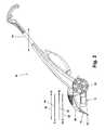
- FIG. 1is a perspective view of an upright extraction cleaning machine according to the invention.
- FIG. 2is a side elevation view of the upright extraction cleaning machine illustrated in FIG. 1 showing movement of the upright extraction cleaning machine during wetting and drying of a surface to be cleaned.
- FIG. 3is a partial sectional side view of the extraction cleaning machine of FIG. 1 illustrating the location of a pair of cleaning fluid spray dispenser assemblies for alternately delivering cleaning fluid to a surface to be cleaned.
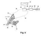
- FIG. 4is a schematic representation of the delivery of cleaning fluid from a first cleaning fluid spray dispenser assembly during forward movement of the extraction cleaning machine of FIG. 1 .
- FIG. 5is a schematic representation of the delivery of cleaning fluid from a second cleaning fluid spray dispenser assembly during rearward movement of the extraction cleaning machine of FIG. 1 .
- FIGS. 1 and 2an embodiment of the invention is illustrated comprising a portable extraction cleaning machine 10 having a base module 12 with wheels 22 to support the module 12 for movement along a surface to be cleaned, and an upright handle assembly 14 pivotally mounted to a rear portion of the base module 12 for manipulating the base module 12 for cleaning the surface.
- the inventionis described and illustrated herein with respect to an embodiment comprising an upright extraction cleaning machine, although the invention can also be utilized in a canister-type cleaning machine.
- the upright extraction cleaning machine 10is a generally well-known device comprising several of the features and operations described in U.S. Pat. No. 6,131,237 to Kasper et al., which is incorporated herein by reference in its entirety. Such well-known features and operations will not be described in detail herein, except as otherwise necessary for a complete understanding of the invention.
- the extraction cleaning machine 10is intended to be moved in alternating forward and rearward directions during the cleaning process, as illustrated by the two headed arrow.
- the typical cleaning processinvolves a first wetting pass 30 in a forward direction wherein cleaning solution is applied to the surface to be cleaned, followed by a second wetting pass 32 in a rearward direction wherein cleaning solution is again applied to the surface.
- This movementis followed by a first drying pass 34 in a forward direction wherein the cleaning solution is vacuumed from the surface, and finally a second drying pass 36 in a rearward direction wherein additional vacuuming is performed.
- the base module 12includes a housing 20 having a front portion 16 .
- the housing 20forms an enclosure for a motor 24 operating a well-known liquid vacuum system (not shown), an agitation assembly 26 , a liquid delivery system comprising a plurality of outlet dispensers 40 , 42 for applying liquid to the carpet, liquid reservoirs, and the like.
- the vacuum systemcomprises a suction nozzle 28 at the front portion 16 of the housing 20 adapted for vacuum removal of liquid from the surface to be cleaned.
- a first assembly of outlet dispensers 40for spraying cleaning solution onto the surface.
- the number of outlet dispensers 40can be selected based upon, for example, the pattern of liquid delivery from each dispenser, the width of the cleaning machine 10 , and the desired coverage of the spray pattern from each dispenser 40 .
- the dispensers 40are fluidly connected in a well-known manner to the fluid delivery system of the extraction cleaning machine 10 .
- a second assembly of outlet dispensers 42for spraying cleaning solution onto the surface to be cleaned.
- the number of outlet dispensers 42can be selected upon, for example, the pattern of liquid delivery from each dispenser, the width of the cleaning machine 10 , and the desired coverage of the spray pattern from each dispenser 42 .
- the dispensers 42are fluidly connected in a well-known manner to the fluid delivery system of the extraction cleaning machine 10 .
- the dispensers 40 , 42are positioned relative to the suction nozzle 28 so that when the base module 12 is moved in a forward direction, fluid from the first dispenser assembly 40 remains on the surface to be cleaned until the suction nozzle 28 passes over the wetted area during a rearward pass of the base module 12 .
- fluid from the second dispenser assembly 42 when the base module 12 is moved in a rearward directionwill remain on the surface until the suction nozzle 28 passes over the wetted area during a forward pass of the base module 12 .
- FIGS. 4 and 5illustrate an embodiment of a dispenser control system for controlling the selective delivery of cleaning fluid to the dispensers 40 , 42 . It is anticipated that other configurations of a suitable control system would be evident to a person of ordinary skill in the relevant art, and other configurations are possible without departing from the spirit of the invention.
- the dispensers 40 , 42are fluidly connected to a well-known cleaning fluid reservoir 44 .
- the cleaning fluid reservoir 44is fluidly connected through a cleaning fluid supply line 46 to a valve 48 .
- the valve 48can selectively deliver cleaning fluid to the rear outlet dispenser assembly 40 through a rear dispenser supply line 52 or to the forward outlet dispenser assembly 42 through a forward dispenser supply line 50 .
- the valve 48is operably connected to a suitable control device 54 through a control connection 56 .
- the control device 54is capable of operating the valve 48 in response to an input signal corresponding to the selection of the nozzle assembly 40 , 42 through which cleaning fluid is to be delivered.
- the control device 54is operably connected through a switch connection 60 to a switch 58 which is used to select the dispenser assembly 40 , 42 through which cleaning fluid is to be delivered.
- the switch 58can comprise a well-known hand-operated toggle switch which can toggle between a first actuating position, a second actuating position, and an off position.
- the switch 58can also comprise a mechanism tied to the movement of the base module 12 , such as a magnet-based sensor to generate an actuation signal indicating the direction of rotation of the wheels 22 such as a magnet attached to the wheels that moves past a sensor during rotation of the wheels.
- a switch similar to that described in U.S. Pat. No. 6,681,442 to Coates et al.can automatically generate a first control signal when the handle assembly 14 is telescopically moved in a first direction corresponding to forward movement of the base module 12 , and a second control signal when the handle assembly 14 is telescopically moved in a second direction corresponding to rearward movement of the base module 12 .
- movement of the base module 12 in a forward directionis accompanied by delivery of cleaning fluid from the reservoir 44 to the rear outlet dispenser assembly 40 .
- the cleaning fluidcan then be scrubbed into the carpet by the agitation assembly 26 .
- the base module 12can then be moved in a rearward direction as illustrated in FIG. 5 , accompanied by delivery of cleaning fluid from the reservoir 44 to the forward outlet dispenser assembly 42 .
- the previously deposited cleaning fluid from the rear outlet dispenser assembly 40will be removed from the surface to be cleaned by the vacuum applied through the suction nozzle 28 .
- the cleaning fluid deposited from the forward outlet dispenser assembly 42will remain on the surface to further loosen and suspend dirt for subsequent removal through the suction nozzle 28 upon a subsequent pass of the base module 12 .
- the use of dual alternating dispenser assemblies for delivery of cleaning solution to the surface being cleanedcan facilitate the cleaning of the surface by leaving cleaning solution on the surface for a longer period of time than with a conventional single fluid dispensing mechanism.
- Cleaning fluidcan be discharged through the rear spray dispensers onto the surface to be cleaned during forward travel of the extraction cleaning machine, to be scrubbed by the agitation assembly. Rearward travel of the extraction cleaning machine will result in the cleaning fluid deposited during the forward pass being extracted through the suction nozzle in a well-known manner.
- additional cleaning fluidwill be deposited through the forward spray dispensers during the rearward travel of the extraction cleaning machine, thereby increasing the period of time during which cleaning fluid is applied to the surface being cleaned. This additional time enables the cleaning fluid to more effectively clean the surface.
- an automatic dispensing selection switching devicecan deliver the cleaning solution to the selected dispensing assembly without the necessity of operator input.
- the use of the switching devicewill ensure that the cleaning fluid is properly applied to the surface to be cleaned.
- the liquid vacuum system, the cleaning fluid reservoir 44 , the control device 54 , and the valve 48can be housed in the canister.
- the suction nozzle 28 and the outlet dispensers 40 , 42can be housed in the wand head in a configuration similar to that described and illustrated for the upright extraction cleaning machine 10 .
- the switch 58can be placed at a suitable position on the wand. Supply lines extending from the wand head to the canister fluidly interconnect the outlet dispensers 40 , 42 with the cleaning fluid reservoir 44 , the control device 54 , and the valve 48 .
- the switch 58would be tied to the movement of the wand, rather than the base module.
- a magnet-based sensorcould be tied to the direction of rotation of wheels in the head, such as a magnet attached to the wheel that moves past a sensor during rotation of the wheel.
- a switch similar to that described in U.S. Pat. No. 6,681,442 to Coates et al.could generate signals corresponding to telescopic movement of the wand in a forward or rearward direction.
Landscapes
- Cleaning In General (AREA)
Abstract
Description
Claims (12)
Priority Applications (1)
| Application Number | Priority Date | Filing Date | Title |
|---|---|---|---|
| US12/389,948US8349088B1 (en) | 2005-01-07 | 2009-02-20 | Extraction cleaning with alternating fluid distribution |
Applications Claiming Priority (3)
| Application Number | Priority Date | Filing Date | Title |
|---|---|---|---|
| US59336005P | 2005-01-07 | 2005-01-07 | |
| US11/275,472US7904990B1 (en) | 2005-01-07 | 2006-01-06 | Extraction cleaning with alternating fluid distribution |
| US12/389,948US8349088B1 (en) | 2005-01-07 | 2009-02-20 | Extraction cleaning with alternating fluid distribution |
Related Parent Applications (1)
| Application Number | Title | Priority Date | Filing Date |
|---|---|---|---|
| US11/275,472ContinuationUS7904990B1 (en) | 2005-01-07 | 2006-01-06 | Extraction cleaning with alternating fluid distribution |
Publications (1)
| Publication Number | Publication Date |
|---|---|
| US8349088B1true US8349088B1 (en) | 2013-01-08 |
Family
ID=43708063
Family Applications (2)
| Application Number | Title | Priority Date | Filing Date |
|---|---|---|---|
| US11/275,472Active2028-07-30US7904990B1 (en) | 2005-01-07 | 2006-01-06 | Extraction cleaning with alternating fluid distribution |
| US12/389,948Active2027-01-31US8349088B1 (en) | 2005-01-07 | 2009-02-20 | Extraction cleaning with alternating fluid distribution |
Family Applications Before (1)
| Application Number | Title | Priority Date | Filing Date |
|---|---|---|---|
| US11/275,472Active2028-07-30US7904990B1 (en) | 2005-01-07 | 2006-01-06 | Extraction cleaning with alternating fluid distribution |
Country Status (1)
| Country | Link |
|---|---|
| US (2) | US7904990B1 (en) |
Cited By (7)
| Publication number | Priority date | Publication date | Assignee | Title |
|---|---|---|---|---|
| US9949602B2 (en) | 2011-11-03 | 2018-04-24 | Techtronic Floor Care Technology Limited | Vacuum axle with a motor embedded therein and wheels |
| US10813520B2 (en) | 2017-12-18 | 2020-10-27 | Techtronic Floor Care Technology Limited | Surface cleaning device with triggerless fluid distribution mechanism |
| US11382477B2 (en) | 2017-12-18 | 2022-07-12 | Techtronic Floor Care Technology Limited | Surface cleaning device with automated control |
| US11484174B2 (en) | 2018-09-21 | 2022-11-01 | Techtronic Floor Care Technology Limited | Cleaning tool for an extractor |
| USD1017156S1 (en) | 2022-05-09 | 2024-03-05 | Dupray Ventures Inc. | Cleaner |
| US12011129B1 (en) | 2023-01-20 | 2024-06-18 | Sharkninja Operating Llc | Extraction cleaner |
| US12096905B2 (en) | 2021-03-17 | 2024-09-24 | Dupray Ventures Inc. | Spot cleaner apparatus |
Families Citing this family (6)
| Publication number | Priority date | Publication date | Assignee | Title |
|---|---|---|---|---|
| ES2571739T3 (en)* | 2007-05-09 | 2016-05-26 | Irobot Corp | Autonomous compact covering robot |
| US8230549B2 (en)* | 2008-03-14 | 2012-07-31 | Bissell Homecare, Inc. | Upright extractor |
| US20150245758A1 (en)* | 2014-02-28 | 2015-09-03 | Rug Doctor, LLC | Liquid Extraction Cleaning Device |
| EP3366182A1 (en)* | 2017-02-27 | 2018-08-29 | Koninklijke Philips N.V. | Cleaning device |
| EP3897330B1 (en) | 2018-12-21 | 2023-09-06 | Tennant Company | Sweeper/scrubber system capable of handling large debris |
| WO2021207424A1 (en)* | 2020-04-08 | 2021-10-14 | Techtronic Cordless Gp | Floor cleaner |
Citations (10)
| Publication number | Priority date | Publication date | Assignee | Title |
|---|---|---|---|---|
| US4014067A (en)* | 1975-06-20 | 1977-03-29 | Charles Ross Bates | Carpet cleaning implement |
| US4167799A (en)* | 1978-05-10 | 1979-09-18 | Webb Charles F | Carpet cleaning machine |
| US4295243A (en)* | 1979-10-15 | 1981-10-20 | King Virginia B | Floor treating apparatus |
| US5237720A (en) | 1990-05-04 | 1993-08-24 | Bissell Inc. | Carpet extractor with bucket caddy |
| US6131237A (en)* | 1997-07-09 | 2000-10-17 | Bissell Homecare, Inc. | Upright extraction cleaning machine |
| US20020092115A1 (en)* | 2001-01-12 | 2002-07-18 | Zahuranec Terry L. | Mixing pump for carpet extractor |
| US6453506B1 (en)* | 2001-02-27 | 2002-09-24 | Gary Sumner | Carpet steam cleaning apparatus with control for directing spray at front or back of wand vacuum head |
| US20030159232A1 (en)* | 2002-02-22 | 2003-08-28 | Hekman Frederick A. | Dual mode carpet cleaning apparatus utilizing an extraction device and a soil transfer cleaning medium |
| US6681442B2 (en)* | 2001-05-21 | 2004-01-27 | The Hoover Company | Apparatus and method for cleaning a surface |
| US20050091782A1 (en)* | 2003-10-30 | 2005-05-05 | Gordon Evan A. | Cleaning machine for cleaning a surface |
- 2006
- 2006-01-06USUS11/275,472patent/US7904990B1/enactiveActive
- 2009
- 2009-02-20USUS12/389,948patent/US8349088B1/enactiveActive
Patent Citations (12)
| Publication number | Priority date | Publication date | Assignee | Title |
|---|---|---|---|---|
| US4014067A (en)* | 1975-06-20 | 1977-03-29 | Charles Ross Bates | Carpet cleaning implement |
| US4167799A (en)* | 1978-05-10 | 1979-09-18 | Webb Charles F | Carpet cleaning machine |
| US4295243A (en)* | 1979-10-15 | 1981-10-20 | King Virginia B | Floor treating apparatus |
| US5237720A (en) | 1990-05-04 | 1993-08-24 | Bissell Inc. | Carpet extractor with bucket caddy |
| US6131237A (en)* | 1997-07-09 | 2000-10-17 | Bissell Homecare, Inc. | Upright extraction cleaning machine |
| US20020092115A1 (en)* | 2001-01-12 | 2002-07-18 | Zahuranec Terry L. | Mixing pump for carpet extractor |
| US6513188B2 (en) | 2001-01-12 | 2003-02-04 | Royal Appliance Mfg. Co. | Mixing pump for carpet extractor |
| US6453506B1 (en)* | 2001-02-27 | 2002-09-24 | Gary Sumner | Carpet steam cleaning apparatus with control for directing spray at front or back of wand vacuum head |
| US6681442B2 (en)* | 2001-05-21 | 2004-01-27 | The Hoover Company | Apparatus and method for cleaning a surface |
| US20030159232A1 (en)* | 2002-02-22 | 2003-08-28 | Hekman Frederick A. | Dual mode carpet cleaning apparatus utilizing an extraction device and a soil transfer cleaning medium |
| US20050091782A1 (en)* | 2003-10-30 | 2005-05-05 | Gordon Evan A. | Cleaning machine for cleaning a surface |
| US7392566B2 (en)* | 2003-10-30 | 2008-07-01 | Gordon Evan A | Cleaning machine for cleaning a surface |
Cited By (17)
| Publication number | Priority date | Publication date | Assignee | Title |
|---|---|---|---|---|
| US9949602B2 (en) | 2011-11-03 | 2018-04-24 | Techtronic Floor Care Technology Limited | Vacuum axle with a motor embedded therein and wheels |
| US12185889B2 (en) | 2017-12-18 | 2025-01-07 | Techtronic Floor Care Technology Limited | Surface cleaning device with triggerless fluid distribution mechanism |
| US10813520B2 (en) | 2017-12-18 | 2020-10-27 | Techtronic Floor Care Technology Limited | Surface cleaning device with triggerless fluid distribution mechanism |
| US10813521B2 (en) | 2017-12-18 | 2020-10-27 | Techtronic Floor Care Technology Limited | Surface cleaning device with triggerless fluid distribution mechanism |
| US10813519B2 (en) | 2017-12-18 | 2020-10-27 | Techtronic Floor Care Technology Limited | Surface cleaning device with triggerless fluid distribution mechanism |
| US10820770B2 (en) | 2017-12-18 | 2020-11-03 | Techtronic Floor Care Technology Limited | Surface cleaning device with triggerless fluid distribution mechanism |
| US11122952B2 (en) | 2017-12-18 | 2021-09-21 | Techtronic Floor Care Technology Limited | Surface cleaning device with automated suction control |
| US11382477B2 (en) | 2017-12-18 | 2022-07-12 | Techtronic Floor Care Technology Limited | Surface cleaning device with automated control |
| US11395571B2 (en) | 2017-12-18 | 2022-07-26 | Techtronic Floor Care Technology Limited | Surface cleaning device with triggerless fluid distribution mechanism |
| US11896176B2 (en) | 2017-12-18 | 2024-02-13 | Techtronic Floor Care Technology Limited | Surface cleaning device with triggerless fluid distribution mechanism |
| US12201251B2 (en) | 2017-12-18 | 2025-01-21 | Techtronic Floor Care Technology Limited | Surface cleaning device with automated control |
| US11944248B2 (en) | 2017-12-18 | 2024-04-02 | Techtronic Floor Care Technology Limited | Surface cleaning device with automated control |
| US11484174B2 (en) | 2018-09-21 | 2022-11-01 | Techtronic Floor Care Technology Limited | Cleaning tool for an extractor |
| US12096905B2 (en) | 2021-03-17 | 2024-09-24 | Dupray Ventures Inc. | Spot cleaner apparatus |
| USD1017156S1 (en) | 2022-05-09 | 2024-03-05 | Dupray Ventures Inc. | Cleaner |
| US12011129B1 (en) | 2023-01-20 | 2024-06-18 | Sharkninja Operating Llc | Extraction cleaner |
| US12336682B2 (en) | 2023-01-20 | 2025-06-24 | Sharkninja Operating Llc | Extraction cleaner |
Also Published As
| Publication number | Publication date |
|---|---|
| US7904990B1 (en) | 2011-03-15 |
Similar Documents
| Publication | Publication Date | Title |
|---|---|---|
| US8349088B1 (en) | Extraction cleaning with alternating fluid distribution | |
| US11779176B2 (en) | Self-cleaning system and method for extraction cleaners | |
| US6684452B2 (en) | Dual cleaning mode carpet extractor | |
| US6735812B2 (en) | Dual mode carpet cleaning apparatus utilizing an extraction device and a soil transfer cleaning medium | |
| EP1753335B1 (en) | Secondary introduction of fluid into vacuum system | |
| US8991000B2 (en) | Low moisture extraction deep cleaning | |
| US20060236494A1 (en) | Hard and soft floor surface cleaner | |
| US20070214595A1 (en) | Machine for cleaning a surface | |
| US20060248677A1 (en) | Wand for a carpet extractor | |
| EP4149337B1 (en) | Fluid dispensing system and method | |
| CN113873929B (en) | floor cleaner | |
| GB2501746A (en) | Mobile floor treatment machine | |
| JP2006026078A (en) | Floor face washing apparatus |
Legal Events
| Date | Code | Title | Description |
|---|---|---|---|
| AS | Assignment | Owner name:BISSELL HOMECARE, INC., MICHIGAN Free format text:ASSIGNMENT OF ASSIGNORS INTEREST;ASSIGNOR:MINER, JONATHAN L.;REEL/FRAME:022291/0197 Effective date:20060104 | |
| STCF | Information on status: patent grant | Free format text:PATENTED CASE | |
| AS | Assignment | Owner name:JPMORGAN CHASE BANK, N.A., AS COLLATERAL AGENT, IL Free format text:SECURITY INTEREST;ASSIGNOR:BISSELL HOMECARE, INC.;REEL/FRAME:032458/0759 Effective date:20140219 | |
| AS | Assignment | Owner name:BISSELL HOMECARE, INC., MICHIGAN Free format text:RELEASE BY SECURED PARTY;ASSIGNOR:JPMORGAN CHASE BANK, N.A.;REEL/FRAME:036608/0704 Effective date:20150908 | |
| FPAY | Fee payment | Year of fee payment:4 | |
| AS | Assignment | Owner name:BISSEL INC., MICHIGAN Free format text:ASSIGNMENT OF ASSIGNORS INTEREST;ASSIGNOR:BISSEL HOMECARE, INC.;REEL/FRAME:051491/0052 Effective date:20191220 | |
| AS | Assignment | Owner name:BISSELL INC., MICHIGAN Free format text:CORRECTIVE ASSIGNMENT TO CORRECT THE SPELLING OF THE CONVEYING PARTY NAME PREVIOUSLY RECORDED AT REEL: 051491 FRAME: 0052. ASSIGNOR(S) HEREBY CONFIRMS THE ASSIGNMENT;ASSIGNOR:BISSELL HOMECARE, INC.;REEL/FRAME:052148/0167 Effective date:20191220 | |
| MAFP | Maintenance fee payment | Free format text:PAYMENT OF MAINTENANCE FEE, 8TH YEAR, LARGE ENTITY (ORIGINAL EVENT CODE: M1552); ENTITY STATUS OF PATENT OWNER: LARGE ENTITY Year of fee payment:8 | |
| MAFP | Maintenance fee payment | Free format text:PAYMENT OF MAINTENANCE FEE, 12TH YEAR, LARGE ENTITY (ORIGINAL EVENT CODE: M1553); ENTITY STATUS OF PATENT OWNER: LARGE ENTITY Year of fee payment:12 |