US8348987B2 - Balloon with scoring member - Google Patents
Balloon with scoring memberDownload PDFInfo
- Publication number
- US8348987B2 US8348987B2US12/645,122US64512209AUS8348987B2US 8348987 B2US8348987 B2US 8348987B2US 64512209 AUS64512209 AUS 64512209AUS 8348987 B2US8348987 B2US 8348987B2
- Authority
- US
- United States
- Prior art keywords
- balloon
- scoring
- scoring structure
- catheter
- diameter
- Prior art date
- Legal status (The legal status is an assumption and is not a legal conclusion. Google has not performed a legal analysis and makes no representation as to the accuracy of the status listed.)
- Active, expires
Links
- 230000010339dilationEffects0.000claimsdescription66
- 239000012530fluidSubstances0.000claimsdescription9
- 238000004891communicationMethods0.000claimsdescription6
- 239000013013elastic materialSubstances0.000claimsdescription4
- 229910001000nickel titaniumInorganic materials0.000claimsdescription4
- HLXZNVUGXRDIFK-UHFFFAOYSA-Nnickel titaniumChemical compound[Ti].[Ti].[Ti].[Ti].[Ti].[Ti].[Ti].[Ti].[Ti].[Ti].[Ti].[Ni].[Ni].[Ni].[Ni].[Ni].[Ni].[Ni].[Ni].[Ni].[Ni].[Ni].[Ni].[Ni].[Ni]HLXZNVUGXRDIFK-UHFFFAOYSA-N0.000claimsdescription3
- 230000003902lesionEffects0.000description29
- 238000000034methodMethods0.000description15
- 239000000463materialSubstances0.000description13
- 208000031481Pathologic ConstrictionDiseases0.000description12
- 238000002399angioplastyMethods0.000description10
- 238000005520cutting processMethods0.000description9
- 230000036262stenosisEffects0.000description9
- 208000037804stenosisDiseases0.000description9
- 238000002594fluoroscopyMethods0.000description5
- 238000004519manufacturing processMethods0.000description5
- 230000008569processEffects0.000description5
- FAPWRFPIFSIZLT-UHFFFAOYSA-MSodium chlorideChemical compound[Na+].[Cl-]FAPWRFPIFSIZLT-UHFFFAOYSA-M0.000description4
- 210000001367arteryAnatomy0.000description4
- 230000000875corresponding effectEffects0.000description4
- 238000003384imaging methodMethods0.000description4
- BASFCYQUMIYNBI-UHFFFAOYSA-NplatinumChemical compound[Pt]BASFCYQUMIYNBI-UHFFFAOYSA-N0.000description4
- 210000001519tissueAnatomy0.000description4
- 210000005166vasculatureAnatomy0.000description4
- 238000009954braidingMethods0.000description3
- 210000004351coronary vesselAnatomy0.000description3
- 230000004069differentiationEffects0.000description3
- 230000000873masking effectEffects0.000description3
- 230000001338necrotic effectEffects0.000description3
- 238000005498polishingMethods0.000description3
- 229920000139polyethylene terephthalatePolymers0.000description3
- 239000005020polyethylene terephthalateSubstances0.000description3
- 238000001356surgical procedureMethods0.000description3
- 238000012800visualizationMethods0.000description3
- 239000004677NylonSubstances0.000description2
- 239000000853adhesiveSubstances0.000description2
- 230000001070adhesive effectEffects0.000description2
- 210000000709aortaAnatomy0.000description2
- 230000017531blood circulationEffects0.000description2
- 210000004204blood vesselAnatomy0.000description2
- 210000001715carotid arteryAnatomy0.000description2
- HVYWMOMLDIMFJA-DPAQBDIFSA-NcholesterolChemical compoundC1C=C2C[C@@H](O)CC[C@]2(C)[C@@H]2[C@@H]1[C@@H]1CC[C@H]([C@H](C)CCCC(C)C)[C@@]1(C)CC2HVYWMOMLDIMFJA-DPAQBDIFSA-N0.000description2
- 230000000916dilatatory effectEffects0.000description2
- PCHJSUWPFVWCPO-UHFFFAOYSA-NgoldChemical compound[Au]PCHJSUWPFVWCPO-UHFFFAOYSA-N0.000description2
- 229910052737goldInorganic materials0.000description2
- 239000010931goldSubstances0.000description2
- 238000003780insertionMethods0.000description2
- 230000037431insertionEffects0.000description2
- 239000000203mixtureSubstances0.000description2
- 229920001778nylonPolymers0.000description2
- 239000002245particleSubstances0.000description2
- 229910052697platinumInorganic materials0.000description2
- 239000011780sodium chlorideSubstances0.000description2
- WFKWXMTUELFFGS-UHFFFAOYSA-NtungstenChemical compound[W]WFKWXMTUELFFGS-UHFFFAOYSA-N0.000description2
- 229910052721tungstenInorganic materials0.000description2
- 239000010937tungstenSubstances0.000description2
- 206010002329AneurysmDiseases0.000description1
- 201000001320AtherosclerosisDiseases0.000description1
- 208000037260Atherosclerotic PlaqueDiseases0.000description1
- 201000000057Coronary StenosisDiseases0.000description1
- 208000032843HemorrhageDiseases0.000description1
- 208000008589ObesityDiseases0.000description1
- 208000007536ThrombosisDiseases0.000description1
- HZEWFHLRYVTOIW-UHFFFAOYSA-N[Ti].[Ni]Chemical compound[Ti].[Ni]HZEWFHLRYVTOIW-UHFFFAOYSA-N0.000description1
- 238000009825accumulationMethods0.000description1
- 229910045601alloyInorganic materials0.000description1
- 239000000956alloySubstances0.000description1
- 210000005249arterial vasculatureAnatomy0.000description1
- 230000004888barrier functionEffects0.000description1
- 210000000988bone and boneAnatomy0.000description1
- 239000006227byproductSubstances0.000description1
- 210000000038chestAnatomy0.000description1
- 235000012000cholesterolNutrition0.000description1
- 239000002131composite materialSubstances0.000description1
- 239000012141concentrateSubstances0.000description1
- 238000007887coronary angioplastyMethods0.000description1
- 230000002596correlated effectEffects0.000description1
- 238000002788crimpingMethods0.000description1
- 235000005911dietNutrition0.000description1
- 230000037213dietEffects0.000description1
- 238000006073displacement reactionMethods0.000description1
- 238000005530etchingMethods0.000description1
- 239000003925fatSubstances0.000description1
- 238000007730finishing processMethods0.000description1
- 210000004013groinAnatomy0.000description1
- 210000003090iliac arteryAnatomy0.000description1
- 239000007943implantSubstances0.000description1
- 230000000302ischemic effectEffects0.000description1
- 238000003754machiningMethods0.000description1
- 229910052751metalInorganic materials0.000description1
- 239000002184metalSubstances0.000description1
- 230000005012migrationEffects0.000description1
- 238000013508migrationMethods0.000description1
- 238000012986modificationMethods0.000description1
- 230000004048modificationEffects0.000description1
- 235000020824obesityNutrition0.000description1
- -1polyethylene terephthalatePolymers0.000description1
- 229920000642polymerPolymers0.000description1
- 210000003137popliteal arteryAnatomy0.000description1
- 230000001681protective effectEffects0.000description1
- 238000005086pumpingMethods0.000description1
- 238000011084recoveryMethods0.000description1
- 210000002254renal arteryAnatomy0.000description1
- 231100000241scarToxicity0.000description1
- 238000005476solderingMethods0.000description1
- 239000007787solidSubstances0.000description1
- 229910001220stainless steelInorganic materials0.000description1
- 239000010935stainless steelSubstances0.000description1
- 229910001256stainless steel alloyInorganic materials0.000description1
- 239000000126substanceSubstances0.000description1
- 210000000115thoracic cavityAnatomy0.000description1
- XLYOFNOQVPJJNP-UHFFFAOYSA-NwaterSubstancesOXLYOFNOQVPJJNP-UHFFFAOYSA-N0.000description1
- 238000003466weldingMethods0.000description1
Images


Classifications
- A—HUMAN NECESSITIES
- A61—MEDICAL OR VETERINARY SCIENCE; HYGIENE
- A61B—DIAGNOSIS; SURGERY; IDENTIFICATION
- A61B17/00—Surgical instruments, devices or methods
- A61B17/22—Implements for squeezing-off ulcers or the like on inner organs of the body; Implements for scraping-out cavities of body organs, e.g. bones; for invasive removal or destruction of calculus using mechanical vibrations; for removing obstructions in blood vessels, not otherwise provided for
- A—HUMAN NECESSITIES
- A61—MEDICAL OR VETERINARY SCIENCE; HYGIENE
- A61M—DEVICES FOR INTRODUCING MEDIA INTO, OR ONTO, THE BODY; DEVICES FOR TRANSDUCING BODY MEDIA OR FOR TAKING MEDIA FROM THE BODY; DEVICES FOR PRODUCING OR ENDING SLEEP OR STUPOR
- A61M25/00—Catheters; Hollow probes
- A61M25/10—Balloon catheters
- A61M25/104—Balloon catheters used for angioplasty
- A—HUMAN NECESSITIES
- A61—MEDICAL OR VETERINARY SCIENCE; HYGIENE
- A61B—DIAGNOSIS; SURGERY; IDENTIFICATION
- A61B17/00—Surgical instruments, devices or methods
- A61B17/32—Surgical cutting instruments
- A61B17/3205—Excision instruments
- A61B17/3207—Atherectomy devices working by cutting or abrading; Similar devices specially adapted for non-vascular obstructions
- A61B17/320725—Atherectomy devices working by cutting or abrading; Similar devices specially adapted for non-vascular obstructions with radially expandable cutting or abrading elements
- A—HUMAN NECESSITIES
- A61—MEDICAL OR VETERINARY SCIENCE; HYGIENE
- A61B—DIAGNOSIS; SURGERY; IDENTIFICATION
- A61B17/00—Surgical instruments, devices or methods
- A61B17/22—Implements for squeezing-off ulcers or the like on inner organs of the body; Implements for scraping-out cavities of body organs, e.g. bones; for invasive removal or destruction of calculus using mechanical vibrations; for removing obstructions in blood vessels, not otherwise provided for
- A61B2017/22001—Angioplasty, e.g. PCTA
- A—HUMAN NECESSITIES
- A61—MEDICAL OR VETERINARY SCIENCE; HYGIENE
- A61B—DIAGNOSIS; SURGERY; IDENTIFICATION
- A61B17/00—Surgical instruments, devices or methods
- A61B17/22—Implements for squeezing-off ulcers or the like on inner organs of the body; Implements for scraping-out cavities of body organs, e.g. bones; for invasive removal or destruction of calculus using mechanical vibrations; for removing obstructions in blood vessels, not otherwise provided for
- A61B2017/22051—Implements for squeezing-off ulcers or the like on inner organs of the body; Implements for scraping-out cavities of body organs, e.g. bones; for invasive removal or destruction of calculus using mechanical vibrations; for removing obstructions in blood vessels, not otherwise provided for with an inflatable part, e.g. balloon, for positioning, blocking, or immobilisation
- A—HUMAN NECESSITIES
- A61—MEDICAL OR VETERINARY SCIENCE; HYGIENE
- A61B—DIAGNOSIS; SURGERY; IDENTIFICATION
- A61B17/00—Surgical instruments, devices or methods
- A61B17/32—Surgical cutting instruments
- A61B17/3205—Excision instruments
- A61B17/3207—Atherectomy devices working by cutting or abrading; Similar devices specially adapted for non-vascular obstructions
- A61B2017/320741—Atherectomy devices working by cutting or abrading; Similar devices specially adapted for non-vascular obstructions for stripping the intima or the internal plaque from a blood vessel, e.g. for endarterectomy
- A—HUMAN NECESSITIES
- A61—MEDICAL OR VETERINARY SCIENCE; HYGIENE
- A61B—DIAGNOSIS; SURGERY; IDENTIFICATION
- A61B90/00—Instruments, implements or accessories specially adapted for surgery or diagnosis and not covered by any of the groups A61B1/00 - A61B50/00, e.g. for luxation treatment or for protecting wound edges
- A61B90/08—Accessories or related features not otherwise provided for
- A61B2090/0807—Indication means
- A—HUMAN NECESSITIES
- A61—MEDICAL OR VETERINARY SCIENCE; HYGIENE
- A61M—DEVICES FOR INTRODUCING MEDIA INTO, OR ONTO, THE BODY; DEVICES FOR TRANSDUCING BODY MEDIA OR FOR TAKING MEDIA FROM THE BODY; DEVICES FOR PRODUCING OR ENDING SLEEP OR STUPOR
- A61M25/00—Catheters; Hollow probes
- A61M25/10—Balloon catheters
- A61M2025/1043—Balloon catheters with special features or adapted for special applications
- A61M2025/109—Balloon catheters with special features or adapted for special applications having balloons for removing solid matters, e.g. by grasping or scraping plaque, thrombus or other matters that obstruct the flow
- A—HUMAN NECESSITIES
- A61—MEDICAL OR VETERINARY SCIENCE; HYGIENE
- A61M—DEVICES FOR INTRODUCING MEDIA INTO, OR ONTO, THE BODY; DEVICES FOR TRANSDUCING BODY MEDIA OR FOR TAKING MEDIA FROM THE BODY; DEVICES FOR PRODUCING OR ENDING SLEEP OR STUPOR
- A61M25/00—Catheters; Hollow probes
- A61M25/10—Balloon catheters
- A61M25/1018—Balloon inflating or inflation-control devices
- A61M25/10184—Means for controlling or monitoring inflation or deflation
Definitions
- the present inventionrelates generally to medical devices and more particularly to balloon catheters.
- Atherosclerosisbegins with the accumulation of excess fats and cholesterol in a blood vessel.
- Atherosclerotic plaqueforms within the walls of the vessel and may block or restrict blood flow through the vessel. This narrowed portion of the arterial lumen is commonly referred to as a stricture or stenosis.
- the coronary arteries, the aorta, the iliofemoral arteries and the carotid arteriesare most commonly affected by stenosis.
- Athlerosclerotic plaquethere are various types of athlerosclerotic plaque that may form within the vessel wall. For example, some plaque may impede flow and exhibit a calcified or fibrous nature, while other plaque may be considered “vulnerable plaque.” While vulnerable plaque may develop within the arterial walls without generally narrowing the arterial lumen substantially, occlusive lesions may include calcified or fibrous plaque comprising, for example, necrotic tissue. The necrotic tissue associated with fibrous plaque may cause the arterial wall to progressively weaken, and a rupture of the intima can occur, thereby causing aneurysm and hemorrhage.
- Angioplasty procedureshave become a popular alternative for treating coronary stenosis because angioplasty procedures are considerably less invasive than other alternatives.
- stenosis of the coronary arterieshas traditionally been treated with bypass surgery.
- coronary bypass surgeryis a very invasive procedure that is risky and requires a long recovery time for the patient.
- bypass surgeryinvolves splitting the chest bone to open the chest cavity and grafting a replacement vessel onto the heart to bypass the blocked, or stenosed, artery.
- a catheter having a deflated balloon attached theretois inserted into a patient's vessel.
- the balloonis uninflated and collapsed onto the catheter in order to present a low profile which may be passed through vessel lumens.
- the balloonis inflated by pumping a saline solution or a mixture of saline and contrast solution through the catheter to the balloon.
- the ballooninflates, it is forced against the vessel wall and expands radially outward to widen the lumen to partially or fully restore patency to the vessel. This outward expansion of the vessel is typically referred to as dilation.
- the balloon inflationmay also serve to expand the stent and implant it within the artery.
- the balloonis deflated so that it once again collapses onto the delivery system.
- the catheterthen is retracted and removed from the patient's vessel with the balloon in the deflated state.
- the balloon catheteris then retracted from the body. If a stent is mounted on the balloon of the catheter, the stent is left permanently implanted in its expanded state at the desired location in the vessel to provide a support structure that prevents the vessel from collapsing back to its pre-dilated condition.
- a balloon-expandable stent or a self-expandable stentmay be implanted in the dilated region in a follow-up or follow-on procedure.
- stenosed regionsit is not uncommon for stenosed regions to be formed of calcified or fibrous plaque comprising, for example, necrotic tissue. These types of stenosis can be difficult to completely dilate using conventional balloons because they tend to remain intact and resist expansion pressures applied by conventional balloon catheters.
- Angioplasty balloon cathetersare described that may include any of the following aspects in various combinations and may also include any other aspect described below in the written description or in the attached drawings.
- an angioplasty balloon cathetermay include a balloon having a distal portion, and a proximal portion, and an active portion disposed therebetween.
- the active portionmay have a working diameter sized to dilate a vessel wall.
- the balloonmay be mounted on a distal end of a catheter, the catheter including an inflation lumen in fluid communication with an interior region of the balloon.
- the balloonis expandable between a deflated configuration having a first diameter in which the balloon is folded, and an inflated configuration having a second diameter in which the balloon is unfolded. The second, inflated diameter is greater than the first, deflated diameter.
- the balloon catheterfurther includes a circumferentially and longitudinally continuous scoring structure having a diameter in an initial unrestrained state that is smaller than the first diameter of the balloon.
- the scoring structureis disposed around an outer surface of the balloon in an expanded configuration, the scoring structure thereby continually exerting a radially inward compressive force against the balloon such that when the balloon is expanded from the deflated configuration to the inflated configuration, the scoring structure expands in a radially outward direction and remains in continuous compressive contact with at least a portion of the balloon as the balloon unfolds.
- the scoring structurealso contracts in a radially inward direction and remains in continuous compressive contact with at least a portion of the balloon as the balloon deflates to the first diameter, thereby assisting in deflation of the balloon.
- the scoring structuremay be entirely free of attachment to the balloon and the catheter. In one embodiment, the scoring structure may extend at least substantially an entire length of the active portion. In another embodiment, the scoring structure may extend only partially along the length of the active portion.
- the scoring structuremay include a plurality of longitudinal members connecting circumferentially compressible members, the longitudinal members and the circumferentially compressible members having an atraumatic radially inner surface in compressive contact with the balloon, and a radially outer surface shaped to engage and score a vessel wall when the balloon is expanded to the inflated configuration.
- FIG. 1( a )is a side elevation view of a distal end of an embodiment of a scoring balloon catheter in a collapsed configuration
- FIG. 1( b )is a side cross-sectional view of a hub of the scoring balloon catheter of FIG. 1( a ).
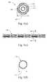
- FIG. 1( c )is a cross-sectional view of a balloon of the scoring balloon catheter in a deflated state along the line X-X of FIG. 1( a );
- FIG. 1( d )is a side elevation view of the balloon of the scoring balloon catheter of FIG. 1( a ) in an inflated state;
- FIG. 1( e )is a side elevation view of the scoring structure of the scoring balloon catheter of FIG. 1( a ) in an initial relaxed configuration
- FIG. 1( f )is a cross-sectional view of the scoring structure of FIG. 1( e ) along the line Y-Y;
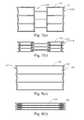
- FIG. 2is a side elevation view of the distal end of the scoring balloon catheter in an expanded configuration
- FIG. 3is a cross-sectional view of the balloon and scoring structure of FIG. 2 along the line X′-X′ in the expanded configuration;
- FIG. 4is a cross-sectional view of the balloon and scoring structure of FIG. 1( a ) along the line X′-X′ in the collapsed configuration;
- FIGS. 5( a )-( g )illustrate various embodiments of the cross-sectional profile of the scoring structure
- FIGS. 6( a ) and ( b )are close-up views of an interface between the balloon and the scoring structure
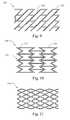
- FIGS. 7( a )- 12 ( b )illustrate a plurality of exemplary scoring structures
- FIGS. 13-15illustrate the dilation of a body lumen using the scoring balloon catheter of FIG. 1( a ), wherein FIG. 13 is a side view of the scoring balloon catheter of FIG. 1( a ) in a collapsed configuration prior to dilation of a body lumen;
- FIG. 14is a side view of the scoring balloon catheter of FIG. 13 in the expanded configuration dilating the body lumen;
- FIG. 15is a side view of the scoring balloon catheter of FIG. 13 in a collapsed state after dilation of the body lumen;
- FIG. 16( a )is a side elevation view of a first portion of a circumferentially asymmetric embodiment of the scoring structure
- FIG. 16( b )is a side elevation view of a second portion of the asymmetric scoring structure of FIG. 15( a );
- FIG. 16( c )is an end view of the asymmetric scoring structure
- FIG. 16( d )is a perspective view of the asymmetric scoring structure
- FIG. 16( e )is a side elevation view of a first side of an embodiment of the asymmetric scoring structure of FIGS. 16( a )-( e );
- FIG. 16( f )is a side elevation view of a second side of the asymmetric scoring structure
- FIGS. 17 ( a )-( c )illustrate different embodiments of the orientation/identification indicator of the embodiment of FIGS. 16( e ) and ( f );
- FIGS. 18( a ) and ( b )illustrate another embodiment of the asymmetrical scoring structure of FIGS. 16( a )-( d ).
- FIGS. 1( a )-( f )illustrate an embodiment of a scoring balloon catheter 10 for scoring a calcified/fibrous lesion and dilating a body lumen (e.g. a vessel or duct).
- a scoring balloon catheter 10may include a dilation balloon 100 , a scoring structure 120 , a catheter 110 , and a hub 20 ( FIG. 1( b )).
- the dilation balloon 100may have proximal and distal tapered portions 101 that extend from the proximal and distal ends of a working region 108 to the proximal and distal ends of the dilation balloon 102 , 104 , respectively.
- the working region 108In its inflated state, the working region 108 has a generally cylindrical, constant radius shape, and a length that is sized to substantially correspond to a length of the portion of a body lumen (e.g. a stenosis or lesion) to be dilated.
- the working region 108may have a length ranging between about 20 mm to about 120 mm, and between about 20 mm and 40 mm in another embodiment.
- the dilation balloon 100may be sized to expand stenoses/lesions in the aorta, iliac, renal, coronary, popliteal, and carotid arteries, which typically have diameters ranging between about 2.0 mm and about 40 mm. Accordingly, the scoring balloon catheter 10 may range in size from 6 French or smaller up to approximately 15 French or larger.
- the dilation balloon 100is configured to be expandable between a deflated and folded configuration having a diameter 107 ( FIG. 1( c )), to an inflated configuration having a diameter 109 ( FIG. 1( d )). Because the purpose of the dilation balloon is to engage and expand a constricted body lumen, the inflated diameter of the dilation balloon 100 substantially matches the expected healthy diameter of the body lumen, which may be determined using the diameters of healthy unconstricted vessels disposed near or at one or both sides of the constriction. Accordingly, in one embodiment, the inflated diameter 109 of the dilation balloon 100 also ranges between about 2.0 mm and about 40 mm.
- the dilation balloon 100may be made of a material having sufficient strength to prevent puncture or tearing when expanded against the sharp protrusions of a calcified lesion. Additionally, in order to avoid over expansion and rupturing of the blood vessel, the dilation balloon 100 may be constructed of materials that maintain their original shape when inflated to 8-20, or to greater than 20 atmospheres of pressure. Thus, the dilation balloon 100 may be made from a material that is substantially inelastic within the working pressure range of 14-20 atmospheres. For example, the balloon 100 may be made from polyethylene terephthalate (PET) or Nylon.
- PETpolyethylene terephthalate
- NylonNylon
- the scoring balloon catheter 10may be used in body lumens having diameters of approximately 2.0 mm or less.
- the balloon wallmay be as thin as possible to minimize the folded, deflated diameter of the balloon 107 .
- the dilation balloon 100may be made of a material that is strong enough to withstand dilation pressures using a very thin wall.
- Exemplary dilation balloonssuch as the Cook Accent Balloon Angioplasty Catheter, ATB PTA Dilatation Catheter, and Advance Low-Profile Balloon Dilatation Catheter balloon, made by Cook Incorporated, the assignee of the present application, are typically made from nylon or PET having a wall thickness of 0.0038 mm.
- the dilation balloon 100in the deflated state, forms a plurality of folds 106 to achieve a minimal diameter 107 for delivery of the scoring balloon catheter 10 to a treatment site in a patient's vasculature, e.g. a calcified or fibrous lesion.
- the balloon 100may be folded such that the folds 106 wrap around the catheter 110 in an overlapping configuration, as shown in FIG. 1( a ).
- the present embodimentis not limited thereto, and the dilation balloon 100 may be folded in any configuration that results in a sufficiently small deflated diameter 107 for insertion into a body lumen.
- the dilation balloon 100is hermetically sealed to the catheter 110 at the proximal and distal ends 102 , 104 .
- the catheter 110includes at least two lumens, an inflation lumen 112 in fluid communication with the interior space defined by the inner surface of the dilation balloon 100 , and a guidewire lumen 114 adapted to receive a guidewire and allow contrast fluid or the like to be delivered to the treatment site.
- the inflation lumen 112 and the guidewire lumen 114may be formed by two catheter tubes arranged in a substantially coaxial configuration, as shown in FIGS. 1( b ) and ( c ). Alternatively, the inflation lumen 112 and the guidewire lumen 114 may be integrally formed in a single catheter tube.
- the inflation lumen 112is connected to an inflation port 22 on the hub 20 and extends to at least the proximal end 104 of the balloon 100 .
- the guidewire lumen 114is connected to a guidewire port 24 , and extends distally through an entire length of the balloon 100 to at least the distal end 102 such that the guidewire lumen 114 passes through, but is not in fluid communication with, the interior space of the dilation balloon 100 .
- the present embodimentis not limited thereto, and other guidewire and inflation lumen 112 , 114 configurations are contemplated, including, but not limited to rapid exchange configurations.
- the scoring structure 120is completely free of attachment to the dilation balloon 100 and the catheter 110 .
- the scoring structure 120may be formed of a plurality of structural members 122 connected by bends in an undulating pattern, and appears much like a balloon or self-expanding stent. However, unlike a self-expanding stent which has a fully expanded relaxed configuration, the scoring structure 120 has a relaxed configuration in which the diameter is reduced. Furthermore, because the scoring structure's 120 relaxed position is at its reduced diameter, it differs from a balloon expandable stent in that upon being expanded by the dilation balloon 100 , the scoring structure 120 returns to its relaxed, reduced diameter state, as described below in detail. Thus, the scoring structure 120 expands and contracts with the inflation and deflation of the balloon 100 and is not capable of being implanted to support a body lumen. Stated differently, the scoring structure 120 is not capable of acting as a stent.
- the structural members 122are connected in an undulating pattern to form ring structures 125 having a substantially cylindrical shape.
- Each of the ring structures 125are connected by longitudinal connecting members 124 , resulting in a substantially continuous scoring structure 120 that extends substantially the entire length and circumference of the working region 108 .
- the scoring structure 120may also include radiopaque markers 126 disposed at the proximal and distal ends of the scoring structure 120 to allow for fluoroscopic visualization and placement of the scoring balloon catheter 10 within a body lumen.
- the radiopaque markersmay be made of gold, tungsten, or platinum, or the like, as is known in the art, and may be formed as rivets attached to the scoring structure 120 .
- portions of the proximal and distal ends of the scoring structure 120may be coated with a radiopaque material.
- the scoring structure 120may be made of an elastic material or a super-elastic material.
- the scoring structure 120may be made from stainless steel or Nitinol, which allow the scoring structure 120 to expand and contract with the dilation balloon 100 without plastically deforming as the dilation balloon 100 is inflated to its maximum diameter 109 , as shown in FIGS. 1( d ) and 2 , and deflated, as shown in FIGS. 1( a ) and ( c ). Because the scoring structure 120 has a reduced diameter 123 that is less than the minimum diameter 107 of the dilation balloon 100 , the scoring structure 120 continuously applies a compressive, radially inward force against the dilation balloon 100 in its deflated, inflated, and intermediate states.
- This compressive force exerted by the scoring structure 120 on the dilation balloon 100may result in frictional force between the scoring structure 120 and the balloon 100 that prevents unwanted or unintended migration or displacement of the scoring structure 120 relative to the working region 108 during manufacturing and use.
- the need for physical attachment of the scoring structure 120 to the dilation balloon 100may be obviated.
- the scoring structuremay be attached to the dilation balloon 100 , the catheter 110 , or other portions of the balloon catheter 10 by a wire, suture, or other means known in the art.
- the scoring structure 120is free of attachment to the dilation balloon 100 and the catheter 110 , it offers significant manufacturing and operational advantages over conventional scoring balloons.
- conventional scoring balloons employing metallic cutting members attached to the surface of a dilation balloonmust be carefully folded to avoid contact between the sharp outer edge of the cutting member and the balloon to prevent the cutting member from lacerating or otherwise damaging the balloon during both manufacturing and inflation.
- attaching the cutting members to the balloon in such cathetersis difficult because the metal cutting members and the polymer balloon are dissimilar materials.
- the scoring balloon catheter 10 of the present embodimentrequires no specialized folding techniques or machinery and can be folded in substantially the same manner as a conventional angioplasty balloon catheter.
- the scoring structure 120utilizes the compressive force to maintain its position relative to the dilation balloon 100 , the scoring structure 120 requires no adhesive or crimping processes to place the scoring structure 120 on the dilation balloon 100 , thereby dramatically simplifying the manufacturing process.
- circumferentially adjacent structural members 122are substantially parallel to each other.
- the radially outward force exerted on the scoring structure 120 by the dilation balloon 100causes the substantially parallel structural members 122 to flex away from each other, thereby increasing the diameter of the scoring structure 120 and allowing the dilation balloon 100 to expand.
- the folds 106begin to unfold and slide along the inner surface of the scoring structure 120 until the dilation balloon achieves its maximum inflated diameter 109 , as shown in FIGS. 3-4 .
- the radially inward compressive force exerted by the scoring structure 120assists in the deflation process and ensures that the scoring structure 120 remains in contact with the outermost portion of the surface of the dilation balloon 100 .
- the scoring structure 120forces the balloon to fold in on itself until the compressive force exerted by the scoring structure 120 cannot compress the balloon any further. At this point, the dilation balloon 100 achieves a relaxed state approximating the minimum diameter 107 .
- the scoring structure 120may be formed using the same processes known in the art to form stents, for example and without limitation, cannula or sheet cutting, and braiding.
- cannula and sheet cuttinga desired arrangement of structural and longitudinal connecting members 124 , 122 is cut into a metallic cannula or sheet using a laser or the like. This process typically results in relatively sharp edges along the cutting lines and may produce small, sharp protrusions along the edges of the structural and longitudinal connecting members 124 , 122 .
- the metallic sheetonce the desired geometry of the scoring structure 120 is cut, the sheet is rolled into a cylindrical form and welded or soldered together to form a tube, as is known in the art.
- FIGS. 7-10 , and 12illustrate several exemplary embodiments of a cannula or sheet cut scoring structure 120
- FIG. 11illustrates a scoring structure 120 formed by braiding or otherwise attaching a plurality of wire filaments together.
- FIGS. 7( a ) and ( b )illustrate a scoring structure 120 in an expanded and initial form, respectively.
- the scoring structure 120has four ring structures 125 formed of interconnected structural members 122 that are connected by a plurality of longitudinal connecting members 124 to produce a scoring pattern having plurality of longitudinally staggered, substantially straight-lines for engaging a calcified or fibrous lesion.
- FIGS. 1-10 , and 12illustrate several exemplary embodiments of a cannula or sheet cut scoring structure 120
- FIG. 11illustrates a scoring structure 120 formed by braiding or otherwise attaching a plurality of wire filaments together.
- FIGS. 7( a ) and ( b )illustrate a scoring structure 120 in an expanded and initial form, respectively.
- FIGS. 8( a ) and ( b )illustrate a scoring structure 120 having two ring structures 125 disposed at opposite ends thereof.
- the ring structures 125are connected by substantially straight longitudinal connecting members 124 .
- the longitudinal connecting members 124extend substantially the entire length of the scoring structure 120 , and therefore extend substantially the entire length of the working region 108 of the dilation balloon 100 , thereby producing a substantially straight line scoring pattern.
- the longitudinal connecting members 124may extend along the length of the scoring structure 120 in a helical or otherwise non-straight line pattern ( FIGS. 12( a ) and ( b ).
- FIGS. 9 and 10illustrate additional embodiments having a substantially helically extending scoring pattern, and a zigzag pattern, respectively.
- the scoring structure 120may have an outer surface that is shaped to engage and score a lesion or stenosis, and an atraumatic inner surface to prevent the scoring structure from damaging or rupturing the dilation balloon 100 .
- FIGS. 5( a )-( d )illustrate several exemplary integrally formed cross-sectional shapes of the structural members 122 and longitudinal connecting members 124 of the scoring structure 120 .
- the scoring structure 120includes scoring portions 524 a disposed at opposite corners on the radially outer surface of the scoring structure 120 , and an atraumatic portion 522 a disposed on the radially inner surface of the scoring structure 120 .
- the scoring portions 524 aare jagged protrusions, which may be formed as a by-product of the manufacturing process of the scoring structure 120 due to the cannula or sheet cut process described above.
- the scoring structure 120is used “as cut,” thereby leaving the sharp protruding portions to act as scoring portions 524 a .
- the atraumatic portions 522 ( a ) and ( c )may be formed by polishing or otherwise abrading the inner surface of the scoring structure 120 to remove sharp edges that could potentially scar or damage the dilation balloon 100 .
- FIG. 5( c )illustrates a cross-section in which the scoring portion 524 c of the outer surface of the scoring structure 120 includes sharp edged corners.
- FIGS. 5( b ) and ( d )illustrate cross-sections that taper from broad atraumatic surfaces 522 ( b ) and 522 ( d ) disposed at an inner surface of the scoring structure 120 to pointed scoring portions 524 ( b ) and 524 ( d ).
- the pointed scoring portions 524 ( b ) and 524 ( d ) and the atraumatic portions 522 ( b ) and 522 ( d )may be formed by chemical or mechanical etching, or machining for embodiments cut from cannula or sheet.
- the wire filamentsmay be extruded in the cross-sectional shapes illustrated in FIGS. 5( b ) and ( d ).
- FIGS. 5( e )-( g )illustrate cross-sectional views of scoring structures 120 having a composite shape in which a scoring member 540 ( e )-( g ) having a stress concentrating scoring portion 524 ( e )-( g ) is attached to a base portion 550 ( e )-( g ) having an atraumatic inner surface 522 ( e )-( g ).
- the scoring members 540 ( e )-( g )may be attached to the base portions 550 ( e )-( g ) by bonding, welding, soldering or the like, as is known in the art.
- the scoring members 540 ( e )-( g )may be attached to an entire exterior surface of the scoring structure 120 .
- the scoring members 540 ( e )-( g )may be applied to only selected portions of the scoring structure 120 to achieve a desired scoring pattern.
- the scoring structure 120may have a circumferentially asymmetric scoring portion 1510 configured to score and dilate lesions extending only partially around an inner surface of a vessel or duct.
- the asymmetric scoring structure 1500may be formed by cutting two different, fluoroscopically (or otherwise visible from outside the patient) distinguishable geometric patterns of structural members 124 and longitudinal connecting members 122 in a cannula or sheet with a laser, water jet or the like.
- the first geometric patterncorresponds to a scoring section 1510 and the second geometric pattern corresponds to an atraumatic section 1520 .
- the first geometric patternmay correspond to a first portion of the scoring structure 120 that extends partially around the circumference, while the second geometric pattern may correspond to a second portion of the scoring structure extending around the remainder of the circumference. Accordingly, the first and second geometric patterns result in a circumferentially asymmetrical structure that is visually distinguishable in a manner clearly correlated to device orientation using fluoroscopy or the like.
- Both the internal and external surfaces of the scoring structure 1500 having the second geometric pattern corresponding to the atraumatic portion 1520are abraded through electro-polishing or the like, or coated with a layer of material, for example and without limitation, a radiopaque material such as gold, tungsten or platinum, to remove any sharp edges or protrusions that may damage healthy vessel tissue.
- a radiopaque materialsuch as gold, tungsten or platinum
- at least the external portion of the scoring structure 1500 having the first geometric pattern corresponding to the scoring portion 1510is left in the “as-cut” state and/or formed with stress concentrating features 524 as described above in connection with FIGS. 5( a )-( g ).
- the “as cut” configuration of the portion of the scoring portion 1510may be maintained by masking the portions of the scoring structure corresponding to the scoring portion 1510 prior to performing the surface finishing operation, e.g. electro-polishing or the like, which removes the sharp, “as cut” stress concentrating features 524 from the unmasked, atraumatic portion 1520 .
- the maskingprotects the stress concentrating features 524 during the surface finishing operation such that when the masking is removed, the stress concentrating features 524 remain.
- the unmasked, atraumatic portion 1520is exposed to the surface finishing process and is therefore substantially free of stress concentrating features 524 .
- all, or portions of the scoring section 1510 and the atraumatic section 1520may be modified for fluoroscopic visualization and differentiation from each other.
- radiopaque markersmay be attached to the scoring structure 120 at selected points to allow for fluoroscopic differentiation of the two geometric patterns, thereby allowing a physician to determine the orientation of the scoring portion 524 relative to the atraumatic portion 522 .
- the entire scoring structure 120may be doped with a radiopaque material to allow fluoroscopic distinction of the two geometric patterns.
- the asymmetric scoring structure 1500is not limited thereto, and other combinations and placement of radiopaque material on the scoring section 1510 and the atraumatic section 1520 are contemplated.
- FIGS. 16( a )-( d )illustrate the scoring section 1510 and the atraumatic section 1520 as having a particular geometric pattern of structural members 122 and longitudinal connecting members 124 , the geometric patterns are not limited thereto, and any two patterns that are distinguishable from one another under fluoroscopic visualization are contemplated.
- the entire scoring structure 120may have the same or a different geometric pattern of structural members 122 and longitudinal members 124 , and a scoring member 540 made of a radiopaque material may be attached to only a portion of the scoring structure 120 .
- a plurality of scoring members 540may be attached to the asymmetrical scoring structure 1500 in a pattern having, for example, a “V” shape that points in one direction or another, depending on which side the scoring structure 1500 is viewed. That is, when the asymmetric scoring structure 1500 is oriented such that the scoring section 1510 is disposed closest to the fluoroscopic imaging device (e.g. FIG.
- the scoring members 540create an upwardly pointing V-shaped pattern.
- the scoring members 540create a downwardly pointing V-shaped pattern. Accordingly, depending on the direction the V-shaped pattern is pointing, the physician can ascertain the orientation of the scoring section 1510 and the atraumatic section 1520 and can align the scoring section 1510 with portion of the vessel covered by the lesion to be scored.
- the atraumatic section 1520may include an orientation/identification indicator 1600 that allows the physician to identify the orientation of the scoring section 1510 and the atraumatic section 1520 under fluoroscopy.
- the asymmetric scoring structure 1500when the asymmetric scoring structure 1500 is viewed in an orientation where the atraumatic section 1520 is disposed closest to the fluoroscopic imaging device, the asymmetrically extending shape of the orientation/identification indicator 1600 , in this case a “V” shaped portion of a longitudinal member 124 , appears to point upward.
- the orientation/identification indicator 1600appears to point downward.
- the physicianis able to determine where the atraumatic portion 1520 and the scoring portion 1510 are located in the vessel relative to the lesion.
- the physiciancan then manipulate the scoring balloon by rotation or the like to align the scoring section 1510 with portion of the vessel covered by the lesion to be scored.
- FIGS. 16( e ) and ( f )illustrate the orientation/identification indicator(s) 1600 being disposed on the atraumatic section 1520 , it should be understood that the orientation/identification indicator(s) may be disposed on the scoring portion 1510 .
- the asymmetric scoring structure 1500may include a plurality of orientation/identification indicators 1600 that indicate precisely which structural members 122 and longitudinal members 124 comprise the scoring and/or atraumatic sections 1510 , 1520 .
- the orientation/identification indicators 1600are included on at least the structural members 122 and longitudinal members 124 that define the border/edge of the atraumatic section 1520 or the scoring section 1510 and at least one intermediate structural member 122 or longitudinal member 124 thereof to aid the physician in determining which section of the asymmetric scoring structure 1500 that he/she is viewing and its orientation.
- the orientation/identification indicators 1600are shown as pointing upward or downward in FIGS. 16( e ) and ( f ), it should be understood that they are not limited thereto, and the orientation/identification indicators 1600 may be oriented in any direction that allows for identification and differentiation when viewed through fluoroscopy or the like.
- the orientation/identification indicator 1600is not limited to a “V” shape shown in FIGS. 16( e ) and ( f ).
- the orientation/identification indicator 1600may have any shape that results in a distinctly different orientation that is readily apparent when viewed from one side or the other of the asymmetric scoring structure 1500 through fluoroscopy or the like.
- the shape of the orientation/identification indicator 1600may be, for example and without limitation, V-shaped, U-shaped, C-shaped, D-shaped, quadrilateral, oval, or the like.
- the orientation/identification indicator 1600may be a solid tab that is integrally formed with or attached to a longitudinal member 124 or a structural member 122 , as shown in FIG. 17( c ).
- the orientation/identification indicator 1600may also be a longitudinal/structural member 124 , 122 having a particular shape, as shown in FIGS. 16( e ) and ( f ) and 17 ( a ) and ( b ).
- the outer surface of the dilation balloon 100may have a first structure 150 and the atraumatic inner surface 522 of the scoring member 120 may have a second structure 160 .
- the first and second structures 150 , 160may be formed by applying a separate material to the surface of the dilation balloon 100 and the scoring structure 120 with an adhesive 140 or the like.
- the first and second structures 150 , 160may be integrally formed in the surface of the dilation balloon 100 and the scoring structure 120 .
- the first and second structures 150 , 160are shaped to frictionally engaging each other thereby maintaining a longitudinal position of the scoring structure 120 relative to the dilation balloon 100 as the scoring structure 120 expands due to the expansion of the dilation balloon 100 .
- the first and second structures 150 , 160may be a series of grooves and protrusions having a complimentary shape that extends around a circumference of the dilation balloon 100 and the scoring structure 120 , respectively.
- the structures 150 , 160are not limited thereto, and may have any shape capable of frictionally interacting to help maintain the longitudinal position of the scoring structure 120 relative to the dilation balloon 100 .
- the scoring balloon catheter 10is inserted percutaneously (or via cutdown) into a patient's vasculature over a guidewire using the Seldinger technique, which is well known in the art.
- the guidewireis inserted through a small incision, typically made in a patient's groin, arm, or other anatomic location.
- the guidewireis then advanced through the patient's vasculature to the location of the stenosis or lesion 300 (the treatment site). Once the guidewire has passed the lesion 300 in the vessel 200 , a distal tip of the guidewire is placed distally of the lesion 300 .
- the guidewireis inserted into the distal end of the guidewire lumen outside the patient's body and the scoring balloon catheter 20 is advanced along the guidewire to the treatment site.
- a guide cathetermay also be inserted into the patient's vasculature prior to insertion of the scoring balloon catheter 10 , thereby providing a protective barrier between the scoring portion 124 and the vessel.
- the scoring balloon catheter 10is then advanced along a track formed by the guidewire (or along a track formed by the guidewire and through the guide catheter) into the vessel and to the lesion 300 utilizing the radiopaque markers on the scoring structure or the balloon catheter, which are visible under fluoroscopy.
- the asymmetric scoring structure 1500may be employed.
- the physicianutilizes the fluoroscopically distinguishable patterns to “clock” the scoring structure 120 such that the scoring portion 124 is circumferentially aligned with the lesion 300 by rotating the proximal end of the scoring balloon catheter 10 .
- the physicianadvances the scoring balloon catheter 10 out of the guide catheter to expose the scoring structure 120 and the balloon 100 , as shown in FIG. 13 .
- the dilation balloon 100is inflated with a fluid, typically saline solution or a mixture of saline and contrast fluid, which causes the balloon 100 to expand and unfold, thereby expanding the scoring structure 120 .
- a fluidtypically saline solution or a mixture of saline and contrast fluid
- the scoring structure 120concentrates the outward radial force exerted by the dilation balloon 100 at discreet areas, which allows the scoring structure 120 to fracture and/or compress the outer surface of the calcified or fibrous lesion, thereby scoring its surface.
- the dilation balloon 100can more easily and controllably dilate the portion of the vessel 200 corresponding to the lesion 300 utilizing a lower inflation pressure, as compared to an unscored lesion 300 .
- the scoring structure 120may be less likely to dislodge particles of plaque from the lesion 300 if the scoring balloon catheter 10 is inadvertently jostled or rotated once the scoring structure 120 has engaged the lesion 300 , thereby preventing potential complications from such dislodged plaque particles. Further, in embodiments where the scoring structure 120 is not attached to the dilation balloon 100 , the scoring structure 120 may be better able to flex and adapt to the shape of the expanding dilation balloon 100 than in embodiments where the scoring structure 120 is attached to the dilation balloon 100 , thereby helping to ensure that the scoring portion 124 is positioned to most fully engage the lesion 300 .
- the dilation balloon 100is then deflated and the scoring structure 120 contracts towards its relaxed diameter 127 , as illustrated in FIG. 15 .
- the scoring balloon catheter 10is then withdrawn proximally and removed from the vessel.
Landscapes
- Health & Medical Sciences (AREA)
- Life Sciences & Earth Sciences (AREA)
- Heart & Thoracic Surgery (AREA)
- Animal Behavior & Ethology (AREA)
- Vascular Medicine (AREA)
- Surgery (AREA)
- Veterinary Medicine (AREA)
- Public Health (AREA)
- Engineering & Computer Science (AREA)
- General Health & Medical Sciences (AREA)
- Biomedical Technology (AREA)
- Hematology (AREA)
- Anesthesiology (AREA)
- Pulmonology (AREA)
- Biophysics (AREA)
- Orthopedic Medicine & Surgery (AREA)
- Nuclear Medicine, Radiotherapy & Molecular Imaging (AREA)
- Child & Adolescent Psychology (AREA)
- Medical Informatics (AREA)
- Molecular Biology (AREA)
- Media Introduction/Drainage Providing Device (AREA)
Abstract
Description
Claims (17)
Priority Applications (1)
| Application Number | Priority Date | Filing Date | Title |
|---|---|---|---|
| US12/645,122US8348987B2 (en) | 2009-12-22 | 2009-12-22 | Balloon with scoring member |
Applications Claiming Priority (1)
| Application Number | Priority Date | Filing Date | Title |
|---|---|---|---|
| US12/645,122US8348987B2 (en) | 2009-12-22 | 2009-12-22 | Balloon with scoring member |
Publications (2)
| Publication Number | Publication Date |
|---|---|
| US20110152905A1 US20110152905A1 (en) | 2011-06-23 |
| US8348987B2true US8348987B2 (en) | 2013-01-08 |
Family
ID=44152139
Family Applications (1)
| Application Number | Title | Priority Date | Filing Date |
|---|---|---|---|
| US12/645,122Active2030-07-30US8348987B2 (en) | 2009-12-22 | 2009-12-22 | Balloon with scoring member |
Country Status (1)
| Country | Link |
|---|---|
| US (1) | US8348987B2 (en) |
Cited By (40)
| Publication number | Priority date | Publication date | Assignee | Title |
|---|---|---|---|---|
| US8685049B2 (en) | 2010-11-18 | 2014-04-01 | Rex Medical L.P. | Cutting wire assembly for use with a catheter |
| US8685050B2 (en) | 2010-10-06 | 2014-04-01 | Rex Medical L.P. | Cutting wire assembly for use with a catheter |
| US8702736B2 (en) | 2010-11-22 | 2014-04-22 | Rex Medical L.P. | Cutting wire assembly for use with a catheter |
| US9173977B2 (en) | 2010-04-19 | 2015-11-03 | Angioscore, Inc. | Coating formulations for scoring or cutting balloon catheters |
| US9282991B2 (en) | 2010-10-06 | 2016-03-15 | Rex Medical, L.P. | Cutting wire assembly with coating for use with a catheter |
| US9351756B2 (en) | 2010-09-21 | 2016-05-31 | Angioscore, Inc. | Method and system for treating valve stenosis |
| US9375328B2 (en) | 2001-11-09 | 2016-06-28 | Angioscore, Inc. | Balloon catheter with non-deployable stent |
| US9586031B2 (en) | 2005-05-11 | 2017-03-07 | Angioscore, Inc. | Methods and systems for delivering substances into luminal walls |
| US9962529B2 (en) | 2003-01-21 | 2018-05-08 | Angioscore, Inc. | Apparatus and methods for treating hardened vascular lesions |
| US10086178B2 (en) | 2001-11-09 | 2018-10-02 | Angioscore, Inc. | Balloon catheter with non-deployable stent |
| US10117668B2 (en) | 2013-10-08 | 2018-11-06 | The Spectranetics Corporation | Balloon catheter with non-deployable stent having improved stability |
| US10182841B1 (en)* | 2015-06-16 | 2019-01-22 | C.R. Bard, Inc. | Medical balloon with enhanced focused force control |
| EP3473214A1 (en) | 2017-10-18 | 2019-04-24 | Biotronik AG | Balloon catheter-stent device |
| EP3473197A1 (en) | 2017-10-18 | 2019-04-24 | Biotronik AG | Balloon catheter |
| WO2019209696A1 (en)* | 2018-04-24 | 2019-10-31 | TriReme Medical, LLC | Balloon catheter |
| US10463387B2 (en) | 2011-09-13 | 2019-11-05 | John P. Pigott | Intravascular catheter having an expandable incising portion for incising atherosclerotic material located in a blood vessel |
| US10485572B2 (en) | 2011-09-13 | 2019-11-26 | John P. Pigott | Intravascular catheter having an expandable incising portion |
| US10549077B2 (en) | 2010-03-12 | 2020-02-04 | TriReme Medical, LLC | Device and method for compartmental vessel treatment |
| US10603069B2 (en) | 2015-01-13 | 2020-03-31 | John P. Pigott | Intravascular catheter balloon device having a tool for atherectomy or an incising portion for atheromatous plaque scoring |
| US10610255B2 (en) | 2011-09-13 | 2020-04-07 | John P. Pigott | Intravascular catheter having an expandable incising portion and medication delivery system |
| US10828471B2 (en) | 2013-07-15 | 2020-11-10 | John P. Pigott | Balloon catheter having a retractable sheath |
| WO2020227454A1 (en) | 2019-05-07 | 2020-11-12 | Nu-Life Consulting Pte Ltd | Flexible tubular spring structure, and scoring balloon catheter equipped therewith |
| US10869689B2 (en) | 2017-05-03 | 2020-12-22 | Medtronic Vascular, Inc. | Tissue-removing catheter |
| US11000680B2 (en) | 2014-11-17 | 2021-05-11 | TriReme Medical, LLC | Balloon catheter system and method of using same |
| US11033712B2 (en) | 2015-01-13 | 2021-06-15 | Venturemed Group, Inc. | Intravascular catheter having an expandable portion |
| US11154693B2 (en) | 2013-07-15 | 2021-10-26 | John P. Pigott | Balloon catheter having a retractable sheath |
| US11154694B2 (en) | 2013-07-15 | 2021-10-26 | John P. Pigott | Balloon catheter having a retractable sheath and locking mechanism with balloon recapture element |
| US11202892B2 (en) | 2013-07-15 | 2021-12-21 | John P. Pigott | Balloon catheter having a retractable sheath |
| US11234843B2 (en) | 2012-02-08 | 2022-02-01 | TriReme Medical, LLC | System and method for treating biological vessels |
| US11357534B2 (en) | 2018-11-16 | 2022-06-14 | Medtronic Vascular, Inc. | Catheter |
| US11357533B2 (en) | 2011-09-13 | 2022-06-14 | Venturemed Group, Inc. | Intravascular catheter having an expandable incising portion and abrasive surfaces |
| US11413062B2 (en) | 2011-09-13 | 2022-08-16 | Venturemed Group, Inc. | Methods for preparing a zone of attention within a vascular system for subsequent angioplasty with an intravascular catheter device having an expandable incising portion and an integrated embolic protection device |
| US11559325B2 (en) | 2011-09-13 | 2023-01-24 | Venturemed Group, Inc. | Intravascular catheter having an expandable incising portion and grating tool |
| US11583424B2 (en) | 2012-02-08 | 2023-02-21 | TriReme Medical, LLC | Constraining structure with non-linear axial struts |
| US11690645B2 (en) | 2017-05-03 | 2023-07-04 | Medtronic Vascular, Inc. | Tissue-removing catheter |
| US11819236B2 (en) | 2019-05-17 | 2023-11-21 | Medtronic Vascular, Inc. | Tissue-removing catheter |
| US12011184B2 (en) | 2020-02-10 | 2024-06-18 | Elixir Medical Corporation | Methods and apparatus for plaque disruption |
| US12096955B2 (en) | 2017-02-24 | 2024-09-24 | Venturemed Group, Inc. | Intravascular catheter having an expandable incising portion and abrasive surfaces |
| US12324603B2 (en) | 2011-09-13 | 2025-06-10 | Venturemed Group, Inc. | Intravascular catheter having an expandable incising portion |
| US12408932B2 (en) | 2022-03-23 | 2025-09-09 | Venturemed Group, Inc. | Intravascular device having feedback elements |
Families Citing this family (21)
| Publication number | Priority date | Publication date | Assignee | Title |
|---|---|---|---|---|
| US20120330342A1 (en)* | 2011-06-27 | 2012-12-27 | Jones Donald K | Systems and devices for intralumenal implantation |
| US9724219B2 (en) | 2012-10-04 | 2017-08-08 | Abbott Cardiovascular Systems Inc. | Method of uniform crimping and expansion of medical devices |
| CN104936550B (en) | 2012-11-15 | 2017-09-22 | 恩菲纽姆血管技术有限公司 | Temporary vascular scaffolds and scoring devices |
| GB2520727A (en)* | 2013-11-29 | 2015-06-03 | Cook Medical Technologies Llc | Medical balloon |
| US20150367112A1 (en)* | 2014-06-20 | 2015-12-24 | Daniel Gelbart | Medical Balloon with Reduced Straightening Force |
| WO2017044655A1 (en) | 2015-09-08 | 2017-03-16 | Transit Scientific, LLC | Exoskeleton devices for use with elongated medical instruments |
| US10660773B2 (en) | 2017-02-14 | 2020-05-26 | Abbott Cardiovascular Systems Inc. | Crimping methods for thin-walled scaffolds |
| US10555825B2 (en) | 2017-11-09 | 2020-02-11 | Abbott Cardiovascular Systems Inc. | Rotation of a medical device during crimping |
| US10967556B2 (en) | 2018-06-11 | 2021-04-06 | Abbott Cardiovascular Systems Inc. | Uniform expansion of thin-walled scaffolds |
| CN113057717B (en)* | 2019-12-30 | 2022-06-21 | 先健科技(深圳)有限公司 | Balloon catheter |
| WO2021173733A1 (en)* | 2020-02-24 | 2021-09-02 | Transit Scientific, LLC | Balloon-assisted infusion techniques |
| WO2022220788A1 (en)* | 2021-04-12 | 2022-10-20 | Bard Peripheral Vascular, Inc. | Balloon catheter with selectively positionable scoring element |
| CN114404787A (en)* | 2022-01-19 | 2022-04-29 | 深圳市顺美医疗股份有限公司 | Intracranial balloon and method for covering same |
| CN114733048A (en)* | 2022-04-11 | 2022-07-12 | 重庆市人民医院 | Transurethral prostate treatment device |
| CN115120298A (en)* | 2022-08-02 | 2022-09-30 | 为泰医疗器械(深圳)有限公司 | Double-cavity blocking balloon catheter and using method thereof |
| CN116271455B (en)* | 2023-05-22 | 2023-08-01 | 杭州亿科医疗科技有限公司 | Force-gathering expansion saccule for directional breaking vascular calcification lesion |
| CN116271454B (en)* | 2023-05-22 | 2023-08-11 | 杭州亿科医疗科技有限公司 | Antiskid gather power expansion sacculus system |
| CN118078384B (en)* | 2024-04-28 | 2024-06-28 | 鼎科医疗技术(苏州)有限公司 | A scored balloon catheter |
| CN118304550B (en)* | 2024-06-07 | 2024-10-29 | 鼎科医疗技术(苏州)有限公司 | Balloon scoring member, scoring balloon and dilation catheter |
| CN119279702B (en)* | 2024-12-12 | 2025-03-25 | 深圳市业聚实业有限公司 | A cutting balloon dilatation catheter |
| CN119405975B (en)* | 2025-01-09 | 2025-04-25 | 北京华脉泰科医疗器械股份有限公司 | Scoring balloon device |
Citations (80)
| Publication number | Priority date | Publication date | Assignee | Title |
|---|---|---|---|---|
| EP0117519A1 (en) | 1983-02-23 | 1984-09-05 | Johannes Dipl.-Ing. Theermann | Catheter |
| US4729763A (en) | 1986-06-06 | 1988-03-08 | Henrie Rodney A | Catheter for removing occlusive material |
| US4886061A (en) | 1988-02-09 | 1989-12-12 | Medinnovations, Inc. | Expandable pullback atherectomy catheter system |
| US4898575A (en) | 1987-08-31 | 1990-02-06 | Medinnovations, Inc. | Guide wire following tunneling catheter system and method for transluminal arterial atherectomy |
| US4983167A (en) | 1988-11-23 | 1991-01-08 | Harvinder Sahota | Balloon catheters |
| US5019042A (en) | 1988-11-23 | 1991-05-28 | Harvinder Sahota | Balloon catheters |
| US5030201A (en) | 1989-11-24 | 1991-07-09 | Aubrey Palestrant | Expandable atherectomy catheter device |
| US5047040A (en) | 1987-11-05 | 1991-09-10 | Devices For Vascular Intervention, Inc. | Atherectomy device and method |
| US5057120A (en) | 1988-10-27 | 1991-10-15 | Farcot Jean Christian | Apparatus for the performance of an angioplasty of long duration |
| US5078723A (en) | 1989-05-08 | 1992-01-07 | Medtronic, Inc. | Atherectomy device |
| US5080660A (en) | 1990-05-11 | 1992-01-14 | Applied Urology, Inc. | Electrosurgical electrode |
| US5090958A (en) | 1988-11-23 | 1992-02-25 | Harvinder Sahota | Balloon catheters |
| US5112305A (en) | 1989-06-20 | 1992-05-12 | Cedars-Sinai Medical Center | Catheter device for intramural delivery of therapeutic agents |
| US5147377A (en) | 1988-11-23 | 1992-09-15 | Harvinder Sahota | Balloon catheters |
| US5160321A (en) | 1988-11-23 | 1992-11-03 | Harvinder Sahota | Balloon catheters |
| US5181920A (en) | 1990-06-08 | 1993-01-26 | Devices For Vascular Intervention, Inc. | Atherectomy device with angioplasty balloon and method |
| US5192291A (en) | 1992-01-13 | 1993-03-09 | Interventional Technologies, Inc. | Rotationally expandable atherectomy cutter assembly |
| US5196024A (en) | 1990-07-03 | 1993-03-23 | Cedars-Sinai Medical Center | Balloon catheter with cutting edge |
| US5209749A (en) | 1990-05-11 | 1993-05-11 | Applied Urology Inc. | Fluoroscopically alignable cutter assembly and method of using the same |
| US5224945A (en) | 1992-01-13 | 1993-07-06 | Interventional Technologies, Inc. | Compressible/expandable atherectomy cutter |
| US5224949A (en) | 1992-01-13 | 1993-07-06 | Interventional Technologies, Inc. | Camming device |
| US5314472A (en) | 1991-10-01 | 1994-05-24 | Cook Incorporated | Vascular stent |
| US5320634A (en) | 1990-07-03 | 1994-06-14 | Interventional Technologies, Inc. | Balloon catheter with seated cutting edges |
| US5320605A (en) | 1993-01-22 | 1994-06-14 | Harvinder Sahota | Multi-wire multi-balloon catheter |
| US5336178A (en) | 1992-11-02 | 1994-08-09 | Localmed, Inc. | Intravascular catheter with infusion array |
| US5372601A (en) | 1993-03-30 | 1994-12-13 | Lary; Banning G. | Longitudinal reciprocating incisor |
| US5395332A (en) | 1990-08-28 | 1995-03-07 | Scimed Life Systems, Inc. | Intravascualr catheter with distal tip guide wire lumen |
| US5409454A (en) | 1991-02-19 | 1995-04-25 | Arrow International Investment Corp. | Apparatus for atherectomy |
| US5411478A (en) | 1993-07-12 | 1995-05-02 | Michael E. Stillabower | Angioplasty apparatus and process |
| US5431673A (en) | 1989-02-17 | 1995-07-11 | American Biomed, Inc. | Distal atherectomy catheter |
| US5441510A (en) | 1993-09-01 | 1995-08-15 | Technology Development Center | Bi-axial cutter apparatus for catheter |
| US5505725A (en) | 1990-10-30 | 1996-04-09 | Cardiogenesis Corporation | Shapeable optical fiber apparatus |
| US5556408A (en) | 1995-04-27 | 1996-09-17 | Interventional Technologies Inc. | Expandable and compressible atherectomy cutter |
| US5571087A (en) | 1992-02-10 | 1996-11-05 | Scimed Life Systems, Inc. | Intravascular catheter with distal tip guide wire lumen |
| US5575771A (en) | 1995-04-24 | 1996-11-19 | Walinsky; Paul | Balloon catheter with external guidewire |
| US5601582A (en) | 1994-11-16 | 1997-02-11 | Wilson-Cook Medical Inc. | Cutting catheter |
| US5628746A (en) | 1989-01-18 | 1997-05-13 | Applied Medical Resources Corporation | Dilatation catheter assembly with cutting element and method of using the same |
| US5690642A (en) | 1996-01-18 | 1997-11-25 | Cook Incorporated | Rapid exchange stent delivery balloon catheter |
| US5728129A (en) | 1989-02-17 | 1998-03-17 | American Biomed, Inc. | Distal atherectomy catheter |
| US5779698A (en) | 1989-01-18 | 1998-07-14 | Applied Medical Resources Corporation | Angioplasty catheter system and method for making same |
| US5792158A (en) | 1995-11-15 | 1998-08-11 | Lary; Banning Gray | University dilator with expandable incisor |
| US5797935A (en) | 1996-09-26 | 1998-08-25 | Interventional Technologies Inc. | Balloon activated forced concentrators for incising stenotic segments |
| US5843027A (en)* | 1996-12-04 | 1998-12-01 | Cardiovascular Dynamics, Inc. | Balloon sheath |
| US5904679A (en) | 1989-01-18 | 1999-05-18 | Applied Medical Resources Corporation | Catheter with electrosurgical cutter |
| US5910144A (en) | 1998-01-09 | 1999-06-08 | Endovascular Technologies, Inc. | Prosthesis gripping system and method |
| US6033380A (en) | 1998-02-13 | 2000-03-07 | Cordis Corporation | Six-pleated catheter balloon and device for forming same |
| US6036689A (en) | 1998-09-24 | 2000-03-14 | Tu; Lily Chen | Ablation device for treating atherosclerotic tissues |
| US6036708A (en) | 1998-08-13 | 2000-03-14 | Advanced Cardiovascular Systems, Inc. | Cutting stent with flexible tissue extractor |
| US6071285A (en) | 1996-03-25 | 2000-06-06 | Lashinski; Robert D. | Rapid exchange folded balloon catheter and stent delivery system |
| US6123718A (en) | 1998-11-02 | 2000-09-26 | Polymerex Medical Corp. | Balloon catheter |
| US6165187A (en) | 1989-08-18 | 2000-12-26 | Endo Vascular Instruments, Inc. | Method of enlarging a lumen of an artery |
| US6231581B1 (en)* | 1998-12-16 | 2001-05-15 | Boston Scientific Corporation | Implantable device anchors |
| US6231572B1 (en) | 1998-05-29 | 2001-05-15 | Applied Medical Resources Corporation | Electrosurgical catheter apparatus and method |
| US6245040B1 (en) | 1994-01-14 | 2001-06-12 | Cordis Corporation | Perfusion balloon brace and method of use |
| US6264690B1 (en)* | 1998-08-31 | 2001-07-24 | Jomed Implantate Gmbh | Stent having varying thickness along its length |
| US6283947B1 (en) | 1999-07-13 | 2001-09-04 | Advanced Cardiovascular Systems, Inc. | Local drug delivery injection catheter |
| US6306151B1 (en) | 1998-03-31 | 2001-10-23 | Interventional Technologies Inc. | Balloon with reciprocating stent incisor |
| US6355013B1 (en) | 1999-07-06 | 2002-03-12 | Cordis Europe N.V. | Balloon catheter with longitudinal safety stop |
| US20020161388A1 (en)* | 2001-02-27 | 2002-10-31 | Samuels Sam L. | Elastomeric balloon support fabric |
| US6500186B2 (en) | 2001-04-17 | 2002-12-31 | Scimed Life Systems, Inc. | In-stent ablative tool |
| US20030028212A1 (en) | 1992-08-13 | 2003-02-06 | Saab Mark A. | Multi-lumen catheters and methods for using same |
| US20030114877A1 (en) | 2001-12-14 | 2003-06-19 | Gellman Barry N. | Dilation catheter assembly and related methods |
| US6632231B2 (en) | 2001-08-23 | 2003-10-14 | Scimed Life Systems, Inc. | Segmented balloon catheter blade |
| US6746463B1 (en) | 2003-01-27 | 2004-06-08 | Scimed Life Systems, Inc | Device for percutaneous cutting and dilating a stenosis of the aortic valve |
| US20040122465A1 (en) | 2002-12-20 | 2004-06-24 | Mcmurtry Christopher | Balloon catheter having an external guidewire |
| US20040143287A1 (en) | 2003-01-21 | 2004-07-22 | Angioscore, Inc. | Apparatus and methods for treating hardened vascular lesions |
| US20040193196A1 (en) | 2003-03-25 | 2004-09-30 | Angiodynamics, Inc, | Device and method for converting a balloon catheter into a cutting ballon catheter |
| US20050021070A1 (en) | 2003-01-21 | 2005-01-27 | Angioscore, Inc. | Methods and apparatus for manipulating vascular prostheses |
| US20050021071A1 (en) | 2003-01-21 | 2005-01-27 | Angioscore, Inc. | Apparatus and methods for treating hardened vascular lesions |
| US6855124B1 (en) | 2002-10-02 | 2005-02-15 | Advanced Cardiovascular Systems, Inc. | Flexible polymer needle catheter |
| US20050288629A1 (en) | 2004-06-23 | 2005-12-29 | Christopher Kunis | Cutting balloon and process |
| US20060111736A1 (en) | 2004-11-23 | 2006-05-25 | Kelley Greg S | Serpentine cutting blade for cutting balloon |
| US7056323B2 (en)* | 1999-03-31 | 2006-06-06 | Scimed Life Systems, Inc. | Stent security balloon/balloon catheter |
| US20060173487A1 (en) | 2005-01-05 | 2006-08-03 | Cook Incorporated | Angioplasty cutting device and method for treating a stenotic lesion in a body vessel |
| US20060259005A1 (en)* | 2005-05-11 | 2006-11-16 | Angioscore, Inc. | Methods and systems for delivering substances into luminal walls |
| US20070073329A1 (en) | 2005-09-27 | 2007-03-29 | Cook Incorporated | Balloon catheter with extendable dilation wire |
| US20070106215A1 (en) | 2005-11-01 | 2007-05-10 | Cook Incorporated | Angioplasty cutting device and method for treating a stenotic lesion in a body vessel |
| US20070179598A1 (en)* | 2006-02-01 | 2007-08-02 | Duerig Thomas W | Method and system of attaching vessels to grafts |
| US20070208416A1 (en)* | 2005-04-04 | 2007-09-06 | Janet Burpee | Flexible stent |
| US20070239262A1 (en)* | 2006-03-03 | 2007-10-11 | Prescient Medical, Inc. | Endoluminal Prostheses for Treating Vulnerable Plaque |
Family Cites Families (1)
| Publication number | Priority date | Publication date | Assignee | Title |
|---|---|---|---|---|
| US579698A (en)* | 1897-03-30 | Ball-casting machine |
- 2009
- 2009-12-22USUS12/645,122patent/US8348987B2/enactiveActive
Patent Citations (88)
| Publication number | Priority date | Publication date | Assignee | Title |
|---|---|---|---|---|
| EP0117519A1 (en) | 1983-02-23 | 1984-09-05 | Johannes Dipl.-Ing. Theermann | Catheter |
| US4729763A (en) | 1986-06-06 | 1988-03-08 | Henrie Rodney A | Catheter for removing occlusive material |
| US4898575A (en) | 1987-08-31 | 1990-02-06 | Medinnovations, Inc. | Guide wire following tunneling catheter system and method for transluminal arterial atherectomy |
| US5047040A (en) | 1987-11-05 | 1991-09-10 | Devices For Vascular Intervention, Inc. | Atherectomy device and method |
| US4886061A (en) | 1988-02-09 | 1989-12-12 | Medinnovations, Inc. | Expandable pullback atherectomy catheter system |
| US5057120A (en) | 1988-10-27 | 1991-10-15 | Farcot Jean Christian | Apparatus for the performance of an angioplasty of long duration |
| US5090958A (en) | 1988-11-23 | 1992-02-25 | Harvinder Sahota | Balloon catheters |
| US4983167A (en) | 1988-11-23 | 1991-01-08 | Harvinder Sahota | Balloon catheters |
| US5019042A (en) | 1988-11-23 | 1991-05-28 | Harvinder Sahota | Balloon catheters |
| US5160321A (en) | 1988-11-23 | 1992-11-03 | Harvinder Sahota | Balloon catheters |
| US5147377A (en) | 1988-11-23 | 1992-09-15 | Harvinder Sahota | Balloon catheters |
| US5628746A (en) | 1989-01-18 | 1997-05-13 | Applied Medical Resources Corporation | Dilatation catheter assembly with cutting element and method of using the same |
| US5779698A (en) | 1989-01-18 | 1998-07-14 | Applied Medical Resources Corporation | Angioplasty catheter system and method for making same |
| US5904679A (en) | 1989-01-18 | 1999-05-18 | Applied Medical Resources Corporation | Catheter with electrosurgical cutter |
| US5431673A (en) | 1989-02-17 | 1995-07-11 | American Biomed, Inc. | Distal atherectomy catheter |
| US5728129A (en) | 1989-02-17 | 1998-03-17 | American Biomed, Inc. | Distal atherectomy catheter |
| US5078723A (en) | 1989-05-08 | 1992-01-07 | Medtronic, Inc. | Atherectomy device |
| US5112305A (en) | 1989-06-20 | 1992-05-12 | Cedars-Sinai Medical Center | Catheter device for intramural delivery of therapeutic agents |
| US6165187A (en) | 1989-08-18 | 2000-12-26 | Endo Vascular Instruments, Inc. | Method of enlarging a lumen of an artery |
| US5030201A (en) | 1989-11-24 | 1991-07-09 | Aubrey Palestrant | Expandable atherectomy catheter device |
| US5080660A (en) | 1990-05-11 | 1992-01-14 | Applied Urology, Inc. | Electrosurgical electrode |
| US5209749A (en) | 1990-05-11 | 1993-05-11 | Applied Urology Inc. | Fluoroscopically alignable cutter assembly and method of using the same |
| US5181920A (en) | 1990-06-08 | 1993-01-26 | Devices For Vascular Intervention, Inc. | Atherectomy device with angioplasty balloon and method |
| US5320634A (en) | 1990-07-03 | 1994-06-14 | Interventional Technologies, Inc. | Balloon catheter with seated cutting edges |
| US5616149A (en) | 1990-07-03 | 1997-04-01 | Cedars-Sinai Medical Center | Balloon catheter with cutting edge |
| US5196024A (en) | 1990-07-03 | 1993-03-23 | Cedars-Sinai Medical Center | Balloon catheter with cutting edge |
| US5395332A (en) | 1990-08-28 | 1995-03-07 | Scimed Life Systems, Inc. | Intravascualr catheter with distal tip guide wire lumen |
| US5505725A (en) | 1990-10-30 | 1996-04-09 | Cardiogenesis Corporation | Shapeable optical fiber apparatus |
| US5409454A (en) | 1991-02-19 | 1995-04-25 | Arrow International Investment Corp. | Apparatus for atherectomy |
| US5314472A (en) | 1991-10-01 | 1994-05-24 | Cook Incorporated | Vascular stent |
| US5224945A (en) | 1992-01-13 | 1993-07-06 | Interventional Technologies, Inc. | Compressible/expandable atherectomy cutter |
| US5224949A (en) | 1992-01-13 | 1993-07-06 | Interventional Technologies, Inc. | Camming device |
| US5192291A (en) | 1992-01-13 | 1993-03-09 | Interventional Technologies, Inc. | Rotationally expandable atherectomy cutter assembly |
| US5921958A (en) | 1992-02-10 | 1999-07-13 | Scimed Life Systems, Inc. | Intravascular catheter with distal tip guide wire lumen |
| US5571087A (en) | 1992-02-10 | 1996-11-05 | Scimed Life Systems, Inc. | Intravascular catheter with distal tip guide wire lumen |
| US20030028212A1 (en) | 1992-08-13 | 2003-02-06 | Saab Mark A. | Multi-lumen catheters and methods for using same |
| US5336178A (en) | 1992-11-02 | 1994-08-09 | Localmed, Inc. | Intravascular catheter with infusion array |
| US5320605A (en) | 1993-01-22 | 1994-06-14 | Harvinder Sahota | Multi-wire multi-balloon catheter |
| US5372601A (en) | 1993-03-30 | 1994-12-13 | Lary; Banning G. | Longitudinal reciprocating incisor |
| US5411478A (en) | 1993-07-12 | 1995-05-02 | Michael E. Stillabower | Angioplasty apparatus and process |
| US5441510A (en) | 1993-09-01 | 1995-08-15 | Technology Development Center | Bi-axial cutter apparatus for catheter |
| US6245040B1 (en) | 1994-01-14 | 2001-06-12 | Cordis Corporation | Perfusion balloon brace and method of use |
| US5601582A (en) | 1994-11-16 | 1997-02-11 | Wilson-Cook Medical Inc. | Cutting catheter |
| US5575771A (en) | 1995-04-24 | 1996-11-19 | Walinsky; Paul | Balloon catheter with external guidewire |
| US5556408A (en) | 1995-04-27 | 1996-09-17 | Interventional Technologies Inc. | Expandable and compressible atherectomy cutter |
| US5792158A (en) | 1995-11-15 | 1998-08-11 | Lary; Banning Gray | University dilator with expandable incisor |
| US5814061A (en) | 1996-01-18 | 1998-09-29 | Cook Incorporated | Rapid exchange stent delivery balloon catheter |
| US5690642A (en) | 1996-01-18 | 1997-11-25 | Cook Incorporated | Rapid exchange stent delivery balloon catheter |
| US6371961B1 (en) | 1996-01-18 | 2002-04-16 | Cook Incorporated | Rapid exchange stent delivery balloon catheter |
| US6071285A (en) | 1996-03-25 | 2000-06-06 | Lashinski; Robert D. | Rapid exchange folded balloon catheter and stent delivery system |
| US5797935A (en) | 1996-09-26 | 1998-08-25 | Interventional Technologies Inc. | Balloon activated forced concentrators for incising stenotic segments |
| US5843027A (en)* | 1996-12-04 | 1998-12-01 | Cardiovascular Dynamics, Inc. | Balloon sheath |
| US6280464B1 (en) | 1998-01-09 | 2001-08-28 | Endovascular Technologies, Inc. | Prosthesis gripping system and method |
| US5910144A (en) | 1998-01-09 | 1999-06-08 | Endovascular Technologies, Inc. | Prosthesis gripping system and method |
| US6033380A (en) | 1998-02-13 | 2000-03-07 | Cordis Corporation | Six-pleated catheter balloon and device for forming same |
| US6306151B1 (en) | 1998-03-31 | 2001-10-23 | Interventional Technologies Inc. | Balloon with reciprocating stent incisor |
| US6231572B1 (en) | 1998-05-29 | 2001-05-15 | Applied Medical Resources Corporation | Electrosurgical catheter apparatus and method |
| US6036708A (en) | 1998-08-13 | 2000-03-14 | Advanced Cardiovascular Systems, Inc. | Cutting stent with flexible tissue extractor |
| US6264690B1 (en)* | 1998-08-31 | 2001-07-24 | Jomed Implantate Gmbh | Stent having varying thickness along its length |
| US6036689A (en) | 1998-09-24 | 2000-03-14 | Tu; Lily Chen | Ablation device for treating atherosclerotic tissues |
| US6123718A (en) | 1998-11-02 | 2000-09-26 | Polymerex Medical Corp. | Balloon catheter |
| US6231581B1 (en)* | 1998-12-16 | 2001-05-15 | Boston Scientific Corporation | Implantable device anchors |
| US7056323B2 (en)* | 1999-03-31 | 2006-06-06 | Scimed Life Systems, Inc. | Stent security balloon/balloon catheter |
| US6355013B1 (en) | 1999-07-06 | 2002-03-12 | Cordis Europe N.V. | Balloon catheter with longitudinal safety stop |
| US6283947B1 (en) | 1999-07-13 | 2001-09-04 | Advanced Cardiovascular Systems, Inc. | Local drug delivery injection catheter |
| US20020161388A1 (en)* | 2001-02-27 | 2002-10-31 | Samuels Sam L. | Elastomeric balloon support fabric |
| US6808531B2 (en) | 2001-04-17 | 2004-10-26 | Scimed Life Systems, Inc. | In-stent ablative tool |
| US6500186B2 (en) | 2001-04-17 | 2002-12-31 | Scimed Life Systems, Inc. | In-stent ablative tool |
| US6632231B2 (en) | 2001-08-23 | 2003-10-14 | Scimed Life Systems, Inc. | Segmented balloon catheter blade |
| US20030114877A1 (en) | 2001-12-14 | 2003-06-19 | Gellman Barry N. | Dilation catheter assembly and related methods |
| US6855124B1 (en) | 2002-10-02 | 2005-02-15 | Advanced Cardiovascular Systems, Inc. | Flexible polymer needle catheter |
| US20040122465A1 (en) | 2002-12-20 | 2004-06-24 | Mcmurtry Christopher | Balloon catheter having an external guidewire |
| US20050021071A1 (en) | 2003-01-21 | 2005-01-27 | Angioscore, Inc. | Apparatus and methods for treating hardened vascular lesions |
| US20040143287A1 (en) | 2003-01-21 | 2004-07-22 | Angioscore, Inc. | Apparatus and methods for treating hardened vascular lesions |
| WO2004066852A2 (en) | 2003-01-21 | 2004-08-12 | Angioscore Inc. | Apparatus for treating hardened vascular lesions |
| US20050021070A1 (en) | 2003-01-21 | 2005-01-27 | Angioscore, Inc. | Methods and apparatus for manipulating vascular prostheses |
| US20040199191A1 (en) | 2003-01-27 | 2004-10-07 | Leonard Schwartz | Device for percutaneous cutting and dilating a stenosis of the aortic valve |
| US6746463B1 (en) | 2003-01-27 | 2004-06-08 | Scimed Life Systems, Inc | Device for percutaneous cutting and dilating a stenosis of the aortic valve |
| US20040193196A1 (en) | 2003-03-25 | 2004-09-30 | Angiodynamics, Inc, | Device and method for converting a balloon catheter into a cutting ballon catheter |
| US20050288629A1 (en) | 2004-06-23 | 2005-12-29 | Christopher Kunis | Cutting balloon and process |
| US20060111736A1 (en) | 2004-11-23 | 2006-05-25 | Kelley Greg S | Serpentine cutting blade for cutting balloon |
| US20060173487A1 (en) | 2005-01-05 | 2006-08-03 | Cook Incorporated | Angioplasty cutting device and method for treating a stenotic lesion in a body vessel |
| US20070208416A1 (en)* | 2005-04-04 | 2007-09-06 | Janet Burpee | Flexible stent |
| US20060259005A1 (en)* | 2005-05-11 | 2006-11-16 | Angioscore, Inc. | Methods and systems for delivering substances into luminal walls |
| US20070073329A1 (en) | 2005-09-27 | 2007-03-29 | Cook Incorporated | Balloon catheter with extendable dilation wire |
| US20070106215A1 (en) | 2005-11-01 | 2007-05-10 | Cook Incorporated | Angioplasty cutting device and method for treating a stenotic lesion in a body vessel |
| US20070179598A1 (en)* | 2006-02-01 | 2007-08-02 | Duerig Thomas W | Method and system of attaching vessels to grafts |
| US20070239262A1 (en)* | 2006-03-03 | 2007-10-11 | Prescient Medical, Inc. | Endoluminal Prostheses for Treating Vulnerable Plaque |
Non-Patent Citations (1)
| Title |
|---|
| AngioScore, Inc., ©2004-2009, AngioScore®, AngioSculpt®PTCA, "A New Dimension in Patient Outcomes," [online][retrieved from internet: URL http://www.angioscore.com/coronary-product/], [retrieved on May 20, 2009], 5 pages. |
Cited By (80)
| Publication number | Priority date | Publication date | Assignee | Title |
|---|---|---|---|---|
| US11571554B2 (en) | 2001-11-09 | 2023-02-07 | Angioscore, Inc. | Balloon catheter with non-deployable stent |
| US10086178B2 (en) | 2001-11-09 | 2018-10-02 | Angioscore, Inc. | Balloon catheter with non-deployable stent |
| US9375328B2 (en) | 2001-11-09 | 2016-06-28 | Angioscore, Inc. | Balloon catheter with non-deployable stent |
| US10722694B2 (en) | 2003-01-21 | 2020-07-28 | Angioscore, Inc. | Apparatus and methods for treating hardened vascular lesions |
| US9962529B2 (en) | 2003-01-21 | 2018-05-08 | Angioscore, Inc. | Apparatus and methods for treating hardened vascular lesions |
| US9586031B2 (en) | 2005-05-11 | 2017-03-07 | Angioscore, Inc. | Methods and systems for delivering substances into luminal walls |
| US11420030B2 (en) | 2005-05-11 | 2022-08-23 | Angioscore, Inc. | Methods and systems for delivering substances into luminal walls |
| US10076641B2 (en) | 2005-05-11 | 2018-09-18 | The Spectranetics Corporation | Methods and systems for delivering substances into luminal walls |
| US10342960B2 (en) | 2005-05-11 | 2019-07-09 | Angioscore, Inc. | Methods and systems for delivering substances into luminal walls |
| US10549077B2 (en) | 2010-03-12 | 2020-02-04 | TriReme Medical, LLC | Device and method for compartmental vessel treatment |
| US11529500B2 (en) | 2010-03-12 | 2022-12-20 | TriReme Medical, LLC | Device and method for compartmental vessel treatment |
| US10314947B2 (en) | 2010-04-19 | 2019-06-11 | Angioscore, Inc. | Coating formulations for scoring or cutting balloon catheters |
| US9173977B2 (en) | 2010-04-19 | 2015-11-03 | Angioscore, Inc. | Coating formulations for scoring or cutting balloon catheters |
| US10471184B2 (en) | 2010-04-19 | 2019-11-12 | Angioscore, Inc. | Coating formulations for scoring or cutting balloon catheters |
| US9364254B2 (en) | 2010-09-21 | 2016-06-14 | Angioscore, Inc. | Method and system for treating valve stenosis |
| US9351756B2 (en) | 2010-09-21 | 2016-05-31 | Angioscore, Inc. | Method and system for treating valve stenosis |
| US10736652B2 (en) | 2010-09-21 | 2020-08-11 | Angioscore, Inc. | Method and system for treating valve stenosis |
| US9622771B2 (en) | 2010-10-06 | 2017-04-18 | Rex Medical, L.P. | Cutting wire assembly with coating for use with a catheter |
| US9532798B2 (en) | 2010-10-06 | 2017-01-03 | Rex Medical, L.P. | Cutting wire assembly for use with a catheter |
| US9282991B2 (en) | 2010-10-06 | 2016-03-15 | Rex Medical, L.P. | Cutting wire assembly with coating for use with a catheter |
| US8685050B2 (en) | 2010-10-06 | 2014-04-01 | Rex Medical L.P. | Cutting wire assembly for use with a catheter |
| US10327802B2 (en) | 2010-10-06 | 2019-06-25 | Rex Medical, L.P. | Cutting wire assembly for use with a catheter |
| US8685049B2 (en) | 2010-11-18 | 2014-04-01 | Rex Medical L.P. | Cutting wire assembly for use with a catheter |
| US10548627B2 (en) | 2010-11-18 | 2020-02-04 | Rex Medical, L.P. | Cutting wire assembly for use with a catheter |
| US9615849B2 (en) | 2010-11-18 | 2017-04-11 | Rex Medical, L.P. | Cutting wire assembly for use with a catheter |
| US9737330B2 (en) | 2010-11-22 | 2017-08-22 | Rex Medical, L.P. | Cutting wire assembly for use with a catheter |
| US8702736B2 (en) | 2010-11-22 | 2014-04-22 | Rex Medical L.P. | Cutting wire assembly for use with a catheter |
| US10485572B2 (en) | 2011-09-13 | 2019-11-26 | John P. Pigott | Intravascular catheter having an expandable incising portion |
| US10939936B2 (en) | 2011-09-13 | 2021-03-09 | Venturemed Group, Inc. | Intravascular catheter with incising devices |
| US10485570B2 (en) | 2011-09-13 | 2019-11-26 | John P. Pigott | Intravascular catheter having a cantilevered expandable incising portion |
| US11413062B2 (en) | 2011-09-13 | 2022-08-16 | Venturemed Group, Inc. | Methods for preparing a zone of attention within a vascular system for subsequent angioplasty with an intravascular catheter device having an expandable incising portion and an integrated embolic protection device |
| US11357533B2 (en) | 2011-09-13 | 2022-06-14 | Venturemed Group, Inc. | Intravascular catheter having an expandable incising portion and abrasive surfaces |
| US11559325B2 (en) | 2011-09-13 | 2023-01-24 | Venturemed Group, Inc. | Intravascular catheter having an expandable incising portion and grating tool |
| US11331118B2 (en) | 2011-09-13 | 2022-05-17 | Venturemed Group, Inc. | Intravascular catheter having an expandable incising portion |
| US10610255B2 (en) | 2011-09-13 | 2020-04-07 | John P. Pigott | Intravascular catheter having an expandable incising portion and medication delivery system |
| US12185968B2 (en) | 2011-09-13 | 2025-01-07 | Venturemed Group, Inc. | Intravascular catheter having an expandable incising portion |
| US12324603B2 (en) | 2011-09-13 | 2025-06-10 | Venturemed Group, Inc. | Intravascular catheter having an expandable incising portion |
| US11123097B2 (en) | 2011-09-13 | 2021-09-21 | Venturemed Group, Inc. | Intravascular catheter having an expandable incising portion |
| US11571239B2 (en) | 2011-09-13 | 2023-02-07 | Venturemed Group, Inc. | Intravascular catheter having an expandable incising portion and medication delivery system |
| US10463387B2 (en) | 2011-09-13 | 2019-11-05 | John P. Pigott | Intravascular catheter having an expandable incising portion for incising atherosclerotic material located in a blood vessel |
| US11576698B2 (en) | 2011-09-13 | 2023-02-14 | Venturemed Group, Inc. | Intravascular catheter device for improved angioplasty |
| US11234843B2 (en) | 2012-02-08 | 2022-02-01 | TriReme Medical, LLC | System and method for treating biological vessels |
| US11583424B2 (en) | 2012-02-08 | 2023-02-21 | TriReme Medical, LLC | Constraining structure with non-linear axial struts |
| US12144750B2 (en) | 2012-02-08 | 2024-11-19 | TriReme Medical, LLC | System and method for treating biological vessels |
| US10828471B2 (en) | 2013-07-15 | 2020-11-10 | John P. Pigott | Balloon catheter having a retractable sheath |
| US11154693B2 (en) | 2013-07-15 | 2021-10-26 | John P. Pigott | Balloon catheter having a retractable sheath |
| US11154694B2 (en) | 2013-07-15 | 2021-10-26 | John P. Pigott | Balloon catheter having a retractable sheath and locking mechanism with balloon recapture element |
| US11202892B2 (en) | 2013-07-15 | 2021-12-21 | John P. Pigott | Balloon catheter having a retractable sheath |
| US10117668B2 (en) | 2013-10-08 | 2018-11-06 | The Spectranetics Corporation | Balloon catheter with non-deployable stent having improved stability |
| US10485571B2 (en) | 2013-10-08 | 2019-11-26 | Angioscore, Inc. | Balloon catheter with non-deployable stent having improved stability |
| US11000680B2 (en) | 2014-11-17 | 2021-05-11 | TriReme Medical, LLC | Balloon catheter system and method of using same |
| US11033712B2 (en) | 2015-01-13 | 2021-06-15 | Venturemed Group, Inc. | Intravascular catheter having an expandable portion |
| US10603069B2 (en) | 2015-01-13 | 2020-03-31 | John P. Pigott | Intravascular catheter balloon device having a tool for atherectomy or an incising portion for atheromatous plaque scoring |
| US11850376B2 (en) | 2015-01-13 | 2023-12-26 | Venturemed Group, Inc. | Intravascular catheter having an expandable portion |
| US11202651B2 (en)* | 2015-06-16 | 2021-12-21 | C.R. Bard, Inc. | Medical balloon with enhanced focused force control |
| US10182841B1 (en)* | 2015-06-16 | 2019-01-22 | C.R. Bard, Inc. | Medical balloon with enhanced focused force control |
| US12408942B2 (en) | 2016-07-01 | 2025-09-09 | Venturemed Group, Inc. | Intravascular catheter having an expandable incising portion and embolic protection device |
| US12096955B2 (en) | 2017-02-24 | 2024-09-24 | Venturemed Group, Inc. | Intravascular catheter having an expandable incising portion and abrasive surfaces |
| US10925632B2 (en) | 2017-05-03 | 2021-02-23 | Medtronic Vascular, Inc. | Tissue-removing catheter |
| US11986207B2 (en) | 2017-05-03 | 2024-05-21 | Medtronic Vascular, Inc. | Tissue-removing catheter with guidewire isolation liner |
| US11051842B2 (en) | 2017-05-03 | 2021-07-06 | Medtronic Vascular, Inc. | Tissue-removing catheter with guidewire isolation liner |
| US10987126B2 (en) | 2017-05-03 | 2021-04-27 | Medtronic Vascular, Inc. | Tissue-removing catheter with guidewire isolation liner |
| US10869689B2 (en) | 2017-05-03 | 2020-12-22 | Medtronic Vascular, Inc. | Tissue-removing catheter |
| US12114887B2 (en) | 2017-05-03 | 2024-10-15 | Medtronic Vascular, Inc. | Tissue-removing catheter with guidewire isolation liner |
| US11690645B2 (en) | 2017-05-03 | 2023-07-04 | Medtronic Vascular, Inc. | Tissue-removing catheter |
| US11896260B2 (en) | 2017-05-03 | 2024-02-13 | Medtronic Vascular, Inc. | Tissue-removing catheter |
| US11871958B2 (en) | 2017-05-03 | 2024-01-16 | Medtronic Vascular, Inc. | Tissue-removing catheter with guidewire isolation liner |
| EP3473197A1 (en) | 2017-10-18 | 2019-04-24 | Biotronik AG | Balloon catheter |
| WO2019076558A1 (en) | 2017-10-18 | 2019-04-25 | Biotronik Ag | Balloon catheter |
| WO2019076557A1 (en) | 2017-10-18 | 2019-04-25 | Biotronik Ag | Balloon catheter stent device |
| EP3473214A1 (en) | 2017-10-18 | 2019-04-24 | Biotronik AG | Balloon catheter-stent device |
| WO2019209696A1 (en)* | 2018-04-24 | 2019-10-31 | TriReme Medical, LLC | Balloon catheter |
| CN112041018A (en)* | 2018-04-24 | 2020-12-04 | 特里雷米医疗有限责任公司 | Balloon catheter |
| US11357534B2 (en) | 2018-11-16 | 2022-06-14 | Medtronic Vascular, Inc. | Catheter |
| US12161359B2 (en) | 2018-11-16 | 2024-12-10 | Medtronic Vascular, Inc. | Catheter |
| WO2020227454A1 (en) | 2019-05-07 | 2020-11-12 | Nu-Life Consulting Pte Ltd | Flexible tubular spring structure, and scoring balloon catheter equipped therewith |
| US11819236B2 (en) | 2019-05-17 | 2023-11-21 | Medtronic Vascular, Inc. | Tissue-removing catheter |
| US12011184B2 (en) | 2020-02-10 | 2024-06-18 | Elixir Medical Corporation | Methods and apparatus for plaque disruption |
| US12433633B2 (en) | 2021-04-02 | 2025-10-07 | Venturemed Group, Inc. | Intravascular catheter having an expandable incising portion |
| US12408932B2 (en) | 2022-03-23 | 2025-09-09 | Venturemed Group, Inc. | Intravascular device having feedback elements |
Also Published As
| Publication number | Publication date |
|---|---|
| US20110152905A1 (en) | 2011-06-23 |
Similar Documents
| Publication | Publication Date | Title |
|---|---|---|
| US8348987B2 (en) | Balloon with scoring member | |
| US7396358B2 (en) | Device and method for converting a balloon catheter into a cutting balloon catheter | |
| US9375328B2 (en) | Balloon catheter with non-deployable stent | |
| EP1587428B1 (en) | Apparatus for treating hardened vascular lesions | |
| EP1740105B1 (en) | Apparatus for treating hardened vascular lesions | |
| US20180085562A1 (en) | Stiffened balloon apparatus | |
| US7959662B2 (en) | Endovascular prosthesis | |
| US9808276B2 (en) | Angioplasty balloon having selectively deployable cutting or scoring element and related methods | |
| EP3054864B1 (en) | Balloon catheter with non-deployable stent having improved stability | |
| JP4445125B2 (en) | Catheter for dilatation and stent delivery for lesions in bifurcations | |
| US20100010521A1 (en) | Cutting balloon with movable member | |
| EP1659989A1 (en) | Balloon catheter with non-deployable stent | |
| US8814929B2 (en) | Stent and stent delivery system for side-branch locations in a conduit | |
| US20240374878A1 (en) | Scraper Balloon Catheter Device | |
| JP2025501902A (en) | Hydraulically actuated catheters such as systems for treating vascular and non-vascular conditions | |
| WO2024118597A1 (en) | Catheter systems for treating blood vessels and associated systems and methods of use |
Legal Events
| Date | Code | Title | Description |
|---|---|---|---|
| AS | Assignment | Owner name:COOK INCORPORATED, INDIANA Free format text:ASSIGNMENT OF ASSIGNORS INTEREST;ASSIGNOR:EATON, ELIZABETH A.;REEL/FRAME:024029/0357 Effective date:20100113 | |
| AS | Assignment | Owner name:COOK MEDICAL TECHNOLOGIES LLC, INDIANA Free format text:ASSIGNMENT OF ASSIGNORS INTEREST;ASSIGNOR:COOK INCORPORATED;REEL/FRAME:029082/0400 Effective date:20121003 | |
| STCF | Information on status: patent grant | Free format text:PATENTED CASE | |
| FPAY | Fee payment | Year of fee payment:4 | |
| MAFP | Maintenance fee payment | Free format text:PAYMENT OF MAINTENANCE FEE, 8TH YEAR, LARGE ENTITY (ORIGINAL EVENT CODE: M1552); ENTITY STATUS OF PATENT OWNER: LARGE ENTITY Year of fee payment:8 | |
| AS | Assignment | Owner name:WILMINGTON TRUST, NATIONAL ASSOCIATION, AS COLLATERAL AGENT, DELAWARE Free format text:SECURITY INTEREST;ASSIGNOR:COOK MEDICAL TECHNOLOGIES LLC;REEL/FRAME:066700/0277 Effective date:20240227 | |
| MAFP | Maintenance fee payment | Free format text:PAYMENT OF MAINTENANCE FEE, 12TH YEAR, LARGE ENTITY (ORIGINAL EVENT CODE: M1553); ENTITY STATUS OF PATENT OWNER: LARGE ENTITY Year of fee payment:12 |