US8348387B2 - Pagewidth inkjet printer with multiple aligned print heads - Google Patents
Pagewidth inkjet printer with multiple aligned print headsDownload PDFInfo
- Publication number
- US8348387B2 US8348387B2US12/897,666US89766610AUS8348387B2US 8348387 B2US8348387 B2US 8348387B2US 89766610 AUS89766610 AUS 89766610AUS 8348387 B2US8348387 B2US 8348387B2
- Authority
- US
- United States
- Prior art keywords
- nozzles
- ink
- print heads
- inkjet printer
- Prior art date
- Legal status (The legal status is an assumption and is not a legal conclusion. Google has not performed a legal analysis and makes no representation as to the accuracy of the status listed.)
- Expired - Fee Related, expires
Links
- 238000013519translationMethods0.000claimsabstractdescription8
- 239000000976inkSubstances0.000description24
- 239000003086colorantSubstances0.000description5
- 238000004891communicationMethods0.000description3
- 238000010586diagramMethods0.000description3
- 230000032258transportEffects0.000description2
- 230000000712assemblyEffects0.000description1
- 238000000429assemblyMethods0.000description1
- 230000015572biosynthetic processEffects0.000description1
- 238000004590computer programMethods0.000description1
- 238000010276constructionMethods0.000description1
- 230000002708enhancing effectEffects0.000description1
- 239000012530fluidSubstances0.000description1
- 230000007257malfunctionEffects0.000description1
- 238000004519manufacturing processMethods0.000description1
- 239000011159matrix materialSubstances0.000description1
- 238000000034methodMethods0.000description1
- 238000012856packingMethods0.000description1
- 238000012552reviewMethods0.000description1
Images


Classifications
- B—PERFORMING OPERATIONS; TRANSPORTING
- B41—PRINTING; LINING MACHINES; TYPEWRITERS; STAMPS
- B41J—TYPEWRITERS; SELECTIVE PRINTING MECHANISMS, i.e. MECHANISMS PRINTING OTHERWISE THAN FROM A FORME; CORRECTION OF TYPOGRAPHICAL ERRORS
- B41J2/00—Typewriters or selective printing mechanisms characterised by the printing or marking process for which they are designed
- B41J2/005—Typewriters or selective printing mechanisms characterised by the printing or marking process for which they are designed characterised by bringing liquid or particles selectively into contact with a printing material
- B41J2/01—Ink jet
- B41J2/135—Nozzles
- B41J2/145—Arrangement thereof
- B41J2/155—Arrangement thereof for line printing
- B—PERFORMING OPERATIONS; TRANSPORTING
- B41—PRINTING; LINING MACHINES; TYPEWRITERS; STAMPS
- B41J—TYPEWRITERS; SELECTIVE PRINTING MECHANISMS, i.e. MECHANISMS PRINTING OTHERWISE THAN FROM A FORME; CORRECTION OF TYPOGRAPHICAL ERRORS
- B41J2/00—Typewriters or selective printing mechanisms characterised by the printing or marking process for which they are designed
- B41J2/005—Typewriters or selective printing mechanisms characterised by the printing or marking process for which they are designed characterised by bringing liquid or particles selectively into contact with a printing material
- B41J2/01—Ink jet
- B41J2/17—Ink jet characterised by ink handling
- B41J2/175—Ink supply systems ; Circuit parts therefor
- B41J2/17503—Ink cartridges
- B41J2/17513—Inner structure
- B—PERFORMING OPERATIONS; TRANSPORTING
- B41—PRINTING; LINING MACHINES; TYPEWRITERS; STAMPS
- B41J—TYPEWRITERS; SELECTIVE PRINTING MECHANISMS, i.e. MECHANISMS PRINTING OTHERWISE THAN FROM A FORME; CORRECTION OF TYPOGRAPHICAL ERRORS
- B41J2/00—Typewriters or selective printing mechanisms characterised by the printing or marking process for which they are designed
- B41J2/005—Typewriters or selective printing mechanisms characterised by the printing or marking process for which they are designed characterised by bringing liquid or particles selectively into contact with a printing material
- B41J2/01—Ink jet
- B41J2/17—Ink jet characterised by ink handling
- B41J2/175—Ink supply systems ; Circuit parts therefor
- B41J2/17503—Ink cartridges
- B41J2/17553—Outer structure
- B—PERFORMING OPERATIONS; TRANSPORTING
- B41—PRINTING; LINING MACHINES; TYPEWRITERS; STAMPS
- B41J—TYPEWRITERS; SELECTIVE PRINTING MECHANISMS, i.e. MECHANISMS PRINTING OTHERWISE THAN FROM A FORME; CORRECTION OF TYPOGRAPHICAL ERRORS
- B41J2/00—Typewriters or selective printing mechanisms characterised by the printing or marking process for which they are designed
- B41J2/005—Typewriters or selective printing mechanisms characterised by the printing or marking process for which they are designed characterised by bringing liquid or particles selectively into contact with a printing material
- B41J2/01—Ink jet
- B41J2/21—Ink jet for multi-colour printing
- B41J2/2103—Features not dealing with the colouring process per se, e.g. construction of printers or heads, driving circuit adaptations
- B—PERFORMING OPERATIONS; TRANSPORTING
- B41—PRINTING; LINING MACHINES; TYPEWRITERS; STAMPS
- B41J—TYPEWRITERS; SELECTIVE PRINTING MECHANISMS, i.e. MECHANISMS PRINTING OTHERWISE THAN FROM A FORME; CORRECTION OF TYPOGRAPHICAL ERRORS
- B41J3/00—Typewriters or selective printing or marking mechanisms characterised by the purpose for which they are constructed
- B41J3/54—Typewriters or selective printing or marking mechanisms characterised by the purpose for which they are constructed with two or more sets of type or printing elements
- B41J3/543—Typewriters or selective printing or marking mechanisms characterised by the purpose for which they are constructed with two or more sets of type or printing elements with multiple inkjet print heads
- B—PERFORMING OPERATIONS; TRANSPORTING
- B41—PRINTING; LINING MACHINES; TYPEWRITERS; STAMPS
- B41J—TYPEWRITERS; SELECTIVE PRINTING MECHANISMS, i.e. MECHANISMS PRINTING OTHERWISE THAN FROM A FORME; CORRECTION OF TYPOGRAPHICAL ERRORS
- B41J2202/00—Embodiments of or processes related to ink-jet or thermal heads
- B41J2202/01—Embodiments of or processes related to ink-jet heads
- B41J2202/20—Modules
Definitions
- the present inventionrelates to printing devices, and particularly to a pagewidth inkjet printer that provides for simultaneous printing across a horizontal portion of a sheet of paper, as opposed to the horizontal scanning of a conventional inkjet printer.
- FIG. 2is a schematic structural diagram of a printing system equipped with a conventional prior art inkjet printer 20 .
- the printer 20is equipped with a main scan feeding mechanism that slides carriage 30 back and forth along sliding axis 34 using carriage motor 24 , a sub-scan feeding mechanism that transports printing paper P in a direction perpendicular to the main scan direction (called “the sub-scan direction”) using paper feed motor 22 , a head driving mechanism that drives printing head unit 60 , which is on carriage 30 , and controls ink ejection and dot formation, and control circuit 40 , which exchanges the control signals with these paper feed motor 22 , carriage motor 24 , printing head unit 60 , and operating panel 32 .
- Control circuit 40is connected to computer 88 via connector 56 .
- the main scanning mechanism for reciprocating the carriage 30includes a sliding shaft 34 mounted on the platen 26 and designed to slidably support the carriage 30 , a pulley 38 for extending an endless drive belt 36 between the carriage 30 and the carriage motor 24 , and a position sensor 39 for sensing the origin position of the carriage 30 .
- the sub-scanning mechanism for transporting the printing paper Pis provided with a gear train (not shown) for transmitting the rotation of the paper feed motor 22 to a paper feed roller (not shown). The paper feed roller transports the printing paper in the direction perpendicular to the sliding direction of the carriage 30 .
- FIG. 4is a block diagram illustrating the structure of prior art inkjet printer 20 with control circuit 40 as its core.
- Control circuit 40is formed as an arithmetic logical operation circuit having a CPU 41 , programmable ROM (PROM) 43 , RAM 44 , and a character generator (CG) 45 that records the dot matrix of characters.
- This control circuit 40further includes a dedicated interface circuit 50 that performs an interface exclusively with an external motor, a head drive circuit 52 that is connected to this dedicated interface circuit 50 , drives the printing head unit 60 , and ejects ink, and a motor drive circuit 54 that drives paper feed motor 22 and carriage motor 24 .
- Dedicated interface circuit 50has a built in parallel interface circuit, and can receive printing signal PS supplied from computer 88 via connector 56 .
- CPU 41By executing the computer program stored in PROM 42 , CPU 41 functions as the color mode unit 41 a , monochromatic mode unit 41 b and position adjusting feed unit 41 c .
- An upper-edge color modeis performed by the upper-edge unit 41 a 1 of the color mode unit 41 a
- the routine color modeis performed by a routine unit 41 a 2 .
- Color mode printing based on routine feedingis performed with the aid of the routine unit 41 a 2 of the color mode unit 41 a
- color mode printing based on minor feedingis performed by a lower-edge unit 41 a 3 .
- upper-edge monochromatic mode printingis performed by the upper-edge unit 41 b 1 of the monochromatic mode unit 41 b
- routine monochromatic mode printingis performed by a routine unit 41 b 2
- the monochromatic mode printing based on routine feedingis performed with the aid of the routine unit 41 b 2 of the monochromatic mode unit 41 b
- the monochromatic mode printing based on minor feedingis performed by a lower-edge unit 41 b 3 .
- printing head 28has a plurality of nozzles n provided in a row for each color, and an actuator circuit 90 that operates a piezo-element PE that is provided on each nozzle n.
- Actuator circuit 90is part of head drive circuit 52 (see FIG. 4 ), and performs on/off control of drive signals given from a drive signal generating circuit (not illustrated) within head drive circuit 52 .
- actuator circuit 90latches data that shows “on” (i.e., when ink is ejected) or “off” (i.e., when ink is not ejected) for each nozzle according to the print signal PS supplied from computer 88 , and the drive signal is applied to the piezo-element PE only for the nozzles that are on.
- FIG. 3illustrates the arrangement of nozzles provided on printing head 28 .
- the conventional prior art inkjet printer 20is a printing apparatus that performs printing using four colors of ink: black (K), cyan (C), magenta (M), and yellow (Y). Five nozzles each are provided for cyan (C), magenta (M), and yellow (Y), and fifteen nozzles are provided for black (K).
- the cyan nozzle group, magenta nozzle group, and yellow nozzle groupare arranged in sequence in the direction of sub-scanning.
- the black nozzle groupis disposed in the area for accommodating the nozzles of the cyan nozzle group, single chromatic nozzle group, and yellow nozzle group in the direction of sub-scanning.
- Nozzles # 1 through # 5 of cyan (C), magenta (M) and yellow (Y)correlate to a “single chromatic nozzle group”.
- actuator circuit 90Provided in actuator circuit 90 are actuator chips 91 to 93 which drive black nozzle row K, actuator chip 94 which drives cyan nozzle row C, actuator chip 95 which drives magenta nozzle row M, and actuator chip 96 which drives yellow nozzle row Y.
- printing head 28slides back and forth along sliding axis 34 in the direction of arrow MS (in FIG. 3 ) by carriage motor 24 .
- Printing paper Pis sent in the arrow SS direction in relation to printing head 28 by paper feed motor 22 .
- the pagewidth inkjet printerprovides for simultaneous printing across a horizontal portion of a sheet of paper, as opposed to the horizontal scanning of a conventional inkjet printer.
- the pagewidth inkjet printerincludes a platen that incrementally translates a page of paper and a controller for selectively driving rotation of the platen, as is conventionally known.
- a housingis mounted adjacent to the platen and is fixed with respect thereto.
- a plurality of print headsare mounted within the housing and are at least partially housed therein.
- Each print headhas a plurality of nozzles for selectively ejecting ink, and each nozzle of each print head is adapted for ejecting a distinct color of ink.
- Each print headpreferably has five nozzles formed therein, and the five nozzles may correspond to black ink, cyan ink, yellow ink, blue ink and pink ink, for example.
- the plurality of nozzles of each print headare aligned in a direction parallel to the direction of translation of the page of paper.
- the plurality of print headsare arrayed and aligned linearly along a direction orthogonal to the direction of translation of the page of paper.
- the plurality of print headsspan the entire width of the page or sheet of paper.
- a controller for selectively ejecting ink from selected ones of the plurality of nozzlesis further provided, as is conventionally known.
- FIG. 1is a diagrammatic overview of a pagewidth inkjet printer according to the present invention.
- FIG. 2is a diagrammatic overview of a conventional inkjet printer of the prior art.
- FIG. 3illustrates conventional print head arrangement in the prior art inkjet printer of FIG. 2 .
- FIG. 4is a block diagram illustrating control circuits for the prior art inkjet printer of FIG. 2 .
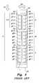
- FIG. 5is a plan view of a print head array of the pagewidth inkjet printer according to the present invention.
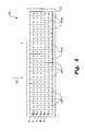
- FIG. 6is a plan view of an alternative embodiment of a print head array of the pagewidth inkjet printer according to the present invention.
- the pagewidth inkjet printer 10has a stationary array 16 of print heads 18 .
- pagewidth inkjet printer 20is shown as being in communication with a computer 88 in communication with a control circuit 140 , which utilizes a control pad 132 or the like, similar to printer 20 of FIG. 2 .
- the pagewidth inkjet printer 10may be used in combination with any suitable type of computer or other system for generating data to be printed on paper, and may include any suitable type of user interface.
- the elements of FIG. 1are shown for illustrative purposes only.
- the pagewidth inkjet printer 10includes a print head array 16 that spans the entire width of the sheet or page of paper P, and that remains stationary with respect to the paper P and the platen 26 .
- the print head array 16is at least partially contained within a housing 12 , which may be mounted adjacent platen the 26 by any suitable supports or mounts (it should be understood that supports 14 are shown for exemplary purposes only).
- the print head array 16includes a plurality of individual print heads 18 .
- Each print head 18has five separate nozzles for ejecting ink, the five nozzles being aligned in a direction parallel to the direction of the paper P's movement (indicated by directional arrow SS).
- the print heads 18are arrayed linearly along a direction orthogonal to the direction of the paper P's path; i.e., the print heads are placed next to each other to span the entire width of the page P.
- twenty-four such print heads 18are shown in the print head array 16 , although it should be understood that any desired number may be utilized.
- An increase in the number of print heads 18corresponds to an increase in printing resolution.
- each individual print head 18including the nozzles associated therewith, as well as the control elements for turning each nozzle on or off and for controlling the paper's movement, are similar to that of a conventional inkjet print head, such as those shown in U.S. Pat. Nos. 6,629,744 or in 6,443,555, each of which is hereby incorporated by reference in its entirety.
- a conventional inkjet print headsuch as those shown in U.S. Pat. Nos. 6,629,744 or in 6,443,555, each of which is hereby incorporated by reference in its entirety.
- each print head 18has a nozzle K for ejecting black ink, a nozzle C for ejecting cyan ink, a nozzle Y for ejecting yellow ink, a nozzle B for ejecting blue ink, and a nozzle P for ejecting pink ink.
- each print head 18is in fluid communication with a feeding ink tank or reservoir, such as reservoir 19 , diagrammatically shown in FIG. 1 .
- reservoir 19is shown for exemplary purposes, and any suitable number of chambers or any suitable number of separate reservoirs or tanks may be utilized, depending upon the number of different inks utilized.
- the housing 12 and the print head array 16are mounted above the platen 26 in a fixed and permanent manner, so that print head array 16 remains stationary with respect to platen 26 .
- the print head arrayis divided into a first row 13 and a second row 15 , each extending linearly in the direction orthogonal to direction SS.
- the individual print heads 18alternate between positioning in the first row and the second row and are staggered.
- the arrangement of print heads 18 in FIG. 6ensures that there are no gaps in printed images due to the low nozzle packing densities permitted by standard inkjet printers, and further allows for the production of larger print heads.
- the pagewidth inkjet printer 10allows for printing along a full horizontal strip all at once (i.e., each individual print head 18 may operate at the same time as the other print heads 18 in array 16 , thus allowing for printing along the entire width of the page P simultaneously), thus greatly enhancing speed of printing as compared to a conventional inkjet printer.
- a control circuitis operable to selectively turn the nozzles of each print head 18 on and off so that each stationary print head 18 prints only the portion of a horizontal line of print corresponding to the horizontal portion of the page that passes below the print head 18 , the print heads 18 printing simultaneously to print each portion of the horizontal line of print simultaneously.
- FIGS. 5 and 6illustrate each print head 18 having nozzles K, C, Y, B and P, it should be understood that any desired number of nozzles may be used, for example, to increase the number of colors of ink that may be ejected therefrom, and to provide any desired combination of colors. Cyan, yellow, blue and pink have been used herein for exemplary purposes only.
Landscapes
- Ink Jet (AREA)
Abstract
Description
Claims (10)
Priority Applications (1)
| Application Number | Priority Date | Filing Date | Title |
|---|---|---|---|
| US12/897,666US8348387B2 (en) | 2007-11-26 | 2010-10-04 | Pagewidth inkjet printer with multiple aligned print heads |
Applications Claiming Priority (2)
| Application Number | Priority Date | Filing Date | Title |
|---|---|---|---|
| US11/944,737US20090135235A1 (en) | 2007-11-26 | 2007-11-26 | Pagewidth Inkjet Printer with Multiple Print head arrangement |
| US12/897,666US8348387B2 (en) | 2007-11-26 | 2010-10-04 | Pagewidth inkjet printer with multiple aligned print heads |
Related Parent Applications (1)
| Application Number | Title | Priority Date | Filing Date |
|---|---|---|---|
| US11/944,737Continuation-In-PartUS20090135235A1 (en) | 2007-11-26 | 2007-11-26 | Pagewidth Inkjet Printer with Multiple Print head arrangement |
Publications (2)
| Publication Number | Publication Date |
|---|---|
| US20110018932A1 US20110018932A1 (en) | 2011-01-27 |
| US8348387B2true US8348387B2 (en) | 2013-01-08 |
Family
ID=43496913
Family Applications (1)
| Application Number | Title | Priority Date | Filing Date |
|---|---|---|---|
| US12/897,666Expired - Fee RelatedUS8348387B2 (en) | 2007-11-26 | 2010-10-04 | Pagewidth inkjet printer with multiple aligned print heads |
Country Status (1)
| Country | Link |
|---|---|
| US (1) | US8348387B2 (en) |
Families Citing this family (1)
| Publication number | Priority date | Publication date | Assignee | Title |
|---|---|---|---|---|
| JP6260108B2 (en)* | 2013-05-15 | 2018-01-17 | 株式会社リコー | Manufacturing method of electronic device |
Citations (9)
| Publication number | Priority date | Publication date | Assignee | Title |
|---|---|---|---|---|
| US6443555B1 (en) | 1999-03-16 | 2002-09-03 | Silverbrook Research Pty Ltd | Pagewidth wide format printer |
| US6450605B1 (en) | 1998-11-09 | 2002-09-17 | Silverbrook Res Pty Ltd | Modular printhead and methods of loading and printing using it |
| US6629744B2 (en) | 2001-05-23 | 2003-10-07 | Seiko Epson Corporation | Printing by switching sub-scan feeding between monochromatic and color areas |
| US6637860B1 (en)* | 2002-05-13 | 2003-10-28 | Creo Srl | High throughput inkjet printer with provision for spot color printing |
| US20030214554A1 (en) | 2002-05-14 | 2003-11-20 | Wellspring Trust | High-speed, high-resolution color printing apparatus and method |
| US6672717B2 (en) | 2001-11-13 | 2004-01-06 | Xerox Corporation | Ink jet printing with inks containing cationic-anionic monomer pairs |
| US7264324B2 (en) | 2004-12-17 | 2007-09-04 | Xerox Corporation | Method and apparatus with vernier technique for registration of ejector module |
| US7350899B2 (en) | 2004-01-19 | 2008-04-01 | Seiko Epson Corporation | Discharge apparatus, material application method, manufacturing method for color filter substrate, manufacturing method for electroluminescence display apparatus, manufacturing method for plasma display apparatus, and wiring manufacturing method |
| US7735948B2 (en) | 2004-05-27 | 2010-06-15 | Silverbrook Research Pty Ltd | Printhead having grouped nozzle firing |
- 2010
- 2010-10-04USUS12/897,666patent/US8348387B2/ennot_activeExpired - Fee Related
Patent Citations (9)
| Publication number | Priority date | Publication date | Assignee | Title |
|---|---|---|---|---|
| US6450605B1 (en) | 1998-11-09 | 2002-09-17 | Silverbrook Res Pty Ltd | Modular printhead and methods of loading and printing using it |
| US6443555B1 (en) | 1999-03-16 | 2002-09-03 | Silverbrook Research Pty Ltd | Pagewidth wide format printer |
| US6629744B2 (en) | 2001-05-23 | 2003-10-07 | Seiko Epson Corporation | Printing by switching sub-scan feeding between monochromatic and color areas |
| US6672717B2 (en) | 2001-11-13 | 2004-01-06 | Xerox Corporation | Ink jet printing with inks containing cationic-anionic monomer pairs |
| US6637860B1 (en)* | 2002-05-13 | 2003-10-28 | Creo Srl | High throughput inkjet printer with provision for spot color printing |
| US20030214554A1 (en) | 2002-05-14 | 2003-11-20 | Wellspring Trust | High-speed, high-resolution color printing apparatus and method |
| US7350899B2 (en) | 2004-01-19 | 2008-04-01 | Seiko Epson Corporation | Discharge apparatus, material application method, manufacturing method for color filter substrate, manufacturing method for electroluminescence display apparatus, manufacturing method for plasma display apparatus, and wiring manufacturing method |
| US7735948B2 (en) | 2004-05-27 | 2010-06-15 | Silverbrook Research Pty Ltd | Printhead having grouped nozzle firing |
| US7264324B2 (en) | 2004-12-17 | 2007-09-04 | Xerox Corporation | Method and apparatus with vernier technique for registration of ejector module |
Also Published As
| Publication number | Publication date |
|---|---|
| US20110018932A1 (en) | 2011-01-27 |
Similar Documents
| Publication | Publication Date | Title |
|---|---|---|
| EP0863004B2 (en) | Dynamic multi-pass print mode corrections to compensate for malfunctioning inkjet nozzles | |
| US6764154B2 (en) | Ink-jet printing apparatus and ink-jet printing method | |
| EP0748693B1 (en) | Thermal ink jet printhead with extended print capability | |
| JP3305182B2 (en) | Serial recording device | |
| EP0983855A2 (en) | Dot substitution to compensate for failed ink jet nozzles | |
| US6267468B1 (en) | Printhead substrate having a mixture of single and double sided elongate ink feed channels | |
| JPH02204053A (en) | Ink jet typing device enabling changeover of two ink | |
| US20090128594A1 (en) | Defective nozzle replacement in a printer | |
| KR19990088039A (en) | Bi-directional printing with controlled hue shifts | |
| JP2002264319A5 (en) | ||
| US6315389B1 (en) | Printhead having different center to center spacings between rows of nozzles | |
| US9033457B2 (en) | Print head and ink jet printing apparatus | |
| US8348387B2 (en) | Pagewidth inkjet printer with multiple aligned print heads | |
| US6106101A (en) | Print head assembly | |
| JP2009248501A (en) | Ink jet recording device | |
| JP5316112B2 (en) | Image forming apparatus | |
| TWI546200B (en) | Ink-jet printing module | |
| JP2007007899A (en) | Printing apparatus, printing method, and image processing method | |
| US6793304B2 (en) | Printing apparatus | |
| EP1145854A2 (en) | A printhead substrate having ink drop generators arranged in groups that span both edges of an ink feed channel | |
| JP4259965B2 (en) | Image forming apparatus | |
| EP0775586A1 (en) | Inkjet print carriage width minimization | |
| US20080150990A1 (en) | Ink jet printing apparatus and ink absorber recovery method | |
| JP2010184442A (en) | Recording device and recording control method | |
| JP2008173835A (en) | Liquid ejection device |
Legal Events
| Date | Code | Title | Description |
|---|---|---|---|
| AS | Assignment | Owner name:KUWAIT UNIVERSITY, KUWAIT Free format text:ASSIGNMENT OF ASSIGNORS INTEREST;ASSIGNOR:ALBAHRI, TAREQ ABDULJALIL, DR.;REEL/FRAME:025089/0097 Effective date:20100811 | |
| REMI | Maintenance fee reminder mailed | ||
| FEPP | Fee payment procedure | Free format text:PETITION RELATED TO MAINTENANCE FEES GRANTED (ORIGINAL EVENT CODE: PMFG); ENTITY STATUS OF PATENT OWNER: SMALL ENTITY Free format text:PETITION RELATED TO MAINTENANCE FEES FILED (ORIGINAL EVENT CODE: PMFP); ENTITY STATUS OF PATENT OWNER: SMALL ENTITY | |
| LAPS | Lapse for failure to pay maintenance fees | ||
| REIN | Reinstatement after maintenance fee payment confirmed | ||
| FP | Lapsed due to failure to pay maintenance fee | Effective date:20170108 | |
| PRDP | Patent reinstated due to the acceptance of a late maintenance fee | Effective date:20170713 | |
| FPAY | Fee payment | Year of fee payment:4 | |
| STCF | Information on status: patent grant | Free format text:PATENTED CASE | |
| SULP | Surcharge for late payment | ||
| FEPP | Fee payment procedure | Free format text:MAINTENANCE FEE REMINDER MAILED (ORIGINAL EVENT CODE: REM.); ENTITY STATUS OF PATENT OWNER: SMALL ENTITY | |
| LAPS | Lapse for failure to pay maintenance fees | Free format text:PATENT EXPIRED FOR FAILURE TO PAY MAINTENANCE FEES (ORIGINAL EVENT CODE: EXP.); ENTITY STATUS OF PATENT OWNER: SMALL ENTITY | |
| STCH | Information on status: patent discontinuation | Free format text:PATENT EXPIRED DUE TO NONPAYMENT OF MAINTENANCE FEES UNDER 37 CFR 1.362 | |
| FP | Lapsed due to failure to pay maintenance fee | Effective date:20210108 |