US8346416B2 - Method, apparatus, signals and media, for selecting operating conditions of a genset - Google Patents
Method, apparatus, signals and media, for selecting operating conditions of a gensetDownload PDFInfo
- Publication number
- US8346416B2 US8346416B2US11/821,855US82185507AUS8346416B2US 8346416 B2US8346416 B2US 8346416B2US 82185507 AUS82185507 AUS 82185507AUS 8346416 B2US8346416 B2US 8346416B2
- Authority
- US
- United States
- Prior art keywords
- genset
- power output
- operating points
- operating
- values
- Prior art date
- Legal status (The legal status is an assumption and is not a legal conclusion. Google has not performed a legal analysis and makes no representation as to the accuracy of the status listed.)
- Active, expires
Links
Images


Classifications
- B—PERFORMING OPERATIONS; TRANSPORTING
- B60—VEHICLES IN GENERAL
- B60W—CONJOINT CONTROL OF VEHICLE SUB-UNITS OF DIFFERENT TYPE OR DIFFERENT FUNCTION; CONTROL SYSTEMS SPECIALLY ADAPTED FOR HYBRID VEHICLES; ROAD VEHICLE DRIVE CONTROL SYSTEMS FOR PURPOSES NOT RELATED TO THE CONTROL OF A PARTICULAR SUB-UNIT
- B60W20/00—Control systems specially adapted for hybrid vehicles
- B60W20/10—Controlling the power contribution of each of the prime movers to meet required power demand
- B60W20/11—Controlling the power contribution of each of the prime movers to meet required power demand using model predictive control [MPC] strategies, i.e. control methods based on models predicting performance
- B—PERFORMING OPERATIONS; TRANSPORTING
- B60—VEHICLES IN GENERAL
- B60K—ARRANGEMENT OR MOUNTING OF PROPULSION UNITS OR OF TRANSMISSIONS IN VEHICLES; ARRANGEMENT OR MOUNTING OF PLURAL DIVERSE PRIME-MOVERS IN VEHICLES; AUXILIARY DRIVES FOR VEHICLES; INSTRUMENTATION OR DASHBOARDS FOR VEHICLES; ARRANGEMENTS IN CONNECTION WITH COOLING, AIR INTAKE, GAS EXHAUST OR FUEL SUPPLY OF PROPULSION UNITS IN VEHICLES
- B60K6/00—Arrangement or mounting of plural diverse prime-movers for mutual or common propulsion, e.g. hybrid propulsion systems comprising electric motors and internal combustion engines
- B60K6/20—Arrangement or mounting of plural diverse prime-movers for mutual or common propulsion, e.g. hybrid propulsion systems comprising electric motors and internal combustion engines the prime-movers consisting of electric motors and internal combustion engines, e.g. HEVs
- B60K6/42—Arrangement or mounting of plural diverse prime-movers for mutual or common propulsion, e.g. hybrid propulsion systems comprising electric motors and internal combustion engines the prime-movers consisting of electric motors and internal combustion engines, e.g. HEVs characterised by the architecture of the hybrid electric vehicle
- B60K6/48—Parallel type
- B—PERFORMING OPERATIONS; TRANSPORTING
- B60—VEHICLES IN GENERAL
- B60L—PROPULSION OF ELECTRICALLY-PROPELLED VEHICLES; SUPPLYING ELECTRIC POWER FOR AUXILIARY EQUIPMENT OF ELECTRICALLY-PROPELLED VEHICLES; ELECTRODYNAMIC BRAKE SYSTEMS FOR VEHICLES IN GENERAL; MAGNETIC SUSPENSION OR LEVITATION FOR VEHICLES; MONITORING OPERATING VARIABLES OF ELECTRICALLY-PROPELLED VEHICLES; ELECTRIC SAFETY DEVICES FOR ELECTRICALLY-PROPELLED VEHICLES
- B60L1/00—Supplying electric power to auxiliary equipment of vehicles
- B60L1/003—Supplying electric power to auxiliary equipment of vehicles to auxiliary motors, e.g. for pumps, compressors
- B—PERFORMING OPERATIONS; TRANSPORTING
- B60—VEHICLES IN GENERAL
- B60L—PROPULSION OF ELECTRICALLY-PROPELLED VEHICLES; SUPPLYING ELECTRIC POWER FOR AUXILIARY EQUIPMENT OF ELECTRICALLY-PROPELLED VEHICLES; ELECTRODYNAMIC BRAKE SYSTEMS FOR VEHICLES IN GENERAL; MAGNETIC SUSPENSION OR LEVITATION FOR VEHICLES; MONITORING OPERATING VARIABLES OF ELECTRICALLY-PROPELLED VEHICLES; ELECTRIC SAFETY DEVICES FOR ELECTRICALLY-PROPELLED VEHICLES
- B60L1/00—Supplying electric power to auxiliary equipment of vehicles
- B60L1/02—Supplying electric power to auxiliary equipment of vehicles to electric heating circuits
- B—PERFORMING OPERATIONS; TRANSPORTING
- B60—VEHICLES IN GENERAL
- B60L—PROPULSION OF ELECTRICALLY-PROPELLED VEHICLES; SUPPLYING ELECTRIC POWER FOR AUXILIARY EQUIPMENT OF ELECTRICALLY-PROPELLED VEHICLES; ELECTRODYNAMIC BRAKE SYSTEMS FOR VEHICLES IN GENERAL; MAGNETIC SUSPENSION OR LEVITATION FOR VEHICLES; MONITORING OPERATING VARIABLES OF ELECTRICALLY-PROPELLED VEHICLES; ELECTRIC SAFETY DEVICES FOR ELECTRICALLY-PROPELLED VEHICLES
- B60L15/00—Methods, circuits, or devices for controlling the traction-motor speed of electrically-propelled vehicles
- B60L15/20—Methods, circuits, or devices for controlling the traction-motor speed of electrically-propelled vehicles for control of the vehicle or its driving motor to achieve a desired performance, e.g. speed, torque, programmed variation of speed
- B60L15/2045—Methods, circuits, or devices for controlling the traction-motor speed of electrically-propelled vehicles for control of the vehicle or its driving motor to achieve a desired performance, e.g. speed, torque, programmed variation of speed for optimising the use of energy
- B—PERFORMING OPERATIONS; TRANSPORTING
- B60—VEHICLES IN GENERAL
- B60L—PROPULSION OF ELECTRICALLY-PROPELLED VEHICLES; SUPPLYING ELECTRIC POWER FOR AUXILIARY EQUIPMENT OF ELECTRICALLY-PROPELLED VEHICLES; ELECTRODYNAMIC BRAKE SYSTEMS FOR VEHICLES IN GENERAL; MAGNETIC SUSPENSION OR LEVITATION FOR VEHICLES; MONITORING OPERATING VARIABLES OF ELECTRICALLY-PROPELLED VEHICLES; ELECTRIC SAFETY DEVICES FOR ELECTRICALLY-PROPELLED VEHICLES
- B60L3/00—Electric devices on electrically-propelled vehicles for safety purposes; Monitoring operating variables, e.g. speed, deceleration or energy consumption
- B60L3/0023—Detecting, eliminating, remedying or compensating for drive train abnormalities, e.g. failures within the drive train
- B—PERFORMING OPERATIONS; TRANSPORTING
- B60—VEHICLES IN GENERAL
- B60L—PROPULSION OF ELECTRICALLY-PROPELLED VEHICLES; SUPPLYING ELECTRIC POWER FOR AUXILIARY EQUIPMENT OF ELECTRICALLY-PROPELLED VEHICLES; ELECTRODYNAMIC BRAKE SYSTEMS FOR VEHICLES IN GENERAL; MAGNETIC SUSPENSION OR LEVITATION FOR VEHICLES; MONITORING OPERATING VARIABLES OF ELECTRICALLY-PROPELLED VEHICLES; ELECTRIC SAFETY DEVICES FOR ELECTRICALLY-PROPELLED VEHICLES
- B60L50/00—Electric propulsion with power supplied within the vehicle
- B60L50/10—Electric propulsion with power supplied within the vehicle using propulsion power supplied by engine-driven generators, e.g. generators driven by combustion engines
- B—PERFORMING OPERATIONS; TRANSPORTING
- B60—VEHICLES IN GENERAL
- B60L—PROPULSION OF ELECTRICALLY-PROPELLED VEHICLES; SUPPLYING ELECTRIC POWER FOR AUXILIARY EQUIPMENT OF ELECTRICALLY-PROPELLED VEHICLES; ELECTRODYNAMIC BRAKE SYSTEMS FOR VEHICLES IN GENERAL; MAGNETIC SUSPENSION OR LEVITATION FOR VEHICLES; MONITORING OPERATING VARIABLES OF ELECTRICALLY-PROPELLED VEHICLES; ELECTRIC SAFETY DEVICES FOR ELECTRICALLY-PROPELLED VEHICLES
- B60L50/00—Electric propulsion with power supplied within the vehicle
- B60L50/30—Electric propulsion with power supplied within the vehicle using propulsion power stored mechanically, e.g. in fly-wheels
- B—PERFORMING OPERATIONS; TRANSPORTING
- B60—VEHICLES IN GENERAL
- B60L—PROPULSION OF ELECTRICALLY-PROPELLED VEHICLES; SUPPLYING ELECTRIC POWER FOR AUXILIARY EQUIPMENT OF ELECTRICALLY-PROPELLED VEHICLES; ELECTRODYNAMIC BRAKE SYSTEMS FOR VEHICLES IN GENERAL; MAGNETIC SUSPENSION OR LEVITATION FOR VEHICLES; MONITORING OPERATING VARIABLES OF ELECTRICALLY-PROPELLED VEHICLES; ELECTRIC SAFETY DEVICES FOR ELECTRICALLY-PROPELLED VEHICLES
- B60L50/00—Electric propulsion with power supplied within the vehicle
- B60L50/40—Electric propulsion with power supplied within the vehicle using propulsion power supplied by capacitors
- B—PERFORMING OPERATIONS; TRANSPORTING
- B60—VEHICLES IN GENERAL
- B60L—PROPULSION OF ELECTRICALLY-PROPELLED VEHICLES; SUPPLYING ELECTRIC POWER FOR AUXILIARY EQUIPMENT OF ELECTRICALLY-PROPELLED VEHICLES; ELECTRODYNAMIC BRAKE SYSTEMS FOR VEHICLES IN GENERAL; MAGNETIC SUSPENSION OR LEVITATION FOR VEHICLES; MONITORING OPERATING VARIABLES OF ELECTRICALLY-PROPELLED VEHICLES; ELECTRIC SAFETY DEVICES FOR ELECTRICALLY-PROPELLED VEHICLES
- B60L50/00—Electric propulsion with power supplied within the vehicle
- B60L50/50—Electric propulsion with power supplied within the vehicle using propulsion power supplied by batteries or fuel cells
- B60L50/60—Electric propulsion with power supplied within the vehicle using propulsion power supplied by batteries or fuel cells using power supplied by batteries
- B60L50/61—Electric propulsion with power supplied within the vehicle using propulsion power supplied by batteries or fuel cells using power supplied by batteries by batteries charged by engine-driven generators, e.g. series hybrid electric vehicles
- B60L50/62—Electric propulsion with power supplied within the vehicle using propulsion power supplied by batteries or fuel cells using power supplied by batteries by batteries charged by engine-driven generators, e.g. series hybrid electric vehicles charged by low-power generators primarily intended to support the batteries, e.g. range extenders
- B—PERFORMING OPERATIONS; TRANSPORTING
- B60—VEHICLES IN GENERAL
- B60W—CONJOINT CONTROL OF VEHICLE SUB-UNITS OF DIFFERENT TYPE OR DIFFERENT FUNCTION; CONTROL SYSTEMS SPECIALLY ADAPTED FOR HYBRID VEHICLES; ROAD VEHICLE DRIVE CONTROL SYSTEMS FOR PURPOSES NOT RELATED TO THE CONTROL OF A PARTICULAR SUB-UNIT
- B60W10/00—Conjoint control of vehicle sub-units of different type or different function
- B60W10/04—Conjoint control of vehicle sub-units of different type or different function including control of propulsion units
- B60W10/06—Conjoint control of vehicle sub-units of different type or different function including control of propulsion units including control of combustion engines
- B—PERFORMING OPERATIONS; TRANSPORTING
- B60—VEHICLES IN GENERAL
- B60W—CONJOINT CONTROL OF VEHICLE SUB-UNITS OF DIFFERENT TYPE OR DIFFERENT FUNCTION; CONTROL SYSTEMS SPECIALLY ADAPTED FOR HYBRID VEHICLES; ROAD VEHICLE DRIVE CONTROL SYSTEMS FOR PURPOSES NOT RELATED TO THE CONTROL OF A PARTICULAR SUB-UNIT
- B60W10/00—Conjoint control of vehicle sub-units of different type or different function
- B60W10/04—Conjoint control of vehicle sub-units of different type or different function including control of propulsion units
- B60W10/08—Conjoint control of vehicle sub-units of different type or different function including control of propulsion units including control of electric propulsion units, e.g. motors or generators
- B—PERFORMING OPERATIONS; TRANSPORTING
- B60—VEHICLES IN GENERAL
- B60W—CONJOINT CONTROL OF VEHICLE SUB-UNITS OF DIFFERENT TYPE OR DIFFERENT FUNCTION; CONTROL SYSTEMS SPECIALLY ADAPTED FOR HYBRID VEHICLES; ROAD VEHICLE DRIVE CONTROL SYSTEMS FOR PURPOSES NOT RELATED TO THE CONTROL OF A PARTICULAR SUB-UNIT
- B60W10/00—Conjoint control of vehicle sub-units of different type or different function
- B60W10/24—Conjoint control of vehicle sub-units of different type or different function including control of energy storage means
- B—PERFORMING OPERATIONS; TRANSPORTING
- B60—VEHICLES IN GENERAL
- B60W—CONJOINT CONTROL OF VEHICLE SUB-UNITS OF DIFFERENT TYPE OR DIFFERENT FUNCTION; CONTROL SYSTEMS SPECIALLY ADAPTED FOR HYBRID VEHICLES; ROAD VEHICLE DRIVE CONTROL SYSTEMS FOR PURPOSES NOT RELATED TO THE CONTROL OF A PARTICULAR SUB-UNIT
- B60W20/00—Control systems specially adapted for hybrid vehicles
- B60W20/10—Controlling the power contribution of each of the prime movers to meet required power demand
- B60W20/15—Control strategies specially adapted for achieving a particular effect
- B60W20/16—Control strategies specially adapted for achieving a particular effect for reducing engine exhaust emissions
- F—MECHANICAL ENGINEERING; LIGHTING; HEATING; WEAPONS; BLASTING
- F01—MACHINES OR ENGINES IN GENERAL; ENGINE PLANTS IN GENERAL; STEAM ENGINES
- F01N—GAS-FLOW SILENCERS OR EXHAUST APPARATUS FOR MACHINES OR ENGINES IN GENERAL; GAS-FLOW SILENCERS OR EXHAUST APPARATUS FOR INTERNAL-COMBUSTION ENGINES
- F01N11/00—Monitoring or diagnostic devices for exhaust-gas treatment apparatus
- G—PHYSICS
- G01—MEASURING; TESTING
- G01F—MEASURING VOLUME, VOLUME FLOW, MASS FLOW OR LIQUID LEVEL; METERING BY VOLUME
- G01F13/00—Apparatus for measuring by volume and delivering fluids or fluent solid materials, not provided for in the preceding groups
- G—PHYSICS
- G01—MEASURING; TESTING
- G01N—INVESTIGATING OR ANALYSING MATERIALS BY DETERMINING THEIR CHEMICAL OR PHYSICAL PROPERTIES
- G01N19/00—Investigating materials by mechanical methods
- G—PHYSICS
- G06—COMPUTING OR CALCULATING; COUNTING
- G06F—ELECTRIC DIGITAL DATA PROCESSING
- G06F15/00—Digital computers in general; Data processing equipment in general
- H—ELECTRICITY
- H02—GENERATION; CONVERSION OR DISTRIBUTION OF ELECTRIC POWER
- H02P—CONTROL OR REGULATION OF ELECTRIC MOTORS, ELECTRIC GENERATORS OR DYNAMO-ELECTRIC CONVERTERS; CONTROLLING TRANSFORMERS, REACTORS OR CHOKE COILS
- H02P9/00—Arrangements for controlling electric generators for the purpose of obtaining a desired output
- H02P9/04—Control effected upon non-electric prime mover and dependent upon electric output value of the generator
- B—PERFORMING OPERATIONS; TRANSPORTING
- B60—VEHICLES IN GENERAL
- B60L—PROPULSION OF ELECTRICALLY-PROPELLED VEHICLES; SUPPLYING ELECTRIC POWER FOR AUXILIARY EQUIPMENT OF ELECTRICALLY-PROPELLED VEHICLES; ELECTRODYNAMIC BRAKE SYSTEMS FOR VEHICLES IN GENERAL; MAGNETIC SUSPENSION OR LEVITATION FOR VEHICLES; MONITORING OPERATING VARIABLES OF ELECTRICALLY-PROPELLED VEHICLES; ELECTRIC SAFETY DEVICES FOR ELECTRICALLY-PROPELLED VEHICLES
- B60L2240/00—Control parameters of input or output; Target parameters
- B60L2240/10—Vehicle control parameters
- B60L2240/36—Temperature of vehicle components or parts
- B—PERFORMING OPERATIONS; TRANSPORTING
- B60—VEHICLES IN GENERAL
- B60L—PROPULSION OF ELECTRICALLY-PROPELLED VEHICLES; SUPPLYING ELECTRIC POWER FOR AUXILIARY EQUIPMENT OF ELECTRICALLY-PROPELLED VEHICLES; ELECTRODYNAMIC BRAKE SYSTEMS FOR VEHICLES IN GENERAL; MAGNETIC SUSPENSION OR LEVITATION FOR VEHICLES; MONITORING OPERATING VARIABLES OF ELECTRICALLY-PROPELLED VEHICLES; ELECTRIC SAFETY DEVICES FOR ELECTRICALLY-PROPELLED VEHICLES
- B60L2240/00—Control parameters of input or output; Target parameters
- B60L2240/40—Drive Train control parameters
- B60L2240/42—Drive Train control parameters related to electric machines
- B60L2240/421—Speed
- B—PERFORMING OPERATIONS; TRANSPORTING
- B60—VEHICLES IN GENERAL
- B60L—PROPULSION OF ELECTRICALLY-PROPELLED VEHICLES; SUPPLYING ELECTRIC POWER FOR AUXILIARY EQUIPMENT OF ELECTRICALLY-PROPELLED VEHICLES; ELECTRODYNAMIC BRAKE SYSTEMS FOR VEHICLES IN GENERAL; MAGNETIC SUSPENSION OR LEVITATION FOR VEHICLES; MONITORING OPERATING VARIABLES OF ELECTRICALLY-PROPELLED VEHICLES; ELECTRIC SAFETY DEVICES FOR ELECTRICALLY-PROPELLED VEHICLES
- B60L2240/00—Control parameters of input or output; Target parameters
- B60L2240/40—Drive Train control parameters
- B60L2240/44—Drive Train control parameters related to combustion engines
- B60L2240/441—Speed
- B—PERFORMING OPERATIONS; TRANSPORTING
- B60—VEHICLES IN GENERAL
- B60W—CONJOINT CONTROL OF VEHICLE SUB-UNITS OF DIFFERENT TYPE OR DIFFERENT FUNCTION; CONTROL SYSTEMS SPECIALLY ADAPTED FOR HYBRID VEHICLES; ROAD VEHICLE DRIVE CONTROL SYSTEMS FOR PURPOSES NOT RELATED TO THE CONTROL OF A PARTICULAR SUB-UNIT
- B60W20/00—Control systems specially adapted for hybrid vehicles
- B—PERFORMING OPERATIONS; TRANSPORTING
- B60—VEHICLES IN GENERAL
- B60W—CONJOINT CONTROL OF VEHICLE SUB-UNITS OF DIFFERENT TYPE OR DIFFERENT FUNCTION; CONTROL SYSTEMS SPECIALLY ADAPTED FOR HYBRID VEHICLES; ROAD VEHICLE DRIVE CONTROL SYSTEMS FOR PURPOSES NOT RELATED TO THE CONTROL OF A PARTICULAR SUB-UNIT
- B60W2510/00—Input parameters relating to a particular sub-units
- B60W2510/06—Combustion engines, Gas turbines
- B—PERFORMING OPERATIONS; TRANSPORTING
- B60—VEHICLES IN GENERAL
- B60W—CONJOINT CONTROL OF VEHICLE SUB-UNITS OF DIFFERENT TYPE OR DIFFERENT FUNCTION; CONTROL SYSTEMS SPECIALLY ADAPTED FOR HYBRID VEHICLES; ROAD VEHICLE DRIVE CONTROL SYSTEMS FOR PURPOSES NOT RELATED TO THE CONTROL OF A PARTICULAR SUB-UNIT
- B60W2556/00—Input parameters relating to data
- B60W2556/10—Historical data
- Y—GENERAL TAGGING OF NEW TECHNOLOGICAL DEVELOPMENTS; GENERAL TAGGING OF CROSS-SECTIONAL TECHNOLOGIES SPANNING OVER SEVERAL SECTIONS OF THE IPC; TECHNICAL SUBJECTS COVERED BY FORMER USPC CROSS-REFERENCE ART COLLECTIONS [XRACs] AND DIGESTS
- Y02—TECHNOLOGIES OR APPLICATIONS FOR MITIGATION OR ADAPTATION AGAINST CLIMATE CHANGE
- Y02T—CLIMATE CHANGE MITIGATION TECHNOLOGIES RELATED TO TRANSPORTATION
- Y02T10/00—Road transport of goods or passengers
- Y02T10/10—Internal combustion engine [ICE] based vehicles
- Y02T10/40—Engine management systems
- Y—GENERAL TAGGING OF NEW TECHNOLOGICAL DEVELOPMENTS; GENERAL TAGGING OF CROSS-SECTIONAL TECHNOLOGIES SPANNING OVER SEVERAL SECTIONS OF THE IPC; TECHNICAL SUBJECTS COVERED BY FORMER USPC CROSS-REFERENCE ART COLLECTIONS [XRACs] AND DIGESTS
- Y02—TECHNOLOGIES OR APPLICATIONS FOR MITIGATION OR ADAPTATION AGAINST CLIMATE CHANGE
- Y02T—CLIMATE CHANGE MITIGATION TECHNOLOGIES RELATED TO TRANSPORTATION
- Y02T10/00—Road transport of goods or passengers
- Y02T10/60—Other road transportation technologies with climate change mitigation effect
- Y02T10/62—Hybrid vehicles
- Y—GENERAL TAGGING OF NEW TECHNOLOGICAL DEVELOPMENTS; GENERAL TAGGING OF CROSS-SECTIONAL TECHNOLOGIES SPANNING OVER SEVERAL SECTIONS OF THE IPC; TECHNICAL SUBJECTS COVERED BY FORMER USPC CROSS-REFERENCE ART COLLECTIONS [XRACs] AND DIGESTS
- Y02—TECHNOLOGIES OR APPLICATIONS FOR MITIGATION OR ADAPTATION AGAINST CLIMATE CHANGE
- Y02T—CLIMATE CHANGE MITIGATION TECHNOLOGIES RELATED TO TRANSPORTATION
- Y02T10/00—Road transport of goods or passengers
- Y02T10/60—Other road transportation technologies with climate change mitigation effect
- Y02T10/64—Electric machine technologies in electromobility
- Y—GENERAL TAGGING OF NEW TECHNOLOGICAL DEVELOPMENTS; GENERAL TAGGING OF CROSS-SECTIONAL TECHNOLOGIES SPANNING OVER SEVERAL SECTIONS OF THE IPC; TECHNICAL SUBJECTS COVERED BY FORMER USPC CROSS-REFERENCE ART COLLECTIONS [XRACs] AND DIGESTS
- Y02—TECHNOLOGIES OR APPLICATIONS FOR MITIGATION OR ADAPTATION AGAINST CLIMATE CHANGE
- Y02T—CLIMATE CHANGE MITIGATION TECHNOLOGIES RELATED TO TRANSPORTATION
- Y02T10/00—Road transport of goods or passengers
- Y02T10/60—Other road transportation technologies with climate change mitigation effect
- Y02T10/70—Energy storage systems for electromobility, e.g. batteries
- Y—GENERAL TAGGING OF NEW TECHNOLOGICAL DEVELOPMENTS; GENERAL TAGGING OF CROSS-SECTIONAL TECHNOLOGIES SPANNING OVER SEVERAL SECTIONS OF THE IPC; TECHNICAL SUBJECTS COVERED BY FORMER USPC CROSS-REFERENCE ART COLLECTIONS [XRACs] AND DIGESTS
- Y02—TECHNOLOGIES OR APPLICATIONS FOR MITIGATION OR ADAPTATION AGAINST CLIMATE CHANGE
- Y02T—CLIMATE CHANGE MITIGATION TECHNOLOGIES RELATED TO TRANSPORTATION
- Y02T10/00—Road transport of goods or passengers
- Y02T10/60—Other road transportation technologies with climate change mitigation effect
- Y02T10/7072—Electromobility specific charging systems or methods for batteries, ultracapacitors, supercapacitors or double-layer capacitors
- Y—GENERAL TAGGING OF NEW TECHNOLOGICAL DEVELOPMENTS; GENERAL TAGGING OF CROSS-SECTIONAL TECHNOLOGIES SPANNING OVER SEVERAL SECTIONS OF THE IPC; TECHNICAL SUBJECTS COVERED BY FORMER USPC CROSS-REFERENCE ART COLLECTIONS [XRACs] AND DIGESTS
- Y02—TECHNOLOGIES OR APPLICATIONS FOR MITIGATION OR ADAPTATION AGAINST CLIMATE CHANGE
- Y02T—CLIMATE CHANGE MITIGATION TECHNOLOGIES RELATED TO TRANSPORTATION
- Y02T10/00—Road transport of goods or passengers
- Y02T10/60—Other road transportation technologies with climate change mitigation effect
- Y02T10/72—Electric energy management in electromobility
- Y—GENERAL TAGGING OF NEW TECHNOLOGICAL DEVELOPMENTS; GENERAL TAGGING OF CROSS-SECTIONAL TECHNOLOGIES SPANNING OVER SEVERAL SECTIONS OF THE IPC; TECHNICAL SUBJECTS COVERED BY FORMER USPC CROSS-REFERENCE ART COLLECTIONS [XRACs] AND DIGESTS
- Y10—TECHNICAL SUBJECTS COVERED BY FORMER USPC
- Y10S—TECHNICAL SUBJECTS COVERED BY FORMER USPC CROSS-REFERENCE ART COLLECTIONS [XRACs] AND DIGESTS
- Y10S903/00—Hybrid electric vehicles, HEVS
- Y10S903/902—Prime movers comprising electrical and internal combustion motors
- Y10S903/903—Prime movers comprising electrical and internal combustion motors having energy storing means, e.g. battery, capacitor
- Y10S903/904—Component specially adapted for hev
- Y10S903/905—Combustion engine
- Y—GENERAL TAGGING OF NEW TECHNOLOGICAL DEVELOPMENTS; GENERAL TAGGING OF CROSS-SECTIONAL TECHNOLOGIES SPANNING OVER SEVERAL SECTIONS OF THE IPC; TECHNICAL SUBJECTS COVERED BY FORMER USPC CROSS-REFERENCE ART COLLECTIONS [XRACs] AND DIGESTS
- Y10—TECHNICAL SUBJECTS COVERED BY FORMER USPC
- Y10S—TECHNICAL SUBJECTS COVERED BY FORMER USPC CROSS-REFERENCE ART COLLECTIONS [XRACs] AND DIGESTS
- Y10S903/00—Hybrid electric vehicles, HEVS
- Y10S903/902—Prime movers comprising electrical and internal combustion motors
- Y10S903/903—Prime movers comprising electrical and internal combustion motors having energy storing means, e.g. battery, capacitor
- Y10S903/904—Component specially adapted for hev
- Y10S903/906—Motor or generator
- Y—GENERAL TAGGING OF NEW TECHNOLOGICAL DEVELOPMENTS; GENERAL TAGGING OF CROSS-SECTIONAL TECHNOLOGIES SPANNING OVER SEVERAL SECTIONS OF THE IPC; TECHNICAL SUBJECTS COVERED BY FORMER USPC CROSS-REFERENCE ART COLLECTIONS [XRACs] AND DIGESTS
- Y10—TECHNICAL SUBJECTS COVERED BY FORMER USPC
- Y10S—TECHNICAL SUBJECTS COVERED BY FORMER USPC CROSS-REFERENCE ART COLLECTIONS [XRACs] AND DIGESTS
- Y10S903/00—Hybrid electric vehicles, HEVS
- Y10S903/902—Prime movers comprising electrical and internal combustion motors
- Y10S903/903—Prime movers comprising electrical and internal combustion motors having energy storing means, e.g. battery, capacitor
- Y10S903/93—Conjoint control of different elements
Definitions
- This inventionrelates generally to selecting operating conditions of an engine coupled to an electrical power generator for generating electrical power.
- Hybrid vehicles having an engine driving a generatorcause emissions such as nitrogen oxides, carbon monoxide, hydrocarbons, and particulate matter.
- emissionssuch as nitrogen oxides, carbon monoxide, hydrocarbons, and particulate matter.
- Each emissionhas a characteristic dependence on a power output level of the generator, and a rotational speed of the engine.
- the gensetmay supply electrical power to a drive motor and/or a charger for charging a storage battery
- choosing operating points for the vehicle that minimize fuel consumption while simultaneously minimizing emissions or other operating conditionsis a multi-variable problem and selecting operating points for the genset usually involves trading off between various emissions and fuel consumption to meet a desired criterion.
- a method for selecting optimal operating conditions of a gensetincluding an engine coupled to an electrical power generator, the genset having a plurality of operating points each including an engine speed value and a generator electrical power output value, and having a plurality of cost values associated with operating the genset at respective operating points.
- the methodinvolves selecting a set of operating points from the plurality of operating points such that a sum of cost values associated with operating points in the set is minimized and such that the engine speed and generator electrical power output values of the operating points in the set increase or decrease monotonically.
- the methodmay involve assigning a weight to each of the power output values such that cost values corresponding to more frequently demanded power output values are assigned a greater weight in the sum of cost values than cost values corresponding to less frequently demanded electrical power output values.
- Assigning the weightmay involve assigning greater weight to electrical power output values proximate a midpoint of a range of power outputs that the generator is capable of supplying.
- the methodmay involve generating a record of received demands for power outputs during operation of the genset over a period of time, and assigning the weights may involve assigning greater weight to more frequently used power output values.
- Generating the recordmay involve generating the record and updating the weights while operating the genset, and selecting may involve selecting a new set of operating points when the weights have been updated.
- Selectingmay involve successively applying a dynamic programming algorithm to select sets of operating points at successive power output values within a range of power outputs the generator is capable of supplying, and selecting a set of operating points corresponding to a last power output value in the range as the minimized set of operating points for the genset.
- Applying the dynamic programming algorithmmay involve producing a first plurality of the sums of cost values at a first power output value and memoizing a result of at least one of the first plurality of the sums.
- the methodmay further involve using at least some of the memoized results for producing a further sum of cost values at a subsequent power output value.
- Selectingmay involve locating a minimum cost value at each power output value and successively applying the dynamic programming algorithm may involve first producing the sums of cost values corresponding to the minimum cost value at each successive power output value.
- Locating the minimum cost valuemay involve locating an operating point corresponding to the minimum cost value using a golden section search technique.
- the methodmay involve receiving a demand to supply power at a demanded power output value and operating the genset at an operating point in the set of operating points corresponding to the demanded power output value.
- the gensetmay be used to generate electrical energy for use in a hybrid electrical vehicle and receiving the demand may involve receiving a demand to supply power to at least one of a drive motor, a charger operable to charge a storage element, and an accessory associated with the hybrid vehicle.
- Receiving the demand to supply power to the chargermay involve receiving a demand to supply power to the charger while the hybrid electric vehicle remains stationary.
- Receiving the demand to supply power to the drive motormay involve receiving a drive signal from an operator foot pedal representing a desired drive power to be supplied by the drive motor to wheels of the hybrid vehicle.
- the storage elementmay be operable to supply at least a first portion of the desired drive power, and receiving the demand may involve receiving a demand for a second portion of the desired drive power.
- Receiving the demand to supply power to the chargermay involve receiving a charge signal from a storage element controller, the charge signal being produced in response to a state of charge associated with the storage element.
- the methodmay involve receiving a plurality of cost values.
- the methodmay involve selecting a new set of operating points in response to receiving the plurality of cost values.
- Selectingmay involve selecting the set of genset operating points prior to operating the genset.
- an apparatus for selecting operating conditions of a gensetincluding an engine coupled to an electrical power generator, the genset having a plurality of operating points each including an engine speed value and a generator electrical power output value, and having a plurality of cost values associated with operating the genset at respective operating points.
- the apparatusincludes provisions for selecting a set of operating points from the plurality of operating points such that a sum of cost values associated with operating points in the set is minimized and such that the engine speed and generator electrical power output values of the operating points in the set increase or decrease monotonically.
- the apparatusmay include provisions for assigning a weight to each of the power output values such that cost values corresponding to more frequently demanded power output values are assigned a greater weight in the sum of cost values than cost values corresponding to less frequently demanded electrical power output values.
- the provisions for assigning the weightmay include provisions for assigning greater weight to electrical power output values proximate a midpoint of a range of power output values that the generator is capable of supplying.
- the apparatusmay include provisions for generating a record of received demands for power outputs during operation of the genset over a period of time, and the provisions for assigning the weights may include provisions for assigning greater weight to more frequently used power output values.
- the provisions for generating the recordmay include provisions for updating the weights while operating the genset, and the provisions for selecting may be operably configured to select a new set of operating points when the weights have been updated.
- the provisions for selectingmay include provisions for successively applying a dynamic programming algorithm to select sets of operating points at successive power output values within a range of power outputs the generator is capable of supplying and provisions for selecting a set of operating points corresponding to a last power output value in the range as the minimized set of operating points for the genset.
- the provisions for applying the dynamic programming algorithmmay include provisions for producing a first plurality of the sums of cost values at a first power output value, provisions for memoizing a result of at least one of the first plurality of the sums, and provisions for using at least some of the memoized results for producing a further sum of cost values at a subsequent power output value.
- the provisions for selectingmay include provisions for locating a minimum cost value at each power output value and the provisions for successively applying the dynamic programming algorithm may include provisions for first producing the sums of cost values corresponding to the minimum cost value at each successive power output value.
- the provisions for locating the minimum cost valuemay include provisions for performing a golden section search technique.
- the apparatusmay include provisions for receiving a demand to supply power at a demanded power output value and provisions for operating the genset at an operating point in the set of operating points corresponding to the demanded power output value.
- the gensetmay be used to generate electrical energy for use in a hybrid electrical vehicle and the provisions for receiving the demand may include provisions for receiving a demand to supply power to at least one of a drive motor, a charger operable to charge a storage element, and an accessory associated with the hybrid vehicle.
- the provisions for receiving the demand to supply power to the chargermay include means for receiving a demand to supply power to the charger while the hybrid electric vehicle remains stationary.
- the storage elementmay include at least one of a storage battery, a capacitor, and an electrically coupled flywheel.
- the provisions for receiving the demand to supply power to the drive motormay include provisions for receiving a drive signal from an operator foot pedal representing a desired drive power to be supplied by the drive motor to wheels of the hybrid vehicle.
- the storage elementmay be operable to supply at least a first portion of the desired drive power, and the demand may include a demand for a second portion of the desired drive power.
- the provisions for receiving the demand to supply power to the chargermay include provisions for receiving a charge signal from a storage element controller, the charge signal being produced in response to a state of charge associated with the storage element.
- the apparatusmay include provisions for receiving a plurality of cost values.
- the apparatusmay include provisions for selecting a new set of operating points in response to receiving the plurality of cost values.
- the provisions for selectingmay include provisions for selecting the set of genset operating points prior to operating the genset.
- an apparatus for selecting operating conditions of a gensetincluding an engine coupled to an electrical power generator, the genset having a plurality of operating points each including an engine speed value and a generator electrical power output value, and having a plurality of cost values associated with operating the genset at respective operating points.
- the apparatusincludes a processor circuit operable to select a set of operating points from the plurality of operating points such that a sum of cost values associated with operating points in the set is minimized and such that the engine speed and generator electrical power output values of the operating points in the set increase or decrease monotonically.
- the processor circuitmay be operably configured to assign a weight to each of the power output values such that cost values corresponding to more frequently demanded power output values are assigned a greater weight in the sum of cost values than cost values corresponding to less frequently demanded electrical power output values.
- the processor circuitmay be operably configured to assign greater weight to electrical power output values proximate a midpoint of a range of power outputs that the generator is capable of supplying.
- the processor circuitmay be operably configured to generate a record of received demands for power outputs during operation of the genset over a period of time, and to assign greater weight to more frequently used power output values.
- the processor circuitmay be operably configured to update the weights while operating the genset and to select a new set of operating points when the weights have been updated.
- the processor circuitmay be operably configured to successively apply a dynamic programming algorithm to select sets of operating points at successive power output values within a range of power outputs the generator is capable of supplying and select a set of operating points corresponding to a last power output value in the range as the minimized set of operating points for the genset.
- the processor circuitmay be operably configured to produce a first plurality of the sums of cost values at a first power output value, memoize a result of at least one of the first plurality of the sums, and use at least some of the memoized results for producing a further sum of cost values at a subsequent power output value.
- the processor circuitmay be operably configured to locate a minimum cost value at each power output value and to apply the dynamic programming algorithm to first produce the sums of cost values corresponding to the minimum cost value at each successive power output value.
- the processor circuitmay be operably configured to locate the minimum cost value using a golden section search technique.
- the processor circuitmay be operably configured to receive a demand to supply power at a demanded power output value and to operate the genset at an operating point in the set of operating points corresponding to the demanded power output value.
- the gensetmay be used to generate electrical energy for use in a hybrid electrical vehicle and the processor circuit may be operably configured to receive a demand to supply power to at least one of a drive motor, a charger operable to charge a storage element, and an accessory associated with the hybrid vehicle.
- the processor circuitmay be operably configured to receive the demand to supply power to the charger while the hybrid electric vehicle remains stationary.
- the storage elementmay include at least one of a storage battery, a capacitor, and an electrically coupled flywheel.
- the processor circuitmay be operably configured to receive a drive signal from an operator foot pedal representing a desired drive power to be supplied by the drive motor to wheels of the hybrid vehicle.
- the storage elementmay be operable to supply at least a first portion of the desired drive power, and the demand may include a demand for a second portion of the desired drive power.
- the processor circuitmay be operably configured to receive a charge signal from a storage element controller, the charge signal being produced in response to a state of charge associated with the storage element.
- the processor circuitmay be operably configured to receive a plurality of cost values.
- the processor circuitmay be operably configured to select a new set of operating points in response to receiving the plurality of cost values.
- the processor circuitmay be operably configured to select the set of genset operating points prior to operating the genset.
- a computer readable mediumencoded with codes for directing a processor circuit to perform a method for selecting optimal operating conditions of a genset, the genset including an engine coupled to an electrical power generator, the genset having a plurality of operating points each including an engine speed value and a generator electrical power output value, and having a plurality of cost values associated with operating the genset at respective operating points.
- the methodinvolves selecting a set of operating points from the plurality of operating points such that a sum of cost values associated with operating points in the set is minimized and such that the engine speed and generator electrical power output values of the operating points in the set increase or decrease monotonically.
- the methodinvolves selecting a set of operating points from the plurality of operating points such that a sum of cost values associated with operating points in the set is minimized and such that the engine speed and generator electrical power output values of the operating points in the set increase or decrease monotonically.
- a data structurefor facilitating transfer of a set of operating points used in operating a genset, the genset including an engine coupled to an electrical power generator, the genset having a plurality of operating points each including an engine speed value and a generator electrical power output value, and having a plurality of cost values associated with operating the genset at respective operating points.
- the data structureincludes a set of operating points, each operating point including an engine speed data element and a linked power output data element, the engine speed data elements in the set having values that minimize a sum of the cost values associated with operating the genset at respective operating points, the engine speed data elements and the power output data elements in the set having monotonically increasing or decreasing values.
- a method for producing a plurality of cost values associated with operating a genset at respective operating pointsthe genset including an engine coupled to an electrical power generator, the genset having a plurality of operating points each including an engine speed value and a generator electrical power output value.
- the methodinvolves assigning weights to each of a plurality of operating conditions associated with operating the genset, the weights representing a desired trade-off between the plurality of operating conditions, receiving operating condition values corresponding to each of the plurality of operating conditions, the operating condition values associated with operating the genset at each of the plurality of operating points.
- the methodfurther involves producing the cost values for each operating point by combining the operating condition values in accordance with the weights for each respective operating point.
- Receiving the operating condition valuesmay involve one of receiving a computer readable signal encoded with codes representing the operating condition values, and reading a computer readable medium encoded with codes representing the operating condition values.
- Receivingmay involve receiving a set of data values representing expected values of the operating conditions.
- the methodmay involve producing a signal representing a real-time value of at least one of the operating condition values and receiving may involve receiving the signal.
- Receiving the operating condition valuesmay involve receiving values representing at least one of a fuel consumption level, a nitrogen-oxide emission level, a carbon monoxide emission level, a hydrocarbon emission level and a particulate matter emission level.
- Receiving the operating condition valuesmay involve receiving a fuel consumption level and a level of at least one engine emission.
- Assigning the weightsmay involve receiving user input at a user interface associated with the genset and updating the weights in accordance with the user input.
- Producing the cost valuesmay involve calculating a weighted sum of the operating condition values for each of the plurality of genset operating points.
- the methodmay involve normalizing the operating condition values and combining the operating condition values may involve combining the normalized operating condition values.
- an apparatus for producing a plurality of cost values associated with operating a genset at respective operating pointsincluding an engine coupled to an electrical power generator, the genset having a plurality of operating points each including an engine speed value and a generator electrical power output value.
- the apparatusincludes provisions for assigning weights to each of a plurality of operating conditions associated with operating the genset, the weights representing a desired trade-off between the plurality of operating conditions, provisions for receiving operating condition values corresponding to each of the plurality of operating conditions, the operating condition values associated with operating the genset at each of the plurality of operating point, and provisions for producing the cost values for each operating point by combining the operating condition values in accordance with the weights for each respective operating point.
- the provisions for receiving the operating condition valuesmay include one of provisions for receiving a computer readable signal encoded with codes representing the operating condition values, and provisions for reading a computer readable medium encoded with codes representing the operating condition values.
- the provisions for receivingmay include provisions for receiving a set of data values representing expected values of the operating conditions.
- the apparatusmay include provisions for producing a signal representing a real-time value of at least one of the operating condition values, and the apparatus may further include provisions for receiving the signal.
- the provisions for receiving the operating condition valuesmay include provisions for receiving values representing at least one of a fuel consumption level, a nitrogen-oxide emission level, a carbon monoxide emission level, a hydrocarbon emission level, and a particulate matter emission level.
- the provisions for receiving the plurality of operating condition valuesmay include provisions for receiving a fuel consumption level and a level of at least one engine emission.
- the provisions for assigning the weightsmay include provisions for receiving user input at a user interface associated with the genset and provisions for updating the weights in accordance with the user input.
- the provisions for producing the cost valuesmay include provisions for calculating a weighted sum of the operating condition values for each of the plurality of genset operating points.
- the apparatusmay include provisions for normalizing the operating condition values prior to combining the operating condition values.
- an apparatus for producing a plurality of cost values associated with operating a genset at respective operating pointsincluding an engine coupled to an electrical power generator, the genset having a plurality of operating points each including an engine speed value and a generator electrical power output value.
- the apparatusincludes a processor circuit, operably configured to assign weights to each of a plurality of operating conditions associated with operating the genset, the weights representing a desired trade-off between the plurality of operating conditions.
- the processor circuitis operably configured to receive operating condition values corresponding to each of the plurality of operating conditions, the operating condition values associated with operating the genset at each of the plurality of operating points.
- the processor circuitis operably configured to produce the cost values for each operating point by combining the operating condition values in accordance with the weights for each respective operating point.
- the processor circuitmay be operably configured to receive one of a computer readable signal encoded with codes representing the operating condition values, and a computer readable medium encoded with codes representing the operating condition values.
- the processor circuitmay be operably configured to receive a set of data values representing expected values of the operating conditions.
- the apparatusmay include a sensor operably configured to produce a signal representing a real-time value of at least one of the operating condition values and the processor circuit may be operably configured to receive the signal.
- the processor circuitmay be operably configured to receive operating condition values representing at least one of a fuel consumption level, a nitrogen-oxide emission level, a carbon monoxide emission level, a hydrocarbon emission level, and a particulate matter emission level.
- the processor circuitmay be configured to receive operating condition values representing a fuel consumption level and a level of at least one engine emission.
- the processor circuitmay be operably configured to receive user input at a user interface associated with the genset and to update the weights in accordance with the user input.
- the processor circuitmay be operably configured to calculate a weighted sum of the operating conditions for each of the plurality of genset operating points.
- the processor circuitmay be operably configured to normalize the operating condition values prior to combining the operating condition values.
- a computer readable mediumencoded with codes for directing a processor circuit to carry out a method for producing a plurality of cost values associated with operating a genset at respective operating points, the genset including an engine coupled to an electrical power generator, the genset having a plurality of operating points each including an engine speed value and a generator electrical power output value.
- the methodinvolves assigning weights to each of a plurality of operating conditions associated with operating the genset, the weights representing a desired trade-off between the plurality of operating conditions, receiving operating condition values corresponding to each of the plurality of operating conditions, the operating condition values associated with operating the genset at each of the plurality of operating points and producing the cost values for each operating point by combining the operating condition values in accordance with the weights for each respective operating point.
- the methodinvolves assigning weights to each of a plurality of operating conditions associated with operating the genset, the weights representing a desired trade-off between the plurality of operating conditions, receiving operating condition values corresponding to each of the plurality of operating conditions, the operating condition values associated with operating the genset at each of the plurality of operating points and producing the cost values for each operating point by combining the operating condition values in accordance with the weights for each respective operating point.
- a data structurefor facilitating transfer of cost value data for use in operating a genset at respective operating points, the genset including an engine coupled to an electrical power generator.
- the data structureincludes a collection of linked data elements, the data elements including a plurality of operating points each including an engine speed value and a generator electrical power output value and a cost value corresponding to each of said operating points, each cost value representing a weighted combination of a plurality of operating conditions associated with operating the genset at the operating point.
- FIG. 1is a schematic diagram of an apparatus for selecting operating conditions of a genset in accordance with a first embodiment of the invention
- FIG. 2is a processor circuit for use in the apparatus shown in FIG. 1 ;
- FIG. 3is a table, depicting a data structure for use in the apparatus shown in FIGS. 1 and 2 ;
- FIG. 4is a schematic diagram of an apparatus for selecting operating conditions of a genset in accordance with a second embodiment of the invention
- FIG. 5is a flowchart of a process for producing cost values executed by the processor circuit shown in FIG. 2 ;
- FIG. 6is a table of operating condition values used in producing the cost values in the process shown in FIG. 5 ;
- FIG. 7is a flowchart of a process for selecting a set of operating conditions executed by the processor circuit shown in FIG. 2 ;
- FIG. 8is a graphical depiction of the operating points selected in the process shown in FIG. 7 ;
- FIG. 9is a schematic diagram of a hybrid electric vehicle.
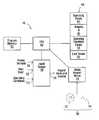
- the genset 10includes an engine 14 and a generator 16 , the engine being coupled to the generator by a shaft 20 .
- the genset 10has a plurality of operating points, each including an engine speed value and a generator electrical power output value.
- the genset 10also has a plurality of cost values associated with operating the genset at respective operating points.
- the apparatus 12further includes a processor circuit 18 , which is operable to select a set of operating points from the plurality of operating points such that a sum of cost values associated with operating points in the set is minimized and such that the engine speed and generator electrical power output values of the operating points in the set increase or decrease monotonically.
- the generator 16further includes an output 22 for delivering the electrical power output to be used, for example, in operation of a hybrid electric vehicle.
- the processor circuit 18also includes an output 28 for producing control signals and the engine 14 includes an interface 30 for receiving an engine control signal from the processor circuit.
- the generator 16may include an interface 32 , for receiving a generator control signal from the processor circuit 18 (for example, to set a field current level in a DC electric generator).
- the processor circuit 18also includes an input 24 for receiving data values such as cost values, and an input 26 for receiving a demand to supply electrical power.
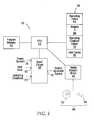
- the processor circuit 18is shown in greater detail in FIG. 2 .
- the processor circuit 18includes a central processing unit (CPU) 40 , a program memory 42 , a random access memory (RAM) 44 , a media reader/writer 46 , and an input output port (I/O) 48 .
- the program memory 42 , the RAM 44 , the media reader/writer 46 , and the I/O 48are all in communication with the CPU 40 .
- the I/O 48includes the input 26 for receiving the power demand. In the embodiment shown the I/O 48 also includes the output 28 for producing an engine/generator control signal to control the engine 14 .
- the I/O 48may optionally include an input 62 for receiving user input, as described later herein.
- the media reader/writer 46facilitates loading program codes into the RAM memory 44 from a computer readable medium, such as a CD ROM disk 52 , or a computer readable signal 54 such as may be received from a network such as a telephone network or the internet, for example.
- the plurality of cost valuesmay be encoded on the computer readable medium 50 , and the CPU 40 may be configured to load the cost values into the processor circuit 18 , and store the cost values in a location 56 in the RAM 44 .
- the RAM 44further includes locations 58 , 60 , and 64 for storing operating condition values, weights a i , and operating points (power output values and corresponding speed values) respectively, as described later herein.
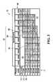
- the table 70includes a plurality of power output value rows 71 , each row corresponding to a generator power output value that the generator is capable of supplying.
- the genset 10is capable of supplying power in 5 kW increments, up to a maximum power of 35 kW. In other embodiments the power increment may be greater than or less than 5 kW, and the maximum power may be higher than 35 kW.
- the plurality of rows 71includes a row 72 corresponding to a no-load power output value, a row 74 corresponding to a 5 kW power output value, a row 76 corresponding to a 10 kW power output value, etc.
- Each row 71includes a plurality of rotational speeds 80 at which the genset 10 is capable of supplying power. For example, the row 76 , corresponding to a 10 kW power output value, may be supplied at any of the rotational speeds 80 .
- Values 82in the table 70 , represent cost values associated with operating the genset 10 at various operating points, each operating point being defined by a power output value and a corresponding rotational speed 80 .
- the value 84represents the operating cost associated with operating the genset 10 at a speed of 2800 rpm while supplying a 10 kW power output.
- the region 90 in the table 70includes high rotational speeds 80 at which it may not be practical to supply low, or no load, power output values.
- the region 92 in the table 70includes low rotational speeds 80 at which it may not be practical to supply high power output values. Accordingly, in this embodiment, no cost values are assigned to operating points in the regions 90 and 92 .
- the plurality of values 82 in the table 70therefore represent operating costs associated with operating at a plurality different operating points at which the genset 10 is capable of supplying electrical power.
- data representing the table 70is encoded on a CD-ROM disk and loaded into the location 56 in the RAM 44 , shown in FIG. 2 .
- the data representing the table 70may be encoded on a computer readable signal and loaded into the location 56 .
- the computer readable signalmay be received over an internet connection, over a serial or parallel cable, a wireless connection, or any other medium for transferring data, for example.
- the apparatus 110includes the genset 10 , shown in FIG. 1 , and also includes the processor circuit 18 , shown in FIG. 1 and FIG. 2 . However, it should be understood that the apparatus 110 may be implemented using a separate processor circuit.
- the output 28 of the processor circuit 18is in communication with the interface 30 of the engine 14 for controlling the engine, and optionally the output 28 may also be in communication with the interface 32 of the generator 16 , for controlling the generator.
- the processor circuit 18also includes an input 112 for receiving operating condition values.
- the engine 14further includes a plurality of sensors 114 for sensing operating conditions of the engine.
- the sensors 114may include, for example, a fuel sensor 116 , a hydrocarbon (HC) sensor 118 , a carbon monoxide (CO) 120 , and a nitrogen-oxide (NO x ) sensor 122 .
- Other sensorsmay be included in the plurality of sensors 114 , such as a particulate matter sensor (not shown).
- the sensors 114 - 122each have an associated output 124 - 130 respectively. Each of the outputs 124 - 130 produce a signal representing the respective operating conditions.
- the outputs 124 - 130are in communication with the input 112 of the processor circuit 18 .
- FIG. 5a flow chart depicting blocks of code for directing the processor circuit 18 in FIG. 2 to produce the plurality of cost values, is shown generally at 160 .
- the blocksgenerally represent codes that may be read from the computer readable medium 50 , and stored in the program memory 42 , for directing the CPU 40 to perform various functions related to producing the plurality of cost values.
- the actual code to implement each blockmay be written in any suitable program language, such as C, C ++ and/or assembly code, for example.
- the processbegins with a first block of codes 162 , which directs the CPU 40 to assign weights a i to the operating conditions and to store the operating condition weights in the location 60 in the RAM 44 .
- the processor circuitmay implement a user interface (not shown) and block 164 may optionally direct the CPU 40 to receive user input at the I/O input 62 (shown in FIG. 2 ).
- the user inputmay be received from a keyboard or other user input device, for example.
- Block 166directs the processor circuit 18 to receive the operating condition values from the sensors 114 (shown in FIG. 4 ) at the input 112 . Block 166 further directs the processor circuit 18 to cause the operating condition values to be stored in the location 58 in the RAM 44 .
- the operating condition valuesare presented in tabular format at 200 .
- the table 200includes operating condition values 224 for a plurality of operating conditions 210 , including a fuel consumption operating condition 202 , a hydrocarbon emission operating condition 204 , a carbon monoxide emission operating condition 206 , and a nitrogen oxide emission operating condition 208 .
- the operating condition values received from the plurality of sensors 114may include operating condition values expressed in a number of different units of measurement.
- the hydrocarbon, carbon monoxide, and nitrogen oxide operating condition valueswhich represent engine emissions, may be expressed in parts per million (ppm), while the fuel consumption operating condition value may be expressed in kilograms of fuel consumed per hour of operation (kg/h).
- block 168directs the processor circuit 18 to normalize the operating condition values stored in the location 58 of the RAM 44 .
- the operating condition values 224 in the table 200 corresponding to each of the operating conditions 210are separately normalized such that each operating condition includes values ranging from 0.000 to 1.000.
- the fuel consumption operating condition valuesmay generally range from 0 kg/h to about 8.4 kg/h for one particular engine 14 , and the values in the table 200 are normalized so that the no load, 1600 rpm fuel consumption value is 0.000 while the 35 kW, 3400 rpm consumption value is 1.000.
- Operating condition values for other operating conditionsare similarly normalized over the operating power range of values 222 and the engine speed range of values 220 . Note that the operating condition values in the Table 200 were determined by experiment and may include noise and/or experimental error and are used herein for illustrative purposes only.
- Block 170directs the processor circuit 18 to read the RAM 44 to retrieve the normalized operating condition values from the location 58 and to read the weights a i stored in the location 60 .
- Block 170further directs the processor circuit 18 to apply the weights to the operating condition values 224 to produce the cost values 82 in the table 70 (shown in FIG. 3 ).
- the cost values 82 in the table 70were generated by applying the function below to the normalized operating condition values in the table 200 :
- C iare the operating condition values 224 corresponding to the plurality of operating conditions 210 .
- the weights a iwere set to unity, which assigns equal weight to each of the operating conditions 210 .
- cost value combination functionsmay also be used to combine the cost values C i in other ways.
- the operating condition values 224 in the table 200may be produced by operating the genset 10 (shown in FIG. 4 ) at the power output values 222 while receiving signals from the sensors 114 , which represent the real-time values of the operating conditions 210 .
- the operating condition valuesmay be produced before operating the genset 10 .
- a manufacturer of the engine 14may provide expected operating condition values for a specific type of engine.
- the operating condition valuesmay be established by performing tests on an engine of type and/or performance similar to the engine 14 .
- Such valuesmay be provided on the computer readable medium 50 and may be loaded into the processor circuit 18 using a media reader, such as the media reader/writer shown at 46 in FIG. 2 .
- the processor circuitmay periodically repeat execution of the blocks 166 , 168 , and 170 , thereby producing a new set of cost values based on changed operating condition values.
- a minimum cost value for each power output row 71may easily be identified by inspection of the values 82 , or by performing a simple linear search for a minimum value in the row.
- the genset 10may include a larger plurality of possible operating points, in which case a simple linear search for a minimum value for each power output row 71 may be slow or impractical, particularly in real-time implementations.
- a golden section searchis used to find the minimum cost value at each successive power output value.
- the golden section searchis a bracketing technique, which may be applied to a set of values to find a single minimum value in the set between an upper bound bracket value and a lower bound bracket value.
- the searchbegins by selecting upper and lower bound brackets at end points of the range of engine speeds 80 in the table 70 .
- the upper and lower bound bracketsare then successively narrowed until a minimum is found.
- the techniquederives its name from the golden ratio, which has been found to be an effective bracketing ratio.
- Applying the golden ratioinvolves selecting an intermediate engine speed 80 between the upper bound bracket and the lower bound bracket that is 0.38197 from one end and 0.61803 from the other end, and then moving the bracket having a greater corresponding cost value 82 , to the intermediate engine speed, which then becomes the new upper or lower bound bracket. The process is then repeated until the minimum cost value coincides with either the upper bound bracket or the lower bound bracket, in which case the lesser of the cost values corresponding to the upper and lower bound brackets is the minimum cost value.
- the application of the golden section search technique to finding the minimum cost value for each power output row 71is described with reference to the row 76 of the table 70 .
- the first step in the application of the techniqueis to select 1600 rpm as the lower bound bracket and 3400 rpm as the upper bound bracket, and to calculate an intermediate point between the upper bound bracket and the lower bound bracket using the golden section ratio of 0.38197, yielding an intermediate point of 2287 rpm.
- the speed value 2200 rpmthe closest value to the calculated intermediate value of 2287 rpm. Since the cost value at 3400 rpm is 0.791, which is larger than the cost values at 2200 rpm and 1600 rpm, a new upper bound bracket of 2200 rpm is selected.
- the golden ratiois again applied to find an intermediate point, which in this case evaluates to 1829 rpm.
- This intermediate pointis closest to the 1800 rpm speed value.
- the upper bound bracket value of 2200 rpmhas a corresponding cost value of 0.550 which is larger than the cost values at 1800 and 1600 rpm.
- the new upper bound bracketis chosen at 1800 rpm. Because there are no intermediate values between the 1800 rpm upper bound bracket value and the 1600 rpm lower bound bracket value, the minimum of these two values represents the minimum cost value in the row 76 , which in this case is 0.526 or 1800 rpm.
- the golden section searchallows quick convergence on a minimum value in a plurality of values having a single minimum between an upper bound and a lower bound.
- the minimum cost value for each power output row 71is indicated in bold italic typeface in the table 70 .
- a set of operating points corresponding to each of the bolded costs values in the table 70would minimize the overall genset operating cost. However such a set of values would result in a rotational speed of the engine increasing in a somewhat sporadic manner in response to monotonically increasing power output values 71 . For example, if the output power were to increase from a no load value to 15 kW, the operating speed at no load would start at 1600 rpm, and then jump to 200 rpm as the power output is increased to 10 kW, and then the speed would reduce to 1800 rpm again at 15 kW.
- While such a set of operating pointsmay optimize the sum of the cost values shown in the table 70 , other operating conditions such as the lifetime of the engine, mechanical stresses in the engine, drivability for hybrid vehicle implementations, and other factors, may not be optimized by selecting these local minimum cost values at each power output value.
- the additional constraintrequires that the engine speed increase (or decrease) monotonically with monotonically increasing (or decreasing) electrical power output value. Accordingly, in response to each increase in power output value, the engine speed value should either stay the same or should increase.
- selecting an optimal set of operating pointsinvolves selecting a set of operating points from the table 70 . This involves selecting a particular rotational speed at each power output value, and then computing a sum of the cost values for the set of operating points. A set of operating points that has the lowest sum of cost values, while meeting the constraint of monotonically increasing speed, will be the optimal set of operating points.
- some power outputsmay be more frequently used than other power outputs.
- power output values proximate a midpoint of the range of power outputs that the generator is capable of supplyingmay be more frequently used than power output values at a lower end and a higher end of the range. Accordingly, in one embodiment, the sums may be computed using the function below:
- b jare weights that cause cost values corresponding to more frequently demanded power output values to be assigned greater weight in the sum than cost values corresponding to less frequently demanded electrical power output values.
- the weights b jmay be used to reflect real world drive cycles when the vehicle is operated in a particular terrain.
- the weight factors b jmay further be modified when genset operating conditions change, thus facilitating adaptation of the genset to a changing environment.
- a dynamic programming techniqueis used to select the set of operating points for the genset 10 .
- dynamic programmingan optimization problem is divided into sub-optimization problems, which are successively optimized to obtain an overall optimized solution.
- the weights b jare all unity (i.e. all power output values have the same importance as per Equation 2).
- higher weightsmay be set for some operating conditions that other operating conditions in accordance with the relative impact of the various conditions on the environment, and/or the cost of operating the genset, for example.
- FIG. 7a flow chart depicting blocks of code for directing the processor circuit 18 (shown in FIG. 2 ) to select the set of operating conditions, is shown generally at 230 .
- the blocksgenerally represent codes that may be read from the computer readable medium 50 , and stored in the program memory 42 , for directing the CPU 40 to perform various functions related to producing the plurality of cost values.
- the actual code to implement each blockmay be written in any suitable program language, such as C, C++ and/or assembly code, for example.
- the processbegins with a first block of codes 232 , which directs the processor circuit 18 to retrieve the first power output value from the location 64 of the RAM 44 .
- FIG. 8shows a graphical depiction of the operating points 82 shown in FIG. 3 , where each circle 250 represents an operating point having a particular power output value 252 (x-axis), and a particular rotational speed 254 (y-axis).
- the first power output value 252is 0 kW.
- the optimizationmay start at a maximum power output value, for example.
- Block 236thus directs the processor circuit 18 to select the engine speed 1600 rpm as the first operating point, since this point has a minimum cost value.
- Block 238directs the processor circuit 18 to determine whether the present power output value is the last power output value. If “NO”, then the process continues at block 240 , where the next power output value is read from the RAM 44 at location 64 . The process then returns to block 234 .
- Block 234again directs the processor circuit to calculate the sum of cost values.
- Block 236thus directs the processor circuit to add the operating point 262 to the set of operating points. The process continues as described above through 10 kW to 35 kW power output values.
- the speeds 200 rpm-3400 rpmwould all satisfy the constraint of monotonically increasing the speed. However, even though the minimum cost for the power output value row 76 occurs at 1800 rpm, the speed 1800 rpm (and 1600 rpm) would not satisfy the constraint. At this point in the process, an operating point 264 corresponding to a speed of 2000 rpm, which meets the constraint but is not a minimum cost operating point, may be selected.
- one or more of the previously selected operating points in the setmay be changed, such that the minimum cost value in row 76 may be selected while meeting the constraint.
- the decision of which alternative to selectmade by calculating a plurality of cost value sums corresponding to possible sets of operating points leading to the minimum cost value (0.309 @ 1800 rpm) and other cost values such as 0.317 @ 1600 rpm and 0.333 @2000 rpm, for example. From the plurality of cost value sums, a set of operating points that yields a minimum sum is selected. For the values of cost values indicated in the table 70 , the minimum sum occurs for the operating point set (0 kw,1600 rpm), (5 kW,2000 rpm), (10 kW,2000 rpm).
- the minimum sum of cost valueswere to correspond to a different set of operating points, this may have resulted in changing a previously selected operating point in the set. For example, if the minimum sum had corresponded to the set of operating points (0 kw;1600 rpm), (5 kW,1800 rpm), (10 kW,1800 rpm), then the operating point at 5 kW would have been changed from 2000 rpm to 1800 rpm.
- Memoizationis a technique used to speed up computer programs by storing the results of previous calculations for re-use, rather than re-computing them each time.
- memoizinghas a significant effect in reducing the number of operations required in selecting a set of operating points, thus facilitating computationally efficient selection of operating points for the genset 10 , when faced by a changing operating condition or change in either of the weights a i or b j .
- the processis successively applied at each of the power output values 252 up to a 35 kW power output value until a complete set of operating points has been selected as indicated by the bold line 258 .
- weights b jwere all set to unity in accordance with Equation 2.
- the weights b jare simply taken into account when applying the dynamic programming technique by calculating the sums in accordance with Equation 3 using weights b i having differing values to account for real-world conditions of use of the genset.
- a hybrid electric vehicle embodiment of the inventionis shown generally at 300 .
- the hybrid vehicle 300includes a first pair of driven wheels 302 and a second pair of wheels 304 .
- the hybrid vehicle 300further includes an electric drive motor 306 , a gearbox 308 and a coupling shaft 310 .
- the drive motor 306is coupled to the driven wheels 302 through the gearbox 308 and the coupling shaft 310 , to provide mechanical power to the driven wheels.
- the hybrid vehicle 300also includes a storage element 312 , which in this embodiment includes a plurality of storage batteries 314 and a plurality of capacitor storage elements.
- the storage element 312is in communication with a first energy bus 318 .
- the batteries 314are nickel metal hydride cells (NiMH), and the capacitor 316 includes one or more ultracapacitors.
- the storage element 312may include batteries only, ultracapicitors only, or may include a flywheel energy storage element. Flywheel energy storage elements generally operate by accelerating an electrically coupled flywheel rotor in a motor/generator to a high speed thus storing inertial energy in the flywheel for later use.
- the hybrid vehicle 300further includes a genset 320 , which as described above includes an engine 322 coupled to an electrical generator 324 .
- the generatoris in communication with a second energy bus 326 .
- the genset 320also includes a processor circuit 332 , which may be the processor circuit 18 shown in FIGS. 1 , 2 , and 4 .
- the engine 320may be any type of internal or external combustion engine, e.g. Otto, Atkinson and diesel cycle engines, Stirling engines, gas turbine engines etc.
- the engine 320may also run on any type of fuel such as gasoline, diesel, biogas or other bio-fuels including cellulosic and other ethanols, propane etc.
- the hybrid vehicle 300also includes a controller 328 , which is in communication with the first and second energy busses 318 and 326 , for receiving electrical energy, and is also in communication with the drive motor 306 for supplying energy to the drive motor to drive the wheels 302 .
- the controllermay include various voltage converters such as a DC-DC converter for example to convert the electrical energy received on the busses 318 and 326 into a voltage suitable for supplying the drive motor 306 .
- the controller 328further includes an output 342 for producing power demand signals. The output 342 is in communication with the processor circuit 332 .
- the hybrid vehicle 300includes a storage element controller 340 , which is in communication with the storage element 312 for monitoring a state of charge of the storage element 312 .
- the storage element controller 340is also in communication with the controller 328 for providing a state of charge signal associated with a state of charge of the storage element 312 to the controller.
- the hybrid vehiclealso includes a foot pedal 329 for producing a signal representing a requested power to the drive motor for driving the wheels.
- the foot pedal 329is in communication with the controller 328 and is disposed in a driving compartment (not shown) of the hybrid vehicle 300 .
- the hybrid vehiclealso includes an accessory 330 , such as compartment lighting, a wiper motor, a compartment cooling fan, etc.
- the controller 328is in communication with the accessory 330 for supplying electrical energy to the accessory at a suitable voltage & current (e.g. at 12V DC).
- the controller 328receives the requested power signal from the foot pedal 329 , and the state of charge signal from the storage element controller 340 , and responds by producing a power demand signal at the output 342 for demanding a power output from the genset 320 .
- the power output demanded from the genset 320 by the controller 328depends on the state of charge of the storage element 312 and the power request signal received from the foot pedal 329 .
- the power demand signal produced by the controller 328may also include an additional demand for supplying power to the accessory 330 .
- the power requested by the operator's depression of the foot pedal 329may thus be supplied by the storage element 312 over the bus 318 , by the genset 320 over the bus 326 , or by a combination of both.
- the request for drive power to be delivered to the wheels 203is thus satisfied by power supplied by the genset 320 alone, or by the storage element 312 alone, or by a combination of a first portion of power supplied by the storage element and a second portion of power supplied by the genset.
- the storage element controllerproduces a state of charge signal indicating that charging of the storage element 312 is required.
- the controller 328then responds by producing a power demand signal to the genset 320 that includes an additional demand for power to charge the storage element 312 , and the genset 320 is required to generate power for satisfying both the power request from the foot pedal 329 , and a power demand for charging the storage element 312 .
- the processor circuit 332 and genset 320operates as described above in connection with the genset 10 and the processor circuit 18 .
- the processor circuit 332receives a set of operating points (for example the operating points shown in FIG. 8 at 258 ) that have been determined externally to the vehicle 300 and stored on a computer readable medium, such as the computer readable medium 50 shown in FIG. 2 .
- the set of operating pointsis then read into the processor circuit 332 using a media reader, such as the media reader/writer 46 shown in FIG. 2 .
- the genset 320When operating the hybrid vehicle 300 , the genset 320 receives the power demand signal from the controller 328 , and responds by running the engine 322 at an engine speed corresponding to the operating point in the set of operating points that corresponds to the demanded power. The generator 324 responds by supplying the demanded level of power to the energy bus 326 .
- the cost values 82may be determined externally to the hybrid vehicle 300 , stored on a computer readable medium, and read into the processor circuit 332 using a media reader.
- the processor circuit 332may further be configured to generate a record of received demands for power outputs during operation of the genset 320 over a period of time.
- the processor circuit 332then calculates the weights b j , assigning greater weight to more frequently used power output values, according to the record of received demands.
- the processor circuit 332is configured to select the set of operating points using the externally supplied cost values, as described above.
- the vehicle 300is able to adapt to a change in environment (for example, when moving the vehicle from a substantially flat terrain, to mountainous terrain) by changing the weights b j .
- the operating condition valuesmay be read into the vehicle by a media reader into the processor circuit 332 , and the cost values may be calculated on-board the hybrid vehicle 300 , thereby facilitating on-board changes to the weights a i in accordance with Equation 1 for altering a desired-trade off between the various operating conditions.
- the vehicle 300is able to select new operating points reflecting a different desired trade off between the operating conditions. For example, when operating the vehicle in a city environment, emissions may have to meet stricter criteria than in more rural environments, and the weights a i may be changed to reflect this difference.
- the operating condition valuesare provided by on-board sensors, such as the sensors 114 shown in FIG. 4 .
- the operating condition values, cost value values and the selection of a set of operating points for the genset 320all take place in on-board the vehicle 300 in the processor circuit 332 .
- the use of a dynamic programming techniqueprovides a computationally efficient method for selecting the operating points, thus reducing a hardware speed requirement for the processor circuit 332 .
- the sensing of operating condition valuesthus facilitates a quick response to changing conditions such as changes in fuel consumption patterns or emissions, due to changes in engine operation over time, for example.
- the hybrid vehicle 300 shown in FIG. 9represents an example of what is often referred to as a “serial hybrid vehicle”, in that the engine 322 is not mechanically coupled to the wheels 302 .
- Other configurations of hybrid vehiclesmay include engines that are coupled to both a generator and to a drive wheel of the vehicle, and may be referred to as “parallel hybrid vehicles”.
- Parallel hybrid vehiclesAt least some of the above described embodiments of the invention may be applicable to various configurations of parallel hybrid vehicles, where an engine is coupled to a generator. For example, when a hybrid vehicle is at a standstill and no power is being provided to the wheels, the engine and generator may be operated using operating points selected as described above.
- an optimization methodis a search method that is able effectively to find a condition, which minimizes the function in Equation 1 or Equation 2, subject to the constraint of monotonically increasing speed.
- One possible alternativeis to compute every possible sum in the range of power output values and engine speeds.
- Such a “brute force” techniqueis easy to implement but has the potential downside of being slow in execution.
- more efficient techniquessuch as steepest descent method, conjugate gradients method, variable metric method, Newton's method, linear programming (including golden search), may be used in place of dynamic programming.
- the method of steepest descentapproaches the minimum in a zig-zag manner, where the new search direction is orthogonal to the previous search direction. However this method converges slowly, since after each step the method searches in an opposite direction.
- the method of conjugate gradientsattempts to alleviate this problems with steepest descent methods to by “learning” from experience. Newton's method results in faster convergence, but not necessarily less computing time compared against steepest descent and conjugate gradient methods.
Landscapes
- Engineering & Computer Science (AREA)
- Mechanical Engineering (AREA)
- Transportation (AREA)
- Power Engineering (AREA)
- Chemical & Material Sciences (AREA)
- Combustion & Propulsion (AREA)
- Life Sciences & Earth Sciences (AREA)
- Automation & Control Theory (AREA)
- Sustainable Development (AREA)
- Sustainable Energy (AREA)
- Physics & Mathematics (AREA)
- General Physics & Mathematics (AREA)
- General Engineering & Computer Science (AREA)
- Theoretical Computer Science (AREA)
- Chemical Kinetics & Catalysis (AREA)
- Pathology (AREA)
- Analytical Chemistry (AREA)
- Biochemistry (AREA)
- General Health & Medical Sciences (AREA)
- Immunology (AREA)
- Fluid Mechanics (AREA)
- Computer Hardware Design (AREA)
- Health & Medical Sciences (AREA)
- Control Of Vehicle Engines Or Engines For Specific Uses (AREA)
- Electric Propulsion And Braking For Vehicles (AREA)
- Control Of Eletrric Generators (AREA)
- Supply And Distribution Of Alternating Current (AREA)
Abstract
Description
where Ojare the cost values associated with the plurality of operating points, Ciare the operating condition values224 corresponding to the plurality of operating
where Oiare the cost values82 at each of n power output values71 (in
where bjare weights that cause cost values corresponding to more frequently demanded power output values to be assigned greater weight in the sum than cost values corresponding to less frequently demanded electrical power output values. In a hybrid electric vehicle, the weights bjmay be used to reflect real world drive cycles when the vehicle is operated in a particular terrain. The weight factors bjmay further be modified when genset operating conditions change, thus facilitating adaptation of the genset to a changing environment.
Dynamic Programming Selection Technique
Claims (58)
Priority Applications (5)
| Application Number | Priority Date | Filing Date | Title |
|---|---|---|---|
| US11/821,855US8346416B2 (en) | 2006-06-26 | 2007-06-26 | Method, apparatus, signals and media, for selecting operating conditions of a genset |
| US13/674,552US20130090864A1 (en) | 2006-06-26 | 2012-11-12 | Method, apparatus, signals and media, for selecting operating conditions of a genset |
| US13/674,624US8655570B2 (en) | 2006-06-26 | 2012-11-12 | Method, apparatus, signals and media, for selecting operating conditions of a genset |
| US14/148,436US9020734B2 (en) | 2006-06-26 | 2014-01-06 | Method, apparatus, signals and media, for selecting operating conditions of a genset |
| US14/675,208US9403529B2 (en) | 2006-06-26 | 2015-03-31 | Method, apparatus, signals and media, for selecting operating conditions of a genset |
Applications Claiming Priority (2)
| Application Number | Priority Date | Filing Date | Title |
|---|---|---|---|
| US81650306P | 2006-06-26 | 2006-06-26 | |
| US11/821,855US8346416B2 (en) | 2006-06-26 | 2007-06-26 | Method, apparatus, signals and media, for selecting operating conditions of a genset |
Related Child Applications (2)
| Application Number | Title | Priority Date | Filing Date |
|---|---|---|---|
| US13/674,624ContinuationUS8655570B2 (en) | 2006-06-26 | 2012-11-12 | Method, apparatus, signals and media, for selecting operating conditions of a genset |
| US13/674,552DivisionUS20130090864A1 (en) | 2006-06-26 | 2012-11-12 | Method, apparatus, signals and media, for selecting operating conditions of a genset |
Publications (2)
| Publication Number | Publication Date |
|---|---|
| US20080122228A1 US20080122228A1 (en) | 2008-05-29 |
| US8346416B2true US8346416B2 (en) | 2013-01-01 |
Family
ID=38845070
Family Applications (5)
| Application Number | Title | Priority Date | Filing Date |
|---|---|---|---|
| US11/821,855Active2030-11-16US8346416B2 (en) | 2006-06-26 | 2007-06-26 | Method, apparatus, signals and media, for selecting operating conditions of a genset |
| US13/674,624ActiveUS8655570B2 (en) | 2006-06-26 | 2012-11-12 | Method, apparatus, signals and media, for selecting operating conditions of a genset |
| US13/674,552AbandonedUS20130090864A1 (en) | 2006-06-26 | 2012-11-12 | Method, apparatus, signals and media, for selecting operating conditions of a genset |
| US14/148,436ActiveUS9020734B2 (en) | 2006-06-26 | 2014-01-06 | Method, apparatus, signals and media, for selecting operating conditions of a genset |
| US14/675,208ActiveUS9403529B2 (en) | 2006-06-26 | 2015-03-31 | Method, apparatus, signals and media, for selecting operating conditions of a genset |
Family Applications After (4)
| Application Number | Title | Priority Date | Filing Date |
|---|---|---|---|
| US13/674,624ActiveUS8655570B2 (en) | 2006-06-26 | 2012-11-12 | Method, apparatus, signals and media, for selecting operating conditions of a genset |
| US13/674,552AbandonedUS20130090864A1 (en) | 2006-06-26 | 2012-11-12 | Method, apparatus, signals and media, for selecting operating conditions of a genset |
| US14/148,436ActiveUS9020734B2 (en) | 2006-06-26 | 2014-01-06 | Method, apparatus, signals and media, for selecting operating conditions of a genset |
| US14/675,208ActiveUS9403529B2 (en) | 2006-06-26 | 2015-03-31 | Method, apparatus, signals and media, for selecting operating conditions of a genset |
Country Status (5)
| Country | Link |
|---|---|
| US (5) | US8346416B2 (en) |
| EP (3) | EP2620342B1 (en) |
| CA (1) | CA2659087C (en) |
| ES (1) | ES2433373T3 (en) |
| WO (1) | WO2008000071A1 (en) |
Cited By (9)
| Publication number | Priority date | Publication date | Assignee | Title |
|---|---|---|---|---|
| US20100198439A1 (en)* | 2009-01-30 | 2010-08-05 | Empire Technology Development Llc | Hybrid vehicle driving system, hybrid vehicle, and driving method |
| US20130332015A1 (en)* | 2010-09-04 | 2013-12-12 | Clement Dextreit | Controller and method of control of a hybrid electric vehicle |
| US9020734B2 (en) | 2006-06-26 | 2015-04-28 | Ge Hybrid Technologies, Llc | Method, apparatus, signals and media, for selecting operating conditions of a genset |
| US9849804B2 (en)* | 2015-10-02 | 2017-12-26 | Hyundai Motor Company | Method and system for controlling battery SOC of hybrid vehicle |
| US10205322B1 (en) | 2015-03-09 | 2019-02-12 | Cummins Power Generation Ip, Inc. | Economically efficient operation of a power generator |
| US10578040B2 (en) | 2017-09-15 | 2020-03-03 | Toyota Motor Engineering & Manufacturing North America, Inc. | Smoothed and regularized Fischer-Burmeister solver for embedded real-time constrained optimal control problems in automotive systems |
| US10739768B2 (en) | 2018-08-08 | 2020-08-11 | Toyota Motor Engineering & Manufacturing North America, Inc. | Smoothed and regularized Fischer-Burmeister solver for embedded real-time constrained optimal control problems in autonomous systems |
| US10998732B2 (en) | 2019-03-20 | 2021-05-04 | Caterpillar Inc. | System and method for diverse multi-source energy management |
| US11188045B2 (en) | 2019-03-18 | 2021-11-30 | Caterpillar Inc. | Energy management system with gensets and energy storage |
Families Citing this family (34)
| Publication number | Priority date | Publication date | Assignee | Title |
|---|---|---|---|---|
| JP4479488B2 (en)* | 2004-12-01 | 2010-06-09 | 株式会社デンソー | Exhaust power generator |
| JP4449882B2 (en)* | 2005-10-14 | 2010-04-14 | 株式会社デンソー | Vehicle power generation control device |
| CA2650224C (en) | 2006-05-09 | 2014-02-25 | Azure Dynamics Inc. | Process and apparatus for reducing nitrogen oxide emissions in genset systems |
| JP4780402B2 (en)* | 2006-06-27 | 2011-09-28 | 株式会社デンソー | Vehicle power supply |
| US7826939B2 (en) | 2006-09-01 | 2010-11-02 | Azure Dynamics, Inc. | Method, apparatus, signals, and medium for managing power in a hybrid vehicle |
| US8010247B2 (en)* | 2007-11-03 | 2011-08-30 | GM Global Technology Operations LLC | Method for operating an engine in a hybrid powertrain system |
| US8897975B2 (en)* | 2007-11-04 | 2014-11-25 | GM Global Technology Operations LLC | Method for controlling a powertrain system based on penalty costs |
| DE102010007632A1 (en)* | 2010-02-05 | 2011-08-11 | Dr. Ing. h.c. F. Porsche Aktiengesellschaft, 70435 | hybrid vehicle |
| US8590330B2 (en) | 2010-06-03 | 2013-11-26 | Thermo King Corporation | Electric transport refrigeration unit with temperature-based diesel operation |
| GB201107280D0 (en)* | 2011-04-28 | 2011-06-15 | Imp Innovations Ltd | A drive train for a hybrid electric vehicle and a method of operating such a vehicle |
| AT512023B1 (en) | 2011-10-13 | 2015-06-15 | Avl List Gmbh | METHOD FOR OPERATING A POWER GENERATING AGGREGATE |
| DE102012201270A1 (en)* | 2012-01-30 | 2013-08-01 | Bayerische Motoren Werke Aktiengesellschaft | Method for determining operating point of range extender in electric car, involves selecting speed stage for operation of extender from discrete target rotation speed stages of electric machine in dependence of nominal output of extender |
| GB201208519D0 (en)* | 2012-05-15 | 2012-06-27 | Passivsystems Ltd | Predictive temperature management system controller |
| EP2875566A1 (en)* | 2012-07-17 | 2015-05-27 | Caterpillar (Ni) Limited | Voltage regulator system for a genset |
| CN103847729B (en)* | 2012-12-05 | 2016-05-18 | 上海汽车集团股份有限公司 | In new-energy automobile hybrid power system, control the method and apparatus of interfering moment of torsion |
| US9099882B2 (en)* | 2013-01-18 | 2015-08-04 | Caterpillar Inc. | Turbine engine hybrid power supply |
| GB2514120B (en)* | 2013-05-13 | 2020-05-27 | Grass Valley Ltd | Video processing |
| US10609328B2 (en) | 2013-05-13 | 2020-03-31 | Grass Valley Limited | Video processing using a one-dimensional control function to control processing time and error |
| JP5876442B2 (en)* | 2013-05-17 | 2016-03-02 | トヨタ自動車株式会社 | Hybrid vehicle |
| US9067587B1 (en)* | 2014-01-17 | 2015-06-30 | Ford Global Technologies, Llc | Torque based energy management in hybrid vehicle |
| US9500151B2 (en)* | 2014-02-06 | 2016-11-22 | Ford Global Technologies, Llc | Non-intrusive exhaust gas sensor monitoring |
| US9817466B2 (en) | 2014-04-17 | 2017-11-14 | Arm Limited | Power saving by reusing results of identical micro-operations |
| US9933841B2 (en)* | 2014-04-17 | 2018-04-03 | Arm Limited | Reuse of results of back-to-back micro-operations |
| US10514928B2 (en)* | 2014-04-17 | 2019-12-24 | Arm Limited | Preventing duplicate execution by sharing a result between different processing lanes assigned micro-operations that generate the same result |
| US9246425B2 (en)* | 2014-04-29 | 2016-01-26 | Gulfstream Aerospace Corporation | Apparatus and systems for engine and generator control within an aircraft |
| JP6475825B2 (en)* | 2014-10-02 | 2019-02-27 | ボルボトラックコーポレーション | Method for controlling the energy flow of a vehicle performed by a control unit |
| WO2016070887A1 (en)* | 2014-11-06 | 2016-05-12 | Volvo Truck Corporation | A hybrid vehicle and a method for energy management of a hybrid vehicle |
| CA2985345A1 (en)* | 2015-05-08 | 2016-11-17 | FlowJo, LLC | Data discovery nodes |
| EP3601773A1 (en) | 2017-03-31 | 2020-02-05 | Generac Power Systems, Inc. | Carbon monoxide detecting system for internal combustion engine-based machines |
| EP3505379B1 (en) | 2017-12-26 | 2021-02-17 | Ikerlan, S. Coop. | Method for obtaining and storing the optimal operating points of a generator set comprising a heat engine coupled to an electric generator |
| KR102648822B1 (en)* | 2019-04-24 | 2024-03-19 | 현대자동차주식회사 | SOC control method and apparatus for improving fuel efficiency of hybrid vehicle |
| EP3944977A1 (en)* | 2020-07-31 | 2022-02-02 | Volvo Car Corporation | Operating point controller |
| US12039355B2 (en)* | 2020-08-24 | 2024-07-16 | Juniper Networks, Inc. | Intent-based telemetry collection service with supported telemetry protocol in a virtualized computing infrastructure |
| CN116505700B (en)* | 2023-06-25 | 2023-09-12 | 江苏国蓉控股有限公司 | Steady flow pipeline structure of water-cooled generator set |
Citations (67)
| Publication number | Priority date | Publication date | Assignee | Title |
|---|---|---|---|---|
| US2916635A (en) | 1956-05-29 | 1959-12-08 | Specialties Dev Corp | Means for controlling the speed of turbines |
| US3225542A (en) | 1964-03-16 | 1965-12-28 | Oilgear Co | Speed control system |
| US3261007A (en) | 1963-04-24 | 1966-07-12 | Continental Elektro Ind Ag | Measuring device for determining angular position |
| US4083052A (en) | 1976-06-16 | 1978-04-04 | Sangamo Electric Company | Electronic tachograph |
| US4407132A (en) | 1980-02-20 | 1983-10-04 | Daihatsu Motor Co., Ltd. | Control apparatus and method for engine/electric hybrid vehicle |
| US4475105A (en) | 1982-09-24 | 1984-10-02 | Tokyo Shibaura Denki Kabushiki Kaisha | System for detecting mechanical movement |
| JPH01144101A (en) | 1987-11-30 | 1989-06-06 | Mitsubishi Heavy Ind Ltd | Fuel cost minimum operation controller for co-generation plant |
| US4905544A (en) | 1975-09-25 | 1990-03-06 | Ganoung David P | Powertrain control apparatus for improving fuel economy |
| GB2267364A (en) | 1992-05-28 | 1993-12-01 | Daimler Benz Ag | Method for controlling a hybrid drive which drives a vehicle |
| US5343970A (en) | 1992-09-21 | 1994-09-06 | Severinsky Alex J | Hybrid electric vehicle |
| US5345761A (en) | 1993-12-02 | 1994-09-13 | Ford Motor Company | Energy management system for hybrid vehicle |
| US5547433A (en) | 1996-05-09 | 1996-08-20 | Yang; Tai-Her | Distributed differential coupling combined power system |
| EP0867323A2 (en) | 1997-03-24 | 1998-09-30 | Toyota Jidosha Kabushiki Kaisha | Energy flow management in hybrid vehicle power output apparatus |
| US5898282A (en) | 1996-08-02 | 1999-04-27 | B.C. Research Inc. | Control system for a hybrid vehicle |
| US5939794A (en) | 1995-07-25 | 1999-08-17 | Nippon Soken, Inc. | Engine control system for hybrid vehicle |
| US6009965A (en) | 1997-08-25 | 2000-01-04 | Honda Giken Kogyo Kabushiki Kaisha | Torque shock alleviating device in hybrid vehicle |
| US6054844A (en)* | 1998-04-21 | 2000-04-25 | The Regents Of The University Of California | Control method and apparatus for internal combustion engine electric hybrid vehicles |
| US6083138A (en) | 1998-03-20 | 2000-07-04 | Nissan Motor Co., Ltd. | Hybrid drive control system for vehicle |
| US6098734A (en) | 1996-06-06 | 2000-08-08 | Isuzu Ceramics Research Institute Co., Ltd. | Hybrid powered automobile with controller |
| US6242873B1 (en) | 2000-01-31 | 2001-06-05 | Azure Dynamics Inc. | Method and apparatus for adaptive hybrid vehicle control |
| US6266956B1 (en) | 1998-12-22 | 2001-07-31 | Toyota Jidosha Kabushiki Kaisha | Exhaust emission control system of hybrid car |
| US6314346B1 (en) | 1998-12-07 | 2001-11-06 | Honda Giken Kogyo Kabushiki Kaisha | Control system for hybrid vehicle |
| US6319168B1 (en) | 2000-04-25 | 2001-11-20 | General Motors Corporation | Apparatus and method for active transmission synchronization and shifting |
| CA2351911A1 (en) | 2000-06-30 | 2001-12-30 | Ford Global Technologies, Inc. | Method and apparatus for determining the operational energy cost of a hybrid vehicle |
| WO2002042110A1 (en) | 2000-11-23 | 2002-05-30 | Ricardo Consulting Engineers Limited | Hybrid power sources distribution management |
| US20020065165A1 (en) | 2000-10-31 | 2002-05-30 | Anders Lasson | Method and arrangement in a hybrid vehicle for maximizing efficiency by operating the engine at sub-optimum conditions |
| US6421599B1 (en) | 2001-08-09 | 2002-07-16 | Ford Global Technologies, Inc. | Control strategy for an internal combustion engine in a hybrid vehicle |
| WO2002058209A1 (en) | 2001-01-03 | 2002-07-25 | The Regents Of The University Of California | Method for controlling the operating characteristics of a hybrid electric vehicle |
| US6480767B2 (en) | 2000-09-22 | 2002-11-12 | Nissan Motor Co., Ltd. | Control system for hybrid vehicle |
| US6519513B2 (en) | 2001-03-01 | 2003-02-11 | Hitachi, Ltd. | Hybrid vehicle control apparatus |
| US6555991B1 (en) | 2002-02-05 | 2003-04-29 | Andrew Michael Zettel | Battery operating condition dependent method and apparatus for controlling energy transfer between an energy bus and a system of batteries |
| US6574535B1 (en) | 2000-05-31 | 2003-06-03 | General Motors Corporation | Apparatus and method for active driveline damping with clunk control |
| US6662096B2 (en) | 2001-03-01 | 2003-12-09 | Nissan Motor Co., Ltd. | Vehicle drive system and vehicle controlling method |
| EP1375237A2 (en) | 1997-09-15 | 2004-01-02 | Honda Giken Kogyo Kabushiki Kaisha | Controlling apparatus for a hybrid car |
| US20040020206A1 (en) | 2001-05-07 | 2004-02-05 | Sullivan Timothy J. | Heat energy utilization system |
| US6715572B2 (en) | 2001-06-01 | 2004-04-06 | Honda Giken Kogyo Kabushiki Kaisha | Control system for hybrid vehicle |
| US6741923B2 (en) | 2002-05-16 | 2004-05-25 | Nissan Motor Co., Ltd. | Vehicle driving force control apparatus |
| US6768621B2 (en) | 2002-01-18 | 2004-07-27 | Solectria Corporation | Contactor feedback and precharge/discharge circuit |
| US20040164616A1 (en) | 2003-02-25 | 2004-08-26 | Denso Corporation | Method for controlling vehicular electric system |
| WO2004071800A1 (en) | 2003-02-06 | 2004-08-26 | Wavecrest Laboratories Llc | Adaptive electric vehicle |
| US20040174125A1 (en) | 2000-12-27 | 2004-09-09 | Transportation Techniques Llc | Method and apparatus for adaptive control of hybrid electric vehicle components |
| US20040245947A1 (en)* | 2000-12-27 | 2004-12-09 | Transportation Techniques, Llc | Method and apparatus for adaptive control and protection of hybrid electric vehicle systems |
| US20040254695A1 (en) | 2003-04-22 | 2004-12-16 | Nissan Motor Co., Ltd. | Drive force control for hybrid electric vehicle |
| US20050024061A1 (en) | 1997-11-03 | 2005-02-03 | Michael Cox | Energy management system for automotive vehicle |
| US20050057098A1 (en) | 2002-02-28 | 2005-03-17 | Bouchon Nicolas Louis | Methods of supplying energy to an energy bus in a hybrid electric vehicle, and apparatuses, media and signals for the same |
| US6879054B2 (en) | 2002-03-15 | 2005-04-12 | Azure Dynamics Inc. | Process, apparatus, media and signals for controlling operating conditions of a hybrid electric vehicle to optimize operating characteristics of the vehicle |
| US20050080537A1 (en) | 2003-10-14 | 2005-04-14 | Cawthorne William R. | Optimal selection of input torque considering battery utilization for a hybrid electric vehicle |
| US20050246076A1 (en) | 2004-04-30 | 2005-11-03 | Jyh-Shin Chen | Torque management algorithm for hybrid electric vehicles |
| US6991052B2 (en) | 1998-03-19 | 2006-01-31 | Hitachi, Ltd. | Hybrid car |
| US7017348B2 (en) | 2003-04-09 | 2006-03-28 | Aisin Aw Co., Ltd. | Control device for a hybrid vehicle |
| US7024290B2 (en) | 2004-07-30 | 2006-04-04 | Ford Global Technologies, Llc | Active motor damping to mitigate electric vehicle driveline oscillations |
| US20060106524A1 (en)* | 2001-01-19 | 2006-05-18 | Transportation Techniques, Llc | Hybrid electric vehicle and method of selectively operating the hybrid electric vehicle |
| US20060108163A1 (en) | 2004-11-25 | 2006-05-25 | Honda Motor Co., Ltd. | Control system for hybrid vehicle |
| US20060122737A1 (en) | 2004-12-08 | 2006-06-08 | Denso Corporation | Power control apparatus and method for electrical system of vehicle |
| US20060237247A1 (en)* | 1998-09-14 | 2006-10-26 | Paice Llc | Hybrid vehicles |
| US20060276288A1 (en)* | 2005-06-07 | 2006-12-07 | Aisin Aw Co., Ltd. | Hybrid drive unit |
| US7178618B2 (en) | 2001-11-29 | 2007-02-20 | Toyota Jidosha Kabushiki Kaisha | Vehicular control apparatus and method |
| US20070074516A1 (en) | 2005-10-03 | 2007-04-05 | General Electric Company | Method of controlling bypass air split to gas turbine combustor |
| US7223203B2 (en) | 2004-09-01 | 2007-05-29 | Ford Global Technologies, Llc | Method of detecting torque disturbances in a hybrid vehicle |
| US20070149348A1 (en) | 2005-12-23 | 2007-06-28 | Holmes Alan G | Vehicle propulsion system |
| US20070262586A1 (en) | 2006-05-09 | 2007-11-15 | Nicolas Bouchon | Process and apparatus for reducing nitrogen oxide emissions in genset systems |
| US7315774B2 (en) | 2006-03-22 | 2008-01-01 | Gm Global Technology Operations, Inc. | Jerk management using multivariable active driveline damping |
| US20080059013A1 (en) | 2006-09-01 | 2008-03-06 | Wei Liu | Method, apparatus, signals, and medium for managing power in a hybrid vehicle |
| US20080236913A1 (en) | 2007-03-28 | 2008-10-02 | Kazuhiro Ichimoto | Power output apparatus and vehicle equipped with the same, and method for controlling power output apparatus |
| US7480555B2 (en) | 2004-12-16 | 2009-01-20 | Eaton Corporation | Method for controlling centrifugal clutch engagement using engine torque requests |
| US7562730B2 (en) | 2005-03-03 | 2009-07-21 | Toyota Jidosha Kabushiki Kaisha | Hybrid vehicle and control method of hybrid vehicle |
| US7577507B2 (en) | 2006-03-22 | 2009-08-18 | Gm Global Technology Operations, Inc. | Driveline lash estimation and clunk management using multivariable active driveline damping |
Family Cites Families (17)
| Publication number | Priority date | Publication date | Assignee | Title |
|---|---|---|---|---|
| PL186824B1 (en)* | 1996-12-20 | 2004-03-31 | Ponte Manuel Dos Santos Da | Hybrid generator |
| JP3536581B2 (en)* | 1997-04-16 | 2004-06-14 | 日産自動車株式会社 | Power generation control device for hybrid electric vehicle |
| JP3624831B2 (en) | 2000-12-28 | 2005-03-02 | 株式会社デンソー | Vehicle power supply device and engine drive regulation support device |
| JP3624841B2 (en)* | 2001-03-06 | 2005-03-02 | 日産自動車株式会社 | Vehicle control device |
| US7137344B2 (en)* | 2001-03-27 | 2006-11-21 | General Electric Company | Hybrid energy off highway vehicle load control system and method |
| US20040015255A1 (en) | 2002-01-16 | 2004-01-22 | Ballard Power Systems Corporation | Process for the optimization of the design of an electric power train |
| US7383902B2 (en)* | 2002-12-20 | 2008-06-10 | Hitachi, Ltd. | Hybrid car and control apparatus therefor, and hybrid four-wheel-drive car and control apparatus therefor |
| US7324902B2 (en)* | 2003-02-18 | 2008-01-29 | General Motors Corporation | Method and apparatus for generalized recursive least-squares process for battery state of charge and state of health |
| US7176658B2 (en)* | 2003-06-02 | 2007-02-13 | Magnetic Applications Inc. | Controller for permanent magnet alternator |
| JP4062264B2 (en)* | 2003-06-06 | 2008-03-19 | アイシン・エィ・ダブリュ株式会社 | Vehicle drive control device, vehicle drive control method, and program |
| JP4254693B2 (en)* | 2004-11-08 | 2009-04-15 | トヨタ自動車株式会社 | Driving device and automobile equipped with the same |
| JP2006248469A (en)* | 2005-03-14 | 2006-09-21 | Hitachi Ltd | Electric four-wheel drive vehicle and its control device |
| JP4241676B2 (en)* | 2005-06-27 | 2009-03-18 | トヨタ自動車株式会社 | POWER OUTPUT DEVICE, VEHICLE MOUNTING THE SAME, AND METHOD FOR CONTROLLING POWER OUTPUT DEVICE |
| JP3927584B2 (en)* | 2005-10-26 | 2007-06-13 | 三菱電機株式会社 | Power control device for automobile |
| US7491144B2 (en)* | 2006-05-11 | 2009-02-17 | Gm Global Technology Operations, Inc. | Single mode, compound-split transmission with dual mechanical paths and fixed reduction ratio |
| US8346416B2 (en) | 2006-06-26 | 2013-01-01 | Azure Dynamics, Inc. | Method, apparatus, signals and media, for selecting operating conditions of a genset |
| US7563730B2 (en) | 2006-08-31 | 2009-07-21 | Micron Technology, Inc. | Hafnium lanthanide oxynitride films |
- 2007
- 2007-06-26USUS11/821,855patent/US8346416B2/enactiveActive
- 2007-06-26CACA2659087Apatent/CA2659087C/enactiveActive
- 2007-06-26EPEP12197542.9Apatent/EP2620342B1/enactiveActive
- 2007-06-26EPEP12197539.5Apatent/EP2620341B1/enactiveActive
- 2007-06-26ESES07720049Tpatent/ES2433373T3/enactiveActive
- 2007-06-26WOPCT/CA2007/001135patent/WO2008000071A1/enactiveApplication Filing
- 2007-06-26EPEP07720049.1Apatent/EP2035270B1/enactiveActive
- 2012
- 2012-11-12USUS13/674,624patent/US8655570B2/enactiveActive
- 2012-11-12USUS13/674,552patent/US20130090864A1/ennot_activeAbandoned
- 2014
- 2014-01-06USUS14/148,436patent/US9020734B2/enactiveActive
- 2015
- 2015-03-31USUS14/675,208patent/US9403529B2/enactiveActive
Patent Citations (74)
| Publication number | Priority date | Publication date | Assignee | Title |
|---|---|---|---|---|
| US2916635A (en) | 1956-05-29 | 1959-12-08 | Specialties Dev Corp | Means for controlling the speed of turbines |
| US3261007A (en) | 1963-04-24 | 1966-07-12 | Continental Elektro Ind Ag | Measuring device for determining angular position |
| US3225542A (en) | 1964-03-16 | 1965-12-28 | Oilgear Co | Speed control system |
| US4905544A (en) | 1975-09-25 | 1990-03-06 | Ganoung David P | Powertrain control apparatus for improving fuel economy |
| US4083052A (en) | 1976-06-16 | 1978-04-04 | Sangamo Electric Company | Electronic tachograph |
| US4407132A (en) | 1980-02-20 | 1983-10-04 | Daihatsu Motor Co., Ltd. | Control apparatus and method for engine/electric hybrid vehicle |
| US4475105A (en) | 1982-09-24 | 1984-10-02 | Tokyo Shibaura Denki Kabushiki Kaisha | System for detecting mechanical movement |
| JPH01144101A (en) | 1987-11-30 | 1989-06-06 | Mitsubishi Heavy Ind Ltd | Fuel cost minimum operation controller for co-generation plant |
| GB2267364A (en) | 1992-05-28 | 1993-12-01 | Daimler Benz Ag | Method for controlling a hybrid drive which drives a vehicle |
| US5327992A (en) | 1992-05-28 | 1994-07-12 | Mercedes-Benz Ag | Method for controlling a hybrid drive which drives a vehicle |
| US5343970A (en) | 1992-09-21 | 1994-09-06 | Severinsky Alex J | Hybrid electric vehicle |
| US5345761A (en) | 1993-12-02 | 1994-09-13 | Ford Motor Company | Energy management system for hybrid vehicle |
| US5939794A (en) | 1995-07-25 | 1999-08-17 | Nippon Soken, Inc. | Engine control system for hybrid vehicle |
| US5547433A (en) | 1996-05-09 | 1996-08-20 | Yang; Tai-Her | Distributed differential coupling combined power system |
| US6098734A (en) | 1996-06-06 | 2000-08-08 | Isuzu Ceramics Research Institute Co., Ltd. | Hybrid powered automobile with controller |
| US5898282A (en) | 1996-08-02 | 1999-04-27 | B.C. Research Inc. | Control system for a hybrid vehicle |
| EP0867323A2 (en) | 1997-03-24 | 1998-09-30 | Toyota Jidosha Kabushiki Kaisha | Energy flow management in hybrid vehicle power output apparatus |
| US6009965A (en) | 1997-08-25 | 2000-01-04 | Honda Giken Kogyo Kabushiki Kaisha | Torque shock alleviating device in hybrid vehicle |
| EP1375237A2 (en) | 1997-09-15 | 2004-01-02 | Honda Giken Kogyo Kabushiki Kaisha | Controlling apparatus for a hybrid car |
| US20050024061A1 (en) | 1997-11-03 | 2005-02-03 | Michael Cox | Energy management system for automotive vehicle |
| US6991052B2 (en) | 1998-03-19 | 2006-01-31 | Hitachi, Ltd. | Hybrid car |
| US6083138A (en) | 1998-03-20 | 2000-07-04 | Nissan Motor Co., Ltd. | Hybrid drive control system for vehicle |
| US6054844A (en)* | 1998-04-21 | 2000-04-25 | The Regents Of The University Of California | Control method and apparatus for internal combustion engine electric hybrid vehicles |
| US6809429B1 (en) | 1998-04-21 | 2004-10-26 | The Regents Of The University Of California | Control method and apparatus for internal combustion engine electric hybrid vehicles |
| US20060237247A1 (en)* | 1998-09-14 | 2006-10-26 | Paice Llc | Hybrid vehicles |
| US6314346B1 (en) | 1998-12-07 | 2001-11-06 | Honda Giken Kogyo Kabushiki Kaisha | Control system for hybrid vehicle |
| US6266956B1 (en) | 1998-12-22 | 2001-07-31 | Toyota Jidosha Kabushiki Kaisha | Exhaust emission control system of hybrid car |
| US6242873B1 (en) | 2000-01-31 | 2001-06-05 | Azure Dynamics Inc. | Method and apparatus for adaptive hybrid vehicle control |
| US6319168B1 (en) | 2000-04-25 | 2001-11-20 | General Motors Corporation | Apparatus and method for active transmission synchronization and shifting |
| US6574535B1 (en) | 2000-05-31 | 2003-06-03 | General Motors Corporation | Apparatus and method for active driveline damping with clunk control |
| US6335610B1 (en) | 2000-06-30 | 2002-01-01 | Ford Global Technologies, Inc. | Method and apparatus for determining the operational energy cost of a hybrid vehicle |
| CA2351911A1 (en) | 2000-06-30 | 2001-12-30 | Ford Global Technologies, Inc. | Method and apparatus for determining the operational energy cost of a hybrid vehicle |
| US6480767B2 (en) | 2000-09-22 | 2002-11-12 | Nissan Motor Co., Ltd. | Control system for hybrid vehicle |
| US6500089B2 (en) | 2000-10-31 | 2002-12-31 | Ford Global Technologies, Inc. | Method and arrangement in a hybrid vehicle for maximizing efficiency by operating the engine at sub-optimum conditions |
| US20020065165A1 (en) | 2000-10-31 | 2002-05-30 | Anders Lasson | Method and arrangement in a hybrid vehicle for maximizing efficiency by operating the engine at sub-optimum conditions |
| WO2002042110A1 (en) | 2000-11-23 | 2002-05-30 | Ricardo Consulting Engineers Limited | Hybrid power sources distribution management |
| US20040074682A1 (en) | 2000-11-23 | 2004-04-22 | Fussey Peter Michael | Hybrid powder sources distribution management |
| US20040245947A1 (en)* | 2000-12-27 | 2004-12-09 | Transportation Techniques, Llc | Method and apparatus for adaptive control and protection of hybrid electric vehicle systems |
| US20040174125A1 (en) | 2000-12-27 | 2004-09-09 | Transportation Techniques Llc | Method and apparatus for adaptive control of hybrid electric vehicle components |
| WO2002058209A1 (en) | 2001-01-03 | 2002-07-25 | The Regents Of The University Of California | Method for controlling the operating characteristics of a hybrid electric vehicle |
| US20060106524A1 (en)* | 2001-01-19 | 2006-05-18 | Transportation Techniques, Llc | Hybrid electric vehicle and method of selectively operating the hybrid electric vehicle |
| US6662096B2 (en) | 2001-03-01 | 2003-12-09 | Nissan Motor Co., Ltd. | Vehicle drive system and vehicle controlling method |
| US6519513B2 (en) | 2001-03-01 | 2003-02-11 | Hitachi, Ltd. | Hybrid vehicle control apparatus |
| US20040020206A1 (en) | 2001-05-07 | 2004-02-05 | Sullivan Timothy J. | Heat energy utilization system |
| US6715572B2 (en) | 2001-06-01 | 2004-04-06 | Honda Giken Kogyo Kabushiki Kaisha | Control system for hybrid vehicle |
| US6421599B1 (en) | 2001-08-09 | 2002-07-16 | Ford Global Technologies, Inc. | Control strategy for an internal combustion engine in a hybrid vehicle |
| US7178618B2 (en) | 2001-11-29 | 2007-02-20 | Toyota Jidosha Kabushiki Kaisha | Vehicular control apparatus and method |
| US6768621B2 (en) | 2002-01-18 | 2004-07-27 | Solectria Corporation | Contactor feedback and precharge/discharge circuit |
| US6555991B1 (en) | 2002-02-05 | 2003-04-29 | Andrew Michael Zettel | Battery operating condition dependent method and apparatus for controlling energy transfer between an energy bus and a system of batteries |
| US20050057098A1 (en) | 2002-02-28 | 2005-03-17 | Bouchon Nicolas Louis | Methods of supplying energy to an energy bus in a hybrid electric vehicle, and apparatuses, media and signals for the same |
| US6909200B2 (en) | 2002-02-28 | 2005-06-21 | Azure Dynamics Inc. | Methods of supplying energy to an energy bus in a hybrid electric vehicle, and apparatuses, media and signals for the same |
| US6879054B2 (en) | 2002-03-15 | 2005-04-12 | Azure Dynamics Inc. | Process, apparatus, media and signals for controlling operating conditions of a hybrid electric vehicle to optimize operating characteristics of the vehicle |
| US6741923B2 (en) | 2002-05-16 | 2004-05-25 | Nissan Motor Co., Ltd. | Vehicle driving force control apparatus |
| WO2004071800A1 (en) | 2003-02-06 | 2004-08-26 | Wavecrest Laboratories Llc | Adaptive electric vehicle |
| US20040164616A1 (en) | 2003-02-25 | 2004-08-26 | Denso Corporation | Method for controlling vehicular electric system |
| US7017348B2 (en) | 2003-04-09 | 2006-03-28 | Aisin Aw Co., Ltd. | Control device for a hybrid vehicle |
| US20040254695A1 (en) | 2003-04-22 | 2004-12-16 | Nissan Motor Co., Ltd. | Drive force control for hybrid electric vehicle |
| US20050080537A1 (en) | 2003-10-14 | 2005-04-14 | Cawthorne William R. | Optimal selection of input torque considering battery utilization for a hybrid electric vehicle |
| US20050246076A1 (en) | 2004-04-30 | 2005-11-03 | Jyh-Shin Chen | Torque management algorithm for hybrid electric vehicles |
| US7024290B2 (en) | 2004-07-30 | 2006-04-04 | Ford Global Technologies, Llc | Active motor damping to mitigate electric vehicle driveline oscillations |
| US7223203B2 (en) | 2004-09-01 | 2007-05-29 | Ford Global Technologies, Llc | Method of detecting torque disturbances in a hybrid vehicle |
| US20060108163A1 (en) | 2004-11-25 | 2006-05-25 | Honda Motor Co., Ltd. | Control system for hybrid vehicle |
| US20060122737A1 (en) | 2004-12-08 | 2006-06-08 | Denso Corporation | Power control apparatus and method for electrical system of vehicle |
| US7480555B2 (en) | 2004-12-16 | 2009-01-20 | Eaton Corporation | Method for controlling centrifugal clutch engagement using engine torque requests |
| US7562730B2 (en) | 2005-03-03 | 2009-07-21 | Toyota Jidosha Kabushiki Kaisha | Hybrid vehicle and control method of hybrid vehicle |
| US20060276288A1 (en)* | 2005-06-07 | 2006-12-07 | Aisin Aw Co., Ltd. | Hybrid drive unit |
| US20070074516A1 (en) | 2005-10-03 | 2007-04-05 | General Electric Company | Method of controlling bypass air split to gas turbine combustor |
| US7549292B2 (en) | 2005-10-03 | 2009-06-23 | General Electric Company | Method of controlling bypass air split to gas turbine combustor |
| US20070149348A1 (en) | 2005-12-23 | 2007-06-28 | Holmes Alan G | Vehicle propulsion system |
| US7315774B2 (en) | 2006-03-22 | 2008-01-01 | Gm Global Technology Operations, Inc. | Jerk management using multivariable active driveline damping |
| US7577507B2 (en) | 2006-03-22 | 2009-08-18 | Gm Global Technology Operations, Inc. | Driveline lash estimation and clunk management using multivariable active driveline damping |
| US20070262586A1 (en) | 2006-05-09 | 2007-11-15 | Nicolas Bouchon | Process and apparatus for reducing nitrogen oxide emissions in genset systems |
| US20080059013A1 (en) | 2006-09-01 | 2008-03-06 | Wei Liu | Method, apparatus, signals, and medium for managing power in a hybrid vehicle |
| US20080236913A1 (en) | 2007-03-28 | 2008-10-02 | Kazuhiro Ichimoto | Power output apparatus and vehicle equipped with the same, and method for controlling power output apparatus |
Non-Patent Citations (26)
| Title |
|---|
| Barsali, Stefano; Miulli, Carmine; Possenti, Andrea, A Control Strategy to Minimize Fuel Consumption of Series Hybrid Electric Vehicles, Transactions on Energy Conversion, 2004, pp. 187-195, vol. 19-issue No. 1, IEEE. |
| Bellman, R.E.; Dynamic Programming, Princeton University Press, Princeton, NJ, 1957, pp. 12-25. |
| C.C. Chan, "The State of the Art of Electric and Hybrid Vehicles", Proceedings of the IEEE, vol. 90, No. 2, Feb. 2002, pp. 247-275. |
| Chen, et al., "Learning Energy Management Strategy for Hybrid Electric Vehicles", IEEE, pp. 427-432. |
| Drozdz, Piotr; Siegenthaler, Richard; Hybrid Powertrain architecture for Meduim Duty Commercial Vehicles, EVS 18, Berlin, 2001. |
| European Patent Office, Supplementary European Search Report, Application No. EP 07719724, Jan. 25, 2011, 2 pgs. (unnumbered). |
| European Patent Office, Supplementary European Search Report, Application No. EP 07720049, Mar. 16, 2011, 2 pgs. (unnumbered). |
| Johnson, V.H.; Wipke, K.B.; Rausen, D.J.; HEV Control Strategy for Real-Time Optimization of Fuel Economy and Emissions, SAE paper 2000-01-1543. |
| Kheir, Naim A.; Salman, Mutasim A.; Schouten, Niels J., Emissions and Fuel Economy trade-off for hybrid vehicles using fuzzy logic, Mathematics and Computers in Simulation, 2004, pp. 155-172, vol. 66, ElsevierB.V. |
| Koot et al, Energy Management Strategies for Vehicular Electric Power Systems, May 2005, IEEE Transactions on Vehicular Technology, vol. 54, No. 3, pp. 771-782.* |
| Lin et al., "A Stochastic Control Strategy for Hybrid Electric Vehicles", Proceeding of the 2004 American Control Conference, Boston, MA, Jun. 30-Jul. 2, 2004, pp. 4710-4715. |
| Lin et al., "Control System Development for an Advanced-Technology Medium-Duty Hybrid Electric Truck", International Truck & Bus Meeting & Exhibition, Fort Worth TX, Nov. 2003, 10 pages unnumbered. |
| M.B. Arnolds, Series Hybrid Powertrain Optimization and Control, Mar. 2005, Dct Report No. 2005-26, TU/e Master Thesis Report, pp. 1-82.* |
| Musardo et al., A-ECMS-An Adaptive Algorithm for Hybrid Electric Vehicle Energy Management, 2005, Proceedings of the 44th IEEE Conference on Decision and Control, Seville Spain, Dec. 12-15, 2005, pp. 1816-1823.* |
| Piccolo, A.; Optimisation of Energy Flow Management in Hybrid Electric Vehicles via Genetic Algorithms, 2001, IEEE/ASME International Conference on Advanced Intelligent Mechatronics, Proceedings, pt. 1, p. 434-9. |
| Powers, William F.; Nicastri, Paul R., Automotive Vehicle Control Challenges in the Twenty-First Century, IFAC, 1999, pp. 11-29, 14th Triennial World Congress, Beijing, P.R. China. |
| Rahman, Z.; Butler, K.L.; Ehsani, M.; A Study of Design Issues on Electrically Peaking Hybrid Electric Vehicle for Diverse Urban Driving Patterns, Society of Automotive Engineers, SAE 1999-01-1151. |
| Rao, S.S.; Engineering Optimization-Theory and Practice, 3rd ed., John Wiley & Sons, New York, 1996, pp. 296-299, 616-667. |
| Schouten, N.J.; Energy Management Strategies for Parallel Hybrid Vehicles Using Fuzzy Logic, Control Engineering Practice, v 11, n 2, 2003, 9 171-177. |
| Shen, S.; Veldpaus, F.E.; Analysis and Control of a Flywheel Hybrid Vehicular Powertrain, IEEE Trans. on Control Systems Technology. |
| Stengel, Robert, Optimal Control and Estimation MAE 546, 2006, pp. 1-5, Princeton University School of Engineering and Appied Science, USA. |
| Supplementary European Search Report for Application No. EP 07800541, including 5 pages (unnumbered). |
| Wayne, W. Scott, Clark, Nigel N.; Nine, Ralph D.; Elefante, Dennis, A Comparison of Emissions and Fuel Economy from Hybrid-Electric and Conventional-Drive Transit Buses, Energy and Fuels, 2004, pp. 257-270, American Chemical Society. |
| Won, J.S.; Intelligent Energy Management Agent for a Parallel Hybrid Vehicle, American Control Conference, 2003, pt. 3, p. 2560-5, vol. 3. |
| Yamamoto, M.; Optimiziation of Heavy Duty Diesel Engine parameters for Low Exhaust Emissions Using the Design of Experiments, SAE, 2002-01-1148. |
| Zhang, et al., "Control of Hybrid Dynamical Systems for Electric Vehicles", Proceedings of the American Control Conference, Arlington, VA, Jun. 25-27, 2001, pp. 2884-2889. |
Cited By (12)
| Publication number | Priority date | Publication date | Assignee | Title |
|---|---|---|---|---|
| US9020734B2 (en) | 2006-06-26 | 2015-04-28 | Ge Hybrid Technologies, Llc | Method, apparatus, signals and media, for selecting operating conditions of a genset |
| US9403529B2 (en) | 2006-06-26 | 2016-08-02 | Ge Hybrid Technologies, Llc | Method, apparatus, signals and media, for selecting operating conditions of a genset |
| US20100198439A1 (en)* | 2009-01-30 | 2010-08-05 | Empire Technology Development Llc | Hybrid vehicle driving system, hybrid vehicle, and driving method |
| US9227504B2 (en)* | 2009-01-30 | 2016-01-05 | Empire Technology Development Llc | Hybrid vehicle driving system, hybrid vehicle, and driving method |
| US20130332015A1 (en)* | 2010-09-04 | 2013-12-12 | Clement Dextreit | Controller and method of control of a hybrid electric vehicle |
| US9205831B2 (en)* | 2010-09-04 | 2015-12-08 | Jaguar Land Rover Limited | Controller and method of control of a hybrid electric vehicle |
| US10205322B1 (en) | 2015-03-09 | 2019-02-12 | Cummins Power Generation Ip, Inc. | Economically efficient operation of a power generator |
| US9849804B2 (en)* | 2015-10-02 | 2017-12-26 | Hyundai Motor Company | Method and system for controlling battery SOC of hybrid vehicle |
| US10578040B2 (en) | 2017-09-15 | 2020-03-03 | Toyota Motor Engineering & Manufacturing North America, Inc. | Smoothed and regularized Fischer-Burmeister solver for embedded real-time constrained optimal control problems in automotive systems |
| US10739768B2 (en) | 2018-08-08 | 2020-08-11 | Toyota Motor Engineering & Manufacturing North America, Inc. | Smoothed and regularized Fischer-Burmeister solver for embedded real-time constrained optimal control problems in autonomous systems |
| US11188045B2 (en) | 2019-03-18 | 2021-11-30 | Caterpillar Inc. | Energy management system with gensets and energy storage |
| US10998732B2 (en) | 2019-03-20 | 2021-05-04 | Caterpillar Inc. | System and method for diverse multi-source energy management |
Also Published As
| Publication number | Publication date |
|---|---|
| US20130090864A1 (en) | 2013-04-11 |
| WO2008000071B1 (en) | 2008-02-21 |
| US20140121879A1 (en) | 2014-05-01 |
| ES2433373T3 (en) | 2013-12-10 |
| US9403529B2 (en) | 2016-08-02 |
| EP2620341A3 (en) | 2016-08-10 |
| US20130066503A1 (en) | 2013-03-14 |
| US20150203101A1 (en) | 2015-07-23 |
| EP2620342A3 (en) | 2016-08-10 |
| EP2620342A2 (en) | 2013-07-31 |
| EP2620342B1 (en) | 2019-09-04 |
| EP2035270A1 (en) | 2009-03-18 |
| CA2659087C (en) | 2014-12-09 |
| EP2035270A4 (en) | 2011-04-27 |
| EP2035270B1 (en) | 2013-08-07 |
| CA2659087A1 (en) | 2008-01-03 |
| WO2008000071A1 (en) | 2008-01-03 |
| EP2620341B1 (en) | 2017-11-29 |
| US20080122228A1 (en) | 2008-05-29 |
| EP2620341A2 (en) | 2013-07-31 |
| US9020734B2 (en) | 2015-04-28 |
| US8655570B2 (en) | 2014-02-18 |
Similar Documents
| Publication | Publication Date | Title |
|---|---|---|
| US8346416B2 (en) | Method, apparatus, signals and media, for selecting operating conditions of a genset | |
| US8738203B2 (en) | Method, apparatus, signals, and medium for managing power in a hybrid vehicle | |
| Liu et al. | Modeling and control of a power-split hybrid vehicle | |
| Johnson et al. | HEV control strategy for real-time optimization of fuel economy and emissions | |
| EP1487654B1 (en) | Process, apparatus, media and signals for controlling operating conditions of a hybrid electric vehicle to optimize operating characteristics of the vehicle | |
| Kang et al. | Dynamic optimization of lean burn engine aftertreatment | |
| WO2001054940A1 (en) | Method and apparatus for adaptive hybrid vehicle control | |
| Kolmanovsky et al. | Optimization of complex powertrain systems for fuel economy and emissions | |
| US20240092340A1 (en) | System and Method for Operating a Powertrain | |
| CN111645666B (en) | Engine torque control method and control device | |
| Carello et al. | Performance optimization for the XAM Hybrid Electric Vehicle prototype | |
| SivaramKrishnan et al. | Anti-Interference Dynamic Integral Neural Network for Optimizing Energy Management in Retrofitted Hybrid Electric Vehicles | |
| HK1185317A (en) | Method, apparatus, signals, and media, for selecting operating conditions of a genset | |
| HK1185317B (en) | Method, apparatus, signals, and media, for selecting operating conditions of a genset | |
| Abdelmoula et al. | Multiobjective optimisation of a series hybrid electric vehicle using DIRECT algorithm | |
| Wancura et al. | From virtual to reality–How 48V systems and operating strategies improve Diesel emission | |
| De Bellis et al. | Assessment of an Adaptive Efficient Thermal/Electric Skipping Control Strategy for the Management of a Parallel Plug-in Hybrid Electric Vehicle | |
| CN114340964A (en) | Computer for controlling a traction chain of a hybrid vehicle | |
| JP2008120350A (en) | VEHICLE CONTROL DEVICE, CONTROL METHOD, PROGRAM USING THE METHOD BY COMPUTER AND RECORDING MEDIUM CONTAINING THE PROGRAM | |
| MAAMRIA | Doctorat ParisTech THÈSE | |
| HK1071551B (en) | Process, apparatus, media and signals for controlling operating conditions of a hybrid electric vehicle to optimize operating characteristics of the vehicle |
Legal Events
| Date | Code | Title | Description |
|---|---|---|---|
| AS | Assignment | Owner name:AZURE DYNAMICS, INC., CANADA Free format text:ASSIGNMENT OF ASSIGNORS INTEREST;ASSIGNORS:LIU, WEI;BOUCHON, NICOLAS LOUIS;REEL/FRAME:019517/0874;SIGNING DATES FROM 20070615 TO 20070625 Owner name:AZURE DYNAMICS, INC., CANADA Free format text:ASSIGNMENT OF ASSIGNORS INTEREST;ASSIGNORS:LIU, WEI;BOUCHON, NICOLAS LOUIS;SIGNING DATES FROM 20070615 TO 20070625;REEL/FRAME:019517/0874 | |
| STCF | Information on status: patent grant | Free format text:PATENTED CASE | |
| AS | Assignment | Owner name:MOSAID TECHNOLOGIES INC., CANADA Free format text:ASSIGNMENT OF ASSIGNORS INTEREST;ASSIGNOR:AZURE DYNAMICS INCORPORATED;REEL/FRAME:030382/0658 Effective date:20121120 | |
| AS | Assignment | Owner name:CONVERSANT INTELLECTUAL PROPERTY MANAGEMENT INC., Free format text:CHANGE OF NAME;ASSIGNOR:MOSAID TECHNOLOGIES INCORPORATED;REEL/FRAME:032439/0638 Effective date:20140101 | |
| AS | Assignment | Owner name:CONVERSANT INTELLECTUAL PROPERTY MANAGEMENT INC., CANADA Free format text:CHANGE OF ADDRESS;ASSIGNOR:CONVERSANT INTELLECTUAL PROPERTY MANAGEMENT INC.;REEL/FRAME:033678/0096 Effective date:20140820 Owner name:CONVERSANT INTELLECTUAL PROPERTY MANAGEMENT INC., Free format text:CHANGE OF ADDRESS;ASSIGNOR:CONVERSANT INTELLECTUAL PROPERTY MANAGEMENT INC.;REEL/FRAME:033678/0096 Effective date:20140820 | |
| AS | Assignment | Owner name:ROYAL BANK OF CANADA, AS LENDER, CANADA Free format text:U.S. PATENT SECURITY AGREEMENT (FOR NON-U.S. GRANTORS);ASSIGNOR:CONVERSANT INTELLECTUAL PROPERTY MANAGEMENT INC.;REEL/FRAME:033706/0367 Effective date:20140611 Owner name:CPPIB CREDIT INVESTMENTS INC., AS LENDER, CANADA Free format text:U.S. PATENT SECURITY AGREEMENT (FOR NON-U.S. GRANTORS);ASSIGNOR:CONVERSANT INTELLECTUAL PROPERTY MANAGEMENT INC.;REEL/FRAME:033706/0367 Effective date:20140611 | |
| AS | Assignment | Owner name:CONVERSANT INTELLECTUAL PROPERTY MANAGEMENT INC., Free format text:RELEASE BY SECURED PARTY;ASSIGNORS:CPPIB CREDIT INVESTMENTS INC.;ROYAL BANK OF CANADA;REEL/FRAME:034938/0319 Effective date:20141219 | |
| AS | Assignment | Owner name:GE HYBRID TECHNOLOGIES, LLC, NEW YORK Free format text:ASSIGNMENT OF ASSIGNORS INTEREST;ASSIGNOR:CONVERSANT INTELLECTUAL PROPERTY MANAGEMENT INC.;REEL/FRAME:035418/0001 Effective date:20150306 | |
| FPAY | Fee payment | Year of fee payment:4 | |
| AS | Assignment | Owner name:CONVERSANT INTELLECTUAL PROPERTY MANAGEMENT INC., CANADA Free format text:RELEASE OF U.S. PATENT AGREEMENT (FOR NON-U.S. GRANTORS);ASSIGNOR:ROYAL BANK OF CANADA, AS LENDER;REEL/FRAME:047645/0424 Effective date:20180731 Owner name:CONVERSANT INTELLECTUAL PROPERTY MANAGEMENT INC., Free format text:RELEASE OF U.S. PATENT AGREEMENT (FOR NON-U.S. GRANTORS);ASSIGNOR:ROYAL BANK OF CANADA, AS LENDER;REEL/FRAME:047645/0424 Effective date:20180731 | |
| MAFP | Maintenance fee payment | Free format text:PAYMENT OF MAINTENANCE FEE, 8TH YEAR, LARGE ENTITY (ORIGINAL EVENT CODE: M1552); ENTITY STATUS OF PATENT OWNER: LARGE ENTITY Year of fee payment:8 | |
| MAFP | Maintenance fee payment | Free format text:PAYMENT OF MAINTENANCE FEE, 12TH YEAR, LARGE ENTITY (ORIGINAL EVENT CODE: M1553); ENTITY STATUS OF PATENT OWNER: LARGE ENTITY Year of fee payment:12 | |
| AS | Assignment | Owner name:EDISON INNOVATIONS, LLC, TEXAS Free format text:ASSIGNMENT OF ASSIGNORS INTEREST;ASSIGNOR:DOLBY HYBRID TECHNOLOGIES, LLC;REEL/FRAME:070287/0538 Effective date:20250219 | |
| AS | Assignment | Owner name:DOLBY HYBRID TECHNOLOGIES, LLC, NEW YORK Free format text:CHANGE OF NAME;ASSIGNOR:GE HYBRID TECHNOLOGIES, LLC;REEL/FRAME:070722/0250 Effective date:20240819 |