US8346401B2 - Smart charging value and guarantee application - Google Patents
Smart charging value and guarantee applicationDownload PDFInfo
- Publication number
- US8346401B2 US8346401B2US12/839,239US83923910AUS8346401B2US 8346401 B2US8346401 B2US 8346401B2US 83923910 AUS83923910 AUS 83923910AUS 8346401 B2US8346401 B2US 8346401B2
- Authority
- US
- United States
- Prior art keywords
- electric resources
- energy flow
- electric
- charging
- benefit
- Prior art date
- Legal status (The legal status is an assumption and is not a legal conclusion. Google has not performed a legal analysis and makes no representation as to the accuracy of the status listed.)
- Active - Reinstated, expires
Links
Images


Classifications
- G—PHYSICS
- G06—COMPUTING OR CALCULATING; COUNTING
- G06Q—INFORMATION AND COMMUNICATION TECHNOLOGY [ICT] SPECIALLY ADAPTED FOR ADMINISTRATIVE, COMMERCIAL, FINANCIAL, MANAGERIAL OR SUPERVISORY PURPOSES; SYSTEMS OR METHODS SPECIALLY ADAPTED FOR ADMINISTRATIVE, COMMERCIAL, FINANCIAL, MANAGERIAL OR SUPERVISORY PURPOSES, NOT OTHERWISE PROVIDED FOR
- G06Q30/00—Commerce
- G06Q30/02—Marketing; Price estimation or determination; Fundraising
- G06Q30/0207—Discounts or incentives, e.g. coupons or rebates
- G06Q30/0208—Trade or exchange of goods or services in exchange for incentives or rewards
- B—PERFORMING OPERATIONS; TRANSPORTING
- B60—VEHICLES IN GENERAL
- B60L—PROPULSION OF ELECTRICALLY-PROPELLED VEHICLES; SUPPLYING ELECTRIC POWER FOR AUXILIARY EQUIPMENT OF ELECTRICALLY-PROPELLED VEHICLES; ELECTRODYNAMIC BRAKE SYSTEMS FOR VEHICLES IN GENERAL; MAGNETIC SUSPENSION OR LEVITATION FOR VEHICLES; MONITORING OPERATING VARIABLES OF ELECTRICALLY-PROPELLED VEHICLES; ELECTRIC SAFETY DEVICES FOR ELECTRICALLY-PROPELLED VEHICLES
- B60L53/00—Methods of charging batteries, specially adapted for electric vehicles; Charging stations or on-board charging equipment therefor; Exchange of energy storage elements in electric vehicles
- B60L53/10—Methods of charging batteries, specially adapted for electric vehicles; Charging stations or on-board charging equipment therefor; Exchange of energy storage elements in electric vehicles characterised by the energy transfer between the charging station and the vehicle
- B60L53/14—Conductive energy transfer
- B60L53/18—Cables specially adapted for charging electric vehicles
- B—PERFORMING OPERATIONS; TRANSPORTING
- B60—VEHICLES IN GENERAL
- B60L—PROPULSION OF ELECTRICALLY-PROPELLED VEHICLES; SUPPLYING ELECTRIC POWER FOR AUXILIARY EQUIPMENT OF ELECTRICALLY-PROPELLED VEHICLES; ELECTRODYNAMIC BRAKE SYSTEMS FOR VEHICLES IN GENERAL; MAGNETIC SUSPENSION OR LEVITATION FOR VEHICLES; MONITORING OPERATING VARIABLES OF ELECTRICALLY-PROPELLED VEHICLES; ELECTRIC SAFETY DEVICES FOR ELECTRICALLY-PROPELLED VEHICLES
- B60L53/00—Methods of charging batteries, specially adapted for electric vehicles; Charging stations or on-board charging equipment therefor; Exchange of energy storage elements in electric vehicles
- B60L53/30—Constructional details of charging stations
- B60L53/305—Communication interfaces
- B—PERFORMING OPERATIONS; TRANSPORTING
- B60—VEHICLES IN GENERAL
- B60L—PROPULSION OF ELECTRICALLY-PROPELLED VEHICLES; SUPPLYING ELECTRIC POWER FOR AUXILIARY EQUIPMENT OF ELECTRICALLY-PROPELLED VEHICLES; ELECTRODYNAMIC BRAKE SYSTEMS FOR VEHICLES IN GENERAL; MAGNETIC SUSPENSION OR LEVITATION FOR VEHICLES; MONITORING OPERATING VARIABLES OF ELECTRICALLY-PROPELLED VEHICLES; ELECTRIC SAFETY DEVICES FOR ELECTRICALLY-PROPELLED VEHICLES
- B60L53/00—Methods of charging batteries, specially adapted for electric vehicles; Charging stations or on-board charging equipment therefor; Exchange of energy storage elements in electric vehicles
- B60L53/60—Monitoring or controlling charging stations
- B60L53/63—Monitoring or controlling charging stations in response to network capacity
- B—PERFORMING OPERATIONS; TRANSPORTING
- B60—VEHICLES IN GENERAL
- B60L—PROPULSION OF ELECTRICALLY-PROPELLED VEHICLES; SUPPLYING ELECTRIC POWER FOR AUXILIARY EQUIPMENT OF ELECTRICALLY-PROPELLED VEHICLES; ELECTRODYNAMIC BRAKE SYSTEMS FOR VEHICLES IN GENERAL; MAGNETIC SUSPENSION OR LEVITATION FOR VEHICLES; MONITORING OPERATING VARIABLES OF ELECTRICALLY-PROPELLED VEHICLES; ELECTRIC SAFETY DEVICES FOR ELECTRICALLY-PROPELLED VEHICLES
- B60L53/00—Methods of charging batteries, specially adapted for electric vehicles; Charging stations or on-board charging equipment therefor; Exchange of energy storage elements in electric vehicles
- B60L53/60—Monitoring or controlling charging stations
- B60L53/65—Monitoring or controlling charging stations involving identification of vehicles or their battery types
- B—PERFORMING OPERATIONS; TRANSPORTING
- B60—VEHICLES IN GENERAL
- B60L—PROPULSION OF ELECTRICALLY-PROPELLED VEHICLES; SUPPLYING ELECTRIC POWER FOR AUXILIARY EQUIPMENT OF ELECTRICALLY-PROPELLED VEHICLES; ELECTRODYNAMIC BRAKE SYSTEMS FOR VEHICLES IN GENERAL; MAGNETIC SUSPENSION OR LEVITATION FOR VEHICLES; MONITORING OPERATING VARIABLES OF ELECTRICALLY-PROPELLED VEHICLES; ELECTRIC SAFETY DEVICES FOR ELECTRICALLY-PROPELLED VEHICLES
- B60L53/00—Methods of charging batteries, specially adapted for electric vehicles; Charging stations or on-board charging equipment therefor; Exchange of energy storage elements in electric vehicles
- B60L53/60—Monitoring or controlling charging stations
- B60L53/66—Data transfer between charging stations and vehicles
- B60L53/665—Methods related to measuring, billing or payment
- B—PERFORMING OPERATIONS; TRANSPORTING
- B60—VEHICLES IN GENERAL
- B60L—PROPULSION OF ELECTRICALLY-PROPELLED VEHICLES; SUPPLYING ELECTRIC POWER FOR AUXILIARY EQUIPMENT OF ELECTRICALLY-PROPELLED VEHICLES; ELECTRODYNAMIC BRAKE SYSTEMS FOR VEHICLES IN GENERAL; MAGNETIC SUSPENSION OR LEVITATION FOR VEHICLES; MONITORING OPERATING VARIABLES OF ELECTRICALLY-PROPELLED VEHICLES; ELECTRIC SAFETY DEVICES FOR ELECTRICALLY-PROPELLED VEHICLES
- B60L53/00—Methods of charging batteries, specially adapted for electric vehicles; Charging stations or on-board charging equipment therefor; Exchange of energy storage elements in electric vehicles
- B60L53/60—Monitoring or controlling charging stations
- B60L53/67—Controlling two or more charging stations
- B—PERFORMING OPERATIONS; TRANSPORTING
- B60—VEHICLES IN GENERAL
- B60L—PROPULSION OF ELECTRICALLY-PROPELLED VEHICLES; SUPPLYING ELECTRIC POWER FOR AUXILIARY EQUIPMENT OF ELECTRICALLY-PROPELLED VEHICLES; ELECTRODYNAMIC BRAKE SYSTEMS FOR VEHICLES IN GENERAL; MAGNETIC SUSPENSION OR LEVITATION FOR VEHICLES; MONITORING OPERATING VARIABLES OF ELECTRICALLY-PROPELLED VEHICLES; ELECTRIC SAFETY DEVICES FOR ELECTRICALLY-PROPELLED VEHICLES
- B60L55/00—Arrangements for supplying energy stored within a vehicle to a power network, i.e. vehicle-to-grid [V2G] arrangements
- B—PERFORMING OPERATIONS; TRANSPORTING
- B60—VEHICLES IN GENERAL
- B60L—PROPULSION OF ELECTRICALLY-PROPELLED VEHICLES; SUPPLYING ELECTRIC POWER FOR AUXILIARY EQUIPMENT OF ELECTRICALLY-PROPELLED VEHICLES; ELECTRODYNAMIC BRAKE SYSTEMS FOR VEHICLES IN GENERAL; MAGNETIC SUSPENSION OR LEVITATION FOR VEHICLES; MONITORING OPERATING VARIABLES OF ELECTRICALLY-PROPELLED VEHICLES; ELECTRIC SAFETY DEVICES FOR ELECTRICALLY-PROPELLED VEHICLES
- B60L58/00—Methods or circuit arrangements for monitoring or controlling batteries or fuel cells, specially adapted for electric vehicles
- B60L58/10—Methods or circuit arrangements for monitoring or controlling batteries or fuel cells, specially adapted for electric vehicles for monitoring or controlling batteries
- B60L58/12—Methods or circuit arrangements for monitoring or controlling batteries or fuel cells, specially adapted for electric vehicles for monitoring or controlling batteries responding to state of charge [SoC]
- G—PHYSICS
- G06—COMPUTING OR CALCULATING; COUNTING
- G06Q—INFORMATION AND COMMUNICATION TECHNOLOGY [ICT] SPECIALLY ADAPTED FOR ADMINISTRATIVE, COMMERCIAL, FINANCIAL, MANAGERIAL OR SUPERVISORY PURPOSES; SYSTEMS OR METHODS SPECIALLY ADAPTED FOR ADMINISTRATIVE, COMMERCIAL, FINANCIAL, MANAGERIAL OR SUPERVISORY PURPOSES, NOT OTHERWISE PROVIDED FOR
- G06Q50/00—Information and communication technology [ICT] specially adapted for implementation of business processes of specific business sectors, e.g. utilities or tourism
- G06Q50/06—Energy or water supply
- H—ELECTRICITY
- H02—GENERATION; CONVERSION OR DISTRIBUTION OF ELECTRIC POWER
- H02J—CIRCUIT ARRANGEMENTS OR SYSTEMS FOR SUPPLYING OR DISTRIBUTING ELECTRIC POWER; SYSTEMS FOR STORING ELECTRIC ENERGY
- H02J7/00—Circuit arrangements for charging or depolarising batteries or for supplying loads from batteries
- H02J7/007—Regulation of charging or discharging current or voltage
- H02J7/0071—Regulation of charging or discharging current or voltage with a programmable schedule
- H—ELECTRICITY
- H02—GENERATION; CONVERSION OR DISTRIBUTION OF ELECTRIC POWER
- H02J—CIRCUIT ARRANGEMENTS OR SYSTEMS FOR SUPPLYING OR DISTRIBUTING ELECTRIC POWER; SYSTEMS FOR STORING ELECTRIC ENERGY
- H02J7/00—Circuit arrangements for charging or depolarising batteries or for supplying loads from batteries
- H02J7/02—Circuit arrangements for charging or depolarising batteries or for supplying loads from batteries for charging batteries from AC mains by converters
- H02J7/04—Regulation of charging current or voltage
- B—PERFORMING OPERATIONS; TRANSPORTING
- B60—VEHICLES IN GENERAL
- B60L—PROPULSION OF ELECTRICALLY-PROPELLED VEHICLES; SUPPLYING ELECTRIC POWER FOR AUXILIARY EQUIPMENT OF ELECTRICALLY-PROPELLED VEHICLES; ELECTRODYNAMIC BRAKE SYSTEMS FOR VEHICLES IN GENERAL; MAGNETIC SUSPENSION OR LEVITATION FOR VEHICLES; MONITORING OPERATING VARIABLES OF ELECTRICALLY-PROPELLED VEHICLES; ELECTRIC SAFETY DEVICES FOR ELECTRICALLY-PROPELLED VEHICLES
- B60L2210/00—Converter types
- B60L2210/30—AC to DC converters
- B—PERFORMING OPERATIONS; TRANSPORTING
- B60—VEHICLES IN GENERAL
- B60L—PROPULSION OF ELECTRICALLY-PROPELLED VEHICLES; SUPPLYING ELECTRIC POWER FOR AUXILIARY EQUIPMENT OF ELECTRICALLY-PROPELLED VEHICLES; ELECTRODYNAMIC BRAKE SYSTEMS FOR VEHICLES IN GENERAL; MAGNETIC SUSPENSION OR LEVITATION FOR VEHICLES; MONITORING OPERATING VARIABLES OF ELECTRICALLY-PROPELLED VEHICLES; ELECTRIC SAFETY DEVICES FOR ELECTRICALLY-PROPELLED VEHICLES
- B60L2240/00—Control parameters of input or output; Target parameters
- B60L2240/70—Interactions with external data bases, e.g. traffic centres
- B—PERFORMING OPERATIONS; TRANSPORTING
- B60—VEHICLES IN GENERAL
- B60L—PROPULSION OF ELECTRICALLY-PROPELLED VEHICLES; SUPPLYING ELECTRIC POWER FOR AUXILIARY EQUIPMENT OF ELECTRICALLY-PROPELLED VEHICLES; ELECTRODYNAMIC BRAKE SYSTEMS FOR VEHICLES IN GENERAL; MAGNETIC SUSPENSION OR LEVITATION FOR VEHICLES; MONITORING OPERATING VARIABLES OF ELECTRICALLY-PROPELLED VEHICLES; ELECTRIC SAFETY DEVICES FOR ELECTRICALLY-PROPELLED VEHICLES
- B60L2240/00—Control parameters of input or output; Target parameters
- B60L2240/80—Time limits
- H—ELECTRICITY
- H02—GENERATION; CONVERSION OR DISTRIBUTION OF ELECTRIC POWER
- H02J—CIRCUIT ARRANGEMENTS OR SYSTEMS FOR SUPPLYING OR DISTRIBUTING ELECTRIC POWER; SYSTEMS FOR STORING ELECTRIC ENERGY
- H02J3/00—Circuit arrangements for AC mains or AC distribution networks
- H02J3/38—Arrangements for parallely feeding a single network by two or more generators, converters or transformers
- Y—GENERAL TAGGING OF NEW TECHNOLOGICAL DEVELOPMENTS; GENERAL TAGGING OF CROSS-SECTIONAL TECHNOLOGIES SPANNING OVER SEVERAL SECTIONS OF THE IPC; TECHNICAL SUBJECTS COVERED BY FORMER USPC CROSS-REFERENCE ART COLLECTIONS [XRACs] AND DIGESTS
- Y02—TECHNOLOGIES OR APPLICATIONS FOR MITIGATION OR ADAPTATION AGAINST CLIMATE CHANGE
- Y02E—REDUCTION OF GREENHOUSE GAS [GHG] EMISSIONS, RELATED TO ENERGY GENERATION, TRANSMISSION OR DISTRIBUTION
- Y02E60/00—Enabling technologies; Technologies with a potential or indirect contribution to GHG emissions mitigation
- Y—GENERAL TAGGING OF NEW TECHNOLOGICAL DEVELOPMENTS; GENERAL TAGGING OF CROSS-SECTIONAL TECHNOLOGIES SPANNING OVER SEVERAL SECTIONS OF THE IPC; TECHNICAL SUBJECTS COVERED BY FORMER USPC CROSS-REFERENCE ART COLLECTIONS [XRACs] AND DIGESTS
- Y02—TECHNOLOGIES OR APPLICATIONS FOR MITIGATION OR ADAPTATION AGAINST CLIMATE CHANGE
- Y02T—CLIMATE CHANGE MITIGATION TECHNOLOGIES RELATED TO TRANSPORTATION
- Y02T10/00—Road transport of goods or passengers
- Y02T10/60—Other road transportation technologies with climate change mitigation effect
- Y02T10/70—Energy storage systems for electromobility, e.g. batteries
- Y—GENERAL TAGGING OF NEW TECHNOLOGICAL DEVELOPMENTS; GENERAL TAGGING OF CROSS-SECTIONAL TECHNOLOGIES SPANNING OVER SEVERAL SECTIONS OF THE IPC; TECHNICAL SUBJECTS COVERED BY FORMER USPC CROSS-REFERENCE ART COLLECTIONS [XRACs] AND DIGESTS
- Y02—TECHNOLOGIES OR APPLICATIONS FOR MITIGATION OR ADAPTATION AGAINST CLIMATE CHANGE
- Y02T—CLIMATE CHANGE MITIGATION TECHNOLOGIES RELATED TO TRANSPORTATION
- Y02T10/00—Road transport of goods or passengers
- Y02T10/60—Other road transportation technologies with climate change mitigation effect
- Y02T10/7072—Electromobility specific charging systems or methods for batteries, ultracapacitors, supercapacitors or double-layer capacitors
- Y—GENERAL TAGGING OF NEW TECHNOLOGICAL DEVELOPMENTS; GENERAL TAGGING OF CROSS-SECTIONAL TECHNOLOGIES SPANNING OVER SEVERAL SECTIONS OF THE IPC; TECHNICAL SUBJECTS COVERED BY FORMER USPC CROSS-REFERENCE ART COLLECTIONS [XRACs] AND DIGESTS
- Y02—TECHNOLOGIES OR APPLICATIONS FOR MITIGATION OR ADAPTATION AGAINST CLIMATE CHANGE
- Y02T—CLIMATE CHANGE MITIGATION TECHNOLOGIES RELATED TO TRANSPORTATION
- Y02T10/00—Road transport of goods or passengers
- Y02T10/60—Other road transportation technologies with climate change mitigation effect
- Y02T10/72—Electric energy management in electromobility
- Y—GENERAL TAGGING OF NEW TECHNOLOGICAL DEVELOPMENTS; GENERAL TAGGING OF CROSS-SECTIONAL TECHNOLOGIES SPANNING OVER SEVERAL SECTIONS OF THE IPC; TECHNICAL SUBJECTS COVERED BY FORMER USPC CROSS-REFERENCE ART COLLECTIONS [XRACs] AND DIGESTS
- Y02—TECHNOLOGIES OR APPLICATIONS FOR MITIGATION OR ADAPTATION AGAINST CLIMATE CHANGE
- Y02T—CLIMATE CHANGE MITIGATION TECHNOLOGIES RELATED TO TRANSPORTATION
- Y02T90/00—Enabling technologies or technologies with a potential or indirect contribution to GHG emissions mitigation
- Y02T90/10—Technologies relating to charging of electric vehicles
- Y02T90/12—Electric charging stations
- Y—GENERAL TAGGING OF NEW TECHNOLOGICAL DEVELOPMENTS; GENERAL TAGGING OF CROSS-SECTIONAL TECHNOLOGIES SPANNING OVER SEVERAL SECTIONS OF THE IPC; TECHNICAL SUBJECTS COVERED BY FORMER USPC CROSS-REFERENCE ART COLLECTIONS [XRACs] AND DIGESTS
- Y02—TECHNOLOGIES OR APPLICATIONS FOR MITIGATION OR ADAPTATION AGAINST CLIMATE CHANGE
- Y02T—CLIMATE CHANGE MITIGATION TECHNOLOGIES RELATED TO TRANSPORTATION
- Y02T90/00—Enabling technologies or technologies with a potential or indirect contribution to GHG emissions mitigation
- Y02T90/10—Technologies relating to charging of electric vehicles
- Y02T90/14—Plug-in electric vehicles
- Y—GENERAL TAGGING OF NEW TECHNOLOGICAL DEVELOPMENTS; GENERAL TAGGING OF CROSS-SECTIONAL TECHNOLOGIES SPANNING OVER SEVERAL SECTIONS OF THE IPC; TECHNICAL SUBJECTS COVERED BY FORMER USPC CROSS-REFERENCE ART COLLECTIONS [XRACs] AND DIGESTS
- Y02—TECHNOLOGIES OR APPLICATIONS FOR MITIGATION OR ADAPTATION AGAINST CLIMATE CHANGE
- Y02T—CLIMATE CHANGE MITIGATION TECHNOLOGIES RELATED TO TRANSPORTATION
- Y02T90/00—Enabling technologies or technologies with a potential or indirect contribution to GHG emissions mitigation
- Y02T90/10—Technologies relating to charging of electric vehicles
- Y02T90/16—Information or communication technologies improving the operation of electric vehicles
- Y02T90/167—Systems integrating technologies related to power network operation and communication or information technologies for supporting the interoperability of electric or hybrid vehicles, i.e. smartgrids as interface for battery charging of electric vehicles [EV] or hybrid vehicles [HEV]
- Y—GENERAL TAGGING OF NEW TECHNOLOGICAL DEVELOPMENTS; GENERAL TAGGING OF CROSS-SECTIONAL TECHNOLOGIES SPANNING OVER SEVERAL SECTIONS OF THE IPC; TECHNICAL SUBJECTS COVERED BY FORMER USPC CROSS-REFERENCE ART COLLECTIONS [XRACs] AND DIGESTS
- Y04—INFORMATION OR COMMUNICATION TECHNOLOGIES HAVING AN IMPACT ON OTHER TECHNOLOGY AREAS
- Y04S—SYSTEMS INTEGRATING TECHNOLOGIES RELATED TO POWER NETWORK OPERATION, COMMUNICATION OR INFORMATION TECHNOLOGIES FOR IMPROVING THE ELECTRICAL POWER GENERATION, TRANSMISSION, DISTRIBUTION, MANAGEMENT OR USAGE, i.e. SMART GRIDS
- Y04S10/00—Systems supporting electrical power generation, transmission or distribution
- Y04S10/12—Monitoring or controlling equipment for energy generation units, e.g. distributed energy generation [DER] or load-side generation
- Y04S10/126—Monitoring or controlling equipment for energy generation units, e.g. distributed energy generation [DER] or load-side generation the energy generation units being or involving electric vehicles [EV] or hybrid vehicles [HEV], i.e. power aggregation of EV or HEV, vehicle to grid arrangements [V2G]
- Y—GENERAL TAGGING OF NEW TECHNOLOGICAL DEVELOPMENTS; GENERAL TAGGING OF CROSS-SECTIONAL TECHNOLOGIES SPANNING OVER SEVERAL SECTIONS OF THE IPC; TECHNICAL SUBJECTS COVERED BY FORMER USPC CROSS-REFERENCE ART COLLECTIONS [XRACs] AND DIGESTS
- Y04—INFORMATION OR COMMUNICATION TECHNOLOGIES HAVING AN IMPACT ON OTHER TECHNOLOGY AREAS
- Y04S—SYSTEMS INTEGRATING TECHNOLOGIES RELATED TO POWER NETWORK OPERATION, COMMUNICATION OR INFORMATION TECHNOLOGIES FOR IMPROVING THE ELECTRICAL POWER GENERATION, TRANSMISSION, DISTRIBUTION, MANAGEMENT OR USAGE, i.e. SMART GRIDS
- Y04S10/00—Systems supporting electrical power generation, transmission or distribution
- Y04S10/50—Systems or methods supporting the power network operation or management, involving a certain degree of interaction with the load-side end user applications
- Y—GENERAL TAGGING OF NEW TECHNOLOGICAL DEVELOPMENTS; GENERAL TAGGING OF CROSS-SECTIONAL TECHNOLOGIES SPANNING OVER SEVERAL SECTIONS OF THE IPC; TECHNICAL SUBJECTS COVERED BY FORMER USPC CROSS-REFERENCE ART COLLECTIONS [XRACs] AND DIGESTS
- Y04—INFORMATION OR COMMUNICATION TECHNOLOGIES HAVING AN IMPACT ON OTHER TECHNOLOGY AREAS
- Y04S—SYSTEMS INTEGRATING TECHNOLOGIES RELATED TO POWER NETWORK OPERATION, COMMUNICATION OR INFORMATION TECHNOLOGIES FOR IMPROVING THE ELECTRICAL POWER GENERATION, TRANSMISSION, DISTRIBUTION, MANAGEMENT OR USAGE, i.e. SMART GRIDS
- Y04S30/00—Systems supporting specific end-user applications in the sector of transportation
- Y04S30/10—Systems supporting the interoperability of electric or hybrid vehicles
- Y04S30/14—Details associated with the interoperability, e.g. vehicle recognition, authentication, identification or billing
- Y—GENERAL TAGGING OF NEW TECHNOLOGICAL DEVELOPMENTS; GENERAL TAGGING OF CROSS-SECTIONAL TECHNOLOGIES SPANNING OVER SEVERAL SECTIONS OF THE IPC; TECHNICAL SUBJECTS COVERED BY FORMER USPC CROSS-REFERENCE ART COLLECTIONS [XRACs] AND DIGESTS
- Y04—INFORMATION OR COMMUNICATION TECHNOLOGIES HAVING AN IMPACT ON OTHER TECHNOLOGY AREAS
- Y04S—SYSTEMS INTEGRATING TECHNOLOGIES RELATED TO POWER NETWORK OPERATION, COMMUNICATION OR INFORMATION TECHNOLOGIES FOR IMPROVING THE ELECTRICAL POWER GENERATION, TRANSMISSION, DISTRIBUTION, MANAGEMENT OR USAGE, i.e. SMART GRIDS
- Y04S50/00—Market activities related to the operation of systems integrating technologies related to power network operation or related to communication or information technologies
- Y04S50/14—Marketing, i.e. market research and analysis, surveying, promotions, advertising, buyer profiling, customer management or rewards
Definitions
- the present inventionrelates in general to the field of charging systems for electrical storage devices, and in particular to novel systems and methods for smart charging and charging distributed loads, such as a multitude of electric vehicle batteries.
- An embodiment for a method for managing electric resources with smart charging customer guaranteesincludes determining a charging behavior guarantee for a electric resource.
- the charging behavior guaranteemay comprise a guaranteed charging schedule that matches a regular charging schedule of the electric resource.
- the guaranteed charging scheduleprovides power flow flexibility.
- the methodincludes transmitting the charging behavior guarantee from a server to the electric resources, managing the charging behavior of electric resources based partially on the guaranteed charging schedule.
- the management of the charging behavioris performed on a particular machine, which may comprise a physical computing device.
- An embodiment for a method for managing electric resources via a smart charging benefit analysisincludes determining a smart charging benefit, which is a benefit provided by an energy management system that manages electric resources.
- the smart charging benefitis a beneficial impact resulting from the energy management system, and the beneficial impact is beneficial to the electric resource.
- the methodfurther includes transmitting a benefit representation from a server to the electric resource, wherein the benefit representation represents the smart charging benefit, and managing the charging behavior of electric resources based partially on the smart charging benefit.
- the management of the charging behavioris performed on a particular machine, which may comprise a physical computing device.
- FIG. 1is a diagram of an example of a power aggregation system.
- FIGS. 2A-2Bare diagrams of an example of connections between an electric vehicle, the power grid, and the Internet.
- FIG. 3is a block diagram of an example of connections between an electric resource and a flow control server of the power aggregation system.
- FIG. 4is a diagram of an example of a layout of the power aggregation system.
- FIG. 5is a diagram of an example of control areas in the power aggregation system.
- FIG. 6is a diagram of multiple flow control centers in the power aggregation system and a directory server for determining a flow control center.
- FIG. 7is a block diagram of an example of flow control server.
- FIG. 8Ais a block diagram of an example of remote intelligent power flow module.
- FIG. 8Bis a block diagram of an example of transceiver and charging component combination.
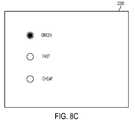
- FIG. 8Cis an illustration of an example of simple user interface for facilitating user controlled charging.
- FIG. 9is a diagram of an example of resource communication protocol.
- FIG. 10is a flow chart of an example of a smart charging customer guarantee.
- FIG. 11is a flow chart of an example of a smart charging benefit analysis.
- a systemcommunicates over the Internet and/or some other public or private networks with numerous individual electric resources connected to a power grid (hereinafter, “grid”). By communicating, the system can dynamically aggregate these electric resources to provide power services to grid operators (e.g. utilities, Independent System Operators (ISO), etc).
- grid operatorse.g. utilities, Independent System Operators (ISO), etc.
- Power servicesrefers to energy delivery as well as other ancillary services including demand response, regulation, spinning reserves, non-spinning reserves, energy imbalance, reactive power, and similar products.
- Aggregationrefers to the ability to control power flows into and out of a set of spatially distributed electric resources with the purpose of providing a power service of larger magnitude.
- Charge Control Managementrefers to enabling or performing the starting, stopping, or level-setting of a flow of power between a power grid and an electric resource.
- Power grid operatorrefers to the entity that is responsible for maintaining the operation and stability of the power grid within or across an electric control area.
- the power grid operatormay constitute some combination of manual/human action/intervention and automated processes controlling generation signals in response to system sensors.
- a “control area operator”is one example of a power grid operator.
- Control arearefers to a contained portion of the electrical grid with defined input and output ports. The net flow of power into this area must equal (within some error tolerance) the sum of the power consumption within the area and power outflow from the area, less the power production within in the area.
- Power gridas used herein means a power distribution system/network that connects producers of power with consumers of power.
- the networkmay include generators, transformers, interconnects, switching stations, and safety equipment as part of either/both the transmission system (i.e., bulk power) or the distribution system (i.e. retail power).
- the power aggregation systemis vertically scalable for use within a neighborhood, a city, a sector, a control area, or (for example) one of the eight large-scale Interconnects in the North American Electric Reliability Council (NERC).
- the systemis horizontally scalable for use in providing power services to multiple grid areas simultaneously.
- Grid conditionsrefers to the need for more or less power flowing in or out of a section of the electric power grid, in response to one of a number of conditions, for example supply changes, demand changes, contingencies and failures, ramping events, etc. These grid conditions typically manifest themselves as power quality events such as under- or over-voltage events or under- or over-frequency events.
- Power quality eventstypically refers to manifestations of power grid instability including voltage deviations and frequency deviations; additionally, power quality events as used herein also includes other disturbances in the quality of the power delivered by the power grid such as sub-cycle voltage spikes and harmonics.
- Electric resourcetypically refers to electrical entities that can be commanded to do some or all of these three things: take power (act as load), provide power (act as power generation or source), and store energy. Examples may include battery/charger/inverter systems for electric or hybrid-electric vehicles, repositories of used-but-serviceable electric vehicle batteries, fixed energy storage, fuel cell generators, emergency generators, controllable loads, etc.
- Electric vehicleis used broadly herein to refer to pure electric and hybrid electric vehicles, such as plug-in hybrid electric vehicles (PHEVs), especially vehicles that have significant storage battery capacity and that connect to the power grid for recharging the battery. More specifically, electric vehicle means a vehicle that gets some or all of its energy for motion and other purposes from the power grid. Moreover, an electric vehicle has an energy storage system, which may consist of batteries, capacitors, etc., or some combination thereof. An electric vehicle may or may not have the capability to provide power back to the electric grid.
- PHEVsplug-in hybrid electric vehicles
- Electric vehicle “energy storage systems”(batteries, super capacitors, and/or other energy storage devices) are used herein as a representative example of electric resources intermittently or permanently connected to the grid that can have dynamic input and output of power. Such batteries can function as a power source or a power load.
- a collection of aggregated electric vehicle batteriescan become a statistically stable resource across numerous batteries, despite recognizable tidal connection trends (e.g., an increase in the total number of vehicles connected to the grid at night; a downswing in the collective number of connected batteries as the morning commute begins, etc.)
- connection trendsare predictable and such batteries become a stable and reliable resource to call upon, should the grid or a part of the grid (such as a person's home in a blackout) experience a need for increased or decreased power.
- Data collection and storagealso enable the power aggregation system to predict connection behavior on a per-user basis.
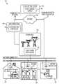
- FIG. 1shows a power aggregation system 100 .
- a flow control center 102is communicatively coupled with a network, such as a public/private mix that includes the Internet 104 , and includes one or more servers 106 providing a centralized power aggregation service.
- Internet 104will be used herein as representative of many different types of communicative networks and network mixtures (e.g., one or more wide area networks—public or private—and/or one or more local area networks).
- the flow control center 102maintains communication 108 with operators of power grid(s), and communication 110 with remote resources, i.e., communication with peripheral electric resources 112 (“end” or “terminal” nodes/devices of a power network) that are connected to the power grid 114 .
- power line communicatorssuch as those that include or consist of Ethernet-over-power line bridges 120 are implemented at connection locations so that the “last mile” (in this case, last feet—e.g., in a residence 124 ) of Internet communication with remote resources is implemented over the same wire that connects each electric resource 112 to the power grid 114 .
- each physical location of each electric resource 112may be associated with a corresponding Ethernet-over-power line bridge 120 (hereinafter, “bridge”) at or near the same location as the electric resource 112 .
- Each bridge 120is typically connected to an Internet access point of a location owner, as will be described in greater detail below.
- the communication medium from flow control center 102 to the connection location, such as residence 124can take many forms, such as cable modem, DSL, satellite, fiber, WiMax, etc.
- electric resources 112may connect with the Internet by a different medium than the same power wire that connects them to the power grid 114 .
- a given electric resource 112may have its own wireless capability to connect directly with the Internet 104 or an Internet access point and thereby with the flow control center 102 .
- Electric resources 112 of the power aggregation system 100may include the batteries of electric vehicles connected to the power grid 114 at residences 124 , parking lots 126 etc.; batteries in a repository 128 , fuel cell generators, private dams, conventional power plants, and other resources that produce electricity and/or store electricity physically or electrically.
- each participating electric resource 112 or group of local resourceshas a corresponding remote intelligent power flow (IPF) module 134 (hereinafter, “remote IPF module” 134 ).
- the centralized flow control center 102administers the power aggregation system 100 by communicating with the remote IPF modules 134 distributed peripherally among the electric resources 112 .
- the remote IPF modules 134perform several different functions, including, but not limited to, providing the flow control center 102 with the statuses of remote resources; controlling the amount, direction, and timing of power being transferred into or out of a remote electric resource 112 ; providing metering of power being transferred into or out of a remote electric resource 112 ; providing safety measures during power transfer and changes of conditions in the power grid 114 ; logging activities; and providing self-contained control of power transfer and safety measures when communication with the flow control center 102 is interrupted.
- the remote IPF modules 134will be described in greater detail below.
- each electric resource 112may have a corresponding transceiver (not shown) to communicate with a local charging component (not shown).
- the transceiver and charging componentin combination, may communicate with flow control center 102 to perform some or all of the above mentioned functions of IPF module 134 .
- a transceiver and charging componentare shown in FIG. 2B and are described in greater detail herein.
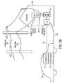
- FIG. 2Ashows another view of electrical and communicative connections to an electric resource 112 .
- an electric vehicle 200includes a battery bank 202 and a remote IPF module 134 .
- the electric vehicle 200may connect to a conventional wall receptacle (wall outlet) 204 of a residence 124 , the wall receptacle 204 representing the peripheral edge of the power grid 114 connected via a residential powerline 206 .
- the power cord 208 between the electric vehicle 200 and the wall outlet 204can be composed of only conventional wire and insulation for conducting alternating current (AC) power to and from the electric vehicle 200 .
- a location-specific connection locality module 210performs the function of network access point—in this case, the Internet access point.
- a bridge 120intervenes between the receptacle 204 and the network access point so that the power cord 208 can also carry network communications between the electric vehicle 200 and the receptacle 204 .
- connection locality module 210With such a bridge 120 and connection locality module 210 in place in a connection location, no other special wiring or physical medium is needed to communicate with the remote IPF module 134 of the electric vehicle 200 other than a conventional power cord 208 for providing residential line current at any conventional voltage. Upstream of the connection locality module 210 , power and communication with the electric vehicle 200 are resolved into the powerline 206 and an Internet cable 104 .
- the power cord 208may include safety features not found in conventional power and extension cords.
- an electrical plug 212 of the power cord 208may include electrical and/or mechanical safeguard components to prevent the remote IPF module 134 from electrifying or exposing the male conductors of the power cord 208 when the conductors are exposed to a human user.
- a radio frequency (RF) bridgemay assist the remote IPF module 134 in communicating with a foreign system, such as a utility smart meter (not shown) and/or a connection locality module 210 .
- the remote IPF module 134may be equipped to communicate over power cord 208 or to engage in some form of RF communication, such as Zigbee or Bluetooth, and the foreign system may be able to engage in a different form of RF communication.
- the RF bridgemay be equipped to communicate with both the foreign system and remote IPF module 134 and to translate communications from one to a form the other may understand, and to relay those messages.
- the RF bridgemay be integrated into the remote IPF module 134 or foreign system, or may be external to both.
- the communicative associations between the RF bridge and remote IPF module 134 and between the RF bridge and foreign systemmay be via wired or wireless communication.
- FIG. 2Bshows a further view of electrical and communicative connections to an electric resource 112 .
- the electric vehicle 200may include a transceiver 212 rather than a remote IPF module 134 .
- the transceiver 212may be communicatively coupled to a charging component 214 through a connection 216 , and the charging component itself may be coupled to a conventional wall receptacle (wall outlet) 204 of a residence 124 and to electric vehicle 200 through a power cord 208 .
- the other components shown in FIG. 2Bmay have the couplings and functions discussed with regard to FIG. 2A .
- transceiver 212 and charging component 214may, in combination, perform the same functions as the remote IPF module 134 .
- Transceiver 212may interface with computer systems of electric vehicle 200 and communicate with charging component 214 , providing charging component 214 with information about electric vehicle 200 , such as its vehicle identifier, a location identifier, and a state of charge.
- transceiver 212may receive requests and commands which transceiver 212 may relay to vehicle 200 's computer systems.
- Charging component 214may effectuate charge control of the electric vehicle 200 . If the electric vehicle 200 is not capable of charge control management, charging component 214 may directly manage the charging of electric vehicle 200 by stopping and starting a flow of power between the electric vehicle 200 and a power grid 114 in response to commands received from a flow control server 106 . If, on the other hand, the electric vehicle 200 is capable of charge control management, charging component 214 may effectuate charge control by sending commands to the electric vehicle 200 through the transceiver 212 .
- the transceiver 212may be physically coupled to the electric vehicle 200 through a data port, such as an OBD-II connector. In other embodiments, other couplings may be used.
- the connection 216 between transceiver 212 and charging component 214may be a wireless signal, such as a radio frequency (RF), such as a Zigbee or Bluetooth signal.
- charging component 214may include a receiver socket to couple with power cord 208 and a plug to couple with wall outlet 204 .
- charging component 214may be coupled to connection locality module 210 in either a wired or wireless fashion.
- charging component 214might have a data interface for communicating wirelessly with both the transceiver 212 and locality module 210 . In such an embodiment, the bridge 120 may not be required.
- transceiver 212 and charging component 214Further details about the transceiver 212 and charging component 214 are illustrated by FIG. 8B and described in greater detail herein.
- FIG. 3shows another implementation of the connection locality module 210 of FIG. 2 , in greater detail.
- an electric resource 112has an associated remote IPF module 134 , including a bridge 120 .
- the power cord 208connects the electric resource 112 to the power grid 114 and also to the connection locality module 210 in order to communicate with the flow control server 106 .
- the connection locality module 210includes another instance of a bridge 120 , connected to a network access point 302 , which may include such components as a router, switch, and/or modem, to establish a hardwired or wireless connection with, in this case, the Internet 104 .
- the power cord 208 between the two bridges 120 and 120 ′is replaced by a wireless Internet link, such as a wireless transceiver in the remote IPF module 134 and a wireless router in the connection locality module 210 .
- a transceiver 212 and charging component 214may be used instead of a remote IPF module 134 .
- the charging component 214may include or be coupled to a bridge 120
- the connection locality module 210may also include a bridge 120 ′, as shown.
- charging component 214 and connection locality module 210may communicate in a wired or wireless fashion, as mentioned previously, without bridges 120 and 120 ′.
- the wired or wireless communicationmay utilize any sort of connection technology known in the art, such as Ethernet or RF communication, such as Zigbee, or Bluetooth.
- FIG. 4shows a layout 400 of the power aggregation system 100 .
- the flow control center 102can be connected to many different entities, e.g., via the Internet 104 , for communicating and receiving information.
- the layout 400includes electric resources 112 , such as plug-in electric vehicles 200 , physically connected to the grid within a single control area 402 .
- the electric resources 112become an energy resource for grid operators 404 to utilize.
- the layout 400also includes end users 406 classified into electric resource owners 408 and electrical connection location owners 410 , who may or may not be one and the same.
- the stakeholders in a power aggregation system 100include the system operator at the flow control center 102 , the grid operator 404 , the resource owner 408 , and the owner of the location 410 at which the electric resource 112 is connected to the power grid 114 .
- Electrical connection location owners 410can include:
- Rental car lots—rental car companies often have a large portion of their fleet parked in the lot. They can purchase fleets of electric vehicles 200 and, participating in a power aggregation system 100 , generate revenue from idle fleet vehicles.
- Residencesa home garage can merely be equipped with a connection locality module 210 to enable the homeowner to participate in the power aggregation system 100 and generate revenue from a parked car. Also, the vehicle battery 202 and associated power electronics within the vehicle can provide local power backup power during times of peak load or power outages.
- the grid operations 116 of FIG. 4collectively include interactions with energy markets 412 , the interactions of grid operators 404 , and the interactions of automated grid controllers 118 that perform automatic physical control of the power grid 114 .
- the flow control center 102may also be coupled with information sources 414 for input of weather reports, events, price feeds, etc.
- Other data sources 414include the system stakeholders, public databases, and historical system data, which may be used to optimize system performance and to satisfy constraints on the power aggregation system 100 .
- a power aggregation system 100may consist of components that:
- These componentscan be running on a single computing resource (computer, etc.), or on a distributed set of resources (either physically co-located or not).
- Power aggregation systems 100 in such a layout 400can provide many benefits: for example, lower-cost ancillary services (i.e., power services), fine-grained (both temporal and spatial) control over resource scheduling, guaranteed reliability and service levels, increased service levels via intelligent resource scheduling, and/or firming of intermittent generation sources such as wind and solar power generation.
- the power aggregation system 100enables a grid operator 404 to control the aggregated electric resources 112 connected to the power grid 114 .
- An electric resource 112can act as a power source, load, or storage, and the resource 112 may exhibit combinations of these properties.
- Control of a set of electric resources 112is the ability to actuate power consumption, generation, or energy storage from an aggregate of these electric resources 112 .
- FIG. 5shows the role of multiple control areas 402 in the power aggregation system 100 .
- Each electric resource 112can be connected to the power aggregation system 100 within a specific electrical control area.
- a single instance of the flow control center 102can administer electric resources 112 from multiple distinct control areas 501 (e.g., control areas 502 , 504 , and 506 ).
- this functionalityis achieved by logically partitioning resources within the power aggregation system 100 . For example, when the control areas 402 include an arbitrary number of control areas, control area “A” 502 , control area “B” 504 , . . .
- grid operations 116can include corresponding control area operators 508 , 510 , . . . , and 512 .
- Further division into a control hierarchy that includes control division groupings above and below the illustrated control areas 402allows the power aggregation system 100 to scale to power grids 114 of different magnitudes and/or to varying numbers of electric resources 112 connected with a power grid 114 .
- FIG. 6shows a layout 600 of a power aggregation system 100 that uses multiple centralized flow control centers 102 and 102 ′ and a directory server 602 for determining a flow control center.
- Each flow control center 102 and 102 ′has its own respective end users 406 and 406 ′.
- Control areas 402 to be administered by each specific instance of a flow control center 102can be assigned dynamically.
- a first flow control center 102may administer control area A 502 and control area B 504
- a second flow control center 102 ′administers control area n 506 .
- corresponding control area operators508 , 510 , and 512
- an electric resourcemay determine which flow control center 102 / 102 ′ administers its control area 502 / 504 / 506 by communicating with a directory server 602 .
- the address of the directory server 602may be known to electric resource 112 or its associated IPF module 134 or charging component 214 .
- the electric resource 112may communicate with the directory server 602 , providing the directory server 112 with a resource identifier and/or a location identifier. Based on this information, the directory server 602 may respond, identifying which flow control center 102 / 102 ′ to use.
- directory server 602may be integrated with a flow control server 106 of a flow control center 102 / 102 ′.
- the electric resource 112may contact the server 106 .
- the server 106may either interact with the electric resource 112 itself or forward the connection to another flow control center 102 / 102 ′ responsible for the location identifier provided by the electric resource 112 .
- directory server 602may include a publicly accessible database for mapping locations to flow control centers 102 / 102 ′.
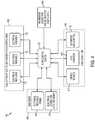
- FIG. 7shows a server 106 of the flow control center 102 .
- the illustrated implementation in FIG. 7is only one example configuration, for descriptive purposes. Many other arrangements of the illustrated components or even different components constituting a server 106 of the flow control center 102 are possible within the scope of the subject matter.
- Such a server 106 and flow control center 102can be executed in hardware, software, or combinations of hardware, software, firmware, etc.
- the flow control server 106includes a connection manager 702 to communicate with electric resources 112 , a prediction engine 704 that may include a learning engine 706 and a statistics engine 708 , a constraint optimizer 710 , and a grid interaction manager 712 to receive grid control signals 714 .
- Grid control signals 714are sometimes referred to as generation control signals, such as automated generation control (AGC) signals.
- AGCautomated generation control
- the flow control server 106may further include a database/information warehouse 716 , a web server 718 to present a user interface to electric resource owners 408 , grid operators 404 , and electrical connection location owners 410 ; a contract manager 720 to negotiate contract terms with energy markets 412 , and an information acquisition engine 414 to track weather, relevant news events, etc., and download information from public and private databases 722 for predicting behavior of large groups of the electric resources 112 , monitoring energy prices, negotiating contracts, etc.
- a database/information warehouse 716to present a user interface to electric resource owners 408 , grid operators 404 , and electrical connection location owners 410 ;
- a contract manager 720to negotiate contract terms with energy markets 412 , and an information acquisition engine 414 to track weather, relevant news events, etc., and download information from public and private databases 722 for predicting behavior of large groups of the electric resources 112 , monitoring energy prices, negotiating contracts, etc.
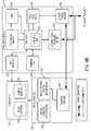
- FIG. 8Ashows the remote IPF module 134 of FIGS. 1 and 2 in greater detail.
- the illustrated remote IPF module 134is only one example configuration, for descriptive purposes. Many other arrangements of the illustrated components or even different components constituting a remote IPF module 134 are possible within the scope of the subject matter.
- Such a remote IPF module 134has some hardware components and some components that can be executed in hardware, software, or combinations of hardware, software, firmware, etc.
- executable instructions configured to perform some or all of the operations of remote IPF module 134may be added to hardware of an electric resource 112 such as an electric vehicle that, when combined with the executable instructions, provides equivalent functionality to remote IPF module 134 . References to remote IPF module 134 as used herein include such executable instructions.
- the illustrated example of a remote IPF module 134is represented by an implementation suited for an electric vehicle 200 .
- some vehicle systems 800are included as part of the remote IPF module 134 for the sake of description.
- the remote IPF module 134may exclude some or all of the vehicles systems 800 from being counted as components of the remote IPF module 134 .
- the depicted vehicle systems 800include a vehicle computer and data interface 802 , an energy storage system, such as a battery bank 202 , and an inverter/charger 804 .
- the remote IPF module 134also includes a communicative power flow controller 806 .
- the communicative power flow controller 806in turn includes some components that interface with AC power from the grid 114 , such as a powerline communicator, for example an Ethernet-over-powerline bridge 120 , and a current or current/voltage (power) sensor 808 , such as a current sensing transformer.
- the communicative power flow controller 806also includes Ethernet and information processing components, such as a processor 810 or microcontroller and an associated Ethernet media access control (MAC) address 812 ; volatile random access memory 814 , nonvolatile memory 816 or data storage, an interface such as an RS-232 interface 818 or a CANbus interface 820 ; an Ethernet physical layer interface 822 , which enables wiring and signaling according to Ethernet standards for the physical layer through means of network access at the MAC/Data Link Layer and a common addressing format.
- the Ethernet physical layer interface 822provides electrical, mechanical, and procedural interface to the transmission medium—i.e., in one implementation, using the Ethernet-over-powerline bridge 120 .
- wireless or other communication channels with the Internet 104are used in place of the Ethernet-over-powerline bridge 120 .
- the communicative power flow controller 806also includes a bidirectional power flow meter 824 that tracks power transfer to and from each electric resource 112 , in this case the battery bank 202 of an electric vehicle 200 .
- the communicative power flow controller 806operates either within, or connected to an electric vehicle 200 or other electric resource 112 to enable the aggregation of electric resources 112 introduced above (e.g., via a wired or wireless communication interface).
- These above-listed componentsmay vary among different implementations of the communicative power flow controller 806 , but implementations typically include:
- a user interfaceoptionally, a user interface.
- Implementations of the communicative power flow controller 806can enable functionality including:
- the communicative power flow controller 806includes a central processor 810 , interfaces 818 and 820 for communication within the electric vehicle 200 , a powerline communicator, such as an Ethernet-over-powerline bridge 120 for communication external to the electric vehicle 200 , and a power flow meter 824 for measuring energy flow to and from the electric vehicle 200 via a connected AC powerline 208 .
- a powerline communicatorsuch as an Ethernet-over-powerline bridge 120 for communication external to the electric vehicle 200
- a power flow meter 824for measuring energy flow to and from the electric vehicle 200 via a connected AC powerline 208 .
- Poweris the rate of energy consumption per interval of time. Power indicates the quantity of energy transferred during a certain period of time, thus the units of power are quantities of energy per unit of time.
- the power flow meter 824measures power for a given electric resource 112 across a bidirectional flow—e.g., power from grid 114 to electric vehicle 200 or from electric vehicle 200 to the grid 114 .
- the remote IPF module 134can locally cache readings from the power flow meter 824 to ensure accurate transactions with the central flow control server 106 , even if the connection to the server is down temporarily, or if the server itself is unavailable.
- FIG. 8Bshows the transceiver 212 and charging component 214 of FIG. 2B in greater detail.
- the illustrated transceiver 212 and charging component 214is only one example configuration, for descriptive purposes. Many other arrangements of the illustrated components or even different components constituting the transceiver 212 and charging component 214 are possible within the scope of the subject matter.
- Such a transceiver 212 and charging component 214have some hardware components and some components that can be executed in hardware, software, or combinations of hardware, software, firmware, etc.
- transceiver 212 and charging component 214is represented by an implementation suited for an electric vehicle 200 .
- vehicle systems 800are illustrated to provide context to the transceiver 212 and charging component 214 components.
- vehicle systems 800include a vehicle computer and data interface 802 , an energy storage system, such as a battery bank 202 , and an inverter/charger 804 .
- vehicle systems 800may include a data port, such as an OBD-II port, that is capable of physically coupling with the transceiver 212 .
- the transceiver 212may then communicate with the vehicle computer and data interface 802 through the data port, receiving information from electric resource 112 comprised by vehicle systems 800 and, in some embodiments, providing commands to the vehicle computer and data interface 802 .
- the vehicle computer and data interface 802may be capable of charge control management.
- the vehicle computer and data interface 802may perform some or all of the charging component 214 operations discussed below.
- executable instructions configured to perform some or all of the operations of the vehicle computer and data interface 802may be added to hardware of an electric resource 112 such as an electric vehicle that, when combined with the executable instructions, provides equivalent functionality to the vehicle computer and data interface 802 .
- References to the vehicle computer and data interface 802 as used hereininclude such executable instructions.
- the transceiver 212may have a physical form that is capable of coupling to a data port of vehicle systems 800 .
- a transceiver 212may also include a plurality of interfaces, such as an RS-232 interface 818 and/or a CANBus interface 820 .
- the RS-232 interface 818 or CANBus interface 820may enable the transceiver 212 to communicate with the vehicle computer and data interface 802 through the data port.
- the transceivermay be or comprise an additional interface (not shown) capable of engaging in wireless communication with a data interface 820 of the charging component 214 .
- the wireless communicationmay be of any form known in the art, such as radio frequency (RF) communication (e.g., Zigbee and/or Bluetooth communication).
- RFradio frequency
- the transceivermay comprise a separate conductor or may be configured to utilize a powerline 208 to communicate with charging component 214 .
- transceiver 212may simply be a radio frequency identification (RFID) tag capable of storing minimal information about the electric resource 112 , such as a resource identifier, and of being read by a corresponding RFID reader of charging component 214 .
- RFID tagmight not couple with a data port or communicate with the vehicle computer and data interface 802 .
- the charging component 214may be an intelligent plug device that is physically connected to a charging medium, such as a powerline 208 (the charging medium coupling the charging component 214 to the electric resource 112 ) and an outlet of a power grid (such as the wall outlet 204 shown in FIG. 2B ).
- a charging mediumsuch as a powerline 208 (the charging medium coupling the charging component 214 to the electric resource 112 ) and an outlet of a power grid (such as the wall outlet 204 shown in FIG. 2B ).
- charging component 214may be a charging station or some other external control.
- the charging component 214may be portable.
- the charging component 214may include components that interface with AC power from the grid 114 , such as a powerline communicator, for example an Ethernet-over-powerline bridge 120 , and a current or current/voltage (power) sensor 808 , such as a current sensing transformer.
- a powerline communicatorfor example an Ethernet-over-powerline bridge 120
- a current or current/voltage (power) sensor 808such as a current sensing transformer.
- the charging component 214may include a further Ethernet plug or wireless interface in place of bridge 120 .
- data-over-powerline communicationis not necessary, eliminating the need for a bridge 120 .
- the Ethernet plug or wireless interfacemay communicate with a local access point, and through that access point to flow control server 106 .
- the charging component 214may also include Ethernet and information processing components, such as a processor 810 or microcontroller and an associated Ethernet media access control (MAC) address 812 ; volatile random access memory 814 , nonvolatile memory 816 or data storage, a data interface 826 for communicating with the transceiver 212 , and an Ethernet physical layer interface 822 , which enables wiring and signaling according to Ethernet standards for the physical layer through means of network access at the MAC/Data Link Layer and a common addressing format.
- the Ethernet physical layer interface 822provides electrical, mechanical, and procedural interface to the transmission medium—i.e., in one implementation, using the Ethernet-over-powerline bridge 120 .
- wireless or other communication channels with the Internet 104are used in place of the Ethernet-over-powerline bridge 120 .
- the charging component 214may also include a bidirectional power flow meter 824 that tracks power transfer to and from each electric resource 112 , in this case the battery bank 202 of an electric vehicle 200 .
- the charging component 214may comprise an RFID reader to read the electric resource information from transceiver 212 when transceiver 212 is an RFID tag.
- the charging component 214may include a credit card reader to enable a user to identify the electric resource 112 by providing credit card information.
- a transceiver 212may not be necessary.
- the charging component 214may include a user interface, such as one of the user interfaces described in greater detail below.
- Implementations of the charging component 214can enable functionality including:
- An electrical charging stationwhether free or for pay, can be installed with a user interface that presents useful information to the user. Specifically, by collecting information about the grid 114 , the electric resource state, and the preferences of the user, the station can present information such as the current electricity price, the estimated recharge cost, the estimated time until recharge, the estimated payment for uploading power to the grid 114 (either total or per hour), etc.
- the information acquisition engine 414communicates with the electric resource 112 and with public and/or private data networks 722 to acquire the data used in calculating this information.
- the types of information gathered from the electric resource 112could include an electric resource identifier (resource ID) and state information like the state of charge of the electric resource 112 .
- the resource IDcould be used to obtain knowledge of the electric resource type and capabilities, preferences, etc. through lookup with the flow control server 106 .
- the charging station system including the UImight also gather grid-based information, such as current and future energy costs at the charging station.
- electric resources 112may receive charge control management via power aggregation system 100 .
- an override controlmay be provided to override charge control management and charge as soon as possible.
- the override controlmay be provided, in various embodiments, as a user interface mechanism of the remote IPF module 134 , the charging component 214 , of the electric resource (for example, if electric resource is a vehicle 200 , the user interface control may be integrated with dash controls of the vehicle 200 ) or even via a web page offered by flow control server 106 .
- the controlcould be presented, for example, as a button, a touch screen option, a web page, or some other UI mechanism.
- the UImay be the UI illustrated by FIG. 8C and discussed in greater detail below.
- the overridewould be a one-time override, only applying to a single plug-in session. Upon disconnecting and reconnecting, the user may again need to interact with the UI mechanism to override the charge control management.
- the usermay pay more to charge with the override on than under charge control management, thus providing an incentive for the user to accept charge control management.
- a cost differentialmay be displayed or rendered to the user in conjunction with or on the UI mechanism. This differential could take into account time-varying pricing, such as Time of Use (TOU), Critical Peak Pricing (CPP), and Real-Time Pricing (RTP) schemes, as discussed above, as well as any other incentives, discounts, or payments that might be forgone by not accepting charge control management.
- TOUTime of Use
- CPPCritical Peak Pricing
- RTPReal-Time Pricing
- a user interface mechanism of the remote IPF module 134 , the charging component 214 , of the electric resourcemay enable a user to enter and/or edit management preferences to affect charge control management of the user's electric resource 112 .
- the UI mechanismmay allow the user to enter/edit general preferences, such as whether charge control management is enabled, whether vehicle-to-grid power flow is enabled or whether the electric resource 112 should only be charged with clean/green power.
- the UI mechanismmay enable a user to prioritize relative desires for minimizing costs, maximizing payments (i.e., fewer charge periods for higher amounts), achieving a full state-of-charge for the electric resource 112 , charging as rapidly as possible, and/or charging in as environmentally-friendly a way as possible. Additionally, the UI mechanism may enable a user to provide a default schedule for when the electric resource will be used (for example, if resource 112 is a vehicle 200 , the schedule would be for when the vehicle 200 should be ready to drive).
- the UI mechanismmay enable the user to add or select special rules, such as a rule not to charge if a price threshold is exceeded or a rule to only use charge control management if it will earn the user at least a specified threshold of output. Charge control management may then be effectuated based on any part or all of these user entered preferences.
- FIG. 8Cillustrates a simple user interface (UI) which enables a user to control charging based on selecting among a limited number of high level preferences.
- UI 2300includes the categories “green”, “fast”, and “cheap” (with what is considered “green”, “fast”, and “cheap” varying from embodiment to embodiment).
- the categories shown in UI 2300are selected only for the sake of illustration and may instead includes these and/or any other categories applicable to electric resource 112 charging known in the art.
- the UI 2300may be very basic, using well known form controls such as radio buttons. In other embodiments, other graphic controls known in the art may be used.
- the general categoriesmay be mapped to specific charging behaviors, such as those discussed above, by a flow control server 106 .
- FIG. 9illustrates a resource communication protocol.
- a remote IPF module 134 or charging component 214may be in communication with a flow control server 106 over the Internet 104 or another networking fabric or combination of networking fabrics.
- a protocol specifying an order of messages and/or a format for messagesmay be used to govern the communications between the remote IPF module 134 or charging component 214 and flow control server 106 .
- the protocolmay include two channels, one for messages initiated by the remote IPF module 134 or charging component 214 and for replies to those messages from the flow control server 106 , and another channel for messages initiated by the flow control server 106 and for replies to those messages from the remote IPF module 134 or charging component 214 .
- the channelsmay be asynchronous with respect to each other (that is, initiation of messages on one channel may be entirely independent of initiation of messages on the other channel). However, each channel may itself be synchronous (that is, once a message is sent on a channel, another message may not be sent until a reply to the first message is received).
- the remote IPF module 134 or charging component 214may initiate communication 902 with the flow control server 106 .
- communication 902may be initiated when, for example, an electric resource 112 first plugs in/connects to the power grid 114 .
- communication 902may be initiated at another time or times.
- the initial message 902 governed by the protocolmay require, for example, one or more of an electric resource identifier, such as a MAC address, a protocol version used, and/or a resource identifier type.
- a connectionmay be established between the remote IPF module 134 or charging component 214 and flow control server 106 .
- the remote IPF module 134 or charging component 214may register with flow control server 106 through a subsequent communication 903 .
- Communication 903may include a location identifier scheme, a latitude, a longitude, a max power value that the remote IPF module 134 or charging component 214 can draw, a max power value that the remote IPF module 134 or charging component 214 can provide, a current power value, and/or a current state of charge.
- the protocolmay require or allow messages 904 from the flow control server 106 to the remote IPF module 134 or charging component 214 or messages 906 from remote IPF module 134 or charging component 214 to the flow control server 106 .
- the messages 904may include, for example, one or more of commands, messages, and/or updates. Such messages 904 may be provided at any time after the initial message 902 .
- messages 904may include a command setting, a power level and/or a ping to determine whether the remote IPF module 134 or charging component 214 is still connected.
- the messages 906may include, for example, status updates to the information provided in the registration message 903 . Such messages 906 may be provided at any time after the initial message 902 . In one embodiment, the messages 906 may be provided on a pre-determined time interval basis. In various embodiments, messages 906 may even be sent when the remote IPF module 134 or charging component 214 is connected, but not registered. Such messages 906 may include data that is stored by flow control server 106 for later processing. Also, in some embodiments, messages 904 may be provided in response to a message 902 or 906 .
- a key component of obtaining such consentis to provide a smart charging behavior guarantee to the owner of an electric resource.
- a well structured guaranteewill avoid inconveniencing the vehicle owner, but will still provide substantial flexibility with regard to power flow into, and/or out of, the vehicle.
- An example of such a smart charging behavior guaranteeincludes having an electric vehicle charge to a predetermined level within a set number of hours of plugging the electric vehicle into an electrical outlet.
- the guaranteemay be an agreement to charge the electric vehicle to level X (e.g. fully charged) within N (e.g. 10.5) hours of having been connected to a power grid.
- an electric vehicleis charged to level X by time Y, where time Y can be set by the user (e.g. every morning at 7 a.m.).
- time Ymay be inferred by the system based on predictions from past individual and/or aggregate behavior.
- the smart charging behavior guaranteeprohibits more than N hours of total non-charging time (i.e. total delay) before reaching level X during a charge session.
- the guaranteecan set a maximum of 3 hours of total non-charging time before the battery reaches the target level.
- the smart charging behavior guaranteeprohibits more than N hours of total non-charging time (i.e. total delay) before reaching level X during given time window. This may be across multiple charge sessions. For example, the guarantee can set a maximum of 3 hours of total non-charging time spread over all charging sessions occurring during a 24 hour period.
- the guaranteeprohibits more than N hours of total non-charging time (i.e. total delay) before reaching level X and/or no more than M non-charging events during given long time window.
- thismay be across multiple charge sessions, such as setting a maximum of 50 hours of total non-charging time, and/or 10 curtailment events, spread over a whole year.
- each time periode.g. 1 hour
- at least N % of the timeis set to be spent charging (e.g. at least 50% of each hour).
- the time spent chargingmay be static from hour to hour.
- the actual charging timemay be set to follow a curve over a time period, where the N % changes over the time periods (e.g. 20% the first hour, 30% the second hour, etc.).
- a charge optimization engineincorporates each customers' specific guarantee into a system-wide charging plan. This allows the system overall to achieve aggregate goals, which may include but are not limited to load shifting, demand response, load leveling, wind (or other renewable) smoothing or firming, providing spinning/non-spinning reserves, providing system regulation, or other energy or ancillary services.
- the guaranteemay potentially be structured to provide financial or other remediation to the vehicle owner if the terms are not met. For example, in such a case the owner could be given a payment (e.g. $20), or given free charging for a period of time (e.g. 1 week), or other similar forms of compensation.
- a time by which the vehicle charging must be completedincludes calculating, when a vehicle plugs in, the charging time needed to charge the vehicle to the goal level of state of charge.
- the delayable timeis: Max(((target_SOC ⁇ current_SOC)/100)*energy capacity/charging_rate, 0).
- the model Max(B ⁇ A, 0)calculates the amount of delayable time available for the purposes of smart charging. For example, if it will take 6 hours to charge to the desired level, and 10 hours are available, we have 4 hours of delayable time. More complex charging time models, such as non-linear models, could be utilized instead of the simple linear model.
- the delayable timemay shrink based on the amount of energy transferred out of the vehicle.
- the available delay for a given vehiclemay be used as input to a cost function that is used to select which vehicles to delay. The more delay available for a given vehicle, the more eligible it is for selection to be delayed, and vice versa. If no delay is available, the cost of selecting this vehicle for delay is infinite, and cannot be selected, or potentially based on the magnitude of the penalty for not meeting the guarantee.
- FIG. 10shows an embodiment of a smart charging customer guarantee.
- a charging behavior guaranteeis determined 1010 for an electric resource.
- the charging behavior guaranteecomprises a guaranteed charging schedule that matches a regular charging schedule of the electric resource.
- the guaranteed charging schedulemay provide for power flow flexibility.
- the charging behavior guaranteeis transmitted 1020 from a server to the electric resources.
- the charging behavior for electric resourcesare managed 1030 based partially on the guaranteed charging schedule.
- the charging behavior guaranteemay be determined by an energy management system, such as the power aggregation system 100 as shown in FIG. 1 and described above.
- the servermay be the flow control server 106 of the flow control center 102 .
- Energy management systemshave been developed for controlling the power draw of distributed electrical loads, such as electric vehicles. Such systems use various methods, such as load interruption, load reduction, and reverse energy flow, to reduce the impact of the load on the electric grid and the local distribution infrastructure.
- an energy management systemcould produce a user-readable representation of the impact of the system.
- the energy management systemcould calculate key energy flow values and compare them to the baseline that would have occurred without the intervention of the system. Because the baseline behavior would not actually occur in the presence of an active energy management system, the system would necessarily calculate a synthetic baseline from available information.
- the energy management systemcan demonstrate the modification effected to the load curve, the reduction in peak power demand, and the amount of load that was controllable for various purposes.
- the energy management systemcan use scheduled and predicted values to generate this information for the future. This allows a graphical, tabular, or other representation of the benefits of the energy management system that extends into the past and future.
- An example view that is usefulis the aggregate power drawn by a population of vehicles (and potentially other devices) over time, both actual past and future predicted given a particular smart charging regime in effect, and compare this to predicted past and future aggregate power given a different smart charging regime (such as unmanaged charging).
- a backwards in time looking synthetic baselinecan be created by taking the actual vehicle data in terms of time of plugin, state of charge at plugin, and so forth, and simulating the power flows that would have occurred under a different smart charging regime, or under unmanaged charging.
- forwards in time looking synthetic baselinemay be created by first using models that predict, per vehicle, the time and SOC at plugin, and duration of plugin, and then applying a given smart charging regime (possibly including unmanaged charging) to create a net power curve.
- FIG. 11shows an embodiment of a smart charging benefit analysis.
- a smart charging benefitis determined 1110 .
- the smart charging benefitis provided by an energy management system which manages electric resources.
- the smart charging benefitresults from the energy management system and benefits an electric resource.
- a benefit representation of the smart charging benefitis transmitted 1120 from a server to the electric resource.
- the charging behavior for electric resourcesare managed 1130 based partially on the smart charging benefit.
- the smart charging benefitmay be determined by an energy management system, such as the power aggregation system 100 as shown in FIG. 1 and described above.
- the servermay be the flow control server 106 of the flow control center 102 .
- a system that uses a smart charging benefit analysismay also utilize smart charging customer guarantees, as described above.
Landscapes
- Engineering & Computer Science (AREA)
- Power Engineering (AREA)
- Mechanical Engineering (AREA)
- Transportation (AREA)
- Business, Economics & Management (AREA)
- Strategic Management (AREA)
- Finance (AREA)
- Accounting & Taxation (AREA)
- Economics (AREA)
- General Business, Economics & Management (AREA)
- Health & Medical Sciences (AREA)
- Physics & Mathematics (AREA)
- General Physics & Mathematics (AREA)
- Theoretical Computer Science (AREA)
- Development Economics (AREA)
- Marketing (AREA)
- Public Health (AREA)
- Entrepreneurship & Innovation (AREA)
- Game Theory and Decision Science (AREA)
- Water Supply & Treatment (AREA)
- General Health & Medical Sciences (AREA)
- Human Resources & Organizations (AREA)
- Primary Health Care (AREA)
- Tourism & Hospitality (AREA)
- Life Sciences & Earth Sciences (AREA)
- Sustainable Development (AREA)
- Sustainable Energy (AREA)
- Charge And Discharge Circuits For Batteries Or The Like (AREA)
- Electric Propulsion And Braking For Vehicles (AREA)
Abstract
Description
Claims (20)
Priority Applications (2)
| Application Number | Priority Date | Filing Date | Title |
|---|---|---|---|
| US12/839,239US8346401B2 (en) | 2009-07-17 | 2010-07-19 | Smart charging value and guarantee application |
| US13/731,320US10843580B2 (en) | 2009-07-17 | 2012-12-31 | Systems and methods for smart charging techniques, value and guarantee |
Applications Claiming Priority (3)
| Application Number | Priority Date | Filing Date | Title |
|---|---|---|---|
| US22649709P | 2009-07-17 | 2009-07-17 | |
| US25627809P | 2009-10-29 | 2009-10-29 | |
| US12/839,239US8346401B2 (en) | 2009-07-17 | 2010-07-19 | Smart charging value and guarantee application |
Related Child Applications (1)
| Application Number | Title | Priority Date | Filing Date |
|---|---|---|---|
| US12/839,235Continuation-In-PartUS20110016063A1 (en) | 2009-07-17 | 2010-07-19 | System and methods for smart charging techniques |
Publications (2)
| Publication Number | Publication Date |
|---|---|
| US20110015799A1 US20110015799A1 (en) | 2011-01-20 |
| US8346401B2true US8346401B2 (en) | 2013-01-01 |
Family
ID=43465854
Family Applications (2)
| Application Number | Title | Priority Date | Filing Date |
|---|---|---|---|
| US12/839,239Active - Reinstated2031-03-16US8346401B2 (en) | 2009-07-17 | 2010-07-19 | Smart charging value and guarantee application |
| US12/839,235AbandonedUS20110016063A1 (en) | 2009-07-17 | 2010-07-19 | System and methods for smart charging techniques |
Family Applications After (1)
| Application Number | Title | Priority Date | Filing Date |
|---|---|---|---|
| US12/839,235AbandonedUS20110016063A1 (en) | 2009-07-17 | 2010-07-19 | System and methods for smart charging techniques |
Country Status (1)
| Country | Link |
|---|---|
| US (2) | US8346401B2 (en) |
Cited By (21)
| Publication number | Priority date | Publication date | Assignee | Title |
|---|---|---|---|---|
| US20120101642A1 (en)* | 2010-10-20 | 2012-04-26 | Huettinger Elektronik Gmbh + Co. Kg | Plasma and Induction Heating Power Supply Systems and Related Methods |
| US20120161701A1 (en)* | 2010-12-28 | 2012-06-28 | Kabushiki Kaisha Toshiba | Power control system |
| US20120179393A1 (en)* | 2003-06-13 | 2012-07-12 | Arad Measuring Technologies Ltd. | Meter Register and Remote Meter Reader Utilizing a Stepper Motor |
| US20120239453A1 (en)* | 2011-03-18 | 2012-09-20 | International Business Machines Corporation | Resource cost optimization system, method, and program |
| US20120249065A1 (en)* | 2011-04-01 | 2012-10-04 | Michael Bissonette | Multi-use energy management and conversion system including electric vehicle charging |
| US8725330B2 (en) | 2010-06-02 | 2014-05-13 | Bryan Marc Failing | Increasing vehicle security |
| US20140149332A1 (en)* | 2011-06-27 | 2014-05-29 | Nec Corporation | Action suggestion device, action suggestion system, action suggestion method, and program |
| US20140232327A1 (en)* | 2011-10-07 | 2014-08-21 | Nissan Motor Co., Ltd | Charger and method of controlling charger |
| US20170008413A1 (en)* | 2015-07-09 | 2017-01-12 | Powertree Services, Inc. | Grid integration with photovoltaic generation and electric vehicle charging |
| US9843187B2 (en) | 2014-11-05 | 2017-12-12 | Honda Motor Co., Ltd. | System and method for aggregating electric vehicle loads for demand response events |
| US9987940B2 (en) | 2014-09-16 | 2018-06-05 | Honda Motor Co., Ltd. | Priority based vehicle control strategy |
| US20190184850A1 (en)* | 2017-12-01 | 2019-06-20 | California Institute Of Technology | Optimization Framework and Methods for Adaptive EV Charging |
| US11135936B2 (en) | 2019-03-06 | 2021-10-05 | Fermata, LLC | Methods for using temperature data to protect electric vehicle battery health during use of bidirectional charger |
| US20210336464A1 (en)* | 2020-04-28 | 2021-10-28 | Intel Corporation | Inference based fast charging |
| US11171509B2 (en) | 2016-02-25 | 2021-11-09 | California Institute Of Technology | Adaptive charging network using adaptive charging stations for electric vehicles |
| US11345251B2 (en) | 2020-06-23 | 2022-05-31 | Toyota Motor North America, Inc. | Priority-based energy transfer |
| US11376981B2 (en) | 2019-02-08 | 2022-07-05 | California Institute Of Technology | Systems and methods for adaptive EV charging |
| US20230011000A1 (en)* | 2021-07-08 | 2023-01-12 | Enersys Delaware Inc. | Direct current fast charging systems with grid tied energy storage systems |
| US11760223B2 (en) | 2020-06-23 | 2023-09-19 | Toyota Motor North America, Inc. | Need-based energy sharing |
| US11926236B2 (en) | 2018-09-20 | 2024-03-12 | Cummins Inc. | Power charging control systems and methods for electric vehicles |
| US11958372B2 (en) | 2019-11-26 | 2024-04-16 | Fermata Energy Llc | Device for bi-directional power conversion and charging for use with electric vehicles |
Families Citing this family (109)
| Publication number | Priority date | Publication date | Assignee | Title |
|---|---|---|---|---|
| US8185250B2 (en)* | 2009-09-23 | 2012-05-22 | Peoplewave, Inc. | Power load control system for utility power system |
| US8558504B2 (en) | 2010-01-11 | 2013-10-15 | Leviton Manufacturing Co., Inc. | Electric vehicle supply equipment with timer |
| US9299093B2 (en)* | 2010-01-29 | 2016-03-29 | GM Global Technology Operations LLC | Method for charging a plug-in electric vehicle |
| JP2012019600A (en)* | 2010-07-07 | 2012-01-26 | Sony Corp | Charger and method for controlling charge |
| WO2012148596A1 (en) | 2011-04-29 | 2012-11-01 | Electric Transportation Engineering Corporation, D/B/A Ecotality North America | System for measuring electricity and method of providing and using the same |
| WO2012148597A1 (en) | 2011-04-29 | 2012-11-01 | Electric Transportation Engineering Corporation, D/B/A Ecotality North America | Device to facilitate moving an electrical cable of an electric vehicle charging station and method of providing the same |
| WO2012017936A1 (en)* | 2010-08-05 | 2012-02-09 | 三菱自動車工業株式会社 | Battery information output device for power supply/demand leveling system |
| US20120123604A1 (en)* | 2010-11-12 | 2012-05-17 | Nathan Bowman Littrell | Systems, methods, and apparatus for demand response of battery-powered devices |
| NL2005816C2 (en)* | 2010-12-03 | 2012-06-05 | Epyon B V | Method, system and device for charging an electric vehicle. |
| JP2012125063A (en)* | 2010-12-08 | 2012-06-28 | Sony Corp | Power management system |
| US8972074B2 (en)* | 2011-03-30 | 2015-03-03 | General Electric Company | System and method for optimal load planning of electric vehicle charging |
| WO2012134495A1 (en)* | 2011-04-01 | 2012-10-04 | Aerovironment, Inc. | Multi-use energy management and conversion system including electric vehicle charging |
| EP2709232A4 (en)* | 2011-05-11 | 2015-08-26 | Toyota Motor Co Ltd | LOAD CONTROL DEVICE, VEHICLE BEING EQUIPPED, AND LOAD CONTROL METHOD |
| JP6012144B2 (en)* | 2011-05-20 | 2016-10-25 | パナソニックエコソリューションズ電路株式会社 | Charge control system |
| US9300138B2 (en)* | 2011-06-07 | 2016-03-29 | Fujitsu Limited | System and method for managing power consumption |
| CN102324752B (en)* | 2011-06-17 | 2013-11-13 | 辽宁省电力有限公司 | Wind power generation-combined ordered charge and discharge coordinated control system of pure electric vehicle |
| ES2748199T3 (en) | 2011-07-26 | 2020-03-13 | Gogoro Inc | Apparatus, method and article for providing information on the availability of energy storage devices in an energy storage device collection, charging and dispensing machine |
| US10186094B2 (en) | 2011-07-26 | 2019-01-22 | Gogoro Inc. | Apparatus, method and article for providing locations of power storage device collection, charging and distribution machines |
| WO2013016570A1 (en)* | 2011-07-26 | 2013-01-31 | Gogoro, Inc. | Apparatus, method and article for authentication, security and control of power storage devices, such as batteries, based on user profiles |
| WO2013016540A1 (en)* | 2011-07-26 | 2013-01-31 | Gogoro, Inc. | Apparatus, method and article for collection, charging and distributing power storage devices, such as batteries |
| JP6026535B2 (en) | 2011-07-26 | 2016-11-16 | ゴゴロ インク | RESERVED POWER STORAGE DEVICE DEVICE, METHOD, AND ARTICLE FOR RESERVING A POWER STORAGE DEVICE IN A COLLECTION, CHARGING AND DISTRIBUTION MACHINE |
| JP6422119B2 (en) | 2011-07-26 | 2018-11-14 | ゴゴロ インク | Apparatus, method and article for redistributing a power storage device such as a battery between collection charge distribution devices |
| TWI486909B (en)* | 2011-07-26 | 2015-06-01 | 睿能創意公司 | Apparatus, method and article for providing vehicle diagnostic data |
| US8854013B2 (en)* | 2011-07-27 | 2014-10-07 | The Boeing Company | System for monitoring a battery charger |
| US8716882B2 (en) | 2011-07-28 | 2014-05-06 | Powerline Load Control Llc | Powerline communicated load control |
| US20130046411A1 (en)* | 2011-08-15 | 2013-02-21 | Siemens Corporation | Electric Vehicle Load Management |
| US8326467B2 (en)* | 2011-09-06 | 2012-12-04 | General Electric Company | Controller and method of controlling a power system |
| JP5873986B2 (en)* | 2011-09-20 | 2016-03-01 | パナソニックIpマネジメント株式会社 | Charging system, server device, and server device program |
| CN103947069B (en) | 2011-09-26 | 2017-04-26 | 日本电气株式会社 | Power connection control system and method |
| US9348381B2 (en) | 2011-10-19 | 2016-05-24 | Zeco Systems Pte Ltd | Methods and apparatuses for charging of electric vehicles |
| US10023062B2 (en)* | 2012-01-10 | 2018-07-17 | General Electric Company | Electric vehicle mobility modeling and energy resources scheduling |
| EP2805185B1 (en)* | 2012-01-17 | 2018-10-03 | Phoenix Contact GmbH & Co. KG | Method for operating a field device, field device and server for a wide-area automation network |
| EP2814687B1 (en)* | 2012-02-13 | 2019-04-10 | Accenture Global Services Limited | Electric vehicle distributed intelligence |
| US8588986B2 (en)* | 2012-02-24 | 2013-11-19 | Cra International, Inc. | Power transmission switching |
| US9045042B2 (en) | 2012-04-13 | 2015-06-02 | Toyota Motor Engineering & Manufacturing North America, Inc. | System and method for a one-time departure schedule setup for charging battery-electric vehicles |
| FR2989779B1 (en)* | 2012-04-19 | 2015-02-06 | Commissariat Energie Atomique | DEVICE FOR DETERMINING A CHARACTERISTIC OF A BATTERY AND METHOD FOR OPERATING SUCH A DEVICE |
| US9563215B2 (en) | 2012-07-14 | 2017-02-07 | Causam Energy, Inc. | Method and apparatus for actively managing electric power supply for an electric power grid |
| JP2014023232A (en)* | 2012-07-17 | 2014-02-03 | Toshiba Corp | Energy management device, energy management method, and energy management program |
| WO2014018504A2 (en)* | 2012-07-23 | 2014-01-30 | Cornell University | System and methods for large scale charging of electric vehicles |
| US8983669B2 (en) | 2012-07-31 | 2015-03-17 | Causam Energy, Inc. | System, method, and data packets for messaging for electric power grid elements over a secure internet protocol network |
| US8849715B2 (en) | 2012-10-24 | 2014-09-30 | Causam Energy, Inc. | System, method, and apparatus for settlement for participation in an electric power grid |
| US10861112B2 (en) | 2012-07-31 | 2020-12-08 | Causam Energy, Inc. | Systems and methods for advanced energy settlements, network-based messaging, and applications supporting the same on a blockchain platform |
| US10475138B2 (en) | 2015-09-23 | 2019-11-12 | Causam Energy, Inc. | Systems and methods for advanced energy network |
| US9513648B2 (en) | 2012-07-31 | 2016-12-06 | Causam Energy, Inc. | System, method, and apparatus for electric power grid and network management of grid elements |
| GB2505929A (en)* | 2012-09-14 | 2014-03-19 | Pod Point Holiding Ltd | Method and system for predictive load shedding on a power grid |
| US10284003B2 (en)* | 2012-10-09 | 2019-05-07 | General Electric Company | End-user based backup management |
| US20140100672A1 (en)* | 2012-10-09 | 2014-04-10 | General Electric Company | Utility Based Backup Management |
| CN102968098B (en)* | 2012-11-05 | 2014-12-10 | 清华大学 | Distributed optimization method of charging power of electric automobiles in aggregator |
| WO2014076918A1 (en)* | 2012-11-13 | 2014-05-22 | パナソニック株式会社 | Storage battery control device, storage battery control method, and storage battery system |
| KR101420234B1 (en)* | 2012-11-26 | 2014-08-21 | 한국전기연구원 | Periodically to relieve the accumulated energy int the energy storage device of automatic generation control signal generation method and system using the same operating system |
| EP2930822A4 (en)* | 2012-12-10 | 2016-08-10 | Nec Corp | Power router, power network system, method for controlling operation of power router, and non-temporary computer-readable medium storing program for controlling operation of power router |
| US9637016B2 (en)* | 2012-12-14 | 2017-05-02 | Agim GJINALI | Fast charging system for electric vehicles |
| US9438041B2 (en) | 2012-12-19 | 2016-09-06 | Bosch Energy Storage Solutions Llc | System and method for energy distribution |
| US9312698B2 (en) | 2012-12-19 | 2016-04-12 | Robert Bosch Gmbh | System and method for energy distribution |
| US9260031B2 (en) | 2013-03-15 | 2016-02-16 | International Business Machines Corporation | Distributed charging of electrical assets |
| US11075530B2 (en) | 2013-03-15 | 2021-07-27 | Gogoro Inc. | Modular system for collection and distribution of electric storage devices |
| WO2014143908A1 (en)* | 2013-03-15 | 2014-09-18 | Robert Bosch Gmbh | System and method for energy distribution |
| DE102013006254A1 (en)* | 2013-04-11 | 2014-10-16 | Audi Ag | Voltage release of a high voltage vehicle |
| CN103280822A (en)* | 2013-05-27 | 2013-09-04 | 东南大学 | Intelligent distribution network scheduling management system for charging behavior of electric automobile |
| EP2871749A1 (en)* | 2013-11-07 | 2015-05-13 | Alcatel Lucent | A method of managing the definition of at least one action in at least a portion of an electrical power grid |
| US20150158397A1 (en)* | 2013-12-05 | 2015-06-11 | Ford Global Technologies, Llc | Method and Apparatus for Predicting Electric Vehicle Energy Consumption |
| US9488493B2 (en) | 2014-01-16 | 2016-11-08 | Ford Global Technologies, Llc | Method and apparatus for electric vehicle trip and recharge planning |
| US9509159B2 (en)* | 2014-03-20 | 2016-11-29 | Nissan North America, Inc. | Systems and methods for decreasing peak energy consumption of a power consumer using vehicle battery capacity |
| DE102014206381A1 (en)* | 2014-04-03 | 2015-10-08 | Bayerische Motoren Werke Aktiengesellschaft | Charging system for electric vehicles |
| CN106605338B (en) | 2014-08-11 | 2019-07-16 | 睿能创意公司 | Multidirectional electric connector, plug and system |
| CN110481360B (en) | 2014-09-04 | 2023-06-16 | 睿能创意公司 | Charging module of portable electric energy storage device |
| DE102014113240A1 (en)* | 2014-09-15 | 2016-03-17 | Eemobility Gmbh | Device for charging an electrical energy storage device of a vehicle and use of such a device |
| US20160111905A1 (en)* | 2014-10-17 | 2016-04-21 | Elwha Llc | Systems and methods for charging energy storage devices |
| EP3024105A1 (en)* | 2014-11-24 | 2016-05-25 | Siemens Aktiengesellschaft | Method and system for controlling reactive power in an electric distribution network |
| CN104967112B (en)* | 2015-06-26 | 2017-03-01 | 上海电力学院 | Light stores up the direct-current micro-grid control method for coordinating of formula electric automobile charging station |
| US9977450B2 (en) | 2015-09-24 | 2018-05-22 | Fujitsu Limited | Micro-balance event resource selection |
| CN105244941A (en)* | 2015-09-28 | 2016-01-13 | 国网山东省电力公司济南供电公司 | Ordered charging method based on linear power flow model solution for electric automobile battery charging and replacing station |
| US10230241B1 (en)* | 2015-09-30 | 2019-03-12 | The United States Of America, As Represented By The Secretary Of The Navy | Self-optimizing hybrid power system |
| CN105678404B (en)* | 2015-12-30 | 2019-07-23 | 东北大学 | Based on online shopping electricity and dynamically associate the micro-grid load forecasting system and method for the factor |
| KR101866645B1 (en)* | 2016-06-30 | 2018-06-12 | 한국과학기술원 | Controlling apparatus and method for charging electric vehicles |
| CN108370167B (en) | 2016-08-23 | 2021-11-05 | 柏思科技有限公司 | Method and system for distributing power to multiple loads |
| CN113263945B (en)* | 2016-08-23 | 2023-08-18 | 柏思科技有限公司 | Method and system for powering multiple loads with current measurements |
| US10419243B2 (en) | 2016-09-09 | 2019-09-17 | Johnson Controls Technology Company | Smart gateway devices, systems and methods for providing communication between HVAC system networks |
| US10650621B1 (en) | 2016-09-13 | 2020-05-12 | Iocurrents, Inc. | Interfacing with a vehicular controller area network |
| US20180147944A1 (en)* | 2016-11-26 | 2018-05-31 | Henry Allen Perkins | Superaaacharge |
| US10793013B2 (en)* | 2017-01-27 | 2020-10-06 | Toyota Motor Engineering & Manufacturing North America, Inc. | Automatic timer cancellation for charging vehicle |
| JP6627802B2 (en)* | 2017-02-23 | 2020-01-08 | トヨタ自動車株式会社 | Vehicle and power transmission system |
| US10396581B2 (en) | 2017-04-06 | 2019-08-27 | International Business Machines Corporation | Managing peak power consumption for distributed assets using battery charging schedules |
| DE102017108579A1 (en)* | 2017-04-21 | 2018-10-25 | Wobben Properties Gmbh | Method for operating a charging station |
| DE102017209801A1 (en) | 2017-06-09 | 2018-12-13 | Bayerische Motoren Werke Aktiengesellschaft | A method for operating a plurality of technical units as a composite on an electrical distribution network and control device and electrical device |
| GB2578004A (en) | 2017-07-24 | 2020-04-15 | A T Kearney Ltd | Aggregating energy resources |
| US10525844B2 (en)* | 2017-09-22 | 2020-01-07 | Honda Motor Co., Ltd. | System and method for electric vehicle charging |
| CN107591810A (en)* | 2017-11-03 | 2018-01-16 | 中国南方电网有限责任公司 | AC-DC hybrid power grid multisystem control method for coordinating |
| US20190275893A1 (en)* | 2018-03-06 | 2019-09-12 | Wellen Sham | Intelligent charging network |
| CN108320064A (en)* | 2018-04-28 | 2018-07-24 | 国电南瑞南京控制系统有限公司 | A kind of electric vehicle cooperates with charging dual-layer optimization dispatching method with wind-powered electricity generation |
| GB2577853B (en) | 2018-06-22 | 2021-03-24 | Moixa Energy Holdings Ltd | Systems for machine learning, optimising and managing local multi-asset flexibility of distributed energy storage resources |
| CN109050284B (en)* | 2018-07-09 | 2020-06-09 | 华中科技大学 | Electric automobile charging and discharging electricity price optimization method considering V2G |
| US11196258B2 (en)* | 2018-08-03 | 2021-12-07 | Sacramento Municipal Utility District | Energy control and storage system for controlling power based on a load shape |
| DE102018131770A1 (en) | 2018-12-11 | 2020-06-18 | Innogy Se | Charging system for electric vehicles |
| CN111347912B (en)* | 2018-12-20 | 2023-09-05 | 勃姆巴迪尔运输有限公司 | System and method for adjusting a charge rate of a vehicle battery based on an expected passenger load |
| NO20190023A1 (en)* | 2019-01-07 | 2020-07-08 | Easee As | Electrical assembly for a charging station |
| US11135931B2 (en)* | 2019-05-28 | 2021-10-05 | GM Global Technology Operations LLC | System for charging a battery electric vehicle or a plugin hybrid vehicle using a mobile fuel cell |
| DE102019215839A1 (en)* | 2019-10-15 | 2021-04-15 | Vitesco Technologies GmbH | Method for electrically charging vehicle batteries for a group of vehicles |
| US11203268B2 (en)* | 2020-01-14 | 2021-12-21 | GM Global Technology Operations LLC | Method and apparatus for selecting a charging station |
| CN111222809B (en)* | 2020-03-30 | 2020-09-25 | 广东电网有限责任公司佛山供电局 | User electricity utilization reliability analysis method based on combination of model drive and data drive |
| US11642977B2 (en)* | 2020-07-09 | 2023-05-09 | Weave Grid, Inc. | Optimized charging of electric vehicles over distribution grid |
| CN112001544B (en)* | 2020-08-24 | 2024-05-24 | 南京德睿能源研究院有限公司 | Scheduling control method for participation of charging station resources in electric power peak regulation market |
| US12187153B2 (en)* | 2020-12-22 | 2025-01-07 | Ford Global Technologies, Llc | System for selecting electric vehicle charging power |
| US11554684B2 (en)* | 2021-02-17 | 2023-01-17 | AMPLY Power, Inc. | Aggregating capacity for depot charging |
| US12393888B2 (en)* | 2021-03-30 | 2025-08-19 | Honda Motor Co., Ltd. | Multi-objective electric vehicle charging scheduler with configurable objective hierarchy |
| US12420656B2 (en) | 2022-05-21 | 2025-09-23 | Toyota Motor North America, Inc. | Vehicle-based detection and management of electrical power |
| US11760224B1 (en)* | 2022-08-03 | 2023-09-19 | Electric Era Technologies, Inc. | Vehicle charging system |
| JP7677286B2 (en)* | 2022-08-25 | 2025-05-15 | トヨタ自動車株式会社 | management device |
| CN116923168B (en)* | 2023-06-21 | 2024-04-26 | 上海旋荣科技股份有限公司 | Charging pile electric energy dispatching system and dispatching method based on transformer substation networking |
Citations (12)
| Publication number | Priority date | Publication date | Assignee | Title |
|---|---|---|---|---|
| US5642270A (en) | 1991-08-01 | 1997-06-24 | Wavedriver Limited | Battery powered electric vehicle and electrical supply system |
| US6377028B1 (en)* | 1990-10-23 | 2002-04-23 | Texas Instruments Incorporated | System for charging monitoring batteries for a microprocessor based method |
| US20070127713A1 (en)* | 2005-11-04 | 2007-06-07 | Schley-May James T | Methods and apparatuses to provide fault monitoring for a network interface device |
| US20070203860A1 (en)* | 2006-02-24 | 2007-08-30 | Gridpoint, Inc. | Energy budget manager |
| US20070276583A1 (en)* | 2006-05-09 | 2007-11-29 | Dobeck Brian R | power management apparatus and methods for portable data terminals |
| US20070282495A1 (en)* | 2006-05-11 | 2007-12-06 | University Of Delaware | System and method for assessing vehicle to grid (v2g) integration |
| US20080039979A1 (en) | 2006-08-10 | 2008-02-14 | V2 Green Inc. | Smart Islanding and Power Backup in a Power Aggregation System for Distributed Electric Resources |
| US20080185432A1 (en)* | 2007-02-01 | 2008-08-07 | Caballero Aldo M | Apparatus and methods for monitoring one or more portable data terminals |
| US20080281663A1 (en)* | 2007-05-09 | 2008-11-13 | Gridpoint, Inc. | Method and system for scheduling the discharge of distributed power storage devices and for levelizing dispatch participation |
| US20100039062A1 (en)* | 2008-08-18 | 2010-02-18 | Gong-En Gu | Smart charge system for electric vehicles integrated with alternative energy sources and energy storage |
| US20100179704A1 (en)* | 2009-01-14 | 2010-07-15 | Integral Analytics, Inc. | Optimization of microgrid energy use and distribution |
| US7886166B2 (en) | 2007-09-13 | 2011-02-08 | Gridpoint, Inc. | User interface for demand side energy management |
Family Cites Families (8)
| Publication number | Priority date | Publication date | Assignee | Title |
|---|---|---|---|---|
| US5274571A (en)* | 1991-05-20 | 1993-12-28 | The Fleming Group | Energy storage scheduling system |
| JP3554057B2 (en)* | 1995-02-06 | 2004-08-11 | 本田技研工業株式会社 | Battery charging control device for electric vehicles |
| US20080052145A1 (en)* | 2006-08-10 | 2008-02-28 | V2 Green, Inc. | Power Aggregation System for Distributed Electric Resources |
| US7679336B2 (en)* | 2007-02-27 | 2010-03-16 | Ford Global Technologies, Llc | Interactive battery charger for electric vehicle |
| US9457791B2 (en)* | 2009-01-06 | 2016-10-04 | GM Global Technology Operations LLC | Charging cable with controller |
| US8054048B2 (en)* | 2007-10-04 | 2011-11-08 | GM Global Technology Operations LLC | Power grid load management for plug-in vehicles |
| US8558511B2 (en)* | 2009-04-07 | 2013-10-15 | Battelle Memorial Institute | Method and apparatus for smart battery charging including a plurality of controllers each monitoring input variables |
| US8478452B2 (en)* | 2010-04-06 | 2013-07-02 | Battelle Memorial Institute | Grid regulation services for energy storage devices based on grid frequency |
- 2010
- 2010-07-19USUS12/839,239patent/US8346401B2/enactiveActive - Reinstated
- 2010-07-19USUS12/839,235patent/US20110016063A1/ennot_activeAbandoned
Patent Citations (12)
| Publication number | Priority date | Publication date | Assignee | Title |
|---|---|---|---|---|
| US6377028B1 (en)* | 1990-10-23 | 2002-04-23 | Texas Instruments Incorporated | System for charging monitoring batteries for a microprocessor based method |
| US5642270A (en) | 1991-08-01 | 1997-06-24 | Wavedriver Limited | Battery powered electric vehicle and electrical supply system |
| US20070127713A1 (en)* | 2005-11-04 | 2007-06-07 | Schley-May James T | Methods and apparatuses to provide fault monitoring for a network interface device |
| US20070203860A1 (en)* | 2006-02-24 | 2007-08-30 | Gridpoint, Inc. | Energy budget manager |
| US20070276583A1 (en)* | 2006-05-09 | 2007-11-29 | Dobeck Brian R | power management apparatus and methods for portable data terminals |
| US20070282495A1 (en)* | 2006-05-11 | 2007-12-06 | University Of Delaware | System and method for assessing vehicle to grid (v2g) integration |
| US20080039979A1 (en) | 2006-08-10 | 2008-02-14 | V2 Green Inc. | Smart Islanding and Power Backup in a Power Aggregation System for Distributed Electric Resources |
| US20080185432A1 (en)* | 2007-02-01 | 2008-08-07 | Caballero Aldo M | Apparatus and methods for monitoring one or more portable data terminals |
| US20080281663A1 (en)* | 2007-05-09 | 2008-11-13 | Gridpoint, Inc. | Method and system for scheduling the discharge of distributed power storage devices and for levelizing dispatch participation |
| US7886166B2 (en) | 2007-09-13 | 2011-02-08 | Gridpoint, Inc. | User interface for demand side energy management |
| US20100039062A1 (en)* | 2008-08-18 | 2010-02-18 | Gong-En Gu | Smart charge system for electric vehicles integrated with alternative energy sources and energy storage |
| US20100179704A1 (en)* | 2009-01-14 | 2010-07-15 | Integral Analytics, Inc. | Optimization of microgrid energy use and distribution |
Non-Patent Citations (1)
| Title |
|---|
| International Search Report No. PCT/US2010/0029491, dated Sep. 1, 2010, 1 page. |
Cited By (38)
| Publication number | Priority date | Publication date | Assignee | Title |
|---|---|---|---|---|
| US20120179393A1 (en)* | 2003-06-13 | 2012-07-12 | Arad Measuring Technologies Ltd. | Meter Register and Remote Meter Reader Utilizing a Stepper Motor |
| US8448845B2 (en)* | 2003-06-13 | 2013-05-28 | Arad Measuring Technologies Ltd. | Meter register and remote meter reader utilizing a stepper motor |
| US9114719B1 (en) | 2010-06-02 | 2015-08-25 | Bryan Marc Failing | Increasing vehicle security |
| US9393878B1 (en) | 2010-06-02 | 2016-07-19 | Bryan Marc Failing | Energy transfer with vehicles |
| US10124691B1 (en) | 2010-06-02 | 2018-11-13 | Bryan Marc Failing | Energy transfer with vehicles |
| US11186192B1 (en) | 2010-06-02 | 2021-11-30 | Bryan Marc Failing | Improving energy transfer with vehicles |
| US8725330B2 (en) | 2010-06-02 | 2014-05-13 | Bryan Marc Failing | Increasing vehicle security |
| US8841881B2 (en) | 2010-06-02 | 2014-09-23 | Bryan Marc Failing | Energy transfer with vehicles |
| US9503006B2 (en)* | 2010-10-20 | 2016-11-22 | Trumpf Huettinger Gmbh + Co. Kg | Plasma and induction heating power supply systems and related methods |
| US20120101642A1 (en)* | 2010-10-20 | 2012-04-26 | Huettinger Elektronik Gmbh + Co. Kg | Plasma and Induction Heating Power Supply Systems and Related Methods |
| US20120161701A1 (en)* | 2010-12-28 | 2012-06-28 | Kabushiki Kaisha Toshiba | Power control system |
| US20120239453A1 (en)* | 2011-03-18 | 2012-09-20 | International Business Machines Corporation | Resource cost optimization system, method, and program |
| US9092832B2 (en)* | 2011-03-18 | 2015-07-28 | International Business Machines Corporation | Resource cost optimization system, method, and program |
| US9196010B2 (en)* | 2011-03-18 | 2015-11-24 | International Business Machines Corporation | Resource cost optimization system, method, and program |
| US20130346345A1 (en)* | 2011-03-18 | 2013-12-26 | International Business Machines Corporation | Resource cost optimization system, method, and program |
| US20120249065A1 (en)* | 2011-04-01 | 2012-10-04 | Michael Bissonette | Multi-use energy management and conversion system including electric vehicle charging |
| US20140149332A1 (en)* | 2011-06-27 | 2014-05-29 | Nec Corporation | Action suggestion device, action suggestion system, action suggestion method, and program |
| US20140232327A1 (en)* | 2011-10-07 | 2014-08-21 | Nissan Motor Co., Ltd | Charger and method of controlling charger |
| US9376030B2 (en)* | 2011-10-07 | 2016-06-28 | Nissan Motor Co., Ltd. | Charger and method of controlling charger |
| US9987940B2 (en) | 2014-09-16 | 2018-06-05 | Honda Motor Co., Ltd. | Priority based vehicle control strategy |
| US9843187B2 (en) | 2014-11-05 | 2017-12-12 | Honda Motor Co., Ltd. | System and method for aggregating electric vehicle loads for demand response events |
| US10005371B2 (en)* | 2015-07-09 | 2018-06-26 | Powertree Services, Inc. | Grid integration with photovoltaic generation and electric vehicle charging |
| US20170008413A1 (en)* | 2015-07-09 | 2017-01-12 | Powertree Services, Inc. | Grid integration with photovoltaic generation and electric vehicle charging |
| US11171509B2 (en) | 2016-02-25 | 2021-11-09 | California Institute Of Technology | Adaptive charging network using adaptive charging stations for electric vehicles |
| US20190184850A1 (en)* | 2017-12-01 | 2019-06-20 | California Institute Of Technology | Optimization Framework and Methods for Adaptive EV Charging |
| US10926659B2 (en)* | 2017-12-01 | 2021-02-23 | California Institute Of Technology | Optimization framework and methods for adaptive EV charging |
| US11926236B2 (en) | 2018-09-20 | 2024-03-12 | Cummins Inc. | Power charging control systems and methods for electric vehicles |
| US12280689B2 (en) | 2018-09-20 | 2025-04-22 | Cummins Inc. | Power charging control systems and methods for electric vehicles |
| US11376981B2 (en) | 2019-02-08 | 2022-07-05 | California Institute Of Technology | Systems and methods for adaptive EV charging |
| US11135936B2 (en) | 2019-03-06 | 2021-10-05 | Fermata, LLC | Methods for using temperature data to protect electric vehicle battery health during use of bidirectional charger |
| US11958376B2 (en) | 2019-03-06 | 2024-04-16 | Fermata Energy Llc | Methods for using cycle life data to protect electric vehicle battery health during use of bidirectional charger |
| US11958372B2 (en) | 2019-11-26 | 2024-04-16 | Fermata Energy Llc | Device for bi-directional power conversion and charging for use with electric vehicles |
| US20210336464A1 (en)* | 2020-04-28 | 2021-10-28 | Intel Corporation | Inference based fast charging |
| US11345251B2 (en) | 2020-06-23 | 2022-05-31 | Toyota Motor North America, Inc. | Priority-based energy transfer |
| US11708001B2 (en) | 2020-06-23 | 2023-07-25 | Toyota Motor North America, Inc. | Priority-based energy transfer |
| US11760223B2 (en) | 2020-06-23 | 2023-09-19 | Toyota Motor North America, Inc. | Need-based energy sharing |
| US12109905B2 (en) | 2020-06-23 | 2024-10-08 | Toyota Motor North America, Inc. | Priority-based energy transfer |
| US20230011000A1 (en)* | 2021-07-08 | 2023-01-12 | Enersys Delaware Inc. | Direct current fast charging systems with grid tied energy storage systems |
Also Published As
| Publication number | Publication date |
|---|---|
| US20110015799A1 (en) | 2011-01-20 |
| US20110016063A1 (en) | 2011-01-20 |
Similar Documents
| Publication | Publication Date | Title |
|---|---|---|
| US8346401B2 (en) | Smart charging value and guarantee application | |
| US10843580B2 (en) | Systems and methods for smart charging techniques, value and guarantee | |
| US10906423B2 (en) | Power aggregation system for distributed electric resources | |
| US8781809B2 (en) | Software modeling systems for metering and translating measurements | |
| US10892639B2 (en) | Connection locator in a power aggregation system for distributed electric resources | |
| US7949435B2 (en) | User interface and user control in a power aggregation system for distributed electric resources | |
| US7747739B2 (en) | Connection locator in a power aggregation system for distributed electric resources | |
| US20080040223A1 (en) | Electric Resource Module in a Power Aggregation System for Distributed Electric Resources | |
| US20090043520A1 (en) | User Interface and User Control in a Power Aggregation System for Distributed Electric Resources | |
| US20080040263A1 (en) | Business Methods in a Power Aggregation System for Distributed Electric Resources | |
| US20080052145A1 (en) | Power Aggregation System for Distributed Electric Resources | |
| US20080040295A1 (en) | Power Aggregation System for Distributed Electric Resources | |
| WO2008073470A2 (en) | Electric resource module in a power aggregation system for distributed electric resources |
Legal Events
| Date | Code | Title | Description |
|---|---|---|---|
| STCF | Information on status: patent grant | Free format text:PATENTED CASE | |
| AS | Assignment | Owner name:MCHENRY LLC, NEW YORK Free format text:SECURITY AGREEMENT;ASSIGNOR:GRIDPOINT, INC.;REEL/FRAME:032133/0617 Effective date:20140128 | |
| FPAY | Fee payment | Year of fee payment:4 | |
| AS | Assignment | Owner name:GRIDPOINT, INC, VIRGINIA Free format text:SECURITY INTEREST;ASSIGNOR:MCHENRY LLC;REEL/FRAME:048834/0274 Effective date:20190402 | |
| AS | Assignment | Owner name:GRIDPOINT, INC, VIRGINIA Free format text:CORRECTIVE ASSIGNMENT TO CORRECT THE NATURE OF CONVEYANCE PREVIOUSLY RECORDED AT REEL: 048834 FRAME: 0274. ASSIGNOR(S) HEREBY CONFIRMS THE ASSIGNMENT;ASSIGNOR:MCHENRY LLC;REEL/FRAME:049009/0882 Effective date:20190402 Owner name:GRIDPOINT, INC, VIRGINIA Free format text:CORRECTIVE ASSIGNMENT TO CORRECT THE NATURE OF CONVEYANCE PREVIOUSLY RECORDED AT REEL: 048834 FRAME: 0274. ASSIGNOR(S) HEREBY CONFIRMS THE RELEASE OF SECURITY INTEREST;ASSIGNOR:MCHENRY LLC;REEL/FRAME:049009/0882 Effective date:20190402 | |
| FEPP | Fee payment procedure | Free format text:MAINTENANCE FEE REMINDER MAILED (ORIGINAL EVENT CODE: REM.); ENTITY STATUS OF PATENT OWNER: SMALL ENTITY | |
| LAPS | Lapse for failure to pay maintenance fees | Free format text:PATENT EXPIRED FOR FAILURE TO PAY MAINTENANCE FEES (ORIGINAL EVENT CODE: EXP.); ENTITY STATUS OF PATENT OWNER: SMALL ENTITY | |
| STCH | Information on status: patent discontinuation | Free format text:PATENT EXPIRED DUE TO NONPAYMENT OF MAINTENANCE FEES UNDER 37 CFR 1.362 | |
| FP | Lapsed due to failure to pay maintenance fee | Effective date:20210101 | |
| FEPP | Fee payment procedure | Free format text:SURCHARGE, PETITION TO ACCEPT PYMT AFTER EXP, UNINTENTIONAL. (ORIGINAL EVENT CODE: M2558); ENTITY STATUS OF PATENT OWNER: SMALL ENTITY Free format text:PETITION RELATED TO MAINTENANCE FEES GRANTED (ORIGINAL EVENT CODE: PMFG); ENTITY STATUS OF PATENT OWNER: SMALL ENTITY Free format text:PETITION RELATED TO MAINTENANCE FEES FILED (ORIGINAL EVENT CODE: PMFP); ENTITY STATUS OF PATENT OWNER: SMALL ENTITY | |
| MAFP | Maintenance fee payment | Free format text:PAYMENT OF MAINTENANCE FEE, 8TH YR, SMALL ENTITY (ORIGINAL EVENT CODE: M2552); ENTITY STATUS OF PATENT OWNER: SMALL ENTITY Year of fee payment:8 | |
| PRDP | Patent reinstated due to the acceptance of a late maintenance fee | Effective date:20210329 | |
| STCF | Information on status: patent grant | Free format text:PATENTED CASE | |
| AS | Assignment | Owner name:GRIDPOINT, INC., VIRGINIA Free format text:ASSIGNMENT OF ASSIGNORS INTEREST;ASSIGNOR:V2GREEN, INC.;REEL/FRAME:064341/0182 Effective date:20230719 | |
| FEPP | Fee payment procedure | Free format text:11.5 YR SURCHARGE- LATE PMT W/IN 6 MO, SMALL ENTITY (ORIGINAL EVENT CODE: M2556); ENTITY STATUS OF PATENT OWNER: SMALL ENTITY | |
| MAFP | Maintenance fee payment | Free format text:PAYMENT OF MAINTENANCE FEE, 12TH YR, SMALL ENTITY (ORIGINAL EVENT CODE: M2553); ENTITY STATUS OF PATENT OWNER: SMALL ENTITY Year of fee payment:12 |