US8346278B2 - Systems and methods for mobile phone location with digital distributed antenna systems - Google Patents
Systems and methods for mobile phone location with digital distributed antenna systemsDownload PDFInfo
- Publication number
- US8346278B2 US8346278B2US12/555,923US55592309AUS8346278B2US 8346278 B2US8346278 B2US 8346278B2US 55592309 AUS55592309 AUS 55592309AUS 8346278 B2US8346278 B2US 8346278B2
- Authority
- US
- United States
- Prior art keywords
- radio frequency
- digital
- signal
- unit
- subscriber
- Prior art date
- Legal status (The legal status is an assumption and is not a legal conclusion. Google has not performed a legal analysis and makes no representation as to the accuracy of the status listed.)
- Expired - Fee Related, expires
Links
Images


Classifications
- H—ELECTRICITY
- H04—ELECTRIC COMMUNICATION TECHNIQUE
- H04W—WIRELESS COMMUNICATION NETWORKS
- H04W4/00—Services specially adapted for wireless communication networks; Facilities therefor
- H04W4/02—Services making use of location information
- H—ELECTRICITY
- H04—ELECTRIC COMMUNICATION TECHNIQUE
- H04W—WIRELESS COMMUNICATION NETWORKS
- H04W24/00—Supervisory, monitoring or testing arrangements
- G—PHYSICS
- G01—MEASURING; TESTING
- G01S—RADIO DIRECTION-FINDING; RADIO NAVIGATION; DETERMINING DISTANCE OR VELOCITY BY USE OF RADIO WAVES; LOCATING OR PRESENCE-DETECTING BY USE OF THE REFLECTION OR RERADIATION OF RADIO WAVES; ANALOGOUS ARRANGEMENTS USING OTHER WAVES
- G01S5/00—Position-fixing by co-ordinating two or more direction or position line determinations; Position-fixing by co-ordinating two or more distance determinations
- G01S5/0009—Transmission of position information to remote stations
- G01S5/0045—Transmission from base station to mobile station
- G01S5/0054—Transmission from base station to mobile station of actual mobile position, i.e. position calculation on base station
- G—PHYSICS
- G01—MEASURING; TESTING
- G01S—RADIO DIRECTION-FINDING; RADIO NAVIGATION; DETERMINING DISTANCE OR VELOCITY BY USE OF RADIO WAVES; LOCATING OR PRESENCE-DETECTING BY USE OF THE REFLECTION OR RERADIATION OF RADIO WAVES; ANALOGOUS ARRANGEMENTS USING OTHER WAVES
- G01S5/00—Position-fixing by co-ordinating two or more direction or position line determinations; Position-fixing by co-ordinating two or more distance determinations
- G01S5/02—Position-fixing by co-ordinating two or more direction or position line determinations; Position-fixing by co-ordinating two or more distance determinations using radio waves
- G01S5/0205—Details
- G01S5/0221—Receivers
- G—PHYSICS
- G01—MEASURING; TESTING
- G01S—RADIO DIRECTION-FINDING; RADIO NAVIGATION; DETERMINING DISTANCE OR VELOCITY BY USE OF RADIO WAVES; LOCATING OR PRESENCE-DETECTING BY USE OF THE REFLECTION OR RERADIATION OF RADIO WAVES; ANALOGOUS ARRANGEMENTS USING OTHER WAVES
- G01S5/00—Position-fixing by co-ordinating two or more direction or position line determinations; Position-fixing by co-ordinating two or more distance determinations
- G01S5/02—Position-fixing by co-ordinating two or more direction or position line determinations; Position-fixing by co-ordinating two or more distance determinations using radio waves
- G01S5/06—Position of source determined by co-ordinating a plurality of position lines defined by path-difference measurements
- H—ELECTRICITY
- H04—ELECTRIC COMMUNICATION TECHNIQUE
- H04W—WIRELESS COMMUNICATION NETWORKS
- H04W4/00—Services specially adapted for wireless communication networks; Facilities therefor
- H04W4/90—Services for handling of emergency or hazardous situations, e.g. earthquake and tsunami warning systems [ETWS]
- H—ELECTRICITY
- H04—ELECTRIC COMMUNICATION TECHNIQUE
- H04W—WIRELESS COMMUNICATION NETWORKS
- H04W64/00—Locating users or terminals or network equipment for network management purposes, e.g. mobility management
- H—ELECTRICITY
- H04—ELECTRIC COMMUNICATION TECHNIQUE
- H04W—WIRELESS COMMUNICATION NETWORKS
- H04W76/00—Connection management
- H04W76/50—Connection management for emergency connections
Definitions
- a Distributed Antenna Systemis a network of spatially separated antenna nodes connected to a common node via a transport medium that provides wireless service within a geographic area or structure.
- Common wireless communication system configurationsemploy a host unit as the common node, which is located at a centralized location (for example, at a facility that is controlled by a wireless service provider).
- the antenna nodes and related broadcasting and receiving equipmentlocated at a location that is remote from the host unit (for example, at a facility or site that is not controlled by the wireless service provider), are also referred to as “remote units.”
- Radio frequency (RF) signalsare communicated between the host unit and one or more remote units.
- the host unitis typically communicatively coupled to one or more base stations (for example, via wired connection or via wireless connection) which allow bidirectional communications between wireless subscriber units within the DAS service area and communication networks such as, but not limited to, cellular phone networks, the public switch telephone network (PSTN) and the Internet.
- base stationsfor example, via wired connection or via wireless connection
- PSTNpublic switch telephone network
- emergencye.g. 911
- FIG. 1is a block diagram of a distributed antenna system (DAS) of one embodiment of the present invention
- FIG. 2is a block diagram of a remote unit of one embodiment of the present invention.
- FIG. 3is a flow chart of a method of one embodiment of the present invention.
- FIG. 4Ais a block diagram of a remote unit of one embodiment of the present invention.
- FIG. 4Bis a block diagram of a remote unit of one embodiment of the present invention.
- FIG. 5is a block diagram of a host unit of one embodiment of the present invention.
- a method for gathering location data within a digital distributed antenna systemcomprises: receiving a request for location services from a subscriber unit located within a digital distributed antenna system, the digital distributed antenna system including a first partition of bandwidth for transporting digitized radio frequency (RF) signals of one or more modulated signals, the digital distributed antenna system further including a second partition of bandwidth for an Ethernet pipe for transporting Internet Protocol (IP) formatted data; routing the request for location services to a subscriber locator center; instructing a plurality of locator receivers within a geographical area of the digital distributed antenna system to listen for a signal from the subscriber unit; listening for the signal from the subscriber unit at a first locator receiver of the plurality of locator receivers; when the signal is observed by the first locator receiver, recording a time the signal was received and generating subscriber unit ranging data; and transmitting subscriber unit ranging data back to the subscriber locator center in an IP formatted message via the
- FIG. 1is a block diagram of a distributed antenna system (DAS) 100 of one embodiment of the present invention.
- DAS 100includes a host unit 102 and a plurality of remote units 106 .
- host units 102 and remote units 106are interconnected via fiber optic cable as indicated in FIG. 1 to form a bidirectional communication link network comprising a plurality of point-to-point communication links shown at 130 .
- host units 102 and remote units 106may be interconnected via coaxial cable, or a combination of both coaxial cable and fiber optic cable.
- Remote units 106each house electronic devices and systems used for wirelessly transmitting and receiving modulated radio frequency (RF) communications via antenna 107 with one or more mobile subscriber units 108 .
- RFradio frequency
- Host unit 102is coupled to at least one base transceiver station (BTS) 110 often referred to as a base station.
- BTS 110communicates voice and other data signals between the respective host unit 102 and a larger communication network via a gateway 124 coupled to a telephone system network 122 (for example, the public switched telephone network and/or wireless service provider networks) and an internet protocol (IP) network 124 , such as the Internet.
- IPinternet protocol
- DAS 100comprises part of a cellular telephone network and subscriber units 108 are cellular telephones.
- Downlink RF signalsare received from the BTS 110 at the host unit 102 , which the host unit 102 uses to generate one or more downlink transport signals for transmitting to one or more of the remote units 106 .
- Each such remote unit 106receives at least one downlink transport signal and reconstructs the downlink RF signals from the downlink transport signal and causes the reconstructed downlink RF signals to be radiated from a remote antenna 107 coupled to or included in that remote unit 106 .
- a similar processis performed in the uplink direction.
- Uplink RF signals received at one or more remote units 106 from subscriber 108are used to generate respective uplink transport signals that are transmitted from the respective remote units 106 to the host unit 102 .
- the host unit 102receives and combines the uplink transport signals transmitted from the multiple remote units 106 .
- the host unit 102communicates the combined uplink RF signals to the BTS 110 over a broadband medium.
- DAS 100comprises a digital DAS transport meaning that the downlink and uplink transport signals transmitted between host unit 102 and remote units 106 over communication links 130 are generated by digitizing the downlink and uplink RF signals, respectively.
- the downlink and uplink transport signalsare not analog RF signals but instead are digital data signals representing digital RF samples of a modulated RF signal.
- host unit 102will generate baseband digital samples of the modulated 900 MHz RF signal from BTS 110 , which are then distributed by host unit 102 to the remote units 106 .
- an all-digital BTSmay generate baseband digital samples directly.
- the digital samples of the modulated RF signalare converted from digital into an analog RF signal to be wirelessly radiated from the antennas 107 .
- the uplink analog RF signals received at remote unit 106are sampled to generate RF data samples for the uplink transport signals.
- BTS 110 , host unit 102 and remote units 106each accommodate processing communication signals for multiple bands and multiple modulate schemes simultaneously.
- RF signalsare often transported at intermediate frequencies (IF) or baseband. Therefore, within the context of this application, the terms “digital RF”, “digital RF signal”, “digital RF samples” and “digitized RF signals” are understood to include signals converted to IF and baseband frequencies.
- the digital transport between host unit 102 and each remote units 106includes sufficient bandwidth (that is, in excess of what is necessary to transport the digitized RF data samples) to implement an Ethernet pipe between each remote unit 106 and the host unit 102 for communicating subscriber unit ranging data to a subscriber locator center (SLC) 140 in communication with host unit 102 via BTS 110 .
- the Ethernet pipeprovides a bandwidth of at least 100M bits/sec.
- SLC 140pinpoints the subscriber unit using multilateration, also known as hyperbolic positioning, wherein a subscriber unit can be accurately located by computing the time difference of arrival (TDOA) of signals received by multiple remote units 106 . That is, when an RF signal is transmitted by subscriber unit 108 , that RF signal will reach different antennas 107 within DAS 100 at different times, depending on the range between the subscriber unit 106 and the antennas.
- the TDOAis the difference in time between the RF signal being received at a first antenna and the RF signal being received at a second antenna.
- the location of the subscriber unit 108can be placed onto the surface of a hyperboloid. Additional TDOA measurements from additional antenna locations allows the location of the subscriber unit 108 to be further narrowed down based on the intersection of multiple hyperboloids. Typically, two TDOA measurements between three antennas is sufficient to locate a subscriber unit, although additional TDOA measurements and antennas will increase the accuracy of the calculation.
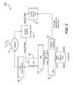
- FIG. 2is a block diagram of a remote unit 200 of one embodiment of the present invention such as the remote units 106 discussed with respect to FIG. 1 .
- Remote unit 200includes a serial radio frequency (SeRF) module 220 , a digital to analog radio frequency transceiver (DART) module 208 , a remote DART interface board (RDI) 224 , a linear power amplifier 210 , antenna 212 , a duplexer 211 , a low noise amplifier 214 and a locator receiver (LR) 216 .
- SeRF modules and DART modules and locator receivers described hereinare realized using FPGAs, ASICs, digital signal processing (DSP) boards, or similar devices.
- DART module 208provides bi-directional conversion between analog RF signals and digital sampled RF for the downlink and uplink transport signals transmitted between host unit 102 and remote units 106 .
- DART module 208receives an incoming analog RF signal from subscriber unit 108 and samples the analog RF signal to generate a digital data signal for use by SeRF module 220 .
- Antenna 212receives the wireless RF signal from subscriber 108 which passes the RF signal to DART module 208 via low noise amplifier 214 .
- DART module 208receives digital sampled RF data from SeRF module 220 , up converts the sampled RF data to a broadcast frequency, and converts the digital RF samples to analog RF for wireless transmission. After a signal is converted to an analog RF signal by DART module 208 , the analog RF signal is sent to linear power amplifier 210 for broadcast via antenna 212 . Linear power amplifier 210 amplifies the RF signal received from DART module 208 for output through duplexer 211 to antenna 212 . Duplexer 211 provides duplexing of the signal which is necessary to connect transmit and receive signals to a common antenna 212 . In one embodiment, low noise amplifier 214 is integrated into duplexer 211 .
- DART modules in a remote unitare specific for a particular frequency band.
- a single DART moduleoperates over a defined band regardless of the modulation technology being used.
- frequency band adjustments in a remote unitcan be made by replacing a DART module covering one frequency band with a DART module covering a different frequency band.
- DART module 208is designed to transmit 850 MHz cellular transmissions.
- DART module 208transmits 1900 MHz PCS signals.
- Some of the other options for DART modules 208include Nextel 800 band, Nextel 900 band, PCS full band, PCS half band, BRS, WiMax, Long Term Evolution (LTE), and the European GSM 900 , GSM 1800 , and UMTS 2100 .
- remote unit 102is configurable to any of the above frequency bands and technologies as well as any new technologies or frequency bands that are developed. Also, a single remote unit may be configured to operate over multiple bands by possessing multiple DART modules. The present discussion applies to such multiple band remote units, even though the present examples focuses on a the operation of a single DART module for simplicity.
- SeRF module 220is coupled to RDI 224 .
- RDI 224has a plurality of connectors each of which is configured to receive a pluggable DART module 208 and connect DART module 208 to SeRF module 220 .
- RDI 204is a common interface that is configured to allow communication between SeRF module 220 and different varieties of DART modules 208 .
- RDI 204is a passive host backplane to which SeRF module 220 also connects.
- RDI 204is integrated with SeRF module 220 .
- RDI 204provides separate connection interfaces allowing each DART module to communicate RF data samples with SeRF module 220 .
- FIG. 2illustrates a single SeRF module connected to a single RDI, embodiments of the present invention are not limited to such.
- a SeRF modulemay connect to multiple RDIs, each of which can connect to multiple DARTS.
- a SeRF modulecan connect to up to 3 RDIs, each of which can connect to up to 2 DARTs.
- SeRF module 220provides bidirectional conversion between a serial stream of RF, IF or baseband data samples (a SeRF stream) and a high speed optical serial data stream.
- SeRF module 220receives an incoming SeRF stream from DART modules 208 and sends a serial optical data stream over communication links 130 to host unit 102 .
- SeRF module 220receives an optical serial data stream from host unit 102 and provides a SeRF stream to DART modules 208 .
- Remote unit 200further includes a location receiver (LR) 216 for generating subscriber unit ranging data used in determining the location of a subscriber unit transmitting to remote unit 200 .
- LR 216receives an analog signal feed of the RF signals received at remote unit 200 via antenna 212 .
- low noise amplifier 214includes a secondary RF tap from which LR 216 receives the analog signal feed of the RF signals.
- LR 216is also coupled to SeRF module 220 via an interface 222 that provides bidirectional access to the Ethernet pipe between remote unit 200 and the host unit 102 .
- interface 222is a receptacle for a standard 8 Position 8 Contact (8P8C) modular plug and category 5/5e cable.
- LR 216evaluates the RF signals received at antenna 212 , looking for a signal from a particular subscriber unit, such as an individual's cellular phone for example. For example, in one embodiment, LR 216 evaluates the RF signal of a particular communication channel to make a timing measurement for a particular subscriber unit. When LR 216 finds the signal it is looking for, LR 216 generates a message indicating the time at which the signal was received at that remote unit. This message is referred to herein as subscriber unit ranging data. LR 216 formats the subscriber unit ranging data for transmission over an internet protocol (IP) network.
- IPinternet protocol
- LR 216then outputs the subscriber unit ranging data to the SeRF module 220 which in turn routes the subscriber unit ranging data over the Ethernet pipe for transport to a subscriber locator center such as SLC 140 .
- the digital distributed antenna system as described abovethus includes a first partition of bandwidth for transporting digitized radio frequency (RF) signals and a second partition of bandwidth implementing an Ethernet pipe for transporting the subscriber unit ranging data as IP formatted data.
- LR 216comprises a “Location Measurement Unit”, or “LMU”, device produced by TruePosition, Inc. and the subscriber locator center 140 comprises a Gateway Mobile Location Center produced by TruePosition, Inc.
- FIG. 2each illustrates a single DART module coupled to a SeRF module
- a single remote unit housingmay operate over multiple bands and thus include multiple DART modules.
- the systems illustrated in FIGS. 2 , 4 A and 4 Bwould simply be replicated once for each band.
- a SeRF modulealso allows multiple DART modules to operate in parallel to communicate high speed optical serial data streams over a communication link with the host unit.
- a SeRF moduleactively multiplexes the signals from multiple DART modules (each DART module processing a different RF band) such that they are sent simultaneously over a single transport communication link.
- a SeRF modulepresents a clock signal to each DART module to which it is coupled to ensure synchronization.
- FIG. 3is a flow chart illustrating a method of one embodiment of the present invention.
- the methodbegins at 310 with receiving a request for location services when a subscriber unit, such as a mobile phone, requests location services from within a digital DAS.
- the request for location servicescould comprise an emergency 911 call for help.
- the request for location serviceswould aid one or more other applications running on the mobile phone, such as, but not limited to, an application for finding nearby businesses.
- the location services requestis received as a wireless analog RF transmission by at least one remote unit antenna of a distributed antenna system having a digital transport. That is, the downlink and uplink transport signals transmitted between the DAS host unit and the remote units are generated by digitizing the downlink and uplink RF signals, respectively.
- the methodproceeds to 315 where the location services request is routed using standard call services to a subscriber locator center.
- the methodproceeds to 320 where the subscriber locator center instructs LRs located at remote units within a geographical area to listen for a signal from the requesting mobile phone.
- the instructions to the LRsare routed to the LRs through an Ethernet pipe provided within the digital transport of the DAS.
- the methodproceeds to 330 where the LRs listen for the signal from the requesting mobile phone. For example, in one embodiment, the LR scans the RF signal to identify an emergency 911 call from a subscriber unit.
- the LRsWhen the LRs receive the signal (determined at 340 ), they record the time the signal was received ( 350 ) to generate subscriber unit ranging data and send subscriber unit ranging data back to the subscriber locator center ( 360 ) by transmitting an IP formatted message over the Ethernet pipe provided within the digital transport of the DAS.
- the subscriber locator centerreceives subscriber unit ranging data from a sufficient number of LRs (typically three or more), the subscriber locator center determines the location of the mobile phone based on signal reception time data provided in the subscriber unit ranging data.
- the subscriber locator centerapplies multilateration algorithms which compute the time difference of arrival (TDOA) of signals received by LRs at multiple remote units in order to determine a position estimate of the mobile phone. The position estimate may then be communicated to emergency authorities, or back to the mobile phone.
- TDOAtime difference of arrival
- FIG. 4Ais an alternate embodiment of a remote unit 400 of one embodiment of the present invention such as the remote units 106 discussed with respect to FIG. 1 .
- Remote unit 400includes a serial radio frequency (SeRF) module 420 , a digital to analog radio frequency transceiver (DART) module 408 , a RDI 424 , a linear power amplifier 410 , a duplexer 411 , antenna 412 , a low noise amplifier 414 , each of which operate as discussed above with respect to FIG. 2 .
- serial radio frequency (SeRF) module 420includes a serial radio frequency (SeRF) module 420 , a digital to analog radio frequency transceiver (DART) module 408 , a RDI 424 , a linear power amplifier 410 , a duplexer 411 , antenna 412 , a low noise amplifier 414 , each of which operate as discussed above with respect to FIG. 2 .
- low noise amplifier 414is integrated into duplexer 411
- Remote unit 400further includes a location receiver (LR) 416 for generating subscriber unit ranging data used in determining the location of a subscriber unit transmitting to remote unit 400 .
- SeRF module 420is coupled to a RDI 424 .
- RDI 424has a plurality of connectors each of which is configured to receive a pluggable DART module 408 and connect DART module 408 to SeRF module 420 as described above in FIG. 2 .
- RDI 404further includes at least one connector to receive LR 416 .
- LR 416has the same form factor interface for plugging into RDI 404 as DART module 408 .
- LR 416receives baseband data from SeRF module 420 . That is, SeRF module 420 receives the digital RF samples generated by DART module 408 which have been down converted to a sampled baseband digital signal. That is, the baseband digital signal provides digital samples of a DC centered baseband RF signal for the spectrum digitized by DART module 480 . SeRF module 420 includes a loop-back feature 430 to provide the sampled baseband digital signal to LR 416 .
- SeRF module 420can loop-back sampled baseband digital signal from any number of DART modules coupled to SeRF module 420 .
- multiple DART modulescould be present when a remote unit operates with RF signals transmitted and received on multiple bands.
- LR 416evaluates the sampled baseband digital signal looking for a signal from a particular subscriber unit, such as an individual's cellular phone for example. For example, in one embodiment, LR 416 scans the sampled baseband digital signal to identify an emergency 911 call from a subscriber unit. When LR 416 finds the signal it is looking for, LR 416 generates subscriber unit ranging data indicating the time at which the signal was received at that remote unit. LR 416 formats the subscriber unit ranging data for transmission over an internet protocol (IP) network and outputs the subscriber unit ranging data to the SeRF module 420 which in turn routes the subscriber unit ranging data over the Ethernet pipe for transport to a subscriber locator center such as SLC 140 .
- IPinternet protocol
- DART 480generates a fully down converted digital representation of the RF band of interest to LR 416 .
- One advantage of having the LR evaluate a sampled baseband digital signal rather than an analog RF signalis that the LR does not need to be designed to perform the digital sampling and down converting of an analog RF signal itself, which can result in less expensive design and manufacturing costs for an LR.
- LR 416is also coupled to SeRF module 420 via an interface 422 that provides bidirectional access to the Ethernet pipe between remote unit 400 and the host unit.
- interface 422is a receptacle for a standard 8 Position 8 Contact (8P8C) modular plug and category 5/5e cable.
- P8C8 Position 8 Contact
- FIG. 4Bbidirectional access to the Ethernet pipe between remote unit 400 and the host unit is directly accessible by LR 416 over RDI 424 shown generally at 435 .
- SeRF module 420would packet the subscriber unit ranging data using a MAC address, thus assigning a virtual network port associated with LR 416 .
- SeRF module 420receives the digital RF samples generated by DART module 408 , which have been converted into baseband digital samples.
- LR 416evaluates the baseband digital samples looking for a signal from a particular subscriber unit as described above.
- DART modulesmay function to optionally convert the digital RF samples into intermediate frequency (IF) samples instead of, or in addition to, baseband digital samples.
- IFintermediate frequency
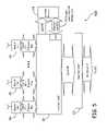
- FIG. 5is a block diagram illustrating a host unit (shown generally at 500 ) of one embodiment of the present invention such as the host unit 102 discussed with respect to FIG. 1 .
- Multiple remote units 506are coupled to host unit 500 , as described with respect to FIG. 1 , to form a digital DAS.
- Host unit 500includes a host unit digital to analog radio frequency transceiver (DART) module 508 and a host unit serial radio frequency (SeRF) module 520 .
- DARTdigital to analog radio frequency transceiver
- SeRFhost unit serial radio frequency
- SeRF module 520provides bi-directional conversion between a serial stream of RF data samples (a SeRF stream) and the multiple high speed optical serial data streams to and from the remote units 506 .
- Each serial optical data streamincludes a digital transport for communicating downlink and uplink transport RF signals as well as an Ethernet pipe between each remote unit 506 and host unit 500 .
- SeRF module 520receives incoming serial optical data streams from a plurality of remote units and converts each into a serial stream of digitized baseband RF data samples, which are summed into a broadband stream of RF data samples.
- DART module 508provides a bidirectional interface between SeRF module 520 and one or more base stations, such as BTS 110 .
- a separate DART module 508is provided for each frequency band.
- Host unit 500also maintains an Ethernet pipe with at least one base station which provides access to at least one Internet gateway.
- Location Receiver (LR) 530is coupled to an Ethernet port interface 524 of SeRF module 520 via an Ethernet link 525 .
- Ethernet link 525may include a local area network (LAN), wide area network (WAN) having at least one network switch for routing data between interface 524 and LR 530 .
- LR 530is further coupled to SeRF module 520 to receive digital RF data samples.
- SeRF module 520provides LR 530 with access to the individual serial streams of RF data from remote units 506 , before the data is summed into the broadband stream of RF data samples.
- LR 530selects one serial stream of RF data received from one of the remote units, and listens for a signal from a particular subscriber unit, such as an individual's cellular phone for example. LR 530 can observe data from any of the time slots of any of the bands operating through that remote. For example, in one embodiment, LR 530 evaluates the RF signal of a particular communication channel to make a timing measurement for a particular subscriber unit. When LR 530 finds the signal it is looking for, LR 530 generates subscriber unit ranging data indicating the time at which the signal was received at that remote unit.
- LR 530compensates by determining the time the digitized RF data samples are received at host unit 500 and subtracting a propagation delay time associate with that particular remote unit 506 . Propagation delay times for each remote unit 506 may be either known a priori by LR 530 or periodically measured. The subscriber unit ranging data generated by LR 530 thus represents the time the RF signal was received at the remote unit.
- LR 530formats the subscriber unit ranging data for transmission over an internet protocol (IP) network and outputs the subscriber unit ranging data to the SeRF module 520 which in turn routes the subscriber unit ranging data over the Ethernet pipe for transport to a subscriber locator center such as SLC 140 .
- IPinternet protocol
- LR 530listens for a signal from a particular subscriber unit simultaneously on multiple serial streams of RF data from multiple remote units 506 . In that case the subscriber unit ranging data generated by LR 530 is adjusted for propagation delay based on the which remote unit 506 received the corresponding analog RF signal.
- LR 530comprises several individual location receivers each dedicated to observing signals from a specified remote unit.
- LR 530is remotely configurable, for example from a management interface at a subscriber locator center, to look for specific samples within a specific RF band received at a specific remote unit antenna.
- Computer readable mediainclude devices such as any physical form of computer memory, including but not limited to punch cards, magnetic disk or tape, any optical data storage system, flash read only memory (ROM), non-volatile ROM, programmable ROM (PROM), erasable-programmable ROM (E-PROM), random access memory (RAM), or any other form of permanent, semi-permanent, or temporary memory storage system or device.
- Program instructionsinclude, but are not limited to computer-executable instructions executed by computer system processors and hardware description languages such as Very High Speed Integrated Circuit (VHSIC) Hardware Description Language (VHDL).
- VHSICVery High Speed Integrated Circuit
- VHDLHardware Description Language
Landscapes
- Engineering & Computer Science (AREA)
- Computer Networks & Wireless Communication (AREA)
- Signal Processing (AREA)
- Physics & Mathematics (AREA)
- Remote Sensing (AREA)
- Radar, Positioning & Navigation (AREA)
- General Physics & Mathematics (AREA)
- Business, Economics & Management (AREA)
- Public Health (AREA)
- Environmental & Geological Engineering (AREA)
- Emergency Management (AREA)
- Health & Medical Sciences (AREA)
- Mobile Radio Communication Systems (AREA)
- Telephonic Communication Services (AREA)
Abstract
Description
Claims (19)
Priority Applications (10)
| Application Number | Priority Date | Filing Date | Title |
|---|---|---|---|
| US12/555,923US8346278B2 (en) | 2009-01-13 | 2009-09-09 | Systems and methods for mobile phone location with digital distributed antenna systems |
| CN201080004462.0ACN102282897B (en) | 2009-01-13 | 2010-01-11 | Systems and methods for mobile phone location with digital distributed antenna systems |
| JP2011546287AJP2012515503A (en) | 2009-01-13 | 2010-01-11 | System and method for mobile phone location with digital distributed antenna system |
| EP10731977.4AEP2387861B1 (en) | 2009-01-13 | 2010-01-11 | Systems and methods for mobile phone location with digital distributed antenna systems |
| EP20178954.2AEP3726897A1 (en) | 2009-01-13 | 2010-01-11 | Systems and methods for mobile phone location with digital distributed antenna systems |
| AU2010204891AAU2010204891B2 (en) | 2009-01-13 | 2010-01-11 | Systems and methods for mobile phone location with digital distributed antenna systems |
| PCT/US2010/020588WO2010083115A2 (en) | 2009-01-13 | 2010-01-11 | Systems and methods for mobile phone location with digital distributed antenna systems |
| KR1020117016254AKR20110104957A (en) | 2009-01-13 | 2010-01-11 | System and Method for Mobile Phone Positioning Using Digital Distributed Antenna System |
| US13/529,607US8958410B2 (en) | 2009-01-13 | 2012-06-21 | Systems and methods for IP communication over a distributed antenna system transport |
| US13/681,535US8526970B2 (en) | 2009-01-13 | 2012-11-20 | Systems and methods for mobile phone location with digital distributed antenna systems |
Applications Claiming Priority (2)
| Application Number | Priority Date | Filing Date | Title |
|---|---|---|---|
| US14425709P | 2009-01-13 | 2009-01-13 | |
| US12/555,923US8346278B2 (en) | 2009-01-13 | 2009-09-09 | Systems and methods for mobile phone location with digital distributed antenna systems |
Related Child Applications (1)
| Application Number | Title | Priority Date | Filing Date |
|---|---|---|---|
| US13/681,535ContinuationUS8526970B2 (en) | 2009-01-13 | 2012-11-20 | Systems and methods for mobile phone location with digital distributed antenna systems |
Publications (2)
| Publication Number | Publication Date |
|---|---|
| US20100178936A1 US20100178936A1 (en) | 2010-07-15 |
| US8346278B2true US8346278B2 (en) | 2013-01-01 |
Family
ID=42319439
Family Applications (2)
| Application Number | Title | Priority Date | Filing Date |
|---|---|---|---|
| US12/555,923Expired - Fee RelatedUS8346278B2 (en) | 2009-01-13 | 2009-09-09 | Systems and methods for mobile phone location with digital distributed antenna systems |
| US13/681,535Expired - Fee RelatedUS8526970B2 (en) | 2009-01-13 | 2012-11-20 | Systems and methods for mobile phone location with digital distributed antenna systems |
Family Applications After (1)
| Application Number | Title | Priority Date | Filing Date |
|---|---|---|---|
| US13/681,535Expired - Fee RelatedUS8526970B2 (en) | 2009-01-13 | 2012-11-20 | Systems and methods for mobile phone location with digital distributed antenna systems |
Country Status (7)
| Country | Link |
|---|---|
| US (2) | US8346278B2 (en) |
| EP (2) | EP2387861B1 (en) |
| JP (1) | JP2012515503A (en) |
| KR (1) | KR20110104957A (en) |
| CN (1) | CN102282897B (en) |
| AU (1) | AU2010204891B2 (en) |
| WO (1) | WO2010083115A2 (en) |
Cited By (51)
| Publication number | Priority date | Publication date | Assignee | Title |
|---|---|---|---|---|
| US9037143B2 (en) | 2010-08-16 | 2015-05-19 | Corning Optical Communications LLC | Remote antenna clusters and related systems, components, and methods supporting digital data signal propagation between remote antenna units |
| US9042732B2 (en) | 2010-05-02 | 2015-05-26 | Corning Optical Communications LLC | Providing digital data services in optical fiber-based distributed radio frequency (RF) communication systems, and related components and methods |
| US9112611B2 (en) | 2009-02-03 | 2015-08-18 | Corning Optical Communications LLC | Optical fiber-based distributed antenna systems, components, and related methods for calibration thereof |
| US9178635B2 (en) | 2014-01-03 | 2015-11-03 | Corning Optical Communications Wireless Ltd | Separation of communication signal sub-bands in distributed antenna systems (DASs) to reduce interference |
| US9184843B2 (en) | 2011-04-29 | 2015-11-10 | Corning Optical Communications LLC | Determining propagation delay of communications in distributed antenna systems, and related components, systems, and methods |
| US9219879B2 (en) | 2009-11-13 | 2015-12-22 | Corning Optical Communications LLC | Radio-over-fiber (ROF) system for protocol-independent wired and/or wireless communication |
| US9240835B2 (en) | 2011-04-29 | 2016-01-19 | Corning Optical Communications LLC | Systems, methods, and devices for increasing radio frequency (RF) power in distributed antenna systems |
| US9247543B2 (en) | 2013-07-23 | 2016-01-26 | Corning Optical Communications Wireless Ltd | Monitoring non-supported wireless spectrum within coverage areas of distributed antenna systems (DASs) |
| US20160029339A1 (en)* | 2010-08-09 | 2016-01-28 | Corning Optical Communications LLC | Apparatuses, systems, and methods for determining location of a mobile device(s) in a distributed antenna system(s) |
| US9253003B1 (en) | 2014-09-25 | 2016-02-02 | Corning Optical Communications Wireless Ltd | Frequency shifting a communications signal(S) in a multi-frequency distributed antenna system (DAS) to avoid or reduce frequency interference |
| US20160056865A1 (en)* | 2014-08-22 | 2016-02-25 | Adc Telecommunications, Inc. | Distributed antenna system with adaptive allocation between digitized rf data and ip formatted data |
| US9307506B1 (en)* | 2014-09-09 | 2016-04-05 | Sprint Communications Company L.P. | Implementation of a fiber distributed antenna system network while maintaining synchronization |
| US9319138B2 (en) | 2010-02-15 | 2016-04-19 | Corning Optical Communications LLC | Dynamic cell bonding (DCB) for radio-over-fiber (RoF)-based networks and communication systems and related methods |
| US9325429B2 (en) | 2011-02-21 | 2016-04-26 | Corning Optical Communications LLC | Providing digital data services as electrical signals and radio-frequency (RF) communications over optical fiber in distributed communications systems, and related components and methods |
| US9338823B2 (en) | 2012-03-23 | 2016-05-10 | Corning Optical Communications Wireless Ltd | Radio-frequency integrated circuit (RFIC) chip(s) for providing distributed antenna system functionalities, and related components, systems, and methods |
| US9357551B2 (en) | 2014-05-30 | 2016-05-31 | Corning Optical Communications Wireless Ltd | Systems and methods for simultaneous sampling of serial digital data streams from multiple analog-to-digital converters (ADCS), including in distributed antenna systems |
| US9385810B2 (en) | 2013-09-30 | 2016-07-05 | Corning Optical Communications Wireless Ltd | Connection mapping in distributed communication systems |
| US9420542B2 (en) | 2014-09-25 | 2016-08-16 | Corning Optical Communications Wireless Ltd | System-wide uplink band gain control in a distributed antenna system (DAS), based on per band gain control of remote uplink paths in remote units |
| US9455784B2 (en) | 2012-10-31 | 2016-09-27 | Corning Optical Communications Wireless Ltd | Deployable wireless infrastructures and methods of deploying wireless infrastructures |
| US9525488B2 (en) | 2010-05-02 | 2016-12-20 | Corning Optical Communications LLC | Digital data services and/or power distribution in optical fiber-based distributed communications systems providing digital data and radio frequency (RF) communications services, and related components and methods |
| US9602210B2 (en) | 2014-09-24 | 2017-03-21 | Corning Optical Communications Wireless Ltd | Flexible head-end chassis supporting automatic identification and interconnection of radio interface modules and optical interface modules in an optical fiber-based distributed antenna system (DAS) |
| US9621293B2 (en) | 2012-08-07 | 2017-04-11 | Corning Optical Communications Wireless Ltd | Distribution of time-division multiplexed (TDM) management services in a distributed antenna system, and related components, systems, and methods |
| US20170111957A1 (en)* | 2015-05-22 | 2017-04-20 | Solid, Inc. | Signal processing device for distributed antenna system |
| US9647758B2 (en) | 2012-11-30 | 2017-05-09 | Corning Optical Communications Wireless Ltd | Cabling connectivity monitoring and verification |
| US9661781B2 (en) | 2013-07-31 | 2017-05-23 | Corning Optical Communications Wireless Ltd | Remote units for distributed communication systems and related installation methods and apparatuses |
| US9673904B2 (en) | 2009-02-03 | 2017-06-06 | Corning Optical Communications LLC | Optical fiber-based distributed antenna systems, components, and related methods for calibration thereof |
| US9681313B2 (en) | 2015-04-15 | 2017-06-13 | Corning Optical Communications Wireless Ltd | Optimizing remote antenna unit performance using an alternative data channel |
| US9715157B2 (en) | 2013-06-12 | 2017-07-25 | Corning Optical Communications Wireless Ltd | Voltage controlled optical directional coupler |
| US9730228B2 (en) | 2014-08-29 | 2017-08-08 | Corning Optical Communications Wireless Ltd | Individualized gain control of remote uplink band paths in a remote unit in a distributed antenna system (DAS), based on combined uplink power level in the remote unit |
| US9775123B2 (en) | 2014-03-28 | 2017-09-26 | Corning Optical Communications Wireless Ltd. | Individualized gain control of uplink paths in remote units in a distributed antenna system (DAS) based on individual remote unit contribution to combined uplink power |
| US9807700B2 (en) | 2015-02-19 | 2017-10-31 | Corning Optical Communications Wireless Ltd | Offsetting unwanted downlink interference signals in an uplink path in a distributed antenna system (DAS) |
| US9813229B2 (en) | 2007-10-22 | 2017-11-07 | Corning Optical Communications Wireless Ltd | Communication system using low bandwidth wires |
| US9823334B2 (en) | 2014-10-20 | 2017-11-21 | Commscope Technologies Llc | Time of arrival information passing in a distributed antenna system |
| US9948349B2 (en) | 2015-07-17 | 2018-04-17 | Corning Optical Communications Wireless Ltd | IOT automation and data collection system |
| US9967032B2 (en) | 2010-03-31 | 2018-05-08 | Corning Optical Communications LLC | Localization services in optical fiber-based distributed communications components and systems, and related methods |
| US9974074B2 (en) | 2013-06-12 | 2018-05-15 | Corning Optical Communications Wireless Ltd | Time-division duplexing (TDD) in distributed communications systems, including distributed antenna systems (DASs) |
| US10070258B2 (en) | 2009-07-24 | 2018-09-04 | Corning Optical Communications LLC | Location tracking using fiber optic array cables and related systems and methods |
| US10096909B2 (en) | 2014-11-03 | 2018-10-09 | Corning Optical Communications Wireless Ltd. | Multi-band monopole planar antennas configured to facilitate improved radio frequency (RF) isolation in multiple-input multiple-output (MIMO) antenna arrangement |
| US10110308B2 (en) | 2014-12-18 | 2018-10-23 | Corning Optical Communications Wireless Ltd | Digital interface modules (DIMs) for flexibly distributing digital and/or analog communications signals in wide-area analog distributed antenna systems (DASs) |
| US10128951B2 (en) | 2009-02-03 | 2018-11-13 | Corning Optical Communications LLC | Optical fiber-based distributed antenna systems, components, and related methods for monitoring and configuring thereof |
| US10136200B2 (en) | 2012-04-25 | 2018-11-20 | Corning Optical Communications LLC | Distributed antenna system architectures |
| US10135533B2 (en) | 2014-11-13 | 2018-11-20 | Corning Optical Communications Wireless Ltd | Analog distributed antenna systems (DASS) supporting distribution of digital communications signals interfaced from a digital signal source and analog radio frequency (RF) communications signals |
| US10164689B2 (en) | 2014-08-22 | 2018-12-25 | Commscope Technologies Llc | Distributed antenna system to transport first cellular RF band concurrently with Ethernet or second cellular RF band |
| US10187151B2 (en) | 2014-12-18 | 2019-01-22 | Corning Optical Communications Wireless Ltd | Digital-analog interface modules (DAIMs) for flexibly distributing digital and/or analog communications signals in wide-area analog distributed antenna systems (DASs) |
| US10236924B2 (en) | 2016-03-31 | 2019-03-19 | Corning Optical Communications Wireless Ltd | Reducing out-of-channel noise in a wireless distribution system (WDS) |
| USRE47466E1 (en)* | 2009-01-13 | 2019-06-25 | Commscope Technologies Llc | Systems and methods for IP communication over a distributed antenna system transport |
| US10348420B2 (en)* | 2016-06-28 | 2019-07-09 | Marek E. Antkowiak | Antenna status remote monitoring system |
| US10560214B2 (en) | 2015-09-28 | 2020-02-11 | Corning Optical Communications LLC | Downlink and uplink communication path switching in a time-division duplex (TDD) distributed antenna system (DAS) |
| US10659163B2 (en) | 2014-09-25 | 2020-05-19 | Corning Optical Communications LLC | Supporting analog remote antenna units (RAUs) in digital distributed antenna systems (DASs) using analog RAU digital adaptors |
| US20210100066A1 (en)* | 2019-09-26 | 2021-04-01 | Commscope Technologies Llc | Passive backplane architecture for master unit of distributed antenna system |
| US11178609B2 (en) | 2010-10-13 | 2021-11-16 | Corning Optical Communications LLC | Power management for remote antenna units in distributed antenna systems |
Families Citing this family (76)
| Publication number | Priority date | Publication date | Assignee | Title |
|---|---|---|---|---|
| US8811917B2 (en) | 2002-05-01 | 2014-08-19 | Dali Systems Co. Ltd. | Digital hybrid mode power amplifier system |
| US8380143B2 (en) | 2002-05-01 | 2013-02-19 | Dali Systems Co. Ltd | Power amplifier time-delay invariant predistortion methods and apparatus |
| US9288623B2 (en) | 2005-12-15 | 2016-03-15 | Invisitrack, Inc. | Multi-path mitigation in rangefinding and tracking objects using reduced attenuation RF technology |
| US10834531B2 (en) | 2005-12-15 | 2020-11-10 | Polte Corporation | Multi-path mitigation in rangefinding and tracking objects using reduced attenuation RF technology |
| US9813867B2 (en) | 2005-12-15 | 2017-11-07 | Polte Corporation | Angle of arrival (AOA) positioning method and system for positional finding and tracking objects using reduced attenuation RF technology |
| US9913244B2 (en) | 2005-12-15 | 2018-03-06 | Polte Corporation | Partially synchronized multilateration or trilateration method and system for positional finding using RF |
| US9699607B2 (en) | 2005-12-15 | 2017-07-04 | Polte Corporation | Multi-path mitigation in rangefinding and tracking objects using reduced attenuation RF technology |
| US9507007B2 (en)* | 2005-12-15 | 2016-11-29 | Polte Corporation | Multi-path mitigation in rangefinding and tracking objects using reduced attenuation RF technology |
| US10281557B2 (en) | 2005-12-15 | 2019-05-07 | Polte Corporation | Partially synchronized multilateration/trilateration method and system for positional finding using RF |
| US10091616B2 (en) | 2005-12-15 | 2018-10-02 | Polte Corporation | Angle of arrival (AOA) positioning method and system for positional finding and tracking objects using reduced attenuation RF technology |
| CN102017553B (en) | 2006-12-26 | 2014-10-15 | 大力系统有限公司 | Method and system for baseband predistortion linearization in a multi-channel broadband communication system |
| US20100054746A1 (en) | 2007-07-24 | 2010-03-04 | Eric Raymond Logan | Multi-port accumulator for radio-over-fiber (RoF) wireless picocellular systems |
| US8175459B2 (en) | 2007-10-12 | 2012-05-08 | Corning Cable Systems Llc | Hybrid wireless/wired RoF transponder and hybrid RoF communication system using same |
| US8644844B2 (en) | 2007-12-20 | 2014-02-04 | Corning Mobileaccess Ltd. | Extending outdoor location based services and applications into enclosed areas |
| US8346278B2 (en) | 2009-01-13 | 2013-01-01 | Adc Telecommunications, Inc. | Systems and methods for mobile phone location with digital distributed antenna systems |
| US8213401B2 (en) | 2009-01-13 | 2012-07-03 | Adc Telecommunications, Inc. | Systems and methods for IP communication over a distributed antenna system transport |
| US8346091B2 (en)* | 2009-04-29 | 2013-01-01 | Andrew Llc | Distributed antenna system for wireless network systems |
| US8472579B2 (en)* | 2010-07-28 | 2013-06-25 | Adc Telecommunications, Inc. | Distributed digital reference clock |
| KR101835254B1 (en) | 2010-08-17 | 2018-03-06 | 달리 시스템즈 씨오. 엘티디. | Neutral host architecture for a distributed antenna system |
| CN103597807B (en) | 2010-09-14 | 2015-09-30 | 大理系统有限公司 | Remotely reconfigurable distributed antenna system and method |
| KR101472100B1 (en)* | 2010-12-22 | 2014-12-11 | 주식회사 케이티 | Base station apparatus and data processing method in wireless communication system |
| US8630319B2 (en) | 2011-04-05 | 2014-01-14 | Cisco Technology, Inc. | Multi-receiver combining for distributed antenna systems with code division multiple access radio frequency uplink sources |
| AU2012267611B2 (en) | 2011-06-09 | 2016-11-17 | Commscope Technologies Llc | Distributed antenna system using power-over-ethernet |
| KR101971584B1 (en)* | 2011-06-29 | 2019-04-23 | 콤스코프 커넥티비티 엘엘씨 | Evolved distributed antenna system |
| CN103733664B (en) | 2011-07-11 | 2017-10-24 | 康普技术有限责任公司 | Method and apparatus for managing a distributed antenna system |
| US11125850B2 (en) | 2011-08-03 | 2021-09-21 | Polte Corporation | Systems and methods for determining a timing offset of emitter antennas in a wireless network |
| US11835639B2 (en) | 2011-08-03 | 2023-12-05 | Qualcomm Technologies, Inc. | Partially synchronized multilateration or trilateration method and system for positional finding using RF |
| AU2012302074B2 (en)* | 2011-08-29 | 2017-02-16 | Commscope Technologies Llc | Configuring a distributed antenna system |
| WO2013040589A1 (en) | 2011-09-15 | 2013-03-21 | Andrew Wireless Systems Gmbh | Configuration sub-system for telecommunication systems |
| EP2661828B1 (en) | 2011-09-16 | 2016-03-23 | Andrew Wireless Systems GmbH | Integrated intermodulation detection sub-system for telecommunications systems |
| US11564110B2 (en) | 2011-11-07 | 2023-01-24 | Dali Wireless, Inc. | Soft hand-off and routing data in a virtualized distributed antenna system |
| EP3627718B1 (en)* | 2012-02-14 | 2022-05-11 | ADC Telecommunications, Inc. | Timing adjustments for small cell distributed antenna systems |
| US8909249B2 (en)* | 2012-02-29 | 2014-12-09 | Keysight Technologies, Inc. | Passive uplink time difference of arrival positioning and tracking system |
| US9781553B2 (en) | 2012-04-24 | 2017-10-03 | Corning Optical Communications LLC | Location based services in a distributed communication system, and related components and methods |
| WO2013181247A1 (en) | 2012-05-29 | 2013-12-05 | Corning Cable Systems Llc | Ultrasound-based localization of client devices with inertial navigation supplement in distributed communication systems and related devices and methods |
| EP2873164A4 (en) | 2012-07-11 | 2016-03-02 | Adc Telecommunications Inc | Distributed antenna system with managed connectivity |
| US9107086B2 (en)* | 2012-07-20 | 2015-08-11 | Adc Telecommunications, Inc. | Integration panel |
| US10440512B2 (en) | 2012-08-03 | 2019-10-08 | Polte Corporation | Angle of arrival (AOA) positioning method and system for positional finding and tracking objects using reduced attenuation RF technology |
| US10863313B2 (en) | 2014-08-01 | 2020-12-08 | Polte Corporation | Network architecture and methods for location services |
| US10845453B2 (en) | 2012-08-03 | 2020-11-24 | Polte Corporation | Network architecture and methods for location services |
| DE202013012858U1 (en) | 2012-08-09 | 2021-05-07 | Axel Wireless Ltd. | Capacity-centered digital distributed antenna system |
| US9439242B2 (en)* | 2012-08-13 | 2016-09-06 | Dali Systems Co., Ltd. | Time synchronized routing in a distributed antenna system |
| US9894623B2 (en) | 2012-09-14 | 2018-02-13 | Andrew Wireless Systems Gmbh | Uplink path integrity detection in distributed antenna systems |
| GB2505965B (en)* | 2012-09-18 | 2015-06-10 | Toshiba Res Europ Ltd | Controller for coordinating wireless transmissions between a plurality of radio units and one or more user devices |
| US9913147B2 (en) | 2012-10-05 | 2018-03-06 | Andrew Wireless Systems Gmbh | Capacity optimization sub-system for distributed antenna system |
| AU2013338583B2 (en) | 2012-10-31 | 2017-08-31 | Commscope Technologies Llc | Digital baseband transport in telecommunications distribution systems |
| US9158864B2 (en) | 2012-12-21 | 2015-10-13 | Corning Optical Communications Wireless Ltd | Systems, methods, and devices for documenting a location of installed equipment |
| WO2014124432A1 (en)* | 2013-02-11 | 2014-08-14 | Andrew Llc | Automatic configuration sub-system for distributed antenna systems |
| CA2914104C (en) | 2013-02-22 | 2022-12-13 | Adc Telecommunications, Inc. | Master reference for base station network interface sourced from distributed antenna system |
| US9955361B2 (en)* | 2013-02-26 | 2018-04-24 | Dali Systems Co., Ltd. | Method and system for WI-FI data transmission |
| US9077321B2 (en) | 2013-10-23 | 2015-07-07 | Corning Optical Communications Wireless Ltd. | Variable amplitude signal generators for generating a sinusoidal signal having limited direct current (DC) offset variation, and related devices, systems, and methods |
| US9847816B2 (en) | 2013-12-19 | 2017-12-19 | Dali Systems Co. Ltd. | Digital transport of data over distributed antenna network |
| US20170250927A1 (en) | 2013-12-23 | 2017-08-31 | Dali Systems Co. Ltd. | Virtual radio access network using software-defined network of remotes and digital multiplexing switches |
| EP3092832B1 (en)* | 2014-01-06 | 2024-08-07 | Dali Systems Co. Ltd. | Network switch for a distributed antenna network |
| US9768855B2 (en) | 2014-01-27 | 2017-09-19 | Commscope Technologies Llc | Multi-stage isolation sub-system for a remote antenna unit |
| US20150256358A1 (en)* | 2014-03-05 | 2015-09-10 | Dali Systems Co. Ltd. | Distributed radio system with remote radio heads |
| US9722703B2 (en)* | 2014-03-21 | 2017-08-01 | Commscope Technologies Llc | Digital distributed antenna systems and methods for advanced cellular communication protocols |
| US10965159B2 (en) | 2014-05-29 | 2021-03-30 | Sony Corporation | Scalable antenna system |
| US9843360B2 (en) | 2014-08-14 | 2017-12-12 | Sony Corporation | Method and system for use in configuring multiple near field antenna systems |
| US10277280B2 (en) | 2014-05-29 | 2019-04-30 | Sony Interactive Entertainment LLC | Configuration of data and power transfer in near field communications |
| US9577463B2 (en) | 2014-05-29 | 2017-02-21 | Sony Corporation | Portable device to portable device wireless power transfer methods and systems |
| AU2015274511B2 (en) | 2014-06-11 | 2019-08-15 | Outdoor Wireless Networks LLC | Bitrate efficient transport through distributed antenna systems |
| US9516461B2 (en) | 2014-07-16 | 2016-12-06 | Sony Corporation | Mesh network applied to arena events |
| US9900748B2 (en) | 2014-07-16 | 2018-02-20 | Sony Corporation | Consumer electronics (CE) device and related method for providing stadium services |
| US10127601B2 (en) | 2014-07-16 | 2018-11-13 | Sony Corporation | Mesh network applied to fixed establishment with movable items therein |
| US9361802B2 (en) | 2014-07-16 | 2016-06-07 | Sony Corporation | Vehicle ad hoc network (VANET) |
| TWI552547B (en)* | 2014-07-22 | 2016-10-01 | 廣達電腦股份有限公司 | Data transmission service switch system and method |
| CA2961696A1 (en) | 2014-09-23 | 2016-03-31 | Axell Wireless Ltd. | Automatic mapping and handling pim and other uplink interferences in digital distributed antenna systems |
| CN105830510A (en)* | 2014-09-26 | 2016-08-03 | Adc电信公司 | Systems and methods for location determination |
| EP3238352A4 (en) | 2014-12-23 | 2018-08-22 | Axell Wireless Ltd. | Harmonizing noise aggregation and noise management in distributed antenna system |
| EP3320369B1 (en)* | 2015-07-06 | 2021-12-01 | Dali Systems Co. Ltd. | Distributed antenna system network analytics |
| US20170026784A1 (en)* | 2015-07-24 | 2017-01-26 | Qualcomm Incorporated | Mapping multiple antenna systems using crowdsourcing data |
| US9648580B1 (en) | 2016-03-23 | 2017-05-09 | Corning Optical Communications Wireless Ltd | Identifying remote units in a wireless distribution system (WDS) based on assigned unique temporal delay patterns |
| IT201600131387A1 (en) | 2016-12-27 | 2018-06-27 | Teko Telecom S R L | RECONFIGURABLE REMOTE RADIO UNIT FOR ANTENNA DISTRIBUTED SYSTEMS |
| US11255945B2 (en) | 2018-03-27 | 2022-02-22 | Polte Corporation | Multi-path mitigation in tracking objects using compressed RF data |
| CN108449793B (en)* | 2018-05-17 | 2024-05-10 | 成都四相致新科技有限公司 | One-dimensional positioning base station and positioning method |
Citations (42)
| Publication number | Priority date | Publication date | Assignee | Title |
|---|---|---|---|---|
| US4183054A (en) | 1977-09-30 | 1980-01-08 | Harris Corporation | Digital, frequency-translated, plural-channel, vestigial sideband television communication system |
| US4611323A (en) | 1983-05-24 | 1986-09-09 | Ant Nachrichtentechnik Gmbh | Method for transmitting digitally coded analog signals |
| US4628501A (en) | 1983-12-29 | 1986-12-09 | The United States Of America As Represented By The Secretary Of The Army | Optical communications systems |
| US4654843A (en) | 1982-09-17 | 1987-03-31 | U.S. Philips Corporation | Signal distribution system |
| US4691292A (en) | 1983-04-13 | 1987-09-01 | Rca Corporation | System for digital multiband filtering |
| EP0391597A2 (en) | 1989-04-04 | 1990-10-10 | AT&T Corp. | Optical fiber microcellular mobile radio |
| US4999831A (en) | 1989-10-19 | 1991-03-12 | United Telecommunications, Inc. | Synchronous quantized subcarrier multiplexer for digital transport of video, voice and data |
| WO1991015927A1 (en) | 1990-04-10 | 1991-10-17 | British Telecommunications Public Limited Company | Signal distribution |
| US5193109A (en) | 1989-02-06 | 1993-03-09 | Pactel Corporation | Zoned microcell with sector scanning for cellular telephone system |
| US5243598A (en) | 1991-04-02 | 1993-09-07 | Pactel Corporation | Microcell system in digital cellular |
| US5321849A (en) | 1991-05-22 | 1994-06-14 | Southwestern Bell Technology Resources, Inc. | System for controlling signal level at both ends of a transmission link based on a detected valve |
| US5339184A (en) | 1992-06-15 | 1994-08-16 | Gte Laboratories Incorporated | Fiber optic antenna remoting for multi-sector cell sites |
| US5627879A (en) | 1992-09-17 | 1997-05-06 | Adc Telecommunications, Inc. | Cellular communications system with centralized base stations and distributed antenna units |
| US6603976B1 (en) | 1999-08-03 | 2003-08-05 | Ericsson, Inc. | Architecture for TOA positioning with LMU control functionality in BSC |
| US6704545B1 (en) | 2000-07-19 | 2004-03-09 | Adc Telecommunications, Inc. | Point-to-multipoint digital radio frequency transport |
| US20040106435A1 (en) | 2002-12-03 | 2004-06-03 | Adc Telecommunications, Inc. | Distributed digital antenna system |
| US6831901B2 (en) | 2002-05-31 | 2004-12-14 | Opencell Corporation | System and method for retransmission of data |
| US20050186937A1 (en) | 2004-02-24 | 2005-08-25 | Gerald Graham | System and method for emergency 911 location detection |
| US6963552B2 (en) | 2000-03-27 | 2005-11-08 | Adc Telecommunications, Inc. | Multi-protocol distributed wireless system architecture |
| US7039399B2 (en) | 2002-03-11 | 2006-05-02 | Adc Telecommunications, Inc. | Distribution of wireless telephony and data signals in a substantially closed environment |
| US20060172775A1 (en) | 2005-02-01 | 2006-08-03 | Adc Telecommunications, Inc. | Scalable distributed radio network |
| US7103377B2 (en) | 2002-12-03 | 2006-09-05 | Adc Telecommunications, Inc. | Small signal threshold and proportional gain distributed digital communications |
| US20070008939A1 (en) | 2005-06-10 | 2007-01-11 | Adc Telecommunications, Inc. | Providing wireless coverage into substantially closed environments |
| US7171244B2 (en) | 2002-12-03 | 2007-01-30 | Adc Telecommunications, Inc. | Communication system and method with gain control for signals from distributed antennas |
| US7224170B2 (en) | 2004-12-27 | 2007-05-29 | P. G. Electronics | Fault monitoring in a distributed antenna system |
| US7286507B1 (en) | 2005-10-04 | 2007-10-23 | Sprint Spectrum L.P. | Method and system for dynamically routing between a radio access network and distributed antenna system remote antenna units |
| US20080014948A1 (en) | 2006-07-14 | 2008-01-17 | Lgc Wireless, Inc. | System for and method of for providing dedicated capacity in a cellular network |
| US7336961B1 (en) | 2004-06-04 | 2008-02-26 | Sprint Spectrum L.P. | Method and system for determining location of a mobile station within a distributed antenna system |
| US20080058018A1 (en) | 2006-08-29 | 2008-03-06 | Lgc Wireless, Inc. | Distributed antenna communications system and methods of implementing thereof |
| US20080151846A1 (en) | 2006-12-22 | 2008-06-26 | Stefan Scheinert | System for and method of providing remote coverage area for wireless communications |
| US20080181171A1 (en) | 2007-01-25 | 2008-07-31 | Adc Telecommunications, Inc. | Distributed remote base station system |
| US20080181282A1 (en) | 2007-01-25 | 2008-07-31 | Adc Telecommunications, Inc. | Modular wireless communications platform |
| US20080232328A1 (en) | 2007-03-23 | 2008-09-25 | Stefan Scheinert | Localization of a mobile device in distributed antenna communications system |
| US20080267142A1 (en) | 2004-06-18 | 2008-10-30 | Stellaris Ltd. | Distributed Antenna Wlan Access-Point System and Method |
| US20090005096A1 (en) | 2007-06-26 | 2009-01-01 | Stefan Scheinert | Distributed antenna communications system |
| US20090061940A1 (en) | 2007-08-31 | 2009-03-05 | Stefan Scheinert | System for and method of configuring distributed antenna communications system |
| US20090092142A1 (en)* | 2007-10-04 | 2009-04-09 | Barrett Kreiner | Methods, systems and computer program products for dynamic communication data routing by a multi-network remote communication terminal |
| US7583929B2 (en)* | 2005-07-11 | 2009-09-01 | Pantech & Curitel Communications, Inc. | Mobile communication terminal, channel information providing module, method of automatically accessing to DMB, and method of providing channel access information |
| US7668153B2 (en) | 2007-03-27 | 2010-02-23 | Adc Telecommunications, Inc. | Method for data converter sample clock distribution |
| US20100177759A1 (en) | 2009-01-13 | 2010-07-15 | Adc Telecommunications, Inc. | Systems and methods for ip communication over a distributed antenna system transport |
| US7948897B2 (en) | 2007-08-15 | 2011-05-24 | Adc Telecommunications, Inc. | Delay management for distributed communications networks |
| US8005152B2 (en) | 2008-05-21 | 2011-08-23 | Samplify Systems, Inc. | Compression of baseband signals in base transceiver systems |
Family Cites Families (7)
| Publication number | Priority date | Publication date | Assignee | Title |
|---|---|---|---|---|
| US6236365B1 (en)* | 1996-09-09 | 2001-05-22 | Tracbeam, Llc | Location of a mobile station using a plurality of commercial wireless infrastructures |
| US20040198386A1 (en)* | 2002-01-16 | 2004-10-07 | Dupray Dennis J. | Applications for a wireless location gateway |
| US20030157943A1 (en)* | 2002-01-29 | 2003-08-21 | John Sabat | Method and apparatus for auxiliary pilot signal for mobile phone location |
| US20050153712A1 (en)* | 2004-01-08 | 2005-07-14 | Ken Osaka | Method and system for determining mobile unit location by aggregation of tagged signals from a distributed antenna system |
| CN100559207C (en)* | 2006-03-15 | 2009-11-11 | 重庆邮电学院 | Positioning Method Based on Distributed Antenna |
| CN101123758B (en)* | 2006-08-11 | 2010-06-16 | 中兴通讯股份有限公司 | An implementation method based on location routing in digital cluster call |
| US8346278B2 (en) | 2009-01-13 | 2013-01-01 | Adc Telecommunications, Inc. | Systems and methods for mobile phone location with digital distributed antenna systems |
- 2009
- 2009-09-09USUS12/555,923patent/US8346278B2/ennot_activeExpired - Fee Related
- 2010
- 2010-01-11EPEP10731977.4Apatent/EP2387861B1/ennot_activeNot-in-force
- 2010-01-11JPJP2011546287Apatent/JP2012515503A/enactivePending
- 2010-01-11CNCN201080004462.0Apatent/CN102282897B/ennot_activeExpired - Fee Related
- 2010-01-11AUAU2010204891Apatent/AU2010204891B2/ennot_activeCeased
- 2010-01-11KRKR1020117016254Apatent/KR20110104957A/ennot_activeWithdrawn
- 2010-01-11WOPCT/US2010/020588patent/WO2010083115A2/enactiveApplication Filing
- 2010-01-11EPEP20178954.2Apatent/EP3726897A1/ennot_activeWithdrawn
- 2012
- 2012-11-20USUS13/681,535patent/US8526970B2/ennot_activeExpired - Fee Related
Patent Citations (42)
| Publication number | Priority date | Publication date | Assignee | Title |
|---|---|---|---|---|
| US4183054A (en) | 1977-09-30 | 1980-01-08 | Harris Corporation | Digital, frequency-translated, plural-channel, vestigial sideband television communication system |
| US4654843A (en) | 1982-09-17 | 1987-03-31 | U.S. Philips Corporation | Signal distribution system |
| US4691292A (en) | 1983-04-13 | 1987-09-01 | Rca Corporation | System for digital multiband filtering |
| US4611323A (en) | 1983-05-24 | 1986-09-09 | Ant Nachrichtentechnik Gmbh | Method for transmitting digitally coded analog signals |
| US4628501A (en) | 1983-12-29 | 1986-12-09 | The United States Of America As Represented By The Secretary Of The Army | Optical communications systems |
| US5193109A (en) | 1989-02-06 | 1993-03-09 | Pactel Corporation | Zoned microcell with sector scanning for cellular telephone system |
| EP0391597A2 (en) | 1989-04-04 | 1990-10-10 | AT&T Corp. | Optical fiber microcellular mobile radio |
| US4999831A (en) | 1989-10-19 | 1991-03-12 | United Telecommunications, Inc. | Synchronous quantized subcarrier multiplexer for digital transport of video, voice and data |
| WO1991015927A1 (en) | 1990-04-10 | 1991-10-17 | British Telecommunications Public Limited Company | Signal distribution |
| US5243598A (en) | 1991-04-02 | 1993-09-07 | Pactel Corporation | Microcell system in digital cellular |
| US5321849A (en) | 1991-05-22 | 1994-06-14 | Southwestern Bell Technology Resources, Inc. | System for controlling signal level at both ends of a transmission link based on a detected valve |
| US5339184A (en) | 1992-06-15 | 1994-08-16 | Gte Laboratories Incorporated | Fiber optic antenna remoting for multi-sector cell sites |
| US5627879A (en) | 1992-09-17 | 1997-05-06 | Adc Telecommunications, Inc. | Cellular communications system with centralized base stations and distributed antenna units |
| US6603976B1 (en) | 1999-08-03 | 2003-08-05 | Ericsson, Inc. | Architecture for TOA positioning with LMU control functionality in BSC |
| US6963552B2 (en) | 2000-03-27 | 2005-11-08 | Adc Telecommunications, Inc. | Multi-protocol distributed wireless system architecture |
| US6704545B1 (en) | 2000-07-19 | 2004-03-09 | Adc Telecommunications, Inc. | Point-to-multipoint digital radio frequency transport |
| US7039399B2 (en) | 2002-03-11 | 2006-05-02 | Adc Telecommunications, Inc. | Distribution of wireless telephony and data signals in a substantially closed environment |
| US6831901B2 (en) | 2002-05-31 | 2004-12-14 | Opencell Corporation | System and method for retransmission of data |
| US20040106435A1 (en) | 2002-12-03 | 2004-06-03 | Adc Telecommunications, Inc. | Distributed digital antenna system |
| US7103377B2 (en) | 2002-12-03 | 2006-09-05 | Adc Telecommunications, Inc. | Small signal threshold and proportional gain distributed digital communications |
| US7171244B2 (en) | 2002-12-03 | 2007-01-30 | Adc Telecommunications, Inc. | Communication system and method with gain control for signals from distributed antennas |
| US20050186937A1 (en) | 2004-02-24 | 2005-08-25 | Gerald Graham | System and method for emergency 911 location detection |
| US7336961B1 (en) | 2004-06-04 | 2008-02-26 | Sprint Spectrum L.P. | Method and system for determining location of a mobile station within a distributed antenna system |
| US20080267142A1 (en) | 2004-06-18 | 2008-10-30 | Stellaris Ltd. | Distributed Antenna Wlan Access-Point System and Method |
| US7224170B2 (en) | 2004-12-27 | 2007-05-29 | P. G. Electronics | Fault monitoring in a distributed antenna system |
| US20060172775A1 (en) | 2005-02-01 | 2006-08-03 | Adc Telecommunications, Inc. | Scalable distributed radio network |
| US20070008939A1 (en) | 2005-06-10 | 2007-01-11 | Adc Telecommunications, Inc. | Providing wireless coverage into substantially closed environments |
| US7583929B2 (en)* | 2005-07-11 | 2009-09-01 | Pantech & Curitel Communications, Inc. | Mobile communication terminal, channel information providing module, method of automatically accessing to DMB, and method of providing channel access information |
| US7286507B1 (en) | 2005-10-04 | 2007-10-23 | Sprint Spectrum L.P. | Method and system for dynamically routing between a radio access network and distributed antenna system remote antenna units |
| US20080014948A1 (en) | 2006-07-14 | 2008-01-17 | Lgc Wireless, Inc. | System for and method of for providing dedicated capacity in a cellular network |
| US20080058018A1 (en) | 2006-08-29 | 2008-03-06 | Lgc Wireless, Inc. | Distributed antenna communications system and methods of implementing thereof |
| US20080151846A1 (en) | 2006-12-22 | 2008-06-26 | Stefan Scheinert | System for and method of providing remote coverage area for wireless communications |
| US20080181171A1 (en) | 2007-01-25 | 2008-07-31 | Adc Telecommunications, Inc. | Distributed remote base station system |
| US20080181282A1 (en) | 2007-01-25 | 2008-07-31 | Adc Telecommunications, Inc. | Modular wireless communications platform |
| US20080232328A1 (en) | 2007-03-23 | 2008-09-25 | Stefan Scheinert | Localization of a mobile device in distributed antenna communications system |
| US7668153B2 (en) | 2007-03-27 | 2010-02-23 | Adc Telecommunications, Inc. | Method for data converter sample clock distribution |
| US20090005096A1 (en) | 2007-06-26 | 2009-01-01 | Stefan Scheinert | Distributed antenna communications system |
| US7948897B2 (en) | 2007-08-15 | 2011-05-24 | Adc Telecommunications, Inc. | Delay management for distributed communications networks |
| US20090061940A1 (en) | 2007-08-31 | 2009-03-05 | Stefan Scheinert | System for and method of configuring distributed antenna communications system |
| US20090092142A1 (en)* | 2007-10-04 | 2009-04-09 | Barrett Kreiner | Methods, systems and computer program products for dynamic communication data routing by a multi-network remote communication terminal |
| US8005152B2 (en) | 2008-05-21 | 2011-08-23 | Samplify Systems, Inc. | Compression of baseband signals in base transceiver systems |
| US20100177759A1 (en) | 2009-01-13 | 2010-07-15 | Adc Telecommunications, Inc. | Systems and methods for ip communication over a distributed antenna system transport |
Non-Patent Citations (5)
| Title |
|---|
| "CPRI Specification V1.4, Common Public Radio Interface; Interface Specification", Mar. 31, 2006, pp. 164, Publisher: Ericsson AB, Huawei Technologies Co. Ltd, NEC Corporation, Nortel Networks SA and Siemens AG. |
| Fischer et al, "U.S. Appl. No. 12/555,912, Systems and Methods for IP Communication Over a Distributed Antenna System Transport", , pp. 22 pgs. |
| Grace, Martin K., "Synchronous Quantized Subcarrier Multiplexing for Transport of Video, Voice and Data", "IEEE Journal on Selected Areas in Communications", Sep. 1990, pp. 1351-1358, vol. 8, No. 7, Publisher: IEEE. |
| Harvey et al., "Cordless Communications Utilising Radio Over Fibre Techniques for the Local Loop", "IEEE International Conference on Communications", Jun. 1991, pp. 1171-1175, Publisher: IEEE. |
| International Searching Authority, "International Search Report", Jul. 29, 2010, Published in: WO. |
Cited By (103)
| Publication number | Priority date | Publication date | Assignee | Title |
|---|---|---|---|---|
| US9813229B2 (en) | 2007-10-22 | 2017-11-07 | Corning Optical Communications Wireless Ltd | Communication system using low bandwidth wires |
| USRE47466E1 (en)* | 2009-01-13 | 2019-06-25 | Commscope Technologies Llc | Systems and methods for IP communication over a distributed antenna system transport |
| US9673904B2 (en) | 2009-02-03 | 2017-06-06 | Corning Optical Communications LLC | Optical fiber-based distributed antenna systems, components, and related methods for calibration thereof |
| US9900097B2 (en) | 2009-02-03 | 2018-02-20 | Corning Optical Communications LLC | Optical fiber-based distributed antenna systems, components, and related methods for calibration thereof |
| US9112611B2 (en) | 2009-02-03 | 2015-08-18 | Corning Optical Communications LLC | Optical fiber-based distributed antenna systems, components, and related methods for calibration thereof |
| US10153841B2 (en) | 2009-02-03 | 2018-12-11 | Corning Optical Communications LLC | Optical fiber-based distributed antenna systems, components, and related methods for calibration thereof |
| US10128951B2 (en) | 2009-02-03 | 2018-11-13 | Corning Optical Communications LLC | Optical fiber-based distributed antenna systems, components, and related methods for monitoring and configuring thereof |
| US10070258B2 (en) | 2009-07-24 | 2018-09-04 | Corning Optical Communications LLC | Location tracking using fiber optic array cables and related systems and methods |
| US9219879B2 (en) | 2009-11-13 | 2015-12-22 | Corning Optical Communications LLC | Radio-over-fiber (ROF) system for protocol-independent wired and/or wireless communication |
| US9729238B2 (en) | 2009-11-13 | 2017-08-08 | Corning Optical Communications LLC | Radio-over-fiber (ROF) system for protocol-independent wired and/or wireless communication |
| US9485022B2 (en) | 2009-11-13 | 2016-11-01 | Corning Optical Communications LLC | Radio-over-fiber (ROF) system for protocol-independent wired and/or wireless communication |
| US9319138B2 (en) | 2010-02-15 | 2016-04-19 | Corning Optical Communications LLC | Dynamic cell bonding (DCB) for radio-over-fiber (RoF)-based networks and communication systems and related methods |
| US9967032B2 (en) | 2010-03-31 | 2018-05-08 | Corning Optical Communications LLC | Localization services in optical fiber-based distributed communications components and systems, and related methods |
| US9270374B2 (en) | 2010-05-02 | 2016-02-23 | Corning Optical Communications LLC | Providing digital data services in optical fiber-based distributed radio frequency (RF) communications systems, and related components and methods |
| US9525488B2 (en) | 2010-05-02 | 2016-12-20 | Corning Optical Communications LLC | Digital data services and/or power distribution in optical fiber-based distributed communications systems providing digital data and radio frequency (RF) communications services, and related components and methods |
| US9853732B2 (en) | 2010-05-02 | 2017-12-26 | Corning Optical Communications LLC | Digital data services and/or power distribution in optical fiber-based distributed communications systems providing digital data and radio frequency (RF) communications services, and related components and methods |
| US9042732B2 (en) | 2010-05-02 | 2015-05-26 | Corning Optical Communications LLC | Providing digital data services in optical fiber-based distributed radio frequency (RF) communication systems, and related components and methods |
| US10448205B2 (en) | 2010-08-09 | 2019-10-15 | Corning Optical Communications LLC | Apparatuses, systems, and methods for determining location of a mobile device(s) in a distributed antenna system(s) |
| US10959047B2 (en)* | 2010-08-09 | 2021-03-23 | Corning Optical Communications LLC | Apparatuses, systems, and methods for determining location of a mobile device(s) in a distributed antenna system(s) |
| US20190364384A1 (en)* | 2010-08-09 | 2019-11-28 | Corning Optical Communications LLC | Apparatuses, systems, and methods for determining location of a mobile device(s) in a distributed antenna system(s) |
| US11653175B2 (en) | 2010-08-09 | 2023-05-16 | Corning Optical Communications LLC | Apparatuses, systems, and methods for determining location of a mobile device(s) in a distributed antenna system(s) |
| US12160789B2 (en)* | 2010-08-09 | 2024-12-03 | Corning Optical Communications LLC | Apparatuses, systems, and methods for determining location of a mobile device(s) in a distributed antenna system(s) |
| US9913094B2 (en) | 2010-08-09 | 2018-03-06 | Corning Optical Communications LLC | Apparatuses, systems, and methods for determining location of a mobile device(s) in a distributed antenna system(s) |
| US9532329B2 (en)* | 2010-08-09 | 2016-12-27 | Corning Optical Communications LLC | Apparatuses, systems, and methods for determining location of a mobile device(s) in a distributed antenna system(s) |
| US20160029339A1 (en)* | 2010-08-09 | 2016-01-28 | Corning Optical Communications LLC | Apparatuses, systems, and methods for determining location of a mobile device(s) in a distributed antenna system(s) |
| US9037143B2 (en) | 2010-08-16 | 2015-05-19 | Corning Optical Communications LLC | Remote antenna clusters and related systems, components, and methods supporting digital data signal propagation between remote antenna units |
| US10014944B2 (en) | 2010-08-16 | 2018-07-03 | Corning Optical Communications LLC | Remote antenna clusters and related systems, components, and methods supporting digital data signal propagation between remote antenna units |
| US11212745B2 (en) | 2010-10-13 | 2021-12-28 | Corning Optical Communications LLC | Power management for remote antenna units in distributed antenna systems |
| US11671914B2 (en) | 2010-10-13 | 2023-06-06 | Corning Optical Communications LLC | Power management for remote antenna units in distributed antenna systems |
| US11178609B2 (en) | 2010-10-13 | 2021-11-16 | Corning Optical Communications LLC | Power management for remote antenna units in distributed antenna systems |
| US11224014B2 (en) | 2010-10-13 | 2022-01-11 | Corning Optical Communications LLC | Power management for remote antenna units in distributed antenna systems |
| US9325429B2 (en) | 2011-02-21 | 2016-04-26 | Corning Optical Communications LLC | Providing digital data services as electrical signals and radio-frequency (RF) communications over optical fiber in distributed communications systems, and related components and methods |
| US9813164B2 (en) | 2011-02-21 | 2017-11-07 | Corning Optical Communications LLC | Providing digital data services as electrical signals and radio-frequency (RF) communications over optical fiber in distributed communications systems, and related components and methods |
| US10205538B2 (en) | 2011-02-21 | 2019-02-12 | Corning Optical Communications LLC | Providing digital data services as electrical signals and radio-frequency (RF) communications over optical fiber in distributed communications systems, and related components and methods |
| US9184843B2 (en) | 2011-04-29 | 2015-11-10 | Corning Optical Communications LLC | Determining propagation delay of communications in distributed antenna systems, and related components, systems, and methods |
| US10148347B2 (en) | 2011-04-29 | 2018-12-04 | Corning Optical Communications LLC | Systems, methods, and devices for increasing radio frequency (RF) power in distributed antenna systems |
| US9369222B2 (en) | 2011-04-29 | 2016-06-14 | Corning Optical Communications LLC | Determining propagation delay of communications in distributed antenna systems, and related components, systems, and methods |
| US9240835B2 (en) | 2011-04-29 | 2016-01-19 | Corning Optical Communications LLC | Systems, methods, and devices for increasing radio frequency (RF) power in distributed antenna systems |
| US9807722B2 (en) | 2011-04-29 | 2017-10-31 | Corning Optical Communications LLC | Determining propagation delay of communications in distributed antenna systems, and related components, systems, and methods |
| US9806797B2 (en) | 2011-04-29 | 2017-10-31 | Corning Optical Communications LLC | Systems, methods, and devices for increasing radio frequency (RF) power in distributed antenna systems |
| US9948329B2 (en) | 2012-03-23 | 2018-04-17 | Corning Optical Communications Wireless, LTD | Radio-frequency integrated circuit (RFIC) chip(s) for providing distributed antenna system functionalities, and related components, systems, and methods |
| US9338823B2 (en) | 2012-03-23 | 2016-05-10 | Corning Optical Communications Wireless Ltd | Radio-frequency integrated circuit (RFIC) chip(s) for providing distributed antenna system functionalities, and related components, systems, and methods |
| US10141959B2 (en) | 2012-03-23 | 2018-11-27 | Corning Optical Communications Wireless Ltd | Radio-frequency integrated circuit (RFIC) chip(s) for providing distributed antenna system functionalities, and related components, systems, and methods |
| US10349156B2 (en) | 2012-04-25 | 2019-07-09 | Corning Optical Communications LLC | Distributed antenna system architectures |
| US10136200B2 (en) | 2012-04-25 | 2018-11-20 | Corning Optical Communications LLC | Distributed antenna system architectures |
| US9621293B2 (en) | 2012-08-07 | 2017-04-11 | Corning Optical Communications Wireless Ltd | Distribution of time-division multiplexed (TDM) management services in a distributed antenna system, and related components, systems, and methods |
| US9973968B2 (en) | 2012-08-07 | 2018-05-15 | Corning Optical Communications Wireless Ltd | Distribution of time-division multiplexed (TDM) management services in a distributed antenna system, and related components, systems, and methods |
| US9455784B2 (en) | 2012-10-31 | 2016-09-27 | Corning Optical Communications Wireless Ltd | Deployable wireless infrastructures and methods of deploying wireless infrastructures |
| US10361782B2 (en) | 2012-11-30 | 2019-07-23 | Corning Optical Communications LLC | Cabling connectivity monitoring and verification |
| US9647758B2 (en) | 2012-11-30 | 2017-05-09 | Corning Optical Communications Wireless Ltd | Cabling connectivity monitoring and verification |
| US9974074B2 (en) | 2013-06-12 | 2018-05-15 | Corning Optical Communications Wireless Ltd | Time-division duplexing (TDD) in distributed communications systems, including distributed antenna systems (DASs) |
| US11291001B2 (en) | 2013-06-12 | 2022-03-29 | Corning Optical Communications LLC | Time-division duplexing (TDD) in distributed communications systems, including distributed antenna systems (DASs) |
| US9715157B2 (en) | 2013-06-12 | 2017-07-25 | Corning Optical Communications Wireless Ltd | Voltage controlled optical directional coupler |
| US11792776B2 (en) | 2013-06-12 | 2023-10-17 | Corning Optical Communications LLC | Time-division duplexing (TDD) in distributed communications systems, including distributed antenna systems (DASs) |
| US10292056B2 (en) | 2013-07-23 | 2019-05-14 | Corning Optical Communications LLC | Monitoring non-supported wireless spectrum within coverage areas of distributed antenna systems (DASs) |
| US9967754B2 (en) | 2013-07-23 | 2018-05-08 | Corning Optical Communications Wireless Ltd | Monitoring non-supported wireless spectrum within coverage areas of distributed antenna systems (DASs) |
| US9247543B2 (en) | 2013-07-23 | 2016-01-26 | Corning Optical Communications Wireless Ltd | Monitoring non-supported wireless spectrum within coverage areas of distributed antenna systems (DASs) |
| US9526020B2 (en) | 2013-07-23 | 2016-12-20 | Corning Optical Communications Wireless Ltd | Monitoring non-supported wireless spectrum within coverage areas of distributed antenna systems (DASs) |
| US9661781B2 (en) | 2013-07-31 | 2017-05-23 | Corning Optical Communications Wireless Ltd | Remote units for distributed communication systems and related installation methods and apparatuses |
| US9385810B2 (en) | 2013-09-30 | 2016-07-05 | Corning Optical Communications Wireless Ltd | Connection mapping in distributed communication systems |
| US9178635B2 (en) | 2014-01-03 | 2015-11-03 | Corning Optical Communications Wireless Ltd | Separation of communication signal sub-bands in distributed antenna systems (DASs) to reduce interference |
| US9775123B2 (en) | 2014-03-28 | 2017-09-26 | Corning Optical Communications Wireless Ltd. | Individualized gain control of uplink paths in remote units in a distributed antenna system (DAS) based on individual remote unit contribution to combined uplink power |
| US9807772B2 (en) | 2014-05-30 | 2017-10-31 | Corning Optical Communications Wireless Ltd. | Systems and methods for simultaneous sampling of serial digital data streams from multiple analog-to-digital converters (ADCs), including in distributed antenna systems |
| US9357551B2 (en) | 2014-05-30 | 2016-05-31 | Corning Optical Communications Wireless Ltd | Systems and methods for simultaneous sampling of serial digital data streams from multiple analog-to-digital converters (ADCS), including in distributed antenna systems |
| US10164689B2 (en) | 2014-08-22 | 2018-12-25 | Commscope Technologies Llc | Distributed antenna system to transport first cellular RF band concurrently with Ethernet or second cellular RF band |
| USRE50376E1 (en)* | 2014-08-22 | 2025-04-08 | Outdoor Wireless Networks LLC | Distributed antenna system with adaptive allocation between digitized RF data and IP formatted data |
| US10797759B2 (en)* | 2014-08-22 | 2020-10-06 | Commscope Technologies Llc | Distributed antenna system with adaptive allocation between digitized RF data and IP formatted data |
| US20160056865A1 (en)* | 2014-08-22 | 2016-02-25 | Adc Telecommunications, Inc. | Distributed antenna system with adaptive allocation between digitized rf data and ip formatted data |
| US9730228B2 (en) | 2014-08-29 | 2017-08-08 | Corning Optical Communications Wireless Ltd | Individualized gain control of remote uplink band paths in a remote unit in a distributed antenna system (DAS), based on combined uplink power level in the remote unit |
| US10397929B2 (en) | 2014-08-29 | 2019-08-27 | Corning Optical Communications LLC | Individualized gain control of remote uplink band paths in a remote unit in a distributed antenna system (DAS), based on combined uplink power level in the remote unit |
| US9307506B1 (en)* | 2014-09-09 | 2016-04-05 | Sprint Communications Company L.P. | Implementation of a fiber distributed antenna system network while maintaining synchronization |
| US9602210B2 (en) | 2014-09-24 | 2017-03-21 | Corning Optical Communications Wireless Ltd | Flexible head-end chassis supporting automatic identification and interconnection of radio interface modules and optical interface modules in an optical fiber-based distributed antenna system (DAS) |
| US9929810B2 (en) | 2014-09-24 | 2018-03-27 | Corning Optical Communications Wireless Ltd | Flexible head-end chassis supporting automatic identification and interconnection of radio interface modules and optical interface modules in an optical fiber-based distributed antenna system (DAS) |
| US9788279B2 (en) | 2014-09-25 | 2017-10-10 | Corning Optical Communications Wireless Ltd | System-wide uplink band gain control in a distributed antenna system (DAS), based on per-band gain control of remote uplink paths in remote units |
| US10659163B2 (en) | 2014-09-25 | 2020-05-19 | Corning Optical Communications LLC | Supporting analog remote antenna units (RAUs) in digital distributed antenna systems (DASs) using analog RAU digital adaptors |
| US9253003B1 (en) | 2014-09-25 | 2016-02-02 | Corning Optical Communications Wireless Ltd | Frequency shifting a communications signal(S) in a multi-frequency distributed antenna system (DAS) to avoid or reduce frequency interference |
| US9515855B2 (en) | 2014-09-25 | 2016-12-06 | Corning Optical Communications Wireless Ltd | Frequency shifting a communications signal(s) in a multi-frequency distributed antenna system (DAS) to avoid or reduce frequency interference |
| US9420542B2 (en) | 2014-09-25 | 2016-08-16 | Corning Optical Communications Wireless Ltd | System-wide uplink band gain control in a distributed antenna system (DAS), based on per band gain control of remote uplink paths in remote units |
| US10539651B2 (en) | 2014-10-20 | 2020-01-21 | Commscope Technologies Llc | Time of arrival information passing in a distributed antenna system |
| US9823334B2 (en) | 2014-10-20 | 2017-11-21 | Commscope Technologies Llc | Time of arrival information passing in a distributed antenna system |
| US10096909B2 (en) | 2014-11-03 | 2018-10-09 | Corning Optical Communications Wireless Ltd. | Multi-band monopole planar antennas configured to facilitate improved radio frequency (RF) isolation in multiple-input multiple-output (MIMO) antenna arrangement |
| US10523326B2 (en) | 2014-11-13 | 2019-12-31 | Corning Optical Communications LLC | Analog distributed antenna systems (DASS) supporting distribution of digital communications signals interfaced from a digital signal source and analog radio frequency (RF) communications signals |
| US10135533B2 (en) | 2014-11-13 | 2018-11-20 | Corning Optical Communications Wireless Ltd | Analog distributed antenna systems (DASS) supporting distribution of digital communications signals interfaced from a digital signal source and analog radio frequency (RF) communications signals |
| US10187151B2 (en) | 2014-12-18 | 2019-01-22 | Corning Optical Communications Wireless Ltd | Digital-analog interface modules (DAIMs) for flexibly distributing digital and/or analog communications signals in wide-area analog distributed antenna systems (DASs) |
| US10361783B2 (en) | 2014-12-18 | 2019-07-23 | Corning Optical Communications LLC | Digital interface modules (DIMs) for flexibly distributing digital and/or analog communications signals in wide-area analog distributed antenna systems (DASs) |
| US10523327B2 (en) | 2014-12-18 | 2019-12-31 | Corning Optical Communications LLC | Digital-analog interface modules (DAIMs) for flexibly distributing digital and/or analog communications signals in wide-area analog distributed antenna systems (DASs) |
| US10110308B2 (en) | 2014-12-18 | 2018-10-23 | Corning Optical Communications Wireless Ltd | Digital interface modules (DIMs) for flexibly distributing digital and/or analog communications signals in wide-area analog distributed antenna systems (DASs) |
| US9807700B2 (en) | 2015-02-19 | 2017-10-31 | Corning Optical Communications Wireless Ltd | Offsetting unwanted downlink interference signals in an uplink path in a distributed antenna system (DAS) |
| US10292114B2 (en) | 2015-02-19 | 2019-05-14 | Corning Optical Communications LLC | Offsetting unwanted downlink interference signals in an uplink path in a distributed antenna system (DAS) |
| US9681313B2 (en) | 2015-04-15 | 2017-06-13 | Corning Optical Communications Wireless Ltd | Optimizing remote antenna unit performance using an alternative data channel |
| US10009094B2 (en) | 2015-04-15 | 2018-06-26 | Corning Optical Communications Wireless Ltd | Optimizing remote antenna unit performance using an alternative data channel |
| US10334663B2 (en)* | 2015-05-22 | 2019-06-25 | Solid, Inc. | Signal processing device for distributed antenna system |
| US20170111957A1 (en)* | 2015-05-22 | 2017-04-20 | Solid, Inc. | Signal processing device for distributed antenna system |
| US9826573B2 (en)* | 2015-05-22 | 2017-11-21 | Solid, Inc. | Signal processing device for distributed antenna system |
| US9948349B2 (en) | 2015-07-17 | 2018-04-17 | Corning Optical Communications Wireless Ltd | IOT automation and data collection system |
| US10560214B2 (en) | 2015-09-28 | 2020-02-11 | Corning Optical Communications LLC | Downlink and uplink communication path switching in a time-division duplex (TDD) distributed antenna system (DAS) |
| US10236924B2 (en) | 2016-03-31 | 2019-03-19 | Corning Optical Communications Wireless Ltd | Reducing out-of-channel noise in a wireless distribution system (WDS) |
| US20190334633A1 (en)* | 2016-06-28 | 2019-10-31 | Patrick Adamo | Antenna Status Remote Monitoring System |
| US10348420B2 (en)* | 2016-06-28 | 2019-07-09 | Marek E. Antkowiak | Antenna status remote monitoring system |
| US20210100066A1 (en)* | 2019-09-26 | 2021-04-01 | Commscope Technologies Llc | Passive backplane architecture for master unit of distributed antenna system |
| US11690135B2 (en)* | 2019-09-26 | 2023-06-27 | Commscope Technologies Llc | Passive backplane architecture for master unit of distributed antenna system |
| US20230276536A1 (en)* | 2019-09-26 | 2023-08-31 | Commscope Technologies Llc | Passive backplane architecture for master unit of distributed antenna system |
| US12160932B2 (en)* | 2019-09-26 | 2024-12-03 | Outdoor Wireless Networks LLC | Passive backplane architecture for master unit of distributed antenna system |
Also Published As
| Publication number | Publication date |
|---|---|
| KR20110104957A (en) | 2011-09-23 |
| CN102282897B (en) | 2015-07-22 |
| JP2012515503A (en) | 2012-07-05 |
| AU2010204891A1 (en) | 2011-08-04 |
| EP2387861A4 (en) | 2014-10-01 |
| WO2010083115A2 (en) | 2010-07-22 |
| CN102282897A (en) | 2011-12-14 |
| US20130079035A1 (en) | 2013-03-28 |
| WO2010083115A3 (en) | 2010-09-30 |
| US8526970B2 (en) | 2013-09-03 |
| EP2387861A2 (en) | 2011-11-23 |
| EP3726897A1 (en) | 2020-10-21 |
| EP2387861B1 (en) | 2020-06-10 |
| US20100178936A1 (en) | 2010-07-15 |
| AU2010204891B2 (en) | 2015-12-03 |
Similar Documents
| Publication | Publication Date | Title |
|---|---|---|
| US8346278B2 (en) | Systems and methods for mobile phone location with digital distributed antenna systems | |
| US8958410B2 (en) | Systems and methods for IP communication over a distributed antenna system transport | |
| RU2462836C2 (en) | Method to confirm location of subscriber in service systems in closed structures | |
| US9191912B2 (en) | Systems and methods for location determination | |
| AU2007329622B2 (en) | System for automatically determining cell transmitter parameters to facilitate the location of wireless devices | |
| JP5139521B2 (en) | Method for facilitating mobile station location using ground station based cellular network | |
| WO2003065757A1 (en) | Method and apparatus for auxiliary pilot signal for mobile phone location | |
| KR20100113100A (en) | Systems and methods for location positioning within radio access systems | |
| WO2003092311A1 (en) | A direct amplifying station and positioning method for mobile station thereof | |
| EP1614238A2 (en) | Method and apparatus for determining repeater use in wireless communications | |
| US8620355B2 (en) | Method and apparatus for determining the position of a wireless terminal based on propagation delay taps of base stations | |
| CN100423605C (en) | Communication system for distributed BTS system structure | |
| US9629111B2 (en) | Systems and methods for virtually synchronizing unsynchronized or loosely synchronized networks for position location determination | |
| WO2016048370A1 (en) | Systems and methods for location determination | |
| USRE47466E1 (en) | Systems and methods for IP communication over a distributed antenna system transport | |
| CN105282838A (en) | Indoor base station synchronization method, device and system | |
| CN110839278B (en) | Indoor base station and positioning method | |
| US20210091464A1 (en) | Evolved distributed antenna system | |
| CN119769110A (en) | Method and device for determining the location of UE | |
| EP3050375A1 (en) | Systems and methods for location determination | |
| AU2003209433A1 (en) | Method and apparatus for auxiliary pilot signal for mobile phone location | |
| MXPA00001378A (en) | Method and system for determining the position of mobile radio terminals |
Legal Events
| Date | Code | Title | Description |
|---|---|---|---|
| AS | Assignment | Owner name:ADC TELECOMMUNICATIONS, INC., MINNESOTA Free format text:ASSIGNMENT OF ASSIGNORS INTEREST;ASSIGNORS:WALA, PHILIP M.;ZAVADSKY, DEAN;REEL/FRAME:023205/0334 Effective date:20090904 | |
| STCF | Information on status: patent grant | Free format text:PATENTED CASE | |
| AS | Assignment | Owner name:TYCO ELECTRONICS SERVICES GMBH, SWITZERLAND Free format text:ASSIGNMENT OF ASSIGNORS INTEREST;ASSIGNOR:ADC TELECOMMUNICATIONS, INC.;REEL/FRAME:036060/0174 Effective date:20110930 | |
| AS | Assignment | Owner name:COMMSCOPE EMEA LIMITED, IRELAND Free format text:ASSIGNMENT OF ASSIGNORS INTEREST;ASSIGNOR:TYCO ELECTRONICS SERVICES GMBH;REEL/FRAME:036956/0001 Effective date:20150828 | |
| AS | Assignment | Owner name:COMMSCOPE TECHNOLOGIES LLC, NORTH CAROLINA Free format text:ASSIGNMENT OF ASSIGNORS INTEREST;ASSIGNOR:COMMSCOPE EMEA LIMITED;REEL/FRAME:037012/0001 Effective date:20150828 | |
| AS | Assignment | Owner name:JPMORGAN CHASE BANK, N.A., AS COLLATERAL AGENT, ILLINOIS Free format text:PATENT SECURITY AGREEMENT (TERM);ASSIGNOR:COMMSCOPE TECHNOLOGIES LLC;REEL/FRAME:037513/0709 Effective date:20151220 Owner name:JPMORGAN CHASE BANK, N.A., AS COLLATERAL AGENT, ILLINOIS Free format text:PATENT SECURITY AGREEMENT (ABL);ASSIGNOR:COMMSCOPE TECHNOLOGIES LLC;REEL/FRAME:037514/0196 Effective date:20151220 Owner name:JPMORGAN CHASE BANK, N.A., AS COLLATERAL AGENT, IL Free format text:PATENT SECURITY AGREEMENT (ABL);ASSIGNOR:COMMSCOPE TECHNOLOGIES LLC;REEL/FRAME:037514/0196 Effective date:20151220 Owner name:JPMORGAN CHASE BANK, N.A., AS COLLATERAL AGENT, IL Free format text:PATENT SECURITY AGREEMENT (TERM);ASSIGNOR:COMMSCOPE TECHNOLOGIES LLC;REEL/FRAME:037513/0709 Effective date:20151220 | |
| FPAY | Fee payment | Year of fee payment:4 | |
| AS | Assignment | Owner name:ANDREW LLC, NORTH CAROLINA Free format text:RELEASE BY SECURED PARTY;ASSIGNOR:JPMORGAN CHASE BANK, N.A.;REEL/FRAME:048840/0001 Effective date:20190404 Owner name:COMMSCOPE TECHNOLOGIES LLC, NORTH CAROLINA Free format text:RELEASE BY SECURED PARTY;ASSIGNOR:JPMORGAN CHASE BANK, N.A.;REEL/FRAME:048840/0001 Effective date:20190404 Owner name:COMMSCOPE, INC. OF NORTH CAROLINA, NORTH CAROLINA Free format text:RELEASE BY SECURED PARTY;ASSIGNOR:JPMORGAN CHASE BANK, N.A.;REEL/FRAME:048840/0001 Effective date:20190404 Owner name:ALLEN TELECOM LLC, ILLINOIS Free format text:RELEASE BY SECURED PARTY;ASSIGNOR:JPMORGAN CHASE BANK, N.A.;REEL/FRAME:048840/0001 Effective date:20190404 Owner name:REDWOOD SYSTEMS, INC., NORTH CAROLINA Free format text:RELEASE BY SECURED PARTY;ASSIGNOR:JPMORGAN CHASE BANK, N.A.;REEL/FRAME:048840/0001 Effective date:20190404 Owner name:REDWOOD SYSTEMS, INC., NORTH CAROLINA Free format text:RELEASE BY SECURED PARTY;ASSIGNOR:JPMORGAN CHASE BANK, N.A.;REEL/FRAME:049260/0001 Effective date:20190404 Owner name:ALLEN TELECOM LLC, ILLINOIS Free format text:RELEASE BY SECURED PARTY;ASSIGNOR:JPMORGAN CHASE BANK, N.A.;REEL/FRAME:049260/0001 Effective date:20190404 Owner name:ANDREW LLC, NORTH CAROLINA Free format text:RELEASE BY SECURED PARTY;ASSIGNOR:JPMORGAN CHASE BANK, N.A.;REEL/FRAME:049260/0001 Effective date:20190404 Owner name:COMMSCOPE, INC. OF NORTH CAROLINA, NORTH CAROLINA Free format text:RELEASE BY SECURED PARTY;ASSIGNOR:JPMORGAN CHASE BANK, N.A.;REEL/FRAME:049260/0001 Effective date:20190404 Owner name:COMMSCOPE TECHNOLOGIES LLC, NORTH CAROLINA Free format text:RELEASE BY SECURED PARTY;ASSIGNOR:JPMORGAN CHASE BANK, N.A.;REEL/FRAME:049260/0001 Effective date:20190404 | |
| AS | Assignment | Owner name:JPMORGAN CHASE BANK, N.A., NEW YORK Free format text:ABL SECURITY AGREEMENT;ASSIGNORS:COMMSCOPE, INC. OF NORTH CAROLINA;COMMSCOPE TECHNOLOGIES LLC;ARRIS ENTERPRISES LLC;AND OTHERS;REEL/FRAME:049892/0396 Effective date:20190404 Owner name:JPMORGAN CHASE BANK, N.A., NEW YORK Free format text:TERM LOAN SECURITY AGREEMENT;ASSIGNORS:COMMSCOPE, INC. OF NORTH CAROLINA;COMMSCOPE TECHNOLOGIES LLC;ARRIS ENTERPRISES LLC;AND OTHERS;REEL/FRAME:049905/0504 Effective date:20190404 Owner name:WILMINGTON TRUST, NATIONAL ASSOCIATION, AS COLLATE Free format text:PATENT SECURITY AGREEMENT;ASSIGNOR:COMMSCOPE TECHNOLOGIES LLC;REEL/FRAME:049892/0051 Effective date:20190404 Owner name:WILMINGTON TRUST, NATIONAL ASSOCIATION, AS COLLATERAL AGENT, CONNECTICUT Free format text:PATENT SECURITY AGREEMENT;ASSIGNOR:COMMSCOPE TECHNOLOGIES LLC;REEL/FRAME:049892/0051 Effective date:20190404 | |
| MAFP | Maintenance fee payment | Free format text:PAYMENT OF MAINTENANCE FEE, 8TH YEAR, LARGE ENTITY (ORIGINAL EVENT CODE: M1552); ENTITY STATUS OF PATENT OWNER: LARGE ENTITY Year of fee payment:8 | |
| AS | Assignment | Owner name:WILMINGTON TRUST, DELAWARE Free format text:SECURITY INTEREST;ASSIGNORS:ARRIS SOLUTIONS, INC.;ARRIS ENTERPRISES LLC;COMMSCOPE TECHNOLOGIES LLC;AND OTHERS;REEL/FRAME:060752/0001 Effective date:20211115 | |
| AS | Assignment | Owner name:OUTDOOR WIRELESS NETWORKS LLC, NORTH CAROLINA Free format text:ASSIGNMENT OF ASSIGNORS INTEREST;ASSIGNOR:COMMSCOPE TECHNOLOGIES LLC;REEL/FRAME:068107/0089 Effective date:20240701 | |
| FEPP | Fee payment procedure | Free format text:MAINTENANCE FEE REMINDER MAILED (ORIGINAL EVENT CODE: REM.); ENTITY STATUS OF PATENT OWNER: LARGE ENTITY | |
| AS | Assignment | Owner name:JPMORGAN CHASE BANK, N.A., AS COLLATERAL AGENT, NEW YORK Free format text:PATENT SECURITY AGREEMENT (TERM);ASSIGNOR:OUTDOOR WIRELESS NETWORKS LLC;REEL/FRAME:068770/0632 Effective date:20240813 Owner name:JPMORGAN CHASE BANK, N.A., AS COLLATERAL AGENT, NEW YORK Free format text:PATENT SECURITY AGREEMENT (ABL);ASSIGNOR:OUTDOOR WIRELESS NETWORKS LLC;REEL/FRAME:068770/0460 Effective date:20240813 | |
| AS | Assignment | Owner name:APOLLO ADMINISTRATIVE AGENCY LLC, NEW YORK Free format text:SECURITY INTEREST;ASSIGNORS:ARRIS ENTERPRISES LLC;COMMSCOPE TECHNOLOGIES LLC;COMMSCOPE INC., OF NORTH CAROLINA;AND OTHERS;REEL/FRAME:069889/0114 Effective date:20241217 | |
| AS | Assignment | Owner name:OUTDOOR WIRELESS NETWORKS LLC, NORTH CAROLINA Free format text:RELEASE OF SECURITY INTEREST AT REEL/FRAME 068770/0632;ASSIGNOR:JPMORGAN CHASE BANK, N.A., AS COLLATERAL AGENT;REEL/FRAME:069743/0264 Effective date:20241217 Owner name:RUCKUS WIRELESS, LLC (F/K/A RUCKUS WIRELESS, INC.), NORTH CAROLINA Free format text:RELEASE OF SECURITY INTEREST AT REEL/FRAME 049905/0504;ASSIGNOR:JPMORGAN CHASE BANK, N.A., AS COLLATERAL AGENT;REEL/FRAME:071477/0255 Effective date:20241217 Owner name:COMMSCOPE TECHNOLOGIES LLC, NORTH CAROLINA Free format text:RELEASE OF SECURITY INTEREST AT REEL/FRAME 049905/0504;ASSIGNOR:JPMORGAN CHASE BANK, N.A., AS COLLATERAL AGENT;REEL/FRAME:071477/0255 Effective date:20241217 Owner name:COMMSCOPE, INC. OF NORTH CAROLINA, NORTH CAROLINA Free format text:RELEASE OF SECURITY INTEREST AT REEL/FRAME 049905/0504;ASSIGNOR:JPMORGAN CHASE BANK, N.A., AS COLLATERAL AGENT;REEL/FRAME:071477/0255 Effective date:20241217 Owner name:ARRIS SOLUTIONS, INC., NORTH CAROLINA Free format text:RELEASE OF SECURITY INTEREST AT REEL/FRAME 049905/0504;ASSIGNOR:JPMORGAN CHASE BANK, N.A., AS COLLATERAL AGENT;REEL/FRAME:071477/0255 Effective date:20241217 Owner name:ARRIS TECHNOLOGY, INC., NORTH CAROLINA Free format text:RELEASE OF SECURITY INTEREST AT REEL/FRAME 049905/0504;ASSIGNOR:JPMORGAN CHASE BANK, N.A., AS COLLATERAL AGENT;REEL/FRAME:071477/0255 Effective date:20241217 Owner name:ARRIS ENTERPRISES LLC (F/K/A ARRIS ENTERPRISES, INC.), NORTH CAROLINA Free format text:RELEASE OF SECURITY INTEREST AT REEL/FRAME 049905/0504;ASSIGNOR:JPMORGAN CHASE BANK, N.A., AS COLLATERAL AGENT;REEL/FRAME:071477/0255 Effective date:20241217 | |
| LAPS | Lapse for failure to pay maintenance fees | Free format text:PATENT EXPIRED FOR FAILURE TO PAY MAINTENANCE FEES (ORIGINAL EVENT CODE: EXP.); ENTITY STATUS OF PATENT OWNER: LARGE ENTITY | |
| STCH | Information on status: patent discontinuation | Free format text:PATENT EXPIRED DUE TO NONPAYMENT OF MAINTENANCE FEES UNDER 37 CFR 1.362 | |
| AS | Assignment | Owner name:OUTDOOR WIRELESS NETWORKS LLC, NORTH CAROLINA Free format text:PARTIAL TERMINATION AND RELEASE OF SECURITY INTEREST IN PATENTS RECORDED AT REEL 069889/FRAME 0114;ASSIGNOR:APOLLO ADMINISTRATIVE AGENCY LLC;REEL/FRAME:070154/0341 Effective date:20250131 Owner name:OUTDOOR WIRELESS NETWORKS LLC, NORTH CAROLINA Free format text:PARTIAL TERMINATION AND RELEASE OF SECURITY INTEREST IN PATENTS;ASSIGNOR:U.S. BANK TRUST COMPANY, NATIONAL ASSOCIATION;REEL/FRAME:070154/0183 Effective date:20250131 Owner name:OUTDOOR WIRELESS NETWORKS LLC, NORTH CAROLINA Free format text:RELEASE (REEL 068770 / FRAME 0460);ASSIGNOR:JPMORGAN CHASE BANK, N.A.;REEL/FRAME:070149/0432 Effective date:20250131 | |
| FP | Lapsed due to failure to pay maintenance fee | Effective date:20250101 |