US8345942B2 - Method and apparatus for detection of caries - Google Patents
Method and apparatus for detection of cariesDownload PDFInfo
- Publication number
- US8345942B2 US8345942B2US13/117,724US201113117724AUS8345942B2US 8345942 B2US8345942 B2US 8345942B2US 201113117724 AUS201113117724 AUS 201113117724AUS 8345942 B2US8345942 B2US 8345942B2
- Authority
- US
- United States
- Prior art keywords
- image
- image data
- tooth
- fluorescence
- light
- Prior art date
- Legal status (The legal status is an assumption and is not a legal conclusion. Google has not performed a legal analysis and makes no representation as to the accuracy of the status listed.)
- Expired - Fee Related
Links
- 208000002925dental cariesDiseases0.000titleclaimsabstractdescription68
- 238000000034methodMethods0.000titleclaimsabstractdescription58
- 238000001514detection methodMethods0.000titleclaimsabstractdescription36
- 238000002073fluorescence micrographMethods0.000claimsabstractdescription29
- 230000003595spectral effectEffects0.000claimsdescription26
- 230000010287polarizationEffects0.000claimsdescription13
- 239000013307optical fiberSubstances0.000claimsdescription3
- 239000000835fiberSubstances0.000claimsdescription2
- 238000003384imaging methodMethods0.000description37
- 238000012545processingMethods0.000description21
- 238000005286illuminationMethods0.000description16
- 230000005284excitationEffects0.000description13
- 230000000694effectsEffects0.000description12
- 230000008901benefitEffects0.000description10
- 230000004044responseEffects0.000description9
- 238000010586diagramMethods0.000description8
- 230000006872improvementEffects0.000description7
- 238000013459approachMethods0.000description6
- 208000015181infectious diseaseDiseases0.000description6
- 230000008859changeEffects0.000description5
- 238000000799fluorescence microscopyMethods0.000description5
- 238000001506fluorescence spectroscopyMethods0.000description5
- 238000005259measurementMethods0.000description5
- 230000003750conditioning effectEffects0.000description4
- 210000003298dental enamelAnatomy0.000description4
- 230000003902lesionEffects0.000description4
- 230000003287optical effectEffects0.000description4
- 230000000007visual effectEffects0.000description4
- 230000001580bacterial effectEffects0.000description3
- 239000006227byproductSubstances0.000description3
- 238000007796conventional methodMethods0.000description3
- 238000002795fluorescence methodMethods0.000description3
- 230000003449preventive effectEffects0.000description3
- 230000008569processEffects0.000description3
- 238000001228spectrumMethods0.000description3
- 208000008312Tooth LossDiseases0.000description2
- 238000000149argon plasma sinteringMethods0.000description2
- 230000005540biological transmissionEffects0.000description2
- 230000001419dependent effectEffects0.000description2
- 238000003745diagnosisMethods0.000description2
- 238000001917fluorescence detectionMethods0.000description2
- 241000894006BacteriaSpecies0.000description1
- 238000003491arrayMethods0.000description1
- 230000009286beneficial effectEffects0.000description1
- 230000002301combined effectEffects0.000description1
- 239000002131composite materialSubstances0.000description1
- 210000004268dentinAnatomy0.000description1
- 230000001627detrimental effectEffects0.000description1
- 201000010099diseaseDiseases0.000description1
- 208000037265diseases, disorders, signs and symptomsDiseases0.000description1
- 238000009826distributionMethods0.000description1
- 230000002708enhancing effectEffects0.000description1
- 238000001914filtrationMethods0.000description1
- 238000010191image analysisMethods0.000description1
- 229910052500inorganic mineralInorganic materials0.000description1
- 239000007788liquidSubstances0.000description1
- 238000004519manufacturing processMethods0.000description1
- 239000011707mineralSubstances0.000description1
- 239000000203mixtureSubstances0.000description1
- 238000012986modificationMethods0.000description1
- 230000004048modificationEffects0.000description1
- 238000012544monitoring processMethods0.000description1
- 238000012014optical coherence tomographyMethods0.000description1
- 238000005457optimizationMethods0.000description1
- 230000002265preventionEffects0.000description1
- 238000003672processing methodMethods0.000description1
- 239000000047productSubstances0.000description1
- 230000005855radiationEffects0.000description1
- 238000011160researchMethods0.000description1
- 230000002441reversible effectEffects0.000description1
- 230000035945sensitivityEffects0.000description1
- 238000000926separation methodMethods0.000description1
- 230000007480spreadingEffects0.000description1
- 238000003892spreadingMethods0.000description1
- 238000003860storageMethods0.000description1
- 230000009466transformationEffects0.000description1
- 230000001131transforming effectEffects0.000description1
- 238000001429visible spectrumMethods0.000description1
- 229910052724xenonInorganic materials0.000description1
- FHNFHKCVQCLJFQ-UHFFFAOYSA-Nxenon atomChemical compound[Xe]FHNFHKCVQCLJFQ-UHFFFAOYSA-N0.000description1
Images


Classifications
- H—ELECTRICITY
- H04—ELECTRIC COMMUNICATION TECHNIQUE
- H04N—PICTORIAL COMMUNICATION, e.g. TELEVISION
- H04N17/00—Diagnosis, testing or measuring for television systems or their details
- H04N17/002—Diagnosis, testing or measuring for television systems or their details for television cameras
- A—HUMAN NECESSITIES
- A61—MEDICAL OR VETERINARY SCIENCE; HYGIENE
- A61B—DIAGNOSIS; SURGERY; IDENTIFICATION
- A61B5/00—Measuring for diagnostic purposes; Identification of persons
- A61B5/0059—Measuring for diagnostic purposes; Identification of persons using light, e.g. diagnosis by transillumination, diascopy, fluorescence
- A61B5/0082—Measuring for diagnostic purposes; Identification of persons using light, e.g. diagnosis by transillumination, diascopy, fluorescence adapted for particular medical purposes
- A61B5/0088—Measuring for diagnostic purposes; Identification of persons using light, e.g. diagnosis by transillumination, diascopy, fluorescence adapted for particular medical purposes for oral or dental tissue
Definitions
- This inventiongenerally relates to a method and apparatus for dental imaging and more particularly to an improved method for early detection of caries using fluorescence and scattering of light.
- QLFquantitative light-induced fluorescence
- U.S. Patent Application Publication No. 2004/0202356(Stookey et al.) describes mathematical processing of spectral changes in fluorescence in order to detect caries in different stages with improved accuracy. Acknowledging the difficulty of early detection when using spectral fluorescence measurements, the '2356 Stookey et al. disclosure describes approaches for enhancing the spectral values obtained, effecting a transformation of the spectral data that is adapted to the spectral response of the camera that obtains the fluorescent image.
- the present inventionprovides a method for obtaining an image of tooth tissue comprising: (a) directing incident light toward a tooth, wherein the incident light excites a fluorescent emission from the tooth tissue; (b) obtaining fluorescence image data from the fluorescent emission; (c) obtaining, from back-scattered light, back-scattered reflectance image data from the tooth tissue; and d) combining the fluorescence and back-scattered reflectance image data to form an enhanced image of the tooth tissue.
- FIG. 1is a schematic block diagram of an imaging apparatus for caries detection according to one embodiment.
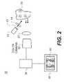
- FIG. 2is a schematic block diagram of an imaging apparatus for caries detection according to an alternate embodiment.
- FIG. 3is a schematic block diagram of an imaging apparatus for caries detection according to an alternate embodiment.
- FIG. 4Ais a schematic block diagram of an imaging apparatus for caries detection according to an alternate embodiment using polarized light.
- FIG. 4Bis a schematic block diagram of an imaging apparatus for caries detection according to an alternate embodiment using a polarizing beamsplitter to provide polarized light and to minimize specular reflection.
- FIG. 5is a view showing the process for combining dental image data to generate a fluorescence image with reflectance enhancement according to the present invention.
- FIG. 6is a composite view showing the contrast improvement of the present invention in a side-by-side comparison with conventional visual and fluorescence methods.
- FIG. 7is a block diagram showing a sequence of image processing for generating an enhanced threshold image according to one embodiment.
- FIG. 8is a schematic block diagram of an imaging apparatus for caries detection according to an alternate embodiment using multiple light sources.
- fluorescencecan be used to detect dental caries using either of two characteristic responses: First, excitation by a blue light source causes healthy tooth tissue to fluoresce in the green spectrum. Secondly, excitation by a red light source can cause bacterial by-products, such as those indicating caries, to fluoresce in the red spectrum.
- reflectanceIn order for an understanding of how light is used in the present invention, it is important to give more precise definition to the terms “reflectance” and “back-scattering” as they are used in biomedical applications in general and, more particularly, in the method and apparatus of the present invention.
- reflectancegenerally denotes the sum total of both specular reflectance and scattered reflectance. (Specular reflection is that component of the excitation light that is reflected by the tooth surface at the same angle as the incident angle.)
- specular component of reflectanceis of no interest and is, instead, generally detrimental to obtaining an image or measurement from a sample.
- the component of reflectance that is of interest for the present applicationis from back-scattered light only. Specular reflectance must be blocked or otherwise removed from the imaging path.
- the term “back-scattered reflectance”is used in the present application to denote the component of reflectance that is of interest. “Back-scattered reflectance” is defined as that component of the excitation light that is elastically back-scattered over a wide range of angles by the illuminated tooth structure.
- “Reflectance image” datarefers to image data obtained from back-scattered reflectance only, since specular reflectance is blocked or kept to a minimum. In the scientific literature, back-scattered reflectance may also be referred to as back-reflectance or simply as back-scattering. Back-scattered reflectance is at the same wavelength as the excitation light.
- the present inventiontakes advantage of the observed back-scattering behavior for incipient caries and uses this effect, in combination with fluorescence effects described previously in the background section, to provide an improved capability for dental imaging to detect caries.
- the inventive techniquehereafter referred to as fluorescence imaging with reflectance enhancement (FIRE)
- FIREfluorescence imaging with reflectance enhancement
- FIRE detectioncan be accurate at an earlier stage of caries infection than has been exhibited using existing fluorescence approaches that measure fluorescence alone.
- a light source 12directs an incident light, at a blue wavelength range or other suitable wavelength range, toward tooth 20 through an optional lens 14 or other light beam conditioning component.
- the tooth 20may be illuminated at a proximal surface (as shown) or at an occlusal surface (not shown).
- Two components of lightare then detected by a monochrome camera 30 through a lens 22 : a back-scattered light component having the same wavelength as the incident light and having measurable reflectance; and a fluorescent light that has been excited due to the incident light.
- specular reflectioncauses false positives and is undesirable.
- the camera 30is positioned at a suitable angle with respect to the light source 12 . This allows imaging of back-scattered light without the confounding influence of a specularly reflected component.
- monochrome camera 30has color filters 26 and 28 .
- One of color filters 26 and 28is used during reflectance imaging, the other is used during fluorescence imaging.
- a processing apparatus 38obtains and processes the reflectance and fluorescence image data and forms a FIRE image 60 .
- FIRE image 60is an enhanced diagnostic image that can be printed or can appear on a display 40 .
- FIRE image 60 datacan also be transmitted to storage or transmitted to another site for display.
- FIG. 2there is shown an alternate embodiment using a color camera 32 .
- auxiliary filterswould not generally be needed, since color camera 32 would be able to obtain the reflectance and fluorescence images from the color separations (also called color planes) of the full color image of tooth 20 .
- Light source 12is typically centered around a blue wavelength, such as about 405 nm in one embodiment. In practice, light source 12 could emit light ranging in wavelength from an upper ultraviolet range to a deeper blue, between about 300 and 500 nm.
- Light source 12can be a laser or could be fabricated using one or more light emitting diodes (LEDs). Alternately, a broadband source, such as a xenon lamp, having a supporting color filter for passing the desired wavelengths could be used.
- Lens 14 or other optical elementmay serve to condition the incident light, such as by controlling the uniformity and size of the illumination area. For example, a diffuser 13 , shown as a dotted line in FIG. 2 , might be used before or after lens 14 to smooth out the hot spots of an LED beam.
- the path of illumination lightmight include light guiding or light distributing structures such as optical fibers or a liquid light guide, for example (not shown).
- Light levelis typically a few milliwatts in intensity, but can be more or less, depending on the light conditioning and sensing components used.
- the illumination arrangementcould alternately direct light at normal incidence, turned through a beamsplitter 34 . Camera 32 would then be disposed to obtain the image light that is transmitted through beamsplitter 34 .
- Other options for illuminationinclude multiple light sources directed at the tooth with angular incidence from one or more sides. Alternately, the illumination might use an annular ring or an arrangement of LED sources distributed about a center such as in a circular array to provide light uniformly from multiple angles. Illumination could also be provided through an optical fiber or fiber array.
- the imaging opticscould include any suitable arrangement of optical components, with possible configurations ranging from a single lens component to a multi-element lens. Clear imaging of the tooth surface, which is not flat but can have areas that are both smoothly contoured and highly ridged, requires that imaging optics have sufficient depth of focus. Preferably, for optimal resolution, the imaging optics provide an image size that substantially fills the sensor element of the camera. Telecentric optics are advantaged for lens 22 , providing image-bearing light that is not highly dependent on ray angle.
- Image capturecan be performed by either monochrome camera 30 ( FIG. 1 ) or color camera 32 ( FIG. 2 ).
- camera 30 or 32employs a CMOS or CCD image sensor.
- the monochrome versionwould typically employ a retractable spectral filter 26 , 28 suitable for the wavelength of interest.
- spectral filter 26 for capturing reflectance image datawould transmit predominately blue light.
- Spectral filter 28 for capturing fluorescence image datawould transmit light at a different wavelength, such as predominately green light.
- spectral filters 26 and 28are automatically switched into place to allow capture of both reflectance and fluorescence images in very close succession. Both images are obtained from the same position to allow accurate registration of the image data.
- Spectral filter 28would be optimized with a pass-band that captures fluorescence data over a range of suitable wavelengths.
- the fluorescent effect that has been obtained from tooth 20can have a relative broad spectral distribution in the visible range, with light emitted that is outside the wavelength range of the light used for excitation.
- the fluorescent emissionis typically between about 450 nm and 650 nm, while generally peaking in the green region, roughly from around 500 nm to about 600 nm.
- a green light filteris generally preferred for spectral filter 28 in order to obtain this fluorescence image at its highest energy levels.
- other ranges of the visible spectrumcould also be used in other embodiments.
- spectral filter 26would be optimized with a pass-band that captures reflectance data over a wavelength range covering at least a significant portion of the spectral energy of the light source 12 used.
- a blue light filteris generally used for spectral filter 26 in order to obtain the reflectance image at its highest energy level.
- Camera controlsare suitably adjusted for obtaining each type of image. For example, when capturing the fluorescence image, it is necessary to make appropriate exposure adjustments for gain, shutter speed, and aperture, since this image may not be intense.
- color camera 32FIG. 2
- color filteringis performed by the color filter arrays on the camera image sensor. The reflectance image is captured in the blue color plane; simultaneously, the fluorescence image is captured in the green color plane. That is, a single exposure captures both back-scattered reflectance and fluorescence images.
- Processing apparatus 38is typically a computer workstation but may, in its broadest application, be any type of control logic processing component or system that is capable of obtaining image data from camera 30 or 32 and executing image processing algorithms upon that data to generate the FIRE image 60 data. Processing apparatus 38 may be local or may connect to image sensing components over a networked interface.
- FIG. 5there is shown, in schematic form, how the FIRE image 60 is formed according to the present invention.
- Two images of tooth 20are obtained, a green fluorescence image 50 and a blue reflectance image 52 .
- the reflectance light used for reflectance image 52 and its datais from back-scattered reflectance, with specular reflectance blocked or kept as low as possible.
- there is a carious region 58represented in phantom outline in each of images 50 , 52 , and 60 , that causes a slight decrease in fluorescence and a slight increase in reflectance.
- the carious region 58may be imperceptible or barely perceptible in either fluorescence image 50 or reflectance image 52 , taken individually.
- Processing apparatus 38operates upon the image data using an image processing algorithm as discussed below for both images 50 and 52 and provides FIRE image 60 as a result.
- the contrast between carious region 58 and sound tooth structureis heightened, so that a caries condition is made more visible in FIRE image 60 .
- FIG. 6shows the contrast improvement of the present invention in a side-by-side comparison with a visual white-light image 54 and conventional fluorescence methods.
- the carious region 58may look indistinct from the surrounding healthy tooth structure in white-light image 54 , either as perceived directly by eye or as captured by an intraoral camera.
- the carious region 58may show up as a very faint, hardly noticeable shadow.
- the FIRE image 60generated by the present invention, the same carious region 58 shows up as a darker, more detectable spot.
- the FIRE image 60offers greater diagnostic value.
- processing of the image datauses both the reflectance and fluorescence image data to generate a final image that can be used to identify carious areas of the tooth.
- this image processingperforms the following operation for each pixel: (m*F value ) ⁇ (n*R value ) (1) where m and n are suitable multipliers (positive coefficients) and F value and R value are the code values obtained from fluorescence and reflectance image data, respectively.
- Back-scattered reflectanceis higher (brighter) for image pixels in the carious region, yielding a higher reflectance value R value for these pixels than for surrounding pixels.
- the fluorescencemeanwhile, is lower (darker) for image pixels in the carious region, yielding a lower fluorescence value F value for these pixels than for surrounding pixels.
- the fluorescenceis considerably weaker in intensity compared to the reflectance.
- scalar multiplier n for reflectance value R valueis one.
- a thresholding operationexecuted using image processing techniques familiar to those skilled in the imaging arts, or some other suitable conditioning of the combined image data used for FIRE image 60 , may be used to further enhance the contrast between a carious region and sound tooth structure.
- FIG. 7there is shown, in block diagram form, a sequence of image processing for generating an enhanced threshold FIRE image 64 according to one embodiment. Fluorescence image 50 and reflectance image 52 are first combined to form FIRE image 60 , as described previously. A thresholding operation is next performed, providing threshold image 62 that defines more clearly the area of interest, carious region 58 .
- threshold image 62is combined with original FIRE image 60 to generate enhanced threshold FIRE image 64 .
- results of threshold detectioncan also be superimposed onto a white light image 54 ( FIG. 6 ) in order to definitively outline the location of a carious infection.
- m and nare dependent on the spectral content of the light source and the spectral response of the image capture system. There is variability in the center wavelength and spectral bandwidth from one LED to the next, for example. Similarly, variability exits in the spectral responses of the color filters and image sensors of different image capture systems. Such variations affect the relative magnitudes of the measured reflectance and fluorescence values. Therefore, it may be necessary to determine a different m and n value for each imaging apparatus 10 as a part of an initial calibration process. A calibration procedure used during the manufacturing of imaging apparatus 10 can then optimize the m and n values to provide the best possible contrast enhancement in the FIRE image that is formed.
- a spectral measurement of the light source 12 used for reflectance imagingis obtained. Then, spectral measurement is made of the fluorescent emission that is excited from the tooth. This data provides a profile of the relative amount of light energy available over each wavelength range of interest. Then the spectral response of camera 30 (with appropriate filters) or 32 is quantified against a known reference. These data are then used, for example, to generate a set of optimized multiplier m and n values to be used by processing apparatus 38 of the particular imaging apparatus 10 for forming FIRE image 60 .
- any number of more complex image processing algorithmscould alternately be used for combining the reflectance and fluorescence image data in order to obtain an enhanced image that identifies carious regions more clearly. It may be advantageous to apply a number of different imaging algorithms to the image data in order to obtain the most useful result.
- an operatorcan elect to use any of a set of different image processing algorithms for conditioning the fluorescence and reflectance image data obtained. This would allow the operator to check the image data when processed in a number of different ways and may be helpful for optimizing the detection of carious lesions having different shape-related characteristics or that occur over different areas of the tooth surface.
- the image contrast enhancement achieved in the present inventionis advantaged over conventional methods that use fluorescent image data only.
- image processinghas been employed to optimize the data, such as to transform fluorescence data based on spectral response of the camera or of camera filters or other suitable characteristics.
- the method of the '2356 Stookey et al. disclosure, cited aboveperforms this type of optimization, transforming fluorescence image data based on camera response.
- these conventional approachesoverlook the added advantage of additional image information that the back-scattered reflectance data obtains.
- the contrast of either or both of the reflectance and fluorescence imagesmay be improved by the use of a polarizing element.
- enamelhaving a highly structured composition, is sensitive to the polarization of incident light.
- Polarized lighthas been used to improve the sensitivity of dental imaging techniques, for example, in “Imaging Caries Lesions and Lesion Progression with Polarization Sensitive Optical Coherence Tomography” in J. Biomed Opt ., October 2002; 7(4): pp. 618-27, by Fried et al.
- Polarization controlcan also be advantageously employed as a means to minimize specular reflection.
- Specular reflectiontends to preserve the polarization state of the incident light.
- the specular reflected lightis also S-polarized.
- Back-scatteringtends to de-polarize or randomize the polarization of the incident light.
- incident lightis S-polarized
- back-scattered lighthas both S- and P-polarization components. Using a polarizer and analyzer, this difference in polarization handling can be employed to help eliminate unwanted specular reflectance from the reflectance image, so that only back-scattered reflectance is obtained.
- FIG. 4Athere is shown an embodiment of imaging apparatus 10 that employs a polarizer 42 in the path of illumination light.
- Polarizer 42passes linearly polarized incident light.
- An analyzer 44may be provided in the path of image-bearing light from tooth 20 as a means to minimize specular reflection component.
- reflectance light sensed by camera 30 or 32is predominantly back-scattered light, that portion of the reflectance that is desirable for combination with the fluorescence image data according to the present invention.
- polarizer 42In the case where the illumination light from light source 12 is already linearly polarized, such as from a laser, polarizer 42 is not needed; analyzer 44 would then be oriented with its polarization axis orthogonal to the polarization direction of the illumination light for rejecting specular reflection.
- FIG. 4BAn alternate embodiment, shown in FIG. 4B , employs a polarizing beamsplitter 18 (sometimes termed a polarization beamsplitter) as a polarizing element.
- polarizing beamsplitter 18advantageously performs the functions of both the polarizer and the analyzer for image-bearing light, thus offering a more compact solution. Tracing the path of illumination and image-bearing light shows how polarizing beamsplitter 18 performs this function.
- Polarization beamsplitter 18transmits P-polarization, as shown by the dotted arrow in FIG. 4B , and reflects S-polarization, directing this light to tooth 20 . Back-scattering by the tooth 20 structure depolarizes this light.
- Polarization beamsplitter 18treats the back-scattered light in the same manner, transmitting the P-polarization and reflecting the S-polarization. The resulting P-polarized light can then be detected at camera 30 (with suitable filter as was described with reference to FIG. 1 ) or color camera 32 . Because specularly reflected light is S-polarized, polarization beamsplitter 18 effectively removes this specular reflective component from the light that reaches camera 30 , 32 .
- Polarized illuminationresults in further improvement in image contrast, but at the expense of light level, as can be seen from the description of FIGS. 4A and 4B .
- polarizer 42One type of polarizer 42 that has particular advantages for use in the present application is the wire grid polarizer, such as those available from Moxtek Inc. of Orem, Utah and described in U.S. Pat. No. 6,122,103 (Perkins et al.)
- the wire grid polarizerexhibits good angular and color response, with relatively good transmission over the blue spectral range.
- Either or both polarizer 42 and analyzer 44 in the configuration of FIG. 4Acould be wire grid polarizers.
- Wire grid polarizing beamsplittersare also available, and can be used in the configuration of FIG. 4B .
- the method of the present inventiontakes advantage of the way the tooth tissue responds to incident light of sufficient intensity, using the combination of fluorescence and light reflectance to indicate carious areas of the tooth with improved accuracy and clarity.
- the present inventionoffers an improvement upon existing non-invasive fluorescence detection techniques for caries.
- images that have been obtained using fluorescence onlymay not clearly show caries due to low contrast.
- the method of the present inventionprovides images having improved contrast and is, therefore, of more potential benefit to the diagnostician for identifying caries.
- the method of the present inventionalso provides images that can be used to detect caries in its very early incipient stages. This added capability, made possible because of the perceptible back-scattering effects for very early carious lesions, extends the usefulness of the fluorescence technique and helps in detecting caries during its reversible stages, so that fillings or other restorative strategies might not be needed.
- light sources 12could be used, with various different embodiments employing a camera or other type of image sensor. While a single light source 12 could be used for fluorescence excitation, it may be beneficial to apply light from multiple incident light sources 12 for obtaining multiple images.
- light source 12might be a more complex assembly that includes one light source 16 a for providing light of appropriate energy level and wavelength for exciting fluorescent emission and another light source 16 b for providing illumination at different times.
- the additional light source 16 bcould provide light at wavelength and energy levels best suited for back-scattered reflectance imaging.
- white light illuminationor other polychromatic illumination
- the white light imageitself might also provide the back-scattered reflectance data that is used with the fluorescence data for generating the FIRE image.
- Supporting optics for both illumination and image-bearing light pathscould have any number of forms.
- a variety of support componentscould be fitted about the tooth and used by the dentist or dental technician who obtains the images. Such components might be used, for example, to appropriately position the light source or sensing elements or to ease patient discomfort during imaging.
Landscapes
- Health & Medical Sciences (AREA)
- Life Sciences & Earth Sciences (AREA)
- Engineering & Computer Science (AREA)
- Biomedical Technology (AREA)
- General Health & Medical Sciences (AREA)
- Molecular Biology (AREA)
- Public Health (AREA)
- Dentistry (AREA)
- Oral & Maxillofacial Surgery (AREA)
- Physics & Mathematics (AREA)
- Veterinary Medicine (AREA)
- Biophysics (AREA)
- Pathology (AREA)
- Heart & Thoracic Surgery (AREA)
- Medical Informatics (AREA)
- Audiology, Speech & Language Pathology (AREA)
- Surgery (AREA)
- Animal Behavior & Ethology (AREA)
- Multimedia (AREA)
- Signal Processing (AREA)
- Investigating, Analyzing Materials By Fluorescence Or Luminescence (AREA)
- Dental Tools And Instruments Or Auxiliary Dental Instruments (AREA)
Abstract
Description
- U.S. Pat. No. 4,515,476 (Ingmar) discloses use of a laser for providing excitation energy that generates fluorescence at some other wavelength for locating carious areas.
- U.S. Pat. No. 6,231,338 (de Josselin de Jong et al.) discloses an imaging apparatus for identifying dental caries using fluorescence detection.
- U.S. Patent Application Publication No. 2004/0240716 (de Josselin de Jong et al.) discloses methods for improved image analysis for images obtained from fluorescing tissue.
- U.S. Pat. No. 4,479,499 (Alfano) describes a method for using transillumination to detect caries based on the translucent properties of tooth structure.
(m*Fvalue)−(n*Rvalue) (1)
where m and n are suitable multipliers (positive coefficients) and Fvalueand Rvalueare the code values obtained from fluorescence and reflectance image data, respectively.
(m*Fvalue)> or =(n*Rvalue). (2)
Subtraction of the scaled back-scattered reflectance value from the scaled fluorescence value for each pixel then results in a processed image where the contrast between the intensity values for pixels in the carious region and pixels in sound region is accentuated, resulting in a contrast enhancement that can be readily displayed and recognized. In one embodiment, scalar multiplier n for reflectance value Rvalueis one.
- 10 imaging apparatus
- 12 light source
- 13 diffuser
- 14 lens
- 16alight source
- 16blight source
- 18 polarizing beamsplitter
- 20 tooth
- 22 lens
- 26 filter
- 28 filter
- 30 camera
- 32 camera
- 34 beamsplitter
- 38 processing apparatus
- 40 display
- 42 polarizer
- 44 analyzer
- 50 fluorescence image
- 52 reflectance image
- 54 white-light image
- 58 carious region
- 60 FIRE image
- 62 threshold image
- 64 enhanced threshold FIRE image
Claims (16)
Priority Applications (2)
| Application Number | Priority Date | Filing Date | Title |
|---|---|---|---|
| US13/117,724US8345942B2 (en) | 2005-10-31 | 2011-05-27 | Method and apparatus for detection of caries |
| US13/686,081US9247241B2 (en) | 2005-10-31 | 2012-11-27 | Method and apparatus for detection of caries |
Applications Claiming Priority (3)
| Application Number | Priority Date | Filing Date | Title |
|---|---|---|---|
| US11/262,869US7596253B2 (en) | 2005-10-31 | 2005-10-31 | Method and apparatus for detection of caries |
| US12/541,329US7974453B2 (en) | 2005-10-31 | 2009-08-14 | Method and apparatus for detection of caries |
| US13/117,724US8345942B2 (en) | 2005-10-31 | 2011-05-27 | Method and apparatus for detection of caries |
Related Parent Applications (1)
| Application Number | Title | Priority Date | Filing Date |
|---|---|---|---|
| US12/541,329DivisionUS7974453B2 (en) | 2005-10-31 | 2009-08-14 | Method and apparatus for detection of caries |
Related Child Applications (1)
| Application Number | Title | Priority Date | Filing Date |
|---|---|---|---|
| US13/686,081ContinuationUS9247241B2 (en) | 2005-10-31 | 2012-11-27 | Method and apparatus for detection of caries |
Publications (2)
| Publication Number | Publication Date |
|---|---|
| US20110228066A1 US20110228066A1 (en) | 2011-09-22 |
| US8345942B2true US8345942B2 (en) | 2013-01-01 |
Family
ID=37714246
Family Applications (5)
| Application Number | Title | Priority Date | Filing Date |
|---|---|---|---|
| US11/262,869Active2027-06-30US7596253B2 (en) | 2005-10-31 | 2005-10-31 | Method and apparatus for detection of caries |
| US12/541,329Expired - Fee RelatedUS7974453B2 (en) | 2005-10-31 | 2009-08-14 | Method and apparatus for detection of caries |
| US13/117,759Expired - Fee RelatedUS8396272B2 (en) | 2005-10-31 | 2011-05-27 | Method and apparatus for detection of caries |
| US13/117,724Expired - Fee RelatedUS8345942B2 (en) | 2005-10-31 | 2011-05-27 | Method and apparatus for detection of caries |
| US13/686,081Active2026-04-29US9247241B2 (en) | 2005-10-31 | 2012-11-27 | Method and apparatus for detection of caries |
Family Applications Before (3)
| Application Number | Title | Priority Date | Filing Date |
|---|---|---|---|
| US11/262,869Active2027-06-30US7596253B2 (en) | 2005-10-31 | 2005-10-31 | Method and apparatus for detection of caries |
| US12/541,329Expired - Fee RelatedUS7974453B2 (en) | 2005-10-31 | 2009-08-14 | Method and apparatus for detection of caries |
| US13/117,759Expired - Fee RelatedUS8396272B2 (en) | 2005-10-31 | 2011-05-27 | Method and apparatus for detection of caries |
Family Applications After (1)
| Application Number | Title | Priority Date | Filing Date |
|---|---|---|---|
| US13/686,081Active2026-04-29US9247241B2 (en) | 2005-10-31 | 2012-11-27 | Method and apparatus for detection of caries |
Country Status (4)
| Country | Link |
|---|---|
| US (5) | US7596253B2 (en) |
| EP (1) | EP1942794A2 (en) |
| JP (1) | JP5441411B2 (en) |
| WO (1) | WO2007053293A2 (en) |
Cited By (1)
| Publication number | Priority date | Publication date | Assignee | Title |
|---|---|---|---|---|
| US20130302746A1 (en)* | 2006-09-12 | 2013-11-14 | Carestream Health, Inc. | Apparatus for caries detection |
Families Citing this family (110)
| Publication number | Priority date | Publication date | Assignee | Title |
|---|---|---|---|---|
| US11026768B2 (en) | 1998-10-08 | 2021-06-08 | Align Technology, Inc. | Dental appliance reinforcement |
| US7773802B2 (en) | 2002-07-26 | 2010-08-10 | Olympus Corporation | Image processing system with multiple imaging modes |
| EP1528380A4 (en) | 2002-07-26 | 2009-12-09 | Olympus Corp | Image processing system |
| EP1707928A4 (en)* | 2004-01-23 | 2011-03-09 | Olympus Corp | Image processing system and camera |
| US9492245B2 (en) | 2004-02-27 | 2016-11-15 | Align Technology, Inc. | Method and system for providing dynamic orthodontic assessment and treatment profiles |
| US7596253B2 (en)* | 2005-10-31 | 2009-09-29 | Carestream Health, Inc. | Method and apparatus for detection of caries |
| DE102006003126A1 (en)* | 2006-01-23 | 2007-08-02 | Siemens Ag | Method and device for visualizing 3D objects |
| US7668355B2 (en)* | 2006-08-31 | 2010-02-23 | Carestream Health, Inc. | Method for detection of caries |
| US8447087B2 (en) | 2006-09-12 | 2013-05-21 | Carestream Health, Inc. | Apparatus and method for caries detection |
| JP5073996B2 (en)* | 2006-09-20 | 2012-11-14 | オリンパス株式会社 | Image processing device |
| US7702139B2 (en)* | 2006-10-13 | 2010-04-20 | Carestream Health, Inc. | Apparatus for caries detection |
| US7878805B2 (en) | 2007-05-25 | 2011-02-01 | Align Technology, Inc. | Tabbed dental appliance |
| WO2009023872A1 (en)* | 2007-08-16 | 2009-02-19 | Magnified Video Dentistry, Inc. | Modular operatory led light and camera system |
| DE102007046228A1 (en)* | 2007-09-26 | 2009-04-09 | Degudent Gmbh | Method for detecting changes to at least one tooth |
| US8738394B2 (en) | 2007-11-08 | 2014-05-27 | Eric E. Kuo | Clinical data file |
| US7929151B2 (en) | 2008-01-11 | 2011-04-19 | Carestream Health, Inc. | Intra-oral camera for diagnostic and cosmetic imaging |
| US8866894B2 (en) | 2008-01-22 | 2014-10-21 | Carestream Health, Inc. | Method for real-time visualization of caries condition |
| US8108189B2 (en) | 2008-03-25 | 2012-01-31 | Align Technologies, Inc. | Reconstruction of non-visible part of tooth |
| US9492243B2 (en) | 2008-05-23 | 2016-11-15 | Align Technology, Inc. | Dental implant positioning |
| US8092215B2 (en) | 2008-05-23 | 2012-01-10 | Align Technology, Inc. | Smile designer |
| US8172569B2 (en) | 2008-06-12 | 2012-05-08 | Align Technology, Inc. | Dental appliance |
| US8152518B2 (en) | 2008-10-08 | 2012-04-10 | Align Technology, Inc. | Dental positioning appliance having metallic portion |
| EP2378955B1 (en)* | 2009-01-20 | 2021-08-25 | Carestream Dental Technology Topco Limited | Method and apparatus for detection of caries |
| US10603008B2 (en)* | 2009-02-19 | 2020-03-31 | Tessonics Corporation | Ultrasonic device for assessment of internal tooth structure |
| US8292617B2 (en) | 2009-03-19 | 2012-10-23 | Align Technology, Inc. | Dental wire attachment |
| DE102009020252B4 (en)* | 2009-05-07 | 2012-01-12 | Krohne Optosens Gmbh | Device for measuring the fluorescence of a medium |
| US8768016B2 (en)* | 2009-06-19 | 2014-07-01 | Carestream Health, Inc. | Method for quantifying caries |
| US8765031B2 (en) | 2009-08-13 | 2014-07-01 | Align Technology, Inc. | Method of forming a dental appliance |
| US8908936B2 (en)* | 2009-10-14 | 2014-12-09 | Carestream Health, Inc. | Method for extracting a carious lesion area |
| US9235901B2 (en)* | 2009-10-14 | 2016-01-12 | Carestream Health, Inc. | Method for locating an interproximal tooth region |
| US8687859B2 (en) | 2009-10-14 | 2014-04-01 | Carestream Health, Inc. | Method for identifying a tooth region |
| US9241774B2 (en) | 2010-04-30 | 2016-01-26 | Align Technology, Inc. | Patterned dental positioning appliance |
| US9211166B2 (en) | 2010-04-30 | 2015-12-15 | Align Technology, Inc. | Individualized orthodontic treatment index |
| US9579073B2 (en) | 2010-05-07 | 2017-02-28 | Apteryx, Inc. | System and method for dentition specific image enhancement |
| US9642687B2 (en) | 2010-06-15 | 2017-05-09 | The Procter & Gamble Company | Methods for whitening teeth |
| US9436868B2 (en)* | 2010-09-10 | 2016-09-06 | Dimensional Photonics International, Inc. | Object classification for measured three-dimensional object scenes |
| KR101260291B1 (en)* | 2010-11-09 | 2013-05-10 | 연세대학교 원주산학협력단 | Dental multi diagnosis system based on optical properties for dental disease |
| US8416984B2 (en) | 2011-01-20 | 2013-04-09 | Carestream Health, Inc. | Automatic tooth charting using digital images |
| US20130034823A1 (en)* | 2011-08-02 | 2013-02-07 | Rongguang Liang | Adaptive illumination method and apparatus for dental shade matching |
| JP5796408B2 (en)* | 2011-08-24 | 2015-10-21 | オムロンヘルスケア株式会社 | Oral care device |
| US9403238B2 (en) | 2011-09-21 | 2016-08-02 | Align Technology, Inc. | Laser cutting |
| EP2578200B1 (en) | 2011-10-04 | 2018-03-28 | VOCO GmbH | Compounds for infiltrating and/or sealing of dental hard substance and method |
| US9375300B2 (en) | 2012-02-02 | 2016-06-28 | Align Technology, Inc. | Identifying forces on a tooth |
| US8998609B2 (en)* | 2012-02-11 | 2015-04-07 | The Board Of Trustees Of The Leland Stanford Jr. University | Techniques for standardized imaging of oral cavity |
| US9220580B2 (en) | 2012-03-01 | 2015-12-29 | Align Technology, Inc. | Determining a dental treatment difficulty |
| US9414897B2 (en) | 2012-05-22 | 2016-08-16 | Align Technology, Inc. | Adjustment of tooth position in a virtual dental model |
| WO2014111990A1 (en)* | 2013-01-21 | 2014-07-24 | コニカミノルタ株式会社 | Probe, spectrometry device and diagnostic system |
| WO2015069704A1 (en)* | 2013-11-06 | 2015-05-14 | Carestream Health, Inc. | Periodontal disease detection system and method |
| US10772506B2 (en) | 2014-07-07 | 2020-09-15 | Align Technology, Inc. | Apparatus for dental confocal imaging |
| US9675430B2 (en) | 2014-08-15 | 2017-06-13 | Align Technology, Inc. | Confocal imaging apparatus with curved focal surface |
| US9610141B2 (en) | 2014-09-19 | 2017-04-04 | Align Technology, Inc. | Arch expanding appliance |
| US10449016B2 (en) | 2014-09-19 | 2019-10-22 | Align Technology, Inc. | Arch adjustment appliance |
| WO2016073569A2 (en) | 2014-11-05 | 2016-05-12 | Carestream Health, Inc. | Video detection of tooth condition using green and red fluorescence |
| US9870613B2 (en) | 2014-11-05 | 2018-01-16 | Carestream Health, Inc. | Detection of tooth condition using reflectance images with red and green fluorescence |
| US9744001B2 (en) | 2014-11-13 | 2017-08-29 | Align Technology, Inc. | Dental appliance with cavity for an unerupted or erupting tooth |
| EP3232898A1 (en) | 2014-12-17 | 2017-10-25 | Carestream Health, Inc. | Intra-oral 3-d fluorescence imaging |
| JP2016122912A (en)* | 2014-12-24 | 2016-07-07 | 日本電信電話株式会社 | Image acquisition device |
| US10504386B2 (en) | 2015-01-27 | 2019-12-10 | Align Technology, Inc. | Training method and system for oral-cavity-imaging-and-modeling equipment |
| US9547903B2 (en) | 2015-04-16 | 2017-01-17 | Carestream Health, Inc. | Method for quantifying caries |
| US10248883B2 (en) | 2015-08-20 | 2019-04-02 | Align Technology, Inc. | Photograph-based assessment of dental treatments and procedures |
| EP3263007A4 (en)* | 2015-10-22 | 2018-12-12 | Olympus Corporation | Endoscope system |
| US11554000B2 (en) | 2015-11-12 | 2023-01-17 | Align Technology, Inc. | Dental attachment formation structure |
| US11931222B2 (en) | 2015-11-12 | 2024-03-19 | Align Technology, Inc. | Dental attachment formation structures |
| BR112018011227B1 (en)* | 2015-12-04 | 2021-07-20 | 3Shape A/S | METHOD FOR COMPLETING A DIGITAL DENTAL CHART WITH DENTAL CONDITION INFORMATION FOR A PATIENT'S TEETH |
| US11596502B2 (en) | 2015-12-09 | 2023-03-07 | Align Technology, Inc. | Dental attachment placement structure |
| US11103330B2 (en) | 2015-12-09 | 2021-08-31 | Align Technology, Inc. | Dental attachment placement structure |
| CN105852790A (en)* | 2016-04-26 | 2016-08-17 | 郑洪� | Endoscopic device and endoscope |
| WO2017218947A1 (en) | 2016-06-17 | 2017-12-21 | Align Technology, Inc. | Intraoral appliances with sensing |
| US10383705B2 (en) | 2016-06-17 | 2019-08-20 | Align Technology, Inc. | Orthodontic appliance performance monitor |
| CA3030676A1 (en) | 2016-07-27 | 2018-02-01 | Align Technology, Inc. | Intraoral scanner with dental diagnostics capabilities |
| US10507087B2 (en) | 2016-07-27 | 2019-12-17 | Align Technology, Inc. | Methods and apparatuses for forming a three-dimensional volumetric model of a subject's teeth |
| CN117257492A (en) | 2016-11-04 | 2023-12-22 | 阿莱恩技术有限公司 | Method and apparatus for dental imaging |
| EP3547952B1 (en) | 2016-12-02 | 2020-11-04 | Align Technology, Inc. | Palatal expander |
| WO2018102770A1 (en) | 2016-12-02 | 2018-06-07 | Align Technology, Inc. | Force control, stop mechanism, regulating structure of removable arch adjustment appliance |
| AU2017366755B2 (en) | 2016-12-02 | 2022-07-28 | Align Technology, Inc. | Methods and apparatuses for customizing rapid palatal expanders using digital models |
| US11026831B2 (en) | 2016-12-02 | 2021-06-08 | Align Technology, Inc. | Dental appliance features for speech enhancement |
| US10548700B2 (en) | 2016-12-16 | 2020-02-04 | Align Technology, Inc. | Dental appliance etch template |
| US10456043B2 (en) | 2017-01-12 | 2019-10-29 | Align Technology, Inc. | Compact confocal dental scanning apparatus |
| US10779718B2 (en) | 2017-02-13 | 2020-09-22 | Align Technology, Inc. | Cheek retractor and mobile device holder |
| WO2018183358A1 (en) | 2017-03-27 | 2018-10-04 | Align Technology, Inc. | Apparatuses and methods assisting in dental therapies |
| US10613515B2 (en) | 2017-03-31 | 2020-04-07 | Align Technology, Inc. | Orthodontic appliances including at least partially un-erupted teeth and method of forming them |
| US11045283B2 (en) | 2017-06-09 | 2021-06-29 | Align Technology, Inc. | Palatal expander with skeletal anchorage devices |
| CN116942335A (en) | 2017-06-16 | 2023-10-27 | 阿莱恩技术有限公司 | Automatic detection of tooth type and eruption status |
| KR102573669B1 (en)* | 2017-06-21 | 2023-09-04 | 코닌클리케 필립스 엔.브이. | Method and device for early caries detection |
| US10639134B2 (en) | 2017-06-26 | 2020-05-05 | Align Technology, Inc. | Biosensor performance indicator for intraoral appliances |
| US10885521B2 (en) | 2017-07-17 | 2021-01-05 | Align Technology, Inc. | Method and apparatuses for interactive ordering of dental aligners |
| CN111107806B (en) | 2017-07-21 | 2022-04-19 | 阿莱恩技术有限公司 | Jaw profile anchoring |
| EP4278957A3 (en) | 2017-07-27 | 2024-01-24 | Align Technology, Inc. | System and methods for processing an orthodontic aligner by means of an optical coherence tomography |
| CN110996842B (en) | 2017-07-27 | 2022-10-14 | 阿莱恩技术有限公司 | Tooth Staining, Transparency and Glazing |
| US12274597B2 (en)* | 2017-08-11 | 2025-04-15 | Align Technology, Inc. | Dental attachment template tray systems |
| US11116605B2 (en) | 2017-08-15 | 2021-09-14 | Align Technology, Inc. | Buccal corridor assessment and computation |
| US11123156B2 (en) | 2017-08-17 | 2021-09-21 | Align Technology, Inc. | Dental appliance compliance monitoring |
| US12171575B2 (en) | 2017-10-04 | 2024-12-24 | Align Technology, Inc. | Intraoral systems and methods for sampling soft-tissue |
| US10813720B2 (en) | 2017-10-05 | 2020-10-27 | Align Technology, Inc. | Interproximal reduction templates |
| CN111565668B (en) | 2017-10-27 | 2022-06-07 | 阿莱恩技术有限公司 | Substitute occlusion adjusting structure |
| CN111295153B (en) | 2017-10-31 | 2023-06-16 | 阿莱恩技术有限公司 | Dental appliance with selective bite loading and controlled tip staggering |
| CN119235481A (en) | 2017-11-01 | 2025-01-03 | 阿莱恩技术有限公司 | Automatic treatment planning |
| US11534974B2 (en) | 2017-11-17 | 2022-12-27 | Align Technology, Inc. | Customized fabrication of orthodontic retainers based on patient anatomy |
| US11219506B2 (en) | 2017-11-30 | 2022-01-11 | Align Technology, Inc. | Sensors for monitoring oral appliances |
| US11432908B2 (en) | 2017-12-15 | 2022-09-06 | Align Technology, Inc. | Closed loop adaptive orthodontic treatment methods and apparatuses |
| US10980613B2 (en) | 2017-12-29 | 2021-04-20 | Align Technology, Inc. | Augmented reality enhancements for dental practitioners |
| US10813727B2 (en) | 2018-01-26 | 2020-10-27 | Align Technology, Inc. | Diagnostic intraoral tracking |
| DK179936B1 (en) | 2018-03-12 | 2019-10-14 | Angle.Design ApS | Tool for Assisting the Process of Marking or Cutting |
| US11937991B2 (en) | 2018-03-27 | 2024-03-26 | Align Technology, Inc. | Dental attachment placement structure |
| EP3773320B1 (en) | 2018-04-11 | 2024-05-15 | Align Technology, Inc. | Releasable palatal expanders |
| TWI667999B (en)* | 2018-05-17 | 2019-08-11 | 廣達電腦股份有限公司 | Method and device for dynamically adjusting fluorescent imaging |
| US11389131B2 (en) | 2018-06-27 | 2022-07-19 | Denti.Ai Technology Inc. | Systems and methods for processing of dental images |
| US11464467B2 (en)* | 2018-10-30 | 2022-10-11 | Dgnct Llc | Automated tooth localization, enumeration, and diagnostic system and method |
| US10991091B2 (en)* | 2018-10-30 | 2021-04-27 | Diagnocat Inc. | System and method for an automated parsing pipeline for anatomical localization and condition classification |
| JP7444978B2 (en)* | 2019-11-07 | 2024-03-06 | コルゲート・パーモリブ・カンパニー | Multimodal imaging system and method therefor |
Citations (21)
| Publication number | Priority date | Publication date | Assignee | Title |
|---|---|---|---|---|
| US4479499A (en) | 1982-01-29 | 1984-10-30 | Alfano Robert R | Method and apparatus for detecting the presence of caries in teeth using visible light |
| US4515476A (en) | 1981-04-01 | 1985-05-07 | Bjelkhagen Hans Ingmar | Device for the ocular determination of any discrepancy in the luminescence capacity of the surface of a tooth for the purpose of identifying any caried area on the surface to the tooth |
| WO1995026673A2 (en) | 1994-03-28 | 1995-10-12 | Xillix Technologies Corporation | Apparatus and method for imaging diseased tissue using integrated autofluorescence |
| US6038024A (en) | 1998-01-09 | 2000-03-14 | Mht Optic Research | Method and an apparatus for determining the color stimulus specification of an object |
| US6122103A (en) | 1999-06-22 | 2000-09-19 | Moxtech | Broadband wire grid polarizer for the visible spectrum |
| US6231338B1 (en) | 1999-05-10 | 2001-05-15 | Inspektor Research Systems B.V. | Method and apparatus for the detection of carious activity of a carious lesion in a tooth |
| US20020021439A1 (en)* | 2000-08-07 | 2002-02-21 | Derek Priestley | Colour matching system |
| JP2002143080A (en) | 2000-11-10 | 2002-05-21 | Asahi Optical Co Ltd | Electronic endoscope device |
| WO2002096281A1 (en) | 2001-06-01 | 2002-12-05 | Centre National De La Recherche Scientifique | Method and device for the acquisition and treatment of dental images |
| WO2003005892A2 (en) | 2001-07-10 | 2003-01-23 | Ferton Holding Sa | Method and device for recognizing dental caries, plaque, concrements or bacterial attacks |
| US20040023184A1 (en) | 2002-07-31 | 2004-02-05 | De Josselin De Jong Elbert | Dental implement and method for tooth surface inspection |
| JP2004237081A (en) | 2003-01-14 | 2004-08-26 | Morita Mfg Co Ltd | Diagnostic imaging equipment |
| US20040202356A1 (en) | 2003-04-10 | 2004-10-14 | Stookey George K. | Optical detection of dental caries |
| US20040240716A1 (en) | 2003-05-22 | 2004-12-02 | De Josselin De Jong Elbert | Analysis and display of fluorescence images |
| US20050003323A1 (en)* | 2003-01-14 | 2005-01-06 | J. Morita Manufacturing Corporation | Diagnostic imaging apparatus |
| WO2005002429A1 (en) | 2003-06-17 | 2005-01-13 | Centre National De La Recherche Scientifique | Method and device for recording and processing images of an object such as a tooth |
| US20050032720A1 (en)* | 2003-08-06 | 2005-02-10 | Regenacorp, Inc. | Method and composition for treating peridontal disease |
| JP2005304600A (en) | 2004-04-19 | 2005-11-04 | Morita Mfg Co Ltd | Living body observation equipment, intraoral imaging device, medical frame device and dental mirror |
| US7030986B2 (en) | 1999-12-08 | 2006-04-18 | X-Rite Incorporated | Optical measurement device and related process |
| WO2006063246A1 (en) | 2004-12-08 | 2006-06-15 | The General Hospital Corporation | System and method for normalized fluorescence or bioluminescence imaging |
| US7064830B2 (en) | 2003-06-12 | 2006-06-20 | Eastman Kodak Company | Dental color imaging system |
Family Cites Families (6)
| Publication number | Priority date | Publication date | Assignee | Title |
|---|---|---|---|---|
| US4290433A (en) | 1979-08-20 | 1981-09-22 | Alfano Robert R | Method and apparatus for detecting the presence of caries in teeth using visible luminescence |
| US6519037B2 (en)* | 1999-12-23 | 2003-02-11 | Lj Laboratories, Llc | Spectrometer having optical unit including a randomized fiber optic implement |
| JP3520275B2 (en)* | 2001-01-26 | 2004-04-19 | ゼブラ株式会社 | Decolorable or discolorable aqueous ink and method for producing the same |
| JP2005069807A (en)* | 2003-08-22 | 2005-03-17 | Matsushita Electric Ind Co Ltd | Tooth surface observation device |
| JP2005319116A (en)* | 2004-05-10 | 2005-11-17 | Pentax Corp | Fluorescence observation endoscope device |
| US7596253B2 (en)* | 2005-10-31 | 2009-09-29 | Carestream Health, Inc. | Method and apparatus for detection of caries |
- 2005
- 2005-10-31USUS11/262,869patent/US7596253B2/enactiveActive
- 2006
- 2006-10-16JPJP2008537765Apatent/JP5441411B2/ennot_activeExpired - Fee Related
- 2006-10-16WOPCT/US2006/040472patent/WO2007053293A2/enactiveApplication Filing
- 2006-10-16EPEP06826069Apatent/EP1942794A2/ennot_activeWithdrawn
- 2009
- 2009-08-14USUS12/541,329patent/US7974453B2/ennot_activeExpired - Fee Related
- 2011
- 2011-05-27USUS13/117,759patent/US8396272B2/ennot_activeExpired - Fee Related
- 2011-05-27USUS13/117,724patent/US8345942B2/ennot_activeExpired - Fee Related
- 2012
- 2012-11-27USUS13/686,081patent/US9247241B2/enactiveActive
Patent Citations (26)
| Publication number | Priority date | Publication date | Assignee | Title |
|---|---|---|---|---|
| US4515476A (en) | 1981-04-01 | 1985-05-07 | Bjelkhagen Hans Ingmar | Device for the ocular determination of any discrepancy in the luminescence capacity of the surface of a tooth for the purpose of identifying any caried area on the surface to the tooth |
| US4479499A (en) | 1982-01-29 | 1984-10-30 | Alfano Robert R | Method and apparatus for detecting the presence of caries in teeth using visible light |
| WO1995026673A2 (en) | 1994-03-28 | 1995-10-12 | Xillix Technologies Corporation | Apparatus and method for imaging diseased tissue using integrated autofluorescence |
| JPH10500588A (en) | 1994-03-28 | 1998-01-20 | ジリックス・テクノロジイズ・コーポレーション | Apparatus and method for imaging diseased tissue using integrated internal fluorescence |
| US6038024A (en) | 1998-01-09 | 2000-03-14 | Mht Optic Research | Method and an apparatus for determining the color stimulus specification of an object |
| US6231338B1 (en) | 1999-05-10 | 2001-05-15 | Inspektor Research Systems B.V. | Method and apparatus for the detection of carious activity of a carious lesion in a tooth |
| US6122103A (en) | 1999-06-22 | 2000-09-19 | Moxtech | Broadband wire grid polarizer for the visible spectrum |
| US7030986B2 (en) | 1999-12-08 | 2006-04-18 | X-Rite Incorporated | Optical measurement device and related process |
| US20020021439A1 (en)* | 2000-08-07 | 2002-02-21 | Derek Priestley | Colour matching system |
| JP2002143080A (en) | 2000-11-10 | 2002-05-21 | Asahi Optical Co Ltd | Electronic endoscope device |
| US20040236232A1 (en) | 2001-06-01 | 2004-11-25 | Centre National De La Recherche Scientifique | Method and apparatus for acquiring and processing images of a tooth |
| WO2002096281A1 (en) | 2001-06-01 | 2002-12-05 | Centre National De La Recherche Scientifique | Method and device for the acquisition and treatment of dental images |
| JP2004526550A (en) | 2001-06-01 | 2004-09-02 | サントル・ナショナル・ドゥ・ラ・レシェルシュ・サイエンティフィーク | Method and apparatus for acquiring and processing dental images |
| WO2003005892A2 (en) | 2001-07-10 | 2003-01-23 | Ferton Holding Sa | Method and device for recognizing dental caries, plaque, concrements or bacterial attacks |
| US20030156788A1 (en) | 2001-07-10 | 2003-08-21 | Thomas Henning | Method and device for recognizing dental caries, plaque, concrements or bacterial attacks |
| US20040023184A1 (en) | 2002-07-31 | 2004-02-05 | De Josselin De Jong Elbert | Dental implement and method for tooth surface inspection |
| US20050003323A1 (en)* | 2003-01-14 | 2005-01-06 | J. Morita Manufacturing Corporation | Diagnostic imaging apparatus |
| JP2004237081A (en) | 2003-01-14 | 2004-08-26 | Morita Mfg Co Ltd | Diagnostic imaging equipment |
| US20040202356A1 (en) | 2003-04-10 | 2004-10-14 | Stookey George K. | Optical detection of dental caries |
| US20040240716A1 (en) | 2003-05-22 | 2004-12-02 | De Josselin De Jong Elbert | Analysis and display of fluorescence images |
| US7064830B2 (en) | 2003-06-12 | 2006-06-20 | Eastman Kodak Company | Dental color imaging system |
| WO2005002429A1 (en) | 2003-06-17 | 2005-01-13 | Centre National De La Recherche Scientifique | Method and device for recording and processing images of an object such as a tooth |
| US20050032720A1 (en)* | 2003-08-06 | 2005-02-10 | Regenacorp, Inc. | Method and composition for treating peridontal disease |
| JP2005304600A (en) | 2004-04-19 | 2005-11-04 | Morita Mfg Co Ltd | Living body observation equipment, intraoral imaging device, medical frame device and dental mirror |
| WO2006063246A1 (en) | 2004-12-08 | 2006-06-15 | The General Hospital Corporation | System and method for normalized fluorescence or bioluminescence imaging |
| JP2008522761A (en) | 2004-12-08 | 2008-07-03 | ザ・ゼネラル・ホスピタル・コーポレーション | Systems and methods for normalized fluorescence or bioluminescence imaging |
Non-Patent Citations (2)
| Title |
|---|
| Fried et al.; "Imaging caries lesions and lesion progression with polarization sensitive optical coherence tomography" Journal of Biomedical Optics 7(4), Oct. 2002, pp. 618-627. |
| WO2007/053293(A3)-PCT Search Report, dated Jun. 28, 2007 (6 pages). |
Cited By (2)
| Publication number | Priority date | Publication date | Assignee | Title |
|---|---|---|---|---|
| US20130302746A1 (en)* | 2006-09-12 | 2013-11-14 | Carestream Health, Inc. | Apparatus for caries detection |
| US9060690B2 (en)* | 2006-09-12 | 2015-06-23 | Carestream Health, Inc. | Apparatus for caries detection |
Also Published As
| Publication number | Publication date |
|---|---|
| US20110228066A1 (en) | 2011-09-22 |
| US20110228067A1 (en) | 2011-09-22 |
| US20090297003A1 (en) | 2009-12-03 |
| JP5441411B2 (en) | 2014-03-12 |
| EP1942794A2 (en) | 2008-07-16 |
| JP2009513249A (en) | 2009-04-02 |
| WO2007053293A2 (en) | 2007-05-10 |
| WO2007053293A3 (en) | 2007-08-09 |
| US9247241B2 (en) | 2016-01-26 |
| US7596253B2 (en) | 2009-09-29 |
| US7974453B2 (en) | 2011-07-05 |
| US20130083181A1 (en) | 2013-04-04 |
| US20070099148A1 (en) | 2007-05-03 |
| US8396272B2 (en) | 2013-03-12 |
Similar Documents
| Publication | Publication Date | Title |
|---|---|---|
| US8345942B2 (en) | Method and apparatus for detection of caries | |
| US8447083B2 (en) | Method for detection of caries | |
| US7577284B2 (en) | Optical detection of dental caries | |
| US10070791B2 (en) | Apparatus for caries detection | |
| US7702139B2 (en) | Apparatus for caries detection | |
| HK1134230B (en) | Method for detection of caries |
Legal Events
| Date | Code | Title | Description |
|---|---|---|---|
| FEPP | Fee payment procedure | Free format text:PAYOR NUMBER ASSIGNED (ORIGINAL EVENT CODE: ASPN); ENTITY STATUS OF PATENT OWNER: LARGE ENTITY | |
| STCF | Information on status: patent grant | Free format text:PATENTED CASE | |
| AS | Assignment | Owner name:CREDIT SUISSE AG, CAYMAN ISLANDS BRANCH, NEW YORK Free format text:AMENDED AND RESTATED INTELLECTUAL PROPERTY SECURITY AGREEMENT (FIRST LIEN);ASSIGNORS:CARESTREAM HEALTH, INC.;CARESTREAM DENTAL LLC;QUANTUM MEDICAL IMAGING, L.L.C.;AND OTHERS;REEL/FRAME:030711/0648 Effective date:20130607 | |
| AS | Assignment | Owner name:CREDIT SUISSE AG, CAYMAN ISLANDS BRANCH, NEW YORK Free format text:SECOND LIEN INTELLECTUAL PROPERTY SECURITY AGREEMENT;ASSIGNORS:CARESTREAM HEALTH, INC.;CARESTREAM DENTAL LLC;QUANTUM MEDICAL IMAGING, L.L.C.;AND OTHERS;REEL/FRAME:030724/0154 Effective date:20130607 | |
| FPAY | Fee payment | Year of fee payment:4 | |
| AS | Assignment | Owner name:CARESTREAM HEALTH, INC., NEW YORK Free format text:RELEASE BY SECURED PARTY;ASSIGNOR:CREDIT SUISSE AG, CAYMAN ISLANDS BRANCH;REEL/FRAME:043749/0243 Effective date:20170901 Owner name:RAYCO (SHANGHAI) MEDICAL PRODUCTS CO., LTD., CHINA Free format text:RELEASE BY SECURED PARTY;ASSIGNOR:CREDIT SUISSE AG, CAYMAN ISLANDS BRANCH;REEL/FRAME:043749/0243 Effective date:20170901 Owner name:CARESTREAM DENTAL LLC, GEORGIA Free format text:RELEASE BY SECURED PARTY;ASSIGNOR:CREDIT SUISSE AG, CAYMAN ISLANDS BRANCH;REEL/FRAME:043749/0243 Effective date:20170901 Owner name:CARESTREAM HEALTH LTD., ISRAEL Free format text:RELEASE BY SECURED PARTY;ASSIGNOR:CREDIT SUISSE AG, CAYMAN ISLANDS BRANCH;REEL/FRAME:043749/0133 Effective date:20170901 Owner name:CARESTREAM HEALTH FRANCE, FRANCE Free format text:RELEASE BY SECURED PARTY;ASSIGNOR:CREDIT SUISSE AG, CAYMAN ISLANDS BRANCH;REEL/FRAME:043749/0243 Effective date:20170901 Owner name:CARESTREAM HEALTH LTD., ISRAEL Free format text:RELEASE BY SECURED PARTY;ASSIGNOR:CREDIT SUISSE AG, CAYMAN ISLANDS BRANCH;REEL/FRAME:043749/0243 Effective date:20170901 Owner name:CARESTREAM DENTAL LLC, GEORGIA Free format text:RELEASE BY SECURED PARTY;ASSIGNOR:CREDIT SUISSE AG, CAYMAN ISLANDS BRANCH;REEL/FRAME:043749/0133 Effective date:20170901 Owner name:CARESTREAM HEALTH FRANCE, FRANCE Free format text:RELEASE BY SECURED PARTY;ASSIGNOR:CREDIT SUISSE AG, CAYMAN ISLANDS BRANCH;REEL/FRAME:043749/0133 Effective date:20170901 Owner name:RAYCO (SHANGHAI) MEDICAL PRODUCTS CO., LTD., CHINA Free format text:RELEASE BY SECURED PARTY;ASSIGNOR:CREDIT SUISSE AG, CAYMAN ISLANDS BRANCH;REEL/FRAME:043749/0133 Effective date:20170901 Owner name:CARESTREAM HEALTH, INC., NEW YORK Free format text:RELEASE BY SECURED PARTY;ASSIGNOR:CREDIT SUISSE AG, CAYMAN ISLANDS BRANCH;REEL/FRAME:043749/0133 Effective date:20170901 | |
| AS | Assignment | Owner name:CARESTREAM DENTAL TECHNOLOGY TOPCO LIMITED, UNITED KINGDOM Free format text:ASSIGNMENT OF ASSIGNORS INTEREST;ASSIGNOR:CARESTREAM HEALTH, INC.;REEL/FRAME:044873/0520 Effective date:20171027 Owner name:CARESTREAM DENTAL TECHNOLOGY TOPCO LIMITED, UNITED Free format text:ASSIGNMENT OF ASSIGNORS INTEREST;ASSIGNOR:CARESTREAM HEALTH, INC.;REEL/FRAME:044873/0520 Effective date:20171027 | |
| FEPP | Fee payment procedure | Free format text:MAINTENANCE FEE REMINDER MAILED (ORIGINAL EVENT CODE: REM.); ENTITY STATUS OF PATENT OWNER: LARGE ENTITY | |
| LAPS | Lapse for failure to pay maintenance fees | Free format text:PATENT EXPIRED FOR FAILURE TO PAY MAINTENANCE FEES (ORIGINAL EVENT CODE: EXP.); ENTITY STATUS OF PATENT OWNER: LARGE ENTITY | |
| STCH | Information on status: patent discontinuation | Free format text:PATENT EXPIRED DUE TO NONPAYMENT OF MAINTENANCE FEES UNDER 37 CFR 1.362 | |
| FP | Lapsed due to failure to pay maintenance fee | Effective date:20210101 | |
| AS | Assignment | Owner name:TROPHY DENTAL INC., NEW YORK Free format text:RELEASE OF SECURITY INTEREST IN INTELLECTUAL PROPERTY (FIRST LIEN);ASSIGNOR:CREDIT SUISSE AG, CAYMAN ISLANDS BRANCH;REEL/FRAME:061683/0441 Effective date:20220930 Owner name:QUANTUM MEDICAL IMAGING, L.L.C., NEW YORK Free format text:RELEASE OF SECURITY INTEREST IN INTELLECTUAL PROPERTY (FIRST LIEN);ASSIGNOR:CREDIT SUISSE AG, CAYMAN ISLANDS BRANCH;REEL/FRAME:061683/0441 Effective date:20220930 Owner name:CARESTREAM DENTAL LLC, GEORGIA Free format text:RELEASE OF SECURITY INTEREST IN INTELLECTUAL PROPERTY (FIRST LIEN);ASSIGNOR:CREDIT SUISSE AG, CAYMAN ISLANDS BRANCH;REEL/FRAME:061683/0441 Effective date:20220930 Owner name:CARESTREAM HEALTH, INC., NEW YORK Free format text:RELEASE OF SECURITY INTEREST IN INTELLECTUAL PROPERTY (FIRST LIEN);ASSIGNOR:CREDIT SUISSE AG, CAYMAN ISLANDS BRANCH;REEL/FRAME:061683/0441 Effective date:20220930 Owner name:TROPHY DENTAL INC., GEORGIA Free format text:RELEASE OF SECURITY INTEREST IN INTELLECTUAL PROPERTY (SECOND LIEN);ASSIGNOR:CREDIT SUISSE AG, CAYMAN ISLANDS BRANCH;REEL/FRAME:061683/0601 Effective date:20220930 Owner name:QUANTUM MEDICAL IMAGING, L.L.C., NEW YORK Free format text:RELEASE OF SECURITY INTEREST IN INTELLECTUAL PROPERTY (SECOND LIEN);ASSIGNOR:CREDIT SUISSE AG, CAYMAN ISLANDS BRANCH;REEL/FRAME:061683/0601 Effective date:20220930 Owner name:CARESTREAM DENTAL LLC, GEORGIA Free format text:RELEASE OF SECURITY INTEREST IN INTELLECTUAL PROPERTY (SECOND LIEN);ASSIGNOR:CREDIT SUISSE AG, CAYMAN ISLANDS BRANCH;REEL/FRAME:061683/0601 Effective date:20220930 Owner name:CARESTREAM HEALTH, INC., NEW YORK Free format text:RELEASE OF SECURITY INTEREST IN INTELLECTUAL PROPERTY (SECOND LIEN);ASSIGNOR:CREDIT SUISSE AG, CAYMAN ISLANDS BRANCH;REEL/FRAME:061683/0601 Effective date:20220930 |