US8345385B2 - Shield with continuously concave inner sidewall - Google Patents
Shield with continuously concave inner sidewallDownload PDFInfo
- Publication number
- US8345385B2 US8345385B2US12/915,267US91526710AUS8345385B2US 8345385 B2US8345385 B2US 8345385B2US 91526710 AUS91526710 AUS 91526710AUS 8345385 B2US8345385 B2US 8345385B2
- Authority
- US
- United States
- Prior art keywords
- main pole
- shield
- inner sidewall
- pole
- write head
- Prior art date
- Legal status (The legal status is an assumption and is not a legal conclusion. Google has not performed a legal analysis and makes no representation as to the accuracy of the status listed.)
- Expired - Fee Related
Links
Images


Classifications
- G—PHYSICS
- G11—INFORMATION STORAGE
- G11B—INFORMATION STORAGE BASED ON RELATIVE MOVEMENT BETWEEN RECORD CARRIER AND TRANSDUCER
- G11B5/00—Recording by magnetisation or demagnetisation of a record carrier; Reproducing by magnetic means; Record carriers therefor
- G11B5/127—Structure or manufacture of heads, e.g. inductive
- G11B5/1278—Structure or manufacture of heads, e.g. inductive specially adapted for magnetisations perpendicular to the surface of the record carrier
- G—PHYSICS
- G11—INFORMATION STORAGE
- G11B—INFORMATION STORAGE BASED ON RELATIVE MOVEMENT BETWEEN RECORD CARRIER AND TRANSDUCER
- G11B5/00—Recording by magnetisation or demagnetisation of a record carrier; Reproducing by magnetic means; Record carriers therefor
- G11B5/127—Structure or manufacture of heads, e.g. inductive
- G11B5/31—Structure or manufacture of heads, e.g. inductive using thin films
- G11B5/3109—Details
- G11B5/3116—Shaping of layers, poles or gaps for improving the form of the electrical signal transduced, e.g. for shielding, contour effect, equalizing, side flux fringing, cross talk reduction between heads or between heads and information tracks
- G—PHYSICS
- G11—INFORMATION STORAGE
- G11B—INFORMATION STORAGE BASED ON RELATIVE MOVEMENT BETWEEN RECORD CARRIER AND TRANSDUCER
- G11B5/00—Recording by magnetisation or demagnetisation of a record carrier; Reproducing by magnetic means; Record carriers therefor
- G11B5/127—Structure or manufacture of heads, e.g. inductive
- G11B5/31—Structure or manufacture of heads, e.g. inductive using thin films
- G11B5/3109—Details
- G11B5/313—Disposition of layers
- G11B5/3143—Disposition of layers including additional layers for improving the electromagnetic transducing properties of the basic structure, e.g. for flux coupling, guiding or shielding
- G11B5/3146—Disposition of layers including additional layers for improving the electromagnetic transducing properties of the basic structure, e.g. for flux coupling, guiding or shielding magnetic layers
- G11B5/315—Shield layers on both sides of the main pole, e.g. in perpendicular magnetic heads
- Y—GENERAL TAGGING OF NEW TECHNOLOGICAL DEVELOPMENTS; GENERAL TAGGING OF CROSS-SECTIONAL TECHNOLOGIES SPANNING OVER SEVERAL SECTIONS OF THE IPC; TECHNICAL SUBJECTS COVERED BY FORMER USPC CROSS-REFERENCE ART COLLECTIONS [XRACs] AND DIGESTS
- Y10—TECHNICAL SUBJECTS COVERED BY FORMER USPC
- Y10T—TECHNICAL SUBJECTS COVERED BY FORMER US CLASSIFICATION
- Y10T428/00—Stock material or miscellaneous articles
- Y10T428/11—Magnetic recording head
- Y10T428/1171—Magnetic recording head with defined laminate structural detail
- Y10T428/1186—Magnetic recording head with defined laminate structural detail with head pole component
Definitions
- a shield with inner wallssurrounds a main pole.
- the inner walls of the shieldhave wall angles with respect to a down track direction that exceed the wall angles of the main pole with respect to a down track direction.
- One embodiment of the shieldresembles a wine glass shaped cavity.
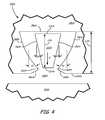
- FIG. 1is a cross sectional view of a perpendicular magnetic recording head according to an embodiment.
- FIG. 2is an air bearing surface view of a writer pole and “wine glass” shaped trailing shield according to an embodiment.
- FIG. 3is a plot of effective magnetic write field as a function of magnetic write width for a writer pole trailing shield with trapezoidal-shaped cavity and for the writer pole wine glass trailing shield cavity of FIG. 2 .
- FIG. 4is an air bearing surface view of a writer pole and wine glass trailing shield cavity according to an embodiment.
- FIG. 5is an air bearing surface view of a writer pole with wine glass trailing shield cavity according to an embodiment.
- FIG. 6is an air bearing surface view of a writer pole with trailing shield cavity with greater wall angles according to an embodiment.
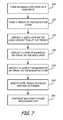
- FIG. 7provides a flowchart of an example magnetic element fabrication routine carried out in accordance with various embodiments.
- FIG. 1is a cross sectional view of an example perpendicular writer 10 in accordance with various embodiments, which includes main pole 12 , return pole 14 , and write coils 16 .
- Conductive write coils 16surround back gap closure 17 that magnetically couples main pole 12 to return pole 14 .
- Perpendicular writer 10confronts magnetic medium 18 at an air bearing surface (ABS) of main pole 12 and return pole 14 .
- Main pole 12includes main pole body 20 , yoke 21 , and main pole tip 22 .
- Yoke 21is coupled to an upper surface of main pole body 20 .
- Main pole tip 22has a leading edge 24 and a trailing edge 26 .
- Main pole tip 22is separated from return pole 14 at the ABS by insulating material 28 .
- Write gap 35is defined by the distance between leading edge 24 and return pole 14 .
- Magnetic medium 18may include magnetically soft underlayer 32 and magnetically hard recording layer 34 .
- perpendicular writer 10may include trailing shields, side shields, or wrap around shields that absorb stray magnetic fields from main pole tip 22 , magnetic side tracks on recording layer 34 , and other sources, such as the trailing edge of return pole 14 , during recording. Trailing shield 36 is shown proximate insulating layer 28 that surrounds main pole tip 22 of perpendicular writer 10 .
- Magnetic medium 18travels or rotates in a direction relative to perpendicular writer 10 as indicated by arrow A.
- an electric currentis caused to flow through conductive write coils 16 , which passes through write gap 35 , between main pole 12 and return pole 14 . This induces a magnetic field across write gap 35 .
- Main pole 12operates as the trailing pole and is used to physically write the data to magnetic medium 18 . Accordingly, it is main pole 12 that defines the track width of the written data. More specifically, the track width is defined by the width of trailing edge 26 of main pole tip 22 at the ABS.
- Main pole 12may be constructed of a material having a high saturation moment such as NiFe or CoFe or alloys thereof. More specifically, in various embodiments the main pole 12 is constructed as a lamination of layers of magnetic material separated by thin layers of nonmagnetic insulating material 28 such as, for example, aluminum oxide.
- FIG. 2is a schematic representation of an ABS view of perpendicular writer 110 .
- writer 110includes return pole 114 , main pole 122 , insulator 128 , and trailing shield 136 .
- Main pole 122has a trapezoidal pole tip with leading edge 124 , trailing edge 126 and sides 140 and 142 .
- shield 136includes inner sidewalls 150 and 152 , leading edge 154 , trailing edge 156 , throat sidewalls 162 and 164 , and mouth sidewalls 166 and 168 .
- Leading edge 154preferably is located closer to return pole 114 than is leading edge 124 of main pole 122 , wherein any stray field may be effectively prevented from reaching the magnetic medium.
- Inner sidewalls 150 and 152 of shield 136may not be parallel to sides 140 and 142 of main pole 122 .
- wall angles ⁇ 2 of shield 136may be larger than wall angles ⁇ 1 of main pole 122 .
- the trapezoidal shapeis narrower at leading edge 124 than at trailing edge 126 to aid in preventing skew related adjacent track interference during writing while the write head is located at inner and outer portions of a magnetic disc.
- throat sidewalls 162 and 164 and mouth sidewalls 166 and 168are adjacent leading edge 154 , thereby possibly minimizing magnetic field concentration in that vicinity during writing.
- the significance of increasing the wall angle and introducing throat sidewalls 162 and 164is that, as the size of main pole 122 decreases in response to a demand for higher areal density recording, the effective writing field of magnetic writer 110 may significantly exceed the effective writing field of a writer with a main pole having identical dimensions with shield walls parallel to main pole walls 142 .
- the shape of the cavity in shield 136 surrounding main pole 122 in writer 110resembles a wine glass.
- the length of main pole 122 , L 1may be less than the length of shield cavity L 2 and spacing S 1 toward the front of the cavity may be less than spacing S 2 at the back of the cavity.
- FIG. 3Exemplary results of such calculations are shown in FIG. 3 .
- the maximum effective write field H eff (max)is plotted versus the magnetic writer width.
- the datarepresent a series of H eff (max) for both writer configurations with identical write current, main pole wall angle, and main pole writer width.
- the average results for wine glass writer design 110are given by curve B.
- the wine glass designgave both consistently higher effective writing fields at a given magnetic write width and narrower magnetic write widths at the same write field.
- FIG. 4shows a schematic representation of an ABS view of an example perpendicular writer 110 A, which also features a shield with a wine glass shaped cavity.
- elements of writer 110 A that are similar to elements of writer 110are designated with the same reference number followed by the letter “A”.
- main pole 122 A of writer 110 Ais similar to main pole 122 of writer 110 .
- inner sidewalls 150 A and 152 A, throat sidewalls 162 A and 164 A, and mouth sidewalls 166 A and 168 A of shield 136 Aare concave, further minimizing magnetic field concentrations in the vicinity of the throat area defined by sidewalls 162 A and 164 A.
- Wall angles ⁇ 2 of sidewalls 150 A and 152 Amay be larger than wall angles ⁇ 1 of main pole 122 A.
- Length L 1 A of pole 122 Amay be less than length L 2 A of the shield cavity and spacing S 1 A toward the front of the cavity may be less than spacing S 2 at the back of the cavity. This design may result in greater effective magnetic fields during writing due to the narrower magnetic footprint of pole 122 A at the ABS.
- FIG. 5is a schematic representation of an ABS view of perpendicular writer 110 B illustrating another embodiment of the invention featuring a shield with a wineglass shaped cavity.
- Perpendicular writer 110 Bis similar to writers 110 and 110 A, and similar elements are designated with the same reference number followed by the letter “B”.
- shield 136 Bcompletely surrounds writer pole 122 B.
- the cavitydoes not extend to leading edge 154 B of shield 136 B.
- Leading end wall 170 B of the cavityis positioned near, but spaced from shield leading edge 154 B.
- Curved sidewalls 150 B and 152 B, throat sidewalls 162 B and 164 B, mouth sidewalls 166 B and 168 B and cavity leading end wall 170 Bresemble a wine glass.
- Length L 1 B of pole 122 Cmay be less than length L 2 B of the shield cavity and spacing S 1 B toward the front of the cavity may be less than spacing S 2 B at the back of the cavity.
- FIG. 6is a schematic representation of an ABS view of perpendicular writer 110 C illustrating another embodiment of the invention.
- Writer 110 Cis similar to writers 110 , 110 A, and 110 B, and similar elements are designated with the same reference number followed by the letter “C”.
- trailing shield 110 Ccompletely surrounds main pole 122 C and the cavity does not extend to leading edge 154 C of shield 110 C.
- Sidewalls 150 C and 152 Cform wall angles ⁇ 2 that are larger than wall angles ⁇ 1 of main pole 122 C.
- the cavityresembles a wine glass without a stem. That is, the cavity resembles the bowl of a wine glass.
- Length L 1 C of pole 122 Cmay be less than length L 2 C of the shield cavity and spacing S 1 C toward the front of the cavity may be less than length S 2 C at the back of the cavity.
- the wine glass writer designmay allow the magnetic write width to be varied by the shield geometry as well as by the main pole geometry. As shown in FIG. 3 , the magnetic writer width of any effective write field can be decreased by the inventive shield geometries disclosed herein. As a result, referring to FIG. 2 , for instance, leading edge 124 , trailing edge 126 and wall angles ⁇ 1 can be made smaller while pole 122 produces the same write field. Another benefit is that trapezoidal main poles with smaller wall angles are easier to fabricate, thereby decreasing the manufacturing costs.
- FIG. 7illustrates exemplary steps to form a pole in an insulator layer such as layer 128 in FIG. 2 .
- an insulator layeris formed on a substrate (Step 200 ).
- the insulator layeris preferably aluminum oxide although other insulator materials known in the art such as SiOx, MgO, SiC, etc. may be used.
- a trenchis formed in the insulator layer (Step 210 ).
- the cross section of the trenchis preferably trapezoidal as shown by pole 122 in FIG. 2 .
- a seedlayeris then deposited on the walls and bottom of the trench to assist in formation of pole 122 (Step 220 ).
- a seedlayeris necessary to control the quality of subsequent layers deposited in the trench and can be deposited by plating, sputtering, or other material deposition techniques.
- An electrically conducting seedlayeris necessary if subsequent layers are to be deposited by electroplating.
- a layer of magnetic materialis then deposited on the seedlayer (Step 230 ).
- NiFe, CoFe, or alloys thereofare preferred.
- the magnetic layercan be deposited by electroplating, sputtering, or other methods of material deposition. Laminated pole structures provide improved write performance.
- the next stepis to deposit a layer of nonmagnetic material on the magnetic material (Step 240 ).
- Nonmagnetic materials suitable for use as a spacer layerare tantalum, ruthenium, aluminum oxide, magnesium oxide, and others.
- the processis repeated until the trench is filled and the pole is formed (Step 250 ).
- the processthen proceeds to the next manufacturing cycle (Step 260 ).
Landscapes
- Engineering & Computer Science (AREA)
- Manufacturing & Machinery (AREA)
- Physics & Mathematics (AREA)
- Electromagnetism (AREA)
- Magnetic Heads (AREA)
Abstract
Description
Claims (20)
Priority Applications (7)
| Application Number | Priority Date | Filing Date | Title |
|---|---|---|---|
| US12/915,267US8345385B2 (en) | 2010-10-29 | 2010-10-29 | Shield with continuously concave inner sidewall |
| MYPI2011005152AMY158984A (en) | 2010-10-29 | 2011-10-25 | Shield with continuously concave inner sidewall |
| JP2011235831AJP5715929B2 (en) | 2010-10-29 | 2011-10-27 | Apparatus, write head, and method of recording magnetic data |
| CN201110346175.4ACN102467912B (en) | 2010-10-29 | 2011-10-28 | There is the screen of wine glass shaped cavity |
| US13/612,449US8472141B2 (en) | 2010-10-29 | 2012-09-12 | Shield with down-track throat region |
| US13/690,705US8675307B2 (en) | 2010-10-29 | 2012-11-30 | Shield with continuously and throat regions adjacent a main pole |
| JP2014240004AJP5981521B2 (en) | 2010-10-29 | 2014-11-27 | Apparatus comprising a shield having an inner sidewall |
Applications Claiming Priority (1)
| Application Number | Priority Date | Filing Date | Title |
|---|---|---|---|
| US12/915,267US8345385B2 (en) | 2010-10-29 | 2010-10-29 | Shield with continuously concave inner sidewall |
Related Child Applications (1)
| Application Number | Title | Priority Date | Filing Date |
|---|---|---|---|
| US13/612,449ContinuationUS8472141B2 (en) | 2010-10-29 | 2012-09-12 | Shield with down-track throat region |
Publications (2)
| Publication Number | Publication Date |
|---|---|
| US20120106001A1 US20120106001A1 (en) | 2012-05-03 |
| US8345385B2true US8345385B2 (en) | 2013-01-01 |
Family
ID=45996483
Family Applications (3)
| Application Number | Title | Priority Date | Filing Date |
|---|---|---|---|
| US12/915,267Expired - Fee RelatedUS8345385B2 (en) | 2010-10-29 | 2010-10-29 | Shield with continuously concave inner sidewall |
| US13/612,449Expired - Fee RelatedUS8472141B2 (en) | 2010-10-29 | 2012-09-12 | Shield with down-track throat region |
| US13/690,705ActiveUS8675307B2 (en) | 2010-10-29 | 2012-11-30 | Shield with continuously and throat regions adjacent a main pole |
Family Applications After (2)
| Application Number | Title | Priority Date | Filing Date |
|---|---|---|---|
| US13/612,449Expired - Fee RelatedUS8472141B2 (en) | 2010-10-29 | 2012-09-12 | Shield with down-track throat region |
| US13/690,705ActiveUS8675307B2 (en) | 2010-10-29 | 2012-11-30 | Shield with continuously and throat regions adjacent a main pole |
Country Status (4)
| Country | Link |
|---|---|
| US (3) | US8345385B2 (en) |
| JP (2) | JP5715929B2 (en) |
| CN (1) | CN102467912B (en) |
| MY (1) | MY158984A (en) |
Cited By (3)
| Publication number | Priority date | Publication date | Assignee | Title |
|---|---|---|---|---|
| US8830625B2 (en)* | 2012-11-29 | 2014-09-09 | Seagate Technology Llc | Data writer with tapered side shield sidewalls |
| US20150179192A1 (en)* | 2013-12-20 | 2015-06-25 | HGST Netherlands B.V. | Stray field shielding for perpendicular magnetic recording write head |
| US10643644B1 (en) | 2017-02-14 | 2020-05-05 | Seagate Technology Llc | Write pole with varied sidewall shape |
Families Citing this family (7)
| Publication number | Priority date | Publication date | Assignee | Title |
|---|---|---|---|---|
| US8830626B2 (en) | 2012-12-03 | 2014-09-09 | Seagate Technology Llc | Write pole with shaped box shield |
| US20140300995A1 (en)* | 2013-04-04 | 2014-10-09 | Seagate Technology Llc | Data Writer with Yoke Shaped Write Pole |
| US9196267B2 (en)* | 2013-06-28 | 2015-11-24 | Seagate Technology Llc | Data writer with flux density insert |
| US9437220B2 (en)* | 2013-09-25 | 2016-09-06 | Seagate Technology Llc | Varying data writer side shield gap distal the ABS |
| US9361923B1 (en) | 2015-04-20 | 2016-06-07 | Headway Technologies, Inc. | PP3 shape designs for shield domain control to improve either skip track erasure (STE) or write performance for perpendicular magnetic recording (PMR) |
| US9396741B1 (en) | 2015-08-28 | 2016-07-19 | Seagate Technology Llc | Data writer side shield with cantilevered protrusions |
| US9595273B1 (en)* | 2015-09-30 | 2017-03-14 | Western Digital (Fremont), Llc | Shingle magnetic writer having nonconformal shields |
Citations (14)
| Publication number | Priority date | Publication date | Assignee | Title |
|---|---|---|---|---|
| US6771462B1 (en) | 1999-09-20 | 2004-08-03 | Seagate Technology Llc | Perpendicular recording head including concave tip |
| US20050029565A1 (en) | 2002-07-15 | 2005-02-10 | John Mattson | Magnetoresistive memory devices |
| US6898053B1 (en) | 1999-10-26 | 2005-05-24 | Seagate Technology Llc | Perpendicular recording head with trackwidth defined by plating thickness |
| US20070258167A1 (en)* | 2006-04-25 | 2007-11-08 | Hitachi Global Storage Technologies | Perpendicular magnetic write head having a magnetic write pole with a concave trailing edge |
| US20070285835A1 (en) | 2006-06-12 | 2007-12-13 | Seagate Technology Llc | Magnetic writer including an electroplated high moment laminated pole |
| US20080100959A1 (en) | 2006-10-27 | 2008-05-01 | Hitachi Global Storage Technologies | Magnetic write head having a shield that extends below the leading edge of the write pole |
| US20100163422A1 (en) | 2008-12-30 | 2010-07-01 | Wen-Chien David Hsiao | Assisted deposition, narrow trench damascene process for manufacturing a write pole of a magnetic write head |
| US7804662B2 (en)* | 2006-12-26 | 2010-09-28 | Hitachi Global Storage Technologies Netherlands B.V. | Perpendicular magnetic recording head including wrap around shield with notched top write gap and method of fabricating the same |
| US7979978B2 (en)* | 2007-03-27 | 2011-07-19 | Headway Technologies, Inc. | Method for manufacturing a self-aligned full side shield PMR |
| US7995307B2 (en)* | 2007-07-19 | 2011-08-09 | Hitachi Global Storage Technologies Netherlands B.V. | Perpendicular magnetic recording write head with trailing shield having throat height defined by electroplated nonmagnetic pad layer and method for making the head |
| US8000059B2 (en)* | 2007-12-12 | 2011-08-16 | Hitachi Global Storage Technologies Netherlands B.V. | Perpendicular magnetic write head with a thin wrap around magnetic shield |
| US8051552B2 (en)* | 2007-05-11 | 2011-11-08 | Hitachi Global Storage Technologies Netherlands, B.V. | Stitched wrap around shield fabrication for perpendicular magnetic recording write heads |
| US8094419B2 (en)* | 2007-04-13 | 2012-01-10 | Headway Technologies, Inc. | Optimized write pole flare angle for side shield or semi side shield PMR writer application |
| US8120874B2 (en)* | 2007-12-28 | 2012-02-21 | Hitachi Global Storage Technologies Netherlands B.V. | Perpendicular write head having a modified wrap-around shield to improve overwrite, adjacent track interference and magnetic core width dependence on skew angle |
Family Cites Families (5)
| Publication number | Priority date | Publication date | Assignee | Title |
|---|---|---|---|---|
| GB0218417D0 (en)* | 2002-08-08 | 2002-09-18 | Seagate Technology Llc | Combined atomic layer deposition and damascene processing for definition of narrow trenches |
| JP4033795B2 (en)* | 2002-11-28 | 2008-01-16 | 株式会社日立グローバルストレージテクノロジーズ | Magnetic recording medium and magnetic recording apparatus equipped with the same |
| US7233457B2 (en)* | 2003-12-16 | 2007-06-19 | Seagate Technology Llc | Head for perpendicular recording with reduced erasure |
| JP2009146519A (en)* | 2007-12-14 | 2009-07-02 | Hitachi Global Storage Technologies Netherlands Bv | Perpendicular magnetic recording head and manufacturing method thereof |
| JP2010061735A (en)* | 2008-09-03 | 2010-03-18 | Fujitsu Ltd | Magnetic head and method for manufacturing the same and information storage device |
- 2010
- 2010-10-29USUS12/915,267patent/US8345385B2/ennot_activeExpired - Fee Related
- 2011
- 2011-10-25MYMYPI2011005152Apatent/MY158984A/enunknown
- 2011-10-27JPJP2011235831Apatent/JP5715929B2/ennot_activeExpired - Fee Related
- 2011-10-28CNCN201110346175.4Apatent/CN102467912B/ennot_activeExpired - Fee Related
- 2012
- 2012-09-12USUS13/612,449patent/US8472141B2/ennot_activeExpired - Fee Related
- 2012-11-30USUS13/690,705patent/US8675307B2/enactiveActive
- 2014
- 2014-11-27JPJP2014240004Apatent/JP5981521B2/ennot_activeExpired - Fee Related
Patent Citations (14)
| Publication number | Priority date | Publication date | Assignee | Title |
|---|---|---|---|---|
| US6771462B1 (en) | 1999-09-20 | 2004-08-03 | Seagate Technology Llc | Perpendicular recording head including concave tip |
| US6898053B1 (en) | 1999-10-26 | 2005-05-24 | Seagate Technology Llc | Perpendicular recording head with trackwidth defined by plating thickness |
| US20050029565A1 (en) | 2002-07-15 | 2005-02-10 | John Mattson | Magnetoresistive memory devices |
| US20070258167A1 (en)* | 2006-04-25 | 2007-11-08 | Hitachi Global Storage Technologies | Perpendicular magnetic write head having a magnetic write pole with a concave trailing edge |
| US20070285835A1 (en) | 2006-06-12 | 2007-12-13 | Seagate Technology Llc | Magnetic writer including an electroplated high moment laminated pole |
| US20080100959A1 (en) | 2006-10-27 | 2008-05-01 | Hitachi Global Storage Technologies | Magnetic write head having a shield that extends below the leading edge of the write pole |
| US7804662B2 (en)* | 2006-12-26 | 2010-09-28 | Hitachi Global Storage Technologies Netherlands B.V. | Perpendicular magnetic recording head including wrap around shield with notched top write gap and method of fabricating the same |
| US7979978B2 (en)* | 2007-03-27 | 2011-07-19 | Headway Technologies, Inc. | Method for manufacturing a self-aligned full side shield PMR |
| US8094419B2 (en)* | 2007-04-13 | 2012-01-10 | Headway Technologies, Inc. | Optimized write pole flare angle for side shield or semi side shield PMR writer application |
| US8051552B2 (en)* | 2007-05-11 | 2011-11-08 | Hitachi Global Storage Technologies Netherlands, B.V. | Stitched wrap around shield fabrication for perpendicular magnetic recording write heads |
| US7995307B2 (en)* | 2007-07-19 | 2011-08-09 | Hitachi Global Storage Technologies Netherlands B.V. | Perpendicular magnetic recording write head with trailing shield having throat height defined by electroplated nonmagnetic pad layer and method for making the head |
| US8000059B2 (en)* | 2007-12-12 | 2011-08-16 | Hitachi Global Storage Technologies Netherlands B.V. | Perpendicular magnetic write head with a thin wrap around magnetic shield |
| US8120874B2 (en)* | 2007-12-28 | 2012-02-21 | Hitachi Global Storage Technologies Netherlands B.V. | Perpendicular write head having a modified wrap-around shield to improve overwrite, adjacent track interference and magnetic core width dependence on skew angle |
| US20100163422A1 (en) | 2008-12-30 | 2010-07-01 | Wen-Chien David Hsiao | Assisted deposition, narrow trench damascene process for manufacturing a write pole of a magnetic write head |
Cited By (5)
| Publication number | Priority date | Publication date | Assignee | Title |
|---|---|---|---|---|
| US8830625B2 (en)* | 2012-11-29 | 2014-09-09 | Seagate Technology Llc | Data writer with tapered side shield sidewalls |
| US9218824B2 (en) | 2012-11-29 | 2015-12-22 | Seagate Technology Llc | Data writer with tapered side shield sidewalls |
| US20150179192A1 (en)* | 2013-12-20 | 2015-06-25 | HGST Netherlands B.V. | Stray field shielding for perpendicular magnetic recording write head |
| US9269378B2 (en)* | 2013-12-20 | 2016-02-23 | HGST Netherlands B.V. | Stray field shielding for perpendicular magnetic recording write head |
| US10643644B1 (en) | 2017-02-14 | 2020-05-05 | Seagate Technology Llc | Write pole with varied sidewall shape |
Also Published As
| Publication number | Publication date |
|---|---|
| JP5981521B2 (en) | 2016-08-31 |
| US8675307B2 (en) | 2014-03-18 |
| JP5715929B2 (en) | 2015-05-13 |
| MY158984A (en) | 2016-11-30 |
| US20130141820A1 (en) | 2013-06-06 |
| CN102467912B (en) | 2016-08-10 |
| US20130004795A1 (en) | 2013-01-03 |
| US20120106001A1 (en) | 2012-05-03 |
| JP2012099208A (en) | 2012-05-24 |
| CN102467912A (en) | 2012-05-23 |
| US8472141B2 (en) | 2013-06-25 |
| JP2015062152A (en) | 2015-04-02 |
Similar Documents
| Publication | Publication Date | Title |
|---|---|---|
| US8345385B2 (en) | Shield with continuously concave inner sidewall | |
| US8611046B2 (en) | PMR writer with graded side shield | |
| US8542461B2 (en) | Writer shields with modified shapes for reduced flux shunting | |
| US6950277B1 (en) | Concave trailing edge write pole for perpendicular recording | |
| US8582238B1 (en) | Systems and methods for providing perpendicular magnetic writers having gradient magnetic moment side shields | |
| US8792208B1 (en) | Method for providing side shields having non-conformal regions for a magnetic recording transducer | |
| US7804662B2 (en) | Perpendicular magnetic recording head including wrap around shield with notched top write gap and method of fabricating the same | |
| US8498079B1 (en) | Superior performance head design with minimized ATE and WATE | |
| US20110249359A1 (en) | Magnetic head having an asymmetrical shape and systems thereof | |
| US8270109B2 (en) | Magnetic head slider inhibiting a side erase and method of manufacturing thereof | |
| KR101598101B1 (en) | Write gap structure for a magnetic recording head | |
| US8830626B2 (en) | Write pole with shaped box shield | |
| US9082423B1 (en) | Magnetic recording write transducer having an improved trailing surface profile | |
| US8432646B2 (en) | Magnetic detection element | |
| US8385020B2 (en) | Modified shield design to eliminate the far-field WATE problem | |
| US6833976B2 (en) | Thin film magnetic recording inductive write head with laminated write gap | |
| US20070151095A1 (en) | Main pole forming method of perpendicular magnetic recording head | |
| JP2004348928A (en) | Perpendicular recording magnetic head | |
| US9224407B2 (en) | Varying write pole side shield gap | |
| US9058823B2 (en) | Protected transducer for dead layer reduction | |
| US8432639B2 (en) | PMR writer with π shaped shield | |
| JPH09106508A (en) | Inductive thin film magnetic head | |
| US9508372B1 (en) | Shingle magnetic writer having a low sidewall angle pole | |
| US9343086B1 (en) | Magnetic recording write transducer having an improved sidewall angle profile |
Legal Events
| Date | Code | Title | Description |
|---|---|---|---|
| AS | Assignment | Owner name:SEAGATE TECHNOLOGY LLC, CALIFORNIA Free format text:ASSIGNMENT OF ASSIGNORS INTEREST;ASSIGNORS:GAO, KAIZHONG;BENAKLI, MOURAD;REEL/FRAME:025420/0645 Effective date:20101119 | |
| AS | Assignment | Owner name:THE BANK OF NOVA SCOTIA, AS ADMINISTRATIVE AGENT, CANADA Free format text:SECURITY AGREEMENT;ASSIGNOR:SEAGATE TECHNOLOGY LLC;REEL/FRAME:026010/0350 Effective date:20110118 Owner name:THE BANK OF NOVA SCOTIA, AS ADMINISTRATIVE AGENT, Free format text:SECURITY AGREEMENT;ASSIGNOR:SEAGATE TECHNOLOGY LLC;REEL/FRAME:026010/0350 Effective date:20110118 | |
| STCF | Information on status: patent grant | Free format text:PATENTED CASE | |
| FPAY | Fee payment | Year of fee payment:4 | |
| MAFP | Maintenance fee payment | Free format text:PAYMENT OF MAINTENANCE FEE, 8TH YEAR, LARGE ENTITY (ORIGINAL EVENT CODE: M1552); ENTITY STATUS OF PATENT OWNER: LARGE ENTITY Year of fee payment:8 | |
| FEPP | Fee payment procedure | Free format text:MAINTENANCE FEE REMINDER MAILED (ORIGINAL EVENT CODE: REM.); ENTITY STATUS OF PATENT OWNER: LARGE ENTITY | |
| LAPS | Lapse for failure to pay maintenance fees | Free format text:PATENT EXPIRED FOR FAILURE TO PAY MAINTENANCE FEES (ORIGINAL EVENT CODE: EXP.); ENTITY STATUS OF PATENT OWNER: LARGE ENTITY | |
| STCH | Information on status: patent discontinuation | Free format text:PATENT EXPIRED DUE TO NONPAYMENT OF MAINTENANCE FEES UNDER 37 CFR 1.362 | |
| FP | Lapsed due to failure to pay maintenance fee | Effective date:20250101 | |
| AS | Assignment | Owner name:SEAGATE TECHNOLOGY PUBLIC LIMITED COMPANY, CALIFORNIA Free format text:RELEASE BY SECURED PARTY;ASSIGNOR:THE BANK OF NOVA SCOTIA;REEL/FRAME:072193/0001 Effective date:20250303 Owner name:SEAGATE TECHNOLOGY, CALIFORNIA Free format text:RELEASE BY SECURED PARTY;ASSIGNOR:THE BANK OF NOVA SCOTIA;REEL/FRAME:072193/0001 Effective date:20250303 Owner name:SEAGATE TECHNOLOGY HDD HOLDINGS, CALIFORNIA Free format text:RELEASE BY SECURED PARTY;ASSIGNOR:THE BANK OF NOVA SCOTIA;REEL/FRAME:072193/0001 Effective date:20250303 Owner name:I365 INC., CALIFORNIA Free format text:RELEASE BY SECURED PARTY;ASSIGNOR:THE BANK OF NOVA SCOTIA;REEL/FRAME:072193/0001 Effective date:20250303 Owner name:SEAGATE TECHNOLOGY LLC, CALIFORNIA Free format text:RELEASE BY SECURED PARTY;ASSIGNOR:THE BANK OF NOVA SCOTIA;REEL/FRAME:072193/0001 Effective date:20250303 Owner name:SEAGATE TECHNOLOGY INTERNATIONAL, CAYMAN ISLANDS Free format text:RELEASE BY SECURED PARTY;ASSIGNOR:THE BANK OF NOVA SCOTIA;REEL/FRAME:072193/0001 Effective date:20250303 Owner name:SEAGATE HDD CAYMAN, CAYMAN ISLANDS Free format text:RELEASE BY SECURED PARTY;ASSIGNOR:THE BANK OF NOVA SCOTIA;REEL/FRAME:072193/0001 Effective date:20250303 Owner name:SEAGATE TECHNOLOGY (US) HOLDINGS, INC., CALIFORNIA Free format text:RELEASE BY SECURED PARTY;ASSIGNOR:THE BANK OF NOVA SCOTIA;REEL/FRAME:072193/0001 Effective date:20250303 |