US8344998B2 - Gesture-based power management of a wearable portable electronic device with display - Google Patents
Gesture-based power management of a wearable portable electronic device with displayDownload PDFInfo
- Publication number
- US8344998B2 US8344998B2US12/356,457US35645709AUS8344998B2US 8344998 B2US8344998 B2US 8344998B2US 35645709 AUS35645709 AUS 35645709AUS 8344998 B2US8344998 B2US 8344998B2
- Authority
- US
- United States
- Prior art keywords
- portable device
- user
- display
- reference orientation
- range
- Prior art date
- Legal status (The legal status is an assumption and is not a legal conclusion. Google has not performed a legal analysis and makes no representation as to the accuracy of the status listed.)
- Expired - Fee Related, expires
Links
Images


Classifications
- G—PHYSICS
- G06—COMPUTING OR CALCULATING; COUNTING
- G06F—ELECTRIC DIGITAL DATA PROCESSING
- G06F1/00—Details not covered by groups G06F3/00 - G06F13/00 and G06F21/00
- G06F1/26—Power supply means, e.g. regulation thereof
- G06F1/32—Means for saving power
- G06F1/3203—Power management, i.e. event-based initiation of a power-saving mode
- G06F1/3234—Power saving characterised by the action undertaken
- G06F1/325—Power saving in peripheral device
- G06F1/3265—Power saving in display device
- G—PHYSICS
- G06—COMPUTING OR CALCULATING; COUNTING
- G06F—ELECTRIC DIGITAL DATA PROCESSING
- G06F3/00—Input arrangements for transferring data to be processed into a form capable of being handled by the computer; Output arrangements for transferring data from processing unit to output unit, e.g. interface arrangements
- G06F3/01—Input arrangements or combined input and output arrangements for interaction between user and computer
- G06F3/011—Arrangements for interaction with the human body, e.g. for user immersion in virtual reality
- G—PHYSICS
- G06—COMPUTING OR CALCULATING; COUNTING
- G06F—ELECTRIC DIGITAL DATA PROCESSING
- G06F3/00—Input arrangements for transferring data to be processed into a form capable of being handled by the computer; Output arrangements for transferring data from processing unit to output unit, e.g. interface arrangements
- G06F3/01—Input arrangements or combined input and output arrangements for interaction between user and computer
- G06F3/017—Gesture based interaction, e.g. based on a set of recognized hand gestures
- G—PHYSICS
- G06—COMPUTING OR CALCULATING; COUNTING
- G06F—ELECTRIC DIGITAL DATA PROCESSING
- G06F3/00—Input arrangements for transferring data to be processed into a form capable of being handled by the computer; Output arrangements for transferring data from processing unit to output unit, e.g. interface arrangements
- G06F3/01—Input arrangements or combined input and output arrangements for interaction between user and computer
- G06F3/03—Arrangements for converting the position or the displacement of a member into a coded form
- G06F3/033—Pointing devices displaced or positioned by the user, e.g. mice, trackballs, pens or joysticks; Accessories therefor
- G06F3/0346—Pointing devices displaced or positioned by the user, e.g. mice, trackballs, pens or joysticks; Accessories therefor with detection of the device orientation or free movement in a 3D space, e.g. 3D mice, 6-DOF [six degrees of freedom] pointers using gyroscopes, accelerometers or tilt-sensors
- Y—GENERAL TAGGING OF NEW TECHNOLOGICAL DEVELOPMENTS; GENERAL TAGGING OF CROSS-SECTIONAL TECHNOLOGIES SPANNING OVER SEVERAL SECTIONS OF THE IPC; TECHNICAL SUBJECTS COVERED BY FORMER USPC CROSS-REFERENCE ART COLLECTIONS [XRACs] AND DIGESTS
- Y02—TECHNOLOGIES OR APPLICATIONS FOR MITIGATION OR ADAPTATION AGAINST CLIMATE CHANGE
- Y02D—CLIMATE CHANGE MITIGATION TECHNOLOGIES IN INFORMATION AND COMMUNICATION TECHNOLOGIES [ICT], I.E. INFORMATION AND COMMUNICATION TECHNOLOGIES AIMING AT THE REDUCTION OF THEIR OWN ENERGY USE
- Y02D10/00—Energy efficient computing, e.g. low power processors, power management or thermal management
Definitions
- An inertial sensoris calibrated to a reference orientation relative to gravity. Motion of the portable device is tracked with respect to the reference orientation, and the display is enabled when the device is within a viewable range, wherein the viewable range is a predefined rotational angle range in each of x, y, and z axis, to a user based upon a position of the device with respect to the reference orientation. Furthermore, the display is turned off if an object is detected within a predetermined distance of the display for a predetermined amount of time.
- FIGS. 1A-1Bare diagrams illustrating exemplary embodiments of a wearable portable electronic device having gesture-based power management.
- FIG. 2is a diagram of an exploded view of the portable device and components thereof when implemented as a computer-based electronic modular movement according to one exemplary embodiment.
- FIG. 3is a block diagram illustrating computer components on the PCB comprising the wearable portable electronic device having gesture-based power management according to an exemplary embodiment.
- FIG. 4illustrates an exemplary embodiment of a process for gesture-based power management for a wearable portable electronic device.
- FIG. 5is a diagram illustrating a reference orientation for calibration.
- FIG. 6is a diagram illustrating exemplary types of wearable portable electronic device form factors that could be used with modular movement and receptacle and the power management scheme of the exemplary embodiment.
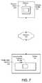
- FIG. 7is a diagram illustrating communication between an exemplary wearable portable electronic device and an exemplary profile web service including at least one customizable gesture profile for the wearable portable electronic device.
- the present inventionrelates to a method and system for gesture-based power management for a wearable portable electronic device with display.
- the following descriptionis presented to enable one of ordinary skill in the art to make and use the invention and is provided in the context of a patent application and its requirements.
- Various modifications to the preferred embodiments and the generic principles and features described hereinwill be readily apparent to those skilled in the art.
- the present inventionis not intended to be limited to the embodiments shown, but is to be accorded the widest scope consistent with the principles and features described herein.
- the exemplary embodiment of the present inventionprovides a method and system for managing power consumption of a wearable portable electronic device (the “portable device”).
- the portable deviceTo make the portable device easy and natural to use, it would be ideal if such a device appeared like a regular mechanical watch, which always presents a clock face, rather than the dark screen of an electronic display that needs to be manually turned on.
- high-resolution color displaysconsume a large amount of power. Leaving these displays on all the time is impractical, as it would quickly drain an already small battery. In fact, the display typically has the highest power consumption of all components in a portable system.
- the exemplary embodimentautomatically turns on the portable device and/or its display when the device is in a viewable orientation without any efforts such as pushing a button or touching the device with the other hand.
- the portable devicemay include a portable data and communications device that is implemented as a modular movement (the “module”) that can be removably inserted within a case of a portable device.
- the portable devicecomprises a watch although the bands are not shown, but the portable device may represent other types of devices, as described below.
- the modulemay be fully-functional standalone and thereby retain functionality after removal from the portable device, but may also be easily user-interchangeable with other portable devices.
- the portable device 10functions as a stand-alone device, without using a module to provide the below-described power management functionality.
- FIGS. 1A-1B and 2are block diagrams illustrating exemplary embodiments of a portable device 10 having a module where like components have like numerals have like reference numerals.
- the module 12includes a body 16 that houses a plurality of layers, including an integrated display 18 (which may be touchscreen) and a movement subassembly 20 , for displaying information, including time.
- FIG. 1Ais a diagram of module 12 shown with a semitransparent body 16 for convenience so that subassembly 20 can be seen through case 16 .
- the term “modular”means that the body 16 of the module 12 includes all parts necessary for operation and power of the module 12 .
- the module 12 of the exemplary embodimentis fully functional in a standalone state.
- the case 14 of the portable device 10includes a receptacle 22 for removably receiving the module 12 without need for a tool, such that the module 12 can be either used with the case 14 of the portable device 10 and/or is user interchangeable with the cases of other electronic devices having the same or similar types of receptacles.
- the body 16may be constructed to provide the module 12 with a degree of water resistance and dust protection.
- the body 16may be a single shell except for an opening for the display 18 and once the display 18 is in place, the display 18 may by sealed with the body 16 using traditional waterproofing methods.
- the body 16may be assembled in separate pieces but then sealed once assembled.
- the module 12 and the receptacle 22 in the case 14are made industry standard sizes, such that different modules 12 manufactured and sold by a one set of manufacturers fit within the receptacles of different cases manufactured and sold by another set of manufacturers, for example.
- FIGS. 1A and 1Bshow an embodiment where the receptacle 22 is formed as an opening in the back of the case 14 and where the top or front of the case 14 includes an opening.
- the module 12is inserted into the case 14 from the bottom or back of the case 14 , and once inserted the display 18 of the module 12 is visible through the opening in the top of the case 14 .
- the display 18 of the module of movement 12becomes the display 18 of the portable device.
- the display 18can include a display assembly including a color LCD display, a glass overlay and a touch overlay.
- the display 18may form the top of the portable device 10 in an exemplary embodiment.
- the display 18can be color, monochrome, black and white, or grayscale.
- the glass in the display 18can be a number of different materials, including glass, tempered glass, quartz, plastic, soda lime glass, white soda lime glass, aluminosilicate, and/or sapphire.
- the glassrepresents some transparent barrier between the outside world and the display area.
- the displayincludes an active viewable area of 25.4 (H) ⁇ 25.4 (V) mm, with a display resolution between approximately 128 (H) ⁇ 128 (V) and 200 (H) ⁇ 200 (W) pixels. Other embodiments include other display resolutions.
- the display 18may also include a wireless antenna for communications with, for example, a Bluetooth headset. In some embodiments the display 18 has an active area that measures less than 2.5′′ diagonally (in other embodiments, less than 2′′ diagonal
- the depth or thicknesses of the module 12 and the case 14may be designed to be substantially similar, so that when the module 12 is inserted, the side of the module 12 facing the open end of the receptacle 22 is coplanar with the back of the case 14 (and the wearer's arm), as shown in FIG. 1A .
- no closureis necessary to seal the case 14 unlike with traditional watches.
- the display 18 of the module 12 that is open through the top of the case 14may be designed to be approximately coplanar with, slightly above, or slightly below, the top of the case 14 .
- the portable device 10may include a combination of both the case 14 and the module 12 .
- the term case 14may denote the body of the portable device 10 into which the receptacle 22 is formed and into which the module 12 is to be inserted.
- the proportionate size of the portable device/case to the receptacle 22is small ( FIGS. 1A and 1B ).
- the size of the portable device/case to the receptacle 22may be larger.
- the module 12is implemented as a computer-based electronic movement that is used to power the portable devices into which it is inserted, as described below.
- FIG. 2is a diagram of an exploded view of the module 12 and components thereof when implemented as a computer-based electronic modular movement according to one exemplary embodiment.
- the module 12includes body 16 that houses multiple layers of components, which in this exemplary embodiment, may include a plastic internal chassis 200 , a rechargeable-type battery 202 , a printed circuit board (PCB) 204 , a touchscreen 206 , and an optional second plastic internal chassis 208 and protective covering 212 .
- the module 12has six sides, but the side with the touchscreen 206 is substantially all display space.
- the PCB 204may include components (described below) such as a memory and processor for executing software that displays a user interface on the touchscreen 206 and that operates the module 12 ; and an optional communications interface for receiving data remotely, which may be displayed and updated on the touchscreen 206 .
- componentssuch as a memory and processor for executing software that displays a user interface on the touchscreen 206 and that operates the module 12 ; and an optional communications interface for receiving data remotely, which may be displayed and updated on the touchscreen 206 .
- Other components of the module 12may include an antenna (not shown) that wraps around the body 16 (alternatively embedded in case 14 ), and a set of contacts 210 inserted into the body 16 and in contact with the PCB.
- the contactsmay be used for recharging the battery (the contacts are both power and ground) and/or for serialized communications.
- the contactscan also be used for orientation purposes for the user to tell which side of the module 12 is up or down when inserting the module 12 into the receptacle 22 of the case 14 .
- the contacts 210are located on a side of the module 12 that is in the receptacle 22 opening so that the portable device 10 as a whole can be placed in a dock and the contacts 210 used to abut the contacts of the dock.
- the contacts 210are located on a side of the module 12 that face inward into the receptacle 22 for abutting with contacts in the receptacle 22 . In yet another embodiment, the contacts 210 may be located on the module 12 such that the contacts 210 wrap around at least two side of the module 12 to be used in both manners.
- the contacts 210are inserted into the body 16 ; and the layers of components are assembled as shown into a movement subassembly 20 .
- the movement subassembly 20is then inserted into the body 16 and the body is sealed, creating the computer-based module 12 .
- FIG. 3is a block diagram illustrating computer components on the PCB comprising the module 12 according to an exemplary embodiment.
- the PCB 504 containing computer 600may be implemented as a single sided or double-sided PCB.
- the PCB 504may be implemented as separate PCBs and stacked within the movement subassembly 514 .
- Computer 600may include components such as processors 602 , memories 604 , inputs/outputs 606 , power manager 608 , a communications interface 610 , and sensors 612 . In one embodiment, one or more of the components of the computer 600 may be implemented on a single chip.
- the processors 602may include at least one microprocessor 614 , a digital signal processor (DSP), a global positioning system (GPS) chip 616 , and a clock 620 .
- DSPdigital signal processor
- GPSglobal positioning system
- Microprocessor 614 and/or DSPmay be capable of concurrently executing multiple software routines, including system code, to control the various processes of the module 12 .
- microprocessor 614may comprise an Advanced RISC Machine (ARM) processor or the like may be used, for example.
- GPS 618may process received satellite signals and with or without microprocessor 614 determine position information such as location, speed, direction, and time.
- Clock 620may be used as an internal timing device for the computer 600 .
- Clock 620which may also be referred to as a real-time clock or system clock, inputs to the microprocessor 614 a constant flow of timing pulses for operation of the microprocessor 614 .
- Clock 620may also keep track of the time of day and makes this data available to the software routines executing in microprocessor 614 .
- clock 620comprises a silicon oscillator clock implemented using micro-electro-mechanical systems (MEMS) technology.
- MEMSmicro-electro-mechanical systems
- clock 620may utilize a quartz crystal oscillator.
- Memories 604may include a random access memory (RAM) 622 and a non-volatile memory 626 .
- RAM 622may be used as the main memory for microprocessor 614 for supporting execution of the software routines and other selective storage functions.
- Non-volatile memory 626is capable of holding instructions and data without power and may store the software routines for controlling module 12 in the form of computer-readable program instructions.
- non-volatile memory 626comprises flash memory.
- non-volatile memory 626may comprise any type of read only memory (ROM).
- the non-volatile memory 626may contain a user interface application 623 , which can provide functionality for the portable device 10 and can output a graphical user interface on the display 18 .
- the non-volatile memory 626can include a gesture store 625 (e.g., a database, or a look-up table), which can contain definitions of different gestures in the form of combinations of sensor inputs, defined here as “gesture rules,” and predetermined functions associated with the gestures that are executed upon identification of the gestures.
- the user interface application 623can access the gesture rules stored in gesture store 625 when movement of the portable device 10 is sensed.
- the predetermined functionmay be executed.
- I/Os 606may include a display controller 630 , an audio chip 632 , and a touchscreen controller 634 .
- Display controller 630may access RAM 622 and transfer processed data, such as time and date and/or a user interface, to the touchscreen 506 for display.
- the audio chip 632is coupled to an optional speaker (not shown) and interfaces with microprocessor 614 to provide audio capability for the module 12 .
- the audio chip 632may be coupled to both a speaker and a microphone (not shown).
- a water resistant/proof speaker and microphonemay be used to retain water resistance of the module 12 .
- the module 12may be implemented without sound capability, in which case no audio chip 632 , speaker or microphone is necessary.
- the microphonemay record voice input that is first processed by the audio chip and then input to the microprocessor 614 for further processing.
- the audio chip 632may include hardware and/or software that converts analog voice into pulse code modulation (PCM) or Adaptive Differential PCM (ADPCM) digital code and vice versa, as well as for compressing and decompressing the PCM or ADPCM digital audio signal.
- PCMpulse code modulation
- ADPCMAdaptive Differential PCM
- the processed voice inputmay be stored for subsequent playback.
- the processed voice inputmay be transferred to communications interface 610 for wireless transmission.
- Touchscreen controller 634may interface with the touchscreen 506 to detect touches and touch locations and pass the information on to microprocessor 614 for determination of user interactions.
- Another example I/O 606may include a USB controller (not shown).
- Power manager 608communicates with the microprocessor 614 and coordinates power management for the computer 600 while the computer is drawing power from the battery 502 during normal operations.
- the battery 502may comprise a rechargeable, lithium ion battery or the like may be used, for example.
- the power manager 608includes a voltage controller 636 and a charging controller 638 for recharging the battery 502 .
- Voltage controller 636may regulate battery voltage to the rest of the computer 600
- charging controller 638may manage appropriate voltage levels to properly charge the battery 502 .
- Power manager 608may further include a microcontroller (not shown) in one embodiment.
- the communications interface 610may include components for supporting one-way or two-way wireless communications.
- the communications interface 610is for primarily receiving data remotely, including streaming data, which is displayed and updated on the touchscreen 506 .
- the communication interface 616could also support voice transmission.
- the communications interface 610supports low and intermediate power radio frequency (RF) communications.
- RFradio frequency
- the communications interface 610may include one or more of a WiFi transceiver 640 for supporting communication with a WiFi network, including wireless local area networks (WLAN), and WiMAX; a cellular transceiver 642 for supporting communication with a cellular network; Bluetooth transceiver 644 for low-power communication according to the Bluetooth protocol and the like, such as wireless personal area networks (WPANs); and passive radio-frequency identification (RFID) 646 .
- WLANwireless local area networks
- RFIDpassive radio-frequency identification
- Others wireless optionsmay include baseband and infrared, for example.
- the communications interface 610may also include other types of communications devices (not shown) besides wireless, such as serial communications via contacts 510 and/or USB communications, for example.
- the sensors 612are representative of devices that can take information about the outside world and supply it to the device 10 .
- the sensors 612can also function with other components to provide user or environmental input and feedback to a user.
- Sensors 612may include at least one of each of an inertial sensor 648 , and any number of optional sensors 1 - n .
- Sensors 612may include at least one of each of an inertial sensor 648 , and any number of optional sensors 1 - n .
- Inertial sensor 648can include a MEMS accelerometer (e.g., a 3-axis accelerometer from ST Microelectronics LIS302DL) that may be used to measure information such as position, motion, tilt, shock, and vibration for use by microprocessor 614 .
- MEMS accelerometere.g., a 3-axis accelerometer from ST Microelectronics LIS302DL
- an inertial sensorincludes a gyroscope to provide information about movement of the portable device 10 .
- An inertial sensor 648 that can trackcan track motion in three dimensions such as those described above may be advantageous because rotational acceleration and absolute deflection may be detected, allowing for more precise tracking of the movement of the portable device 10 .
- the optional sensors 1 - nmay include environmental sensors (e.g., ambient light (e.g., TPS851 from Toshiba), temperature, humidity, pressure (redundant, an altitude sensor is a pressure sensor), magnetic (e.g., Hall Effect), compass, etc), biological sensors (e.g., pulse, blood oxygen saturation, body temperature, blood pressure, body fat, etc.), and a proximity detector for detecting the proximity of objects.
- environmental sensorse.g., ambient light (e.g., TPS851 from Toshiba), temperature, humidity, pressure (redundant, an altitude sensor is a pressure sensor), magnetic (e.g., Hall Effect), compass, etc), biological sensors (e.g., pulse, blood oxygen saturation, body temperature, blood pressure, body fat, etc.), and a proximity detector for detecting the proximity of objects.
- Other examples of sensorsinclude touch screen sensors, haptic sensors, and audio input.
- the touch screencan be capacitance and/or resistance based, or any other touch sensitive device that provides user
- the computer 600may display the information measured from the sensors 612 , analyze the information by microprocessor 614 and display the analyzed information, and/or transmit the raw or analyzed information via the communications interface 610 . In one embodiment, not all of the sensors 612 may be located on PCB 504 .
- the computer 600includes a combination of the inertial sensor 648 , which may be a MEMS accelerometer (or other inertial sensor capable of motion tracking in at least two dimensions such as a gyroscope), the ambient light sensor, and the proximity sensor, such as an infrared reflective sensor.
- the combined information from these sensorsis used to provide feedback required to determine when the display 18 is visible to the user and should be turned on.
- FIG. 4illustrates an exemplary embodiment of a process for gesture-based power management for a wearable portable electronic device.
- the inertial sensor 648is calibrated to a reference orientation that is relative to a user's body angle (block 400 ).
- the user's body anglemay be defined as the angle substantially between the user's torso and the ground.
- the reference orientation for calibrationis shown in FIG. 5 , with the display 18 facing up and the arm in front of the user. While the embodiment shown in FIG. 4 uses the earth's gravity as a reference point, meaning the user's body angle is substantially vertical, for the reference orientation, the reference orientation may utilize different body angles to calibrate the inertial sensor 648 .
- the portable device 10may, with or without a user's request, reset the reference orientation from gravitional (i.e., a substantially vertical body angle) to any other user-selected body angle.
- body anglesmay include a substantially horizontal angle (e.g., when the user is lying substantially on his or her back) and an inclined angle (e.g., when the user is reclined in a chair or seat in a car or airplane).
- FIG. 5shows the 3 reference axes, x, y and z, which form a reference coordinate system.
- the x-axisruns parallel to and in front of the body.
- the y-axisgoes through the body (axis from chest to device).
- the z-axisruns up and down (from device to the ceiling).
- FIG. 5also shows rotational angles a, b, and c, around each axis. Utilizing three-dimensional sensing may be advantageous over electronic devices using fewer sensing axes because angles and positions that a user would use to view the display 18 of the portable device 10 can be more precisely sensed. This can lead to more efficient battery use because the display 18 may not be turned on when the portable device 10 is in an angle and/or position that is excluded.
- the inertial sensortracks motion of the portable device 10 with respect to this reference orientation (block 402 ).
- the display 18is enabled when the device 10 is within a viewable range, where the viewable range is a predefined rotational angle range in each of the x, y, and z axis, to a user based upon a position of the device 10 with respect to the reference orientation (block 404 ). Enabling the display 18 can take the form of turning on the display 18 so that the user may interact with the user interface application 623 .
- the following rotational angle rangesin exemplary embodiments, define the spatial positions where the display is viewable when worn on either wrist:
- the device 10must be within all three angle ranges in order for the display 18 to be on.
- these predefined rotational angle rangescan be reconfigured by the user. Additionally, the predefined rotational angle ranges may include different angle ranges corresponding to different wear locations on the body, such as a pendant of a necklace.
- the inertial sensor 648provides information in the (x,y,z) coordinates, thereby allowing a standard mathematical translation of the viewable angle ranges to (x,y,z) coordinates to be calculated.
- the microprocessor 614can track the current (x,y,z) position and actively determine whether the device is within the viewable range.
- the portable device 10may detect the user's body angle.
- the viewable rangemay then be determined based upon the user's body angle. For example, if the portable device 10 detects that the user's body angle is not substantially vertical (e.g., the user is lying on his or her back, or is sitting in a reclined position), the reference orientation and the viewable range can be automatically adjusted by the difference between the user's body angle and a vertical body angle.
- the usermay customize the viewable range when the user is in a different body angle, and store the customized viewable range so that the customized viewable range may be used when the portable device 10 detects that the user has entered the corresponding body angle.
- the device display 18should be turned-off.
- the display 18is turned off if an object is detected within a predetermined distance of the surface of the display 18 for a predetermined amount of time.
- the predetermined distance and the predetermined amount of timeare user configurable.
- the proximity sensorcan be configured to detect objects within a certain proximity of the display, such as one inch, two inches, 0.5 inches, 1 millimeter, etc.
- the proximity sensordetects an object for a configurable amount of fixed time, such as 10 seconds, before turning off the display.
- the objectmay be detected by a plurality of proximity sensors located on an edge or edges of the display 18 .
- a plurality of proximity sensorslocated on an edge or edges of the display 18 .
- an embodimentmight use two or more proximity sensors, one on each opposite corner of the display 18 . This would further ensure the entire display was being covered vs. some partial covering of fingers that might occur during normal use.
- the displayshould instantly turn back on, assuming that the display is within an allowable visible angle range.
- a logical formuladescribes the algorithm that determines whether the display is ON:
- the ambient light sensorcan provide the information that determines display brightness.
- Most electronic display componentsprovide analog brightness control, and the display controller 630 or microprocessor 614 can set the maximum brightness to different levels, depending the reading from the light sensor. This, in itself, is a common technique used on many portable devices, but when used in combination with the other sensors, provides a more effective and adaptive method for managing display power.
- the devicealso contains a location detection element (such as a GPS chip).
- a location detection elementsuch as a GPS chip.
- the processorcould compute whether it is day or night. This data can be used to determine the maximum amount of ambient light available, and therefore set a minimum threshold for the display brightness.
- Another further optimizationinvolves determining when the portable device 10 will not be viewed by a user, such as when the portable device 10 is not being worn, or when the display 18 is facing the ground.
- an additional sensorsuch as a skin temperature sensor, capacitance sensor, or electrodes, can be used. If it is being worn, the algorithm described above provides the display control. If it is not worn, the display may be turned off and only turned on by an active user command, such as touching the touchscreen display or pushing a button.
- the inertial sensor 648may be used to determine if the display 18 is facing the ground (e.g., if the display 18 is parallel to and facing gravitational force) for a predetermined amount of time. If the display is facing the ground for the predetermined amount of time, then the display may be turned off and only turned on by an active user command.
- the usermay enable a “locked mode” for the portable device 10 , wherein the display is not enabled even when the user enters a viewable range, by inputting a lock device command.
- the locked modecan be advantageous, for example, when the user is in a movie theater or asleep, and the lighting of the display would be undesirable.
- the locked modecan be maintained until the user repeats the lock device command in an exemplary embodiment.
- the portable device 10may have multiple sensors to provide an abundance of data on the device's orientation and environment. Each additional sensor may provide additional information that allows the algorithm to rule in or out a certain condition, further enabling the device to intelligently discriminate between two similar motions with very different intents.
- a user's motion to turn the steering wheel of a carresults in the wrist being in an orientation that falls within the ranges described above.
- the deviceonly contains a single inertial sensor 648 , it may be difficult for the algorithm to discriminate between the motions of looking at the watch versus steering a car. A user might become annoyed if the display 18 blinks on and off as he steers a car.
- the algorithmcan examine both the inertial sensor 648 data and data from a complementary sensor, such as an ambient light sensor, a more accurate assessment can be made. For instance, there are typically many shadow regions inside a car due to the presence of the door, the roof, dashboard lights, etc. The wrist of a user turning a steering wheel would pass through several regions of different light intensity during wrist motion.
- the ambient light data combined with the inertial datamay be used to determine that the user only intended to turn the steering wheel of a car and did not actually want to look at the watch face, thereby preventing the display 18 from turning on unnecessarily.
- the algorithmmay employ the techniques of Bayesian inference (a common method known to computer programmers) in order to learn the behavioral patterns of an individual user and therefore make increasingly accurate determinations that the user is truly looking at his watch instead of performing some other gesture.
- the device 10may collect and store sensor information that the algorithm will employ to improve its ability, over time, to correctly interpret gestures.
- Bayesian analysiscan be triggered, for example, by detecting that a user enters a “learning mode,” wherein the user indicates to the portable device 10 when the user is looking at the display 18 of the portable device 10 .
- the usermay indicate that the user is looking at the display 18 by using a predetermined indication, which can be any suitable command recognized by the portable device (e.g., three taps on the side of the portable device 10 , etc.).
- a predetermined indicationcan be any suitable command recognized by the portable device (e.g., three taps on the side of the portable device 10 , etc.).
- Bayesian analysiscan be used, in an exemplary embodiment, to change (e.g., shift the range, narrow the range, or broaden the range) the viewable range after receiving at least one predetermined indication. This can be particularly advantageous when the user uses the portable device 10 during activities, such as running, swimming, or riding a bicycle, for example.
- one embodimentcould gradually ramp up and/or ramp down the display brightness at the edges of the viewable angle ranges. That is, the display brightness may be gradually increased when entering the predetermined rotational angle ranges and gradually reduced when exiting the predetermined rotational angle ranges.
- the display 18could start turning on, and as the angle a increases to ⁇ 15, the display gradually turns on, finally reaching full brightness at ⁇ 20 degrees.
- the displaywould also gradually turn off as the angle moved from ⁇ 20 to ⁇ 30 degrees in the opposite motion. Extending this to three dimensions, the device 10 display would appear to gradually turn on and off as the device moved through various viewable ranges.
- At least one component of the portable device 10can be selectively turned off in different operation modes.
- An operation modemay be a power management profile stored on the portable device 10 that may contain customized settings for power management and may be selectively activated by the user.
- the processors 602or a micro-controller
- the communications interface 610 and/or the GPS 618can be disabled to save power.
- the usermay desire to have the display 18 and the communications interface 610 off when exercise is being done, but may customize the power management in an exercise operation mode to allow the GPS 618 to be on, so that the user can keep track of his or her distance traveled.
- FIG. 6is a diagram illustrating exemplary types of portable device form factors that could be used with module 12 and receptacle 22 and the power management scheme of the exemplary embodiment.
- exemplary types of portable devicesthat may include standard receptacles 22 for use with module 12 may include a cell phone handset 700 , a carrier and strap 702 , a media player 704 , portable speakers 706 , battery dock recharger and speaker 708 , a watch 710 , a media handset and cradle 712 , a telephone handset 714 , and a portable charging cradle 716 for the module 12 .
- the module 12can be recharged, even while outside of the portable device 10 .
- the exemplary embodimentprovides a module movement 12 that can be used, operated and recharged whether both alone and when inserted into the portable device 10 .
- portable devicesinclude a bike handlebar cradle, a modem housing (e.g., for notebook computers), an adapter to convert to a USB dongle, jewelry, a lanyard, clothing, a keychain and a necklace, for instance.
- FIG. 7is a diagram illustrating communication between an exemplary portable device 10 and an exemplary profile web service 726 including at least one customizable gesture profile 728 for the portable device 10 .
- the gesture store 625 of the portable device 10may include at least one gesture profile.
- a gesture profilemay include definitions for different gestures that can provide input for the portable device 10 .
- Display profile 720is an example of a gesture profile, and may include default power management settings of the display, such as the viewable angle ranges and/or proximity sensor settings, for example.
- the portable device 10can be in communication with a server 724 , which may include a profile web service 726 , through a network 722 .
- the profile web service 726may include customizable gesture profile 728 , which may contain, for example, modified settings for the display profile 720 .
- the customizable gesture profile 728may differ from the display profile 720 in that the customizable gesture profile 728 may include viewable angle ranges that are adjusted to take into account viewable angle parameters such as, for example, different user heights, arm lengths, locations, and/or time zones.
- the customizable gesture profile 728may include one or more operation modes for the portable device 10 .
- the usermay select a customizable gesture profile 728 from a plurality of precreated stored profiles on the profile web service 726 .
- the usermay enter his or her personal information relating to one or more of the viewable angle parameters, and a customizable gesture profile 728 may be generated based upon the entered viewable angle parameters.
- a customizable gesture profile 728 of interestthe user may download the customizable gesture profile 728 to the portable device 10 , thereby adjusting the power management settings of the portable device 10 .
- the customizable gesture profile 728may exist separately from the display profile 720 or it may overwrite the settings within the display profile 720 in the non-volatile memory 626 of the portable device 10 .
- a gesture-based power management method and system for a portable device with displayhas been disclosed.
- the present inventionhas been described in accordance with the embodiments shown, and one of ordinary skill in the art will readily recognize that there could be variations to the embodiments, and any variations would be within the spirit and scope of the present invention.
- the portable devicemay be provided without communication capability and used to store a user's personal information, such as medical records for, instance.
- the embodimentscan be implemented using hardware, software, a computer readable medium containing program instructions, or a combination thereof.
- Software written according to the present inventionis to be either stored in some form of computer-readable medium such as memory and is to be executed by a processor. Accordingly, many modifications may be made by one of ordinary skill in the art without departing from the spirit and scope of the appended claims.
Landscapes
- Engineering & Computer Science (AREA)
- Theoretical Computer Science (AREA)
- General Engineering & Computer Science (AREA)
- Physics & Mathematics (AREA)
- General Physics & Mathematics (AREA)
- Human Computer Interaction (AREA)
- User Interface Of Digital Computer (AREA)
Abstract
Description
| Viewable Ranges | ||
| Display Angle | On Left Wrist | On Right Wrist | |
| a | rotation on x axis | −30 to +180 deg | −30 to +180 deg |
| b | rotation on y axis | −45 to +45 deg | −45 to +45 deg |
| c | rotation on z axis | −180 to +90 deg | −90 to +180 deg |
- V=display is in allowable visible range for a, b, and c
- P=proximity detector does not detect any objects for longer than the programmed fixed time
- ON=V AND P
Claims (28)
Priority Applications (1)
| Application Number | Priority Date | Filing Date | Title |
|---|---|---|---|
| US12/356,457US8344998B2 (en) | 2008-02-01 | 2009-01-20 | Gesture-based power management of a wearable portable electronic device with display |
Applications Claiming Priority (2)
| Application Number | Priority Date | Filing Date | Title |
|---|---|---|---|
| US2570308P | 2008-02-01 | 2008-02-01 | |
| US12/356,457US8344998B2 (en) | 2008-02-01 | 2009-01-20 | Gesture-based power management of a wearable portable electronic device with display |
Publications (2)
| Publication Number | Publication Date |
|---|---|
| US20090195497A1 US20090195497A1 (en) | 2009-08-06 |
| US8344998B2true US8344998B2 (en) | 2013-01-01 |
Family
ID=40931185
Family Applications (1)
| Application Number | Title | Priority Date | Filing Date |
|---|---|---|---|
| US12/356,457Expired - Fee RelatedUS8344998B2 (en) | 2008-02-01 | 2009-01-20 | Gesture-based power management of a wearable portable electronic device with display |
Country Status (1)
| Country | Link |
|---|---|
| US (1) | US8344998B2 (en) |
Cited By (32)
| Publication number | Priority date | Publication date | Assignee | Title |
|---|---|---|---|---|
| US20090079701A1 (en)* | 2007-09-25 | 2009-03-26 | Grosskopf Jr George | Device and Method for Displaying Data and Receiving User Input |
| US8856948B1 (en) | 2013-12-23 | 2014-10-07 | Google Inc. | Displaying private information on personal devices |
| US8976063B1 (en) | 2014-04-29 | 2015-03-10 | Google Inc. | Automated detection of vehicle parking and location |
| US9009516B1 (en) | 2014-02-19 | 2015-04-14 | Google Inc. | Adjusting a power mode of a wearable computing device based on motion data |
| US9037199B1 (en)* | 2014-02-13 | 2015-05-19 | Google Inc. | Detecting transitions between physical activity |
| US9042596B2 (en) | 2012-06-14 | 2015-05-26 | Medibotics Llc | Willpower watch (TM)—a wearable food consumption monitor |
| CN104714625A (en)* | 2013-12-11 | 2015-06-17 | 联想(北京)有限公司 | Information processing method and electronic device |
| US20150261315A1 (en)* | 2014-03-11 | 2015-09-17 | Google Technology Holdings LLC | Display viewing detection |
| US20150286391A1 (en)* | 2014-04-08 | 2015-10-08 | Olio Devices, Inc. | System and method for smart watch navigation |
| US9159294B2 (en) | 2014-01-31 | 2015-10-13 | Google Inc. | Buttonless display activation |
| US9254099B2 (en) | 2013-05-23 | 2016-02-09 | Medibotics Llc | Smart watch and food-imaging member for monitoring food consumption |
| US9442100B2 (en) | 2013-12-18 | 2016-09-13 | Medibotics Llc | Caloric intake measuring system using spectroscopic and 3D imaging analysis |
| US9442570B2 (en) | 2013-03-13 | 2016-09-13 | Google Technology Holdings LLC | Method and system for gesture recognition |
| US9497309B2 (en) | 2011-02-21 | 2016-11-15 | Google Technology Holdings LLC | Wireless devices and methods of operating wireless devices based on the presence of another person |
| US9529385B2 (en) | 2013-05-23 | 2016-12-27 | Medibotics Llc | Smart watch and human-to-computer interface for monitoring food consumption |
| US9536449B2 (en) | 2013-05-23 | 2017-01-03 | Medibotics Llc | Smart watch and food utensil for monitoring food consumption |
| US20170068327A1 (en)* | 2013-11-08 | 2017-03-09 | Polar Electro Oy | User interface control in portable system |
| US9804679B2 (en) | 2015-07-03 | 2017-10-31 | Google Inc. | Touchless user interface navigation using gestures |
| US9832187B2 (en) | 2014-01-07 | 2017-11-28 | Google Llc | Managing display of private information |
| US9942384B2 (en) | 2013-09-10 | 2018-04-10 | Google Technology Holdings LLC | Method and apparatus for device mode detection |
| US9996109B2 (en) | 2014-08-16 | 2018-06-12 | Google Llc | Identifying gestures using motion data |
| US10095186B2 (en) | 2016-09-14 | 2018-10-09 | Nxp B.V. | User interface activation |
| US10118696B1 (en) | 2016-03-31 | 2018-11-06 | Steven M. Hoffberg | Steerable rotating projectile |
| US10119864B2 (en) | 2014-03-11 | 2018-11-06 | Google Technology Holdings LLC | Display viewing detection |
| US10169559B2 (en) | 2014-02-21 | 2019-01-01 | Samsung Electronics Co., Ltd. | Controlling input/output devices |
| US10311249B2 (en) | 2017-03-31 | 2019-06-04 | Google Llc | Selectively obscuring private information based on contextual information |
| US10314492B2 (en) | 2013-05-23 | 2019-06-11 | Medibotics Llc | Wearable spectroscopic sensor to measure food consumption based on interaction between light and the human body |
| US10374804B2 (en) | 2014-09-11 | 2019-08-06 | Samsung Electronics Co., Ltd. | Method of controlling electronic device using wearable device and method of operating electronic device |
| US10660039B1 (en) | 2014-09-02 | 2020-05-19 | Google Llc | Adaptive output of indications of notification data |
| USRE48447E1 (en)* | 2013-10-04 | 2021-02-23 | Panasonic Intellectual Property Corporation Of America | Wearable terminal and method for controlling the same |
| US11320889B2 (en) | 2015-11-20 | 2022-05-03 | Samsung Electronics Co., Ltd. | Function operating method and electronic apparatus supporting same |
| US11712637B1 (en) | 2018-03-23 | 2023-08-01 | Steven M. Hoffberg | Steerable disk or ball |
Families Citing this family (185)
| Publication number | Priority date | Publication date | Assignee | Title |
|---|---|---|---|---|
| GB2465848A (en)* | 2008-12-08 | 2010-06-09 | Rotary Watches Ltd | Digital wristwatch with touchscreen |
| US8289162B2 (en)* | 2008-12-22 | 2012-10-16 | Wimm Labs, Inc. | Gesture-based user interface for a wearable portable device |
| KR101545876B1 (en)* | 2009-01-22 | 2015-08-27 | 삼성전자주식회사 | Method for reducing power consumption based on motion sensor and portable terminal using the same |
| US20110054775A1 (en)* | 2009-08-25 | 2011-03-03 | Thomas David Snyder | Electronic device with gps application triggered display |
| KR20110041110A (en)* | 2009-10-15 | 2011-04-21 | 삼성전자주식회사 | Method and device for managing touch function in portable terminal |
| US9174123B2 (en) | 2009-11-09 | 2015-11-03 | Invensense, Inc. | Handheld computer systems and techniques for character and command recognition related to human movements |
| WO2011059404A2 (en)* | 2009-11-12 | 2011-05-19 | Nanyang Polytechnic | Method and system for interactive gesture-based control |
| US8332181B1 (en)* | 2009-12-09 | 2012-12-11 | The Boeing Company | System and method for alignment using a portable inertial device |
| EP2357220A1 (en)* | 2010-02-10 | 2011-08-17 | The Procter & Gamble Company | Cleaning composition comprising amylase variants with high stability in the presence of a chelating agent |
| US8452463B2 (en)* | 2010-06-04 | 2013-05-28 | Apple Inc. | Adjusting the thermal behavior of a computing system using indirect information about ambient temperature |
| US8768530B2 (en) | 2010-06-04 | 2014-07-01 | Apple Inc. | Thermal zone monitoring in an electronic device |
| US9310909B2 (en) | 2010-09-30 | 2016-04-12 | Fitbit, Inc. | Methods, systems and devices for physical contact activated display and navigation |
| WO2012052069A1 (en)* | 2010-10-22 | 2012-04-26 | Sony Ericsson Mobile Communications Ab | Mobile communication device with three-dimensional sensing and a method therefore |
| KR20140130740A (en)* | 2010-12-13 | 2014-11-11 | 엠파이어 테크놀로지 디벨롭먼트 엘엘씨 | Disabling an automatic rotation function of mobile computing devices |
| US10244988B2 (en)* | 2010-12-16 | 2019-04-02 | Nokia Technologies Oy | Method, apparatus and computer program of using a bio-signal profile |
| US8766912B2 (en) | 2010-12-29 | 2014-07-01 | Empire Technology Development Llc | Environment-dependent dynamic range control for gesture recognition |
| KR20120079245A (en)* | 2011-01-04 | 2012-07-12 | 엘지전자 주식회사 | Control method for air conditioning apparatus |
| US9201185B2 (en) | 2011-02-04 | 2015-12-01 | Microsoft Technology Licensing, Llc | Directional backlighting for display panels |
| CN102707860A (en)* | 2011-03-28 | 2012-10-03 | 鸿富锦精密工业(深圳)有限公司 | Screen saver control system and method |
| US9436231B2 (en) | 2011-04-07 | 2016-09-06 | Qualcomm Incorporated | Rest detection using accelerometer |
| US9078070B2 (en) | 2011-05-24 | 2015-07-07 | Analog Devices, Inc. | Hearing instrument controller |
| US20140206289A1 (en)* | 2011-06-10 | 2014-07-24 | Aliphcom | Data-capable band management in an integrated application and network communication data environment |
| US8823520B2 (en)* | 2011-06-16 | 2014-09-02 | The Boeing Company | Reconfigurable network enabled plug and play multifunctional processing and sensing node |
| US8903656B2 (en)* | 2011-07-05 | 2014-12-02 | Innovmetric Logiciels Inc. | Synchronization of the position and orientation of a 3D measurement device and the position and orientation of an intelligent guidance device |
| US8199126B1 (en)* | 2011-07-18 | 2012-06-12 | Google Inc. | Use of potential-touch detection to improve responsiveness of devices |
| US20130033418A1 (en)* | 2011-08-05 | 2013-02-07 | Qualcomm Incorporated | Gesture detection using proximity or light sensors |
| US9002322B2 (en) | 2011-09-29 | 2015-04-07 | Apple Inc. | Authentication with secondary approver |
| EP2579127A1 (en)* | 2011-10-04 | 2013-04-10 | Research In Motion Limited | Orientation determination for a mobile device |
| US9804678B2 (en)* | 2011-10-18 | 2017-10-31 | Slyde Watch Sa | Method and circuit for switching a wristwatch from a first power mode to a second power mode |
| US20130151722A1 (en)* | 2011-12-13 | 2013-06-13 | Motorola Mobility, Inc. | Method and Apparatus for Utilizing Streaming Content at an Electronic Device |
| CN104246668B (en)* | 2012-01-10 | 2017-03-22 | 马克西姆综合产品公司 | Method and apparatus for activating electronic devices with gestures |
| US9354748B2 (en) | 2012-02-13 | 2016-05-31 | Microsoft Technology Licensing, Llc | Optical stylus interaction |
| US9423877B2 (en)* | 2012-02-24 | 2016-08-23 | Amazon Technologies, Inc. | Navigation approaches for multi-dimensional input |
| US9064654B2 (en) | 2012-03-02 | 2015-06-23 | Microsoft Technology Licensing, Llc | Method of manufacturing an input device |
| US9460029B2 (en) | 2012-03-02 | 2016-10-04 | Microsoft Technology Licensing, Llc | Pressure sensitive keys |
| US8873227B2 (en) | 2012-03-02 | 2014-10-28 | Microsoft Corporation | Flexible hinge support layer |
| US9360893B2 (en) | 2012-03-02 | 2016-06-07 | Microsoft Technology Licensing, Llc | Input device writing surface |
| US9870066B2 (en) | 2012-03-02 | 2018-01-16 | Microsoft Technology Licensing, Llc | Method of manufacturing an input device |
| USRE48963E1 (en) | 2012-03-02 | 2022-03-08 | Microsoft Technology Licensing, Llc | Connection device for computing devices |
| US9298236B2 (en) | 2012-03-02 | 2016-03-29 | Microsoft Technology Licensing, Llc | Multi-stage power adapter configured to provide a first power level upon initial connection of the power adapter to the host device and a second power level thereafter upon notification from the host device to the power adapter |
| US9075566B2 (en) | 2012-03-02 | 2015-07-07 | Microsoft Technoogy Licensing, LLC | Flexible hinge spine |
| US9426905B2 (en) | 2012-03-02 | 2016-08-23 | Microsoft Technology Licensing, Llc | Connection device for computing devices |
| US9116545B1 (en) | 2012-03-21 | 2015-08-25 | Hayes Solos Raffle | Input detection |
| US8898496B1 (en) | 2012-03-23 | 2014-11-25 | Google Inc. | Context-based power management |
| US9201512B1 (en) | 2012-04-02 | 2015-12-01 | Google Inc. | Proximity sensing for input detection |
| US9128522B2 (en) | 2012-04-02 | 2015-09-08 | Google Inc. | Wink gesture input for a head-mountable device |
| US20130271355A1 (en) | 2012-04-13 | 2013-10-17 | Nokia Corporation | Multi-segment wearable accessory |
| US9746916B2 (en) | 2012-05-11 | 2017-08-29 | Qualcomm Incorporated | Audio user interaction recognition and application interface |
| US9736604B2 (en) | 2012-05-11 | 2017-08-15 | Qualcomm Incorporated | Audio user interaction recognition and context refinement |
| US20130300590A1 (en) | 2012-05-14 | 2013-11-14 | Paul Henry Dietz | Audio Feedback |
| US9459737B2 (en)* | 2012-05-23 | 2016-10-04 | Atmel Corporation | Proximity detection using multiple inputs |
| US10031556B2 (en) | 2012-06-08 | 2018-07-24 | Microsoft Technology Licensing, Llc | User experience adaptation |
| US9019615B2 (en) | 2012-06-12 | 2015-04-28 | Microsoft Technology Licensing, Llc | Wide field-of-view virtual image projector |
| US8947353B2 (en) | 2012-06-12 | 2015-02-03 | Microsoft Corporation | Photosensor array gesture detection |
| US9684382B2 (en) | 2012-06-13 | 2017-06-20 | Microsoft Technology Licensing, Llc | Input device configuration having capacitive and pressure sensors |
| US9459160B2 (en) | 2012-06-13 | 2016-10-04 | Microsoft Technology Licensing, Llc | Input device sensor configuration |
| US9256089B2 (en) | 2012-06-15 | 2016-02-09 | Microsoft Technology Licensing, Llc | Object-detecting backlight unit |
| US20140180595A1 (en)* | 2012-12-26 | 2014-06-26 | Fitbit, Inc. | Device state dependent user interface management |
| US9710073B2 (en)* | 2012-08-14 | 2017-07-18 | Oleksiy Bragin | Detachable device case having an auxiliary touch input device and data handling capability |
| US8964379B2 (en) | 2012-08-20 | 2015-02-24 | Microsoft Corporation | Switchable magnetic lock |
| EP2703946B1 (en)* | 2012-08-28 | 2016-10-05 | Samsung Electronics Co., Ltd | Low power detection apparatus and method |
| JP5590511B2 (en)* | 2012-09-19 | 2014-09-17 | カシオ計算機株式会社 | FUNCTION DRIVE DEVICE, FUNCTION DRIVE METHOD, AND FUNCTION DRIVE PROGRAM |
| US9268136B1 (en) | 2012-09-28 | 2016-02-23 | Google Inc. | Use of comparative sensor data to determine orientation of head relative to body |
| US8654030B1 (en) | 2012-10-16 | 2014-02-18 | Microsoft Corporation | Antenna placement |
| EP2908970B1 (en) | 2012-10-17 | 2018-01-03 | Microsoft Technology Licensing, LLC | Metal alloy injection molding protrusions |
| US8786767B2 (en) | 2012-11-02 | 2014-07-22 | Microsoft Corporation | Rapid synchronized lighting and shuttering |
| CN103001659B (en)* | 2012-12-03 | 2016-02-10 | 惠州Tcl移动通信有限公司 | A kind of kit with radio communication function for mobile terminal |
| TW201423367A (en)* | 2012-12-14 | 2014-06-16 | Hon Hai Prec Ind Co Ltd | Electronic device and power saving method thereof |
| KR102049475B1 (en)* | 2013-01-08 | 2020-01-08 | 삼성전자주식회사 | Input device, display device and methods of controlling thereof |
| US20140197963A1 (en) | 2013-01-15 | 2014-07-17 | Fitbit, Inc. | Portable monitoring devices and methods of operating the same |
| US9606635B2 (en)* | 2013-02-15 | 2017-03-28 | Microsoft Technology Licensing, Llc | Interactive badge |
| US10578499B2 (en) | 2013-02-17 | 2020-03-03 | Microsoft Technology Licensing, Llc | Piezo-actuated virtual buttons for touch surfaces |
| US9674707B2 (en)* | 2013-03-15 | 2017-06-06 | Apple Inc. | Facilitating a secure session between paired devices |
| WO2014143776A2 (en) | 2013-03-15 | 2014-09-18 | Bodhi Technology Ventures Llc | Providing remote interactions with host device using a wireless device |
| US9304549B2 (en) | 2013-03-28 | 2016-04-05 | Microsoft Technology Licensing, Llc | Hinge mechanism for rotatable component attachment |
| US9552777B2 (en) | 2013-05-10 | 2017-01-24 | Microsoft Technology Licensing, Llc | Phase control backlight |
| US9996117B2 (en)* | 2013-06-07 | 2018-06-12 | Insyde Software Corp. | Touch device and method for controlling the same to perform a power-saving function or a power-on function |
| WO2014201642A1 (en)* | 2013-06-19 | 2014-12-24 | 东莞宇龙通信科技有限公司 | Smart watch and display method for smart watch |
| US9342671B2 (en) | 2013-07-01 | 2016-05-17 | Blackberry Limited | Password by touch-less gesture |
| US9323336B2 (en) | 2013-07-01 | 2016-04-26 | Blackberry Limited | Gesture detection using ambient light sensors |
| US9489051B2 (en) | 2013-07-01 | 2016-11-08 | Blackberry Limited | Display navigation using touch-less gestures |
| US9398221B2 (en) | 2013-07-01 | 2016-07-19 | Blackberry Limited | Camera control using ambient light sensors |
| US9423913B2 (en) | 2013-07-01 | 2016-08-23 | Blackberry Limited | Performance control of ambient light sensors |
| US9367137B2 (en) | 2013-07-01 | 2016-06-14 | Blackberry Limited | Alarm operation by touch-less gesture |
| US9256290B2 (en) | 2013-07-01 | 2016-02-09 | Blackberry Limited | Gesture detection using ambient light sensors |
| US9405461B2 (en) | 2013-07-09 | 2016-08-02 | Blackberry Limited | Operating a device using touchless and touchscreen gestures |
| KR102179812B1 (en)* | 2013-07-18 | 2020-11-17 | 엘지전자 주식회사 | Watch type mobile terminal |
| US9645721B2 (en)* | 2013-07-19 | 2017-05-09 | Apple Inc. | Device input modes with corresponding cover configurations |
| US9304596B2 (en) | 2013-07-24 | 2016-04-05 | Blackberry Limited | Backlight for touchless gesture detection |
| US9465448B2 (en) | 2013-07-24 | 2016-10-11 | Blackberry Limited | Backlight for touchless gesture detection |
| US11921471B2 (en) | 2013-08-16 | 2024-03-05 | Meta Platforms Technologies, Llc | Systems, articles, and methods for wearable devices having secondary power sources in links of a band for providing secondary power in addition to a primary power source |
| US10188309B2 (en) | 2013-11-27 | 2019-01-29 | North Inc. | Systems, articles, and methods for electromyography sensors |
| US20150124566A1 (en) | 2013-10-04 | 2015-05-07 | Thalmic Labs Inc. | Systems, articles and methods for wearable electronic devices employing contact sensors |
| US9194741B2 (en) | 2013-09-06 | 2015-11-24 | Blackberry Limited | Device having light intensity measurement in presence of shadows |
| KR20150030455A (en)* | 2013-09-12 | 2015-03-20 | (주)스피치이노베이션컨설팅그룹 | A Portable Device and A Method for Controlling the Same |
| US20150092520A1 (en)* | 2013-09-27 | 2015-04-02 | Google Inc. | Adaptive Trigger Point For Smartwatch Gesture-to-Wake |
| US8944958B1 (en) | 2013-10-02 | 2015-02-03 | Fitbit, Inc. | Biometric sensing device having adaptive data threshold and a performance goal |
| US9241360B2 (en) | 2013-11-22 | 2016-01-19 | Brian Mullin Friedman | Systems, apparatus, and methods for programmatically associating nearby users |
| US9971412B2 (en)* | 2013-12-20 | 2018-05-15 | Lenovo (Singapore) Pte. Ltd. | Enabling device features according to gesture input |
| US9383818B2 (en)* | 2013-12-27 | 2016-07-05 | Google Technology Holdings LLC | Method and system for tilt-based actuation |
| CN103713740A (en)* | 2013-12-31 | 2014-04-09 | 华为技术有限公司 | Wrist-wearing-type terminal device and display control method thereof |
| US9448631B2 (en) | 2013-12-31 | 2016-09-20 | Microsoft Technology Licensing, Llc | Input device haptics and pressure sensing |
| US9317072B2 (en) | 2014-01-28 | 2016-04-19 | Microsoft Technology Licensing, Llc | Hinge mechanism with preset positions |
| US9542844B2 (en)* | 2014-02-11 | 2017-01-10 | Google Inc. | Providing navigation directions in view of device orientation relative to user |
| US9218034B2 (en)* | 2014-02-13 | 2015-12-22 | Qualcomm Incorporated | User-directed motion gesture control |
| US9759854B2 (en) | 2014-02-17 | 2017-09-12 | Microsoft Technology Licensing, Llc | Input device outer layer and backlighting |
| US11990019B2 (en) | 2014-02-27 | 2024-05-21 | Fitbit, Inc. | Notifications on a user device based on activity detected by an activity monitoring device |
| US9031812B2 (en) | 2014-02-27 | 2015-05-12 | Fitbit, Inc. | Notifications on a user device based on activity detected by an activity monitoring device |
| EP2913738A1 (en)* | 2014-02-27 | 2015-09-02 | Nokia Technologies OY | Performance of an operation based at least in part on tilt of a wrist worn apparatus |
| US10120420B2 (en) | 2014-03-21 | 2018-11-06 | Microsoft Technology Licensing, Llc | Lockable display and techniques enabling use of lockable displays |
| DE102014104131A1 (en)* | 2014-03-25 | 2015-10-01 | Msa Europe Gmbh | Monitoring device and monitoring system |
| US9183709B2 (en)* | 2014-03-26 | 2015-11-10 | Intel Corporation | Wearable device as an ambient information display |
| WO2015149852A1 (en)* | 2014-04-03 | 2015-10-08 | Vertu Corporation Limited | Antenna radiator integrated to touch sensitive device for mobile apparatus |
| KR102248845B1 (en)* | 2014-04-16 | 2021-05-06 | 삼성전자주식회사 | Wearable device, master device operating with the wearable device, and control method for wearable device |
| US10313506B2 (en) | 2014-05-30 | 2019-06-04 | Apple Inc. | Wellness aggregator |
| US9967401B2 (en) | 2014-05-30 | 2018-05-08 | Apple Inc. | User interface for phone call routing among devices |
| EP3108342B1 (en) | 2014-05-30 | 2019-10-23 | Apple Inc. | Transition from use of one device to another |
| CN104063092B (en)* | 2014-06-16 | 2016-12-07 | 青岛歌尔声学科技有限公司 | A kind of touch screen control method and device |
| KR20160004770A (en) | 2014-07-04 | 2016-01-13 | 엘지전자 주식회사 | Watch-type mobile terminal |
| MX2014008351A (en)* | 2014-07-08 | 2016-01-07 | Digital Experiences S A P I De C V | Method and device for the administration of the energy consumption of a portable electronic device activated by gestures or movements. |
| US20160018899A1 (en) | 2014-07-18 | 2016-01-21 | Apple Inc. | Detecting loss of user focus in a device |
| TWI647608B (en) | 2014-07-21 | 2019-01-11 | 美商蘋果公司 | Remote user interface |
| US10324733B2 (en) | 2014-07-30 | 2019-06-18 | Microsoft Technology Licensing, Llc | Shutdown notifications |
| US10339293B2 (en) | 2014-08-15 | 2019-07-02 | Apple Inc. | Authenticated device used to unlock another device |
| WO2016036603A1 (en) | 2014-09-02 | 2016-03-10 | Apple Inc. | Reduced size configuration interface |
| US9424048B2 (en) | 2014-09-15 | 2016-08-23 | Microsoft Technology Licensing, Llc | Inductive peripheral retention device |
| US9952675B2 (en) | 2014-09-23 | 2018-04-24 | Fitbit, Inc. | Methods, systems, and apparatuses to display visibility changes responsive to user gestures |
| US9447620B2 (en) | 2014-09-30 | 2016-09-20 | Microsoft Technology Licensing, Llc | Hinge mechanism with multiple preset positions |
| CN104363333B (en)* | 2014-10-23 | 2017-06-06 | 上海卓易科技股份有限公司 | A kind of intelligent go out screen method, terminal and system |
| GB2531718B (en) | 2014-10-24 | 2017-08-02 | Cambridge temperature concepts ltd | Activating an electronic device |
| US9459698B2 (en)* | 2014-12-10 | 2016-10-04 | TCL Research America Inc. | Gesture based power management system and method |
| EP3484134B1 (en) | 2015-02-02 | 2022-03-23 | Apple Inc. | Device, method, and graphical user interface for establishing a relationship and connection between two devices |
| US10216351B2 (en) | 2015-03-08 | 2019-02-26 | Apple Inc. | Device configuration user interface |
| WO2016144385A1 (en) | 2015-03-08 | 2016-09-15 | Apple Inc. | Sharing user-configurable graphical constructs |
| US9746930B2 (en) | 2015-03-26 | 2017-08-29 | General Electric Company | Detection and usability of personal electronic devices for field engineers |
| WO2016155950A1 (en)* | 2015-04-01 | 2016-10-06 | Koninklijke Philips N.V. | An electronic mobile device |
| US10222889B2 (en) | 2015-06-03 | 2019-03-05 | Microsoft Technology Licensing, Llc | Force inputs and cursor control |
| US10416799B2 (en) | 2015-06-03 | 2019-09-17 | Microsoft Technology Licensing, Llc | Force sensing and inadvertent input control of an input device |
| US10275116B2 (en) | 2015-06-07 | 2019-04-30 | Apple Inc. | Browser with docked tabs |
| US9752361B2 (en) | 2015-06-18 | 2017-09-05 | Microsoft Technology Licensing, Llc | Multistage hinge |
| US9864415B2 (en) | 2015-06-30 | 2018-01-09 | Microsoft Technology Licensing, Llc | Multistage friction hinge |
| CN106371505A (en)* | 2015-07-24 | 2017-02-01 | 中兴通讯股份有限公司 | Display realization method and apparatus, and wearable device |
| MX2015009765A (en)* | 2015-07-29 | 2017-01-30 | Centro De Investigación Y Desarrollo Coatl S A De C V | Method for the remote control of independent, autonomous digital devices and/or services via wireless connectivity through gesticular movements. |
| CN105183156B (en)* | 2015-08-31 | 2019-03-12 | 小米科技有限责任公司 | Screen control method and device |
| US10061385B2 (en) | 2016-01-22 | 2018-08-28 | Microsoft Technology Licensing, Llc | Haptic feedback for a touch input device |
| US10120456B2 (en)* | 2016-01-29 | 2018-11-06 | Panasonic Intellectual Property Corporation Of America | Wearable terminal and display control method |
| USD812497S1 (en)* | 2016-04-04 | 2018-03-13 | A Frame Watch LLC | Watch for mounting on a surfboard leash |
| US10344797B2 (en) | 2016-04-05 | 2019-07-09 | Microsoft Technology Licensing, Llc | Hinge with multiple preset positions |
| DK179186B1 (en) | 2016-05-19 | 2018-01-15 | Apple Inc | REMOTE AUTHORIZATION TO CONTINUE WITH AN ACTION |
| AU2017100667A4 (en) | 2016-06-11 | 2017-07-06 | Apple Inc. | Activity and workout updates |
| US10873786B2 (en) | 2016-06-12 | 2020-12-22 | Apple Inc. | Recording and broadcasting application visual output |
| DK201670622A1 (en) | 2016-06-12 | 2018-02-12 | Apple Inc | User interfaces for transactions |
| US10037057B2 (en) | 2016-09-22 | 2018-07-31 | Microsoft Technology Licensing, Llc | Friction hinge |
| KR102208257B1 (en) | 2016-09-23 | 2021-01-27 | 애플 인크. | Watch theater mode |
| US10678422B2 (en)* | 2017-03-13 | 2020-06-09 | International Business Machines Corporation | Automatic generation of a client pressure profile for a touch screen device |
| US10992795B2 (en) | 2017-05-16 | 2021-04-27 | Apple Inc. | Methods and interfaces for home media control |
| US11431836B2 (en) | 2017-05-02 | 2022-08-30 | Apple Inc. | Methods and interfaces for initiating media playback |
| US20220279063A1 (en) | 2017-05-16 | 2022-09-01 | Apple Inc. | Methods and interfaces for home media control |
| DK179555B1 (en) | 2017-05-16 | 2019-02-13 | Apple Inc. | User interface for a flashlight mode on an electronic device |
| CN111343060B (en) | 2017-05-16 | 2022-02-11 | 苹果公司 | Method and interface for home media control |
| WO2019079757A1 (en) | 2017-10-19 | 2019-04-25 | Ctrl-Labs Corporation | Systems and methods for identifying biological structures associated with neuromuscular source signals |
| US11150730B1 (en) | 2019-04-30 | 2021-10-19 | Facebook Technologies, Llc | Devices, systems, and methods for controlling computing devices via neuromuscular signals of users |
| US11481030B2 (en) | 2019-03-29 | 2022-10-25 | Meta Platforms Technologies, Llc | Methods and apparatus for gesture detection and classification |
| US11907423B2 (en) | 2019-11-25 | 2024-02-20 | Meta Platforms Technologies, Llc | Systems and methods for contextualized interactions with an environment |
| US11567573B2 (en) | 2018-09-20 | 2023-01-31 | Meta Platforms Technologies, Llc | Neuromuscular text entry, writing and drawing in augmented reality systems |
| US11961494B1 (en) | 2019-03-29 | 2024-04-16 | Meta Platforms Technologies, Llc | Electromagnetic interference reduction in extended reality environments |
| US11493993B2 (en) | 2019-09-04 | 2022-11-08 | Meta Platforms Technologies, Llc | Systems, methods, and interfaces for performing inputs based on neuromuscular control |
| DK180171B1 (en) | 2018-05-07 | 2020-07-14 | Apple Inc | USER INTERFACES FOR SHARING CONTEXTUALLY RELEVANT MEDIA CONTENT |
| US10887193B2 (en) | 2018-06-03 | 2021-01-05 | Apple Inc. | User interfaces for updating network connection settings of external devices |
| EP3886693A4 (en)* | 2018-11-27 | 2022-06-08 | Facebook Technologies, LLC. | Methods and apparatus for autocalibration of a wearable electrode sensor system |
| JP6921338B2 (en) | 2019-05-06 | 2021-08-18 | アップル インコーポレイテッドApple Inc. | Limited operation of electronic devices |
| US10996917B2 (en) | 2019-05-31 | 2021-05-04 | Apple Inc. | User interfaces for audio media control |
| DK201970533A1 (en) | 2019-05-31 | 2021-02-15 | Apple Inc | Methods and user interfaces for sharing audio |
| CN115562613A (en) | 2019-05-31 | 2023-01-03 | 苹果公司 | User interface for audio media controls |
| US11363382B2 (en) | 2019-05-31 | 2022-06-14 | Apple Inc. | Methods and user interfaces for audio synchronization |
| CN112201211B (en)* | 2019-07-08 | 2022-04-29 | 北京小米移动软件有限公司 | Ambient light collection method, device, terminal and storage medium |
| US10852905B1 (en) | 2019-09-09 | 2020-12-01 | Apple Inc. | Techniques for managing display usage |
| US11392291B2 (en) | 2020-09-25 | 2022-07-19 | Apple Inc. | Methods and interfaces for media control with dynamic feedback |
| US11868531B1 (en) | 2021-04-08 | 2024-01-09 | Meta Platforms Technologies, Llc | Wearable device providing for thumb-to-finger-based input gestures detected based on neuromuscular signals, and systems and methods of use thereof |
| US12182373B2 (en) | 2021-04-27 | 2024-12-31 | Apple Inc. | Techniques for managing display usage |
| EP4323992B1 (en) | 2021-05-15 | 2025-05-14 | Apple Inc. | User interfaces for group workouts |
| US11847378B2 (en) | 2021-06-06 | 2023-12-19 | Apple Inc. | User interfaces for audio routing |
| CN119376677A (en) | 2021-06-06 | 2025-01-28 | 苹果公司 | User interface for audio routing |
| CN115551156B (en)* | 2022-03-01 | 2023-10-31 | 荣耀终端有限公司 | A method of luminescence and flashing and wearable device |
| US12386428B2 (en) | 2022-05-17 | 2025-08-12 | Apple Inc. | User interfaces for device controls |
Citations (23)
| Publication number | Priority date | Publication date | Assignee | Title |
|---|---|---|---|---|
| US3944878A (en)* | 1974-11-01 | 1976-03-16 | Gerontakis Basil G | Variable brightness light display apparatus |
| US4272045A (en)* | 1979-03-29 | 1981-06-09 | Rca Corporation | Nutation damping in a dual-spin spacecraft |
| WO1998039842A1 (en) | 1997-03-06 | 1998-09-11 | Howard Robert B | Wrist-pendant wireless optical keyboard |
| US6118485A (en)* | 1994-05-18 | 2000-09-12 | Sharp Kabushiki Kaisha | Card type camera with image processing function |
| US6244873B1 (en) | 1998-10-16 | 2001-06-12 | At&T Corp. | Wireless myoelectric control apparatus and methods |
| US20010048364A1 (en) | 2000-02-23 | 2001-12-06 | Kalthoff Robert Michael | Remote-to-remote position locating system |
| US20020130822A1 (en)* | 2001-03-15 | 2002-09-19 | Koji Fukumura | Photoelectric switch |
| US6606406B1 (en)* | 2000-05-04 | 2003-08-12 | Microsoft Corporation | System and method for progressive stereo matching of digital images |
| WO2005040991A2 (en) | 2003-10-23 | 2005-05-06 | Hillcrest Laboratories, Inc. | User interface devices and methods employing accelerometers |
| US20050140933A1 (en)* | 2003-12-30 | 2005-06-30 | Cannon Bruce L. | Contrast and brightness enhancing apertures for illumination displays |
| US6925850B2 (en)* | 2000-05-31 | 2005-08-09 | Magus Gmbh | Method and device for calibrating rotary axis |
| US20050243061A1 (en)* | 2004-04-30 | 2005-11-03 | Hillcrest Communications, Inc. | Methods and devices for identifying users based on tremor |
| US20050243062A1 (en)* | 2004-04-30 | 2005-11-03 | Hillcrest Communications, Inc. | Free space pointing devices with tilt compensation and improved usability |
| US20060022963A1 (en)* | 2004-07-30 | 2006-02-02 | Hewlett-Packard Development Company, L.P. | Calibrating digital pens |
| US20060176268A1 (en)* | 2002-05-28 | 2006-08-10 | Parific Ab | Device for inputting control signals to a peripheral unit and a combination including such a device |
| US20060286972A1 (en) | 2005-06-21 | 2006-12-21 | Lawrence Kates | System and method for wearable electronics |
| US20070208544A1 (en) | 2006-03-03 | 2007-09-06 | Garmin Ltd. | Method and apparatus for estimating a motion parameter |
| US20090079701A1 (en)* | 2007-09-25 | 2009-03-26 | Grosskopf Jr George | Device and Method for Displaying Data and Receiving User Input |
| US7519703B1 (en)* | 2001-03-09 | 2009-04-14 | Ek3 Technologies, Inc. | Media content display system with presence and damage sensors |
| US20100061593A1 (en)* | 2008-09-05 | 2010-03-11 | Macdonald Willard S | Extrapolation system for solar access determination |
| US20100079508A1 (en) | 2008-09-30 | 2010-04-01 | Andrew Hodge | Electronic devices with gaze detection capabilities |
| US20100167686A1 (en) | 2008-12-28 | 2010-07-01 | Yang Pan | Method of power management for a handheld mobile computing and communiation device |
| US20120007801A1 (en)* | 2004-05-28 | 2012-01-12 | Erik Jan Banning | Easily deployable interactive direct-pointing system and presentation control system and calibration method therefor |
- 2009
- 2009-01-20USUS12/356,457patent/US8344998B2/ennot_activeExpired - Fee Related
Patent Citations (23)
| Publication number | Priority date | Publication date | Assignee | Title |
|---|---|---|---|---|
| US3944878A (en)* | 1974-11-01 | 1976-03-16 | Gerontakis Basil G | Variable brightness light display apparatus |
| US4272045A (en)* | 1979-03-29 | 1981-06-09 | Rca Corporation | Nutation damping in a dual-spin spacecraft |
| US6118485A (en)* | 1994-05-18 | 2000-09-12 | Sharp Kabushiki Kaisha | Card type camera with image processing function |
| WO1998039842A1 (en) | 1997-03-06 | 1998-09-11 | Howard Robert B | Wrist-pendant wireless optical keyboard |
| US6244873B1 (en) | 1998-10-16 | 2001-06-12 | At&T Corp. | Wireless myoelectric control apparatus and methods |
| US20010048364A1 (en) | 2000-02-23 | 2001-12-06 | Kalthoff Robert Michael | Remote-to-remote position locating system |
| US6606406B1 (en)* | 2000-05-04 | 2003-08-12 | Microsoft Corporation | System and method for progressive stereo matching of digital images |
| US6925850B2 (en)* | 2000-05-31 | 2005-08-09 | Magus Gmbh | Method and device for calibrating rotary axis |
| US7519703B1 (en)* | 2001-03-09 | 2009-04-14 | Ek3 Technologies, Inc. | Media content display system with presence and damage sensors |
| US20020130822A1 (en)* | 2001-03-15 | 2002-09-19 | Koji Fukumura | Photoelectric switch |
| US20060176268A1 (en)* | 2002-05-28 | 2006-08-10 | Parific Ab | Device for inputting control signals to a peripheral unit and a combination including such a device |
| WO2005040991A2 (en) | 2003-10-23 | 2005-05-06 | Hillcrest Laboratories, Inc. | User interface devices and methods employing accelerometers |
| US20050140933A1 (en)* | 2003-12-30 | 2005-06-30 | Cannon Bruce L. | Contrast and brightness enhancing apertures for illumination displays |
| US20050243061A1 (en)* | 2004-04-30 | 2005-11-03 | Hillcrest Communications, Inc. | Methods and devices for identifying users based on tremor |
| US20050243062A1 (en)* | 2004-04-30 | 2005-11-03 | Hillcrest Communications, Inc. | Free space pointing devices with tilt compensation and improved usability |
| US20120007801A1 (en)* | 2004-05-28 | 2012-01-12 | Erik Jan Banning | Easily deployable interactive direct-pointing system and presentation control system and calibration method therefor |
| US20060022963A1 (en)* | 2004-07-30 | 2006-02-02 | Hewlett-Packard Development Company, L.P. | Calibrating digital pens |
| US20060286972A1 (en) | 2005-06-21 | 2006-12-21 | Lawrence Kates | System and method for wearable electronics |
| US20070208544A1 (en) | 2006-03-03 | 2007-09-06 | Garmin Ltd. | Method and apparatus for estimating a motion parameter |
| US20090079701A1 (en)* | 2007-09-25 | 2009-03-26 | Grosskopf Jr George | Device and Method for Displaying Data and Receiving User Input |
| US20100061593A1 (en)* | 2008-09-05 | 2010-03-11 | Macdonald Willard S | Extrapolation system for solar access determination |
| US20100079508A1 (en) | 2008-09-30 | 2010-04-01 | Andrew Hodge | Electronic devices with gaze detection capabilities |
| US20100167686A1 (en) | 2008-12-28 | 2010-07-01 | Yang Pan | Method of power management for a handheld mobile computing and communiation device |
Non-Patent Citations (4)
| Title |
|---|
| "Gesture Write and GesturePad: Unobtrusive Wearable Interaction Devices", <http://coblitz.codeen.org:3125/citeseer.ist.psu.edu/cache/papers/cs/23839/http:zSzzSzwww.csl.sony.co.jpzSzpersonzSzrekimotozSzpaperszSziswc01.pdf/rekimoto01gesturewritst.pdf>, 2001. |
| "Orientation-based Interaction for Mobile Devices", , Mar. 2005. |
| "Orientation-based Interaction for Mobile Devices", <http://hci.stanford.edu/srk/cs377a-mobile/project/final/darnauer-garrity-kim.pdf>, Mar. 2005. |
| Oceanus watches includes chronographs, three-hand sol . . . [retrieved on Nov. 5, 2008] from http://www.oceanus-us.com/index.php?fuseaction=features.home. |
Cited By (39)
| Publication number | Priority date | Publication date | Assignee | Title |
|---|---|---|---|---|
| US20090079701A1 (en)* | 2007-09-25 | 2009-03-26 | Grosskopf Jr George | Device and Method for Displaying Data and Receiving User Input |
| US9497309B2 (en) | 2011-02-21 | 2016-11-15 | Google Technology Holdings LLC | Wireless devices and methods of operating wireless devices based on the presence of another person |
| US9042596B2 (en) | 2012-06-14 | 2015-05-26 | Medibotics Llc | Willpower watch (TM)—a wearable food consumption monitor |
| US9442570B2 (en) | 2013-03-13 | 2016-09-13 | Google Technology Holdings LLC | Method and system for gesture recognition |
| US10314492B2 (en) | 2013-05-23 | 2019-06-11 | Medibotics Llc | Wearable spectroscopic sensor to measure food consumption based on interaction between light and the human body |
| US9536449B2 (en) | 2013-05-23 | 2017-01-03 | Medibotics Llc | Smart watch and food utensil for monitoring food consumption |
| US9529385B2 (en) | 2013-05-23 | 2016-12-27 | Medibotics Llc | Smart watch and human-to-computer interface for monitoring food consumption |
| US9254099B2 (en) | 2013-05-23 | 2016-02-09 | Medibotics Llc | Smart watch and food-imaging member for monitoring food consumption |
| US9942384B2 (en) | 2013-09-10 | 2018-04-10 | Google Technology Holdings LLC | Method and apparatus for device mode detection |
| USRE48447E1 (en)* | 2013-10-04 | 2021-02-23 | Panasonic Intellectual Property Corporation Of America | Wearable terminal and method for controlling the same |
| US10324536B2 (en)* | 2013-11-08 | 2019-06-18 | Polar Electro Oy | User interface control in portable system |
| US20170068327A1 (en)* | 2013-11-08 | 2017-03-09 | Polar Electro Oy | User interface control in portable system |
| CN104714625A (en)* | 2013-12-11 | 2015-06-17 | 联想(北京)有限公司 | Information processing method and electronic device |
| US9442100B2 (en) | 2013-12-18 | 2016-09-13 | Medibotics Llc | Caloric intake measuring system using spectroscopic and 3D imaging analysis |
| US9372997B2 (en)* | 2013-12-23 | 2016-06-21 | Google Inc. | Displaying private information on personal devices |
| US20150178501A1 (en)* | 2013-12-23 | 2015-06-25 | Google Inc. | Displaying private information on personal devices |
| US8856948B1 (en) | 2013-12-23 | 2014-10-07 | Google Inc. | Displaying private information on personal devices |
| US9832187B2 (en) | 2014-01-07 | 2017-11-28 | Google Llc | Managing display of private information |
| US9159294B2 (en) | 2014-01-31 | 2015-10-13 | Google Inc. | Buttonless display activation |
| US9996161B2 (en) | 2014-01-31 | 2018-06-12 | Google Llc | Buttonless display activation |
| US9037199B1 (en)* | 2014-02-13 | 2015-05-19 | Google Inc. | Detecting transitions between physical activity |
| US9009516B1 (en) | 2014-02-19 | 2015-04-14 | Google Inc. | Adjusting a power mode of a wearable computing device based on motion data |
| US10169559B2 (en) | 2014-02-21 | 2019-01-01 | Samsung Electronics Co., Ltd. | Controlling input/output devices |
| US11663305B2 (en)* | 2014-02-21 | 2023-05-30 | Samsung Electronics Co., Ltd. | Controlling input/output devices |
| US20190138705A1 (en)* | 2014-02-21 | 2019-05-09 | Samsung Electronics Co., Ltd. | Controlling input/output devices |
| US10119864B2 (en) | 2014-03-11 | 2018-11-06 | Google Technology Holdings LLC | Display viewing detection |
| US20150261315A1 (en)* | 2014-03-11 | 2015-09-17 | Google Technology Holdings LLC | Display viewing detection |
| US20150286391A1 (en)* | 2014-04-08 | 2015-10-08 | Olio Devices, Inc. | System and method for smart watch navigation |
| US8976063B1 (en) | 2014-04-29 | 2015-03-10 | Google Inc. | Automated detection of vehicle parking and location |
| US9996109B2 (en) | 2014-08-16 | 2018-06-12 | Google Llc | Identifying gestures using motion data |
| US10660039B1 (en) | 2014-09-02 | 2020-05-19 | Google Llc | Adaptive output of indications of notification data |
| US10374804B2 (en) | 2014-09-11 | 2019-08-06 | Samsung Electronics Co., Ltd. | Method of controlling electronic device using wearable device and method of operating electronic device |
| US9804679B2 (en) | 2015-07-03 | 2017-10-31 | Google Inc. | Touchless user interface navigation using gestures |
| US11320889B2 (en) | 2015-11-20 | 2022-05-03 | Samsung Electronics Co., Ltd. | Function operating method and electronic apparatus supporting same |
| US10118696B1 (en) | 2016-03-31 | 2018-11-06 | Steven M. Hoffberg | Steerable rotating projectile |
| US11230375B1 (en) | 2016-03-31 | 2022-01-25 | Steven M. Hoffberg | Steerable rotating projectile |
| US10095186B2 (en) | 2016-09-14 | 2018-10-09 | Nxp B.V. | User interface activation |
| US10311249B2 (en) | 2017-03-31 | 2019-06-04 | Google Llc | Selectively obscuring private information based on contextual information |
| US11712637B1 (en) | 2018-03-23 | 2023-08-01 | Steven M. Hoffberg | Steerable disk or ball |
Also Published As
| Publication number | Publication date |
|---|---|
| US20090195497A1 (en) | 2009-08-06 |
Similar Documents
| Publication | Publication Date | Title |
|---|---|---|
| US8344998B2 (en) | Gesture-based power management of a wearable portable electronic device with display | |
| US8576073B2 (en) | Gesture-based user interface for a wearable portable device | |
| US10152169B2 (en) | Protective case with cover for wearable electronic device | |
| CN105278672B (en) | Electronic equipment with motion feature circuit | |
| US12045395B2 (en) | Wearable device and method for detecting motion gesture of wearable device | |
| CN110638423B (en) | Method, system and device for displaying visibility changes in response to user running gestures | |
| US9069339B2 (en) | Sensor fusion | |
| US9977483B2 (en) | Electronic apparatus and method of controlling power supply | |
| EP2823632B1 (en) | Portable electronic device and method for controlling operation thereof based on user motion | |
| CN104223613B (en) | Intelligent bracelet display control program and Intelligent bracelet | |
| EP3862841B1 (en) | Electronic device and method for controlling electronic device | |
| US20160183046A1 (en) | Portable apparatus and method of controlling location information of portable apparatus | |
| US20090059730A1 (en) | Watch device having touch-bezel user interface | |
| KR20150010087A (en) | Watch type mobile terminal | |
| CN105511846A (en) | Electronic device and display control method | |
| CN104185050A (en) | OTT television based intelligent remote control system and control method thereof | |
| CN104634351A (en) | Wearable electronic device | |
| CN104866789A (en) | Alarm method for preventing intelligent electronic device from being lost using somatic sense control device | |
| WO2020224640A1 (en) | Display method and apparatus, intelligent wearable device, and storage medium | |
| CN110401434A (en) | Wearable device control method, wearable device and computer readable storage medium | |
| CN110442295A (en) | Wearable device control method, wearable device and computer readable storage medium | |
| CN204631773U (en) | Body sense interactive system | |
| US20210212633A1 (en) | Methods and apparatus for portable universal monitoring device | |
| CN110096210A (en) | A kind of information processing method, equipment and computer readable storage medium | |
| CN216089229U (en) | Intelligence bracelet education equipment based on LORA communication |
Legal Events
| Date | Code | Title | Description |
|---|---|---|---|
| AS | Assignment | Owner name:PILLAR VENTURES, LLC, CALIFORNIA Free format text:ASSIGNMENT OF ASSIGNORS INTEREST;ASSIGNORS:FITZGERALD, ALISSA M.;TSERN, ELY K.;MOORING, DAVID J.;AND OTHERS;REEL/FRAME:022130/0075;SIGNING DATES FROM 20090112 TO 20090119 Owner name:PILLAR VENTURES, LLC, CALIFORNIA Free format text:ASSIGNMENT OF ASSIGNORS INTEREST;ASSIGNORS:FITZGERALD, ALISSA M.;TSERN, ELY K.;MOORING, DAVID J.;AND OTHERS;SIGNING DATES FROM 20090112 TO 20090119;REEL/FRAME:022130/0075 | |
| AS | Assignment | Owner name:WIMM LABS, INC., CALIFORNIA Free format text:ASSIGNMENT OF ASSIGNORS INTEREST;ASSIGNOR:PILLAR VENTURES, LLC;REEL/FRAME:028850/0685 Effective date:20120823 | |
| STCF | Information on status: patent grant | Free format text:PATENTED CASE | |
| AS | Assignment | Owner name:GOOGLE, INC., CALIFORNIA Free format text:ASSIGNMENT OF ASSIGNORS INTEREST;ASSIGNOR:WIMM LABS INCORPORATED;REEL/FRAME:033893/0004 Effective date:20120915 | |
| FPAY | Fee payment | Year of fee payment:4 | |
| AS | Assignment | Owner name:GOOGLE INC., CALIFORNIA Free format text:CORRECTIVE ASSIGNMENT TO CORRECT THE PUNCTUATION OF ASSIGNEE'S NAME PREVIOUSLY RECORDED AT REEL: 033893 FRAME: 0004. ASSIGNOR(S) HEREBY CONFIRMS THE ASSIGNMENT;ASSIGNOR:WIMM LABS INCORPORATED;REEL/FRAME:044053/0010 Effective date:20120915 | |
| AS | Assignment | Owner name:GOOGLE LLC, CALIFORNIA Free format text:CHANGE OF NAME;ASSIGNOR:GOOGLE INC.;REEL/FRAME:044101/0405 Effective date:20170929 | |
| FEPP | Fee payment procedure | Free format text:MAINTENANCE FEE REMINDER MAILED (ORIGINAL EVENT CODE: REM.); ENTITY STATUS OF PATENT OWNER: LARGE ENTITY | |
| LAPS | Lapse for failure to pay maintenance fees | Free format text:PATENT EXPIRED FOR FAILURE TO PAY MAINTENANCE FEES (ORIGINAL EVENT CODE: EXP.); ENTITY STATUS OF PATENT OWNER: LARGE ENTITY | |
| STCH | Information on status: patent discontinuation | Free format text:PATENT EXPIRED DUE TO NONPAYMENT OF MAINTENANCE FEES UNDER 37 CFR 1.362 | |
| FP | Lapsed due to failure to pay maintenance fee | Effective date:20210101 |