US8344681B2 - Apparatus and method for minimizing undesirable stepper motor rotor motions - Google Patents
Apparatus and method for minimizing undesirable stepper motor rotor motionsDownload PDFInfo
- Publication number
- US8344681B2 US8344681B2US12/240,224US24022408AUS8344681B2US 8344681 B2US8344681 B2US 8344681B2US 24022408 AUS24022408 AUS 24022408AUS 8344681 B2US8344681 B2US 8344681B2
- Authority
- US
- United States
- Prior art keywords
- rotor
- magnetic field
- field vector
- rotation
- motor
- Prior art date
- Legal status (The legal status is an assumption and is not a legal conclusion. Google has not performed a legal analysis and makes no representation as to the accuracy of the status listed.)
- Expired - Fee Related, expires
Links
Images


Classifications
- H—ELECTRICITY
- H02—GENERATION; CONVERSION OR DISTRIBUTION OF ELECTRIC POWER
- H02P—CONTROL OR REGULATION OF ELECTRIC MOTORS, ELECTRIC GENERATORS OR DYNAMO-ELECTRIC CONVERTERS; CONTROLLING TRANSFORMERS, REACTORS OR CHOKE COILS
- H02P8/00—Arrangements for controlling dynamo-electric motors rotating step by step
- H02P8/04—Arrangements for starting
- H—ELECTRICITY
- H02—GENERATION; CONVERSION OR DISTRIBUTION OF ELECTRIC POWER
- H02P—CONTROL OR REGULATION OF ELECTRIC MOTORS, ELECTRIC GENERATORS OR DYNAMO-ELECTRIC CONVERTERS; CONTROLLING TRANSFORMERS, REACTORS OR CHOKE COILS
- H02P1/00—Arrangements for starting electric motors or dynamo-electric converters
- H02P1/16—Arrangements for starting electric motors or dynamo-electric converters for starting dynamo-electric motors or dynamo-electric converters
- H02P1/163—Arrangements for starting electric motors or dynamo-electric converters for starting dynamo-electric motors or dynamo-electric converters for starting an individual reluctance motor
- H—ELECTRICITY
- H02—GENERATION; CONVERSION OR DISTRIBUTION OF ELECTRIC POWER
- H02P—CONTROL OR REGULATION OF ELECTRIC MOTORS, ELECTRIC GENERATORS OR DYNAMO-ELECTRIC CONVERTERS; CONTROLLING TRANSFORMERS, REACTORS OR CHOKE COILS
- H02P8/00—Arrangements for controlling dynamo-electric motors rotating step by step
- H02P8/32—Reducing overshoot or oscillation, e.g. damping
Definitions
- This inventiongenerally relates to the field of stepper motors and more particularly to an apparatus for and method of, electronic stepper motor control when power is first applied to a stepper motor.
- stepper motors and associated motor driversare undesirable because it can lead to noisy clunks upon initial power up and/or initial motor engagement, giving the final machine a less than professional presence; lead to undesirable initial current surges; result in a number of steps before stepper position and motor drive are “in phase” and/or increase the tendency towards oscillations during initial power up state.
- an apparatus for reducing undesired motions during initialization of a stepper motor having a rotor and windingscomprises a rotary encoder for sensing direction of rotor rotation; a microcontroller responsive to signals from the rotary encoder for generating bidirectional motor control waveforms having variable digital amplitude values; at least one motor driver for receiving the motor control waveforms and translating the waveforms to drive the motor windings; and wherein the translated waveforms urge the rotor in a first direction and then a second direction to locate a desired rotor position.
- a method for reducing undesired motions during initialization of a stepper motor having a rotary encoder coupled theretocomprises a rotor and phase windings under control of a microcontroller, and the method comprises applying currents to the phase windings to form a magnetic field vector in a direction; sensing a direction of rotor rotation; changing at least one motor phase current to rotate the magnetic field vector in a direction opposite to the direction of first sensed rotor rotation by a first electrical angle; sensing a direction of rotor rotation; changing at least one motor phase current to rotate the magnetic field vector to a next position in a direction opposite to the second sensed rotor rotation by a second electrical angle; and ending initialization, whereby the rotor is aligned with the magnetic field vector in its next position.
- the method for reducing undesired motions during initialization of a stepper motor having a rotary encoder coupled theretocomprises applying currents to the phase windings to form a magnetic field vector in a direction and causing the rotor to rotate in one of a clockwise or counterclockwise direction; changing at least one motor phase current to rotate the magnetic field vector in a direction opposite to the direction of rotor rotation by a first electrical angle and causing the rotor to either (i) rotate in an opposite direction from the first mentioned rotated direction or (ii) continue to rotate in the first mentioned rotated direction; changing at least one motor phase current to rotate the magnetic field vector to a next position in a direction opposite to direction of rotor rotation by a second electrical angle; and ending initialization, whereby the rotor is urged to an initialized position such that it is aligned with the next position of the magnetic field vector.
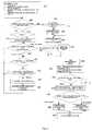
- FIGS. 1A through 1Gshows an application of the preferred embodiment of the present invention for a first initial condition of a stepper motor
- FIG. 2is a flow chart illustrating a preferred program flow of the present invention
- FIGS. 3A through 3Gshows an application of the preferred embodiment of the present invention for a second initial condition of a stepper motor
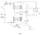
- FIG. 4is a block diagram of a preferred embodiment of the apparatus in accordance with the present invention.
- the present inventionis directed to a method and apparatus for reducing or eliminating turn on mechanical transients in a stepper motor resulting from an initial misalignment of an actual rotor position and a commanded rotor position which is based on phase currents of the motor.
- the present inventionavoids problems with the prior art by gradually increasing phase currents while sensing both rotor motion and the direction of rotor motion and using the information to “zero in” on the closest detent that matches a commanded rotor position based on electrical angle of the phase currents.
- the inventionpreferably comprises a shaft encoder mounted to a stepper motor shaft to sense the amount and direction of motor rotor motion as phase currents are increased. Having sensed motion, the currents are modified to change the direction of a magnetic field vector generated by the phase currents to find a magnetic field vector angle and rotor position that are consistent. When the actual rotor position is consistent with the position commanded by the phase currents, the phase currents are increased to their normal run values and an application program takes control using the found phase currents and rotor position as the application's initial state.
- an apparatus for reducing undesired motions during initialization of a stepper motor having a rotor and windingscomprises a rotary encoder for sensing direction of rotor rotation; a microcontroller responsive to signals from the rotary encoder for generating bidirectional motor control waveforms having variable digital amplitude values; at least one motor driver for receiving the motor control waveforms and translating the waveforms to drive the motor windings; and wherein the translated waveforms urge the rotor in a first direction and then a second direction to locate a desired rotor position.
- the motor driverapplies currents to the windings to form a magnetic field vector in a direction; the motor driver changes at least one motor phase current to rotate the magnetic field vector in a direction opposite to the direction of a first sensed rotor rotation by a first electrical angle and changes at least one motor phase current to rotate the magnetic field vector to a next position in a direction opposite to a second sensed rotor rotation by a second electrical angle; whereby the rotor is aligned with the magnetic field vector in its next position.
- the first mentioned sensed direction of rotor rotationis in a clockwise direction and the first mentioned rotation of the magnetic field vector is in the counterclockwise direction.
- the second mentioned sensed direction of rotor rotationis in a counterclockwise direction and the second mentioned rotation of the magnetic field vector is in the clockwise direction.
- the first mentioned sensed direction of rotor rotationis in a counterclockwise direction and the first mentioned rotation of the magnetic field vector is in the clockwise direction.
- the second mentioned sensed direction of rotor rotationis in a counterclockwise direction and the second mentioned rotation of the magnetic field vector is in the clockwise direction.
- the microcontroller and the at least one motor driverare combined in a single stepper motor controller.
- translating the waveformsmay include converting digital amplitude values into analog amplitude values.
- a method for reducing undesired motions during initialization of a stepper motor having a rotary encoder coupled thereto, said stepper motor having a rotor and phase windings under control of a microcontrolleris provided and preferably comprises the steps of applying currents to the phase windings to form a magnetic field vector in a direction; sensing a direction of rotor rotation; changing at least one motor phase current to rotate the magnetic field vector in a direction opposite to the direction of first sensed rotor rotation by a first electrical angle; sensing a direction of rotor rotation; changing at least one motor phase current to rotate the magnetic field vector to a next position in a direction opposite to the second sensed rotor rotation by a second electrical angle; and ending initialization, whereby the rotor is aligned with the magnetic field vector in its next position.
- the first electrical angleis at least essentially 90 degrees and the second electrical angle is at least essentially 45 degrees.
- the first mentioned sensed direction of rotor rotationis in a clockwise direction and the first mentioned rotation of the magnetic field vector is in the counterclockwise direction and the second mentioned sensed direction of rotor rotation is in a counterclockwise direction and the second mentioned rotation of the magnetic field vector is in the clockwise direction.
- the first mentioned sensed direction of rotor rotationis in a counterclockwise direction and the first mentioned rotation of the magnetic field vector is in the clockwise direction and the second mentioned sensed direction of rotor rotation is in a counterclockwise direction and the second mentioned rotation of the magnetic field vector is in the clockwise direction.
- the method for reducing undesired motions during initialization of a stepper motor having a rotary encoder coupled theretocomprises applying currents to the phase windings to form a magnetic field vector in a direction and causing the rotor to rotate in one of a clockwise or counterclockwise direction; changing at least one motor phase current to rotate the magnetic field vector in a direction opposite to the direction of rotor rotation by a first electrical angle and causing the rotor to either (i) rotate in an opposite direction from the first mentioned rotated direction or (ii) continue to rotate in the first mentioned rotated direction; changing at least one motor phase current to rotate the magnetic field vector to a next position in a direction opposite to direction of rotor rotation by a second electrical angle; and ending initialization, whereby the rotor is urged to an initialized position such that it is aligned with the next position of the magnetic field vector.
- FIGS. 1 a though 1 gA best method for carrying out the invention is described with the aid of simplified motor model 100 shown in FIGS. 1 a though 1 g and the flow chart of FIG. 2 .
- FIGS. 3 a through 3 gare used to show a different initial state than shown in FIGS. 1 a though 1 g .
- Motor 100is a 4 pole permanent magnet stepper motor.
- Motor 100includes poles 101 - 104 and permanent magnet rotor 105 having a north and south pole as indicated. Power has not been applied to any portion of the motor 100 in FIG. 1 a.
- the flow chart of FIG. 2starts at block 202 where, among other actions, the phase currents are initialized at 0.4% of rated run current and applied so that the poles have the polarities shown in FIG. 1 b and yield a net magnetic field in the direction shown by vector 110 .
- the embedded software in microcontroller 405sequentially performs the tasks described in blocks 205 , 210 , 215 , 220 , 235 and 240 then back to block 205 of the flow chart in FIG. 2 .
- the initial program processes in the flow chart of FIG. 2is dependent upon whether the process has timed out or motion is detected due to phase currents having increased to a level to cause motion of rotor 110 (shown by arrow 120 ) due to the net urging magnetic field at line 110 of FIGS. 1 b and 1 c.
- phase currentsare increased at about 0.4% per pass through block 215 through block 240 at a rate of approximately 0.8% to 2% per ms.
- trial parameteris equal to 1 so that, as described in block 270 , the next pass through blocks 205 , 210 , 215 , 220 , 235 and 240 will be with magnetic field vector 110 offset from its initial value (as indicated by vector 110 in FIG. 1 b ) by 1 step or 90 degrees.
- the trial parameteris 2 then the next field angle change is set to 1 ⁇ 2 step or 45 degrees.
- the offset directionis established based on the direction of rotor 105 rotation as determined at block 276 . It has been discovered that it is advantageous to include blocks 272 and 274 in the subroutine starting at block 268 to accommodate delays due to coil time constants and effects due to the inertia of rotor 105 respectively.
- magnetic field vector 110causes rotation of rotor 110 to start rotating in the clockwise direction shown by arrow 120 .
- magnetic field vector 110is moved 90 degrees counterclockwise and is at the position shown in FIGS. 1 d and 1 e.
- the magnetic vector 110again points in the direction shown in FIG. 3 a .
- vector 110urges rotor 105 to start rotation in a counterclockwise direction with the resulting motion is sensed by rotary encoder 430 of FIG. 4 . Since rotor 105 movement in FIG. 3 c is counterclockwise, the magnetic field indicated by vector 110 is therefore moved clockwise by 1 full step or 90 degrees as shown in FIGS. 3 d and 3 e and trial is increased by 1 to 2.
- block 210causes phase currents to hold at their value from trial 1 while rotor 105 continues to rotate in a counterclockwise direction trying to align with vector 110 in FIG. 3( e ).
- Block 240then senses that rotor 105 is still moving so that processing continues in the subroutine starting at block 268 where vector 110 is advanced clockwise by 1 ⁇ 2 step or 45 degrees into position shown in FIG. 3 f . With vector 110 in the position shown in FIG. 3 f rotor 105 is urged in a clockwise direction coming into a position that is consistent with vector 110 .
- microcontroller 405receives step and direction commands from an over-all application while drivers 410 and 415 may receive a brake command from the application program.
- Microcontroller 405is preferably a Microchip 16F685 and contains all code necessary to interface with the application program and to implement the flow chart of FIG. 2 .
- Drivers 410 and 415are preferably LMD 18245T and translate the desired coil currents from their digital format at the output of microcontroller 405 to analog values required by the phase windings of motor 405 .
- motion controlis configured for 16 level microstepping using M1-M4 inputs of each of drivers 410 and 415 .
- DAC 420advantageously provides the additional resolution needed to achieve the preferred current increments of 0.4% of running current.
- DAC 420is activated during the initialization stage of block 202 and deactivated (no pre-scaling) after program flow passes through block 265 and control passes to the application program that directs microcontroller 405 and hence stepper motor 425 .
- a System Semiconductor Motion Controller M3001is used to integrate the functionality of microcontroller 405 , DAC 420 and drivers 410 and 415 while providing addition control flexibility.
- motor 100is described and or diagrammatically shown as a 2 phase motor, 4 pole permanent magnet stepper motor, the motor may also be a multiple phase reluctance type motor with multiple poles or a hybrid type motor combining the features of a reluctance motor and permanent magnet motor combining the features of both types.
- motor 100is described and or diagrammatically shown as a 2 phase motor, 4 pole permanent magnet stepper motor, the motor may also be a multiple phase reluctance type motor with multiple poles or a hybrid type motor combining the features of a reluctance motor and permanent magnet motor combining the features of both types.
- the distribution of components as set forth aboveis exemplary and should not be considered limiting.
Landscapes
- Engineering & Computer Science (AREA)
- Power Engineering (AREA)
- Control Of Stepping Motors (AREA)
Abstract
Description
Claims (17)
Priority Applications (2)
| Application Number | Priority Date | Filing Date | Title |
|---|---|---|---|
| US12/240,224US8344681B2 (en) | 2008-09-29 | 2008-09-29 | Apparatus and method for minimizing undesirable stepper motor rotor motions |
| PCT/US2009/052206WO2010036450A1 (en) | 2008-09-29 | 2009-07-30 | Apparatus and method for minimizing undesirable stepper motor rotor motions |
Applications Claiming Priority (1)
| Application Number | Priority Date | Filing Date | Title |
|---|---|---|---|
| US12/240,224US8344681B2 (en) | 2008-09-29 | 2008-09-29 | Apparatus and method for minimizing undesirable stepper motor rotor motions |
Publications (2)
| Publication Number | Publication Date |
|---|---|
| US20100079102A1 US20100079102A1 (en) | 2010-04-01 |
| US8344681B2true US8344681B2 (en) | 2013-01-01 |
Family
ID=42056700
Family Applications (1)
| Application Number | Title | Priority Date | Filing Date |
|---|---|---|---|
| US12/240,224Expired - Fee RelatedUS8344681B2 (en) | 2008-09-29 | 2008-09-29 | Apparatus and method for minimizing undesirable stepper motor rotor motions |
Country Status (2)
| Country | Link |
|---|---|
| US (1) | US8344681B2 (en) |
| WO (1) | WO2010036450A1 (en) |
Families Citing this family (5)
| Publication number | Priority date | Publication date | Assignee | Title |
|---|---|---|---|---|
| EP2672834B2 (en) | 2011-02-10 | 2022-11-09 | Cargill Inc. | Process for the production of a refined oil |
| US20150216495A1 (en)* | 2014-02-05 | 2015-08-06 | Gabriel Gonzalez | Robotically assisted self-aligning portable x-ray machine |
| WO2018137179A1 (en) | 2017-01-25 | 2018-08-02 | Microsoft Technology Licensing, Llc. | Stepper motor for use in rotary control assembly of input device |
| WO2020125957A1 (en)* | 2018-12-18 | 2020-06-25 | Robert Bosch Gmbh | Brushless electrical machine |
| CN114764259A (en)* | 2021-01-11 | 2022-07-19 | 台达电子企业管理(上海)有限公司 | Current control device and power conversion system using the same |
Citations (18)
| Publication number | Priority date | Publication date | Assignee | Title |
|---|---|---|---|---|
| US3586953A (en) | 1967-09-22 | 1971-06-22 | Fairchild Camera Instr Co | Stepper motor control system |
| US4074179A (en)* | 1975-06-16 | 1978-02-14 | Warner Electric Brake & Clutch Company | Position detection methods and apparatus for stepping motors |
| US4851755A (en) | 1988-03-01 | 1989-07-25 | Ampex Corporation | Low power stepper motor drive system and method |
| US5189355A (en) | 1992-04-10 | 1993-02-23 | Ampex Corporation | Interactive rotary controller system with tactile feedback |
| US5929589A (en)* | 1996-11-11 | 1999-07-27 | Minebea Co., Ltd. | Stepping motor drive and a method of driving same |
| US5990651A (en)* | 1997-07-28 | 1999-11-23 | Nec Corporation | Stepping motor drive apparatus and stepping motor |
| US6013999A (en)* | 1998-09-21 | 2000-01-11 | The United States Of America As Represented By The Administrator Of The National Aeronautics And Space Administration | Stepper motor control that adjusts to motor loading |
| US6271641B1 (en)* | 1999-03-29 | 2001-08-07 | Matsushita Electric Industrial Co., Ltd. | Step motor driving device |
| US20020185926A1 (en)* | 2001-05-01 | 2002-12-12 | King Kenyon M. | Systems and methods of electric motor control |
| US20030155883A1 (en)* | 2002-02-19 | 2003-08-21 | Dresser, Inc. | Stall detection in stepper motors |
| US6850026B2 (en)* | 2002-03-15 | 2005-02-01 | Japan Servo Co., Ltd. | Stepping motor driver |
| US6853162B2 (en)* | 2002-12-05 | 2005-02-08 | Visteon Global Technologies, Inc. | Re-zeroing of a stepper motor without noise or movement |
| US7026773B2 (en) | 2003-03-14 | 2006-04-11 | Petersen Technology Corporation | Multiphase motors with single point sensing based commutation |
| US7129670B2 (en) | 2003-06-06 | 2006-10-31 | Yazaki Corporation | Drive device for stepper motor and indicating apparatus using the same |
| US7439701B2 (en)* | 2006-06-26 | 2008-10-21 | Yazaki Corporation | Method and device for detecting initial excitation phase of stepping motor |
| US7495409B2 (en)* | 2006-10-30 | 2009-02-24 | David Coutu | Method and apparatus for eliminating stall and cogging in multi-phase stepping motors |
| US20100289444A1 (en)* | 2009-05-13 | 2010-11-18 | Sanyo Electric Co., Ltd. | Driver circuit |
| US20110169442A1 (en)* | 2010-01-13 | 2011-07-14 | Canon Kabushiki Kaisha | Drive apparatus for stepping motor |
- 2008
- 2008-09-29USUS12/240,224patent/US8344681B2/ennot_activeExpired - Fee Related
- 2009
- 2009-07-30WOPCT/US2009/052206patent/WO2010036450A1/enactiveApplication Filing
Patent Citations (20)
| Publication number | Priority date | Publication date | Assignee | Title |
|---|---|---|---|---|
| US3586953A (en) | 1967-09-22 | 1971-06-22 | Fairchild Camera Instr Co | Stepper motor control system |
| US4074179A (en)* | 1975-06-16 | 1978-02-14 | Warner Electric Brake & Clutch Company | Position detection methods and apparatus for stepping motors |
| US4851755A (en) | 1988-03-01 | 1989-07-25 | Ampex Corporation | Low power stepper motor drive system and method |
| US5189355A (en) | 1992-04-10 | 1993-02-23 | Ampex Corporation | Interactive rotary controller system with tactile feedback |
| US5929589A (en)* | 1996-11-11 | 1999-07-27 | Minebea Co., Ltd. | Stepping motor drive and a method of driving same |
| US5990651A (en)* | 1997-07-28 | 1999-11-23 | Nec Corporation | Stepping motor drive apparatus and stepping motor |
| US6013999A (en)* | 1998-09-21 | 2000-01-11 | The United States Of America As Represented By The Administrator Of The National Aeronautics And Space Administration | Stepper motor control that adjusts to motor loading |
| US6271641B1 (en)* | 1999-03-29 | 2001-08-07 | Matsushita Electric Industrial Co., Ltd. | Step motor driving device |
| US20020185926A1 (en)* | 2001-05-01 | 2002-12-12 | King Kenyon M. | Systems and methods of electric motor control |
| US6586898B2 (en)* | 2001-05-01 | 2003-07-01 | Magnon Engineering, Inc. | Systems and methods of electric motor control |
| US20030155883A1 (en)* | 2002-02-19 | 2003-08-21 | Dresser, Inc. | Stall detection in stepper motors |
| US6667595B2 (en)* | 2002-02-19 | 2003-12-23 | Dresser, Inc. | Stall detection in stepper motors |
| US6850026B2 (en)* | 2002-03-15 | 2005-02-01 | Japan Servo Co., Ltd. | Stepping motor driver |
| US6853162B2 (en)* | 2002-12-05 | 2005-02-08 | Visteon Global Technologies, Inc. | Re-zeroing of a stepper motor without noise or movement |
| US7026773B2 (en) | 2003-03-14 | 2006-04-11 | Petersen Technology Corporation | Multiphase motors with single point sensing based commutation |
| US7129670B2 (en) | 2003-06-06 | 2006-10-31 | Yazaki Corporation | Drive device for stepper motor and indicating apparatus using the same |
| US7439701B2 (en)* | 2006-06-26 | 2008-10-21 | Yazaki Corporation | Method and device for detecting initial excitation phase of stepping motor |
| US7495409B2 (en)* | 2006-10-30 | 2009-02-24 | David Coutu | Method and apparatus for eliminating stall and cogging in multi-phase stepping motors |
| US20100289444A1 (en)* | 2009-05-13 | 2010-11-18 | Sanyo Electric Co., Ltd. | Driver circuit |
| US20110169442A1 (en)* | 2010-01-13 | 2011-07-14 | Canon Kabushiki Kaisha | Drive apparatus for stepping motor |
Also Published As
| Publication number | Publication date |
|---|---|
| US20100079102A1 (en) | 2010-04-01 |
| WO2010036450A1 (en) | 2010-04-01 |
Similar Documents
| Publication | Publication Date | Title |
|---|---|---|
| US8344681B2 (en) | Apparatus and method for minimizing undesirable stepper motor rotor motions | |
| EP3568909B1 (en) | Force feel using a brushless dc motor | |
| US6400109B1 (en) | Electronic commutated motor with commutation signal | |
| US5350984A (en) | Method and apparatus for starting a brushless DC motor | |
| JP3385617B2 (en) | Starting method of permanent magnet type synchronous motor with rotation position detector and motor control device | |
| JP4959460B2 (en) | Motor starting device and motor starting method | |
| US20030080729A1 (en) | System and method for enabling a high torque/high speed brushless DC motor | |
| US20020021098A1 (en) | Device and method for starting a brushless motor | |
| US9590541B2 (en) | Method and apparatus for control of electrical machines | |
| US6803739B2 (en) | Method and apparatus for controlling synchronous motor | |
| US9871485B2 (en) | Stepper motor driver circuit | |
| US8373369B2 (en) | Method and amplifier for operating a synchronous motor | |
| CN105322848A (en) | Starting method and system for permanent magnet synchronous motor | |
| JP6619382B2 (en) | Motor drive control device and control method of motor drive control device | |
| JP2000209888A (en) | Control device for brushless motor | |
| JP7271318B2 (en) | MOTOR CONTROL DEVICE, MOTOR CONTROL METHOD, AND OPTICAL DEVICE | |
| US20220173675A1 (en) | Method for the vibration-reduced operation of a bldc motor | |
| JP4416541B2 (en) | Stepping motor control method | |
| EP3832879A1 (en) | Control of a single coil bldc motor | |
| JP2002112577A (en) | Drive and driving method for brushless dc motor | |
| JP2016220274A (en) | Stepping motor controller | |
| JP6387899B2 (en) | Stepping motor controller | |
| JP3244800B2 (en) | Starting the sensorless motor | |
| US20050140320A1 (en) | Drive control device for direct current motor | |
| CN119906303A (en) | A stepper motor control method, device and medium based on pre-tightening |
Legal Events
| Date | Code | Title | Description |
|---|---|---|---|
| AS | Assignment | Owner name:INTELLIGENT MOTION SYSTEMS, INC.,CONNECTICUT Free format text:ASSIGNMENT OF ASSIGNORS INTEREST;ASSIGNOR:SERVIDONE, FRANCESCO;REEL/FRAME:021695/0399 Effective date:20080926 Owner name:INTELLIGENT MOTION SYSTEMS, INC., CONNECTICUT Free format text:ASSIGNMENT OF ASSIGNORS INTEREST;ASSIGNOR:SERVIDONE, FRANCESCO;REEL/FRAME:021695/0399 Effective date:20080926 | |
| ZAAA | Notice of allowance and fees due | Free format text:ORIGINAL CODE: NOA | |
| ZAAB | Notice of allowance mailed | Free format text:ORIGINAL CODE: MN/=. | |
| STCF | Information on status: patent grant | Free format text:PATENTED CASE | |
| FPAY | Fee payment | Year of fee payment:4 | |
| MAFP | Maintenance fee payment | Free format text:PAYMENT OF MAINTENANCE FEE, 8TH YEAR, LARGE ENTITY (ORIGINAL EVENT CODE: M1552); ENTITY STATUS OF PATENT OWNER: LARGE ENTITY Year of fee payment:8 | |
| AS | Assignment | Owner name:SCHNEIDER ELECTRIC MOTION USA, INC., CONNECTICUT Free format text:CHANGE OF NAME;ASSIGNOR:INTELLIGENT MOTION SYSTEMS, INC.;REEL/FRAME:056679/0479 Effective date:20091204 | |
| AS | Assignment | Owner name:NOVANTA CORPORATION, MASSACHUSETTS Free format text:ASSIGNMENT OF ASSIGNORS INTEREST;ASSIGNOR:NOVANTA MOTION USA INC.;REEL/FRAME:057614/0189 Effective date:20210921 Owner name:NOVANTA MOTION USA INC., MASSACHUSETTS Free format text:CHANGE OF NAME;ASSIGNOR:SCHNEIDER ELECTRIC MOTION USA, INC.;REEL/FRAME:057619/0502 Effective date:20210901 | |
| FEPP | Fee payment procedure | Free format text:MAINTENANCE FEE REMINDER MAILED (ORIGINAL EVENT CODE: REM.); ENTITY STATUS OF PATENT OWNER: LARGE ENTITY | |
| LAPS | Lapse for failure to pay maintenance fees | Free format text:PATENT EXPIRED FOR FAILURE TO PAY MAINTENANCE FEES (ORIGINAL EVENT CODE: EXP.); ENTITY STATUS OF PATENT OWNER: LARGE ENTITY | |
| STCH | Information on status: patent discontinuation | Free format text:PATENT EXPIRED DUE TO NONPAYMENT OF MAINTENANCE FEES UNDER 37 CFR 1.362 | |
| FP | Lapsed due to failure to pay maintenance fee | Effective date:20250101 | |
| AS | Assignment | Owner name:BANK OF AMERICA, N.A., TEXAS Free format text:SECURITY INTEREST;ASSIGNORS:NOVANTA CORPORATION;ATI INDUSTRIAL AUTOMATION, INC.;NOVANTA TECHNOLOGIES UK LIMITED;AND OTHERS;REEL/FRAME:071650/0222 Effective date:20250627 |