US8343423B2 - Automatic analyzer - Google Patents
Automatic analyzerDownload PDFInfo
- Publication number
- US8343423B2 US8343423B2US12/336,968US33696808AUS8343423B2US 8343423 B2US8343423 B2US 8343423B2US 33696808 AUS33696808 AUS 33696808AUS 8343423 B2US8343423 B2US 8343423B2
- Authority
- US
- United States
- Prior art keywords
- sample
- diluted sample
- diluted
- analysis
- reagent
- Prior art date
- Legal status (The legal status is an assumption and is not a legal conclusion. Google has not performed a legal analysis and makes no representation as to the accuracy of the status listed.)
- Expired - Fee Related, expires
Links
Images


Classifications
- G—PHYSICS
- G01—MEASURING; TESTING
- G01N—INVESTIGATING OR ANALYSING MATERIALS BY DETERMINING THEIR CHEMICAL OR PHYSICAL PROPERTIES
- G01N35/00—Automatic analysis not limited to methods or materials provided for in any single one of groups G01N1/00 - G01N33/00; Handling materials therefor
- G01N35/00584—Control arrangements for automatic analysers
- G01N35/00594—Quality control, including calibration or testing of components of the analyser
- G01N35/00613—Quality control
- G01N35/00663—Quality control of consumables
- G—PHYSICS
- G01—MEASURING; TESTING
- G01N—INVESTIGATING OR ANALYSING MATERIALS BY DETERMINING THEIR CHEMICAL OR PHYSICAL PROPERTIES
- G01N35/00—Automatic analysis not limited to methods or materials provided for in any single one of groups G01N1/00 - G01N33/00; Handling materials therefor
- G01N35/00584—Control arrangements for automatic analysers
- G01N35/00722—Communications; Identification
- G01N2035/00891—Displaying information to the operator
- G01N2035/0091—GUI [graphical user interfaces]
- G—PHYSICS
- G01—MEASURING; TESTING
- G01N—INVESTIGATING OR ANALYSING MATERIALS BY DETERMINING THEIR CHEMICAL OR PHYSICAL PROPERTIES
- G01N35/00—Automatic analysis not limited to methods or materials provided for in any single one of groups G01N1/00 - G01N33/00; Handling materials therefor
- G01N35/10—Devices for transferring samples or any liquids to, in, or from, the analysis apparatus, e.g. suction devices, injection devices
- G01N2035/1027—General features of the devices
- G01N2035/1032—Dilution or aliquotting
- G—PHYSICS
- G01—MEASURING; TESTING
- G01N—INVESTIGATING OR ANALYSING MATERIALS BY DETERMINING THEIR CHEMICAL OR PHYSICAL PROPERTIES
- G01N35/00—Automatic analysis not limited to methods or materials provided for in any single one of groups G01N1/00 - G01N33/00; Handling materials therefor
- G01N35/00584—Control arrangements for automatic analysers
Definitions
- the present inventionrelates to automatic analyzers for performing qualitative/quantitative analysis of samples such as blood and urine.
- the inventionmore particularly relates to an automatic analyzer including: a parent sample vessel holding unit for holding a parent sample; a diluted sample vessel holding unit in which a diluted sample vessel is placed, the diluted sample vessel holding a diluted sample made by diluting, with a diluent, a sample pipetted from the parent sample; and a reaction vessel in which the analysis, inspection, and measurement of the diluted sample are performed.
- a plurality of measurement items of the analysis and inspectionare requested for one patient sample.
- all requested measurement itemsmay not be completely measured because the fluid volume is small.
- JP-A-8-194004discloses an automatic analyzer that uses a method in which a parent sample is diluted with diluent to ensure the fluid volume required for measurement items.
- the above-described automatic analyzerstores, in a diluted sample vessel, a diluted sample remains after analysis and inspection to thereby meet a request for reinspection.
- the diluted samplemay dry and adhere to a diluted sample vessel, which leads to difficulty in washing and deterioration of the diluted sample itself. Consequently the diluted sample will become unsuitable for the qualitative/quantitative analysis and inspection.
- An object of the present inventionis to provide an automatic analyzer that creates few, if any, inconveniences including a case where a diluted sample becomes unsuitable for the qualitative/quantitative analysis and inspection because of the adhesion of the diluted sample due to drying, and because of the deterioration of the diluted sample.
- another object of the present inventionis to provide an automatic analyzer that is capable of checking, before measurement for the analysis and inspection is executed, whether or not all requested measurement items for the analysis and inspection can be completely measured, and that is capable of checking, before measurement for the analysis and inspection is executed, the time it takes before measurement of all samples is completed.
- an automatic analyzerfor performing the analysis and inspection of various kinds of samples including a parent sample, a diluted sample, and a combination sample in which the diluted sample and the parent sample are used in combination, said automatic analyzer comprising:
- a parent sample vessel holding unitin which a parent sample vessel containing a parent sample is placed
- a diluted sample vessel holding unitin which a diluted sample vessel containing a diluted sample made by diluting the parent sample is placed;
- said automatic analyzerhas a function of discarding, from the diluted sample vessel, the remaining diluted sample that remains after pipetting in the analysis and inspection, and holding the remaining diluted sample in the diluted sample vessel.
- an automatic analyzerfor performing the analysis and inspection of various kinds of samples including a parent sample, a diluted sample, and a combination sample in which the diluted sample and the parent sample are used in combination, said automatic analyzer comprising:
- a parent sample vessel holding unitin which a parent sample vessel containing a parent sample is placed
- a diluted sample vessel holding unitin which a diluted sample vessel containing a diluted sample made by diluting the parent sample is placed,
- said automatic analyzerhaving a function of, before the analysis and inspection, knowing how many times and how much the analysis and inspection can be executed on the basis of the amount of the diluted sample that has been diluted.
- the automatic analyzerfurther includes a display unit for displaying, on a screen, various kinds of information about the analysis and inspection.
- a display unitfor displaying, on a screen, various kinds of information about the analysis and inspection.
- the estimated length of time it takes to complete the analysis and inspection of the whole requested diluted sampleis displayed on the display unit.
- the automatic analyzerhas a function of discarding, from the diluted sample vessel, the remaining diluted sample that remains after pipetting in analysis and inspection, and holding the remaining diluted sample in the diluted sample vessel.
- the automatic analyzertherefore, can meet a request for remeasurement using the remaining diluted sample. If the elapsed time during which a diluted sample is held becomes too long, the diluted sample is discarded. This makes it possible to make full use of the diluted sample, and to prevent a failure of measurement for the reanalysis and reinspection from occurring which would result from the adhesion of a diluted sample to the diluted sample vessel due to drying and the deterioration of the diluted sample.
- the automatic analyzeris capable of, before the analysis and inspection, knowing how many times and how much the analysis and inspection can be performed on the basis of the amount of the diluted sample that has been diluted, and is capable of displaying, on the display unit, the estimated length of time it takes to complete the analysis and inspection of the whole requested diluted sample.
- FIG. 1is a diagram illustrating an item selection screen used to request measurement items that are displayed on a display unit included in an operation unit of an automatic analyzer according to an embodiment of the present invention
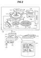
- FIG. 2is a diagram schematically illustrating the overall configuration of an automatic analyzer based on principles according to the embodiment of the present invention
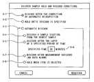
- FIG. 3is a diagram illustrating a diluted sample hold and discard conditions setting screen according to the embodiment of the present invention.
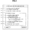
- FIG. 4is a diagram illustrating a pre-analysis check screen used to check before measurement whether or not each diluted sample can be measured according to the embodiment of the present invention.
- FIG. 5is a diagram illustrating an analysis start screen used to start measurement of samples such as a diluted sample according to the embodiment of the present invention.
- a parent sampleis diluted with diluent to increase the amount of sample so that many analysis and inspection items for the reanalysis, reinspection, and remeasurement can be handled (hereinafter the analysis and inspection are also merely called “measurement”).
- the diluted sampleis held over a period of time during which the diluted sample can be used for the analysis and inspection; and if the elapsed time during which the diluted sample is held becomes too long, the diluted sample is discarded.
- a display unitis used to display: an item selection screen used to request measurement of each measurement item; an analysis start screen used to start the measurement; and a pre-analysis check screen used to make a check before the measurement.
- an item selection screenused to request measurement of each measurement item
- an analysis start screenused to start the measurement
- a pre-analysis check screenused to make a check before the measurement.
- FIG. 2is a diagram schematically illustrating the overall configuration of an automatic analyzer based on principles of the invention.
- reference numeral 2 - 1denotes an operation unit.
- the operation unit 2 - 1is a computer equipped with peripheral devices.
- the peripheral devicesare a keyboard 2 - 2 for inputting data; a mouse 2 - 3 ; a display unit for displaying data 2 - 4 ; a printer 2 - 5 for printing data; an interface 2 - 6 through which a connection to an analyzing unit is made; and a storage device 2 - 7 for storing hold and discard conditions of a diluted sample and a state of the diluted sample.
- Reference numeral 2 - 8denotes an analyzing unit.
- the analyzing unit 2 - 8is connected to the operation unit 2 - 1 through the interface 2 - 6 .
- the analyzing unit 2 - 8includes a reaction disk 2 - 9 .
- a plurality of reaction vessels 2 - 10are disposed along the concentric circumference of the reaction disk 2 - 9 .
- Reference numeral 2 - 11denotes a reagent disk.
- a plurality of reagent bottles 2 - 12 containing various kinds of reagentsare disposed along the concentric circumference of the reagent disk 2 - 11 .
- Around the reaction disk 2 - 9are disposed a pipetting probe 2 - 13 for pipetting a diluted sample into the reaction disk 2 - 9 ; a mixer 2 - 14 ; a cleaning device 2 - 15 ; a light source 2 - 16 ; and a multiwavelength photometer 2 - 17 .
- a reagent pipetting probe 2 - 18is disposed between the reaction disk 2 - 9 and the reagent disk 2 - 11 .
- a diluted sample disk 2 - 19is disposed at a position adjacent to the reagent disk 2 - 11 in such a manner that the diluted sample disk 2 - 19 is associated with the circumference of the rotating diluted sample pipetting probe 2 - 13 .
- a plurality of diluted sample vessels 2 - 20are located on the diluted sample disk 2 - 19 .
- the reagent disk 2 - 11has the plurality of reagent bottles 2 - 12 thereon, each of which contains a reagent used to dilute a sample and/or a reagent used to analyze and inspect a sample.
- a rack transfer belt 2 - 24is extended at a position adjacent to the diluted sample disk 2 - 19 .
- a rack 2 - 22moves along the rack transfer belt 2 - 24 .
- a plurality of parent sample vessels 2 - 23 each containing a parent sampleare placed in the rack 2 - 22 .
- a parent sample pipetting probe 2 - 21is disposed between the diluted sample disk 2 - 19 and the rack transfer belt 2 - 24 .
- the operation of the above-described mechanismis totally controlled by the computer 2 - 26 through the interface 2 - 25 .
- An operatoruses the display unit 2 - 4 and the keyboard 2 - 2 (or the mouse 2 - 3 ) that are included in the operation unit 2 - 1 to give the analyzer a measurement instruction including requested measurement items.
- the measurement instructionis transmitted to the analyzing unit 2 - 8 through the interface 2 - 6 .
- the analyzing unit 2 - 8makes measurements in the following manner.
- the parent sample pipetting probe 2 - 21pipettes, into the diluted sample vessel 2 - 20 , the specified amount of parent sample contained in the parent sample vessel 2 - 23 .
- the rack transfer belt 2 - 24moves the rack 2 - 22 such that the next parent sample vessel 2 - 23 comes to a position immediately below the parent sample pipetting probe 2 - 21 .
- the rack 2 - 22is carried out by the rack transfer belt 2 - 24 .
- a diluent for diluting a sample contained in the diluted sample vessel 2 - 20is pipetted. More specifically, the reagent pipetting probe 2 - 18 sucks the diluent contained in the reagent bottle 2 - 12 , and then puts the sucked diluent into the diluted sample vessel 2 - 20 , whereby the sample is diluted.
- the diluted sample pipetting probe 2 - 13pipettes the specified amount of diluted sample contained in the diluted sample vessel 2 - 20 into each reaction vessel 2 - 10 such that the required number of items is satisfied.
- the diluted sample disk 2 - 19is rotated such that the next diluted sample vessel 2 - 20 comes at a position immediately below the diluted sample pipetting probe 2 - 13 .
- the rotational operation of the reaction disk 2 - 9causes the reaction vessel 2 - 10 , into which a diluted sample has been pipetted, to rotationally move on the reaction disk 2 - 9 .
- the reagent pipetting probe 2 - 18pipets a reagent contained in the reagent bottle 2 - 12 into the reaction vessel 2 - 10 containing the sample; the mixer 2 - 14 stirs the reaction solution; and the multiwavelength photometer 2 - 17 measures the absorbance by use of the light source 2 - 16 .
- the cleaning device 2 - 15cleans the reaction vessel 2 - 10 whose measurements have been completed.
- the absorbance signal representing the measured absorbanceis inputted into the computer 2 - 26 through an A/D converter 2 - 27 and the interface 2 - 25 . From this absorbance signal, on the basis of an analysis method that is set beforehand for each measurement item, calibration curve data is calculated for a standard solution sample from concentration data that is set, whereas concentration data is calculated for a patient sample and a control sample from the calibration curve data obtained by the measurements of the standard solution sample.
- the display unit 2 - 4 and the keyboard 2 - 2are used to execute the following processing: manually remeasuring measured samples; setting diluted sample hold and discard conditions; viewing unmeasurable measurement items; and viewing the length of time it takes until measurement of the whole requested diluted sample is completed.
- FIG. 1is a diagram illustrating an item selection screen used to issue a request for measurement items.
- samples to be measuredare selected.
- an automatic selection radio button 1 - 2a diluted sample is preferentially measured, and if the amount of a diluted sample is short, a parent sample thereof is used for measurement.
- a manual selection radio button 1 - 3three kinds of settings are available.
- the first one of the settingsis associated with a case where a parent sample check box 1 - 4 is selected. In this case, only a parent sample is used for measurement.
- This settingis used for first measurement, or when the parent sample residual is stored, it is used as remeasurement for measurement items for which measurements will be too low in sensitivity to make a precise measurement if a diluted sample is used for measurement.
- the second one of the settingsis associated with a case where a diluted sample check box 1 - 5 is selected.
- a diluted sampleis used for measurement.
- the diluted sample check box 1 - 5can be selected only when a diluted sample is prepared and diluted sample discard conditions are not satisfied.
- the diluted sample check box 1 - 5is used for measurement of an additional measurement item, and for remeasurement of a measurement item for which no trouble is caused in measurement even if a diluted sample is used for measurement.
- the third one of the settingsis associated with a case where both the parent sample check box 1 - 4 and the diluted sample check box 1 - 5 are selected. In this case, both a parent sample and a diluted sample are used.
- the third settingis used for, for example, a case where the amount of a diluted sample is not sufficient although the second setting is satisfied.
- Pressing a diluted sample button 1 - 6displays a diluted sample hold and discard conditions setting screen shown in FIG. 3 .
- This buttonis used to perform three kinds of settings of diluted sample hold and discard conditions.
- the first one of the settings of diluted sample hold and discard conditionsis associated with a case where a radio button 3 - 1 is selected for discarding a diluted sample after the completion of automatic reinspection.
- a radio button 3 - 1is selected for discarding a diluted sample after the completion of automatic reinspection.
- a diluted sampleis discarded after first measurement is executed and automatic reinspection of the first measurement is completed. In this case, remeasurement of the diluted sample cannot be carried out.
- the second one of the settingsis associated with a case where a radio button 3 - 2 is selected for holding a diluted sample until its discard is specified. According to the second setting, a diluted sample is held until the diluted sample is discarded based on discard specification to be performed on a pre-analysis check screen (shown in FIG. 4 ). The second setting is used when an operator determines timing at which a diluted sample is to be discarded.
- the third one of the settingsis associated with a case where a radio button 3 - 3 is selected for automatically discarding a diluted sample.
- Several discard conditionscan be set in the third setting.
- a radio button 3 - 4is selected for discarding a sample starting from the oldest one
- a diluted sampleis automatically discarded starting from the oldest one such that a diluted sample vessel is empty and thereby trouble is not caused in measurement by the automatic analyzer.
- a radio button 3 - 5is selected for discarding a diluted sample after the lapse of a specified period of time, a diluted sample for which the specified time inputted into a specified time edit box 3 - 6 has elapsed is automatically discarded.
- diluted sample selection settingscan be made irrespective of before or after the operation of the automatic analyzer, diluted samples are adapted for various kinds of operation modes.
- FIG. 4is a diagram illustrating a pre-analysis check screen.
- An indication 4 - 1schematically shows a pipetted sample disk having concentric rings which hold diluted sample vessels
- an indication 4 - 2schematically shows a diluted sample vessel.
- the indications 4 - 2 expressing diluted sample vesselsare disposed on the pipetted sample disk 4 - 1 .
- the pre-analysis check screenif the amount of diluted sample, the amount of reagent to be used, the amount of diluent, or the amount of washing agent is insufficient, they are highlighted with color and patterns in accordance with the causes of insufficiency as shown in FIG. 4 .
- measurement item names for which measurement cannot be performedare listed based on the amount of diluted sample, the amount of reagent, the amount of diluent, the amount of washing agent, and a requested measurement item, which are known at present.
- combo boxesallow an operator to eliminate causes for which a sample cannot be subjected to measurement before the execution of the measurement, or to accept or reject each measurement item.
- the length of time it takes until measurement of all samples is completedis displayed by a measurement-completion time text 4 - 7 .
- the remaining amount and the elapsed time after pipettingare displayed by a pipetted sample list box 4 - 8 for a diluted sample for each diluted sample.
- the remaining amountis to be displayed, the insufficient remaining amount is highlighted with a different color 4 - 9 .
- the elapsed timeis to be displayed, the elapsed time which has passed the discard specification time is highlighted with a different color 4 - 9 .
- a diluted samplecan be discarded.
- FIG. 5is a diagram illustrating an analysis start screen.
- the analysis start screenis used to specify the start of measurement.
- a modecan be selected from among the following three modes.
- a first modeis associated with a case where a pipetting and measurement radio button 5 - 2 is selected.
- the first modeis a mode in which both pipetting from a parent sample and measurement are executed.
- the second modeis associated with a case where a pipetting-only radio button 5 - 3 is selected.
- the second modeis a mode in which only pipetting from a parent sample is executed.
- a start button 5 - 6When a start button 5 - 6 is selected to execute only pipetting of the diluted sample from the parent sample in the second mode, it becomes possible to make a check in the pre-analysis check screen shown in FIG. 4 even in first measurement. If a check box 5 - 4 for starting measurement upon pre-analysis check OK is selected, measurement can be automatically started when all measurement items are judged to be measured by the pre-analysis check.
- the third modeis associated with a case where a measurement-only radio button 5 - 5 is selected.
- the third modeis a mode in which only measurement is executed. The measurement may be executed after the check and adjustment performed on the pre-analysis check screen shown in FIG. 4 .
- the diluted sample vesselsare located in the diluted sample vessel holding unit.
- vessels included in a reaction disk or a reagent diskmay also be used for a diluted sample vessel.
- vesselsmay be circularly placed in two or three layers on a reaction disk with diluted sample vessels and reaction vessels placed in combination.
- the present inventioncan be used for a wide range of automatic analyzers, each of which is capable of handling a diluted sample, capable of measuring a plurality of items for a sample, and capable of holding a sample pipetted from a parent sample.
Landscapes
- Engineering & Computer Science (AREA)
- Quality & Reliability (AREA)
- Physics & Mathematics (AREA)
- Health & Medical Sciences (AREA)
- Life Sciences & Earth Sciences (AREA)
- Chemical & Material Sciences (AREA)
- Analytical Chemistry (AREA)
- Biochemistry (AREA)
- General Health & Medical Sciences (AREA)
- General Physics & Mathematics (AREA)
- Immunology (AREA)
- Pathology (AREA)
- Automatic Analysis And Handling Materials Therefor (AREA)
Abstract
Description
Claims (12)
Applications Claiming Priority (2)
| Application Number | Priority Date | Filing Date | Title |
|---|---|---|---|
| JP2008-046172 | 2008-02-27 | ||
| JP2008046172AJP4659054B2 (en) | 2008-02-27 | 2008-02-27 | Automatic analyzer |
Publications (2)
| Publication Number | Publication Date |
|---|---|
| US20090214385A1 US20090214385A1 (en) | 2009-08-27 |
| US8343423B2true US8343423B2 (en) | 2013-01-01 |
Family
ID=40792602
Family Applications (1)
| Application Number | Title | Priority Date | Filing Date |
|---|---|---|---|
| US12/336,968Expired - Fee RelatedUS8343423B2 (en) | 2008-02-27 | 2008-12-17 | Automatic analyzer |
Country Status (4)
| Country | Link |
|---|---|
| US (1) | US8343423B2 (en) |
| EP (1) | EP2096446B1 (en) |
| JP (1) | JP4659054B2 (en) |
| CN (1) | CN101520465B (en) |
Cited By (7)
| Publication number | Priority date | Publication date | Assignee | Title |
|---|---|---|---|---|
| US20120294763A1 (en)* | 2008-10-31 | 2012-11-22 | Sysmex Corporation | Specimen analyzing apparatus and specimen analyzing method |
| US9097689B2 (en) | 2010-06-30 | 2015-08-04 | Sysmex Corporation | Throughput information generating apparatus of sample analyzer, sample analyzer, throughput information generating method of sample analyzer, and computer program product |
| US9335338B2 (en) | 2013-03-15 | 2016-05-10 | Toshiba Medical Systems Corporation | Automated diagnostic analyzers having rear accessible track systems and related methods |
| US9400285B2 (en) | 2013-03-15 | 2016-07-26 | Abbot Laboratories | Automated diagnostic analyzers having vertically arranged carousels and related methods |
| US20180113142A1 (en)* | 2015-03-02 | 2018-04-26 | Hitachi High-Technologies Corporation | Automatic analyzer |
| US10001497B2 (en) | 2013-03-15 | 2018-06-19 | Abbott Laboratories | Diagnostic analyzers with pretreatment carousels and related methods |
| US20210241868A1 (en)* | 2018-08-09 | 2021-08-05 | Foss Analytical A/S | Analysis instrument |
Families Citing this family (24)
| Publication number | Priority date | Publication date | Assignee | Title |
|---|---|---|---|---|
| US9389238B2 (en)* | 2009-09-28 | 2016-07-12 | Hitachi High-Technologies Corporation | Automatic analyzing device, information display method thereof, and information display system |
| US8992866B2 (en) | 2009-11-24 | 2015-03-31 | Siemens Healthcare Diagnostics Inc. | Automated, refrigerated specimen inventory management system |
| JP5686710B2 (en)* | 2011-09-21 | 2015-03-18 | 株式会社日立ハイテクノロジーズ | Automatic analyzer |
| JP2013167561A (en)* | 2012-02-16 | 2013-08-29 | Hitachi High-Technologies Corp | Automatic analyzer |
| JP6072450B2 (en)* | 2012-07-12 | 2017-02-01 | 株式会社日立ハイテクノロジーズ | Automatic analyzer |
| JP6177532B2 (en)* | 2013-01-23 | 2017-08-09 | 株式会社日立ハイテクノロジーズ | Automatic analysis system and control method |
| JP5951545B2 (en)* | 2013-03-29 | 2016-07-13 | シスメックス株式会社 | Sample analyzer, sample analysis method, and computer program |
| JP6259663B2 (en)* | 2014-01-07 | 2018-01-10 | 株式会社日立ハイテクノロジーズ | Automatic analyzer |
| DE112015001298A5 (en)* | 2014-03-17 | 2016-12-15 | Schaeffler Technologies AG & Co. KG | Plate carrier and coupling device with such a plate carrier |
| JP6771903B2 (en)* | 2016-02-29 | 2020-10-21 | シスメックス株式会社 | Specimen pretreatment device, sample pretreatment cartridge and sample pretreatment method |
| CN109690322B (en)* | 2016-09-21 | 2023-02-24 | 株式会社日立高新技术 | Automatic analysis device |
| CN109690324B (en)* | 2016-09-21 | 2022-09-27 | 株式会社日立高新技术 | Automatic analysis device, remote maintenance system, and maintenance method |
| JP6742963B2 (en) | 2017-07-25 | 2020-08-19 | 株式会社日立ハイテク | Automatic analyzer and image processing method |
| CN110892270B (en) | 2017-07-25 | 2021-10-26 | 株式会社日立高新技术 | Automatic analyzer |
| CN109959549A (en)* | 2017-12-25 | 2019-07-02 | 深圳迈瑞生物医疗电子股份有限公司 | Sample detection method and sample analyzer |
| JP2019120572A (en)* | 2018-01-04 | 2019-07-22 | 日本電子株式会社 | Automatic analyzer and re-inspection instruction system |
| JP6843800B2 (en)* | 2018-06-19 | 2021-03-17 | 日本電子株式会社 | Automatic analyzer and automatic analysis method |
| CN112867925A (en)* | 2018-10-23 | 2021-05-28 | 积水医疗株式会社 | Automatic sampler, automatic analyzer, sampling method, and automatic inspection method |
| WO2020085271A1 (en)* | 2018-10-23 | 2020-04-30 | 積水メディカル株式会社 | Autosampler, automatic analysis device, sampling method, and automatic inspection method |
| JP6768118B1 (en)* | 2019-06-18 | 2020-10-14 | シスメックス株式会社 | Specimen measurement method and sample measurement device |
| CN112577952A (en)* | 2019-09-30 | 2021-03-30 | 深圳迈瑞生物医疗电子股份有限公司 | Sample analysis device and sample dilution test method |
| JP2022071447A (en)* | 2020-10-28 | 2022-05-16 | 日本電子株式会社 | Automatic analyzer and automatic analysis method |
| CN117980746A (en)* | 2021-09-28 | 2024-05-03 | 株式会社日立高新技术 | Automatic analysis device and method of using the same |
| JP2023056431A (en)* | 2021-10-07 | 2023-04-19 | キヤノンメディカルシステムズ株式会社 | Autoanalyzer |
Citations (10)
| Publication number | Priority date | Publication date | Assignee | Title |
|---|---|---|---|---|
| JPH03140844A (en) | 1989-10-26 | 1991-06-14 | Shimadzu Corp | Multi-item analysis method using micro samples |
| US5314825A (en) | 1992-07-16 | 1994-05-24 | Schiapparelli Biosystems, Inc. | Chemical analyzer |
| US5320966A (en)* | 1987-11-13 | 1994-06-14 | Hitachi, Ltd. | Method for analyzing samples and automatic processor therefor |
| JPH0798320A (en) | 1993-09-29 | 1995-04-11 | Shimadzu Corp | Biochemical automatic analyzer |
| US5434083A (en)* | 1989-07-17 | 1995-07-18 | Hitachi, Ltd. | Method and apparatus for automatically analyzing a plurality of test items |
| JPH08194004A (en) | 1995-01-19 | 1996-07-30 | Jeol Ltd | Biochemical automatic analyzer |
| JPH08278313A (en) | 1995-04-06 | 1996-10-22 | Toshiba Medical Eng Co Ltd | Automatic chemical analyzer |
| EP0825445A2 (en) | 1996-08-21 | 1998-02-25 | JEOL Ltd. | Automatic biochemical analyzer |
| US5741461A (en)* | 1995-05-19 | 1998-04-21 | Hitachi, Ltd. | Automatic analyzer having cuvette cleaning control device |
| JP2007198986A (en) | 2006-01-30 | 2007-08-09 | Shimadzu Corp | Data processor for automatic analysis |
Family Cites Families (4)
| Publication number | Priority date | Publication date | Assignee | Title |
|---|---|---|---|---|
| JP2950698B2 (en)* | 1993-01-11 | 1999-09-20 | 株式会社日立製作所 | Automatic analyzer with washing function |
| JP3156550B2 (en)* | 1995-07-11 | 2001-04-16 | 株式会社日立製作所 | Reagent management method and apparatus |
| JP3558898B2 (en)* | 1998-11-05 | 2004-08-25 | 株式会社日立製作所 | Automatic analyzer and automatic analysis method |
| JP2000321283A (en)* | 1999-05-13 | 2000-11-24 | Toshiba Corp | Automatic analyzer |
- 2008
- 2008-02-27JPJP2008046172Apatent/JP4659054B2/enactiveActive
- 2008-12-17USUS12/336,968patent/US8343423B2/ennot_activeExpired - Fee Related
- 2009
- 2009-01-15EPEP09150640.2Apatent/EP2096446B1/ennot_activeCeased
- 2009-02-19CNCN2009100075007Apatent/CN101520465B/enactiveActive
Patent Citations (12)
| Publication number | Priority date | Publication date | Assignee | Title |
|---|---|---|---|---|
| US5320966A (en)* | 1987-11-13 | 1994-06-14 | Hitachi, Ltd. | Method for analyzing samples and automatic processor therefor |
| US5434083A (en)* | 1989-07-17 | 1995-07-18 | Hitachi, Ltd. | Method and apparatus for automatically analyzing a plurality of test items |
| JPH03140844A (en) | 1989-10-26 | 1991-06-14 | Shimadzu Corp | Multi-item analysis method using micro samples |
| US5314825A (en) | 1992-07-16 | 1994-05-24 | Schiapparelli Biosystems, Inc. | Chemical analyzer |
| JPH0798320A (en) | 1993-09-29 | 1995-04-11 | Shimadzu Corp | Biochemical automatic analyzer |
| JPH08194004A (en) | 1995-01-19 | 1996-07-30 | Jeol Ltd | Biochemical automatic analyzer |
| US5876668A (en) | 1995-01-19 | 1999-03-02 | Joel Ltd. | Automatic biochemical analyzer |
| JPH08278313A (en) | 1995-04-06 | 1996-10-22 | Toshiba Medical Eng Co Ltd | Automatic chemical analyzer |
| US5741461A (en)* | 1995-05-19 | 1998-04-21 | Hitachi, Ltd. | Automatic analyzer having cuvette cleaning control device |
| EP0825445A2 (en) | 1996-08-21 | 1998-02-25 | JEOL Ltd. | Automatic biochemical analyzer |
| US6146592A (en)* | 1996-08-21 | 2000-11-14 | Jeol Ltd. | Automatic biochemical analyzer |
| JP2007198986A (en) | 2006-01-30 | 2007-08-09 | Shimadzu Corp | Data processor for automatic analysis |
Cited By (18)
| Publication number | Priority date | Publication date | Assignee | Title |
|---|---|---|---|---|
| US20120294763A1 (en)* | 2008-10-31 | 2012-11-22 | Sysmex Corporation | Specimen analyzing apparatus and specimen analyzing method |
| US9068956B2 (en)* | 2008-10-31 | 2015-06-30 | Sysmex Corporation | Specimen analyzing apparatus and specimen analyzing method |
| US9097689B2 (en) | 2010-06-30 | 2015-08-04 | Sysmex Corporation | Throughput information generating apparatus of sample analyzer, sample analyzer, throughput information generating method of sample analyzer, and computer program product |
| US10267818B2 (en) | 2013-03-15 | 2019-04-23 | Abbott Laboratories | Automated diagnostic analyzers having rear accessible track systems and related methods |
| US11435372B2 (en) | 2013-03-15 | 2022-09-06 | Abbott Laboratories | Diagnostic analyzers with pretreatment carousels and related methods |
| US12228583B2 (en) | 2013-03-15 | 2025-02-18 | Abbott Laboratories | Automated diagnostic analyzers having vertically arranged carousels and related methods |
| US10001497B2 (en) | 2013-03-15 | 2018-06-19 | Abbott Laboratories | Diagnostic analyzers with pretreatment carousels and related methods |
| US10197585B2 (en) | 2013-03-15 | 2019-02-05 | Abbott Laboratories | Automated diagnostic analyzers having vertically arranged carousels and related methods |
| US9335338B2 (en) | 2013-03-15 | 2016-05-10 | Toshiba Medical Systems Corporation | Automated diagnostic analyzers having rear accessible track systems and related methods |
| US10775398B2 (en) | 2013-03-15 | 2020-09-15 | Abbott Laboratories | Automated diagnostic analyzers having vertically arranged carousels and related methods |
| US12007403B2 (en) | 2013-03-15 | 2024-06-11 | Abbott Laboratories | Automated diagnostic analyzers having rear accessible track systems and related methods |
| US11536739B2 (en) | 2013-03-15 | 2022-12-27 | Abbott Laboratories | Automated diagnostic analyzers having vertically arranged carousels and related methods |
| US11125766B2 (en) | 2013-03-15 | 2021-09-21 | Abbott Laboratories | Automated diagnostic analyzers having rear accessible track systems and related methods |
| US9400285B2 (en) | 2013-03-15 | 2016-07-26 | Abbot Laboratories | Automated diagnostic analyzers having vertically arranged carousels and related methods |
| US10895579B2 (en)* | 2015-03-02 | 2021-01-19 | Hitachi High-Tech Corporation | Automatic analyzer |
| US20180113142A1 (en)* | 2015-03-02 | 2018-04-26 | Hitachi High-Technologies Corporation | Automatic analyzer |
| US20210241868A1 (en)* | 2018-08-09 | 2021-08-05 | Foss Analytical A/S | Analysis instrument |
| US11869636B2 (en)* | 2018-08-09 | 2024-01-09 | Foss Analytical A/S | Analysis instrument |
Also Published As
| Publication number | Publication date |
|---|---|
| EP2096446A2 (en) | 2009-09-02 |
| US20090214385A1 (en) | 2009-08-27 |
| EP2096446A3 (en) | 2011-02-23 |
| EP2096446B1 (en) | 2017-07-19 |
| CN101520465A (en) | 2009-09-02 |
| JP4659054B2 (en) | 2011-03-30 |
| JP2009204409A (en) | 2009-09-10 |
| CN101520465B (en) | 2013-07-10 |
Similar Documents
| Publication | Publication Date | Title |
|---|---|---|
| US8343423B2 (en) | Automatic analyzer | |
| US8329103B2 (en) | Sample analyzer and method for analyzing samples | |
| EP1873530B1 (en) | Sample analyzer | |
| JP3990944B2 (en) | Automatic analyzer | |
| US8535607B2 (en) | Sample analyzer | |
| JP5993865B2 (en) | Automatic analysis system | |
| US20080056944A1 (en) | Automated analyzer | |
| EP2878956B1 (en) | Automated analyzer | |
| JP2008058129A (en) | Automatic analyzer | |
| US11054433B2 (en) | Automated analyzer and control method for same | |
| WO2003107012A1 (en) | Automatic analysis device, measurement device, and measurement result management method | |
| CN106461691A (en) | Automatic analysis device | |
| JP5517160B2 (en) | Automatic analyzer | |
| JP5271929B2 (en) | Automatic analyzer | |
| JP2013068441A (en) | Automatic analyzer | |
| US11009519B2 (en) | Automated analyzer and image processing method | |
| JP5505983B2 (en) | Automatic analyzer | |
| JP2016090239A (en) | Automatic analyzer and automatic analysis method | |
| US20190204347A1 (en) | Automated analyzer and retesting instruction system | |
| JP5763238B2 (en) | Automatic analyzer | |
| JP5192316B2 (en) | Automatic analyzer | |
| JP2007198991A (en) | Automatic analyzer | |
| JP2007322393A (en) | Autoanalyzer, precision control method thereof, and program for precision control |
Legal Events
| Date | Code | Title | Description |
|---|---|---|---|
| AS | Assignment | Owner name:HITACHI HIGH-TECHNOLOGIES CORPORATION, JAPAN Free format text:ASSIGNMENT OF ASSIGNORS INTEREST;ASSIGNORS:MORI, HIROKI;KANEKO, YASUO;ORIHASHI, TOSHIHIDE;REEL/FRAME:021993/0875 Effective date:20081202 | |
| ZAAA | Notice of allowance and fees due | Free format text:ORIGINAL CODE: NOA | |
| ZAAB | Notice of allowance mailed | Free format text:ORIGINAL CODE: MN/=. | |
| FEPP | Fee payment procedure | Free format text:PAYOR NUMBER ASSIGNED (ORIGINAL EVENT CODE: ASPN); ENTITY STATUS OF PATENT OWNER: LARGE ENTITY | |
| STCF | Information on status: patent grant | Free format text:PATENTED CASE | |
| FPAY | Fee payment | Year of fee payment:4 | |
| AS | Assignment | Owner name:HITACHI HIGH-TECH CORPORATION, JAPAN Free format text:CHANGE OF NAME AND ADDRESS;ASSIGNOR:HITACHI HIGH-TECHNOLOGIES CORPORATION;REEL/FRAME:052259/0227 Effective date:20200212 | |
| MAFP | Maintenance fee payment | Free format text:PAYMENT OF MAINTENANCE FEE, 8TH YEAR, LARGE ENTITY (ORIGINAL EVENT CODE: M1552); ENTITY STATUS OF PATENT OWNER: LARGE ENTITY Year of fee payment:8 | |
| FEPP | Fee payment procedure | Free format text:MAINTENANCE FEE REMINDER MAILED (ORIGINAL EVENT CODE: REM.); ENTITY STATUS OF PATENT OWNER: LARGE ENTITY | |
| LAPS | Lapse for failure to pay maintenance fees | Free format text:PATENT EXPIRED FOR FAILURE TO PAY MAINTENANCE FEES (ORIGINAL EVENT CODE: EXP.); ENTITY STATUS OF PATENT OWNER: LARGE ENTITY | |
| STCH | Information on status: patent discontinuation | Free format text:PATENT EXPIRED DUE TO NONPAYMENT OF MAINTENANCE FEES UNDER 37 CFR 1.362 | |
| FP | Lapsed due to failure to pay maintenance fee | Effective date:20250101 |