US8343190B1 - Systems and methods for spinous process fixation - Google Patents
Systems and methods for spinous process fixationDownload PDFInfo
- Publication number
- US8343190B1 US8343190B1US12/412,354US41235409AUS8343190B1US 8343190 B1US8343190 B1US 8343190B1US 41235409 AUS41235409 AUS 41235409AUS 8343190 B1US8343190 B1US 8343190B1
- Authority
- US
- United States
- Prior art keywords
- plate
- spinous process
- plating system
- dimensioned
- plates
- Prior art date
- Legal status (The legal status is an assumption and is not a legal conclusion. Google has not performed a legal analysis and makes no representation as to the accuracy of the status listed.)
- Active, expires
Links
- 238000000034methodMethods0.000titleclaimsabstractdescription171
- 230000008569processEffects0.000titleclaimsabstractdescription163
- 230000006835compressionEffects0.000claimsdescription40
- 238000007906compressionMethods0.000claimsdescription40
- 238000007747platingMethods0.000claimsdescription17
- 238000013508migrationMethods0.000claims2
- 230000000087stabilizing effectEffects0.000claims1
- 230000008878couplingEffects0.000abstractdescription94
- 238000010168coupling processMethods0.000abstractdescription94
- 238000005859coupling reactionMethods0.000abstractdescription94
- 230000003190augmentative effectEffects0.000abstractdescription10
- 238000003825pressingMethods0.000abstractdescription2
- 210000000988bone and boneAnatomy0.000description27
- 238000003780insertionMethods0.000description27
- 230000037431insertionEffects0.000description27
- 239000000463materialSubstances0.000description23
- 230000004927fusionEffects0.000description16
- 239000007943implantSubstances0.000description12
- 238000012986modificationMethods0.000description9
- 230000004048modificationEffects0.000description9
- 229920000049Carbon (fiber)Polymers0.000description7
- RTAQQCXQSZGOHL-UHFFFAOYSA-NTitaniumChemical compound[Ti]RTAQQCXQSZGOHL-UHFFFAOYSA-N0.000description7
- 239000004917carbon fiberSubstances0.000description7
- 238000002513implantationMethods0.000description7
- VNWKTOKETHGBQD-UHFFFAOYSA-NmethaneChemical compoundCVNWKTOKETHGBQD-UHFFFAOYSA-N0.000description7
- 239000004033plasticSubstances0.000description7
- 229920003023plasticPolymers0.000description7
- 239000010936titaniumSubstances0.000description7
- 229910052719titaniumInorganic materials0.000description7
- 208000002193PainDiseases0.000description6
- 238000013519translationMethods0.000description6
- 230000000153supplemental effectEffects0.000description5
- 238000001356surgical procedureMethods0.000description5
- 210000005036nerveAnatomy0.000description4
- 239000004696Poly ether ether ketoneSubstances0.000description3
- 230000000295complement effectEffects0.000description3
- 230000003100immobilizing effectEffects0.000description3
- 229920002530polyetherether ketonePolymers0.000description3
- 230000002829reductive effectEffects0.000description3
- 238000003466weldingMethods0.000description3
- 102000008186CollagenHuman genes0.000description2
- 108010035532CollagenProteins0.000description2
- 230000008901benefitEffects0.000description2
- 239000012620biological materialSubstances0.000description2
- 230000015572biosynthetic processEffects0.000description2
- 210000002805bone matrixAnatomy0.000description2
- 230000008859changeEffects0.000description2
- 229920001436collagenPolymers0.000description2
- 150000001875compoundsChemical class0.000description2
- 238000011161developmentMethods0.000description2
- 230000000694effectsEffects0.000description2
- 239000011159matrix materialSubstances0.000description2
- 238000002324minimally invasive surgeryMethods0.000description2
- 230000000921morphogenic effectEffects0.000description2
- XYJRXVWERLGGKC-UHFFFAOYSA-Dpentacalcium;hydroxide;triphosphateChemical compound[OH-].[Ca+2].[Ca+2].[Ca+2].[Ca+2].[Ca+2].[O-]P([O-])([O-])=O.[O-]P([O-])([O-])=O.[O-]P([O-])([O-])=OXYJRXVWERLGGKC-UHFFFAOYSA-D0.000description2
- 102000004169proteins and genesHuman genes0.000description2
- 108090000623proteins and genesProteins0.000description2
- 238000009877renderingMethods0.000description2
- 210000000278spinal cordAnatomy0.000description2
- 210000000130stem cellAnatomy0.000description2
- 208000000094Chronic PainDiseases0.000description1
- 239000000853adhesiveSubstances0.000description1
- 230000001070adhesive effectEffects0.000description1
- 239000000560biocompatible materialSubstances0.000description1
- 210000004556brainAnatomy0.000description1
- 230000001010compromised effectEffects0.000description1
- 238000005336crackingMethods0.000description1
- 238000005520cutting processMethods0.000description1
- 230000003247decreasing effectEffects0.000description1
- 230000003412degenerative effectEffects0.000description1
- 230000003292diminished effectEffects0.000description1
- 230000003993interactionEffects0.000description1
- 230000000670limiting effectEffects0.000description1
- 230000007246mechanismEffects0.000description1
- 229910052751metalInorganic materials0.000description1
- 239000002184metalSubstances0.000description1
- 230000001537neural effectEffects0.000description1
- 230000007971neurological deficitEffects0.000description1
- 238000011084recoveryMethods0.000description1
- 230000000284resting effectEffects0.000description1
- 238000000926separation methodMethods0.000description1
- 239000007787solidSubstances0.000description1
- 230000006641stabilisationEffects0.000description1
- 238000011105stabilizationMethods0.000description1
- 210000001519tissueAnatomy0.000description1
- 230000000472traumatic effectEffects0.000description1
Images


Classifications
- A—HUMAN NECESSITIES
- A61—MEDICAL OR VETERINARY SCIENCE; HYGIENE
- A61B—DIAGNOSIS; SURGERY; IDENTIFICATION
- A61B17/00—Surgical instruments, devices or methods
- A61B17/56—Surgical instruments or methods for treatment of bones or joints; Devices specially adapted therefor
- A61B17/58—Surgical instruments or methods for treatment of bones or joints; Devices specially adapted therefor for osteosynthesis, e.g. bone plates, screws or setting implements
- A61B17/68—Internal fixation devices, including fasteners and spinal fixators, even if a part thereof projects from the skin
- A61B17/70—Spinal positioners or stabilisers, e.g. stabilisers comprising fluid filler in an implant
- A61B17/7062—Devices acting on, attached to, or simulating the effect of, vertebral processes, vertebral facets or ribs ; Tools for such devices
- A61B17/7068—Devices comprising separate rigid parts, assembled in situ, to bear on each side of spinous processes; Tools therefor
Definitions
- the present inventionrelates generally to spinal surgery, and more particularly to devices for fusing adjacent spinous processes to stabilize the vertebral segment associated with the particular spinous processes.
- the human spinal columnis made up of two basic components, vertebrae (bone) and intervertebral discs (gel-like cushions that absorb pressure and prevent vertebrae from rubbing together).
- a number of vertebrae and intervertebral discsstack together to form a column that provides support and structure for the body while still allowing a large degree of motion and flexibility.
- the spinal columnalso serves to protect the spinal cord (a bundle of nerves linking the brain to the rest of the body) that runs through an opening formed in the center of the column.
- a pair of nerve rootsexit the spinal column at each level through spaces formed between the vertebrae.
- Various traumatic events and degenerative conditionsmay result in undesirable motion or changes in disc height, both of which may cause chronic pain for the affected individual.
- the painis generally caused when changes in disc height and improper motion allow adjacent vertebrae to impinge upon exiting nerve roots.
- the degree and treatment of painvaries by individual but in many instances the pain can be disabling and uncontrollable by non-invasive means, leaving surgery as the only viable option.
- two or more vertebraeare fused together, employing various instrumentation and methods to correct disc height and prevent improper movement of the vertebrae while fusion occurs, thereby eliminating or at least reducing the pain of the affected individual.
- one of the more common methodsinvolves securing pedicle screws into the pedicles of the two or more adjacent vertebrae to be fixed.
- the challenge in this methodis securing the pedicle screws without breaching, cracking, or otherwise compromising the pedicle wall, which may occur if the screw is not properly aligned with the pedicle axis.
- the pedicleor more specifically, the cortex of the medial wall, lateral wall, superior wall and/or inferior wall
- the patientmay experience pain or neurological deficit due to unwanted contact between the pedicle screw and delicate neural structures, such as the spinal cord or exiting nerve roots. This may necessitate revision surgery, which is disadvantageously painful for the patient and costly, both in terms of recovery time and hospitalization.
- the present inventionis directed to overcome one or more shortcomings encountered with current fixation devices and systems.
- the present inventionrelates to a spinal fixation device designed to be attached to adjacent spinous processes of the spine for immobilizing the adjacent spinous processes to promote fusion therebetween.
- the spinal fixation devicemay be used alone (that is, without any supplemental fusion devices, such as interbody fusion implants) or with supplemental fixation devices. In either event, the spinal fixation device allows fusion to occur between the adjacent spinous processes by maintaining them in an immobilized, locked relationship such that a boney bridge can form therebetween.
- the formation of the fusion bridge between the adjacent spinous processesmay be augmented or facilitated by placing fusion-enhancing compounds between the spinous processes, including but not limited to allograft bone, autograft bone, bone morphogenic protein (BMP), calcium hydroxyapatite, demineralized bone matrix, collagen bone graft matrix (e.g. Formagraft®), and stem cell material (e.g. Osteocel®) and/or any number of suitable biomaterials.
- fusion-enhancing compounds between the spinous processesincluding but not limited to allograft bone, autograft bone, bone morphogenic protein (BMP), calcium hydroxyapatite, demineralized bone matrix, collagen bone graft matrix (e.g. Formagraft®), and stem cell material (e.g. Osteocel®) and/or any number of suitable biomaterials.
- the spinal fixation deviceincludes two plates and a coupling element for coupling the plates in a fixed manner about adjacent spinous processes of the spine.
- Each plateis preferably equipped with integral spikes on the inwardly facing surfaces for pressing into the spinal processes and thereby augmenting the purchase between the spinous processes and the plates.
- Each platecontains a central aperture through which the coupling element passes in order to couple the plates together.
- the coupling elementmay be any number of devices capable of coupling the first plate to the second plate.
- the coupling elementmay be an elongated bolt member having external ridges (as opposed to threads) to engage corresponding features in the aperture of one plate to prevent any backward motion once received through the aperture.
- This embodimentis advantageous in that the plates can be easily locked together and tightened by simply pushing the coupling element through one plate (with the head received within a corresponding region or recess of the first plate) and into the next (with the ridges locking at each point as the ridged section is advanced through the aperture of the second plate, the head may or may not be fully contained within the first plate).
- the headmay be constructed like a screw head with an internally disposed recess for receiving a driving element (e.g. hexalobe drive, Phillips screw driver, hex driver, etc. . . . ) or may be constructed without such an internally disposed recess and may instead be driven by an exteriorly placed driving element (e.g. wrench).
- a driving elemente.g. hexalobe drive, Phillips screw driver, hex driver, etc. . . .
- an exteriorly placed driving elemente.g. wrench
- the aperturesmay be provided in any number of different manners to help facilitate coupling the fixation element to the plates.
- the aperture of one platemay be equipped with any number of suitable features, such as inwardly facing teeth or ridges that engage with the ridges of the coupling element.
- the aperturemay include a recess therein configured to house a locking element in the form of a canted coil ring member.
- the coiled ring memberis configured to allow uni-directional movement while in a compressed state and bi-directional movement of the coupling element while in a relaxed state.
- any number of suitable instrumentsmay be provided to help facilitate the surgery, including but not limited to instruments for compressing and/or distracting the adjacent spinous processes prior to securing the plates (and thus immobilizing the spinous processes), as well as instruments to facilitate coupling the plates together such as drivers for tightening the coupling element to the plates or instruments for compressing the plates together.
- the driving or compressing instrumentmay be equipped with a torque limiting mechanism that produces an audible (e.g. “click”) and/or and a tactile alert that lets the surgeon know he or she has applied optimal torque to the fixation element to fix the plates together.
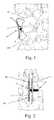
- FIG. 1is a postero-lateral view of a portion of the spine with one example of a spinous process fixation system according to one embodiment of the present invention implanted on adjacent spinous processes;
- FIG. 2is a posterior view of the spinous process fixation system implanted on adjacent spinous processes as shown in FIG. 1 ;
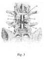
- FIG. 3is a posterior view of the spinous process fixation system of FIG. 1 implanted on adjacent spinous processes used in conjunction with a fusion implant;
- FIG. 4is an exploded view of the spinous process fixation system of FIG. 1 ;
- FIGS. 5-6are perspective views of the assembled spinous process fixation system of FIG. 4 ;
- FIGS. 7-8are perspective and plan views, respectively, of the spinous process fixation system of FIG. 4 in a second, compressed position;
- FIGS. 9-10are top and bottom plan views, respectively, of a first plate forming part of the spinous process fixation system of FIG. 4 ;
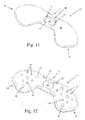
- FIGS. 11-12are top and bottom perspective views, respectively, of the first plate of FIG. 9 ;
- FIG. 13is a side plan view of the first plate of FIG. 9 ;
- FIGS. 14-15are top and bottom plan views, respectively, of a second plate forming part of the spinous process fixation system of FIG. 4 ;
- FIGS. 16-17are top and bottom perspective views, respectively, of the second plate of FIG. 14 ;
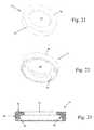
- FIGS. 18-20are perspective, top plan, and side views, respectively, of an example of a locking element forming part of the spinous process fixation system of FIG. 4 ;
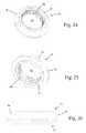
- FIGS. 21-23are top perspective, bottom perspective, and side cross-sectional views, respectively, of an example of a compression member forming part of the spinous process fixation system of FIG. 4 ;
- FIGS. 24-26are top perspective, bottom perspective, and side plan views, respectively, of an example of a locking cap forming part of the spinous process fixation system of FIG. 4 ;
- FIGS. 27-29are perspective, plan, and perspective views, respectively, of an example of a lock nut forming part of the spinous process fixation system of FIG. 4 ;
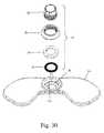
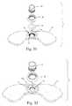
- FIGS. 30-34are various views of a process of assembling a second plate assembly forming part of the spinous process fixation system of FIG. 4 ;
- FIGS. 35-36are perspective and plan views, respectively, of one example of a coupling element forming part of the spinous process fixation system of FIG. 4 ;
- FIG. 37is a plan view of the head region of the coupling element of FIG. 35 ;
- FIG. 38is a cross-sectional view of the second plate assembly of FIG. 34 coupled to the coupling element of FIG. 35 ;
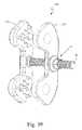
- FIG. 39is a perspective view of an example of a spinous process fixation system according to a second embodiment of the present invention.
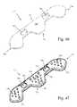
- FIGS. 40-41are top and bottom plan views, respectively, of an example of a first plate forming part of the spinous process fixation system of FIG. 39 ;
- FIGS. 42-43are top and bottom plan views, respectively, of an example of a second plate forming part of the spinous process fixation system of FIG. 39 ;
- FIGS. 44-45are perspective views of an example of a spinous process fixation system according to a third embodiment of the present invention.
- FIGS. 46-48are top perspective, bottom perspective, and bottom plan views, respectively, of an example of a first plate forming part of the spinous process fixation system of FIG. 44 ;
- FIGS. 49-51are bottom plan, top perspective, and bottom perspective views, respectively, of an example of a second plate forming part of the spinous process fixation system of FIG. 44 ;
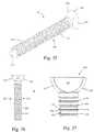
- FIG. 52is a plan view of one example of an insertion device configured for use with the spinous process fixation system of FIG. 4 ;
- FIGS. 53-55are perspective views of steps in a process of engaging the insertion device of FIG. 52 with the spinous process fixation system of FIG. 4 ;
- FIG. 56is a perspective view of a portion of the proximal end of the insertion device of FIG. 52 .
- FIGS. 1-3illustrate an example of a spinous process fixation system 10 according to one embodiment of the present invention attached to adjacent spinous processes SP 1 , SP 2 of a spine.
- the spinous process fixation system 10includes a first plate 12 , a second plate 14 , a coupling element 16 , and a locking assembly 18 ( FIG. 3 ).
- the spinous process fixation system 10is designed to be attached to adjacent spinous processes SP 1 , SP 2 of the spine for immobilizing the adjacent spinous processes SP 1 , SP 2 to promote fusion therebetween.
- the system 10may be used alone (that is, without any supplemental fusion devices, such as interbody fusion implants) as shown in FIGS. 1-2 .
- the system 10may be used with supplemental devices, for example such as a fusion implant 20 ( FIG. 3 ).
- a fusion implant 20FIG. 3
- the system 10allows fusion to occur between the adjacent spinous processes SP 1 , SP 2 by maintaining them in an immobilized, locked relationship such that a boney bridge can form therebetween.
- the formation of the fusion bridge between the adjacent spinous processes SP 1 , SP 2may be augmented or facilitated by placing fusion-enhancing compounds between the spinous processes (such as, e.g.
- allograft boneincluding but not limited to allograft bone, autograft bone, bone morphogenic protein (BMP), calcium hydroxyapatite, demineralized bone matrix, collagen bone graft matrix (e.g. Formagraft®), and stem cell material (e.g. Osteocel®) and/or any number of suitable biomaterials.
- BMPbone morphogenic protein
- demineralized bone matrixe.g. Formagraft®
- stem cell materiale.g. Osteocel®
- FIG. 4illustrates the spinous process fixation system 10 in exploded view.
- the spinous process fixation system 10includes a first plate 12 , a second plate 14 , a coupling element 16 , and a locking assembly 18 .
- the locking assembly 18includes a locking element 22 , compression member 24 , locking cap 26 , and lock nut 28 .
- the locking assembly 18is configured to be assembled with the second plate 14 and provides secure coupling of the coupling member, which in turn maintains the first and second plates 12 , 14 in a desired orientation relative to one another.
- FIGS. 5 and 6illustrate the spinous process fixation system 10 in an assembled but pre-compressed state.
- the spinous process fixation system 10may be provided to the user in such an orientation, with the first and second plates 12 , 14 separated by a predetermined distance (e.g. sufficient to allow for a disposition of the spinous processes SP 1 , SP 2 between the plates 12 , 14 ).
- the locking assembly 18is coupled to the second plate 14
- the first and second plates 12 , 14are coupled by coupling element 16 .
- coupling element 16may be temporarily fixed to the first plate 12 by at least one spot welding 30 . Spot welding 30 further helps keep the first and second plates 12 , 14 in a desired orientation relative to one another prior to implantation of the spinous process fixation system 10 within the spinal column.
- FIGS. 7 and 8illustrate the spinous process fixation system 10 in a compressed state.
- the plates 12 , 14may be compressed to a separation of any desirable distance, however, the distance will be controlled by the width of at least one of the spinous processes SP 1 , SP 2 that are to be fixed using the spinous process fixation system 10 .
- a distal portion of the shaft 122 of the coupling element 16protrudes beyond the profile of the plating system 10 . This distal portion may be left intact, or in the alternative may be removed using an appropriate cutting device (not shown).
- the first plate 12includes a central body portion 32 extending between a pair of end portions 34 , 36 .
- the first plate 12further includes a first surface 38 dimensioned to face medially, or toward the second plate 14 when assembled and a second surface 40 dimensioned to face laterally, or away from the second plate 14 when assembled.
- the central body portion 32may have a generally curved perimeter and (as best viewed in FIGS. 9-10 ) has a width less than the width of the end portions 34 , 36 .
- the increased width of the end portions 34 , 36is designed to present a relatively large footprint on the adjacent spinous processes SP 1 , SP 2 , which helps in establishing a robust engagement therewith while avoiding protrusion beyond the spinous processes SP 1 , SP 2 .
- the end portions 34 , 36may be provided in any number of suitable shapes including but not limited to generally rectangular, generally triangular, and generally rounded. As shown in FIG. 10 , this engagement may be augmented through the use of a plurality of major and minor spike elements 42 , 44 , respectively, disposed on the first surface 38 of the first plate 12 , at the end portions 34 , 36 .
- spike elements 42 , 44are designed to become embedded in the lateral surface of the spinous processes SP 1 , SP 2 when the spinous process fixation system 10 is compressed in place as shown in FIGS. 1-3 .
- the spike elements 42 , 44are provided in an arrangement complimentary to that of the spike elements 64 , 66 of the second plate 14 to increase purchase within the spinous process bone.
- the first plate 12includes a central aperture 46 dimensioned to receive a proximal end 132 of the coupling element 16 . More specifically, as best shown in FIGS. 9 and 11 , the central aperture 46 is a “truncated spherical” recess having straight sides 48 and semi-spherical end regions 50 . The straight sides 48 and semi-spherical end regions 50 are dimensioned to receive the generally straight sides 126 and semi-spherical end regions 128 of the head 120 of the coupling element 16 ( FIGS. 35-37 ).
- the first plate 12also, according to one embodiment, includes elongated recesses 52 formed within first surface 38 and positioned on either side of the central aperture 46 .
- Each recess 52is dimensioned to receive an extension element of an insertion tool, for example such as inserter 400 shown and described below in relation to FIGS. 52-56 .
- the insertion toolmay be used to hold and manipulate the first plate 12 as needed to properly position it on the desired spinous processes SP 1 , SP 2 .
- the first plate 12may be constructed from any of a variety to suitable materials without departing from the scope of the invention, including but not limited to titanium, polymeric materials (e.g. plastics such as poly-ether-ether-ketone) carbon fiber, and/or any other biologically acceptable material.
- the first plate 12may also be provided with any number of suitable dimensions without departing from the scope of the invention.
- the width of the central body portion 32may range from 5 mm to 20 mm
- the width of the end portions 34 , 36may range from 7.5 mm to 25 mm
- the length of the central body portion 32may range from 1 mm to 65 mm
- the length of the end portions 34 , 36may range from 7.5 mm to 25 mm
- the thickness of the first plate 12may range from 1.5 mm to 15 mm. It will be appreciated, however, that these dimensions are provided as examples of those that may be employed with the spinous process fixation system 10 of the present invention and any number of suitable modifications may be made depending upon a variety of factors without departing from the scope of the invention.
- the second plate 14includes similar general features as the first plate 12 .
- the second plate 14includes a central body portion 54 extending between end portions 56 , 58 .
- the second plate 14further includes a first surface 60 dimensioned to face medially, or toward the first plate 12 when assembled and a second surface 62 dimensioned to face laterally, or away from the first plate 12 when assembled.
- the central body portion 54has a generally curved perimeter and (as best viewed in FIGS. 14-15 ) has a width less than the width of the end portions 56 , 58 .
- the increased width of the end portions 56 , 58is designed to present a relatively large footprint on the adjacent spinous processes SP 1 , SP 2 , which helps in establishing a robust engagement therewith while avoiding protrusion beyond the spinous processes SP 1 , SP 2 .
- the end portions 56 , 58may be provided in any number of suitable shapes including but not limited to generally rectangular, generally triangular, and generally rounded. As shown in FIGS. 15 and 17 , this engagement may be augmented through the use of a plurality of major and minor spike elements 64 , 66 disposed on the medial facing surface of the end portions 56 , 58 .
- spike elements 64 , 66are designed to become embedded in the lateral surface of the spinous processes SP 1 , SP 2 when the spinous process fixation system 10 is compressed in place as shown in FIGS. 1-3 .
- the spike elements 64 , 66are provided in an arrangement complimentary to that of the spike elements 42 , 44 of the first plate 12 to increase purchase within the spinous process bone. For example, when the first and second plates 12 , 14 are attached to the bone as shown in FIG. 1 , major spike elements 42 on first plate 12 will be aligned with minor spike elements 66 on second plate 14 , and major spike elements 64 on second plate 14 will be aligned with minor spike elements 44 on first plate 12 so as to minimize the potential for opposing spike elements to contact one another when fully inserted.
- the second plate 14includes a central aperture 68 dimensioned to receive a distal end of the coupling element 16 as shown in FIGS. 1-3 . More specifically, as best viewed in FIGS. 14 and 16 , the central aperture 68 is included within a recess 70 formed within the second surface 62 of the second plate 14 .
- the recess 70is dimensioned to receive the assembled locking assembly 18 . More specifically, as will be described in further detail below, the recess 70 is dimensioned to receive the locking element 22 , a compression member 24 , a portion of the locking cap 26 , and at least a portion of the lock nut 28 .
- the second plate 14includes a rectangular boss anti-rotation feature 72 .
- the anti-rotation feature 72is dimensioned to be received with a corresponding elongated recess 130 ( FIG. 35 ) in coupling element 16 . This feature limits and/or prevents the rotation of the first plate 12 and second plate 14 relative to each other about the axis of the coupling element 16 before, during, and after implantation.
- the second plate 14further includes a pair of elongated recesses 74 formed within the first surface 60 and positioned on either side of the central aperture 68 .
- Each elongated recess 74is dimensioned to receive an extension element of an insertion tool, for example such as inserter 400 shown and described below in relation to FIGS. 52-56 .
- the insertion toolmay be used to hold and manipulate the second plate 14 as needed to properly position it on the desired spinous processes SP 1 , SP 2 .
- the second plate 14may be constructed from any of a variety to suitable materials without departing from the scope of the invention, including but not limited to titanium, polymeric materials (e.g. plastics) carbon fiber, and/or any other biologically acceptable material.
- the second plate 14may also be provided having any number of suitable dimensions without departing from the scope of the invention.
- the width of the central body 54 portionmay range from 5 mm to 20 mm
- the width of the end portions 56 , 58may range from 7.5 mm to 25 mm
- the length of the central body portion 54may range from 1 mm to 65 mm
- the length of the end portions 56 , 58may range from 7.5 mm to 25 mm
- the thickness of the second plate 14may range from 1.5 mm to 15 mm. It will be appreciated, however, that these dimensions are provided as examples of those that may be employed with the spinous process fixation system 10 of the present invention and any number of suitable modifications may be made depending upon a variety of factors without departing from the scope of the invention.
- FIGS. 18-20illustrate one example of a locking element 22 forming part of the locking assembly 18 according to one embodiment of the present invention.
- locking element 22is provided as a generally circular canted coil ring member 76 dimensioned to be received within the recess 70 of the second plate 14 .
- the locking element 22may be defined as having an outer circumference 78 , an inner circumference 80 and an aperture 82 bounded by the inner circumference 80 . Due to the canted coil nature of the locking element 22 , each of the circumferences 78 , 80 are independently variable.
- the outer circumference 78when inserted into the recess 70 of second plate 14 , the outer circumference 78 may correspond to the rigid circumference of the recess 70 .
- the inner circumference 80may expand to accommodate passage of the ridges 134 of the coupling element 16 (described in further detail below).
- This expansion of the inner circumference 80occurs independently from the outer circumference 78 (for example unlike what would occur with a solid snap ring), and thus may occur without any expansion of the outer circumference 78 , which is prevented from expanding by the limits of the recess 70 and compression member 24 .
- This independent expansion of the inner circumference 80occurs due to the canted nature of the coils (best viewed in FIG.
- the force exerted by the ridges 134does not cause purely radial expansion of the locking element 22 , but rather the elastic nature of the coils allow the individual coils to be deformed, thus temporarily expanding the inner circumference 80 to allow for passage of the coupling element 16 therethrough.
- the locking element 22may be have any number suitable sizes, both of the individual rings and of the outer and inner circumferences 78 , 80 , respectively.
- the locking element 22may be formed of any suitable biocompatible material, including but not limited to metal. According to a preferred embodiment, in use the locking element 22 is provided within recess 70 of second plate 14 prior to insertion during the surgical procedure, as part of the locking assembly 18 .
- FIGS. 21-23illustrate one example of a compression cap 24 forming part of the locking assembly 18 according to one embodiment of the present invention.
- the compression cap 24is an annular member dimensioned to be received within the recess 70 of second plate 14 .
- the compression cap 24has a generally planar top surface 84 , a smooth annular side surface 86 , and a central aperture 88 formed in the middle of the compression cap 24 .
- the compression cap 24further includes a conical surface 90 forming at least a portion of the interior of the central aperture 88 .
- the compression cap 24is sized such that the annular side surface 86 snugly engages the interior of the recess 70 of the second plate 14 .
- the aperture 88is sized to allow passage of the coupling element therethrough.
- the conical surface 90is dimensioned to engage the locking element 22 and urge the canted coil ring member 76 to “flatten” in one direction, which allows for insertion of the coupling element 16 therethrough while preventing the removal of the coupling element 16 in the opposite direction. This essentially allows for unidirectional translation of the coupling element 16 relative to the second plate 14 while the locking assembly 18 is in place.
- FIGS. 24-26illustrate one example of a locking cap 26 forming part of the locking assembly 18 according to the present invention.
- the locking cap 26is an annular member having an upper portion 92 , a lower portion 94 , and a central aperture 96 extending therethrough.
- the upper portion 92includes a generally rounded first surface 98 which forms part of the outer perimeter of the spinous process fixation system 10 .
- the rounded nature of the first surface 98helps ensure smooth external surfaces that are unlikely to “catch” on neighboring body tissue.
- the lower portion 94has a circumference that this less than the circumference of the upper portion 92 , and generally corresponding to the circumference of the recess 70 of the second plate 14 .
- the central aperture 96includes a threaded region 100 dimensioned to interact with the threaded region 108 on the lock nut 28 , described in further detail below.
- FIGS. 27-29illustrate one example of a lock nut 28 forming part of the locking assembly 18 according to the present invention.
- the lock nut 28includes a lower portion 102 comprising a distal end, an upper portion 104 comprising a proximal end, and a central aperture 106 extending through the lock nut 28 from upper portion 104 to the lower portion 102 .
- the lower portion 102is generally cylindrical and includes a threaded region 108 dimensioned to threadedly engage with the threaded region 100 on the locking cap 26 . Described in further detail below, this threaded engagement ensures sufficient force is being applied to the compression cap 24 to maintain the locking element 22 in a “flattened” state.
- the upper portion 104includes a plurality of generally curved surfaces 110 interrupted by a plurality of generally planar surface 112 to form an engagement region for a removal tool (not shown).
- the lower portion 102 of the lock nut 28When fully assembled, the lower portion 102 of the lock nut 28 will be almost fully, if not fully received within the central aperture 96 of the locking cap 26 . The upper portion 204 will thus be exposed to the exterior of the construct.
- the lock nut 28is an essential feature for the removal and/or repositioning of the spinous process fixation system 10 .
- the coupling element 16When the lock nut 28 is fully engaged, the coupling element 16 will not be able to be removed from the system 10 due to the “flattened” state of the locking element 22 .
- the lock nut 28is rotated in a counter-clockwise direction (after engaging the upper portion 104 with an appropriate removal tool) to back the lock nut 28 out of the central aperture 96 of the locking cap 26 .
- the locking element 22allows for bi-directional translation of the coupling element 16 relative to the second plate 14 , thus allowing for removal of the coupling element 16 . This may be necessary, for example, should the surgeon determine that the spinous process fixation system 10 needs to be adjusted or removed altogether.
- FIGS. 30-34illustrate the sequential assembly of the locking assembly 18 and the second plate 14 .
- the first stepis to place the locking element 22 within the recess 70 of the second plate 14 , as shown in FIG. 31 .
- the outer circumference 78 ( FIG. 19 ) of the locking element 22should be comfortably flush against the inner annular wall 114 of the recess 70 .
- the second stepis the insertion of the compression cap 24 into the recess 70 .
- the annular side surface 86 of the compression cap 24should have a circumference approximately corresponding to the circumference of the recess 70 such that the compression cap 24 is comfortably flush against the inner annular wall 114 of the recess 70 .
- the conical surface 90 ( FIG. 20 ) of the compression cap 24is resting atop the locking element 22 .
- the third stepis the placement of the locking cap 26 over the recess 70 .
- the locking cap 26is dimensioned such that the lower portion 94 is comfortably flush against the inner annular wall 114 of the recess 70 , and the upper portion 98 sits outside the recess 70 . It is important to note that the lower portion 94 does not contact the compression cap 24 , but rather there is a space 116 ( FIG. 38 ) between the lower portion 94 and the compression cap 24 . This space enables the compression cap 24 to be “loosened” such that the locking element 22 returns to its “relaxed” state to enable removal of the coupling element 16 .
- the locking cap 26may be rigidly attached to the second plate 14 , for example through adhesive, welding, or a threaded engagement (not shown). Alternatively, the locking cap 26 may be provided with a more temporary engagement feature, for example such as a friction fit, to secure the locking cap 26 to the second plate 14 . Securement of the locking cap 26 to the second plate 14 ensures that the compression cap 24 and locking element 22 remain within the recess 70 during removal of the coupling element 16 and potential repositioning of the spinous process fixation system 10 .
- insertion of the lock nut 28is the final step in the coupling of the locking assembly 18 with the second plate 14 .
- the threaded region 108 of the lock nut 28interacts with the threaded region 100 of the locking cap 26 to enable the lock nut 28 to apply a force to the compression cap 24 .
- the lock nut 28is rotated in a clockwise direction and threaded onto the locking cap 26 until the distal end region 118 ( FIG. 38 ) contacts the compression cap 24 .
- FIGS. 35-37illustrate an example of a coupling element 16 according to one embodiment of the present invention.
- the coupling element 16is a ridged bolt having a “truncated spherical” shaped head 120 and a shaft 122 extending therefrom with a ridged portion 124 .
- the shaft 122 of the coupling element 16is dimensioned to be passed through the central aperture 46 of the first plate 12 and then onward through the central aperture 68 of the second plate 14 to the point where the ridged portion 124 matingly engages the locking element 22 within the recess 70 of the second plate 14 .
- the truncated spherical head 120 of the coupling element 16will be advanced into the central aperture 46 of the first plate 12 .
- the truncated spherical head 120has a larger diameter than the inner periphery of the central aperture 46 such that the head 120 cannot pass through the aperture 46 but rather cooperates in a “keyed” fashion with the central aperture 46 .
- straight sides 126 and semi-spherical portions 128 of the head 120cooperate with the straight sides 48 and semi-spherical end regions 50 , respectively, of the aperture 46 .
- central aperture 46may have an oblong-shaped opening to allow for temporary pivoting of the coupling element 16 prior to final tightening of the spinous process fixation system 10 .
- the coupling element 16will thus couple the first plate 12 to the second plate 14 as the bolt 16 is advanced axially into engagement with the locking element 22 within the second plate 14 .
- the locking element 22is dimensioned such that the ridges 124 of the coupling element 16 pass relatively easily through the aperture 68 towards the second surface 62 of the second plate 14 but relatively difficulty in the opposite direction. In this manner, the first plate 12 and second plate 14 will be coupled in a secure manner on adjacent sides of the spinous processes SP 1 , SP 2 . Any of a variety of tools may be used to remove the coupling element 16 from engagement with the locking element 22 so as to disengage the first plate 12 from the second plate 14 .
- the coupling element 16may be provided as being rigidly (and immovably) attached to the second plate 14 .
- thismay be accomplished by using at least one, and preferably two, spot welds 30 ( FIG. 5 ) to temporarily rigidly attach the coupling element 16 to the first plate 12 .
- the spot welds 30may be broken, allowing the coupling element 16 to pivot freely (and unattached) within the central aperture 46 due to the interaction between the truncated spherical shaped head 120 and semi-spherical end regions 50 of the central aperture 46 ( FIG. 11 ).
- the coupling element 16further includes an elongated recess 130 extending substantially the length of the shaft 122 and terminating at the distal end 132 of the coupling element 16 .
- the elongated recess 130has a shape dimension generally corresponding to the shape of the anti-rotation feature 72 of the second plate 14 . As previously mentioned this feature limits and/or prevents the rotation of the first plate 12 and second plate 14 relative to each other about the axis of the coupling element 16 before, during, and after implantation.
- the elongated nature of the recess 130allows for translation of the anti-rotation feature 72 within the recess 130 while the coupling element 16 is advanced or retreated from second plate 14 .
- the ridged portion 124 of the shaft 122includes a plurality of ridges 134 that interact with the locking element 22 to control the translation of the coupling element 16 . More specifically, when the locking assembly 18 is in position, the ridges 134 and coupling element 22 cooperate to allow only unidirectional translation of the coupling element 16 (e.g. in a medial direction to effect compression of the first and second plates 12 , 14 against the spinous processes SP 1 , SP 2 ). The shape of the ridges 134 facilitate this unidirectional feature. Specifically, each ridge 134 has a leading surface 136 that is outwardly beveled (toward head 120 ) from the shaft 122 .
- Each ridge 134further has a trailing upwardly facing surface 138 that extends generally perpendicularly from the shaft 122 to a location where it meets the leading surface 136 . It is important to note that the trailing surface may not be inwardly beveled toward the head 120 because then the unidirectional translation functionality of the construct may be diminished.
- the ridges 134are spaced apart along the shaft 122 at a predetermined distance generally corresponding to the width of the locking element 22 such that a portion of the locking element 22 will occupy a space between two adjacent ridges 134 upon final tightening of the spinous process fixation system 10 .
- the coupling element 16may be constructed from any of a variety of suitable materials without departing from the scope of the invention, including but not limited to titanium, polymeric materials (e.g. plastics) carbon fiber, and/or any other biologically acceptable material.
- the coupling element 16may also be provided having any number of suitable dimensions without departing from the scope of the invention.
- the width of the coupling element 16may range from 3 mm to 10 mm
- the length of the coupling element 16may range from 15 mm to 50 mm
- the ridged portion 124may range from 5 mm to 47 mm. It will be appreciated, however, that these dimensions are provided as examples of those that may be employed with the spinous process fixation system 10 of the present invention and any number of suitable modifications may be made depending upon a variety of factors without departing from the scope of the invention.
- FIG. 38is a cross-sectional view of a portion of the second plate 14 upon coupling to an assembled locking element 18 and insertion of the coupling element 16 .
- compression member 24when compression member 24 is positioned in place, locking element 22 is deformed such that a portion of the inner circumference 80 extends into the central aperture 68 of the second plate 14 . This will help foster engagement with the ridges 134 of the coupling element 16 .
- the inner circumference 80is deformed as described above and as shown by example in FIG. 38 , allowing for essentially uni-directional movement of the coupling element 16 through the locking element 22 .
- Locking cap 26 and lock nut 28are threadedly engaged to each other and attached to second plate 14 in order to secure the compression member 24 and locking element 22 in place, with sufficient force on the locking element 22 to create the desired deformity described above.
- the lock nut 28 and locking cap 26need only to be loosened and/or removed. This will release the force applied to the compression cap 26 , which will in turn cause the locking element 22 to assume a relaxed state. Once in the relaxed state, the locking element 22 will allow for bi-directional movement of the coupling element 16 . This is due partially to the fact that once the compression cap 26 is relaxed and/or removed, the locking element 22 may retreat further into recess 70 , and partially to the canted coil nature of the locking element 22 as described above.
- FIGS. 39-43illustrate an example of a spinous process fixation system 210 according to a second embodiment of the present invention.
- Spinous process fixation system 210is substantially similar to the spinous process fixation system 10 described above, with the only difference being in the first and second plates 212 , 214 . All other features, including the coupling element 16 and locking assembly 18 (and component parts thereto) are identical to that described above, and thus repeat disclosure has been omitted. It should be understood that any of the components described herein in relation to a specific embodiment of the present invention are interchangeable with any other of the components described in relation to any embodiment.
- Embodiments disclosed hereinare provided by way of example to illustrate all of the features of the present invention without limitation as to the specific combination of features. Consequently, features identical to those previously discussed will be assigned the same reference numbers as set forth above.
- the first plate 212will now be described with specific reference to FIGS. 40-41 .
- the first plate 212includes a central body portion 232 extending between a pair of end portions 234 , 236 .
- the central body portion 250may have a generally curved perimeter and has a width less than the width of the end portions 234 , 236 .
- the increased width of the end portions 234 , 236is designed to present a relatively large footprint on the adjacent spinous processes SP 1 , SP 2 , which helps in establishing a robust engagement therewith while avoiding protrusion beyond the spinous processes SP 1 , SP 2 .
- the end portions 234 , 236may be provided in any number of suitable shapes including but not limited to generally rectangular, generally triangular, and generally rounded.
- This engagementmay be augmented through the use of a plurality of major and minor spike elements 242 , 244 , respectively, disposed on the medial facing surface of the end portions 234 , 236 .
- These spike elements 242 , 244are designed to become embedded in the lateral surface of the spinous processes SP 1 , SP 2 when the system 210 is compressed in place as shown in FIG. 1 .
- the spike elements 242 , 244are provided in an arrangement complimentary to that of the spike elements 264 , 266 of the first plate 212 to increase purchase within the spinous process bone.
- the first plate 212includes a central aperture 224 dimensioned to receive a proximal end 120 of the coupling element 16 ( FIG. 35 ). More specifically, the central aperture 224 is a “truncated spherical” recess having straight sides 227 and semi-spherical end regions 229 . The straight sides 227 and semi-spherical end regions 229 are dimensioned to receive the generally straight sides 126 and semi-spherical end regions 128 of the head 120 of the coupling element 16 ( FIGS. 35-37 ).
- the first plate 212also, according to one embodiment, includes attachment apertures 220 positioned on either side of the central aperture 224 .
- Each aperture 220is dimensioned to receive an extension element of an insertion tool, for example such as inserter 400 shown and described below in relation to FIGS. 52-56 .
- the insertion toolmay be used to hold and manipulate the first plate 212 as needed to properly position it on the desired spinous processes SP 1 , SP 2 .
- the first plate 212may be constructed from any of a variety to suitable materials without departing from the scope of the invention, including but not limited to titanium, polymeric materials (e.g. plastics such as poly-ether-ether-ketone) carbon fiber, and/or any other biologically acceptable material.
- the first plate 212may also be provided with any number of suitable dimensions without departing from the scope of the invention.
- the width of the central body portion 232may range from 5 mm to 20 mm
- the width of the end portions 234 , 236may range from 7.5 mm to 25 mm
- the length of the central body portion 232may range from 1 mm to 65 mm
- the length of the end portions 234 , 236may range from 7.5 mm to 25 mm
- the thickness of the first plate 212may range from 1.5 mm to 15 mm. It will be appreciated, however, that these dimensions are provided as examples of those that may be employed with the spinous process fixation system 210 of the present invention and any number of suitable modifications may be made depending upon a variety of factors without departing from the scope of the invention.
- the second plate 214includes similar general features as the first plate 212 .
- the second plate 214includes a central body portion 254 extending between end portions 256 , 258 .
- the second plate 214further includes a first surface 260 dimensioned to face medially, or toward the first plate 212 when assembled and a second surface 262 dimensioned to face laterally, or away from the first plate 212 when assembled.
- the central body portion 254has a generally curved perimeter and has a width less than the width of the end portions 256 , 258 .
- the increased width of the end portions 256 , 258is designed to present a relatively large footprint on the adjacent spinous processes SP 1 , SP 2 , which helps in establishing a robust engagement therewith while avoiding protrusion beyond the spinous processes SP 1 , SP 2 .
- the end portions 256 , 258may be provided in any number of suitable shapes including but not limited to generally rectangular, generally triangular, and generally rounded. This engagement may be augmented through the use of a plurality of major and minor spike elements 264 , 266 disposed on the medial facing surface of the end portions 256 , 258 .
- spike elements 264 , 266are designed to become embedded in the lateral surface of the spinous processes SP 1 , SP 2 when the spinous process fixation system 210 is compressed in place as shown in FIGS. 1-3 .
- the spike elements 264 , 266are provided in an arrangement complimentary to that of the spike elements 242 , 244 of the first plate 212 to increase purchase within the spinous process bone. For example, when the first and second plates 212 , 214 are attached to the bone as shown in FIG.
- major spike elements 242 on first plate 212will be aligned with minor spike elements 266 on second plate 214
- major spike elements 264 on second plate 214will be aligned with minor spike elements 244 on first plate 212 so as to minimize the potential for opposing spike elements to contact one another when fully inserted. If this were to happen, the overall purchase of the spike elements within the bone may be reduced, leading to an unstable construct.
- Providing complementary opposing major and minor spike elements as shown and described herein by exampleminimizes this risk of “meeting in the middle” of the spinous process bone by ensuring spike elements of differing sizes are inserted into the bone opposite one another. This leads to a more stable construct.
- the second plate 214includes a central aperture 268 dimensioned to receive a distal end of the coupling element 16 as shown in FIGS. 1-3 . More specifically, the central aperture 268 is included within a recess 270 formed within the second surface 262 of the second plate 214 .
- the recess 270is dimensioned to receive the assembled locking assembly 18 . More specifically, as described above in relation to spinous process fixation system 10 , the recess 270 is dimensioned to receive the locking element 22 , a compression member 24 , a portion of the locking cap 26 , and at least a portion of the lock nut 28 .
- the ridged engagement between the coupling element 16 and the locking element 22allows the first plate 12 to be coupled to the second plate 14 .
- the second plate 214includes a rectangular boss anti-rotation feature 272 .
- the anti-rotation feature 272is dimensioned to be received with a corresponding elongated recess 130 ( FIG. 35 ) in coupling element 16 . This feature limits and/or prevents the rotation of the first plate 212 and second plate 214 relative to each other about the axis of the coupling element 16 before, during, and after implantation.
- the second plate 214also, according to one embodiment, includes attachment apertures 220 positioned on either side of the central aperture 268 . Each aperture 220 is dimensioned to receive an extension element of an insertion tool, for example such as inserter 400 shown and described below in relation to FIGS. 52-56 . The insertion tool may be used to hold and manipulate the second plate 214 as needed to properly position it on the desired spinous processes SP 1 , SP 2 .
- the second plate 214may be constructed from any of a variety to suitable materials without departing from the scope of the invention, including but not limited to titanium, polymeric materials (e.g. plastics) carbon fiber, and/or any other biologically acceptable material.
- the second plate 214may also be provided having any number of suitable dimensions without departing from the scope of the invention.
- the width of the central body 254 portionmay range from 5 mm to 20 mm
- the width of the end portions 256 , 258may range from 7.5 mm to 25 mm
- the length of the central body portion 254may range from 1 mm to 65 mm
- the length of the end portions 256 , 258may range from 7.5 mm to 25 mm
- the thickness of the second plate 214may range from 1.5 mm to 15 mm. It will be appreciated, however, that these dimensions are provided as examples of those that may be employed with the spinous process fixation system 210 of the present invention and any number of suitable modifications may be made depending upon a variety of factors without departing from the scope of the invention.
- spinous process fixation system 210The remaining components and features of the spinous process fixation system 210 , including the coupling element 16 and locking assembly 18 (including the locking element 22 , compression cap 24 , locking cap 26 , and lock nut 28 ) are identical to those shown and described in relation to spinous process fixation system 10 , rendering further discussion duplicative and unnecessary. It is to be understood that those components form a part of the example shown in FIGS. 39-43 and the above disclosure is applicable to the currently described embodiment.
- FIGS. 44-51illustrate an example of a spinous process fixation system 310 according to a third embodiment of the present invention.
- Spinous process fixation system 310is substantially similar to the spinous process fixation system 10 described above, with the only difference being in the first and second plates 312 , 314 .
- the spinous process fixation system 310is dimensioned for a multi-level fixation (two levels, in this specific example, meaning that the spinous process fixation system 310 may be used to fix three adjacent spinous processes). All other features, including the coupling element 16 and locking assembly 18 (and component parts thereto) are identical to that described above, and thus repeat disclosure has been omitted. Furthermore, features identical to those previously discussed will be assigned the same reference numbers as set forth above.
- the first plate 12will now be described with specific reference to FIGS. 46-48 .
- the first plate 312includes a central body portion 332 extending between a pair of end portions 334 , 336 .
- the central body portion 332further includes a middle fixation region 333 which has a similar size, shape, and function as the end portions 334 , 336 .
- the first plate 312further includes a first surface 338 dimensioned to face medially, or toward the second plate 314 when assembled and a second surface 340 dimensioned to face laterally, or away from the second plate 314 when assembled.
- the central body portion 332may have a generally curved perimeter and has a width less than the width of the end portions 334 , 336 .
- the increased width of the middle fixation region 333 and end portions 334 , 336is designed to present a relatively large footprint on the adjacent spinous processes SP 1 , SP 2 , SP 3 which helps in establishing a robust engagement therewith while avoiding protrusion beyond the spinous processes SP 1 , SP 2 , SP 3 .
- the end portions 334 , 336may be provided in any number of suitable shapes including but not limited to generally rectangular, generally triangular, and generally rounded.
- This engagementmay be augmented through the use of a plurality of major and minor spike elements 342 , 344 , respectively, disposed on the first surface 338 of the first plate 312 , at the middle fixation region 333 and end portions 334 , 336 .
- These spike elements 342 , 344are designed to become embedded in the lateral surface of the spinous processes SP 1 , SP 2 , SP 3 when the spinous process fixation system 310 is compressed in place.
- the spike elements 342 , 344are provided in an arrangement complimentary to that of the spike elements 364 , 366 of the second plate 314 to increase purchase within the spinous process bone.
- the first plate 312includes a pair of fixation apertures 346 each dimensioned to receive a proximal end 132 of the coupling element 16 . More specifically, the fixation apertures 346 are “truncated spherical” recesses having straight sides 348 and semi-spherical end regions 350 . The straight sides 348 and semi-spherical end regions 350 are dimensioned to receive the generally straight sides 126 and semi-spherical end regions 128 of the head 120 of the coupling element 16 ( FIGS. 35-37 ).
- the fixation apertures 346are positioned on either side of the middle fixation region 333 such that one fixation aperture 346 is between the middle fixation region 333 and the first end portion 334 and one fixation aperture 346 is between the middle fixation region 333 and the second end portion 336 . This alignment is such that the coupling elements 16 will extend through the interspinous process spaces.
- the first plate 312also, according to one embodiment, includes elongated recesses 352 formed within first surface 338 and positioned on either side of the fixation apertures 346 . Each recess 352 is dimensioned to receive an extension element of an insertion tool, for example such as inserter 400 shown and described below in relation to FIGS. 52-56 .
- the insertion toolmay be used to hold and manipulate the first plate 212 as needed to properly position it on the desired spinous processes SP 1 , SP 2 , SP 3 .
- the first plate 312may be constructed from any of a variety to suitable materials without departing from the scope of the invention, including but not limited to titanium, polymeric materials (e.g. plastics such as poly-ether-ether-ketone) carbon fiber, and/or any other biologically acceptable material.
- the first plate 312may also be provided with any number of suitable dimensions without departing from the scope of the invention.
- the width of the central body portion 332may range from 5 mm to 20 mm
- the width of the end portions 334 , 336may range from 7.5 mm to 25 mm
- the length of the central body portion 332may range from 1 mm to 65 mm
- the length of the end portions 334 , 336may range from 7.5 mm to 25 mm
- the thickness of the first plate 312may range from 1.5 mm to 15 mm. It will be appreciated, however, that these dimensions are provided as examples of those that may be employed with the spinous process fixation system 310 of the present invention and any number of suitable modifications may be made depending upon a variety of factors without departing from the scope of the invention.
- the second plate 314includes similar general features as the first plate 312 .
- the second plate 314includes a central body portion 354 extending between end portions 356 , 358 .
- the central body portion 354further includes a middle fixation region 355 which has a similar size, shape, and function as the end portions 356 , 358 .
- the second plate 314further includes a first surface 360 dimensioned to face medially, or toward the first plate 312 when assembled and a second surface 362 dimensioned to face laterally, or away from the first plate 312 when assembled.
- the central body portion 354has a generally curved perimeter and has a width less than the width of the end portions 356 , 358 .
- the increased width of the middle fixation region 355 and end portions 356 , 358is designed to present a relatively large footprint on the adjacent spinous processes SP 1 , SP 2 , SP 3 which helps in establishing a robust engagement therewith while avoiding protrusion beyond the spinous processes SP 1 , SP 2 , SP 3 .
- This engagementmay be augmented through the use of a plurality of major and minor spike elements 364 , 366 disposed on the medial facing surface of the middle fixation region 355 and end portions 356 , 358 .
- These spike elements 364 , 366are designed to become embedded in the lateral surface of the spinous processes SP 1 , SP 2 when the spinous process fixation system 310 is compressed in place.
- the spike elements 364 , 366are provided in an arrangement complimentary to that of the spike elements 342 , 344 of the first plate 312 to increase purchase within the spinous process bone.
- major spike elements 342 on first plate 312will be aligned with minor spike elements 366 on second plate 314
- major spike elements 364 on second plate 314will be aligned with minor spike elements 344 on first plate 312 so as to minimize the potential for opposing spike elements to contact one another when fully inserted. If this were to happen, the overall purchase of the spike elements within the bone may be reduced, leading to an unstable construct.
- Providing complementary opposing major and minor spike elements as shown and described herein by exampleminimizes this risk of “meeting in the middle” of the spinous process bone by ensuring spike elements of differing sizes are inserted into the bone opposite one another. This leads to a more stable construct.
- the second plate 314includes a pair of fixation apertures 368 dimensioned to receive a distal end 132 of the coupling element 16 . More specifically, the fixation apertures 368 are each included within recesses 370 formed within the second surface 362 of the second plate 314 .
- the recesses 370are positioned between the middle fixation region 355 and each of the first and second end portions 356 , 358 and are dimensioned to receive the assembled locking assembly 18 . More specifically, as described above, the recesses 370 are dimensioned to receive the locking element 22 , a compression member 24 , a portion of the locking cap 26 , and at least a portion of the lock nut 28 .
- the second plate 314includes a rectangular boss anti-rotation feature 372 .
- the anti-rotation feature 372is dimensioned to be received with a corresponding elongated recess 130 ( FIG. 35 ) in coupling element 16 . This feature limits and/or prevents the rotation of the first plate 312 and second plate 314 relative to each other about the axis of the coupling element 16 before, during, and after implantation.
- the second plate 314further includes two pair of elongated recesses 374 formed within the first surface 360 and positioned on either side of the fixation apertures 368 .
- Each elongated recess 374is dimensioned to receive an extension element of an insertion tool, for example such as inserter 400 shown and described below in relation to FIGS. 52-56 .
- the insertion toolmay be used to hold and manipulate the second plate 314 as needed to properly position it on the desired spinous processes SP 1 , SP 2 , SP 3 .
- the second plate 314may be constructed from any of a variety to suitable materials without departing from the scope of the invention, including but not limited to titanium, polymeric materials (e.g. plastics) carbon fiber, and/or any other biologically acceptable material.
- the second plate 314may also be provided having any number of suitable dimensions without departing from the scope of the invention.
- the width of the central body 354 portionmay range from 5 mm to 20 mm
- the width of the end portions 356 , 358may range from 7.5 mm to 25 mm
- the length of the central body portion 354may range from 1 mm to 65 mm
- the length of the end portions 356 , 358may range from 7.5 mm to 25 mm
- the thickness of the second plate 314may range from 1.5 mm to 15 mm. It will be appreciated, however, that these dimensions are provided as examples of those that may be employed with the spinous process fixation system 310 of the present invention and any number of suitable modifications may be made depending upon a variety of factors without departing from the scope of the invention.
- spinous process fixation system 310The remaining components and features of the spinous process fixation system 310 , including the coupling element 16 and locking assembly 18 (including the locking element 22 , compression cap 24 , locking cap 26 , and lock nut 28 ) are identical to those shown and described in relation to spinous process fixation system 10 , rendering further discussion duplicative and unnecessary. It is to be understood that those components form a part of the example shown in FIGS. 44-51 and the above disclosure is applicable to the currently described embodiment.
- FIGS. 52-56illustrate one example of an insertion tool 400 for use with any of the spinous process fixation systems 10 , 210 , 310 described above.
- the insertion tool 400includes first and second elongated members 402 , 404 pivotably coupled together about a pivot point 406 .
- the first elongated member 402includes a proximal handle 408 and a distal implant engagement region 410 .
- the proximal handle 408has a proximal end 412 including a bifurcation 414 for receiving a ratchet arm 420 including a plurality of teeth 421 .
- the second elongated member 404includes a proximal handle 416 and a distal implant engagement region 418 .
- the insertion tool 400further includes a ratchet arm 420 hingedly connected with the handle 416 of the second elongated member 404 at a proximal hinge point 422 .
- the ratchet armfurther includes a lock stop 424 for preventing over compression of the spinous process fixation system 10 prior to implantation into the affected surgical target site.
- the distal implant engagement region 410 of the first elongated member 402includes a first pronged region 426 and a second pronged region 428 .
- the first pronged region 426is dimensioned to engage the second surface 62 of the second plate 14 while avoiding the locking assembly 18 , as shown in FIG. 53 .
- the second pronged region 428is dimensioned to engage the first surface 60 of the second plate 12 while avoiding the coupling element 16 , as shown in FIG. 54 .
- the second pronged region 428includes a plurality of tanged tips 430 dimensioned to be received within the elongated recesses 74 of the second plate 14 , enabling the inserter 400 to grab the second plate 14 .
- the distal implant engagement region 418 of the second elongated member 404includes a generally rounded engagement feature 432 configured to engage the first plate 12 . More specifically, the engagement feature 432 is dimensioned to seat at least partially in the aperture 46 of the first plate 12 .
- the distal implant engagement region 418further includes a post 434 extending generally perpendicularly from the engagement region 418 .
- FIGS. 53-55illustrate the steps involved in using the inserter 400 to controllably capture the spinous process fixation system 10 in advance of implanting it into a surgical target site.
- the distal implant engagement region 410 of the first elongated member 402is positioned such that it engages the second plate 14 .
- the distal implant engagement region 418 of the second elongated member 404is positioned such that it engages the first plate 12 .
- the handles 408 , 418are squeezed together to create a compressive force on the spinous process fixation system 10 .
- the ratchet arm 420functions to maintain the compressive force on the spinous process fixation system 10 through implantation so that it does not dislodge from the inserter 400 .
- the ratchet arm 420is provided with a lock stop 424 . As illustrated in FIG. 56 , the lock stop 424 will halt advancement of the handle 408 past a certain point to prevent this over compression.
- the ratchet arm 420can be pivoted away from the handle 408 so that the lock stop 424 is no longer engaged. This will allow the user to squeeze the handle further to employ enough force to fully seat the spinous process fixation system 10 onto the spinous processes. Once this has happened, the operative corridor may be closed and the procedure is concluded.
- the embodiments described hereinare intended to rigidly fix two spinous processes relative to one another.
- the spinous process fixation system 10may be implanted via a traditional “open” procedure or a minimally invasive procedure.
- the spinous process fixation system 10may be implanted generally posteriorly through a single incision (e.g. where the first plate 12 and second plate 14 are passed through the same incision) or multiple incisions (e.g. where the first plate 12 is passed through one incision and the second plate 14 is passed through a second incision).
- the surgeonmay pass both the first plate 12 and the second plate 14 into position on either side of adjacent spinous processes SP 1 , SP 2 at the same time.
- the surgeonmay first insert the first plate 12 to engage one side of the spinous processes SP 1 , SP 2 and then insert the second plate 14 against the other side of spinous processes SP 1 , SP 2 .
- the surgeoncan adjust the position of the end portions of the first plate 12 and second plate 14 so that the spike members are engaged into the spinous processes SP 1 , SP 2 .
- compression instrumentationmay be applied to press the plates toward each other, whereupon the spikes enter the spinal processes SP 1 , SP 2 .
- the coupling element 16is tightened using any number of suitable instruments.
Landscapes
- Health & Medical Sciences (AREA)
- Orthopedic Medicine & Surgery (AREA)
- Life Sciences & Earth Sciences (AREA)
- Neurology (AREA)
- Surgery (AREA)
- Heart & Thoracic Surgery (AREA)
- Engineering & Computer Science (AREA)
- Biomedical Technology (AREA)
- Nuclear Medicine, Radiotherapy & Molecular Imaging (AREA)
- Medical Informatics (AREA)
- Molecular Biology (AREA)
- Animal Behavior & Ethology (AREA)
- General Health & Medical Sciences (AREA)
- Public Health (AREA)
- Veterinary Medicine (AREA)
- Prostheses (AREA)
- Surgical Instruments (AREA)
Abstract
Description
Claims (15)
Priority Applications (1)
| Application Number | Priority Date | Filing Date | Title |
|---|---|---|---|
| US12/412,354US8343190B1 (en) | 2008-03-26 | 2009-03-26 | Systems and methods for spinous process fixation |
Applications Claiming Priority (3)
| Application Number | Priority Date | Filing Date | Title |
|---|---|---|---|
| US3976108P | 2008-03-26 | 2008-03-26 | |
| US12378308P | 2008-04-11 | 2008-04-11 | |
| US12/412,354US8343190B1 (en) | 2008-03-26 | 2009-03-26 | Systems and methods for spinous process fixation |
Publications (1)
| Publication Number | Publication Date |
|---|---|
| US8343190B1true US8343190B1 (en) | 2013-01-01 |
Family
ID=47388229
Family Applications (1)
| Application Number | Title | Priority Date | Filing Date |
|---|---|---|---|
| US12/412,354Active2031-01-12US8343190B1 (en) | 2008-03-26 | 2009-03-26 | Systems and methods for spinous process fixation |
Country Status (1)
| Country | Link |
|---|---|
| US (1) | US8343190B1 (en) |
Cited By (65)
| Publication number | Priority date | Publication date | Assignee | Title |
|---|---|---|---|---|
| US20100241126A1 (en)* | 2006-10-11 | 2010-09-23 | Ignace Ghijselings | Device and method for installing femoral prosthetic knee joint |
| US20110004248A1 (en)* | 2007-02-26 | 2011-01-06 | Samy Abdou | Spinal stabilization systems and methods of use |
| US20110066186A1 (en)* | 2009-09-11 | 2011-03-17 | Boyer Ii Michael Lee | Spinous Process Fusion Devices |
| US20110224731A1 (en)* | 2010-03-12 | 2011-09-15 | Southern Spine, Llc | Interspinous Process Spacing Device |
| US20120109202A1 (en)* | 2010-04-30 | 2012-05-03 | Neuraxis Llc | Intersegmental motion preservation system for use in the spine and methods for use thereof |
| US20120136390A1 (en)* | 2010-11-29 | 2012-05-31 | Butler Michael S | Spinal Implants For Lumbar Vertebra To Sacrum Fixation |
| US20120253396A1 (en)* | 2008-08-08 | 2012-10-04 | Alphatec Spine, Inc. | Spinous process device and method of use |
| US20120290008A1 (en)* | 2010-01-14 | 2012-11-15 | X-Spine Systems, Inc. | Modular interspinous fixation system and method |
| US20120296378A1 (en)* | 2007-04-10 | 2012-11-22 | Life Spine, Inc. | Adjustable spine distraction implant |
| US20120296379A1 (en)* | 2008-02-21 | 2012-11-22 | Zimmer Gmbh | Expandable interspinous process spacer with lateral support and method for implantation |
| US20130090689A1 (en)* | 2011-10-07 | 2013-04-11 | Alan Villavicencio | Spinal fixation device |
| US20130158604A1 (en)* | 2011-06-17 | 2013-06-20 | Bryan Okamoto | Expandable Interspinous Device |
| US20140012260A1 (en)* | 2012-07-09 | 2014-01-09 | The Cleveland Clinc Foundation | Bone fixation assembly |
| US20140277138A1 (en)* | 2013-03-15 | 2014-09-18 | Warsaw Orthopedic, Inc. | Locking mechanism |
| US20140324103A1 (en)* | 2011-12-09 | 2014-10-30 | Spineart Sa | Bone clamping system |
| US8882805B1 (en) | 2011-08-02 | 2014-11-11 | Lawrence Maccree | Spinal fixation system |
| US8940048B2 (en) | 2005-03-31 | 2015-01-27 | Life Spine, Inc. | Expandable spinal interbody and intravertebral body devices |
| US20150066087A1 (en)* | 2009-09-11 | 2015-03-05 | Globus Medical, Inc | Spinous Process Fusion Devices |
| US20150066086A1 (en)* | 2012-05-11 | 2015-03-05 | Aesculap Ag | Implant for stabilizing spinous processes |
| US9034041B2 (en) | 2005-03-31 | 2015-05-19 | Life Spine, Inc. | Expandable spinal interbody and intravertebral body devices |
| US20160015432A1 (en)* | 2014-06-06 | 2016-01-21 | Aurora Spine, Inc. | Polyaxial interspinous fusion implant and bone growth stimulation system |
| US20160045231A1 (en)* | 2014-08-14 | 2016-02-18 | FloSpine LLC | Interspinous fusion device |
| US9301788B2 (en) | 2008-04-10 | 2016-04-05 | Life Spine, Inc. | Adjustable spine distraction implant |
| US9314276B2 (en)* | 2009-03-13 | 2016-04-19 | Spinal Simplicity Llc. | Interspinous process implant and fusion cage spacer |
| WO2016073924A1 (en)* | 2014-11-06 | 2016-05-12 | Spinal Elements, Inc. | Apparatus and method of treating spinous processes |
| USD757943S1 (en) | 2011-07-14 | 2016-05-31 | Nuvasive, Inc. | Spinous process plate |
| US9757165B2 (en) | 2015-10-23 | 2017-09-12 | Warsaw Orthopedic, Inc. | Spinal implant system and method |
| US9757164B2 (en) | 2013-01-07 | 2017-09-12 | Spinal Simplicity Llc | Interspinous process implant having deployable anchor blades |
| US9801733B2 (en) | 2005-03-31 | 2017-10-31 | Life Spine, Inc. | Expandable spinal interbody and intravertebral body devices |
| US20170311993A1 (en)* | 2010-12-13 | 2017-11-02 | Globus Medical, Inc. | Spinous process fusion devices and methods thereof |
| US9861399B2 (en) | 2009-03-13 | 2018-01-09 | Spinal Simplicity, Llc | Interspinous process implant having a body with a removable end portion |
| US9907580B2 (en)* | 2005-11-22 | 2018-03-06 | Bryson Medical Technology Llc | Adjustable spinous process spacer device and method of treating spinal disorders |
| US9987052B2 (en) | 2015-02-24 | 2018-06-05 | X-Spine Systems, Inc. | Modular interspinous fixation system with threaded component |
| US10034693B2 (en) | 2016-07-07 | 2018-07-31 | Mark S. Stern | Spinous laminar clamp assembly |
| US10154911B2 (en) | 2013-03-13 | 2018-12-18 | Life Spine, Inc. | Expandable implant assembly |
| US10335207B2 (en) | 2015-12-29 | 2019-07-02 | Nuvasive, Inc. | Spinous process plate fixation assembly |
| US10383741B2 (en) | 2013-03-13 | 2019-08-20 | Life Spine, Inc. | Expandable spinal interbody assembly |
| US10426632B2 (en) | 2013-03-13 | 2019-10-01 | Life Spine, Inc. | Expandable spinal interbody assembly |
| US10448977B1 (en) | 2012-03-31 | 2019-10-22 | Ali H. MESIWALA | Interspinous device and related methods |
| US10543107B2 (en) | 2009-12-07 | 2020-01-28 | Samy Abdou | Devices and methods for minimally invasive spinal stabilization and instrumentation |
| US10548740B1 (en) | 2016-10-25 | 2020-02-04 | Samy Abdou | Devices and methods for vertebral bone realignment |
| US10575961B1 (en) | 2011-09-23 | 2020-03-03 | Samy Abdou | Spinal fixation devices and methods of use |
| US10695105B2 (en) | 2012-08-28 | 2020-06-30 | Samy Abdou | Spinal fixation devices and methods of use |
| US10857003B1 (en) | 2015-10-14 | 2020-12-08 | Samy Abdou | Devices and methods for vertebral stabilization |
| US10918498B2 (en) | 2004-11-24 | 2021-02-16 | Samy Abdou | Devices and methods for inter-vertebral orthopedic device placement |
| US10973648B1 (en) | 2016-10-25 | 2021-04-13 | Samy Abdou | Devices and methods for vertebral bone realignment |
| US11006982B2 (en) | 2012-02-22 | 2021-05-18 | Samy Abdou | Spinous process fixation devices and methods of use |
| US11033403B2 (en) | 2017-07-10 | 2021-06-15 | Life Spine, Inc. | Expandable implant assembly |
| US11173040B2 (en) | 2012-10-22 | 2021-11-16 | Cogent Spine, LLC | Devices and methods for spinal stabilization and instrumentation |
| US11179248B2 (en) | 2018-10-02 | 2021-11-23 | Samy Abdou | Devices and methods for spinal implantation |
| US11304818B2 (en) | 2013-03-13 | 2022-04-19 | Life Spine, Inc. | Expandable spinal interbody assembly |
| US11311388B2 (en) | 2020-08-20 | 2022-04-26 | Spinal Simplicity, Llc | Interspinous process implant |
| US11382764B2 (en) | 2019-06-10 | 2022-07-12 | Life Spine, Inc. | Expandable implant assembly with compression features |
| US11510710B2 (en) | 2016-04-14 | 2022-11-29 | Spinal Simplicity, Llc | Locking system for interspinous implant insertion instrument |
| US11534310B2 (en) | 2020-08-20 | 2022-12-27 | Spinal Simplicity, Llc | Interspinous process implant |
| US11602440B2 (en) | 2020-06-25 | 2023-03-14 | Life Spine, Inc. | Expandable implant assembly |
| US11602439B2 (en) | 2020-04-16 | 2023-03-14 | Life Spine, Inc. | Expandable implant assembly |
| US11672572B1 (en) | 2022-04-08 | 2023-06-13 | Spinal Simplicity, Llc | Disposable interspinous implant insertion instrument |
| US11857432B2 (en) | 2020-04-13 | 2024-01-02 | Life Spine, Inc. | Expandable implant assembly |
| US11896494B2 (en) | 2017-07-10 | 2024-02-13 | Life Spine, Inc. | Expandable implant assembly |
| US12042395B2 (en) | 2019-06-11 | 2024-07-23 | Life Spine, Inc. | Expandable implant assembly |
| US12133664B2 (en) | 2022-12-13 | 2024-11-05 | Spinal Simplicity, Llc | Medical implant |
| US12193948B2 (en) | 2013-03-13 | 2025-01-14 | Life Spine, Inc. | Expandable implant assembly |
| US12336917B2 (en) | 2020-05-15 | 2025-06-24 | Life Spine, Inc. | Steerable implant assembly |
| US12364610B2 (en) | 2020-09-08 | 2025-07-22 | Life Spine, Inc. | Expandable implant with pivoting control assembly |
Citations (128)
| Publication number | Priority date | Publication date | Assignee | Title |
|---|---|---|---|---|
| US267269A (en) | 1882-11-07 | Nut-lock | ||
| FR1037262A (en) | 1951-05-18 | 1953-09-15 | Improvements to prostheses intended for blocking the sacrolumbar joint | |
| US2677369A (en) | 1952-03-26 | 1954-05-04 | Fred L Knowles | Apparatus for treatment of the spinal column |
| GB780652A (en) | 1954-04-30 | 1957-08-07 | Zimmer Orthopaedic Ltd | Improvements in or relating to apparatus for use in spinal fixation |
| US3025853A (en) | 1958-07-07 | 1962-03-20 | Christopher A Mason | Fixation device for fractured femur |
| US3242922A (en) | 1963-06-25 | 1966-03-29 | Charles B Thomas | Internal spinal fixation means |
| US3426364A (en) | 1966-08-25 | 1969-02-11 | Colorado State Univ Research F | Prosthetic appliance for replacing one or more natural vertebrae |
| US3648691A (en) | 1970-02-24 | 1972-03-14 | Univ Colorado State Res Found | Method of applying vertebral appliance |
| US3805219A (en) | 1973-02-27 | 1974-04-16 | Bendix Corp | Contact removal bushing for electrical connector |
| US4143883A (en) | 1978-02-07 | 1979-03-13 | Controlex Corporation Of America | Push-pull control with spring-loaded seal |
| US4448191A (en) | 1981-07-07 | 1984-05-15 | Rodnyansky Lazar I | Implantable correctant of a spinal curvature and a method for treatment of a spinal curvature |
| DE3114872C2 (en) | 1981-04-13 | 1985-09-12 | Viktor KirilloviČ Krasnojarsk Gupalov | Implant to correct curvatures of the spine |
| US4554914A (en) | 1983-10-04 | 1985-11-26 | Kapp John P | Prosthetic vertebral body |
| US4570618A (en) | 1983-11-23 | 1986-02-18 | Henry Ford Hospital | Intervertebral body wire stabilization |
| US4604995A (en) | 1984-03-30 | 1986-08-12 | Stephens David C | Spinal stabilizer |
| US4643178A (en) | 1984-04-23 | 1987-02-17 | Fabco Medical Products, Inc. | Surgical wire and method for the use thereof |
| US4655462A (en) | 1985-01-07 | 1987-04-07 | Peter J. Balsells | Canted coiled spring and seal |
| US4773402A (en) | 1985-09-13 | 1988-09-27 | Isola Implants, Inc. | Dorsal transacral surgical implant |
| US4913134A (en) | 1987-07-24 | 1990-04-03 | Biotechnology, Inc. | Spinal fixation system |
| US5011484A (en) | 1987-11-16 | 1991-04-30 | Breard Francis H | Surgical implant for restricting the relative movement of vertebrae |
| US5084049A (en) | 1989-02-08 | 1992-01-28 | Acromed Corporation | Transverse connector for spinal column corrective devices |
| US5092866A (en) | 1989-02-03 | 1992-03-03 | Breard Francis H | Flexible inter-vertebral stabilizer as well as process and apparatus for determining or verifying its tension before installation on the spinal column |
| US5167662A (en) | 1992-01-24 | 1992-12-01 | Zimmer, Inc. | Temporary clamp and inserter for a posterior midline spinal clamp |
| US5180393A (en) | 1990-09-21 | 1993-01-19 | Polyclinique De Bourgogne & Les Hortensiad | Artificial ligament for the spine |
| US5261914A (en) | 1987-09-02 | 1993-11-16 | Russell Warren | Surgical fastener |
| US5304178A (en) | 1992-05-29 | 1994-04-19 | Acromed Corporation | Sublaminar wire |
| US5352225A (en) | 1993-01-14 | 1994-10-04 | Yuan Hansen A | Dual-tier spinal clamp locking and retrieving system |
| FR2703239B1 (en) | 1993-03-30 | 1995-06-02 | Brio Bio Rhone Implant Medical | Clip for interspinous prosthesis. |
| US5470333A (en) | 1993-03-11 | 1995-11-28 | Danek Medical, Inc. | System for stabilizing the cervical and the lumbar region of the spine |
| US5496318A (en) | 1993-01-08 | 1996-03-05 | Advanced Spine Fixation Systems, Inc. | Interspinous segmental spine fixation device |
| US5531747A (en) | 1993-03-11 | 1996-07-02 | Danek Medical Inc. | System for stabilizing the spine and reducing spondylolisthesis |
| US5609634A (en) | 1992-07-07 | 1997-03-11 | Voydeville; Gilles | Intervertebral prosthesis making possible rotatory stabilization and flexion/extension stabilization |
| US5645599A (en) | 1994-07-26 | 1997-07-08 | Fixano | Interspinal vertebral implant |
| US5722976A (en) | 1993-08-27 | 1998-03-03 | Brown; Robin Peter | Apparatus and method for surgically securing bone parts |
| US5836948A (en) | 1997-01-02 | 1998-11-17 | Saint Francis Medical Technologies, Llc | Spine distraction implant and method |
| US6048342A (en) | 1997-01-02 | 2000-04-11 | St. Francis Medical Technologies, Inc. | Spine distraction implant |
| US6312431B1 (en) | 2000-04-24 | 2001-11-06 | Wilson T. Asfora | Vertebrae linking system |
| US6364883B1 (en) | 2001-02-23 | 2002-04-02 | Albert N. Santilli | Spinous process clamp for spinal fusion and method of operation |
| FR2806614B1 (en) | 2000-03-21 | 2002-05-31 | Cousin Biotech | FASTENING DEVICE ON THE SACRUM |
| US20030040746A1 (en) | 2001-07-20 | 2003-02-27 | Mitchell Margaret E. | Spinal stabilization system and method |
| US20030065330A1 (en)* | 1998-10-20 | 2003-04-03 | St. Francis Medical Technologies, Inc. | Deflectable spacer for use as an interspinous process implant and method |
| US20030094812A1 (en) | 2001-11-21 | 2003-05-22 | Balsells Peter J. | Connector with radial spring |
| US6582433B2 (en) | 2001-04-09 | 2003-06-24 | St. Francis Medical Technologies, Inc. | Spine fixation device and method |
| US6626944B1 (en) | 1998-02-20 | 2003-09-30 | Jean Taylor | Interspinous prosthesis |
| US6641585B2 (en) | 2000-09-22 | 2003-11-04 | Showa Ika Kohgyo Co., Ltd. | Bone connecting tool and connecting member thereof |
| US20030216736A1 (en) | 2002-05-17 | 2003-11-20 | Robinson James C. | Device for fixation of spinous processes |
| US6652534B2 (en) | 1998-10-20 | 2003-11-25 | St. Francis Medical Technologies, Inc. | Apparatus and method for determining implant size |
| US6652527B2 (en) | 1998-10-20 | 2003-11-25 | St. Francis Medical Technologies, Inc. | Supplemental spine fixation device and method |
| US20030236472A1 (en) | 2002-06-19 | 2003-12-25 | James Van Hoeck | Systems and methods for moving anatomical elements |
| US6695842B2 (en) | 1997-10-27 | 2004-02-24 | St. Francis Medical Technologies, Inc. | Interspinous process distraction system and method with positionable wing and method |
| US6699247B2 (en) | 1997-01-02 | 2004-03-02 | St. Francis Medical Technologies, Inc. | Spine distraction implant |
| US6712819B2 (en) | 1998-10-20 | 2004-03-30 | St. Francis Medical Technologies, Inc. | Mating insertion instruments for spinal implants and methods of use |
| US6761720B1 (en) | 1999-10-15 | 2004-07-13 | Spine Next | Intervertebral implant |
| US6796983B1 (en) | 1997-01-02 | 2004-09-28 | St. Francis Medical Technologies, Inc. | Spine distraction implant and method |
| US20040260291A1 (en) | 2003-06-20 | 2004-12-23 | Jensen David G. | Bone plates with intraoperatively tapped apertures |
| US20050033434A1 (en) | 2003-08-06 | 2005-02-10 | Sdgi Holdings, Inc. | Posterior elements motion restoring device |
| US20050165398A1 (en) | 2004-01-26 | 2005-07-28 | Reiley Mark A. | Percutaneous spine distraction implant systems and methods |
| US20050203624A1 (en) | 2004-03-06 | 2005-09-15 | Depuy Spine, Inc. | Dynamized interspinal implant |
| US20050203512A1 (en) | 2004-03-09 | 2005-09-15 | Depuy Spine, Inc. | Posterior process dynamic spacer |
| US20060036258A1 (en) | 2004-06-08 | 2006-02-16 | St. Francis Medical Technologies, Inc. | Sizing distractor and method for implanting an interspinous implant between adjacent spinous processes |
| US20060036256A1 (en) | 2004-08-03 | 2006-02-16 | Carl Allen L | Spine stabilization device and method |
| US20060064095A1 (en) | 2003-03-07 | 2006-03-23 | Peter Senn | Locking screw for an intramedullary nail |
| US20060106381A1 (en) | 2004-11-18 | 2006-05-18 | Ferree Bret A | Methods and apparatus for treating spinal stenosis |
| US20060106397A1 (en) | 2004-10-25 | 2006-05-18 | Lins Robert E | Interspinous distraction devices and associated methods of insertion |
| US20060136060A1 (en) | 2002-09-10 | 2006-06-22 | Jean Taylor | Posterior vertebral support assembly |
| US20060235532A1 (en) | 2003-01-20 | 2006-10-19 | Abbott Spine | Unit for treatment of the degeneration of an intervertebral disc |
| US20060241601A1 (en) | 2005-04-08 | 2006-10-26 | Trautwein Frank T | Interspinous vertebral and lumbosacral stabilization devices and methods of use |
| US20060247640A1 (en)* | 2005-04-29 | 2006-11-02 | Sdgi Holdings, Inc. | Spinous process stabilization devices and methods |
| US20060247633A1 (en)* | 2004-12-13 | 2006-11-02 | St. Francis Medical Technologies, Inc. | Inter-cervical facet implant with surface enhancements |
| US20060293662A1 (en) | 2005-06-13 | 2006-12-28 | Boyer Michael L Ii | Spinous process spacer |
| US7201775B2 (en) | 2002-09-24 | 2007-04-10 | Bogomir Gorensek | Stabilizing device for intervertebral disc, and methods thereof |
| US20070093825A1 (en) | 2005-09-28 | 2007-04-26 | Nuvasive Inc. | Methods and apparatus for treating spinal stenosis |
| US20070093828A1 (en) | 2005-10-07 | 2007-04-26 | Abdou M S | Devices and methods for inter-vertebral orthopedic device placement |
| US20070093823A1 (en) | 2005-09-29 | 2007-04-26 | Nuvasive, Inc. | Spinal distraction device and methods of manufacture and use |
| US20070100340A1 (en) | 2005-10-27 | 2007-05-03 | Sdgi Holdings, Inc. | Intervertebral prosthetic device for spinal stabilization and method of implanting same |
| US20070173832A1 (en) | 2004-10-20 | 2007-07-26 | Vertiflex, Inc. | Systems and methods for posterior dynamic stabilization of the spine |
| WO2007087535A2 (en) | 2006-01-23 | 2007-08-02 | Pioneer Surgical Technology, Inc. | Interlaminar stabilizing system |
| US7252673B2 (en) | 2003-09-10 | 2007-08-07 | Warsaw Orthopedic, Inc. | Devices and methods for inserting spinal implants |
| US20070225724A1 (en) | 2006-03-24 | 2007-09-27 | Edmond Elizabeth W | Non-pedicle based interspinous spacer |
| US20070233129A1 (en) | 2006-02-17 | 2007-10-04 | Rudolf Bertagnoli | Method and system for performing interspinous space preparation for receiving an implant |
| US20070233074A1 (en) | 2006-03-16 | 2007-10-04 | Sdgi Holdings, Inc. | Expandable device for insertion between anatomical structures and a procedure utilizing same |
| US20070233088A1 (en) | 2006-01-27 | 2007-10-04 | Edmond Elizabeth W | Pedicle and non-pedicle based interspinous and lateral spacers |
| US20070233077A1 (en) | 2006-03-31 | 2007-10-04 | Khalili Farid B | Dynamic intervertebral spacer assembly |
| US20070233096A1 (en) | 2006-02-13 | 2007-10-04 | Javier Garcia-Bengochea | Dynamic inter-spinous device |
| US20070270812A1 (en) | 2006-04-14 | 2007-11-22 | Sdgi Holdings, Inc. | Fixation plate and method of use |
| US20070270824A1 (en) | 2006-04-28 | 2007-11-22 | Warsaw Orthopedic, Inc. | Interspinous process brace |
| US20070270874A1 (en) | 2006-04-24 | 2007-11-22 | Sdgi Holdings, Inc. | Surgical distraction device and procedure |
| US20070270827A1 (en) | 2006-04-28 | 2007-11-22 | Warsaw Orthopedic, Inc | Adjustable interspinous process brace |
| US20070276370A1 (en) | 2004-10-20 | 2007-11-29 | Vertiflex, Inc. | Minimally invasive tooling for delivery of interspinous spacer |
| US7306628B2 (en) | 2002-10-29 | 2007-12-11 | St. Francis Medical Technologies | Interspinous process apparatus and method with a selectably expandable spacer |
| US20070299445A1 (en) | 2006-06-22 | 2007-12-27 | Shadduck John H | Spine treatment devices and methods |
| US20080027438A1 (en) | 2006-07-27 | 2008-01-31 | Abdou M S | Devices and methods for the minimally invasive treatment of spinal stenosis |
| US20080033552A1 (en) | 2004-05-17 | 2008-02-07 | Canon Kasushiki Kaisha | Sensor Device |
| US20080039837A1 (en) | 2006-08-10 | 2008-02-14 | Gambale Michael A | Method and apparatus for treatment of bones |
| US20080051896A1 (en) | 2006-08-25 | 2008-02-28 | Loubert Suddaby | Expandable Spinous Process Distractor |
| US7361179B2 (en) | 2004-04-22 | 2008-04-22 | Ethicon, Inc. | Sternal closure device and method |
| US20080114455A1 (en) | 2006-11-15 | 2008-05-15 | Warsaw Orthopedic, Inc. | Rotating Interspinous Process Devices and Methods of Use |
| US20080114401A1 (en) | 2006-11-10 | 2008-05-15 | Warsaw Orthopedic, Inc. | Posterior Fixation Devices and Methods of Use |
| US20080161818A1 (en) | 2005-02-08 | 2008-07-03 | Henning Kloss | Spinous Process Distractor |
| US20080167655A1 (en) | 2007-01-05 | 2008-07-10 | Jeffrey Chun Wang | Interspinous implant, tools and methods of implanting |
| US20080177391A1 (en) | 2006-10-24 | 2008-07-24 | St. Francis Medical Technologies, Inc. | Systems and Methods for In Situ Assembly of an Interspinous Process Distraction Implant |
| US20080177271A1 (en) | 2006-04-07 | 2008-07-24 | Chung-Chun Yeh | Interspinous process distraction device |
| US20080177298A1 (en) | 2006-10-24 | 2008-07-24 | St. Francis Medical Technologies, Inc. | Tensioner Tool and Method for Implanting an Interspinous Process Implant Including a Binder |
| FR2902639B1 (en) | 2006-06-26 | 2008-08-22 | Arca Medica Gmbh | IMPLANT INTENDED FOR THE STABILIZATION OF THE SACRED LOMBO REGION |
| US20080234735A1 (en) | 2007-02-21 | 2008-09-25 | Joshi Abhijeet B | Spinal implant for facet joint |
| US20080269904A1 (en) | 2007-04-26 | 2008-10-30 | Voorhies Rand M | Lumbar disc replacement implant for posterior implantation with dynamic spinal stabilization device and method |
| US20080281359A1 (en) | 2007-01-29 | 2008-11-13 | Abdou M S | Spinal stabilization systems and methods of use |
| US20080294199A1 (en) | 2007-05-25 | 2008-11-27 | Andrew Kohm | Spinous process implants and methods of using the same |
| US20080300686A1 (en) | 2007-06-04 | 2008-12-04 | K2M, Inc. | Percutaneous interspinous process device and method |
| US20080312741A1 (en) | 2007-04-10 | 2008-12-18 | David Lee | Adjustable spine distraction implant |
| US20090054931A1 (en) | 2006-04-29 | 2009-02-26 | Peter Metz-Stavenhagen | Spline Implant |
| US20090062915A1 (en) | 2007-08-27 | 2009-03-05 | Andrew Kohm | Spinous-process implants and methods of using the same |
| US20090062918A1 (en) | 2007-08-30 | 2009-03-05 | Jeffrey Chun Wang | Interspinous implant, tools and methods of implanting |
| US20090082808A1 (en) | 2007-09-20 | 2009-03-26 | Butler Michael S | Expandable Spinal Spacer |
| US7520888B2 (en) | 2006-02-14 | 2009-04-21 | Warsaw Orthopedic, Inc. | Treatment of the vertebral column |
| US20090105773A1 (en) | 2007-10-23 | 2009-04-23 | Warsaw Orthopedic, Inc. | Method and apparatus for insertion of an interspinous process device |
| US20090198277A1 (en) | 2007-12-28 | 2009-08-06 | Osteomed Spine, Inc. | Bone tissue fixation device and method |
| US20090204151A1 (en) | 2008-02-07 | 2009-08-13 | Scott Bracken | Spinal implant device, procedure and system |
| US7588592B2 (en) | 2003-02-12 | 2009-09-15 | Kyphon Sarl | System and method for immobilizing adjacent spinous processes |
| US20090326581A1 (en) | 2006-03-24 | 2009-12-31 | Geoffrey Harrison Galley | Expandable spacing means for insertion between spinous processes of adjacent vertebrae |
| US20100069965A1 (en) | 2008-07-05 | 2010-03-18 | Abdou M Samy | Device and method for the prevention of multi-level vertebral extension |
| US20100087869A1 (en) | 2008-08-18 | 2010-04-08 | Abdou M Samy | Devices and methods to limit aberrant movement of the vertebral bones |
| FR2930718B1 (en) | 2008-05-02 | 2010-05-14 | Warsaw Orthopedic Inc | BONDING ELEMENT OF A VERTEBRAL OSTEOSYNTHESIS DEVICE, AND A VERTEBRAL OSTEOSYNTHESIS DEVICE COMPRISING SAME |
| US7758274B2 (en)* | 2006-04-11 | 2010-07-20 | Warsaw Orthopedic, Inc. | Quick attachment apparatus for use in association with orthopedic instrumentation and tools |
| US20100211102A1 (en) | 2007-09-25 | 2010-08-19 | Karl Pierre Belliard | Device for clamping two portions of a braid and an intervertebral implant comprising a spacer, a braid, and such a clamping device |
| US7828847B2 (en) | 2006-02-15 | 2010-11-09 | Samy Abdou | Devices and methods for inter-vertebral orthopedic device placement |
| US7842074B2 (en) | 2007-02-26 | 2010-11-30 | Abdou M Samy | Spinal stabilization systems and methods of use |
| US20100318128A1 (en) | 2005-12-19 | 2010-12-16 | Samy Abdou | Devices and methods for inter-vertebral orthopedic device placement |
- 2009
- 2009-03-26USUS12/412,354patent/US8343190B1/enactiveActive
Patent Citations (138)
| Publication number | Priority date | Publication date | Assignee | Title |
|---|---|---|---|---|
| US267269A (en) | 1882-11-07 | Nut-lock | ||
| FR1037262A (en) | 1951-05-18 | 1953-09-15 | Improvements to prostheses intended for blocking the sacrolumbar joint | |
| US2677369A (en) | 1952-03-26 | 1954-05-04 | Fred L Knowles | Apparatus for treatment of the spinal column |
| GB780652A (en) | 1954-04-30 | 1957-08-07 | Zimmer Orthopaedic Ltd | Improvements in or relating to apparatus for use in spinal fixation |
| US3025853A (en) | 1958-07-07 | 1962-03-20 | Christopher A Mason | Fixation device for fractured femur |
| US3242922A (en) | 1963-06-25 | 1966-03-29 | Charles B Thomas | Internal spinal fixation means |
| US3426364A (en) | 1966-08-25 | 1969-02-11 | Colorado State Univ Research F | Prosthetic appliance for replacing one or more natural vertebrae |
| US3648691A (en) | 1970-02-24 | 1972-03-14 | Univ Colorado State Res Found | Method of applying vertebral appliance |
| US3805219A (en) | 1973-02-27 | 1974-04-16 | Bendix Corp | Contact removal bushing for electrical connector |
| US4143883A (en) | 1978-02-07 | 1979-03-13 | Controlex Corporation Of America | Push-pull control with spring-loaded seal |
| DE3114872C2 (en) | 1981-04-13 | 1985-09-12 | Viktor KirilloviČ Krasnojarsk Gupalov | Implant to correct curvatures of the spine |
| US4448191A (en) | 1981-07-07 | 1984-05-15 | Rodnyansky Lazar I | Implantable correctant of a spinal curvature and a method for treatment of a spinal curvature |
| US4554914A (en) | 1983-10-04 | 1985-11-26 | Kapp John P | Prosthetic vertebral body |
| US4570618A (en) | 1983-11-23 | 1986-02-18 | Henry Ford Hospital | Intervertebral body wire stabilization |
| US4604995A (en) | 1984-03-30 | 1986-08-12 | Stephens David C | Spinal stabilizer |
| US4643178A (en) | 1984-04-23 | 1987-02-17 | Fabco Medical Products, Inc. | Surgical wire and method for the use thereof |
| US4655462A (en) | 1985-01-07 | 1987-04-07 | Peter J. Balsells | Canted coiled spring and seal |
| US4773402A (en) | 1985-09-13 | 1988-09-27 | Isola Implants, Inc. | Dorsal transacral surgical implant |
| US4913134A (en) | 1987-07-24 | 1990-04-03 | Biotechnology, Inc. | Spinal fixation system |
| US5261914A (en) | 1987-09-02 | 1993-11-16 | Russell Warren | Surgical fastener |
| US5011484A (en) | 1987-11-16 | 1991-04-30 | Breard Francis H | Surgical implant for restricting the relative movement of vertebrae |
| US5092866A (en) | 1989-02-03 | 1992-03-03 | Breard Francis H | Flexible inter-vertebral stabilizer as well as process and apparatus for determining or verifying its tension before installation on the spinal column |
| US5084049A (en) | 1989-02-08 | 1992-01-28 | Acromed Corporation | Transverse connector for spinal column corrective devices |
| US5180393A (en) | 1990-09-21 | 1993-01-19 | Polyclinique De Bourgogne & Les Hortensiad | Artificial ligament for the spine |
| US5167662A (en) | 1992-01-24 | 1992-12-01 | Zimmer, Inc. | Temporary clamp and inserter for a posterior midline spinal clamp |
| US5304178A (en) | 1992-05-29 | 1994-04-19 | Acromed Corporation | Sublaminar wire |
| US5609634A (en) | 1992-07-07 | 1997-03-11 | Voydeville; Gilles | Intervertebral prosthesis making possible rotatory stabilization and flexion/extension stabilization |
| US5496318A (en) | 1993-01-08 | 1996-03-05 | Advanced Spine Fixation Systems, Inc. | Interspinous segmental spine fixation device |
| US5352225A (en) | 1993-01-14 | 1994-10-04 | Yuan Hansen A | Dual-tier spinal clamp locking and retrieving system |
| US5470333A (en) | 1993-03-11 | 1995-11-28 | Danek Medical, Inc. | System for stabilizing the cervical and the lumbar region of the spine |
| US5531747A (en) | 1993-03-11 | 1996-07-02 | Danek Medical Inc. | System for stabilizing the spine and reducing spondylolisthesis |
| FR2703239B1 (en) | 1993-03-30 | 1995-06-02 | Brio Bio Rhone Implant Medical | Clip for interspinous prosthesis. |
| US5722976A (en) | 1993-08-27 | 1998-03-03 | Brown; Robin Peter | Apparatus and method for surgically securing bone parts |
| US5645599A (en) | 1994-07-26 | 1997-07-08 | Fixano | Interspinal vertebral implant |
| US6699246B2 (en) | 1997-01-02 | 2004-03-02 | St. Francis Medical Technologies, Inc. | Spine distraction implant |
| US20010021850A1 (en) | 1997-01-02 | 2001-09-13 | St. Francis Medical Technologies, Inc. | Spine distraction implant |
| US6796983B1 (en) | 1997-01-02 | 2004-09-28 | St. Francis Medical Technologies, Inc. | Spine distraction implant and method |
| US5836948A (en) | 1997-01-02 | 1998-11-17 | Saint Francis Medical Technologies, Llc | Spine distraction implant and method |
| US6699247B2 (en) | 1997-01-02 | 2004-03-02 | St. Francis Medical Technologies, Inc. | Spine distraction implant |
| US6048342A (en) | 1997-01-02 | 2000-04-11 | St. Francis Medical Technologies, Inc. | Spine distraction implant |
| US6695842B2 (en) | 1997-10-27 | 2004-02-24 | St. Francis Medical Technologies, Inc. | Interspinous process distraction system and method with positionable wing and method |
| US6626944B1 (en) | 1998-02-20 | 2003-09-30 | Jean Taylor | Interspinous prosthesis |
| US6652534B2 (en) | 1998-10-20 | 2003-11-25 | St. Francis Medical Technologies, Inc. | Apparatus and method for determining implant size |
| US20030065330A1 (en)* | 1998-10-20 | 2003-04-03 | St. Francis Medical Technologies, Inc. | Deflectable spacer for use as an interspinous process implant and method |
| US6712819B2 (en) | 1998-10-20 | 2004-03-30 | St. Francis Medical Technologies, Inc. | Mating insertion instruments for spinal implants and methods of use |
| US6652527B2 (en) | 1998-10-20 | 2003-11-25 | St. Francis Medical Technologies, Inc. | Supplemental spine fixation device and method |
| US6761720B1 (en) | 1999-10-15 | 2004-07-13 | Spine Next | Intervertebral implant |
| FR2806614B1 (en) | 2000-03-21 | 2002-05-31 | Cousin Biotech | FASTENING DEVICE ON THE SACRUM |
| US6312431B1 (en) | 2000-04-24 | 2001-11-06 | Wilson T. Asfora | Vertebrae linking system |
| US6641585B2 (en) | 2000-09-22 | 2003-11-04 | Showa Ika Kohgyo Co., Ltd. | Bone connecting tool and connecting member thereof |
| US6364883B1 (en) | 2001-02-23 | 2002-04-02 | Albert N. Santilli | Spinous process clamp for spinal fusion and method of operation |
| US6582433B2 (en) | 2001-04-09 | 2003-06-24 | St. Francis Medical Technologies, Inc. | Spine fixation device and method |
| US20080140125A1 (en) | 2001-07-20 | 2008-06-12 | Mitchell Margaret E | Spinal stabilization system and method |
| US20030040746A1 (en) | 2001-07-20 | 2003-02-27 | Mitchell Margaret E. | Spinal stabilization system and method |
| US20030094812A1 (en) | 2001-11-21 | 2003-05-22 | Balsells Peter J. | Connector with radial spring |
| US20030216736A1 (en) | 2002-05-17 | 2003-11-20 | Robinson James C. | Device for fixation of spinous processes |
| US7048736B2 (en) | 2002-05-17 | 2006-05-23 | Sdgi Holdings, Inc. | Device for fixation of spinous processes |
| US20030236472A1 (en) | 2002-06-19 | 2003-12-25 | James Van Hoeck | Systems and methods for moving anatomical elements |
| US7776069B2 (en) | 2002-09-10 | 2010-08-17 | Kyphon SÀRL | Posterior vertebral support assembly |
| US20060136060A1 (en) | 2002-09-10 | 2006-06-22 | Jean Taylor | Posterior vertebral support assembly |
| US7201775B2 (en) | 2002-09-24 | 2007-04-10 | Bogomir Gorensek | Stabilizing device for intervertebral disc, and methods thereof |
| US7306628B2 (en) | 2002-10-29 | 2007-12-11 | St. Francis Medical Technologies | Interspinous process apparatus and method with a selectably expandable spacer |
| US20060235532A1 (en) | 2003-01-20 | 2006-10-19 | Abbott Spine | Unit for treatment of the degeneration of an intervertebral disc |
| US7588592B2 (en) | 2003-02-12 | 2009-09-15 | Kyphon Sarl | System and method for immobilizing adjacent spinous processes |
| US20060064095A1 (en) | 2003-03-07 | 2006-03-23 | Peter Senn | Locking screw for an intramedullary nail |
| US20040260291A1 (en) | 2003-06-20 | 2004-12-23 | Jensen David G. | Bone plates with intraoperatively tapped apertures |
| US20050033434A1 (en) | 2003-08-06 | 2005-02-10 | Sdgi Holdings, Inc. | Posterior elements motion restoring device |
| US7252673B2 (en) | 2003-09-10 | 2007-08-07 | Warsaw Orthopedic, Inc. | Devices and methods for inserting spinal implants |
| US20050165398A1 (en) | 2004-01-26 | 2005-07-28 | Reiley Mark A. | Percutaneous spine distraction implant systems and methods |
| US20050203624A1 (en) | 2004-03-06 | 2005-09-15 | Depuy Spine, Inc. | Dynamized interspinal implant |
| US20050203512A1 (en) | 2004-03-09 | 2005-09-15 | Depuy Spine, Inc. | Posterior process dynamic spacer |
| US7361179B2 (en) | 2004-04-22 | 2008-04-22 | Ethicon, Inc. | Sternal closure device and method |
| US20080033552A1 (en) | 2004-05-17 | 2008-02-07 | Canon Kasushiki Kaisha | Sensor Device |
| US20060036258A1 (en) | 2004-06-08 | 2006-02-16 | St. Francis Medical Technologies, Inc. | Sizing distractor and method for implanting an interspinous implant between adjacent spinous processes |
| US20060036256A1 (en) | 2004-08-03 | 2006-02-16 | Carl Allen L | Spine stabilization device and method |
| US20070173832A1 (en) | 2004-10-20 | 2007-07-26 | Vertiflex, Inc. | Systems and methods for posterior dynamic stabilization of the spine |
| US20070276370A1 (en) | 2004-10-20 | 2007-11-29 | Vertiflex, Inc. | Minimally invasive tooling for delivery of interspinous spacer |
| US20060106397A1 (en) | 2004-10-25 | 2006-05-18 | Lins Robert E | Interspinous distraction devices and associated methods of insertion |
| US20060106381A1 (en) | 2004-11-18 | 2006-05-18 | Ferree Bret A | Methods and apparatus for treating spinal stenosis |
| US20060247633A1 (en)* | 2004-12-13 | 2006-11-02 | St. Francis Medical Technologies, Inc. | Inter-cervical facet implant with surface enhancements |
| WO2006086241A2 (en) | 2005-02-04 | 2006-08-17 | Nuvasive, Inc. | Methods and apparatus for treating spinal stenosis |
| US20080161818A1 (en) | 2005-02-08 | 2008-07-03 | Henning Kloss | Spinous Process Distractor |
| US20060241601A1 (en) | 2005-04-08 | 2006-10-26 | Trautwein Frank T | Interspinous vertebral and lumbosacral stabilization devices and methods of use |
| US7727233B2 (en) | 2005-04-29 | 2010-06-01 | Warsaw Orthopedic, Inc. | Spinous process stabilization devices and methods |
| US20060247640A1 (en)* | 2005-04-29 | 2006-11-02 | Sdgi Holdings, Inc. | Spinous process stabilization devices and methods |
| US7837688B2 (en) | 2005-06-13 | 2010-11-23 | Globus Medical | Spinous process spacer |
| US20060293662A1 (en) | 2005-06-13 | 2006-12-28 | Boyer Michael L Ii | Spinous process spacer |
| US20070093825A1 (en) | 2005-09-28 | 2007-04-26 | Nuvasive Inc. | Methods and apparatus for treating spinal stenosis |
| US20070093823A1 (en) | 2005-09-29 | 2007-04-26 | Nuvasive, Inc. | Spinal distraction device and methods of manufacture and use |
| US20070093828A1 (en) | 2005-10-07 | 2007-04-26 | Abdou M S | Devices and methods for inter-vertebral orthopedic device placement |
| US20070100340A1 (en) | 2005-10-27 | 2007-05-03 | Sdgi Holdings, Inc. | Intervertebral prosthetic device for spinal stabilization and method of implanting same |
| US20100318128A1 (en) | 2005-12-19 | 2010-12-16 | Samy Abdou | Devices and methods for inter-vertebral orthopedic device placement |
| WO2007087535A2 (en) | 2006-01-23 | 2007-08-02 | Pioneer Surgical Technology, Inc. | Interlaminar stabilizing system |
| US20070233088A1 (en) | 2006-01-27 | 2007-10-04 | Edmond Elizabeth W | Pedicle and non-pedicle based interspinous and lateral spacers |
| US20070233096A1 (en) | 2006-02-13 | 2007-10-04 | Javier Garcia-Bengochea | Dynamic inter-spinous device |
| US7520888B2 (en) | 2006-02-14 | 2009-04-21 | Warsaw Orthopedic, Inc. | Treatment of the vertebral column |
| US7828847B2 (en) | 2006-02-15 | 2010-11-09 | Samy Abdou | Devices and methods for inter-vertebral orthopedic device placement |
| US20070233129A1 (en) | 2006-02-17 | 2007-10-04 | Rudolf Bertagnoli | Method and system for performing interspinous space preparation for receiving an implant |
| US20070233074A1 (en) | 2006-03-16 | 2007-10-04 | Sdgi Holdings, Inc. | Expandable device for insertion between anatomical structures and a procedure utilizing same |
| US20090326581A1 (en) | 2006-03-24 | 2009-12-31 | Geoffrey Harrison Galley | Expandable spacing means for insertion between spinous processes of adjacent vertebrae |
| US20070225724A1 (en) | 2006-03-24 | 2007-09-27 | Edmond Elizabeth W | Non-pedicle based interspinous spacer |
| US20070233077A1 (en) | 2006-03-31 | 2007-10-04 | Khalili Farid B | Dynamic intervertebral spacer assembly |
| US20080177271A1 (en) | 2006-04-07 | 2008-07-24 | Chung-Chun Yeh | Interspinous process distraction device |
| US7758274B2 (en)* | 2006-04-11 | 2010-07-20 | Warsaw Orthopedic, Inc. | Quick attachment apparatus for use in association with orthopedic instrumentation and tools |
| US20070270812A1 (en) | 2006-04-14 | 2007-11-22 | Sdgi Holdings, Inc. | Fixation plate and method of use |
| US20070270874A1 (en) | 2006-04-24 | 2007-11-22 | Sdgi Holdings, Inc. | Surgical distraction device and procedure |
| US20070270827A1 (en) | 2006-04-28 | 2007-11-22 | Warsaw Orthopedic, Inc | Adjustable interspinous process brace |
| US20070270824A1 (en) | 2006-04-28 | 2007-11-22 | Warsaw Orthopedic, Inc. | Interspinous process brace |
| US20090054931A1 (en) | 2006-04-29 | 2009-02-26 | Peter Metz-Stavenhagen | Spline Implant |
| US20070299445A1 (en) | 2006-06-22 | 2007-12-27 | Shadduck John H | Spine treatment devices and methods |
| FR2902639B1 (en) | 2006-06-26 | 2008-08-22 | Arca Medica Gmbh | IMPLANT INTENDED FOR THE STABILIZATION OF THE SACRED LOMBO REGION |
| EP1872731B1 (en) | 2006-06-26 | 2010-04-21 | ARCA-MEDICA GmbH | Implant intended for stabilising the lumbo-sacral region |
| US20080027438A1 (en) | 2006-07-27 | 2008-01-31 | Abdou M S | Devices and methods for the minimally invasive treatment of spinal stenosis |
| US20080039837A1 (en) | 2006-08-10 | 2008-02-14 | Gambale Michael A | Method and apparatus for treatment of bones |
| US20080051896A1 (en) | 2006-08-25 | 2008-02-28 | Loubert Suddaby | Expandable Spinous Process Distractor |
| US20080177391A1 (en) | 2006-10-24 | 2008-07-24 | St. Francis Medical Technologies, Inc. | Systems and Methods for In Situ Assembly of an Interspinous Process Distraction Implant |
| US20080177298A1 (en) | 2006-10-24 | 2008-07-24 | St. Francis Medical Technologies, Inc. | Tensioner Tool and Method for Implanting an Interspinous Process Implant Including a Binder |
| US20080114401A1 (en) | 2006-11-10 | 2008-05-15 | Warsaw Orthopedic, Inc. | Posterior Fixation Devices and Methods of Use |
| US20080114455A1 (en) | 2006-11-15 | 2008-05-15 | Warsaw Orthopedic, Inc. | Rotating Interspinous Process Devices and Methods of Use |
| US20080167655A1 (en) | 2007-01-05 | 2008-07-10 | Jeffrey Chun Wang | Interspinous implant, tools and methods of implanting |
| US20080281359A1 (en) | 2007-01-29 | 2008-11-13 | Abdou M S | Spinal stabilization systems and methods of use |
| US20080234735A1 (en) | 2007-02-21 | 2008-09-25 | Joshi Abhijeet B | Spinal implant for facet joint |
| US20110004248A1 (en) | 2007-02-26 | 2011-01-06 | Samy Abdou | Spinal stabilization systems and methods of use |
| US7842074B2 (en) | 2007-02-26 | 2010-11-30 | Abdou M Samy | Spinal stabilization systems and methods of use |
| US20080312741A1 (en) | 2007-04-10 | 2008-12-18 | David Lee | Adjustable spine distraction implant |
| US20080269904A1 (en) | 2007-04-26 | 2008-10-30 | Voorhies Rand M | Lumbar disc replacement implant for posterior implantation with dynamic spinal stabilization device and method |
| US20080294199A1 (en) | 2007-05-25 | 2008-11-27 | Andrew Kohm | Spinous process implants and methods of using the same |
| US20080300686A1 (en) | 2007-06-04 | 2008-12-04 | K2M, Inc. | Percutaneous interspinous process device and method |
| US20090062915A1 (en) | 2007-08-27 | 2009-03-05 | Andrew Kohm | Spinous-process implants and methods of using the same |
| US20090062918A1 (en) | 2007-08-30 | 2009-03-05 | Jeffrey Chun Wang | Interspinous implant, tools and methods of implanting |
| US20090082808A1 (en) | 2007-09-20 | 2009-03-26 | Butler Michael S | Expandable Spinal Spacer |
| US20100211102A1 (en) | 2007-09-25 | 2010-08-19 | Karl Pierre Belliard | Device for clamping two portions of a braid and an intervertebral implant comprising a spacer, a braid, and such a clamping device |
| US20090105773A1 (en) | 2007-10-23 | 2009-04-23 | Warsaw Orthopedic, Inc. | Method and apparatus for insertion of an interspinous process device |
| US20090198277A1 (en) | 2007-12-28 | 2009-08-06 | Osteomed Spine, Inc. | Bone tissue fixation device and method |
| US20090204151A1 (en) | 2008-02-07 | 2009-08-13 | Scott Bracken | Spinal implant device, procedure and system |
| FR2930718B1 (en) | 2008-05-02 | 2010-05-14 | Warsaw Orthopedic Inc | BONDING ELEMENT OF A VERTEBRAL OSTEOSYNTHESIS DEVICE, AND A VERTEBRAL OSTEOSYNTHESIS DEVICE COMPRISING SAME |
| US20100069965A1 (en) | 2008-07-05 | 2010-03-18 | Abdou M Samy | Device and method for the prevention of multi-level vertebral extension |
| US20100087869A1 (en) | 2008-08-18 | 2010-04-08 | Abdou M Samy | Devices and methods to limit aberrant movement of the vertebral bones |
Cited By (135)
| Publication number | Priority date | Publication date | Assignee | Title |
|---|---|---|---|---|
| US11096799B2 (en) | 2004-11-24 | 2021-08-24 | Samy Abdou | Devices and methods for inter-vertebral orthopedic device placement |
| US11992423B2 (en) | 2004-11-24 | 2024-05-28 | Samy Abdou | Devices and methods for inter-vertebral orthopedic device placement |
| US10918498B2 (en) | 2004-11-24 | 2021-02-16 | Samy Abdou | Devices and methods for inter-vertebral orthopedic device placement |
| US9801733B2 (en) | 2005-03-31 | 2017-10-31 | Life Spine, Inc. | Expandable spinal interbody and intravertebral body devices |
| US10172718B2 (en) | 2005-03-31 | 2019-01-08 | Life Spine, Inc. | Expandable interbody and intravertebral body devices |
| US8940048B2 (en) | 2005-03-31 | 2015-01-27 | Life Spine, Inc. | Expandable spinal interbody and intravertebral body devices |
| US9034041B2 (en) | 2005-03-31 | 2015-05-19 | Life Spine, Inc. | Expandable spinal interbody and intravertebral body devices |
| US9907580B2 (en)* | 2005-11-22 | 2018-03-06 | Bryson Medical Technology Llc | Adjustable spinous process spacer device and method of treating spinal disorders |
| US20100241126A1 (en)* | 2006-10-11 | 2010-09-23 | Ignace Ghijselings | Device and method for installing femoral prosthetic knee joint |
| US10517615B2 (en) | 2006-10-11 | 2019-12-31 | Ignace Ghijselings | Device and method for installing femoral prosthetic knee joint |
| US9492186B2 (en) | 2006-10-11 | 2016-11-15 | Ignace Ghijselings | Device and method for installing femoral prosthetic knee joint |
| US9498235B2 (en)* | 2006-10-11 | 2016-11-22 | Ignace Ghijselings | Device and method for installing femoral prosthetic knee joint |
| US8801757B2 (en) | 2007-02-26 | 2014-08-12 | Nuvasive, Inc. | Spinal stabilization systems and methods of use |
| US20110004248A1 (en)* | 2007-02-26 | 2011-01-06 | Samy Abdou | Spinal stabilization systems and methods of use |
| US9662150B1 (en) | 2007-02-26 | 2017-05-30 | Nuvasive, Inc. | Spinal stabilization system and methods of use |
| US10080590B2 (en) | 2007-02-26 | 2018-09-25 | Nuvasive, Inc. | Spinal stabilization system and methods of use |
| US9381050B2 (en)* | 2007-04-10 | 2016-07-05 | Life Spine, Inc. | Adjustable spine distraction implant |
| US10543024B2 (en) | 2007-04-10 | 2020-01-28 | Life Spine, Inc. | Adjustable spine distraction implant |
| US20120296378A1 (en)* | 2007-04-10 | 2012-11-22 | Life Spine, Inc. | Adjustable spine distraction implant |
| US20120296379A1 (en)* | 2008-02-21 | 2012-11-22 | Zimmer Gmbh | Expandable interspinous process spacer with lateral support and method for implantation |
| US10117682B2 (en) | 2008-04-10 | 2018-11-06 | Life Spine, Inc. | Adjustable spine distraction implant |
| US9301788B2 (en) | 2008-04-10 | 2016-04-05 | Life Spine, Inc. | Adjustable spine distraction implant |
| US20120253396A1 (en)* | 2008-08-08 | 2012-10-04 | Alphatec Spine, Inc. | Spinous process device and method of use |
| US20140107705A1 (en)* | 2008-08-08 | 2014-04-17 | Alphatec Spine, Inc. | Spinous process device and method of use |
| US8636773B2 (en)* | 2008-08-08 | 2014-01-28 | Alphatec Spine, Inc. | Spinous process device and method of use |
| US9737344B2 (en)* | 2008-08-08 | 2017-08-22 | Alphatec Spine, Inc. | Spinous process device and method of use |
| US9861399B2 (en) | 2009-03-13 | 2018-01-09 | Spinal Simplicity, Llc | Interspinous process implant having a body with a removable end portion |
| US9314276B2 (en)* | 2009-03-13 | 2016-04-19 | Spinal Simplicity Llc. | Interspinous process implant and fusion cage spacer |
| US9907581B2 (en)* | 2009-03-13 | 2018-03-06 | Spinal Simplicity Llc. | Interspinous process implant and fusion cage spacer |
| US9179944B2 (en)* | 2009-09-11 | 2015-11-10 | Globus Medical, Inc. | Spinous process fusion devices |
| US20170143383A1 (en)* | 2009-09-11 | 2017-05-25 | Globus Medical, Inc. | Spinous process fusion devices |
| US20110066186A1 (en)* | 2009-09-11 | 2011-03-17 | Boyer Ii Michael Lee | Spinous Process Fusion Devices |
| US10085777B2 (en)* | 2009-09-11 | 2018-10-02 | Globus Medical Inc. | Spinous process fusion devices |
| US9592082B2 (en)* | 2009-09-11 | 2017-03-14 | Globus Medical, Inc. | Spinous process fusion devices |
| US20150066087A1 (en)* | 2009-09-11 | 2015-03-05 | Globus Medical, Inc | Spinous Process Fusion Devices |
| US11918486B2 (en) | 2009-12-07 | 2024-03-05 | Samy Abdou | Devices and methods for minimally invasive spinal stabilization and instrumentation |
| US10610380B2 (en) | 2009-12-07 | 2020-04-07 | Samy Abdou | Devices and methods for minimally invasive spinal stabilization and instrumentation |
| US10857004B2 (en) | 2009-12-07 | 2020-12-08 | Samy Abdou | Devices and methods for minimally invasive spinal stabilization and instrumentation |
| US10543107B2 (en) | 2009-12-07 | 2020-01-28 | Samy Abdou | Devices and methods for minimally invasive spinal stabilization and instrumentation |
| US10945861B2 (en) | 2009-12-07 | 2021-03-16 | Samy Abdou | Devices and methods for minimally invasive spinal stabilization and instrumentation |
| US8932333B2 (en)* | 2010-01-14 | 2015-01-13 | X-Spine Systems, Inc. | Modular interspinous fixation system and method |
| US20120290008A1 (en)* | 2010-01-14 | 2012-11-15 | X-Spine Systems, Inc. | Modular interspinous fixation system and method |
| US20140371794A1 (en)* | 2010-01-14 | 2014-12-18 | X-Spine Systems, Inc. | Modular interspinous fixation system and method |
| US9439689B2 (en)* | 2010-01-14 | 2016-09-13 | X-Spine Systems, Inc. | Modular interspinous fixation system and method |
| US10022162B2 (en) | 2010-03-12 | 2018-07-17 | Southern Spine, Llc | Interspinous process spacing device |
| US9561061B2 (en) | 2010-03-12 | 2017-02-07 | Southern Spine, Llc | Interspinous process spacing device |
| US10022163B2 (en) | 2010-03-12 | 2018-07-17 | Southern Spine, Llc | Interspinous process spacing device |
| US8591547B2 (en)* | 2010-03-12 | 2013-11-26 | Southern Spine, Llc | Interspinous process spacing device |
| US20110224731A1 (en)* | 2010-03-12 | 2011-09-15 | Southern Spine, Llc | Interspinous Process Spacing Device |
| US10792078B2 (en) | 2010-03-12 | 2020-10-06 | Southern Spine, Llc | Interspinous process spacing device |
| US11517355B2 (en) | 2010-03-12 | 2022-12-06 | Southern Spine, Llc | Interspinous process spacing device |
| US20120109202A1 (en)* | 2010-04-30 | 2012-05-03 | Neuraxis Llc | Intersegmental motion preservation system for use in the spine and methods for use thereof |
| US20120136390A1 (en)* | 2010-11-29 | 2012-05-31 | Butler Michael S | Spinal Implants For Lumbar Vertebra To Sacrum Fixation |
| US8636771B2 (en)* | 2010-11-29 | 2014-01-28 | Life Spine, Inc. | Spinal implants for lumbar vertebra to sacrum fixation |
| US10213235B2 (en)* | 2010-12-13 | 2019-02-26 | Globus Medical, Inc. | Spinous process fusion devices and methods thereof |
| US20170311993A1 (en)* | 2010-12-13 | 2017-11-02 | Globus Medical, Inc. | Spinous process fusion devices and methods thereof |
| US20220338906A1 (en)* | 2010-12-13 | 2022-10-27 | Globus Medical, Inc. | Spinous process fusion devices and methods thereof |
| US20190142479A1 (en)* | 2010-12-13 | 2019-05-16 | Globus Medical, Inc. | Spinous process fusion devices and methods thereof |
| US10722277B2 (en)* | 2010-12-13 | 2020-07-28 | Globus Medical Inc. | Spinous process fusion devices and methods thereof |
| US9387016B2 (en)* | 2011-06-17 | 2016-07-12 | Phygen, Llc | Expandable interspinous device |
| US20130158604A1 (en)* | 2011-06-17 | 2013-06-20 | Bryan Okamoto | Expandable Interspinous Device |
| US10143501B2 (en) | 2011-06-17 | 2018-12-04 | Aurora Spine, Inc. | Expandable interspinous device |
| USD757943S1 (en) | 2011-07-14 | 2016-05-31 | Nuvasive, Inc. | Spinous process plate |
| US8882805B1 (en) | 2011-08-02 | 2014-11-11 | Lawrence Maccree | Spinal fixation system |
| US11324608B2 (en) | 2011-09-23 | 2022-05-10 | Samy Abdou | Spinal fixation devices and methods of use |
| US10575961B1 (en) | 2011-09-23 | 2020-03-03 | Samy Abdou | Spinal fixation devices and methods of use |
| US12167973B2 (en) | 2011-09-23 | 2024-12-17 | Samy Abdou | Spinal fixation devices and methods of use |
| US11517449B2 (en) | 2011-09-23 | 2022-12-06 | Samy Abdou | Spinal fixation devices and methods of use |
| US10856914B2 (en) | 2011-09-28 | 2020-12-08 | Life Spine, Inc. | Adjustable spine distraction implant |
| US12011196B2 (en) | 2011-09-28 | 2024-06-18 | Life Spine Inc. | Adjustable spine distraction implant |
| US20130090689A1 (en)* | 2011-10-07 | 2013-04-11 | Alan Villavicencio | Spinal fixation device |
| US11812923B2 (en)* | 2011-10-07 | 2023-11-14 | Alan Villavicencio | Spinal fixation device |
| US9308029B2 (en)* | 2011-12-09 | 2016-04-12 | Spineart Sa | Bone clamping system |
| US20140324103A1 (en)* | 2011-12-09 | 2014-10-30 | Spineart Sa | Bone clamping system |
| US11839413B2 (en) | 2012-02-22 | 2023-12-12 | Samy Abdou | Spinous process fixation devices and methods of use |
| US11006982B2 (en) | 2012-02-22 | 2021-05-18 | Samy Abdou | Spinous process fixation devices and methods of use |
| US10448977B1 (en) | 2012-03-31 | 2019-10-22 | Ali H. MESIWALA | Interspinous device and related methods |
| US9192414B2 (en)* | 2012-05-11 | 2015-11-24 | Aesculap Ag | Implant for stabilizing spinous processes |
| US20150066086A1 (en)* | 2012-05-11 | 2015-03-05 | Aesculap Ag | Implant for stabilizing spinous processes |
| US20140012260A1 (en)* | 2012-07-09 | 2014-01-09 | The Cleveland Clinc Foundation | Bone fixation assembly |
| US9414869B2 (en)* | 2012-07-09 | 2016-08-16 | The Cleveland Clinic Foundation | Bone fixation assembly |
| US10695105B2 (en) | 2012-08-28 | 2020-06-30 | Samy Abdou | Spinal fixation devices and methods of use |
| US11559336B2 (en) | 2012-08-28 | 2023-01-24 | Samy Abdou | Spinal fixation devices and methods of use |
| US11173040B2 (en) | 2012-10-22 | 2021-11-16 | Cogent Spine, LLC | Devices and methods for spinal stabilization and instrumentation |
| US11918483B2 (en) | 2012-10-22 | 2024-03-05 | Cogent Spine Llc | Devices and methods for spinal stabilization and instrumentation |
| US9757164B2 (en) | 2013-01-07 | 2017-09-12 | Spinal Simplicity Llc | Interspinous process implant having deployable anchor blades |
| US11103362B2 (en) | 2013-03-13 | 2021-08-31 | Life Spine, Inc. | Expandable implant assembly |
| US10154911B2 (en) | 2013-03-13 | 2018-12-18 | Life Spine, Inc. | Expandable implant assembly |
| US10426632B2 (en) | 2013-03-13 | 2019-10-01 | Life Spine, Inc. | Expandable spinal interbody assembly |
| US11986398B2 (en) | 2013-03-13 | 2024-05-21 | Life Spine, Inc. | Expandable implant assembly |
| US11304818B2 (en) | 2013-03-13 | 2022-04-19 | Life Spine, Inc. | Expandable spinal interbody assembly |
| US10383741B2 (en) | 2013-03-13 | 2019-08-20 | Life Spine, Inc. | Expandable spinal interbody assembly |
| US12193948B2 (en) | 2013-03-13 | 2025-01-14 | Life Spine, Inc. | Expandable implant assembly |
| US20140277138A1 (en)* | 2013-03-15 | 2014-09-18 | Warsaw Orthopedic, Inc. | Locking mechanism |
| US9517091B2 (en)* | 2013-03-15 | 2016-12-13 | Warsaw Orthopediac, Inc. | Locking mechanism |
| US9603637B2 (en)* | 2014-06-06 | 2017-03-28 | Aurora Spine, Inc. | Polyaxial interspinous fusion implant and bone growth stimulation system |
| US20160015432A1 (en)* | 2014-06-06 | 2016-01-21 | Aurora Spine, Inc. | Polyaxial interspinous fusion implant and bone growth stimulation system |
| US20160045231A1 (en)* | 2014-08-14 | 2016-02-18 | FloSpine LLC | Interspinous fusion device |
| US9763706B2 (en)* | 2014-08-14 | 2017-09-19 | FloSpine, LLC | Interspinous fusion device |
| US20160228157A1 (en)* | 2014-11-06 | 2016-08-11 | Spinal Elements, Inc. | Apparatus and method of treating spinous processes |
| WO2016073924A1 (en)* | 2014-11-06 | 2016-05-12 | Spinal Elements, Inc. | Apparatus and method of treating spinous processes |
| US11672573B2 (en)* | 2014-11-06 | 2023-06-13 | Spinal Elements, Inc. | Apparatus and method of treating spinous processes |
| US9987052B2 (en) | 2015-02-24 | 2018-06-05 | X-Spine Systems, Inc. | Modular interspinous fixation system with threaded component |
| US11246718B2 (en) | 2015-10-14 | 2022-02-15 | Samy Abdou | Devices and methods for vertebral stabilization |
| US10857003B1 (en) | 2015-10-14 | 2020-12-08 | Samy Abdou | Devices and methods for vertebral stabilization |
| US9757165B2 (en) | 2015-10-23 | 2017-09-12 | Warsaw Orthopedic, Inc. | Spinal implant system and method |
| US11382670B2 (en) | 2015-12-29 | 2022-07-12 | Nuvasive, Inc. | Spinous process plate fixation assembly |
| US12137948B2 (en) | 2015-12-29 | 2024-11-12 | Nuvasive, Inc. | Spinous process plate fixation assembly |
| US10335207B2 (en) | 2015-12-29 | 2019-07-02 | Nuvasive, Inc. | Spinous process plate fixation assembly |
| US11510710B2 (en) | 2016-04-14 | 2022-11-29 | Spinal Simplicity, Llc | Locking system for interspinous implant insertion instrument |
| US10034693B2 (en) | 2016-07-07 | 2018-07-31 | Mark S. Stern | Spinous laminar clamp assembly |
| US11752008B1 (en) | 2016-10-25 | 2023-09-12 | Samy Abdou | Devices and methods for vertebral bone realignment |
| US10548740B1 (en) | 2016-10-25 | 2020-02-04 | Samy Abdou | Devices and methods for vertebral bone realignment |
| US11259935B1 (en) | 2016-10-25 | 2022-03-01 | Samy Abdou | Devices and methods for vertebral bone realignment |
| US11058548B1 (en) | 2016-10-25 | 2021-07-13 | Samy Abdou | Devices and methods for vertebral bone realignment |
| US10973648B1 (en) | 2016-10-25 | 2021-04-13 | Samy Abdou | Devices and methods for vertebral bone realignment |
| US10744000B1 (en) | 2016-10-25 | 2020-08-18 | Samy Abdou | Devices and methods for vertebral bone realignment |
| US11896494B2 (en) | 2017-07-10 | 2024-02-13 | Life Spine, Inc. | Expandable implant assembly |
| US11033403B2 (en) | 2017-07-10 | 2021-06-15 | Life Spine, Inc. | Expandable implant assembly |
| US11179248B2 (en) | 2018-10-02 | 2021-11-23 | Samy Abdou | Devices and methods for spinal implantation |
| US12138179B2 (en) | 2019-06-10 | 2024-11-12 | Life Spine, Inc. | Expandable implant assembly with compression features |
| US11382764B2 (en) | 2019-06-10 | 2022-07-12 | Life Spine, Inc. | Expandable implant assembly with compression features |
| US12042395B2 (en) | 2019-06-11 | 2024-07-23 | Life Spine, Inc. | Expandable implant assembly |
| US11857432B2 (en) | 2020-04-13 | 2024-01-02 | Life Spine, Inc. | Expandable implant assembly |
| US12138178B2 (en) | 2020-04-16 | 2024-11-12 | Life Spine, Inc. | Expandable implant assembly |
| US11602439B2 (en) | 2020-04-16 | 2023-03-14 | Life Spine, Inc. | Expandable implant assembly |
| US12336917B2 (en) | 2020-05-15 | 2025-06-24 | Life Spine, Inc. | Steerable implant assembly |
| US11602440B2 (en) | 2020-06-25 | 2023-03-14 | Life Spine, Inc. | Expandable implant assembly |
| US12427033B2 (en) | 2020-06-25 | 2025-09-30 | Life Spine, Inc. | Expandable implant assembly |
| US11311388B2 (en) | 2020-08-20 | 2022-04-26 | Spinal Simplicity, Llc | Interspinous process implant |
| US11311389B2 (en) | 2020-08-20 | 2022-04-26 | Spinal Simplicity, Llc | Interspinous process implant |
| US11534310B2 (en) | 2020-08-20 | 2022-12-27 | Spinal Simplicity, Llc | Interspinous process implant |
| US12364610B2 (en) | 2020-09-08 | 2025-07-22 | Life Spine, Inc. | Expandable implant with pivoting control assembly |
| US11672572B1 (en) | 2022-04-08 | 2023-06-13 | Spinal Simplicity, Llc | Disposable interspinous implant insertion instrument |
| US12133664B2 (en) | 2022-12-13 | 2024-11-05 | Spinal Simplicity, Llc | Medical implant |
Similar Documents
| Publication | Publication Date | Title |
|---|---|---|
| US8343190B1 (en) | Systems and methods for spinous process fixation | |
| US8979852B2 (en) | Tools for implantation of interspinous implants and methods therof | |
| US9861400B2 (en) | Spinous process implants and associated methods | |
| US20080183218A1 (en) | System and Methods for Spinous Process Fusion | |
| AU771400B2 (en) | Slotted head pedicle screw assembly | |
| US9662150B1 (en) | Spinal stabilization system and methods of use | |
| EP1928331B1 (en) | Spinal fixation system having locking and unlocking devices for use with a multi-planar taper lock screw | |
| JP5254989B2 (en) | Intervertebral and interspinous vertebra stabilization systems | |
| US20100087869A1 (en) | Devices and methods to limit aberrant movement of the vertebral bones | |
| CN102448392A (en) | Spinous process implants and related methods | |
| WO2010065729A2 (en) | Low profile spinal prosthesis incorporating a bone anchor having a deflectable post and a compound spinal rod | |
| JP2008510518A (en) | Adjoint level articulating device, spinal stabilization system and method | |
| AU2004266737A1 (en) | Multi-axial orthopedic device and system, e.g. for spinal surgery | |
| US8882805B1 (en) | Spinal fixation system | |
| JP7137792B2 (en) | Devices for treating spinous processes | |
| JP2018512207A (en) | Improved surgical plate system | |
| KR100507615B1 (en) | Pedicle screw and pedicle screw assembly having the same | |
| AU2016235005B2 (en) | Interlaminar-Interspinous Vertebral Stabilization System | |
| AU2014200937B2 (en) | Interlaminar-Interspinous Vertebral Stabilization System | |
| AU2007343630B2 (en) | Spinous process implants and associated methods |
Legal Events
| Date | Code | Title | Description |
|---|---|---|---|
| AS | Assignment | Owner name:NUVASIVE, INC., CALIFORNIA Free format text:ASSIGNMENT OF ASSIGNORS INTEREST;ASSIGNORS:MUELLER, RICH;ARNOLD, BENJAMIN;DASSO, ERIC;SIGNING DATES FROM 20090326 TO 20090519;REEL/FRAME:022792/0103 | |
| STCF | Information on status: patent grant | Free format text:PATENTED CASE | |
| FPAY | Fee payment | Year of fee payment:4 | |
| AS | Assignment | Owner name:BANK OF AMERICA, N.A., AS ADMINISTRATIVE AGENT, CALIFORNIA Free format text:NOTICE OF GRANT OF SECURITY INTEREST IN PATENTS;ASSIGNORS:NUVASIVE, INC.;IMPULSE MONITORING, INC.;REEL/FRAME:040634/0404 Effective date:20160208 Owner name:BANK OF AMERICA, N.A., AS ADMINISTRATIVE AGENT, CA Free format text:NOTICE OF GRANT OF SECURITY INTEREST IN PATENTS;ASSIGNORS:NUVASIVE, INC.;IMPULSE MONITORING, INC.;REEL/FRAME:040634/0404 Effective date:20160208 | |
| AS | Assignment | Owner name:BANK OF AMERICA, N.A., AS ADMINISTRATIVE AGENT, TE Free format text:NOTICE OF GRANT OF SECURITY INTEREST IN PATENTS;ASSIGNORS:NUVASIVE, INC.;BIOTRONIC NATIONAL, LLC;NUVASIVE CLINICAL SERVICES MONITORING, INC.;AND OTHERS;REEL/FRAME:042490/0236 Effective date:20170425 Owner name:BANK OF AMERICA, N.A., AS ADMINISTRATIVE AGENT, TEXAS Free format text:NOTICE OF GRANT OF SECURITY INTEREST IN PATENTS;ASSIGNORS:NUVASIVE, INC.;BIOTRONIC NATIONAL, LLC;NUVASIVE CLINICAL SERVICES MONITORING, INC.;AND OTHERS;REEL/FRAME:042490/0236 Effective date:20170425 | |
| AS | Assignment | Owner name:BANK OF AMERICA, N.A., AS ADMINISTRATIVE AGENT, NORTH CAROLINA Free format text:SECURITY INTEREST;ASSIGNORS:NUVASIVE, INC.;NUVASIVE CLINICAL SERVICES MONITORING, INC.;NUVASIVE CLINICAL SERVICES, INC.;AND OTHERS;REEL/FRAME:052918/0595 Effective date:20200224 | |
| MAFP | Maintenance fee payment | Free format text:PAYMENT OF MAINTENANCE FEE, 8TH YEAR, LARGE ENTITY (ORIGINAL EVENT CODE: M1552); ENTITY STATUS OF PATENT OWNER: LARGE ENTITY Year of fee payment:8 | |
| MAFP | Maintenance fee payment | Free format text:PAYMENT OF MAINTENANCE FEE, 12TH YEAR, LARGE ENTITY (ORIGINAL EVENT CODE: M1553); ENTITY STATUS OF PATENT OWNER: LARGE ENTITY Year of fee payment:12 |