US8343167B2 - Thrombectomy system and method - Google Patents
Thrombectomy system and methodDownload PDFInfo
- Publication number
- US8343167B2 US8343167B2US12/187,227US18722708AUS8343167B2US 8343167 B2US8343167 B2US 8343167B2US 18722708 AUS18722708 AUS 18722708AUS 8343167 B2US8343167 B2US 8343167B2
- Authority
- US
- United States
- Prior art keywords
- coil
- catheter
- distal
- clot
- lumen
- Prior art date
- Legal status (The legal status is an assumption and is not a legal conclusion. Google has not performed a legal analysis and makes no representation as to the accuracy of the status listed.)
- Active, expires
Links
- 238000000034methodMethods0.000titledescription23
- 238000013151thrombectomyMethods0.000titledescription2
- 239000000463materialSubstances0.000claimsabstractdescription59
- 238000010438heat treatmentMethods0.000claimsabstractdescription32
- 230000000414obstructive effectEffects0.000claimsdescription43
- 208000007536ThrombosisDiseases0.000claimsdescription17
- 230000007704transitionEffects0.000claimsdescription12
- 230000004044responseEffects0.000claimsdescription6
- 238000004891communicationMethods0.000claimsdescription4
- 229910001000nickel titaniumInorganic materials0.000abstractdescription13
- HLXZNVUGXRDIFK-UHFFFAOYSA-Nnickel titaniumChemical compound[Ti].[Ti].[Ti].[Ti].[Ti].[Ti].[Ti].[Ti].[Ti].[Ti].[Ti].[Ni].[Ni].[Ni].[Ni].[Ni].[Ni].[Ni].[Ni].[Ni].[Ni].[Ni].[Ni].[Ni].[Ni]HLXZNVUGXRDIFK-UHFFFAOYSA-N0.000abstractdescription10
- 230000002051biphasic effectEffects0.000abstractdescription3
- 210000000056organAnatomy0.000abstractdescription2
- 210000004204blood vesselAnatomy0.000description34
- -1polyethylenePolymers0.000description13
- 239000012530fluidSubstances0.000description10
- 239000012781shape memory materialSubstances0.000description9
- 230000017531blood circulationEffects0.000description8
- 239000004020conductorSubstances0.000description8
- BASFCYQUMIYNBI-UHFFFAOYSA-NplatinumChemical compound[Pt]BASFCYQUMIYNBI-UHFFFAOYSA-N0.000description8
- 229910001566austeniteInorganic materials0.000description7
- 230000008901benefitEffects0.000description6
- 238000001802infusionMethods0.000description6
- 239000008280bloodSubstances0.000description5
- 210000004369bloodAnatomy0.000description5
- 230000000694effectsEffects0.000description5
- 238000009413insulationMethods0.000description5
- 230000003902lesionEffects0.000description5
- 229910052751metalInorganic materials0.000description5
- 239000002184metalSubstances0.000description5
- 229920000642polymerPolymers0.000description5
- PXHVJJICTQNCMI-UHFFFAOYSA-NNickelChemical compound[Ni]PXHVJJICTQNCMI-UHFFFAOYSA-N0.000description4
- 230000010339dilationEffects0.000description4
- 230000023597hemostasisEffects0.000description4
- 229910052697platinumInorganic materials0.000description4
- 229910001220stainless steelInorganic materials0.000description4
- 239000010935stainless steelSubstances0.000description4
- 229910052715tantalumInorganic materials0.000description4
- GUVRBAGPIYLISA-UHFFFAOYSA-Ntantalum atomChemical compound[Ta]GUVRBAGPIYLISA-UHFFFAOYSA-N0.000description4
- 208000031481Pathologic ConstrictionDiseases0.000description3
- 239000004696Poly ether ether ketoneSubstances0.000description3
- 239000004698PolyethyleneSubstances0.000description3
- 210000001367arteryAnatomy0.000description3
- JUPQTSLXMOCDHR-UHFFFAOYSA-Nbenzene-1,4-diol;bis(4-fluorophenyl)methanoneChemical compoundOC1=CC=C(O)C=C1.C1=CC(F)=CC=C1C(=O)C1=CC=C(F)C=C1JUPQTSLXMOCDHR-UHFFFAOYSA-N0.000description3
- 230000008859changeEffects0.000description3
- 230000001010compromised effectEffects0.000description3
- 230000003073embolic effectEffects0.000description3
- 238000002594fluoroscopyMethods0.000description3
- PCHJSUWPFVWCPO-UHFFFAOYSA-NgoldChemical compound[Au]PCHJSUWPFVWCPO-UHFFFAOYSA-N0.000description3
- 229910052737goldInorganic materials0.000description3
- 239000010931goldSubstances0.000description3
- 238000003780insertionMethods0.000description3
- 230000037431insertionEffects0.000description3
- 208000028867ischemiaDiseases0.000description3
- 230000004048modificationEffects0.000description3
- 238000012986modificationMethods0.000description3
- 230000002093peripheral effectEffects0.000description3
- 229920002530polyetherether ketonePolymers0.000description3
- 229920000573polyethylenePolymers0.000description3
- 230000002787reinforcementEffects0.000description3
- 229910001285shape-memory alloyInorganic materials0.000description3
- 239000007787solidSubstances0.000description3
- 230000036262stenosisEffects0.000description3
- 208000037804stenosisDiseases0.000description3
- 238000001356surgical procedureMethods0.000description3
- 206010061216InfarctionDiseases0.000description2
- 229910018487Ni—CrInorganic materials0.000description2
- 239000004952PolyamideSubstances0.000description2
- 229920002614Polyether block amidePolymers0.000description2
- 239000004642PolyimideSubstances0.000description2
- 208000010378Pulmonary EmbolismDiseases0.000description2
- 208000006011StrokeDiseases0.000description2
- 108090000373Tissue Plasminogen ActivatorProteins0.000description2
- 102000003978Tissue Plasminogen ActivatorHuman genes0.000description2
- RTAQQCXQSZGOHL-UHFFFAOYSA-NTitaniumChemical compound[Ti]RTAQQCXQSZGOHL-UHFFFAOYSA-N0.000description2
- HZEWFHLRYVTOIW-UHFFFAOYSA-N[Ti].[Ni]Chemical compound[Ti].[Ni]HZEWFHLRYVTOIW-UHFFFAOYSA-N0.000description2
- 238000007792additionMethods0.000description2
- 230000004075alterationEffects0.000description2
- 238000002399angioplastyMethods0.000description2
- TZCXTZWJZNENPQ-UHFFFAOYSA-Lbarium sulfateChemical compound[Ba+2].[O-]S([O-])(=O)=OTZCXTZWJZNENPQ-UHFFFAOYSA-L0.000description2
- 210000000013bile ductAnatomy0.000description2
- 230000015572biosynthetic processEffects0.000description2
- 230000030833cell deathEffects0.000description2
- VNNRSPGTAMTISX-UHFFFAOYSA-Nchromium nickelChemical compound[Cr].[Ni]VNNRSPGTAMTISX-UHFFFAOYSA-N0.000description2
- 230000004087circulationEffects0.000description2
- 239000002131composite materialSubstances0.000description2
- 238000010276constructionMethods0.000description2
- 210000004351coronary vesselAnatomy0.000description2
- 230000037430deletionEffects0.000description2
- 238000012217deletionMethods0.000description2
- 208000037265diseases, disorders, signs and symptomsDiseases0.000description2
- 208000035475disorderDiseases0.000description2
- 230000009977dual effectEffects0.000description2
- 239000003527fibrinolytic agentSubstances0.000description2
- 230000007574infarctionEffects0.000description2
- 229910052741iridiumInorganic materials0.000description2
- GKOZUEZYRPOHIO-UHFFFAOYSA-Niridium atomChemical compound[Ir]GKOZUEZYRPOHIO-UHFFFAOYSA-N0.000description2
- 239000007788liquidSubstances0.000description2
- 229910000734martensiteInorganic materials0.000description2
- 150000002739metalsChemical class0.000description2
- 208000010125myocardial infarctionDiseases0.000description2
- 229910052759nickelInorganic materials0.000description2
- 229920002647polyamidePolymers0.000description2
- 229920000139polyethylene terephthalatePolymers0.000description2
- 239000005020polyethylene terephthalateSubstances0.000description2
- 229920001721polyimidePolymers0.000description2
- 229920002635polyurethanePolymers0.000description2
- 239000004814polyurethaneSubstances0.000description2
- 238000007789sealingMethods0.000description2
- 229920000431shape-memory polymerPolymers0.000description2
- 230000009424thromboembolic effectEffects0.000description2
- 229960000103thrombolytic agentDrugs0.000description2
- 230000002537thrombolytic effectEffects0.000description2
- 229960000187tissue plasminogen activatorDrugs0.000description2
- 229910052719titaniumInorganic materials0.000description2
- 239000010936titaniumSubstances0.000description2
- 238000011282treatmentMethods0.000description2
- 238000002604ultrasonographyMethods0.000description2
- 210000000626ureterAnatomy0.000description2
- 210000005166vasculatureAnatomy0.000description2
- 210000003462veinAnatomy0.000description2
- 206010002383Angina PectorisDiseases0.000description1
- 201000001320AtherosclerosisDiseases0.000description1
- 208000005189EmbolismDiseases0.000description1
- 102000008946FibrinogenHuman genes0.000description1
- 108010049003FibrinogenProteins0.000description1
- 208000032843HemorrhageDiseases0.000description1
- 241000124008MammaliaSpecies0.000description1
- 241001465754MetazoaSpecies0.000description1
- 229910000990Ni alloyInorganic materials0.000description1
- 101000882917Penaeus paulensis Hemolymph clottable proteinProteins0.000description1
- 239000004743PolypropyleneSubstances0.000description1
- 208000012287ProlapseDiseases0.000description1
- 108010023197StreptokinaseProteins0.000description1
- 108090000435Urokinase-type plasminogen activatorProteins0.000description1
- 102000003990Urokinase-type plasminogen activatorHuman genes0.000description1
- 230000003213activating effectEffects0.000description1
- 230000004913activationEffects0.000description1
- 230000001154acute effectEffects0.000description1
- 230000002411adverseEffects0.000description1
- 238000002583angiographyMethods0.000description1
- 210000000709aortaAnatomy0.000description1
- QVGXLLKOCUKJST-UHFFFAOYSA-Natomic oxygenChemical compound[O]QVGXLLKOCUKJST-UHFFFAOYSA-N0.000description1
- 238000005452bendingMethods0.000description1
- 230000009286beneficial effectEffects0.000description1
- 238000009529body temperature measurementMethods0.000description1
- 210000000748cardiovascular systemAnatomy0.000description1
- 239000000919ceramicSubstances0.000description1
- 208000026106cerebrovascular diseaseDiseases0.000description1
- 230000015271coagulationEffects0.000description1
- 238000005345coagulationMethods0.000description1
- ZGDWHDKHJKZZIQ-UHFFFAOYSA-Ncobalt nickelChemical compound[Co].[Ni].[Ni].[Ni]ZGDWHDKHJKZZIQ-UHFFFAOYSA-N0.000description1
- 230000001149cognitive effectEffects0.000description1
- 210000003459common hepatic ductAnatomy0.000description1
- 230000006835compressionEffects0.000description1
- 238000007906compressionMethods0.000description1
- 238000001816coolingMethods0.000description1
- 230000034994deathEffects0.000description1
- 230000003247decreasing effectEffects0.000description1
- 238000011161developmentMethods0.000description1
- 230000002526effect on cardiovascular systemEffects0.000description1
- 239000013536elastomeric materialSubstances0.000description1
- 238000010292electrical insulationMethods0.000description1
- 238000013156embolectomyMethods0.000description1
- 238000005516engineering processMethods0.000description1
- 230000001747exhibiting effectEffects0.000description1
- 238000001125extrusionMethods0.000description1
- 210000001105femoral arteryAnatomy0.000description1
- 229940012952fibrinogenDrugs0.000description1
- 239000012634fragmentSubstances0.000description1
- 230000006870functionEffects0.000description1
- 230000036541healthEffects0.000description1
- 230000020169heat generationEffects0.000description1
- 239000007943implantSubstances0.000description1
- 230000003993interactionEffects0.000description1
- 230000000302ischemic effectEffects0.000description1
- 230000001926lymphatic effectEffects0.000description1
- 238000002595magnetic resonance imagingMethods0.000description1
- 239000003550markerSubstances0.000description1
- 238000005259measurementMethods0.000description1
- 239000012528membraneSubstances0.000description1
- 230000001537neural effectEffects0.000description1
- 239000000615nonconductorSubstances0.000description1
- 235000015097nutrientsNutrition0.000description1
- 230000035764nutritionEffects0.000description1
- 235000016709nutritionNutrition0.000description1
- 229910052760oxygenInorganic materials0.000description1
- 239000001301oxygenSubstances0.000description1
- 238000006213oxygenation reactionMethods0.000description1
- 210000000277pancreatic ductAnatomy0.000description1
- 230000036961partial effectEffects0.000description1
- HWLDNSXPUQTBOD-UHFFFAOYSA-Nplatinum-iridium alloyChemical compound[Ir].[Pt]HWLDNSXPUQTBOD-UHFFFAOYSA-N0.000description1
- 229920002492poly(sulfone)Polymers0.000description1
- 229920000515polycarbonatePolymers0.000description1
- 239000004417polycarbonateSubstances0.000description1
- 229920000728polyesterPolymers0.000description1
- 239000011112polyethylene naphthalateSubstances0.000description1
- 229920001155polypropylenePolymers0.000description1
- 230000008569processEffects0.000description1
- 230000002685pulmonary effectEffects0.000description1
- 238000010926purgeMethods0.000description1
- 230000002829reductive effectEffects0.000description1
- 230000003014reinforcing effectEffects0.000description1
- 150000003839saltsChemical class0.000description1
- 239000004576sandSubstances0.000description1
- 229960005202streptokinaseDrugs0.000description1
- 238000002560therapeutic procedureMethods0.000description1
- 239000010409thin filmSubstances0.000description1
- 230000002885thrombogenetic effectEffects0.000description1
- 238000013519translationMethods0.000description1
- 230000000472traumatic effectEffects0.000description1
- WFKWXMTUELFFGS-UHFFFAOYSA-NtungstenChemical compound[W]WFKWXMTUELFFGS-UHFFFAOYSA-N0.000description1
- 238000011144upstream manufacturingMethods0.000description1
- 210000003708urethraAnatomy0.000description1
- 229960005356urokinaseDrugs0.000description1
- 230000002792vascularEffects0.000description1
- XLYOFNOQVPJJNP-UHFFFAOYSA-NwaterSubstancesOXLYOFNOQVPJJNP-UHFFFAOYSA-N0.000description1
Images


Classifications
- A—HUMAN NECESSITIES
- A61—MEDICAL OR VETERINARY SCIENCE; HYGIENE
- A61B—DIAGNOSIS; SURGERY; IDENTIFICATION
- A61B17/00—Surgical instruments, devices or methods
- A61B17/22—Implements for squeezing-off ulcers or the like on inner organs of the body; Implements for scraping-out cavities of body organs, e.g. bones; for invasive removal or destruction of calculus using mechanical vibrations; for removing obstructions in blood vessels, not otherwise provided for
- A61B17/221—Gripping devices in the form of loops or baskets for gripping calculi or similar types of obstructions
- A—HUMAN NECESSITIES
- A61—MEDICAL OR VETERINARY SCIENCE; HYGIENE
- A61B—DIAGNOSIS; SURGERY; IDENTIFICATION
- A61B17/00—Surgical instruments, devices or methods
- A61B2017/00831—Material properties
- A61B2017/00867—Material properties shape memory effect
- A—HUMAN NECESSITIES
- A61—MEDICAL OR VETERINARY SCIENCE; HYGIENE
- A61B—DIAGNOSIS; SURGERY; IDENTIFICATION
- A61B17/00—Surgical instruments, devices or methods
- A61B17/22—Implements for squeezing-off ulcers or the like on inner organs of the body; Implements for scraping-out cavities of body organs, e.g. bones; for invasive removal or destruction of calculus using mechanical vibrations; for removing obstructions in blood vessels, not otherwise provided for
- A61B17/22031—Gripping instruments, e.g. forceps, for removing or smashing calculi
- A61B2017/22034—Gripping instruments, e.g. forceps, for removing or smashing calculi for gripping the obstruction or the tissue part from inside
- A—HUMAN NECESSITIES
- A61—MEDICAL OR VETERINARY SCIENCE; HYGIENE
- A61B—DIAGNOSIS; SURGERY; IDENTIFICATION
- A61B17/00—Surgical instruments, devices or methods
- A61B17/22—Implements for squeezing-off ulcers or the like on inner organs of the body; Implements for scraping-out cavities of body organs, e.g. bones; for invasive removal or destruction of calculus using mechanical vibrations; for removing obstructions in blood vessels, not otherwise provided for
- A61B17/221—Gripping devices in the form of loops or baskets for gripping calculi or similar types of obstructions
- A61B2017/2217—Gripping devices in the form of loops or baskets for gripping calculi or similar types of obstructions single wire changing shape to a gripping configuration
Definitions
- the inventionrelates to medical devices for percutaneously accessing and performing therapy on body lumens and cavities and, more particularly, to methods and devices for clot or debris removal within the cardiovascular system, peripheral vasculature, or neurovasculature.
- Thromboembolic eventsare characterized by an occlusion of a blood vessel.
- the occlusioncan be caused by a clot or thrombus, which can be viscoelastic (jelly-like) and is comprised of platelets, fibrinogen, and other clotting proteins.
- the occlusioncan also be more rigid material such as plaque, which has broken off from a vessel wall upstream of the site of the occlusion.
- tissue ischemia(lack of oxygen and nutrient delivery to the tissue) can develop.
- the ischemiacan progress to tissue infarction (cell death) if the occlusion persists. Infarction does not develop or is greatly limited if the flow of blood is reestablished rapidly. Failure to re-establish blood flow can lead to the loss of limb, angina pectoris, myocardial infarction, stroke, compromised cognitive or neural function, or even death.
- an embolectomyinvolves incising a blood vessel and introducing a balloon-tipped device, such as the Fogarty® catheter, to the location of the occlusion.
- the balloonis then inflated at a point beyond the clot and used to translate the obstructing material back to the point of incision.
- the surgeoncan, then, remove the obstructive material. While such surgical techniques have been useful, exposing a patient to surgery may be traumatic and best avoided when possible. Additionally, the use of a Fogarty catheter is problematic because of the great risk of damaging the interior lining of the vessel as the catheter is being withdrawn.
- Percutaneous methodsare also utilized for reestablishing blood flow.
- a common percutaneous techniqueis referred to as balloon angioplasty where a balloon-tipped catheter is introduced to a blood vessel, typically through an introducing catheter. The balloon-tipped catheter is then advanced to the point of the occlusion and inflated in order to dilate the stenosis. Balloon angioplasty is appropriate for treating vessel stenosis but is not effective for treating acute thromboemboli.
- thrombolysisAnother technique is thrombolysis wherein a thrombolytic agent (e.g., streptokinase, urokinase, tissue plasminogen activator (TPA) is administered systemically or locally through a catheter.
- a thrombolytic agente.g., streptokinase, urokinase, tissue plasminogen activator (TPA)
- TPAtissue plasminogen activator
- the catheteris advanced through the clot and the mandrel with the clot capture coil attached is advanced through the catheter and out of its distal end.
- the superelastic or biphasic coilthen assumes its coiled configuration.
- the coilcan be used to ensnare and corkscrew a clot in a vessel.
- a clotis extracted from the vessel by moving the clot capture coil and catheter proximally until the clot can be removed or released into a different vessel that does not perfuse a critical organ.
- Foreign bodiesare similarly captured by deploying the coil distal to the foreign body and moving the clot capture coil proximally until the foreign body is trapped within the coil. By removing the device from the body, the foreign material is also removed.
- Foreign bodies introduced into the circulationcan be fragments of catheters, pacemaker electrodes, guide wires, and erroneously placed embolic material such as thrombogenic coils.
- the available retrieval devices for the removal of foreign bodiesinclude devices which form a loop that can ensnare the foreign material by decreasing the size of the diameter of the loop around the foreign body. The use of such removal devices can be difficult in at least some cases and sometimes unsuccessful.
- U.S. Pat. No. 5,102,415(Guenther et al.) describes a system for removing obstructions from blood vessels comprising balloon catheter and another catheter having an expandable tip, which receives the obstruction.
- the balloon catheteris passed through the obstruction while the balloon is deflated.
- the balloonis then inflated and the tip of the catheter is expanded.
- the balloonis then moved proximally so that the obstruction is pulled into the expanded tip of the catheter.
- a problem with the system of U.S. Pat. No. 5,102,415is that the interaction between the balloon catheter and the leading edge of the catheter may tend to shear off portions of the obstruction. This can cause obvious problems when working in sensitive vascular areas since pieces of the obstruction can migrate and cause further obstruction with adverse ischemic consequences.
- obstructive mattere.g., a thrombus
- a system for removing thrombus or other obstructive material from a natural or man-made body lumen in a human or non-human animal subjectcomprising (A) a flexible catheter having a lumen and a distal opening in communication with said lumen; (B) an elongate member having a distal end, said elongate member being advanceable through the lumen of the catheter and out of the distal opening; (C) an obstructive material engaging structure located at or near the distal end of the elongate member, said obstructive material engaging structure being transitionable in response to energy delivered to the obstruction engaging structure from a collapsed configuration wherein the obstruction engaging structure is substantially linear and advanceable through the obstructive material to an expanded configuration wherein the obstructive material engaging structure will engage the obstructive material; and (D) a source of energy (e.g., electrical current, heat, light, ultraviolet light, etc) connected (e.g.,
- the obstructive material engaging structuremay comprises a shape memory material (e.g., a shape memory alloy such as nickel-titanium or shape memory polymer) that will expand from the collapsed configuration to the expanded configuration in response to the delivery of energy which causes a temperature change or other shape-changing modification in the shape memory material.
- a shape memory materiale.g., a shape memory alloy such as nickel-titanium or shape memory polymer
- the elongate membermay be substantially formed of shape memory material (e.g., a wire, strand, elongate extrusion or cable formed of a shape memory alloy such as nickel-titanium or shape memory polymer) and the energy may be applied selectively to a particular segment of the elongate member to cause that segment to deform or change shape (e.g., could or twist) to create the obstructive material engaging member.
- shape memory materiale.g., a wire, strand, elongate extrusion or cable formed of a shape memory alloy such as nickel-titanium or shape memory polymer
- a method for removing obstructive material from a natural or man-made body lumen in a human or non-human animal subject using an obstructive material removal systemthat comprises (i) a flexible catheter having a lumen and a distal opening in communication with said lumen, (ii) an elongate member having a distal end, said elongate member being advanceable through the lumen of the catheter and out of the distal end opening, (iii) an obstructive material engaging structure located at or near the distal end of the elongate member, said obstructive material engaging structure being transitionable in response to energy delivered to the obstruction engaging structure from a collapsed configuration wherein the obstruction engaging structure is substantially linear and advanceable through the obstructive material to an expanded configuration wherein the obstructive material engaging structure will engage the obstructive material and (iv) a source of energy connected to the obstructive material engaging member.
- the catheteris advanced to a position within the body lumen without causing the catheter to pass through the obstructive material. Thereafter, the elongate member, with the obstructive material engaging member in its collapsed configuration, is advanced through the catheter lumen and out of the distal opening of the catheter and through the obstructive material to a position where the distal end opening of the catheter is on one side of the obstructive material and the obstructive material engaging member is on the other side of the obstructive material. Then, energy is delivered from the energy source to the obstructive material engaging member causing the obstructive material engaging member to transition to its expanded configuration.
- the obstructive material engaging memberis moved, while in its expanded configuration, toward the obstructive material until it engages the obstructive material.
- the system, along with the obstructive material engaged by the obstructive material engaging member,are then removed from the body lumen.
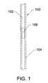
- FIG. 1is a schematic representation of a blood vessel in a mammalian body, wherein the blood vessel is being occluded, at least partially, by thrombus, clot, plaque, or other obstruction;
- FIG. 2is a schematic representation of a blood vessel in a mammalian body, wherein a blood vessel occlusion has been traversed by the distal end of a clot removal apparatus, according to an embodiment of the invention
- FIG. 3is a schematic representation of the blood vessel of FIG. 2 , wherein the clot removal apparatus further includes a coaxial catheter, which is advanced proximally to the occlusion, according to an embodiment of the invention;
- FIG. 4is a schematic representation of the blood vessel and apparatus in FIG. 3 , wherein a distal segment of the clot removal apparatus has been re-configured into a coil, according to an embodiment of the invention
- FIG. 5is a schematic representation of the blood vessel and apparatus in FIG. 4 , wherein the coiled distal segment of the clot removal apparatus has been withdrawn proximally through the occlusion so as to core or remove a portion or all of the occlusion, according to an embodiment of the invention;
- FIG. 6is a schematic representation of the blood vessel and apparatus in FIG. 5 , wherein the distal end of the coaxial catheter has been expanded to envelop all, or a portion, of the occlusion removed by the coiled distal segment, according to an embodiment of the invention
- FIG. 7is a schematic representation of the blood vessel and apparatus in FIG. 6 , wherein a region of the clot removal apparatus, disposed proximal to the occlusion, has been reconfigured into a coil so that the occlusion is sandwiched between the proximal and distal coils, according to an embodiment of the invention;
- FIG. 8is an illustration of a cross-section of the clot removal apparatus showing the shape memory element, a heating element, an insulation element, and an electrical conductor element, according to an embodiment of the invention
- FIG. 9is an oblique illustration of an expandable distal tip of a coaxial receiving catheter, according to an embodiment of the invention.
- FIG. 10illustrates the proximal end of a clot removal apparatus 1000 , according to an embodiment of the invention
- FIG. 11illustrates a composite clot removal wire construction, according to an embodiment of the invention
- FIG. 12 aillustrates a double coil clot removal system wherein the distal coil can be withdrawn proximally toward the proximal coil, according to an embodiment of the invention.
- FIG. 12 billustrates the double coil clot removal system of FIG. 12 a wherein the two coils have been brought closer together to clamp the clot prior to removal, according to an embodiment of the invention.
- the present inventionis directed to methods and devices for removing obstructions from blood vessels.
- the devicemay be used to retrieve and remove clots and other biological obstructions.
- the devicemay also be used to retrieve embolic coils and the like which have been misplaced or have migrated to an undesirable location.
- a catheteris advanced to the region of an obstruction.
- the obstructioncan reside within a body vessel or lumen.
- the body vessel or lumencan be that of a human, mammal, or other animal.
- the body vesselcan be a blood vessel, a lymphatic duct, a bile duct, a ureter, or any other body vessel.
- a blood vesselcan be either a vein or an artery.
- the obstructioncan be partial or total.
- the obstructioncan have a central orifice or a through orifice that is disposed closer to one side of the vessel than another side (off-center).
- the cathetercan be advanced transluminally, transvascularly, endovascularly, or the like from the access site to the target site.
- the cathetercan be advanced under fluoroscopic guidance with the aid or radiopaque markers affixed to the catheter. At least some of the radiopaque (RO) markers can be affixed at or near the distal end of the catheter.
- ROradiopaque
- the catheter or thrombectomy devicecan comprise a guiding catheter, or microcatheter, and a central wire.
- the central wirecan comprise shape memory alloys such as nitinol.
- the central wirecan comprise radiopaque markers fabricated from materials such as, but not limited to, tantalum, platinum, iridium, gold, and the like.
- the central wirecan also comprise Ohmic, or resistive, heating elements such as nickel-chromium wire exhibiting high resistance and advantageous heat generation given an electrical current applied across the Ohmic-heating element.
- the central wirecan comprise thermal insulation.
- the central wirecan comprise one or more electrical conductors, leads, bus lines, or the like.
- the central wirecan be configured to pierce or advance through a clot or other obstruction with a conical, sharpened, or small diameter distal tip.
- the central wirecan comprise one or more radiopaque markers.
- the central wirecan be configured to be straight with a certain amount of flexibility and column strength during advancement to a target site and across an obstruction.
- the distal end of the central wirecan form a coil, a complex coil, a conical coil, a rat's nest, a ball, or other structure.
- the diameter of the structure formed above transition temperaturecan be greater than, equal to, or less than the diameter of the parent vessel or lumen.
- Heating and restructuring of the distal end of the central wirecan be accomplished by application of electrical, thermal, electromagnetic, sound, or other energy to the distal end of the catheter.
- the energycan be applied to the proximal end of the catheter and then be transmitted over appropriate energy conduits, for example electrical leads or an electrical bus, to the distal end of the catheter.
- the coil structure at the distal end of the wireadvantageously comprises sufficient internal strength that, when it is pulled through a thrombus structure, it can retain its shape and deform, excise, cut, core, or otherwise remove the thrombus structure from the vessel, in whole or in part.
- the coaxial catheter, microcatheter, guide catheter, or receiving cathetercan comprise a distal end that is radially expandable.
- the receiving catheter distal endcan comprise rails, ribs, stays, battens, reinforcements, or bands of metal that are biased outwardly and are selectively restrained inwardly with an outer, coaxial, retractable sheath.
- the receiving catheter distal endcan comprise ribs or bands of metal that can be biased outwardly using shape memory properties upon energy delivery from the proximal end of the catheter or directly into the target site.
- Exemplary materials for use in the receiving catheter distal endinclude nitinol, stainless steel, titanium, cobalt nickel alloys, or the like.
- Energy delivery from the proximal endfor the purpose of forming coils in the wire or expanding the receiving catheter distal end, includes electrical energy, either AC or DC in voltages ranging from 1.2 Volts to 240 Volts.
- Energy delivery, for both coil configuration and catheter expansion, at the distal endincludes microwave, high intensity focused ultrasound (HIFU), radiofrequency (RF), or other types of energy.
- the receiving catheter distal endcan be fabricated with a malleable reinforcement embedded within a polymeric surround, wherein the malleable reinforcement is sufficiently strong so as to substantially control the configuration of the polymeric surround.
- the polymeric surroundis fabricated from polyethylene with a total thickness of 0.008 to 0.020 inches and an annealed stainless steel coil with thickness of 0.002 to 0.005 inches and a width of 0.020 to 0.125 inches is embedded therein.
- the spacing between the coil turnscan range from 0.010 to 0.250 inches.
- the malleable thin wall distal endcan be folded along longitudinal creases to reduce its diameter.
- a high-pressure angioplasty-type balloon disposed inside the lumen of the distal endcan be inflated to radially expand the catheter.
- the angioplasty-type balloonreferred to as a dilation balloon, can be disposed on the central wire or a separate catheter placed alongside the wire.
- the inventionwhich is generally termed a catheter, sheath, or wire, can be described as being an axially elongate hollow tubular structure having a proximal end and a distal end.
- the axially elongate structurefurther has a longitudinal axis and has an internal through lumen that extends from the proximal end to the distal end for the passage of instruments, fluids, tissue, or other materials.
- the axially elongate hollow tubular structureis generally flexible and capable of bending, to a greater or lesser degree, through one or more arcs in one or more directions perpendicular to the main longitudinal axis.
- the proximal end of the deviceis that end that is closest to the user, typically a cardiologist, surgeon, radiologist, interventional neuroradiologist, or electrophysiologist.
- the distal end of the deviceis that end closest to the patient or that is first inserted into the patient.
- a direction being described as being proximal to a certain landmarkwill be closer to the user, along the longitudinal axis, and further from the patient than the specified landmark.
- the diameter of a catheteris often measured in “French Size” which can be defined as 3 times the diameter in millimeters (mm). For example, a 15 French catheter is 5 mm in diameter.
- the French sizeis designed to approximate the circumference of the catheter in mm and is often useful for catheters that have non-circular cross-sectional configurations. While the original measurement of “French” used ⁇ (3.14159 . . . ) as the conversion factor between diameters in millimeters (mm) and French, the system has evolved today to where the conversion factor is 3.0.
- FIG. 1is a schematic representation of a blood vessel 100 in a mammalian body, wherein the blood vessel 100 is being occluded, at least partially, by thrombus, clot, plaque, or other obstruction 106 .
- the blood vessel 100further comprises a vessel lumen 102 and a wall 104 .
- the blood vessel 100can be a vein or an artery.
- the blood vesselcan be as large in diameter as the aorta, which can range from 1.5 cm to 3.5 cm diameter.
- the vesselcan be as small in diameter as a coronary artery (2 to 4 mm diameter) or a vessel in the neurovasculature (1 to 4 mm diameter).
- the vessel lumen 102generally comprises blood (not shown), which should be flowing therethrough.
- the presence of the obstruction 106can compromise blood flow and result in tissues downstream not receiving adequate oxygenation or nutrition for continued health.
- the compromised blood flowcan lead to tissue ischemia and ultimately cell death if the compromised blood flow remains untreated for an extended period of time
- FIG. 2is a schematic representation of a blood vessel 100 in a mammalian body, wherein a blood vessel occlusion 106 has been traversed by a distal end of a substantially straight clot removal apparatus 200 .
- the blood vessel occlusion 106resides within the vessel lumen 102 of the blood vessel 100 and extends all the way to the walls 104 of the blood vessel.
- the clot removal apparatus wire 200is generally straight and its longitudinal axis generally follows the longitudinal axis of the blood vessel 100 .
- the clot removal apparatus 200is configured straight during the insertion phase.
- the clot removal apparatus 200is advantageously flexible but retains significant column strength so it can be advanced through thrombus material.
- the clot removal apparatus 200can be a single structure fabricated from shape memory nitinol or it can be a composite structure.
- the clot removal apparatus 200can comprise an external coil surround (refer to FIG. 11 ) that covers all or a portion of a central core portion of the clot removal apparatus 200 .
- the clot removal apparatus 200can have a length ranging from about 10-cm to 250-cm, preferably between around 25 and 175-cm, and more preferably between about 50 and 150-cm.
- the diameter of the clot removal apparatus 200 in the region where it pierces the obstruction 106can range between about 0.002 inches and 0.040 inches, and preferably between about 0.005 and 0.030 inches, with a target range of between about 0.007 and 0.013 inches.
- the shape memory transition temperaturecan range between about 25 degrees centigrade to around 32 degrees centigrade if body heat transition is used to configure the coil.
- the A fcan also range from around 37 degrees centigrade to as high as about 45 degrees centigrade if Ohmic heating is used.
- the austenite finish temperaturecan range from about 39 to 44 degrees centigrade while the austenite start temperature (A S ) can range from about 35 to 42 degrees centigrade.
- Hysteresis effectscan be used to maintain the deformed non-straight coil shape even when heating energy is removed since the martensite start (M s ) temperature is generally below the austenite finish (A f ) temperature.
- the clot removal apparatus 200can be fabricated from equiatomic or nickel-rich nitinol.
- the nitinolis a nickel titanium alloy, which contains approximately 50% to 55.6% nickel.
- the nitinolcan be heat treated to set the transition temperature at about 28 to 32 degrees centigrade.
- Shape setting of the clot removal apparatus 200 into its activated configurationinvolves heating the clot removal apparatus 200 when constrained about a mandrel or fixture that forces the clot removal apparatus 200 into its substantially non-straight final shape, such as a coil, etc. The heating can be performed at temperatures ranging from about 480 degrees centigrade to 550 degrees centigrade with a preferred temperature range of about 500 to 525 degrees centigrade.
- the heating timecan range from about 3 minutes to about 15 minutes or longer, although increased heating time tends to increase the austenite finish transition temperature (Af).
- the clot removal clot removal apparatus 200 and its mandrelare removed from the heating system and quenched in water or other liquid at about room temperature, for example about 22 ⁇ 20 degrees centigrade.
- the heating systemcan be an oven, a convection oven, a sand bath, a salt bath, or the like.
- FIG. 3is a schematic representation of the blood vessel 100 of FIG. 2 , wherein the clot removal apparatus 200 further includes a coaxial catheter 300 , further comprising a central lumen 302 , which is advanced proximally to the occlusion 106 .
- the catheter 300is slidably disposed over the clot removal apparatus 200 within the central lumen 302 of the catheter 300 .
- the catheter 300can be a guiding catheter, a microcatheter such as is used in the neurovasculature and having continuously or discreet regions of progressively greater flexibility moving from the proximal to the distal end, or the like.
- the catheter 300can be configured to fit within the vessel lumen 102 and may have increasing stiffness moving from proximal to distal to permit guidance and pushability.
- the catheter 300can have a length ranging from about 50 cm to about 150 cm.
- the wall thickness of the catheter 300can range from about 0.003 to 0.020 inches, and the wall thickness can vary along the length of the catheter 300 .
- the inner lumen 302 of the catheter 300can have a diameter ranging from about 0.005 to 0.025 inches with a preferred range of about 0.008 to 0.020 inches.
- the catheter 300can further comprise radiopaque markers 304 , for example rings or bands of polymer or metal, comprising materials such as, but not limited to, platinum, platinum iridium, tantalum, gold, barium sulfate, or the like, affixed at or near the distal end of the catheter 300 to assist in manipulation and location under fluoroscopy.
- the radiopaque (RO) markers 304can have lengths ranging from about 0.010 inches to 0.100 inches with wall thicknesses ranging from about 0.002 to 0.015 inches.
- the clot removal apparatus 200can be extended out the distal end of the catheter 300 or it can be withdrawn partially or completely inside the catheter 300 .
- the catheter 300can be fabricated from polymeric materials such as, but not limited to, Pebax, polyethylene, polyurethane, PEEK, polypropylene, Hytrel, polyimide, polyamide, or the like.
- the catheter 300can further be built up with inner and outer layers of polymer and a central reinforcing layer of coil or braid, fabricated from materials such as, but not limited to, stainless steel, PEN, polyethylene terephthalate (PET), or the like.
- the proximal end of the catheter 300can be terminated with a hub or other structure comprising a Luer fitting, bayonet-mount, hemostasis valve, stopcock, or the like.
- FIG. 4is a schematic representation of the blood vessel 100 and clot removal apparatus 200 , wherein a distal segment of the clot removal apparatus 200 has been re-configured into a coil 400 .
- the clot removal apparatus 200having its distal end positioned distal to the obstruction 106 , relative to the operator, has now been activated by heating or other means to cause the clot removal apparatus 200 to reconfigure into the coil 400 .
- the coil 400can have from about 1 to 40 turns and can be cylindrical, conical, ball shaped, irregularly shaped, or possess any shape suitable for effectively expanding its diameter and ability to withdraw the clot 106 proximally.
- the coil and coil region 400can be integral, or separately attached, to the clot removal apparatus 200 .
- the coil 400is formed when the shape memory material, for example nitinol, is heated either by the blood or by energy imparted thereon. Electrical energy can be imparted to the coil 400 through the clot removal apparatus 200 by means of electrical conductors, preferably insulated or isolated electrically. At least one and optionally two or more conductors can be disposed along the length of the clot removal apparatus 200 so that electrical power can be applied at the proximal end of the clot removal apparatus 200 and transmitted along the length of the clot removal apparatus 200 to be delivered to the coil 400 or adjacent heating element.
- the diameter of the coil 400should approximate that of the vessel lumen 102 but can also be smaller.
- Typical coil 400 diameterscan range between about 2 mm and 10 mm with a preferred range of about 3 mm to 5 mm in the cerebrovascular setting, for example.
- the number of turns of the coil 400can range from about 1 to 15 with a preferred range of about 2 to 8.
- FIG. 5is a schematic representation of the blood vessel 100 and clot removal apparatus 200 in FIG. 4 , wherein the coiled distal segment 400 of the clot removal apparatus 200 has been withdrawn proximally through the occlusion 106 so as to remove a core portion 500 or all of the occlusion 106 .
- the coil 400is illustrated residing proximally to the location of the occlusion 106 along with the retrieved piece of occlusion, clot, or thrombus 500 .
- the distal end 502 of the receiving catheter 300is illustrated in its radially collapsed configuration.
- the expandable distal region 502 of the receiving catheter 300can be integral to, or separately affixed to, the distal end of the receiving catheter 300 .
- the occlusion 106following proximal withdrawal of the coil 400 , comprises a central opening, core, or lumen 504 , through which blood can now flow without the effect of stenosis.
- Electrocautery methodologydelivering coagulation or cutting current to the coil 400 from the proximal end of the system, can be used to modify the clot removal capabilities of the device.
- FIG. 6is a schematic representation of the blood vessel 100 and clot removal apparatus 200 , wherein the distal end 502 of the coaxial catheter 300 has been expanded to envelop all, or a portion, of the occlusion 500 removed by the coiled distal segment 400 .
- the central opening or lumen 504 of the obstruction 160provides reduced resistance to blood flow through the vessel 100 .
- the clot removal apparatus 200has been withdrawn proximally so that all but a small portion of the retrieved occlusion 500 and the coil 400 have been enveloped and retrieved within the catheter 300 .
- the expandable region 502 at the distal end of the retrieval catheter 300can have been expanded due to shape-memory forces acting in response to applied heat or energy, due to withdrawal of an external sheath to allow an elastomeric structure to expand outward, due to passive “shoehorning” of the coil 400 and retrieved clot 500 into the expandable region 502 , or due to radially outward dilation forces generated by an internal dilator (not shown), either removable or non-removable.
- the internal dilatorcan be a balloon catheter coaxially mounted around, or co-inserted in a parallel fashion alongside, the clot retrieval clot removal apparatus 200 .
- the dilatation meansmay rely on axial compression of a braid to expand its diameter, or it may be a translation dilator wherein an inner tube is advanced longitudinally to expand an elastomeric small diameter tube, as described in U.S. Pat. No. 7,309,334, issued on Dec. 18, 2007, the entirety of which is hereby incorporated herein by reference. Dilation may also occur as a result of unfurling a thin-film wrapped tube or by rotation of a series of hoops so that their alignment is at right angles to the long axis of the catheter.
- the shoehorn effectcan be generated because the coil 400 is affixed to the clot removal apparatus 200 at a single point and is able to elongate and constrict inward somewhat under proximal axially directed loading. This constriction can force the excised clot or occlusion 500 to also contract radially to fit within the expandable part 502 of the catheter 300 .
- FIG. 7is a schematic representation of the blood vessel 100 and apparatus 200 , wherein a region of the clot removal apparatus 200 , disposed proximal to the occlusion 106 , has been reconfigured into a coil 700 so that the occlusion 106 is sandwiched between the proximal 700 and distal 400 coils.
- the proximal coil 700can be configured to expand separately or at the same time as the distal coil 400 . Different coil 400 and 700 expansion times can be generated by separate electrical connections to the proximal end of the clot removal apparatus 200 wherein only one is activated at a time. In other embodiments, the austenite finish temperature of the two coils 400 and 700 can be different to allow one to expand before the other.
- proximal coil 700 and distal coil 400it may be possible to eliminate the catheter 300 or to use a larger catheter disposed far proximally to the target occlusion 106 in a correspondingly larger vessel.
- the proximal coil 700can prolapse at its outermost aspect to encompass and surround the excised region of occlusion 500 .
- the distal coil 400can expand within the occlusion 106 and thereby grab and embed itself within the occlusion 106 to facilitate removal of the mass 500 .
- FIG. 8is an illustration of a cross-section of another embodiment of a clot removal apparatus 200 a comprising a shape memory element 802 , a heating element 804 , an insulation element 808 , a fluid channel or lumen 810 , and one or more electrical conductor element 806 .
- This embodiment of the clot removal apparatus 200 aand may further comprise radiopaque markers 812 fabricated from materials such as, but not limited to, tantalum, platinum, iridium, gold, and the like. These radiopaque markers 812 can have a thickness ranging from 0.0005 to 0.020 inches.
- the radiopaque markers 812can be circumferential bands, or discreet masses of radio-dense materials that are readily visible under fluoroscopy and which are embedded in the structures 802 or 808 comprising the wall of the catheter 200 .
- the heating element 804can comprise high resistance materials such as ceramics and metals such as, but not limited to, nickel chromium wire, tungsten wire, and the like.
- the insulation element 808is electrically insulating.
- the insulation element 808can be thermally insulating to minimize heating effects on surrounding tissue.
- the Shape memory element 802is illustrated as a cylinder or tubular structure and encloses the heating element 804 to further dissipate heating effects of the heating element.
- the electrical conductor element 806delivers energy to the distal end of the heating element 804 .
- the heating element 804is surrounded by electrical insulation and is doubled up so that both electrical connections are made at the proximal end of the clot removal wire 200 .
- a plurality of electrical conductors 806can be used to activate multiple coils, for example the proximal coil 700 and the distal coil 400 .
- a separate electrical insulatorsurrounds the entirety, a portion of, or the exterior of electrical conductor 806 .
- the shape memory element 802can be configured as a solid wire or it can be a tubular structure.
- a tubular structurecan be configured to impart more force than a solid wire structure given the same cross-sectional area.
- the shape memory element 802can be a secondary coil 1104 or 1106 .
- the secondary coil 1104 , 1106can be wound around the core wire, heating element 804 .
- the fluid lumen 810can be used to even the heating pattern of the heating elements 804 , of which two are shown in FIG. 8 , or it can be used for purging, aspiration, infusion, or withdrawal of fluids to or from the patient.
- the fluid lumen 810can be operably connected to a fluid infusion port ( FIG. 10 ) at the proximal end of the clot removal wire 200 .
- the outer diameter of the clot removal wire 200can range from 0.004 inches to 0.050 inches and preferably range from 0.006 inches to 0.040 inches in diameter.
- FIG. 9is an oblique illustration of an expandable distal region 502 of a coaxial receiving catheter 300 .
- the expandable region 502comprises longitudinal stringers, battens, fingers, plates, wires, or the like 904 .
- the longitudinal stringers 904are configured to maintain column strength to prevent axial collapse of the expandable distal region 502 when a clot removal coil 400 is withdrawn therein.
- the region between the longitudinal stringers 904comprises elastomeric, furled, longitudinally folded, or non-elastomeric, polymers capable of expanding in circumference. Such expansion can be uniform along the length of the expandable region 502 , as shown in FIG. 6 or it can be funnel shaped as shown in FIG. 9 .
- the expandable region 502can also be configured as a cylindrical shutter structure or iris that expands when the proximal end is rotated relative to the distal end.
- the stringers 904can be fabricated from polymers such as, but not limited to, polyester, polyimide, polyamide, PEEK, Hytrel, or the like.
- the stringers 904can also comprise metals such as, but not limited to, nitinol, stainless steel, tantalum, platinum, titanium, or the like.
- the thickness of the stringers 904can range from about 0.010 inches to about 0 inches smaller than the wall thickness 902 of the catheter 502 .
- FIG. 10illustrates the proximal end of a clot removal apparatus 1000 comprising a clot removal wire 200 , a receiving catheter 300 , a catheter hub 1002 , a wire hub 1014 , a wire electrical connection 1024 , a catheter electrical bus 806 , a wire electrical bus 1016 , a catheter expansion switch 1008 , a clot retrieval activation switch 1010 , a secondary coil expansion switch 1022 , a catheter electrical connection 1004 , and a hemostasis valve 1012 .
- the catheter hub 1002further comprises a sideport 1018 with a valve 1020 .
- the wire hub 1014can further comprise an inlet port with valve 1026 .
- the hemostasis valve 1012comprises a variable diameter central lumen (not shown) capable of accepting and sealing against guidewires, the clot retrieval wire 200 , or sealing without anything inserted therethrough.
- the catheter hub 1002is affixed to the proximal end of the catheter tubing 300 .
- the wire hub 1014is affixed to the proximal end of the clot removal wire 200 .
- the Hemostasis valve 1012affixed or integral to the catheter hub 1002 can be a Tuohy-Borst valve, slit valve, duckbill valve, a ball valve, a gate valve, a membrane with a closeable hole therein, or a combination of these.
- the wire electrical input connector 1024can comprise one or a plurality of electrical bus leads 1016 , which would be advantageously electrically insulated from each other.
- the wire hub 1014can further comprise electrical switches, for example a switch 1008 to enable the distal coil formation and a switch 1022 to enable proximal coil formation.
- the wire hub 1014can comprise temperature readouts, for example gauges or digital displays, operably connected to thermocouples or thermistors affixed at or near the distal end of the wire in important temperature measurement regions. Referring to FIG. 7 , the distal coil enable switch 1008 and the proximal coil enable switch 1022 are operably connected to the electrical bus 1016 , from which the switches draw power, when closed to activate their respective coils 400 and 700 at the distal end of the wire 200 .
- the wire electrical connector 1024in an embodiment, can be operably connected to an external power source, for example about 1.5 VDC to 24 Volts DC, or alternating power sources with output levels up to 220 VAC. In another embodiment, the wire electrical connector 1024 can be operably connected to batteries housed externally or internally to the wire hub 1014 .
- the catheter hub 1002can have its electrical connector 1004 similarly connected to an external electrical power supply or to an internal battery power supply.
- the catheter hub 1002can have a sideport 1018 with a valve 1020 affixed thereto.
- the sideport 1018 and valve 1020can be used for advancement of secondary catheters, or for the infusion and withdrawal of fluids from a lumen 906 within the catheter 300 .
- the catheter hub 1002 and the wire hub 1014can be fabricated from polymers including, but not limited to, polyurethane, polyethylene, polycarbonate, PEBAX, PEEK, Hytrel, polysulfone, or the like.
- the wire hub 1014can have affixed, thereto, the fluid infusion or withdrawal port 1026 which can further be terminated with a valve.
- the fluid infusion or withdrawal port 1026can be directly affixed to the wire hub 1014 or it can further comprise a length of tubing (not shown) having a central lumen in communication with the port 1026 and a lumen within the wire (not shown).
- the fluid infusion or withdrawal port 1026can further be operably connected to a dilation balloon suitable for expanding the distal end 502 of the catheter 300 .
- FIG. 11illustrates an alternative embodiment of a clot removal wire 1100 .
- the clot removal wire 1100comprises a core wire 1102 , and a first surrounding coil 1104 and a second surrounding coil 1106 .
- the surrounding coil 1104can extend the entire length of the core wire 1102 or it can be separated from coil 1106 by a gap 1108 .
- the clot removal wire 1100can comprise one coil 1104 , two coils 1104 and 1106 as illustrated, or it can comprise a plurality of coils (n ⁇ 2) separated by a plurality of gaps 1108 . This segmented construction is advantageous in that it possesses column strength, bendability, shape control, and kink resistance.
- the core wire 1102can comprise a shape memory element or materials or the coil 1104 can comprise shape memory materials, coil 1106 can comprise shape memory materials, or all coils can comprise shape memory materials.
- the transition temperatures of each coilcan be substantially the same or they can be different to allow the clot removal wire 1100 to assume various shapes.
- the shape memory element temperaturesrise above a given transition temperature and move to reconfigure toward pre-set shapes.
- the coils 1104 and 1106when the energy source is removed from the shape memory wire 1100 , the coils 1104 and 1106 , for example, cool below their martensite finish (M f ) temperature and become softer, thus allowing the core wire 1102 , which can be elastomeric, to overpower the coils 1104 and 1106 and return the clot removal wire 1100 to its original approximately straight shape.
- M fmartensite finish
- the target siteis initially diagnosed using fluoroscopy, angiography, magnetic resonance imaging, ultrasound, and the like.
- the target siteis a region of occlusion within the cerebrovasculature.
- a Seldinger techniqueis applied to gain guidewire access to a vessel, for example the right or left femoral artery.
- the guidewireis routed to the site of the target lesion 106 within the target vessel 100 , often more than 100 cm distant from the access site.
- the catheter 300is advanced over the guidewire and the guidewire is removed.
- the clot removal wire 200is advanced through the catheter 300 until it reaches the target site in the vessel 100 .
- the clot removal wire 200is advanced across the lesion 106 .
- the clot removal wire 200is reconfigured into a coil 400 at its distal end by applying electrical power at the proximal end or by the application of radio frequency (RF), HIFU, microwave, or other energy at the distal end within the body.
- RFradio frequency
- the distal coil 400is withdrawn with the clot removal wire 200 proximally toward the catheter 300 .
- the distal coil 400excises from the vessel wall and removes some, or all, of the lesion 106 .
- the entire clot 500 excised from the lesion 106can be pulled out of the patient along with the catheter 300 or it can be first withdrawn within the distal end 502 of the catheter 300 .
- the distal end 502is preferably radially expandable and such expansion can be actively performed at the proximal end of the sheath or catheter 300 by application of electrical energy, or using the same techniques discussed previously about activating the distal end using HIFU, microwaves, RF energy, or the like.
- Other regions of occlusion suitable for treatment using the means described hereininclude blockages of the coronary arteries, the pulmonary vasculature, or the like.
- the distal coil 400shown in FIG. 4 , can be expanded by heating the shape memory material comprising the coil above its austenite finish temperature.
- the distal coil 400can be contracted or straightened out by cooling the shape memory material.
- the distal coil 400is allowed to cool and re-shape itself into a straight configuration once the excised clot 500 is safely retrieved within the distal region 502 of the catheter 300 .
- the distal coil 400 , the proximal coil 700 , or bothcan comprise superelastic materials and be enshrouded within a sleeve to maintain a straight shape. When the sleeve is withdrawn proximally relative to the coil wire, the superelastic coils can form.
- the coils 400 and 700can be used to clean obstructions within the vessel in the same way as coils 400 and 700 , which are shape-memory in nature.
- FIG. 12 aillustrates a dual coil clot retrieval system 1200 comprising a catheter 300 , a proximal coil 1206 , a distal coil 1202 , a port 1204 in a hollow delivery wire 1208 for the proximal coil 1206 , and a distal coil delivery wire 1210 .
- the system 1200is resident in the blood vessel 104 comprising the lumen 102 .
- the distal coilis illustrated having passed distally to the occlusion 106 but the spacing between the two coils 1202 and 1206 exceeds the length of the obstruction 106 .
- the distal coil delivery wire 1210is radially constrained by and longitudinally movable within the lumen of the hollow proximal coil delivery wire 1208 by control exerted on a hub affixed to the proximal end of the hollow delivery wire 1208 .
- FIG. 12 billustrates the dual coil clot retrieval system 1200 wherein the distal coil 1202 has been withdrawn proximally toward the proximal coil 1206 to trap the thrombus or occlusion 106 at both ends.
- the entire system 1200 with trapped clot 106can be withdrawn proximally into a receiving catheter located within the vessel lumen 102 surrounded by the vessel wall 104 .
- the method of using the obstruction removal systemcan comprise the steps of inserting an axially elongate obstruction removal wire into a body vessel or lumen, wherein the obstruction removal wire comprises a proximal end, a distal end, and a longitudinal axis, routing the obstruction removal wire to the region of a target obstruction within a body vessel or lumen in a generally straight configuration, advancing the obstruction removal wire through the target obstruction so that a pre-defined expansible region of the obstruction removal wire, proximate the distal end of the obstruction removal wire, extends beyond the obstruction, applying energy to the obstruction removal wire, transmitting the energy to the pre-defined expansible region, deforming the pre-defined expansible region into a substantially non-straight configuration, and withdrawing the expansible region proximally to remove at least a portion of the target obstruction.
- the methodcan further comprise the step of removing the obstruction removal system from the patient.
- the methodcan further comprise the step first routing an axially elongate guide catheter to the site of the lesion, removing any guidewires, and then inserting the obstruction removal system, clot removal system, clot removal system, or the like, through the guide catheter.
- the methodcan further comprise the step of expanding the distal end of the guide catheter.
- the methodcan further comprise the step of removing the guide catheter from the body vessel or lumen of the patient.
- the present inventionmay be embodied in other specific forms without departing from its spirit or essential characteristics.
- the clot removal systemcan expand within the obstructive clot, or it can expand distal to the obstructive clot and be withdrawn against the clot.
- a cathetercan be used to envelop and retrieve the removed obstruction; it can be used to guide the clot removal apparatus into place; or both.
- the embodiments described hereinfurther are suitable for fabricating very small diameter catheters, microcatheters, or sheaths suitable for cardiovascular or neurovascular access.
- Various valve configurations and radiopaque marker configurationsare appropriate for use in this device.
- the distal coil and the proximal coilcan be used, alone or in combination, to ensnare and remove an implant such as a stent, embolic coil, or the like.
- an implantsuch as a stent, embolic coil, or the like.
- the described embodimentsare to be considered in all respects only as illustrative and not restrictive. It is to be further appreciated that the invention has been described hereabove with reference to certain examples or embodiments of the invention but that various additions, deletions, alterations and modifications may be made to those examples and embodiments without departing from the intended spirit and scope of the invention. For example, any element or attribute of one embodiment or example may be incorporated into or used with another embodiment or example, unless to do so would render the embodiment or example unsuitable for its intended use.
Landscapes
- Health & Medical Sciences (AREA)
- Surgery (AREA)
- Life Sciences & Earth Sciences (AREA)
- Heart & Thoracic Surgery (AREA)
- Nuclear Medicine, Radiotherapy & Molecular Imaging (AREA)
- Vascular Medicine (AREA)
- Engineering & Computer Science (AREA)
- Biomedical Technology (AREA)
- Orthopedic Medicine & Surgery (AREA)
- Medical Informatics (AREA)
- Molecular Biology (AREA)
- Animal Behavior & Ethology (AREA)
- General Health & Medical Sciences (AREA)
- Public Health (AREA)
- Veterinary Medicine (AREA)
- Surgical Instruments (AREA)
Abstract
Description
Claims (6)
Priority Applications (1)
| Application Number | Priority Date | Filing Date | Title |
|---|---|---|---|
| US12/187,227US8343167B2 (en) | 2007-08-06 | 2008-08-06 | Thrombectomy system and method |
Applications Claiming Priority (2)
| Application Number | Priority Date | Filing Date | Title |
|---|---|---|---|
| US96363707P | 2007-08-06 | 2007-08-06 | |
| US12/187,227US8343167B2 (en) | 2007-08-06 | 2008-08-06 | Thrombectomy system and method |
Publications (2)
| Publication Number | Publication Date |
|---|---|
| US20090054918A1 US20090054918A1 (en) | 2009-02-26 |
| US8343167B2true US8343167B2 (en) | 2013-01-01 |
Family
ID=40342026
Family Applications (1)
| Application Number | Title | Priority Date | Filing Date |
|---|---|---|---|
| US12/187,227Active2029-09-16US8343167B2 (en) | 2007-08-06 | 2008-08-06 | Thrombectomy system and method |
Country Status (3)
| Country | Link |
|---|---|
| US (1) | US8343167B2 (en) |
| EP (1) | EP2180839A4 (en) |
| WO (1) | WO2009021071A2 (en) |
Cited By (66)
| Publication number | Priority date | Publication date | Assignee | Title |
|---|---|---|---|---|
| US20080154293A1 (en)* | 2006-12-22 | 2008-06-26 | The Spectranetics Corporation | Retractable Separating Systems and Methods |
| US20080154296A1 (en)* | 2006-12-22 | 2008-06-26 | The Spectranetics Corporation | Tissue Separating Systems and Methods |
| US20120158034A1 (en)* | 2010-12-16 | 2012-06-21 | Wilson Thomas S | Expandable Implant and Implant System |
| US8974512B2 (en) | 2010-09-10 | 2015-03-10 | Medina Medical, Inc. | Devices and methods for the treatment of vascular defects |
| US20150075862A1 (en)* | 2013-09-19 | 2015-03-19 | Hitachi Metals, Ltd. | Harness |
| US8984733B2 (en) | 2013-02-05 | 2015-03-24 | Artventive Medical Group, Inc. | Bodily lumen occlusion |
| US8998947B2 (en) | 2010-09-10 | 2015-04-07 | Medina Medical, Inc. | Devices and methods for the treatment of vascular defects |
| US9017351B2 (en) | 2010-06-29 | 2015-04-28 | Artventive Medical Group, Inc. | Reducing flow through a tubular structure |
| US9095344B2 (en) | 2013-02-05 | 2015-08-04 | Artventive Medical Group, Inc. | Methods and apparatuses for blood vessel occlusion |
| US9149277B2 (en) | 2010-10-18 | 2015-10-06 | Artventive Medical Group, Inc. | Expandable device delivery |
| US9247942B2 (en) | 2010-06-29 | 2016-02-02 | Artventive Medical Group, Inc. | Reversible tubal contraceptive device |
| US9283040B2 (en) | 2013-03-13 | 2016-03-15 | The Spectranetics Corporation | Device and method of ablative cutting with helical tip |
| US9291663B2 (en) | 2013-03-13 | 2016-03-22 | The Spectranetics Corporation | Alarm for lead insulation abnormality |
| US9375333B1 (en) | 2015-03-06 | 2016-06-28 | Covidien Lp | Implantable device detachment systems and associated devices and methods |
| US9413896B2 (en) | 2012-09-14 | 2016-08-09 | The Spectranetics Corporation | Tissue slitting methods and systems |
| USD765243S1 (en) | 2015-02-20 | 2016-08-30 | The Spectranetics Corporation | Medical device handle |
| US9456872B2 (en) | 2013-03-13 | 2016-10-04 | The Spectranetics Corporation | Laser ablation catheter |
| USD770616S1 (en) | 2015-02-20 | 2016-11-01 | The Spectranetics Corporation | Medical device handle |
| US9603618B2 (en) | 2013-03-15 | 2017-03-28 | The Spectranetics Corporation | Medical device for removing an implanted object |
| US9636116B2 (en) | 2013-06-14 | 2017-05-02 | Artventive Medical Group, Inc. | Implantable luminal devices |
| US9668765B2 (en) | 2013-03-15 | 2017-06-06 | The Spectranetics Corporation | Retractable blade for lead removal device |
| US9681876B2 (en) | 2013-07-31 | 2017-06-20 | EMBA Medical Limited | Methods and devices for endovascular embolization |
| US9737308B2 (en) | 2013-06-14 | 2017-08-22 | Artventive Medical Group, Inc. | Catheter-assisted tumor treatment |
| US9737306B2 (en) | 2013-06-14 | 2017-08-22 | Artventive Medical Group, Inc. | Implantable luminal devices |
| US9883885B2 (en) | 2013-03-13 | 2018-02-06 | The Spectranetics Corporation | System and method of ablative cutting and pulsed vacuum aspiration |
| US9925366B2 (en) | 2013-03-15 | 2018-03-27 | The Spectranetics Corporation | Surgical instrument for removing an implanted object |
| US9980743B2 (en) | 2013-03-15 | 2018-05-29 | The Spectranetics Corporation | Medical device for removing an implanted object using laser cut hypotubes |
| US10010328B2 (en) | 2013-07-31 | 2018-07-03 | NeuVT Limited | Endovascular occlusion device with hemodynamically enhanced sealing and anchoring |
| US10136913B2 (en) | 2013-03-15 | 2018-11-27 | The Spectranetics Corporation | Multiple configuration surgical cutting device |
| US10149968B2 (en) | 2013-06-14 | 2018-12-11 | Artventive Medical Group, Inc. | Catheter-assisted tumor treatment |
| US10327781B2 (en) | 2012-11-13 | 2019-06-25 | Covidien Lp | Occlusive devices |
| US10363043B2 (en) | 2014-05-01 | 2019-07-30 | Artventive Medical Group, Inc. | Treatment of incompetent vessels |
| US10383691B2 (en) | 2013-03-13 | 2019-08-20 | The Spectranetics Corporation | Last catheter with helical internal lumen |
| US10405924B2 (en) | 2014-05-30 | 2019-09-10 | The Spectranetics Corporation | System and method of ablative cutting and vacuum aspiration through primary orifice and auxiliary side port |
| US10448999B2 (en) | 2013-03-15 | 2019-10-22 | The Spectranetics Corporation | Surgical instrument for removing an implanted object |
| US10478195B2 (en) | 2016-08-04 | 2019-11-19 | Covidien Lp | Devices, systems, and methods for the treatment of vascular defects |
| US10561765B2 (en) | 2015-07-27 | 2020-02-18 | The Texas A&M University System | Medical devices coated with shape memory polymer foams |
| US10675036B2 (en) | 2017-08-22 | 2020-06-09 | Covidien Lp | Devices, systems, and methods for the treatment of vascular defects |
| US10743907B2 (en) | 2014-11-07 | 2020-08-18 | National University Of Ireland, Galway | Thrombectomy device |
| US10779852B2 (en) | 2013-03-15 | 2020-09-22 | National University Of Ireland, Galway | Device suitable for removing matter from inside the lumen and the wall of a body lumen |
| US10813644B2 (en) | 2016-04-01 | 2020-10-27 | Artventive Medical Group, Inc. | Occlusive implant and delivery system |
| US10835279B2 (en) | 2013-03-14 | 2020-11-17 | Spectranetics Llc | Distal end supported tissue slitting apparatus |
| US10842532B2 (en) | 2013-03-15 | 2020-11-24 | Spectranetics Llc | Medical device for removing an implanted object |
| US11129621B2 (en) | 2018-12-17 | 2021-09-28 | Covidien Lp | Devices, systems, and methods for the treatment of vascular defects |
| US11219520B2 (en) | 2017-03-14 | 2022-01-11 | Shape Memory Medical, Inc. | Shape memory polymer foams to seal space around valves |
| US11278342B2 (en) | 2016-04-14 | 2022-03-22 | Theresa Brandner | Medical devices utilizing shape memory alloys and associated systems and methods |
| US11284911B2 (en) | 2016-07-22 | 2022-03-29 | Hesham Morsi | Central clot stabilizer and manipulator |
| US11633818B2 (en) | 2019-11-04 | 2023-04-25 | Covidien Lp | Devices, systems, and methods for treatment of intracranial aneurysms |
| US11707371B2 (en) | 2008-05-13 | 2023-07-25 | Covidien Lp | Braid implant delivery systems |
| US20230240705A1 (en)* | 2012-11-20 | 2023-08-03 | Inari Medical, Inc. | Methods and apparatus for treating embolism |
| US11724069B2 (en) | 2019-04-30 | 2023-08-15 | Covidien Lp | Catheter including contractible electroactive elements |
| US11806033B2 (en) | 2017-01-10 | 2023-11-07 | Inari Medical, Inc. | Devices and methods for treating vascular occlusion |
| US11833023B2 (en) | 2018-08-13 | 2023-12-05 | Inari Medical, Inc. | System for treating embolism and associated devices and methods |
| US11832837B2 (en) | 2004-03-25 | 2023-12-05 | Inari Medical, Inc. | Method for treating vascular occlusion |
| US11844921B2 (en) | 2017-09-06 | 2023-12-19 | Inari Medical, Inc. | Hemostasis valves and methods of use |
| US11844528B2 (en) | 2008-04-21 | 2023-12-19 | Covidien Lp | Multiple layer filamentary devices for treatment of vascular defects |
| US11849963B2 (en) | 2018-01-26 | 2023-12-26 | Inari Medical, Inc. | Single insertion delivery system for treating embolism and associated systems and methods |
| US11864779B2 (en) | 2019-10-16 | 2024-01-09 | Inari Medical, Inc. | Systems, devices, and methods for treating vascular occlusions |
| US11872359B2 (en) | 2020-11-12 | 2024-01-16 | Covidien Lp | Expandable-tip aspiration guide catheter |
| US11918244B2 (en) | 2015-10-23 | 2024-03-05 | Inari Medical, Inc. | Intravascular treatment of vascular occlusion and associated devices, systems, and methods |
| US11931041B2 (en) | 2020-05-12 | 2024-03-19 | Covidien Lp | Devices, systems, and methods for the treatment of vascular defects |
| US11937838B2 (en) | 2013-10-21 | 2024-03-26 | Inari Medical, Inc. | Methods and apparatus for treating embolism |
| US12053203B2 (en) | 2014-03-03 | 2024-08-06 | Spectranetics, Llc | Multiple configuration surgical cutting device |
| US12364496B2 (en) | 2022-01-11 | 2025-07-22 | Inari Medical, Inc. | Devices for removing clot material from intravascularly implanted devices, and associated systems and methods |
| US12364708B2 (en) | 2016-10-21 | 2025-07-22 | Covidien Lp | Injectable scaffold for treatment of intracranial aneurysms and related technology |
| US12433598B2 (en) | 2020-10-13 | 2025-10-07 | Asahi Intecc Co., Ltd. | Thrombus aspiration systems and related methods |
Families Citing this family (67)
| Publication number | Priority date | Publication date | Assignee | Title |
|---|---|---|---|---|
| US10517617B2 (en) | 2007-12-20 | 2019-12-31 | Angiodynamics, Inc. | Systems and methods for removing undesirable material within a circulatory system utilizing a balloon catheter |
| US20170136158A1 (en) | 2015-10-16 | 2017-05-18 | Angiodynamics, Inc. | Systems and Methods for Removing Undesirable Material Within a Circulatory System |
| US11589880B2 (en) | 2007-12-20 | 2023-02-28 | Angiodynamics, Inc. | System and methods for removing undesirable material within a circulatory system utilizing during a surgical procedure |
| EP2309934B1 (en)* | 2008-06-19 | 2018-11-07 | AngioDynamics, Inc. | A thrombectomy catheter and a device comprising the same |
| US9216299B2 (en) | 2009-10-21 | 2015-12-22 | Thomas J. Wolfe | Electromagnetic pathologic lesion treatment system and method |
| EP2490764B1 (en)* | 2009-10-21 | 2014-09-10 | Thomas J. Wolfe | Catheter for electromagnetic thrombus treatment and method of manufacturing |
| US20110130756A1 (en)* | 2009-12-01 | 2011-06-02 | Everson Jr David C | Vasculature device |
| CA2804254C (en) | 2010-02-23 | 2016-11-01 | Medina Medical, Inc. | Devices and methods for vascular recanalization |
| US9192746B2 (en)* | 2010-06-07 | 2015-11-24 | Cook Medical Technologies Llc | Reperfusion catheter system |
| US12245788B2 (en) | 2011-03-15 | 2025-03-11 | Angiodynamics, Inc. | Device and method for removing material from a hollow anatomical structure |
| US9055964B2 (en) | 2011-03-15 | 2015-06-16 | Angio Dynamics, Inc. | Device and method for removing material from a hollow anatomical structure |
| US9345499B2 (en) | 2011-05-26 | 2016-05-24 | Covidien Lp | Pressure activated foreign body removal system and method of use |
| US11026708B2 (en) | 2011-07-26 | 2021-06-08 | Thrombx Medical, Inc. | Intravascular thromboembolectomy device and method using the same |
| US9597171B2 (en) | 2012-09-11 | 2017-03-21 | Covidien Lp | Retrieval catheter with expandable tip |
| WO2014047650A1 (en) | 2012-09-24 | 2014-03-27 | Inceptus Medical LLC | Device and method for treating vascular occlusion |
| US20150289892A1 (en)* | 2012-11-21 | 2015-10-15 | The Hong Kong University Of Science And Technology | Low Force Thrombectomy Device |
| ITMI20130816A1 (en) | 2013-05-20 | 2014-11-21 | Fabio Melchiorre | DEVICE TO INTRODUCE WITH EXPANDABLE ENDS |
| US9259237B2 (en) | 2013-07-12 | 2016-02-16 | Inceptus Medical, Llc | Methods and apparatus for treating pulmonary embolism |
| US10383644B2 (en) | 2013-10-17 | 2019-08-20 | Covidien Lp | Mechanical thrombectomy with proximal occlusion |
| US10271863B2 (en) | 2014-03-04 | 2019-04-30 | Thrombx Medical, Inc. | Intravascular thromboembolectomy device comprising a plurality of clot engaging elements and method using the same |
| US10285720B2 (en) | 2014-03-11 | 2019-05-14 | Neuravi Limited | Clot retrieval system for removing occlusive clot from a blood vessel |
| CN106470728A (en) | 2014-06-09 | 2017-03-01 | 因赛普特斯医学有限责任公司 | Retraction and suction device and related systems and methods for treating embolism |
| JP6595513B2 (en) | 2014-06-13 | 2019-10-23 | ニューラヴィ・リミテッド | Device for removal of acute occlusions from blood vessels |
| US10265086B2 (en) | 2014-06-30 | 2019-04-23 | Neuravi Limited | System for removing a clot from a blood vessel |
| US9636126B2 (en)* | 2015-03-31 | 2017-05-02 | Terumo Kabushiki Kaisha | Methods for removing calculus from an access sheath |
| US10912608B2 (en) | 2015-06-06 | 2021-02-09 | The Hong Kong University Of Science And Technology | Radio frequency electro-thrombectomy device |
| US10342571B2 (en) | 2015-10-23 | 2019-07-09 | Inari Medical, Inc. | Intravascular treatment of vascular occlusion and associated devices, systems, and methods |
| US9700332B2 (en) | 2015-10-23 | 2017-07-11 | Inari Medical, Inc. | Intravascular treatment of vascular occlusion and associated devices, systems, and methods |
| CN115300748A (en) | 2015-12-18 | 2022-11-08 | 伊纳里医疗有限公司 | Catheter shaft and related devices, systems and methods |
| EP3500191B1 (en) | 2016-08-17 | 2020-09-23 | Neuravi Limited | A clot retrieval system for removing occlusive clot from a blood vessel |
| CN116158809A (en) | 2016-11-23 | 2023-05-26 | 微仙美国有限公司 | Occlusion removal device and system |
| US10596016B2 (en) | 2017-09-08 | 2020-03-24 | Cook Medical Technologies Llc | Endovascular device configured for sequenced shape memory deployment in a body vessel |
| US20190076583A1 (en)* | 2017-09-08 | 2019-03-14 | Cook Medical Technologies Llc | Endovascular device configured for controlled shape memory deployment in a body vessel |
| EP3681418A4 (en) | 2017-09-11 | 2021-05-19 | ThrombX Medical, Inc. | DEVICE AND METHOD FOR INTRAVASCULAR THROMBEMBOLECTOMY |
| US10258357B1 (en) | 2017-10-16 | 2019-04-16 | Michael Bruce Horowitz | Catheter based retrieval device with proximal body having axial freedom of movement |
| US12201315B2 (en) | 2017-10-16 | 2025-01-21 | Retriever Medical, Inc. | Clot removal methods and devices with multiple independently controllable elements |
| US12114877B2 (en) | 2017-10-16 | 2024-10-15 | Retriever Medical, Inc. | Clot removal methods and devices with multiple independently controllable elements |
| US10105154B1 (en) | 2017-11-09 | 2018-10-23 | Pebble Hill Partners, Llc | Basket for a catheter device |
| US12004803B2 (en) | 2021-03-15 | 2024-06-11 | Covidien Lp | Thrombectomy treatment system |
| US12318126B2 (en) | 2021-06-25 | 2025-06-03 | Covidien Lp | Current generator for a medical treatment system |
| US11058444B2 (en) | 2017-12-11 | 2021-07-13 | Covidien Lp | Electrically enhanced retrieval of material from vessel lumens |
| US10709463B2 (en) | 2017-12-11 | 2020-07-14 | Covidien Lp | Electrically enhanced retrieval of material from vessel lumens |
| US11974752B2 (en) | 2019-12-12 | 2024-05-07 | Covidien Lp | Electrically enhanced retrieval of material from vessel lumens |
| EP3723633B1 (en)* | 2017-12-11 | 2024-04-10 | Covidien LP | Device for electrically enhanced retrieval of material from vessel lumens |
| US10874411B2 (en) | 2018-06-22 | 2020-12-29 | Covidien Lp | Electrically enhanced retrieval of material from vessel lumens |
| JP2021524314A (en)* | 2018-05-18 | 2021-09-13 | ナショナル ユニバーシティー オブ アイルランド, ゴールウェイ | A device for exfoliating the internal cavity |
| ES2910600T3 (en)* | 2019-03-04 | 2022-05-12 | Neuravi Ltd | Powered Clot Recovery Catheter |
| US11612430B2 (en) | 2019-03-19 | 2023-03-28 | Covidien Lp | Electrically enhanced retrieval of material from vessel lumens |
| US11191558B2 (en) | 2019-06-12 | 2021-12-07 | Covidien Lp | Retrieval of material from corporeal lumens |
| US11523838B2 (en) | 2019-06-12 | 2022-12-13 | Covidien Lp | Retrieval of material from corporeal lumens |
| EP3791815B1 (en) | 2019-09-11 | 2024-06-26 | Neuravi Limited | Expandable mouth catheter |
| US11779364B2 (en) | 2019-11-27 | 2023-10-10 | Neuravi Limited | Actuated expandable mouth thrombectomy catheter |
| US11839725B2 (en) | 2019-11-27 | 2023-12-12 | Neuravi Limited | Clot retrieval device with outer sheath and inner catheter |
| US11395668B2 (en) | 2019-12-12 | 2022-07-26 | Covidien Lp | Electrically enhanced retrieval of material from vessel lumens |
| US11648020B2 (en) | 2020-02-07 | 2023-05-16 | Angiodynamics, Inc. | Device and method for manual aspiration and removal of an undesirable material |
| US11633198B2 (en) | 2020-03-05 | 2023-04-25 | Neuravi Limited | Catheter proximal joint |
| US11944327B2 (en) | 2020-03-05 | 2024-04-02 | Neuravi Limited | Expandable mouth aspirating clot retrieval catheter |
| US11883043B2 (en) | 2020-03-31 | 2024-01-30 | DePuy Synthes Products, Inc. | Catheter funnel extension |
| US11759217B2 (en) | 2020-04-07 | 2023-09-19 | Neuravi Limited | Catheter tubular support |
| US11872354B2 (en) | 2021-02-24 | 2024-01-16 | Neuravi Limited | Flexible catheter shaft frame with seam |
| US11963713B2 (en) | 2021-06-02 | 2024-04-23 | Covidien Lp | Medical treatment system |
| CN113813013B (en)* | 2021-08-25 | 2023-11-28 | 四川大学华西医院 | Urological lithangiuria lithotripter |
| US11944374B2 (en) | 2021-08-30 | 2024-04-02 | Covidien Lp | Electrical signals for retrieval of material from vessel lumens |
| US11937839B2 (en) | 2021-09-28 | 2024-03-26 | Neuravi Limited | Catheter with electrically actuated expandable mouth |
| US12011186B2 (en) | 2021-10-28 | 2024-06-18 | Neuravi Limited | Bevel tip expandable mouth catheter with reinforcing ring |
| US12076020B2 (en) | 2021-11-18 | 2024-09-03 | Covidien Lp | Retrieval of material from corporeal lumens |
| CN118902542B (en)* | 2024-08-15 | 2025-04-29 | 上海畅德医疗科技有限公司 | Thrombus removing instrument and suction device thereof |
Citations (16)
| Publication number | Priority date | Publication date | Assignee | Title |
|---|---|---|---|---|
| US4706671A (en) | 1985-05-02 | 1987-11-17 | Weinrib Harry P | Catheter with coiled tip |
| US5011488A (en) | 1988-12-07 | 1991-04-30 | Robert Ginsburg | Thrombus extraction system |
| US5102415A (en) | 1989-09-06 | 1992-04-07 | Guenther Rolf W | Apparatus for removing blood clots from arteries and veins |
| US5895398A (en) | 1996-02-02 | 1999-04-20 | The Regents Of The University Of California | Method of using a clot capture coil |
| US20010039412A1 (en) | 1996-04-18 | 2001-11-08 | Advanced Cardiovascular Systems, Inc. | Guidewire with a variable stiffness distal portion |
| US6638293B1 (en) | 1996-02-02 | 2003-10-28 | Transvascular, Inc. | Methods and apparatus for blocking flow through blood vessels |
| US20030236533A1 (en) | 2002-06-20 | 2003-12-25 | The Regents Of The University Of California | Shape memory polymer actuator and catheter |
| US20040010280A1 (en)* | 2002-07-12 | 2004-01-15 | Adams Daniel O. | Device to create proximal stasis |
| US6740096B2 (en) | 2002-01-16 | 2004-05-25 | Scimed Life Systems, Inc. | Treatment and removal of objects in anatomical lumens |
| US20040133231A1 (en)* | 2000-11-06 | 2004-07-08 | The Regents Of The University Of California | Shape memory polymer actuator and catheter |
| US20040199202A1 (en) | 1997-11-12 | 2004-10-07 | Genesis Technologies Llc | Biological passageway occlusion removal |
| US20060009785A1 (en) | 2003-11-13 | 2006-01-12 | The Regents Of The University Of California | Shape memory polymer medical device |
| US7014623B2 (en)* | 2000-10-06 | 2006-03-21 | Dean Brian Prestidge | Body heat actuated parenteral device |
| US20060253145A1 (en)* | 2005-05-05 | 2006-11-09 | Lucas Paul R | Multi-functional thrombectomy device |
| US20060264821A1 (en)* | 2004-12-02 | 2006-11-23 | Novoste Corporation | Catheter for treatment of total occlusions and methods for manufacture and use of the catheter |
| US7306683B2 (en)* | 2003-04-18 | 2007-12-11 | Versitech Limited | Shape memory material and method of making the same |
Family Cites Families (3)
| Publication number | Priority date | Publication date | Assignee | Title |
|---|---|---|---|---|
| US20050010095A1 (en)* | 1999-04-05 | 2005-01-13 | Medtronic, Inc. | Multi-purpose catheter apparatus and method of use |
| AUPQ831500A0 (en)* | 2000-06-22 | 2000-07-13 | White, Geoffrey H. | Method and apparatus for performing percutaneous thromboembolectomies |
| US8298257B2 (en)* | 2000-06-29 | 2012-10-30 | Concentric Medical, Inc. | Systems, methods and devices for removing obstructions from a blood vessel |
- 2008
- 2008-08-06EPEP08782653.3Apatent/EP2180839A4/ennot_activeWithdrawn
- 2008-08-06USUS12/187,227patent/US8343167B2/enactiveActive
- 2008-08-06WOPCT/US2008/072382patent/WO2009021071A2/enactiveApplication Filing
Patent Citations (18)
| Publication number | Priority date | Publication date | Assignee | Title |
|---|---|---|---|---|
| US4706671A (en) | 1985-05-02 | 1987-11-17 | Weinrib Harry P | Catheter with coiled tip |
| US5011488A (en) | 1988-12-07 | 1991-04-30 | Robert Ginsburg | Thrombus extraction system |
| US5102415A (en) | 1989-09-06 | 1992-04-07 | Guenther Rolf W | Apparatus for removing blood clots from arteries and veins |
| US5895398A (en) | 1996-02-02 | 1999-04-20 | The Regents Of The University Of California | Method of using a clot capture coil |
| US6530935B2 (en) | 1996-02-02 | 2003-03-11 | Regents Of The University Of California, The | Clot capture coil and method of using the same |
| US6638293B1 (en) | 1996-02-02 | 2003-10-28 | Transvascular, Inc. | Methods and apparatus for blocking flow through blood vessels |
| US20010039412A1 (en) | 1996-04-18 | 2001-11-08 | Advanced Cardiovascular Systems, Inc. | Guidewire with a variable stiffness distal portion |
| US20040199202A1 (en) | 1997-11-12 | 2004-10-07 | Genesis Technologies Llc | Biological passageway occlusion removal |
| US7014623B2 (en)* | 2000-10-06 | 2006-03-21 | Dean Brian Prestidge | Body heat actuated parenteral device |
| US20040133231A1 (en)* | 2000-11-06 | 2004-07-08 | The Regents Of The University Of California | Shape memory polymer actuator and catheter |
| US6740096B2 (en) | 2002-01-16 | 2004-05-25 | Scimed Life Systems, Inc. | Treatment and removal of objects in anatomical lumens |
| US20030236533A1 (en) | 2002-06-20 | 2003-12-25 | The Regents Of The University Of California | Shape memory polymer actuator and catheter |
| US20040010280A1 (en)* | 2002-07-12 | 2004-01-15 | Adams Daniel O. | Device to create proximal stasis |
| US7306683B2 (en)* | 2003-04-18 | 2007-12-11 | Versitech Limited | Shape memory material and method of making the same |
| US20060009785A1 (en) | 2003-11-13 | 2006-01-12 | The Regents Of The University Of California | Shape memory polymer medical device |
| US7744604B2 (en)* | 2003-11-13 | 2010-06-29 | Lawrence Livermore National Security, Llc | Shape memory polymer medical device |
| US20060264821A1 (en)* | 2004-12-02 | 2006-11-23 | Novoste Corporation | Catheter for treatment of total occlusions and methods for manufacture and use of the catheter |
| US20060253145A1 (en)* | 2005-05-05 | 2006-11-09 | Lucas Paul R | Multi-functional thrombectomy device |
Non-Patent Citations (1)
| Title |
|---|
| International Search Report and Written Opinion corresponding to PCT/US2008/072382 filed Aug. 6, 2008, International Searching Authority dated Nov. 7, 2008. |
Cited By (170)
| Publication number | Priority date | Publication date | Assignee | Title |
|---|---|---|---|---|
| US12023057B2 (en) | 2004-03-25 | 2024-07-02 | Inari Medical, Inc. | Method for treating vascular occlusion |
| US11832837B2 (en) | 2004-03-25 | 2023-12-05 | Inari Medical, Inc. | Method for treating vascular occlusion |
| US11925369B2 (en) | 2004-03-25 | 2024-03-12 | Inari Medical, Inc. | Method for treating vascular occlusion |
| US11969178B2 (en) | 2004-03-25 | 2024-04-30 | Inari Medical, Inc. | Method for treating vascular occlusion |
| US9028520B2 (en) | 2006-12-22 | 2015-05-12 | The Spectranetics Corporation | Tissue separating systems and methods |
| US9289226B2 (en) | 2006-12-22 | 2016-03-22 | The Spectranetics Corporation | Retractable separating systems and methods |
| US10537354B2 (en) | 2006-12-22 | 2020-01-21 | The Spectranetics Corporation | Retractable separating systems and methods |
| US9808275B2 (en) | 2006-12-22 | 2017-11-07 | The Spectranetics Corporation | Retractable separating systems and methods |
| US9801650B2 (en) | 2006-12-22 | 2017-10-31 | The Spectranetics Corporation | Tissue separating systems and methods |
| US20080154296A1 (en)* | 2006-12-22 | 2008-06-26 | The Spectranetics Corporation | Tissue Separating Systems and Methods |
| US8961551B2 (en) | 2006-12-22 | 2015-02-24 | The Spectranetics Corporation | Retractable separating systems and methods |
| US10869687B2 (en) | 2006-12-22 | 2020-12-22 | Spectranetics Llc | Tissue separating systems and methods |
| US20080154293A1 (en)* | 2006-12-22 | 2008-06-26 | The Spectranetics Corporation | Retractable Separating Systems and Methods |
| US11844528B2 (en) | 2008-04-21 | 2023-12-19 | Covidien Lp | Multiple layer filamentary devices for treatment of vascular defects |
| US11707371B2 (en) | 2008-05-13 | 2023-07-25 | Covidien Lp | Braid implant delivery systems |
| US9451965B2 (en) | 2010-06-29 | 2016-09-27 | Artventive Medical Group, Inc. | Reducing flow through a tubular structure |
| US9247942B2 (en) | 2010-06-29 | 2016-02-02 | Artventive Medical Group, Inc. | Reversible tubal contraceptive device |
| US9017351B2 (en) | 2010-06-29 | 2015-04-28 | Artventive Medical Group, Inc. | Reducing flow through a tubular structure |
| US11534176B2 (en) | 2010-09-10 | 2022-12-27 | Covidien Lp | Devices, systems, and methods for the treatment of vascular defects |
| US10675037B2 (en) | 2010-09-10 | 2020-06-09 | Covidien Lp | Devices and methods for the treatment of vascular defects |
| US8974512B2 (en) | 2010-09-10 | 2015-03-10 | Medina Medical, Inc. | Devices and methods for the treatment of vascular defects |
| US9855051B2 (en) | 2010-09-10 | 2018-01-02 | Covidien Lp | Devices and methods for the treatment of vascular defects |
| US10898200B2 (en) | 2010-09-10 | 2021-01-26 | Covidien Lp | Devices and methods for the treatment of vascular defects |
| US9844382B2 (en) | 2010-09-10 | 2017-12-19 | Covidien Lp | Devices and methods for the treatment of vascular defects |
| US8998947B2 (en) | 2010-09-10 | 2015-04-07 | Medina Medical, Inc. | Devices and methods for the treatment of vascular defects |
| US10064627B2 (en) | 2010-09-10 | 2018-09-04 | Covidien Lp | Devices and methods for the treatment of vascular defects |
| US10617426B2 (en) | 2010-09-10 | 2020-04-14 | Covidien Lp | Devices and methods for the treatment of vascular defects |
| US10617427B2 (en) | 2010-09-10 | 2020-04-14 | Covidien Lp | Devices and methods for the treatment of vascular defects |
| US9855052B2 (en) | 2010-09-10 | 2018-01-02 | Covidien Lp | Devices and methods for the treatment of vascular defects |
| US10939916B2 (en) | 2010-09-10 | 2021-03-09 | Covidien Lp | Devices and methods for the treatment of vascular defects |
| US12053182B2 (en) | 2010-09-10 | 2024-08-06 | Covidien Lp | Devices and methods for the treatment of vascular defects |
| US9149277B2 (en) | 2010-10-18 | 2015-10-06 | Artventive Medical Group, Inc. | Expandable device delivery |
| US11771435B2 (en) | 2010-12-16 | 2023-10-03 | Lawrence Livermore National Security, Llc | Expandable implant and implant system |
| US10898199B2 (en) | 2010-12-16 | 2021-01-26 | Lawrence Livermore National Security, Llc | Expandable implant and implant system |
| US20120158034A1 (en)* | 2010-12-16 | 2012-06-21 | Wilson Thomas S | Expandable Implant and Implant System |
| US10010327B2 (en)* | 2010-12-16 | 2018-07-03 | Lawrence Livermore National Security, Llc | Expandable implant and implant system |
| US12207822B2 (en) | 2010-12-16 | 2025-01-28 | Lawrence Livermore National Security, Llc | Expandable implant and implant system |
| US9763692B2 (en) | 2012-09-14 | 2017-09-19 | The Spectranetics Corporation | Tissue slitting methods and systems |
| US9413896B2 (en) | 2012-09-14 | 2016-08-09 | The Spectranetics Corporation | Tissue slitting methods and systems |
| US10531891B2 (en) | 2012-09-14 | 2020-01-14 | The Spectranetics Corporation | Tissue slitting methods and systems |
| US10368900B2 (en) | 2012-09-14 | 2019-08-06 | The Spectranetics Corporation | Tissue slitting methods and systems |
| US9724122B2 (en) | 2012-09-14 | 2017-08-08 | The Spectranetics Corporation | Expandable lead jacket |
| US9949753B2 (en) | 2012-09-14 | 2018-04-24 | The Spectranetics Corporation | Tissue slitting methods and systems |
| US11596435B2 (en) | 2012-09-14 | 2023-03-07 | Specrtranetics Llc | Tissue slitting methods and systems |
| US10327781B2 (en) | 2012-11-13 | 2019-06-25 | Covidien Lp | Occlusive devices |
| US12193675B2 (en) | 2012-11-13 | 2025-01-14 | Covidien Lp | Occlusive devices |
| US11786253B2 (en) | 2012-11-13 | 2023-10-17 | Covidien Lp | Occlusive devices |
| US11690628B2 (en) | 2012-11-13 | 2023-07-04 | Covidien Lp | Occlusive devices |
| US20230240705A1 (en)* | 2012-11-20 | 2023-08-03 | Inari Medical, Inc. | Methods and apparatus for treating embolism |
| US9107669B2 (en) | 2013-02-05 | 2015-08-18 | Artventive Medical Group, Inc. | Blood vessel occlusion |
| US9095344B2 (en) | 2013-02-05 | 2015-08-04 | Artventive Medical Group, Inc. | Methods and apparatuses for blood vessel occlusion |
| US8984733B2 (en) | 2013-02-05 | 2015-03-24 | Artventive Medical Group, Inc. | Bodily lumen occlusion |
| US10004513B2 (en) | 2013-02-05 | 2018-06-26 | Artventive Medical Group, Inc. | Bodily lumen occlusion |
| US9737307B2 (en) | 2013-02-05 | 2017-08-22 | Artventive Medical Group, Inc. | Blood vessel occlusion |
| US9291663B2 (en) | 2013-03-13 | 2016-03-22 | The Spectranetics Corporation | Alarm for lead insulation abnormality |
| US10799293B2 (en) | 2013-03-13 | 2020-10-13 | The Spectranetics Corporation | Laser ablation catheter |
| US9283040B2 (en) | 2013-03-13 | 2016-03-15 | The Spectranetics Corporation | Device and method of ablative cutting with helical tip |
| US10265520B2 (en) | 2013-03-13 | 2019-04-23 | The Spetranetics Corporation | Alarm for lead insulation abnormality |
| US9937005B2 (en) | 2013-03-13 | 2018-04-10 | The Spectranetics Corporation | Device and method of ablative cutting with helical tip |
| US9925371B2 (en) | 2013-03-13 | 2018-03-27 | The Spectranetics Corporation | Alarm for lead insulation abnormality |
| US9456872B2 (en) | 2013-03-13 | 2016-10-04 | The Spectranetics Corporation | Laser ablation catheter |
| US9883885B2 (en) | 2013-03-13 | 2018-02-06 | The Spectranetics Corporation | System and method of ablative cutting and pulsed vacuum aspiration |
| US10383691B2 (en) | 2013-03-13 | 2019-08-20 | The Spectranetics Corporation | Last catheter with helical internal lumen |
| US10485613B2 (en) | 2013-03-13 | 2019-11-26 | The Spectranetics Corporation | Device and method of ablative cutting with helical tip |
| US10835279B2 (en) | 2013-03-14 | 2020-11-17 | Spectranetics Llc | Distal end supported tissue slitting apparatus |
| US11925380B2 (en) | 2013-03-14 | 2024-03-12 | Spectranetics Llc | Distal end supported tissue slitting apparatus |
| US10842532B2 (en) | 2013-03-15 | 2020-11-24 | Spectranetics Llc | Medical device for removing an implanted object |
| US11925334B2 (en) | 2013-03-15 | 2024-03-12 | Spectranetics Llc | Surgical instrument for removing an implanted object |
| US9918737B2 (en) | 2013-03-15 | 2018-03-20 | The Spectranetics Corporation | Medical device for removing an implanted object |
| US9925366B2 (en) | 2013-03-15 | 2018-03-27 | The Spectranetics Corporation | Surgical instrument for removing an implanted object |
| US10524817B2 (en) | 2013-03-15 | 2020-01-07 | The Spectranetics Corporation | Surgical instrument including an inwardly deflecting cutting tip for removing an implanted object |
| US9956399B2 (en) | 2013-03-15 | 2018-05-01 | The Spectranetics Corporation | Medical device for removing an implanted object |
| US11406418B2 (en) | 2013-03-15 | 2022-08-09 | Vetex Medial Limited | Thrombectomy devices with control assemblies |
| US9668765B2 (en) | 2013-03-15 | 2017-06-06 | The Spectranetics Corporation | Retractable blade for lead removal device |
| US10448999B2 (en) | 2013-03-15 | 2019-10-22 | The Spectranetics Corporation | Surgical instrument for removing an implanted object |
| US10314615B2 (en) | 2013-03-15 | 2019-06-11 | The Spectranetics Corporation | Medical device for removing an implanted object |
| US10219819B2 (en) | 2013-03-15 | 2019-03-05 | The Spectranetics Corporation | Retractable blade for lead removal device |
| US11317939B2 (en) | 2013-03-15 | 2022-05-03 | Vetex Medical Limited | Thrombectomy devices with maceration |
| US11278307B2 (en) | 2013-03-15 | 2022-03-22 | Vetex Medical Limited | Thrombectomy devices with aspiration |
| US10779852B2 (en) | 2013-03-15 | 2020-09-22 | National University Of Ireland, Galway | Device suitable for removing matter from inside the lumen and the wall of a body lumen |
| US11896257B2 (en) | 2013-03-15 | 2024-02-13 | Vetex Medical Limited | Thrombectomy devices with control assemblies |
| US9603618B2 (en) | 2013-03-15 | 2017-03-28 | The Spectranetics Corporation | Medical device for removing an implanted object |
| US10813663B2 (en) | 2013-03-15 | 2020-10-27 | National University Of Ireland, Galway | Device suitable for removing matter from inside the lumen and the wall of a body lumen |
| US11160579B2 (en) | 2013-03-15 | 2021-11-02 | Spectranetics Llc | Multiple configuration surgical cutting device |
| US10136913B2 (en) | 2013-03-15 | 2018-11-27 | The Spectranetics Corporation | Multiple configuration surgical cutting device |
| US10849603B2 (en) | 2013-03-15 | 2020-12-01 | Spectranetics Llc | Surgical instrument for removing an implanted object |
| US10052129B2 (en) | 2013-03-15 | 2018-08-21 | The Spectranetics Corporation | Medical device for removing an implanted object |
| US10874421B2 (en) | 2013-03-15 | 2020-12-29 | National University Of Ireland, Galway | Extraction devices |
| US9980743B2 (en) | 2013-03-15 | 2018-05-29 | The Spectranetics Corporation | Medical device for removing an implanted object using laser cut hypotubes |
| US10441290B2 (en) | 2013-06-14 | 2019-10-15 | Artventive Medical Group, Inc. | Implantable luminal devices |
| US9737306B2 (en) | 2013-06-14 | 2017-08-22 | Artventive Medical Group, Inc. | Implantable luminal devices |
| US9737308B2 (en) | 2013-06-14 | 2017-08-22 | Artventive Medical Group, Inc. | Catheter-assisted tumor treatment |
| US10149968B2 (en) | 2013-06-14 | 2018-12-11 | Artventive Medical Group, Inc. | Catheter-assisted tumor treatment |
| US9636116B2 (en) | 2013-06-14 | 2017-05-02 | Artventive Medical Group, Inc. | Implantable luminal devices |
| US10178995B2 (en) | 2013-07-31 | 2019-01-15 | NeuVT Limited | Methods and devices for endovascular embolization |
| US11517320B2 (en) | 2013-07-31 | 2022-12-06 | Embolic Acceleration, Llc | Endovascular occlusion device with hemodynamically enhanced sealing and anchoring |
| US9848883B2 (en) | 2013-07-31 | 2017-12-26 | EMBA Medical Limited | Methods and devices for endovascular embolization |
| US9681876B2 (en) | 2013-07-31 | 2017-06-20 | EMBA Medical Limited | Methods and devices for endovascular embolization |
| US10010328B2 (en) | 2013-07-31 | 2018-07-03 | NeuVT Limited | Endovascular occlusion device with hemodynamically enhanced sealing and anchoring |
| US20150075862A1 (en)* | 2013-09-19 | 2015-03-19 | Hitachi Metals, Ltd. | Harness |
| US9434328B2 (en)* | 2013-09-19 | 2016-09-06 | Hitachi Metals, Ltd. | Harness including a fitting having a swaged portion |
| US11937838B2 (en) | 2013-10-21 | 2024-03-26 | Inari Medical, Inc. | Methods and apparatus for treating embolism |
| US12343028B2 (en) | 2013-10-21 | 2025-07-01 | Inari Medical, Inc. | Methods and apparatus for treating embolism |
| US12053203B2 (en) | 2014-03-03 | 2024-08-06 | Spectranetics, Llc | Multiple configuration surgical cutting device |
| US10363043B2 (en) | 2014-05-01 | 2019-07-30 | Artventive Medical Group, Inc. | Treatment of incompetent vessels |
| US11224438B2 (en) | 2014-05-01 | 2022-01-18 | Artventive Medical Group, Inc. | Treatment of incompetent vessels |
| US10405924B2 (en) | 2014-05-30 | 2019-09-10 | The Spectranetics Corporation | System and method of ablative cutting and vacuum aspiration through primary orifice and auxiliary side port |
| US11963694B2 (en) | 2014-11-07 | 2024-04-23 | Vetex Medical Limited | Thrombectomy device |
| US10743907B2 (en) | 2014-11-07 | 2020-08-18 | National University Of Ireland, Galway | Thrombectomy device |
| USD854682S1 (en) | 2015-02-20 | 2019-07-23 | The Spectranetics Corporation | Medical device handle |
| USD765243S1 (en) | 2015-02-20 | 2016-08-30 | The Spectranetics Corporation | Medical device handle |
| USD819204S1 (en) | 2015-02-20 | 2018-05-29 | The Spectranetics Corporation | Medical device handle |
| USD770616S1 (en) | 2015-02-20 | 2016-11-01 | The Spectranetics Corporation | Medical device handle |
| USD806245S1 (en) | 2015-02-20 | 2017-12-26 | The Spectranetics Corporation | Medical device handle |
| US9375333B1 (en) | 2015-03-06 | 2016-06-28 | Covidien Lp | Implantable device detachment systems and associated devices and methods |
| US11369720B2 (en) | 2015-07-27 | 2022-06-28 | The Texas A&M University System | Medical devices coated with shape memory polymer foams |
| US12220502B2 (en) | 2015-07-27 | 2025-02-11 | The Texas A&M University System | Medical devices coated with shape memory polymer foams |
| US10561765B2 (en) | 2015-07-27 | 2020-02-18 | The Texas A&M University System | Medical devices coated with shape memory polymer foams |
| US12310608B2 (en) | 2015-10-23 | 2025-05-27 | Inari Medical, Inc. | Intravascular treatment of vascular occlusion and associated devices, systems, and methods |
| US11918243B2 (en) | 2015-10-23 | 2024-03-05 | Inari Medical, Inc. | Intravascular treatment of vascular occlusion and associated devices, systems, and methods |
| US11918244B2 (en) | 2015-10-23 | 2024-03-05 | Inari Medical, Inc. | Intravascular treatment of vascular occlusion and associated devices, systems, and methods |
| US10813644B2 (en) | 2016-04-01 | 2020-10-27 | Artventive Medical Group, Inc. | Occlusive implant and delivery system |
| US11278342B2 (en) | 2016-04-14 | 2022-03-22 | Theresa Brandner | Medical devices utilizing shape memory alloys and associated systems and methods |
| US11284911B2 (en) | 2016-07-22 | 2022-03-29 | Hesham Morsi | Central clot stabilizer and manipulator |
| US10478195B2 (en) | 2016-08-04 | 2019-11-19 | Covidien Lp | Devices, systems, and methods for the treatment of vascular defects |
| US11376012B2 (en) | 2016-08-04 | 2022-07-05 | Covidien Lp | Devices, systems, and methods for treatment of vascular defects |
| US12364708B2 (en) | 2016-10-21 | 2025-07-22 | Covidien Lp | Injectable scaffold for treatment of intracranial aneurysms and related technology |
| US12251120B2 (en) | 2017-01-10 | 2025-03-18 | Inari Medical, Inc. | Devices and methods for treating vascular occlusion |
| US11806033B2 (en) | 2017-01-10 | 2023-11-07 | Inari Medical, Inc. | Devices and methods for treating vascular occlusion |
| US11219520B2 (en) | 2017-03-14 | 2022-01-11 | Shape Memory Medical, Inc. | Shape memory polymer foams to seal space around valves |
| US11304700B2 (en) | 2017-08-22 | 2022-04-19 | Covidien Lp | Devices, systems, and methods for the treatment of vascular defects |
| US10675036B2 (en) | 2017-08-22 | 2020-06-09 | Covidien Lp | Devices, systems, and methods for the treatment of vascular defects |
| US11865291B2 (en) | 2017-09-06 | 2024-01-09 | Inari Medical, Inc. | Hemostasis valves and methods of use |
| US11844921B2 (en) | 2017-09-06 | 2023-12-19 | Inari Medical, Inc. | Hemostasis valves and methods of use |
| US12109384B2 (en) | 2017-09-06 | 2024-10-08 | Inari Medical, Inc. | Hemostasis valves and methods of use |
| US11849963B2 (en) | 2018-01-26 | 2023-12-26 | Inari Medical, Inc. | Single insertion delivery system for treating embolism and associated systems and methods |
| US12156669B2 (en) | 2018-01-26 | 2024-12-03 | Inari Medical, Inc. | Single insertion delivery system for treating embolism and associated systems and methods |
| US12102343B2 (en) | 2018-01-26 | 2024-10-01 | Inari Medical, Inc. | Single insertion delivery system for treating embolism and associated systems and methods |
| US12016580B2 (en) | 2018-01-26 | 2024-06-25 | Inari Medical, Inc. | Single insertion delivery system for treating embolism and associated systems and methods |
| US12239333B2 (en) | 2018-01-26 | 2025-03-04 | Inari Medical, Inc. | Single insertion delivery system for treating embolism and associated systems and methods |
| US11969331B2 (en) | 2018-08-13 | 2024-04-30 | Inari Medical, Inc. | System for treating embolism and associated devices and methods |
| US11890180B2 (en) | 2018-08-13 | 2024-02-06 | Inari Medical, Inc. | System for treating embolism and associated devices and methods |
| US11963861B2 (en) | 2018-08-13 | 2024-04-23 | Inari Medical, Inc. | System for treating embolism and associated devices and methods |
| US11969333B2 (en) | 2018-08-13 | 2024-04-30 | Inari Medical, Inc. | System for treating embolism and associated devices and methods |
| US11833023B2 (en) | 2018-08-13 | 2023-12-05 | Inari Medical, Inc. | System for treating embolism and associated devices and methods |
| US11974910B2 (en) | 2018-08-13 | 2024-05-07 | Inari Medical, Inc. | System for treating embolism and associated devices and methods |
| US11974909B2 (en)* | 2018-08-13 | 2024-05-07 | Inari Medical, Inc. | System for treating embolism and associated devices and methods |
| US11986382B2 (en) | 2018-08-13 | 2024-05-21 | Inari Medical, Inc. | System for treating embolism and associated devices and Methods |
| US11998436B2 (en) | 2018-08-13 | 2024-06-04 | Inari Medical, Inc. | System for treating embolism and associated devices and methods |
| US11969332B2 (en) | 2018-08-13 | 2024-04-30 | Inari Medical, Inc. | System for treating embolism and associated devices and methods |
| US11278291B2 (en) | 2018-12-17 | 2022-03-22 | Covidien Lp | Devices, systems, and methods for the treatment of vascular defects |
| US11324513B2 (en) | 2018-12-17 | 2022-05-10 | Covidien Lp | Devices, systems, and methods for the treatment of vascular defects |
| US11678887B2 (en) | 2018-12-17 | 2023-06-20 | Covidien Lp | Devices, systems, and methods for the treatment of vascular defects |
| US11129621B2 (en) | 2018-12-17 | 2021-09-28 | Covidien Lp | Devices, systems, and methods for the treatment of vascular defects |
| US11730485B2 (en) | 2018-12-17 | 2023-08-22 | Covidien Lp | Devices, systems, and methods for the treatment of vascular defects |
| US11724069B2 (en) | 2019-04-30 | 2023-08-15 | Covidien Lp | Catheter including contractible electroactive elements |
| US11864779B2 (en) | 2019-10-16 | 2024-01-09 | Inari Medical, Inc. | Systems, devices, and methods for treating vascular occlusions |
| US11937834B2 (en) | 2019-10-16 | 2024-03-26 | Inari Medical, Inc. | Systems, devices, and methods for treating vascular occlusions |
| US12274459B2 (en) | 2019-10-16 | 2025-04-15 | Inari Medical, Inc. | Systems, devices, and methods for treating vascular occlusions |
| US12256936B2 (en) | 2019-11-04 | 2025-03-25 | Covidien Lp | Devices, systems, and methods for treatment of intracranial aneurysms |
| US12251110B2 (en) | 2019-11-04 | 2025-03-18 | Covidien Lp | Systems and methods for treating aneurysms |
| US11633818B2 (en) | 2019-11-04 | 2023-04-25 | Covidien Lp | Devices, systems, and methods for treatment of intracranial aneurysms |
| US11717924B2 (en) | 2019-11-04 | 2023-08-08 | Covidien Lp | Devices, systems, and methods for treatment of intracranial aneurysms |
| US11679458B2 (en) | 2019-11-04 | 2023-06-20 | Covidien Lp | Devices, systems, and methods for treating aneurysms |
| US12295582B2 (en) | 2019-11-04 | 2025-05-13 | Covidien Lp | Devices, systems, and methods for treating aneurysms |
| US11685007B2 (en) | 2019-11-04 | 2023-06-27 | Covidien Lp | Devices, systems, and methods for treatment of intracranial aneurysms |
| US11931041B2 (en) | 2020-05-12 | 2024-03-19 | Covidien Lp | Devices, systems, and methods for the treatment of vascular defects |
| US12433598B2 (en) | 2020-10-13 | 2025-10-07 | Asahi Intecc Co., Ltd. | Thrombus aspiration systems and related methods |
| US11872359B2 (en) | 2020-11-12 | 2024-01-16 | Covidien Lp | Expandable-tip aspiration guide catheter |
| US12364496B2 (en) | 2022-01-11 | 2025-07-22 | Inari Medical, Inc. | Devices for removing clot material from intravascularly implanted devices, and associated systems and methods |
Also Published As
| Publication number | Publication date |
|---|---|
| EP2180839A2 (en) | 2010-05-05 |
| US20090054918A1 (en) | 2009-02-26 |
| EP2180839A4 (en) | 2013-08-28 |
| WO2009021071A3 (en) | 2010-01-07 |
| WO2009021071A2 (en) | 2009-02-12 |
Similar Documents
| Publication | Publication Date | Title |
|---|---|---|
| US8343167B2 (en) | Thrombectomy system and method | |
| US11786254B2 (en) | Methods of managing neurovascular obstructions | |
| EP2367482B1 (en) | Device for blood flow restoration and thrombus management | |
| US10016211B2 (en) | Expandable tip assembly for thrombus management | |
| EP2800529B1 (en) | Braided devices for assisting medical treatments | |
| AU733395B2 (en) | Clot capture coil | |
| JP6456140B2 (en) | Deployment mechanism for body cavity insertion device | |
| JP2011516183A (en) | Multi-effect microcatheter system and method of use | |
| JP2012513294A (en) | System and method for removing occlusive material from body cavities and treating vascular disorders | |
| AU2017251717B2 (en) | Blood flow restoration and thrombus management | |
| AU2014201810A1 (en) | Blood flow restoration and thrombus management |
Legal Events
| Date | Code | Title | Description |
|---|---|---|---|
| AS | Assignment | Owner name:REVERSE MEDICAL CORPORATION, CALIFORNIA Free format text:ASSIGNMENT OF ASSIGNORS INTEREST;ASSIGNOR:HENSON, MICHAEL R.;REEL/FRAME:021722/0362 Effective date:20081021 | |
| STCF | Information on status: patent grant | Free format text:PATENTED CASE | |
| AS | Assignment | Owner name:COVIDIEN LP, MASSACHUSETTS Free format text:ASSIGNMENT OF ASSIGNORS INTEREST;ASSIGNOR:REVERSE MEDICAL LLC;REEL/FRAME:035143/0782 Effective date:20140927 Owner name:REVERSE MEDICAL LLC, CALIFORNIA Free format text:CHANGE OF NAME;ASSIGNOR:REVERSE MEDICAL CORPORATION;REEL/FRAME:035188/0429 Effective date:20140926 | |
| FEPP | Fee payment procedure | Free format text:PAT HOLDER NO LONGER CLAIMS SMALL ENTITY STATUS, ENTITY STATUS SET TO UNDISCOUNTED (ORIGINAL EVENT CODE: STOL); ENTITY STATUS OF PATENT OWNER: LARGE ENTITY | |
| FPAY | Fee payment | Year of fee payment:4 | |
| MAFP | Maintenance fee payment | Free format text:PAYMENT OF MAINTENANCE FEE, 8TH YEAR, LARGE ENTITY (ORIGINAL EVENT CODE: M1552); ENTITY STATUS OF PATENT OWNER: LARGE ENTITY Year of fee payment:8 | |
| MAFP | Maintenance fee payment | Free format text:PAYMENT OF MAINTENANCE FEE, 12TH YEAR, LARGE ENTITY (ORIGINAL EVENT CODE: M1553); ENTITY STATUS OF PATENT OWNER: LARGE ENTITY Year of fee payment:12 |