US8343161B2 - Femoral guide for ACL repair having multiple lumen - Google Patents
Femoral guide for ACL repair having multiple lumenDownload PDFInfo
- Publication number
- US8343161B2 US8343161B2US12/548,791US54879109AUS8343161B2US 8343161 B2US8343161 B2US 8343161B2US 54879109 AUS54879109 AUS 54879109AUS 8343161 B2US8343161 B2US 8343161B2
- Authority
- US
- United States
- Prior art keywords
- lumen
- femoral
- guide
- distal
- tunnel
- Prior art date
- Legal status (The legal status is an assumption and is not a legal conclusion. Google has not performed a legal analysis and makes no representation as to the accuracy of the status listed.)
- Expired - Fee Related, expires
Links
- 210000000689upper legAnatomy0.000description19
- 238000013459approachMethods0.000description17
- 238000000034methodMethods0.000description15
- 210000002967posterior cruciate ligamentAnatomy0.000description13
- 210000003127kneeAnatomy0.000description10
- 210000000629knee jointAnatomy0.000description10
- 210000003041ligamentAnatomy0.000description10
- 230000008901benefitEffects0.000description5
- 210000000988bone and boneAnatomy0.000description5
- 238000005553drillingMethods0.000description4
- 238000001356surgical procedureMethods0.000description4
- 230000006378damageEffects0.000description3
- 210000002303tibiaAnatomy0.000description3
- 230000000007visual effectEffects0.000description3
- 208000027418Wounds and injuryDiseases0.000description2
- 210000003484anatomyAnatomy0.000description2
- 230000009286beneficial effectEffects0.000description2
- 238000013461designMethods0.000description2
- 208000014674injuryDiseases0.000description2
- 210000001264anterior cruciate ligamentAnatomy0.000description1
- 206010003246arthritisDiseases0.000description1
- 230000015572biosynthetic processEffects0.000description1
- 238000012790confirmationMethods0.000description1
- 238000003780insertionMethods0.000description1
- 230000037431insertionEffects0.000description1
- 230000001788irregularEffects0.000description1
- 238000003032molecular dockingMethods0.000description1
- 210000001519tissueAnatomy0.000description1
- 238000012800visualizationMethods0.000description1
Images


Classifications
- A—HUMAN NECESSITIES
- A61—MEDICAL OR VETERINARY SCIENCE; HYGIENE
- A61B—DIAGNOSIS; SURGERY; IDENTIFICATION
- A61B17/00—Surgical instruments, devices or methods
- A61B17/16—Instruments for performing osteoclasis; Drills or chisels for bones; Trepans
- A61B17/17—Guides or aligning means for drills, mills, pins or wires
- A61B17/1714—Guides or aligning means for drills, mills, pins or wires for applying tendons or ligaments
- A—HUMAN NECESSITIES
- A61—MEDICAL OR VETERINARY SCIENCE; HYGIENE
- A61B—DIAGNOSIS; SURGERY; IDENTIFICATION
- A61B17/00—Surgical instruments, devices or methods
- A61B17/16—Instruments for performing osteoclasis; Drills or chisels for bones; Trepans
- A61B17/17—Guides or aligning means for drills, mills, pins or wires
- A61B17/1739—Guides or aligning means for drills, mills, pins or wires specially adapted for particular parts of the body
- A61B17/1764—Guides or aligning means for drills, mills, pins or wires specially adapted for particular parts of the body for the knee
Definitions
- This inventionrelates to surgical apparatus and procedures in general, and more particularly to surgical apparatus and procedures for reconstructing a ligament.
- a ligamentis a piece of fibrous tissue which connects one bone to another.
- Ligamentsare frequently damaged (e.g., detached or torn or ruptured, etc.) as the result of injury and/or accident.
- a damaged ligamentcan cause instability, impede proper motion of a joint and cause pain.
- Various procedureshave been developed to repair or replace a damaged ligament. The specific procedure used depends on the particular ligament which is to be restored and on the extent of the damage.
- ACLanterior cruciate ligament
- a tibial tunnel or bone tunnel 20is created in tibia 20 by drilling up through tibia 10 .
- Bone tunnel 20is then used to access an inner surface of femur 15 to drill a bone tunnel 25 up into femur 15 .
- a conventional femoral guideoften referred to as an “over-the-top” guide ( FIG. 4 ), is used to accurately locate the femoral tunnel 25 .
- the “over-the-top” guideis placed through the tibial tunnel, across the joint, through the femoral notch, and then into position so that the distal finger of the guide is positioned against the backside of the femur. ( FIG. 5 ).
- Proper placement of the femoral tunnelis imperative in order for the ACL graft to be properly positioned on the femur.
- the position of the femoral tunnelis effectively dictated by the position of the first-drilled tibial tunnel. This often results in a femoral tunnel position, and thus, an ACL reconstruction (i.e., graft orientation, etc.) that is less than optimal.
- surgeonshave recently begun utilizing the so-called “medial portal technique” to drill and create the femoral tunnel.
- the medial portal or an accessory portalBy drilling the femoral tunnel through the medial portal or an accessory portal, the femoral and tibial tunnels may be drilled independently of one another and, therefore, in a more appropriate anatomical position.
- a guide for positioning a guide wire on a femur to allow a tunnel to be formed in the femur along the guide wireis provided.
- the guideincludes an elongated shaft having proximal and distal ends, and a distal tip formed on the distal end of the elongated shaft, the distal tip having a diameter substantially similar in size to the diameter of the desired resultant femoral tunnel, wherein the elongated shaft and the distal tip are cannulated to receive the guide wire.
- the distal tipfurther may further include at least one of opposed fingers and a distal projection.
- the opposed fingers or distal projectionmay be configured to reference a leading edge of the posterior cruciate ligament.
- the opposed fingers or distal projectionsmay further be configured to reference a posterior femoral cortex.
- the elongated shaftmay be configured to extend across a knee joint, the length of a tibial tunnel, or out of a medial port.
- the distal endmay include a substantially circular cross-section, a substantial semi-spherical cross-section, or an unroofed cross-section.
- a method of positioning a femoral tunnel during an ACL reconstructionincludes the steps of providing a femoral guide including an elongated shaft having a distal end, the distal end including a diameter substantially similar in size to the diameter of the desired resultant femoral tunnel, wherein the elongated shaft and the distal end are cannulated to receive a guide wire therethrough, inserting the femoral guide into a knee joint, positioning the distal end of the guide against the femur, and inserting the guide wire through the femoral guide and into the femur.
- the femoral guidemay include one of opposed fingers and a distal projection configured for referencing a posterior cruciate ligament.
- the methodmay further include the step of referencing a leading edge of a posterior cruciate ligament and/or the posterior femoral cortex.
- the methodmay also include the step of flexing the knee to 120 degrees.
- the femoral guidemay be inserted into the knee joint using a medial portal approach or a trans-tibial approach.
- the present inventionmay provide a device for positioning a femoral tunnel during ACL reconstruction, the device comprising a shaft defining at least two lumen extending longitudinally therethrough, each lumen configured to receive a guide wire therethrough.
- the devicemay also include a distal offset projection, at least a portion of the distal offset projection extending distally from the elongated shaft.
- the first lumen and the second lumenmay be arranged side-by-side relative to each other.
- a centerline of the first lumenmay be disposed at a distance from a distal offset projection that is equal to a distance between a centerline of the second lumen and the distal offset projection.
- the first lumen and the second lumenmay be arranged vertically relative to each other.
- a centerline of the first lumenmay be disposed at a distance d 1 from a distal offset projection that is not equal to a distance d 2 between a centerline of the second lumen and the distal offset projection.
- the difference between distance d 1 and distance d 2may be in the range from 0 to about 4 mm.
- the first lumenmay have a size that is different from a size of the second lumen. Additionally or alternatively, the first lumen may have a cross-sectional shape that is different from a cross-sectional shape of the second lumen. Any number of lumen may be provided, e.g., three or more.
- FIG. 1is a perspective view of a knee joint showing an ACL
- FIG. 2is an alternate perspective view of the knee joint of FIG. 1 ;
- FIG. 3is a perspective view of a knee joint including tibial and femoral tunnels (shown in phantom) and a ligament graft;
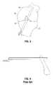
- FIG. 4is a side view of a conventional “over-the-top” femoral guide
- FIG. 5is side view of a knee joint including the “over-the-top” femoral guide of FIG. 4 accessing the femur using the trans-tibial approach;
- FIG. 6is a side view of a knee joint including the “over-the-top” femoral guide of FIG. 4 access the femur using the medial portal approach;
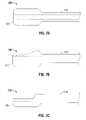
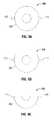
- FIGS. 7A-7Care side views of the distal end of various embodiments of a femoral guide according to the present disclosure.
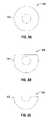
- FIGS. 8A-8Care end views of the distal end of the embodiments of FIGS. 7A-7C , respectively;
- FIGS. 9A-9Care end views of the distal end of alternative embodiments of a femoral guide according to the present disclosure.
- FIG. 10Ais a side view of a distal end of a femoral guide according to another embodiment of the present disclosure.
- FIG. 10Bis an end view of the distal end of the femoral guide of FIG. 10A ;
- FIG. 10Cis a side view of the femoral guide of FIGS. 10A and 10B ;
- FIG. 10Dis an end view of the femoral guide of FIGS. 10A-10C ;
- FIG. 10Eis top view of the distal end of the femoral guide of FIGS. 10A-10D ;
- FIG. 11is a partial cut-away view of a femoral guide according to an embodiment of the present disclosure being used in a medial portal approach;
- FIG. 12is a partial cut-away view of a femoral guide according to an embodiment of the present disclosure being used in a trans-tibial approach;
- FIG. 13is a side view of the proximal end of a femoral guide according to an embodiment of the present disclosure.
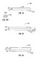
- FIG. 14is a perspective view of a femoral tunnel positioning guide according to another embodiment of the present disclosure.
- FIG. 14 ais an end view of an alternative embodiment of the present disclosure, showing first and second lumen having different cross-sectional shapes and sizes;
- FIG. 15is a side view of the femoral tunnel positioning guide according to another embodiment of the present disclosure.
- FIG. 16is a front view of the femoral tunnel positioning guide according to another embodiment of the present disclosure.
- the femoral guide of the present disclosureis designed to be used in determining the position of a femoral tunnel guide wire which facilitates the positioning of a femoral tunnel during an ACL reconstruction.
- the femoral guide of the present disclosuremay reference an “over-the-top” position with an offset spatula; however, it can also be designed and utilized without such an offset spatula. This includes having no spatula, or instead having one or multiple spike projections or other similar projections to hold the spatula in position on the bone.
- FIGS. 7A-10Eshow various embodiments of a femoral guide 100 formed in accordance with the present disclosure.
- Femoral guide 100generally includes a distal tip 105 and a shaft 110 extending proximally therefrom.
- Distal tip 105 of femoral guide 100may be dimensioned and configured to have the same geometry and circumference as the desired resulting femoral tunnel. In this manner, distal tip 105 acts as a visual aid to assist the surgeon in determining proper tunnel placement by providing a direct visual confirmation of where the resulting femoral tunnel will be located.
- distal tip 105may be formed with a semi-hemispherical cross-section ( FIGS. 7B , 8 B and 9 B), or with an “unroofed” cross-section ( FIGS. 7C , 8 C, 9 C and 10 A-E) to aid in visualization.
- Shaft 110 of femoral guide 100is configured to be of such a length so as to at least extend (i) across the knee joint, (ii) across the length of the tibial tunnel and/or (iii) out of the medial portal.
- Shaft 110 and distal tip 105are cannulated so as to accept (and thereby aim) a guidewire of an appropriate circumference, length and width.
- distal end 105 of femoral guide 100may include (i) diametrically-opposed fingers 115 ( FIGS. 9A-9C ), and/or (ii) a distal projection 120 ( FIGS. 10A-10E ).
- Fingers 115 and/or projection 120serve to reference the leading edge of the posterior cruciate ligament (PCL) and the posterior femoral cortex.
- PCLposterior cruciate ligament
- Using the PCL as an anatomical referenceenables a surgeon to set the femoral guide wire, and therefore the resulting femoral tunnel, in a position that better avoids any impingement of the PCL after the graft ligament has been placed in position.
- Such ACL/PCL impingementoccurs when the femoral tunnel has been improperly positioned.
- femoral guide 100is configured to avoid any such ACL/PCL impingement, by using the PCL as an anatomical reference during formation of the femoral tunnel.
- femoral guide 100may be used in a medial portal approach with the knee in hyper-flexion, at approximately 120 degrees. However, it should be appreciated that femoral guide 100 may also be used with any ACL reconstruction approach, and with any angle of knee flexion. See, for example, FIG. 12 , where femoral guide 100 is used during a traditional trans-tibial approach. Because of the size and/or configuration of distal end 105 of femoral guide 100 , for use in the trans-tibial approach, femoral guide 100 may be halved, with one half for use with the right knee and the other half for use with the left knee.
- guide wire 30( FIG. 11 ) is extended through the cannulated shaft of elongated shaft 110 and into femur 15 .
- guide wires 30has been inserted into femur 15 to a desired depth, femoral guide 100 is then removed from about guide wire 30 and from the medial portal into the knee.
- a cannulated drill bit(not shown) is then received about guide wire 30 and through the medial portal to drill femoral tunnel 25 .
- proximal (or “butt”) end 125 of femoral guide 100is preferably provided with a docking port 130 to mate with a handle 135 to aid the surgeon in aiming the guide more easily and accurately.
- Handle 135may be configured in any desired geometry so as to be ergonomically comfortable and/or to facilitate in the placement or holding of distal tip 105 in a particular position.
- Femoral guide 100provides surgeons with several significant improvements over prior art femoral guides.
- the distal portion of femoral guide 100is configured (both in shape and diameter), to mirror that of the resulting tunnel and, therefore, the resulting graft. This gives the surgeon a visual “preview” or reference of the femoral tunnel prior to actually drilling the femoral tunnel.
- the distal shape of the femoral guidereferences the leading edge of the PCL's insertion onto the femur (i.e., the location where the PCL attaches to the femur) and places the resulting femoral tunnel in a position which avoids graft ACL/PCL impingement.
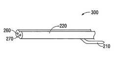
- FIG. 14illustrates an example embodiment of a femoral tunnel positioning device 300 having an arrangement in which the cannulated shaft 220 defines multiple guide wire lumen extending longitudinally therethrough.
- FIG. 14illustrate an example embodiment of the present invention having an arrangement in which the cannulated shaft 220 defines a first guide wire lumen 260 and a second guide wire lumen 270 extending longitudinally therethrough.
- the cannulated shaft 220defines multiple guide wire lumen extending longitudinally therethrough may provide additional advantages as compared to embodiments in which the cannulated shaft 220 defines a single guide wire lumen extending longitudinally therethrough.
- the cannulated shaft 220is configured to receive a single size and/or shape of guide wire (while the figures provided illustrate the lumen having a generally circular cross-sectional shape, it should be recognized that any conceivable shape may be employed, e.g., triangular, square, octagonal, etc.).
- a first guide wire lumen 260 adefines a triangular cross-sectional shape and a second guide wire lumen 270 a defines a square cross-sectional shape.
- Each of lumens 260 a and 270 aare also of different sizes. If a guide wire having a size and/or cross-sectional shape that is different from the lumen defined by the cannulated shaft 220 is attempted to be used, the cannulated shaft 220 may be unable to accommodate such irregular size and/or cross-sectional shape. In contrast, providing an arrangement in which the cannulated shaft 220 defines multiple guide wire lumen extending longitudinally therethrough may overcome some of these difficulties.
- the cannulated shaft 220may have lumen of differing sizes and/or shapes.
- the surgeonis not limited to using a single size and/or cross-sectional shape of guide wire, but rather may opt to utilize guide wires having various sizes and/or cross-sectional shapes.
- the centerline of the lumen of the cannulated shaft 220is typically configured to be vertically oriented relative to the distal offset projection 210 .
- Such an arrangementmay limit a surgeon to a single femoral tunnel position when the distal offset projection has been positioned against a surface of the femur, e.g., the posterior femoral notch.
- having an arrangement in which the multiple guide wire lumen defined by the cannulated shaft 220 are arranged in side-by-side relationship relative to each othermay enable a surgeon to select from various vertical alignments during the course of the surgical procedure. For example, if a surgeon determines, after the distal offset projection 210 has been positioned against a surface of the femur, e.g., the posterior femoral notch, that a guide wire placed through a first lumen 260 would provide a femoral tunnel position that is undesirable, the surgeon may then select to remove the guide wire from the first lumen 260 and to instead insert the guide wire through the second lumen 270 in order to achieve a femoral tunnel position that more desirable.
- Such adjustabilitymay be advantageous for many reasons, e.g., to accommodate variations in different patients' anatomy, to avoid anatomical features within the patient's knee, to accommodate particular surgeon preferences with respect to the best tunnel positions, etc.
- the femoral tunnel positioning device 300may provide indicia that provide an indication to the surgeon of the size and/or shape of the various lumens defined thereby.
- the present inventionincludes an arrangement in which the multiple guide wire lumen defined by the cannulated shaft 220 are arranged in side-by-side relationship relative to each other (e.g., whereby a distance between a centerline of each lumen and the distal offset projection is the same for each lumen), it should be recognized that the present invention may also include other embodiments in which the multiple guide wire lumen defined by the cannulated shaft 220 are not arranged in side-by-side relationship relative to each other. For example, FIG.
- FIG. 15is a perspective view of a femoral tunnel positioning device 400 that illustrates an example embodiment of the present invention having an arrangement in which the multiple guide wire lumen defined by the cannulated shaft 220 are not arranged in side-by-side relationship relative to each other.
- FIG. 15illustrates an example embodiment of the present invention having an arrangement in which the multiple guide wire lumen defined by the cannulated shaft 220 are not arranged in side-by-side relationship relative to each other, but rather are arranged in vertical relationship relative to each other.
- a distance between a centerline of the first lumen and the distal offset projection, and a distance between a centerline of the second lumen and the distal offset projectionmay be different relative to each other.
- FIG. 15is a perspective view of a femoral tunnel positioning device 400 that illustrates an example embodiment of the present invention having an arrangement in which the multiple guide wire lumen defined by the cannulated shaft 220 are not arranged in side-by-side relationship relative to each other, but rather are arranged in
- the distance between the longitudinal axis of the first lumen 270 of the cannulated shaft 220 and the distal offset projection 210is shown as d 1
- the distance between the longitudinal axis of the second lumen 260 of the cannulated shaft 220 and the distal offset projection 210is shown as d 2
- d 2being greater than d 1 .
- This increase in the distancemay preferably be from 0 to about 4 mm, although any increase in this distance is contemplated.
- Providing an arrangement in which the multiple guide wire lumen defined by the cannulated shaft 220 are arranged in vertical relationship relative to each other, e.g., such that each lumen is offset from the distal offset projection by a different amount,may provide additional advantages as compared to embodiments in which the cannulated shaft defines a single lumen extending longitudinally therethrough.
- having an arrangement in which the cannulated shaft 220 defines multiple guide wire lumen extending longitudinally therethroughmay enable the use of different size and/or shape lumen, and thus a surgeon is not limited to using a single size and/or cross-sectional shape of guide wire.
- providing an arrangement in which the multiple guide wire lumen defined by the cannulated shaft 220 are arranged in vertical relationship relative to each other, e.g., such that each lumen is offset from the distal offset projection by a different amount,may provide additional advantages as compared to embodiments in which the multiple guide wire lumen defined by the cannulated shaft 220 are arranged in side-by-side relationship relative to each other and in which the cannulated shaft 220 defines a single lumen extending longitudinally therethrough.
- the distance between a centerline of each lumen and the distal offset projectionis the same for each lumen.
- Such an arrangementmay limit a surgeon to a single femoral tunnel position when the distal offset projection has been positioned against a surface of the femur, e.g., the posterior femoral notch.
- having an arrangement in which the multiple guide wire lumen defined by the cannulated shaft 220 are arranged in vertical relationship relative to each othermay enable a surgeon to select from various offset distances during the course of the surgical procedure. For example, if a surgeon determines, after the distal offset projection 210 has been positioned against a surface of the femur, e.g., the posterior femoral notch, that a guide wire placed through a first lumen 260 is providing a femoral tunnel position that is undesirable (e.g., too posterior or too anterior), the surgeon may then select to remove the guide wire from the first lumen 260 and to instead insert the guide wire through the second lumen 270 in order to achieve a femoral tunnel position that more desirable.
- Such adjustabilitymay be advantageous for many reasons, e.g., to accommodate variations in different patients' anatomy, to avoid anatomical features within the patient's knee, to accommodate particular surgeon preferences with respect to the best tunnel positions, etc.
- FIG. 16is a perspective view of a femoral tunnel positioning device 500 that illustrates an example embodiment of the present invention having an arrangement in which the cannulated shaft 220 defines more than two, e.g., three, lumen extending longitudinally therethrough.
- FIG. 16is a perspective view of a femoral tunnel positioning device 500 that illustrates an example embodiment of the present invention having an arrangement in which the cannulated shaft 220 defines more than two, e.g., three, lumen extending longitudinally therethrough.
- FIG. 16illustrates an example embodiment of the present invention having an arrangement in which the cannulated shaft 220 defines a first lumen 260 , a second lumen 270 and a third lumen 280 extending longitudinally therethrough.
- the present inventioncontemplates any desirable relative position of the various lumen, in the embodiment shown in FIG. 16 , the first and second lumen 260 , 270 are arranged in side-by-side relationship relative to each other, and in non-vertical relationship relative to the distal offset projection 210 .
- the third lumen 28is arranged in vertical relationship relative to the distal offset projection 210 .
- the offset distances between the distal offset projection 210 and the first and second lumen 260 , 270are greater than the offset distance between the distal offset projection 210 and the third lumen 280 .
- the surgeonmay have the ability to choose from various lumen, and thus from various femoral tunnel positions, during the course of a surgical procedure.
Landscapes
- Health & Medical Sciences (AREA)
- Surgery (AREA)
- Life Sciences & Earth Sciences (AREA)
- Orthopedic Medicine & Surgery (AREA)
- Biomedical Technology (AREA)
- Molecular Biology (AREA)
- Oral & Maxillofacial Surgery (AREA)
- Engineering & Computer Science (AREA)
- Dentistry (AREA)
- Heart & Thoracic Surgery (AREA)
- Medical Informatics (AREA)
- Nuclear Medicine, Radiotherapy & Molecular Imaging (AREA)
- Animal Behavior & Ethology (AREA)
- General Health & Medical Sciences (AREA)
- Public Health (AREA)
- Veterinary Medicine (AREA)
- Rheumatology (AREA)
- Surgical Instruments (AREA)
Abstract
Description
Claims (10)
Priority Applications (2)
| Application Number | Priority Date | Filing Date | Title |
|---|---|---|---|
| US12/548,791US8343161B2 (en) | 2008-02-21 | 2009-08-27 | Femoral guide for ACL repair having multiple lumen |
| PCT/US2010/046769WO2011025863A1 (en) | 2009-08-27 | 2010-08-26 | Femoral guide for acl repair having multiple lumen |
Applications Claiming Priority (4)
| Application Number | Priority Date | Filing Date | Title |
|---|---|---|---|
| US6657508P | 2008-02-21 | 2008-02-21 | |
| US6657208P | 2008-02-21 | 2008-02-21 | |
| US12/366,967US20090216243A1 (en) | 2008-02-21 | 2009-02-06 | Guide for creating femoral tunnel during acl reconstruction |
| US12/548,791US8343161B2 (en) | 2008-02-21 | 2009-08-27 | Femoral guide for ACL repair having multiple lumen |
Related Parent Applications (1)
| Application Number | Title | Priority Date | Filing Date |
|---|---|---|---|
| US12/366,967Continuation-In-PartUS20090216243A1 (en) | 2008-02-21 | 2009-02-06 | Guide for creating femoral tunnel during acl reconstruction |
Publications (2)
| Publication Number | Publication Date |
|---|---|
| US20100049201A1 US20100049201A1 (en) | 2010-02-25 |
| US8343161B2true US8343161B2 (en) | 2013-01-01 |
Family
ID=43628381
Family Applications (1)
| Application Number | Title | Priority Date | Filing Date |
|---|---|---|---|
| US12/548,791Expired - Fee RelatedUS8343161B2 (en) | 2008-02-21 | 2009-08-27 | Femoral guide for ACL repair having multiple lumen |
Country Status (2)
| Country | Link |
|---|---|
| US (1) | US8343161B2 (en) |
| WO (1) | WO2011025863A1 (en) |
Cited By (6)
| Publication number | Priority date | Publication date | Assignee | Title |
|---|---|---|---|---|
| US20140031932A1 (en)* | 2009-03-31 | 2014-01-30 | Imds Corporation | Double bundle acl repair |
| US8968402B2 (en) | 2011-10-18 | 2015-03-03 | Arthrocare Corporation | ACL implants, instruments, and methods |
| US20160022285A1 (en)* | 2010-10-25 | 2016-01-28 | Smith & Nephew, Inc. | Oval tibia guide |
| US9826992B2 (en) | 2007-12-21 | 2017-11-28 | Smith & Nephew, Inc. | Multiple portal guide |
| US9888936B2 (en) | 2010-09-27 | 2018-02-13 | Smith & Nephew, Inc. | Device and methods for use during arthroscopic surgery |
| US10219812B2 (en) | 2010-11-03 | 2019-03-05 | Smith & Nephew, Inc. | Drill guide |
Families Citing this family (6)
| Publication number | Priority date | Publication date | Assignee | Title |
|---|---|---|---|---|
| US8956278B2 (en) | 2007-12-21 | 2015-02-17 | Smith & Nephew, Inc. | Multiple portal guide |
| CA2713309C (en)* | 2009-08-20 | 2013-07-02 | Howmedica Osteonics Corp. | Flexible acl instrumentation, kit and method |
| MX348238B (en)* | 2011-03-09 | 2017-05-29 | Smith & Nephew Inc | Multiple portal guide. |
| DE102011108673A1 (en)* | 2011-07-22 | 2013-01-24 | Karl Storz Gmbh & Co. Kg | Device for targeting and inserting several drill channels into a bone |
| US8790352B2 (en)* | 2011-10-03 | 2014-07-29 | Smith & Nephew, Inc. | Ovoid tunnel guide and method of ACL reconstruction |
| US10182808B2 (en) | 2015-04-23 | 2019-01-22 | DePuy Synthes Products, Inc. | Knotless suture anchor guide |
Citations (45)
| Publication number | Priority date | Publication date | Assignee | Title |
|---|---|---|---|---|
| EP0279129A1 (en)* | 1986-10-28 | 1988-08-24 | Cerol Bandeira, Maria de Lourdes | Device for attaching ligament or tendon prostheses having end loops to the bone, and a complete prostheses containing such a device |
| US4911153A (en) | 1988-02-04 | 1990-03-27 | Biomet, Inc. | Orthopedic surgical instrument |
| US5078719A (en)* | 1990-01-08 | 1992-01-07 | Schreiber Saul N | Osteotomy device and method therefor |
| US5147367A (en)* | 1991-02-22 | 1992-09-15 | Ellis Alfred B | Drill pin guide and method for orthopedic surgery |
| US5152764A (en) | 1992-05-18 | 1992-10-06 | Marlowe Goble E | Femoral tunnel entry drill guide |
| US5250055A (en) | 1992-06-08 | 1993-10-05 | Orthopedic Systems Inc. | Method and apparatus for tying suture to bone |
| US5306278A (en)* | 1992-09-11 | 1994-04-26 | Ace Medical Company | Corticotomy drill guide |
| US5314429A (en) | 1990-09-07 | 1994-05-24 | Marlowe Goble E | Method for forming a tunnel intersecting a straight cruciate ligament tunnel |
| US5320115A (en) | 1991-01-16 | 1994-06-14 | Applied Biological Concepts | Method and apparatus for arthroscopic knee surgery |
| US5320626A (en) | 1992-02-19 | 1994-06-14 | Arthrex Inc. | Endoscopic drill guide |
| US5445642A (en) | 1992-09-01 | 1995-08-29 | Depuy Inc. | Method for installing a femoral component |
| US5514144A (en) | 1993-12-20 | 1996-05-07 | Bolton; Carl W. | Drill guide device for the arthroscopic anatomic placement of a straight tibio-femoral bone tunnel for ACL reconstruction |
| US5520693A (en) | 1992-02-19 | 1996-05-28 | Mcguire; David A. | Femoral guide and methods of precisely forming bone tunnels in cruciate ligament reconstruction of the knee |
| US5562669A (en) | 1994-01-13 | 1996-10-08 | Mcguire; David A. | Cruciate ligament reconstruction with tibial drill guide |
| US5562664A (en) | 1992-02-20 | 1996-10-08 | Arthrex Inc. | Drill guide with target PCL-oriented marking hook |
| US5570706A (en) | 1990-07-16 | 1996-11-05 | Howell; Stephen M. | Method for ACL reconstruction |
| US5613971A (en) | 1995-08-11 | 1997-03-25 | Depuy Inc. | Ratcheting tibial and femoral guide |
| FR2744621A1 (en) | 1996-02-09 | 1997-08-14 | Lars | Tool used during the replacement of anterior cruciate ligament of the knee while under arthroscopy |
| US5891150A (en) | 1996-12-04 | 1999-04-06 | Chan; Kwan-Ho | Apparatus and method for fixing a ligament in a bone tunnel |
| US5968050A (en) | 1997-12-05 | 1999-10-19 | Smith & Nephew, Inc. | Positioning a tibial tunnel |
| US6022356A (en) | 1998-03-18 | 2000-02-08 | Smith & Nephew, Inc. | Cruciate ligament reconstruction template |
| US6096038A (en)* | 1988-06-13 | 2000-08-01 | Michelson; Gary Karlin | Apparatus for inserting spinal implants |
| US6254606B1 (en) | 1999-10-13 | 2001-07-03 | William P. Carney | Laser aiming device for performing anterior cruciate ligament reconstruction surgery and method for using same |
| US6309396B1 (en) | 1998-02-19 | 2001-10-30 | G. David Ritland | Tool for inserting an intramedullary guide wire |
| US20020151903A1 (en) | 2001-04-12 | 2002-10-17 | Asahi Kogaku Kogyo Kabushiki Kaisha | Surgical instrument |
| US20030145860A1 (en)* | 2001-12-21 | 2003-08-07 | Johnson Roger N. | Surface energy assisted fluid transport system |
| US20040267273A1 (en) | 2003-06-27 | 2004-12-30 | Whittaker Gregory R. | Adjustable drill guide assembly and method of use |
| US20050203523A1 (en) | 2004-03-05 | 2005-09-15 | Wenstrom Richard F.Jr. | Tunnel notcher and guidewire delivery device |
| US20050228399A1 (en) | 2004-04-12 | 2005-10-13 | Toshikazu Kubo | Guiding device for use in anterior cruciate knee ligament reconstruction |
| US20060074434A1 (en) | 2004-09-27 | 2006-04-06 | Wenstrom Richard F Jr | Triangular handle surgical drill guide |
| US7032599B2 (en) | 2003-05-15 | 2006-04-25 | Mitek Surgical Products Div. Of Ethicon, Inc. | Method of replacing an anterior cruciate ligament in the knee |
| US20060149283A1 (en) | 2004-12-21 | 2006-07-06 | May Thomas C | Method of replacing an anterior cruciate ligament in the knee |
| US20060293689A1 (en) | 2002-10-29 | 2006-12-28 | Stryker Endoscopy | Graft fixation device and method |
| US20070123902A1 (en) | 2005-04-22 | 2007-05-31 | Sascha Berberich | Device for forming a drill hole in bone |
| US20070191853A1 (en) | 2006-02-02 | 2007-08-16 | Arthrotek, Inc. | Method and apparatus for performing ACL reconstruction |
| US20070233151A1 (en) | 2006-02-02 | 2007-10-04 | Chudik Steven C | Universal anterior cruciate ligament repair and reconstruction system |
| US20070233128A1 (en) | 2005-11-10 | 2007-10-04 | Reinhold Schmieding | Method and apparatus for ACL reconstruction using retrograde cutter |
| US20080103506A1 (en) | 2006-10-30 | 2008-05-01 | Depuy Mitek, Inc. | Methods and devices for ligament repair |
| US20080234819A1 (en) | 2007-02-15 | 2008-09-25 | Reinhold Schmieding | All-inside double-bundle acl reconstruction |
| US20090018654A1 (en) | 2007-06-29 | 2009-01-15 | Reinhold Schmieding | Double socket acl reconstruction |
| US20090030417A1 (en) | 2007-07-17 | 2009-01-29 | Toshiaki Takahashi | Drill guide for anterior cruciate ligament reconstruction operation |
| US20090157081A1 (en) | 2007-12-17 | 2009-06-18 | Bradley Michael Homan | Surgical Drill For Providing Holes At An Angle |
| US20090187244A1 (en) | 2008-01-21 | 2009-07-23 | Brian Dross | Method of arthroscopically assisted ligament reconstruction |
| CA2654486A1 (en) | 2008-02-21 | 2009-08-21 | Tyco Healthcare Group Lp | Guide for creating femoral tunnel during acl reconstruction |
| US20090265003A1 (en) | 2001-10-01 | 2009-10-22 | Scandius Biomedical, Inc. | Apparatus and method for reconstructing a ligament |
- 2009
- 2009-08-27USUS12/548,791patent/US8343161B2/ennot_activeExpired - Fee Related
- 2010
- 2010-08-26WOPCT/US2010/046769patent/WO2011025863A1/enactiveApplication Filing
Patent Citations (52)
| Publication number | Priority date | Publication date | Assignee | Title |
|---|---|---|---|---|
| EP0279129A1 (en)* | 1986-10-28 | 1988-08-24 | Cerol Bandeira, Maria de Lourdes | Device for attaching ligament or tendon prostheses having end loops to the bone, and a complete prostheses containing such a device |
| US4911153A (en) | 1988-02-04 | 1990-03-27 | Biomet, Inc. | Orthopedic surgical instrument |
| US6096038A (en)* | 1988-06-13 | 2000-08-01 | Michelson; Gary Karlin | Apparatus for inserting spinal implants |
| US5078719A (en)* | 1990-01-08 | 1992-01-07 | Schreiber Saul N | Osteotomy device and method therefor |
| US5570706A (en) | 1990-07-16 | 1996-11-05 | Howell; Stephen M. | Method for ACL reconstruction |
| US5385567A (en) | 1990-09-07 | 1995-01-31 | Goble; E. Marlowe | Sight barrel arthroscopic instrument |
| US5314429A (en) | 1990-09-07 | 1994-05-24 | Marlowe Goble E | Method for forming a tunnel intersecting a straight cruciate ligament tunnel |
| US5320115A (en) | 1991-01-16 | 1994-06-14 | Applied Biological Concepts | Method and apparatus for arthroscopic knee surgery |
| US5147367A (en)* | 1991-02-22 | 1992-09-15 | Ellis Alfred B | Drill pin guide and method for orthopedic surgery |
| US6878150B1 (en) | 1992-02-19 | 2005-04-12 | Mcguire David A. | Methods of precisely forming bone tunnels in cruciate ligament reconstruction of the knee |
| US5320626A (en) | 1992-02-19 | 1994-06-14 | Arthrex Inc. | Endoscopic drill guide |
| US20030009173A1 (en) | 1992-02-19 | 2003-01-09 | Mcguire David A. | Femoral guide and methods of precisely forming bone tunnels in cruciate ligament reconstruction of the knee |
| US6352538B2 (en) | 1992-02-19 | 2002-03-05 | Mcguire David A. | Femoral guide and methods of precisely forming bone tunnels in cruciate ligament reconstruction of the knee |
| US5520693A (en) | 1992-02-19 | 1996-05-28 | Mcguire; David A. | Femoral guide and methods of precisely forming bone tunnels in cruciate ligament reconstruction of the knee |
| US7025770B2 (en) | 1992-02-19 | 2006-04-11 | Mcguire David A | Femoral guide and methods of precisely forming bone tunnels in cruciate ligament reconstruction of the knee |
| US5562664A (en) | 1992-02-20 | 1996-10-08 | Arthrex Inc. | Drill guide with target PCL-oriented marking hook |
| US5152764A (en) | 1992-05-18 | 1992-10-06 | Marlowe Goble E | Femoral tunnel entry drill guide |
| US5250055A (en) | 1992-06-08 | 1993-10-05 | Orthopedic Systems Inc. | Method and apparatus for tying suture to bone |
| US5445642A (en) | 1992-09-01 | 1995-08-29 | Depuy Inc. | Method for installing a femoral component |
| US5306278A (en)* | 1992-09-11 | 1994-04-26 | Ace Medical Company | Corticotomy drill guide |
| US5514144A (en) | 1993-12-20 | 1996-05-07 | Bolton; Carl W. | Drill guide device for the arthroscopic anatomic placement of a straight tibio-femoral bone tunnel for ACL reconstruction |
| US5562669A (en) | 1994-01-13 | 1996-10-08 | Mcguire; David A. | Cruciate ligament reconstruction with tibial drill guide |
| US5613971A (en) | 1995-08-11 | 1997-03-25 | Depuy Inc. | Ratcheting tibial and femoral guide |
| FR2744621A1 (en) | 1996-02-09 | 1997-08-14 | Lars | Tool used during the replacement of anterior cruciate ligament of the knee while under arthroscopy |
| US5891150A (en) | 1996-12-04 | 1999-04-06 | Chan; Kwan-Ho | Apparatus and method for fixing a ligament in a bone tunnel |
| US5968050A (en) | 1997-12-05 | 1999-10-19 | Smith & Nephew, Inc. | Positioning a tibial tunnel |
| US6309396B1 (en) | 1998-02-19 | 2001-10-30 | G. David Ritland | Tool for inserting an intramedullary guide wire |
| US6022356A (en) | 1998-03-18 | 2000-02-08 | Smith & Nephew, Inc. | Cruciate ligament reconstruction template |
| US6254606B1 (en) | 1999-10-13 | 2001-07-03 | William P. Carney | Laser aiming device for performing anterior cruciate ligament reconstruction surgery and method for using same |
| US20020151903A1 (en) | 2001-04-12 | 2002-10-17 | Asahi Kogaku Kogyo Kabushiki Kaisha | Surgical instrument |
| US20090265003A1 (en) | 2001-10-01 | 2009-10-22 | Scandius Biomedical, Inc. | Apparatus and method for reconstructing a ligament |
| US20030145860A1 (en)* | 2001-12-21 | 2003-08-07 | Johnson Roger N. | Surface energy assisted fluid transport system |
| US20060293689A1 (en) | 2002-10-29 | 2006-12-28 | Stryker Endoscopy | Graft fixation device and method |
| US7032599B2 (en) | 2003-05-15 | 2006-04-25 | Mitek Surgical Products Div. Of Ethicon, Inc. | Method of replacing an anterior cruciate ligament in the knee |
| US7491206B2 (en) | 2003-06-27 | 2009-02-17 | Ethicon, Inc. | Adjustable drill guide assembly and method of use |
| US20040267273A1 (en) | 2003-06-27 | 2004-12-30 | Whittaker Gregory R. | Adjustable drill guide assembly and method of use |
| US20050203523A1 (en) | 2004-03-05 | 2005-09-15 | Wenstrom Richard F.Jr. | Tunnel notcher and guidewire delivery device |
| US20050228399A1 (en) | 2004-04-12 | 2005-10-13 | Toshikazu Kubo | Guiding device for use in anterior cruciate knee ligament reconstruction |
| US20060074434A1 (en) | 2004-09-27 | 2006-04-06 | Wenstrom Richard F Jr | Triangular handle surgical drill guide |
| US20060149283A1 (en) | 2004-12-21 | 2006-07-06 | May Thomas C | Method of replacing an anterior cruciate ligament in the knee |
| US7458975B2 (en) | 2004-12-21 | 2008-12-02 | Johnson & Johnson | Method of replacing an anterior cruciate ligament in the knee |
| US20070123902A1 (en) | 2005-04-22 | 2007-05-31 | Sascha Berberich | Device for forming a drill hole in bone |
| US20070233128A1 (en) | 2005-11-10 | 2007-10-04 | Reinhold Schmieding | Method and apparatus for ACL reconstruction using retrograde cutter |
| US20070191853A1 (en) | 2006-02-02 | 2007-08-16 | Arthrotek, Inc. | Method and apparatus for performing ACL reconstruction |
| US20070233151A1 (en) | 2006-02-02 | 2007-10-04 | Chudik Steven C | Universal anterior cruciate ligament repair and reconstruction system |
| US20080103506A1 (en) | 2006-10-30 | 2008-05-01 | Depuy Mitek, Inc. | Methods and devices for ligament repair |
| US20080234819A1 (en) | 2007-02-15 | 2008-09-25 | Reinhold Schmieding | All-inside double-bundle acl reconstruction |
| US20090018654A1 (en) | 2007-06-29 | 2009-01-15 | Reinhold Schmieding | Double socket acl reconstruction |
| US20090030417A1 (en) | 2007-07-17 | 2009-01-29 | Toshiaki Takahashi | Drill guide for anterior cruciate ligament reconstruction operation |
| US20090157081A1 (en) | 2007-12-17 | 2009-06-18 | Bradley Michael Homan | Surgical Drill For Providing Holes At An Angle |
| US20090187244A1 (en) | 2008-01-21 | 2009-07-23 | Brian Dross | Method of arthroscopically assisted ligament reconstruction |
| CA2654486A1 (en) | 2008-02-21 | 2009-08-21 | Tyco Healthcare Group Lp | Guide for creating femoral tunnel during acl reconstruction |
Non-Patent Citations (1)
| Title |
|---|
| PCT International Search Reports dated Oct. 19, 2010 for the corresponding application PCT/US2010/046764, Oct. 25, 2010 for the corresponding application PCT/US2010/046774, Oct. 26, 2010 for the corresponding application PCT/US2010/046769, and Oct. 27, 2010 for the corresponding application PCT/US2010/046804. |
Cited By (9)
| Publication number | Priority date | Publication date | Assignee | Title |
|---|---|---|---|---|
| US9826992B2 (en) | 2007-12-21 | 2017-11-28 | Smith & Nephew, Inc. | Multiple portal guide |
| US20140031932A1 (en)* | 2009-03-31 | 2014-01-30 | Imds Corporation | Double bundle acl repair |
| US9216079B2 (en)* | 2009-03-31 | 2015-12-22 | Imds Llc | Double bundle ACL repair |
| US9549811B2 (en) | 2009-03-31 | 2017-01-24 | Imds Llc | Double bundle ACL repair |
| US9888936B2 (en) | 2010-09-27 | 2018-02-13 | Smith & Nephew, Inc. | Device and methods for use during arthroscopic surgery |
| US20160022285A1 (en)* | 2010-10-25 | 2016-01-28 | Smith & Nephew, Inc. | Oval tibia guide |
| US9579111B2 (en)* | 2010-10-25 | 2017-02-28 | Smith & Nephew, Inc. | Oval tibia guide |
| US10219812B2 (en) | 2010-11-03 | 2019-03-05 | Smith & Nephew, Inc. | Drill guide |
| US8968402B2 (en) | 2011-10-18 | 2015-03-03 | Arthrocare Corporation | ACL implants, instruments, and methods |
Also Published As
| Publication number | Publication date |
|---|---|
| US20100049201A1 (en) | 2010-02-25 |
| WO2011025863A1 (en) | 2011-03-03 |
Similar Documents
| Publication | Publication Date | Title |
|---|---|---|
| US8343161B2 (en) | Femoral guide for ACL repair having multiple lumen | |
| EP2092901B1 (en) | Guide for creating femoral tunnel during ACL reconstruction | |
| US8430883B2 (en) | Femoral guide for ACL repair having reduced profile for left/right knee configurations | |
| US8282647B2 (en) | Femoral guide for ACL repair having adjustable offset | |
| US7842042B2 (en) | Convergent tunnel guide apparatus and method | |
| US8430884B2 (en) | Femoral guide for ACL repair having selectively deployable femoral surface engagement member | |
| CA2637682C (en) | Tunnel notcher and guidewire delivery device | |
| US8323289B2 (en) | Tibial guide for ACL repair having left/right docking configuration | |
| US8292894B2 (en) | Device for orienting the tibial tunnel position during an ACL reconstruction | |
| US9795398B2 (en) | Flexible ACL instrumentation, kit and method | |
| US11980375B2 (en) | Anterior cruciate ligament reconstruction | |
| US20100049198A1 (en) | Tibial guide for acl repair having off-axis guide wire arrangement |
Legal Events
| Date | Code | Title | Description |
|---|---|---|---|
| AS | Assignment | Owner name:TYCO HEALTHCARE GROUP LP,CONNECTICUT Free format text:ASSIGNMENT OF ASSIGNORS INTEREST;ASSIGNOR:RE, PAUL, MD;REEL/FRAME:023157/0229 Effective date:20090209 Owner name:TYCO HEALTHCARE GROUP LP, CONNECTICUT Free format text:ASSIGNMENT OF ASSIGNORS INTEREST;ASSIGNOR:RE, PAUL, MD;REEL/FRAME:023157/0229 Effective date:20090209 | |
| AS | Assignment | Owner name:COVIDIEN LP, MASSACHUSETTS Free format text:CHANGE OF NAME;ASSIGNOR:TYCO HEALTHCARE GROUP LP;REEL/FRAME:029065/0448 Effective date:20120928 | |
| STCF | Information on status: patent grant | Free format text:PATENTED CASE | |
| FPAY | Fee payment | Year of fee payment:4 | |
| FEPP | Fee payment procedure | Free format text:MAINTENANCE FEE REMINDER MAILED (ORIGINAL EVENT CODE: REM.); ENTITY STATUS OF PATENT OWNER: LARGE ENTITY | |
| LAPS | Lapse for failure to pay maintenance fees | Free format text:PATENT EXPIRED FOR FAILURE TO PAY MAINTENANCE FEES (ORIGINAL EVENT CODE: EXP.); ENTITY STATUS OF PATENT OWNER: LARGE ENTITY | |
| STCH | Information on status: patent discontinuation | Free format text:PATENT EXPIRED DUE TO NONPAYMENT OF MAINTENANCE FEES UNDER 37 CFR 1.362 | |
| FP | Lapsed due to failure to pay maintenance fee | Effective date:20210101 |