US8343149B2 - Deployable microwave antenna for treating tissue - Google Patents
Deployable microwave antenna for treating tissueDownload PDFInfo
- Publication number
- US8343149B2 US8343149B2US12/147,093US14709308AUS8343149B2US 8343149 B2US8343149 B2US 8343149B2US 14709308 AUS14709308 AUS 14709308AUS 8343149 B2US8343149 B2US 8343149B2
- Authority
- US
- United States
- Prior art keywords
- antennas
- assembly
- antenna
- tissue
- ablation
- Prior art date
- Legal status (The legal status is an assumption and is not a legal conclusion. Google has not performed a legal analysis and makes no representation as to the accuracy of the status listed.)
- Expired - Fee Related, expires
Links
Images


Classifications
- A—HUMAN NECESSITIES
- A61—MEDICAL OR VETERINARY SCIENCE; HYGIENE
- A61B—DIAGNOSIS; SURGERY; IDENTIFICATION
- A61B18/00—Surgical instruments, devices or methods for transferring non-mechanical forms of energy to or from the body
- A61B18/18—Surgical instruments, devices or methods for transferring non-mechanical forms of energy to or from the body by applying electromagnetic radiation, e.g. microwaves
- A61B18/1815—Surgical instruments, devices or methods for transferring non-mechanical forms of energy to or from the body by applying electromagnetic radiation, e.g. microwaves using microwaves
Definitions
- the present disclosurerelates generally to a microwave antenna that can treat tissue. More particularly, the present disclosure is directed to a microwave antenna suitable for use in resection of tissue.
- Treatment of certain diseasesrequires destruction of malignant tissue growths (e.g., tumors) or surrounding tissue. It is known that tumor cells denature at elevated temperatures that are slightly lower than temperatures injurious to surrounding healthy cells. Therefore, known treatment methods, such as hyperthermia therapy, heat tumor cells to temperatures above 41° C., while maintaining adjacent healthy cells at lower temperatures to avoid irreversible cell damage. Such methods involve applying electromagnetic radiation to heat, ablate and/or coagulate tissue. Microwave energy is sometimes utilized to perform these methods. In particular, microwave energy is used to coagulate or ablate tissue. Another method used to treat diseased tissue is to resect a portion of the diseased organ, tissue or anatomical structure. For example, a liver may contain diseased tissue and healthy tissue.
- One treatment optionis to pre-coagulate and ablate some of the liver tissue to facilitate resection of a portion of the liver including the diseased tissue.
- Microwave energycan be used during these types of procedures to pre-coagulate tissue prior to resection, to reduce bleeding during resection and to facilitate the actual resection of the tissue.
- the microwave energymay be applied via antennas that can penetrate tissue.
- microwave antennasThere are several types of microwave antennas, such as monopole and dipole antennas. In monopole and dipole antennas, most of the microwave energy radiates perpendicularly away from the axis of the conductor.
- a monopole antennaincludes a single, elongated conductor that transmits the microwave energy.
- a typical dipole antennahas two elongated conductors parallel to each other and positioned end-to-end relative to one another with an insulator placed therebetween. Each of the conductors is typically about 1 ⁇ 4 of the length of the wavelength of the microwave energy making the aggregate length of both conductors about 1 ⁇ 2 of the wavelength of the microwave energy.
- a coaxial dipole antennatypically includes a first elongated conductor and a second elongated conductor disposed concentrically around the first elongated conductor along about half of the distance of the coaxial assembly.
- the portion having the second elongated conductoris about 1 ⁇ 4 of a wavelength and the portion having only the first elongated conductor is also about 1 ⁇ 4 of a wavelength, making the aggregate length of the antenna about a 1 ⁇ 2 wavelength.
- Some microwave antennashave a narrow operational bandwidth, a wavelength range at which operational efficiency is achieved, and hence, are incapable of maintaining a predetermined impedance match between the microwave delivery system (e.g., generator, cable, etc.) and the tissue surrounding the microwave antenna. More specifically, as microwave energy is applied to tissue, the dielectric constant of the tissue immediately surrounding the microwave antenna decreases as the tissue is heated. This drop may cause the optimal microwave energy wavelength to change beyond the bandwidth of the antenna. As a result, there may be a mismatch between the bandwidth of conventional microwave antennas and the microwave energy being applied.
- the microwave delivery systeme.g., generator, cable, etc.
- the present disclosurerelates generally to a microwave antenna that can treat tissue. More particularly, the present disclosure is directed to a microwave antenna suitable for use in resection of tissue.
- a microwave ablation system for treating tissueincludes an assembly of antennas.
- the antennas of the assembly of antennasconnect to a microwave generator that is configured to generate microwave energy.
- Each antenna of the assembly of antennasincludes inner and outer conductors.
- the inner conductorhas a length.
- the outer conductorhas a longitudinal axis defined along a length thereof.
- the outer conductorat least partially surrounds the inner conductor at least partially along a length thereof.
- One of the inner and outer conductorsis movable with respect to the other.
- a tapered endis disposed at the distal end of the inner conductor and/or the outer conductor.
- a dielectric material layeris at least partially disposed between the inner and outer conductor.
- At least one antenna of the assembly of antennasis deployable from a first state to a second deployable state.
- the first stateablates a first ablation region of tissue and the second deployable state ablates a second ablation region of tissue.
- the first and second ablation tissue regionsmay overlap to define an aggregate ablation region.
- At least two of the assembly of antennashas two overlapping aggregate ablation regions to at least partially form an ablation plane.
- Two or more antennas of the assembly of antennasmay have parallel longitudinal axes.
- the longitudinal axes of the assembly of antennasmay be approximately parallel.
- the longitudinal axes of the assembly of antennasmay be disposed in a planar region.
- each of the aggregate ablation regions of each of the assembly of antennasoverlaps to at least partially form a curved plane.
- the assembly of antennasmay be positioned to form, at least partially, a concentric ablation plane.
- the systemfurther includes a connection hub.
- the connection hubmay include multiple cable connectors and each of the cable connectors is coupled to each corresponding antenna of the assembly of antennas.
- the connection hubmay include a cable connector and a semi-rigid coaxial cable. The semi-rigid coaxial cable is coupled to an antenna of the assembly of antennas and to the cable connector.
- connection hubin another embodiment, includes a cable connector; which is coupled to each antenna of the assembly of antennas.
- the connection hubfurther includes a power splitter coupled to the cable connector and to each antenna of the assembly of antennas.
- the power splitteris configured to direct a predetermined quantity of the microwave energy to each antenna of the assembly of antennas.
- the systemincludes a microwave generator, which generates microwave energy at a plurality of wavelengths.
- Each antenna of the assembly of antennashas an effective wavelength that is about equal to a corresponding wavelength of the plurality of wavelengths.
- an antenna of the assembly of antennashas a variable effective wavelengths and the microwave generator varies the first wavelength to be about equal to the variable effective wavelength of the antenna of the assembly of antennas.
- a method of treating tissueincludes the step of providing an antenna.
- the methodalso includes deploying the antenna to a first state and ablating a first ablation regions.
- the methoddeploys the antenna to a second deployable state and ablates a second region.
- the first and second ablation regionsoverlap to define an aggregate ablation region.
- the step of deploying the antenna to the first state mid the step of ablating the first ablation regionmay be staggered or may occur sequentially.
- the microwave energycan be delivered to the tissue as the antenna is deployed from the first state to the second deployable state.
- the antennahas a variable effective wavelength and the microwave energy is varied to be about equal to the variable effective wavelength (this step may be skipped in some embodiments).
- an antennain yet another embodiment of the present disclosure, includes inner and outer conductors.
- the inner conductorincludes a length.
- the outer conductorhaving a longitudinal axis defined along a length thereof.
- the outer conductorat least partially surrounding the inner conductor at least partially along the length thereof.
- the inner conductor or outer conductoris movable with respect to the other.
- the antennais deployable from a first state for ablating a first ablation region of tissue to a second deployable state for ablating a second ablation region of tissue.
- the first and second ablation tissue regionsoverlap to define an aggregate ablation region.
- FIG. 1is a schematic diagram of a microwave system for treating tissue in accordance with the present disclosure
- FIG. 2is a block diagram of a microwave generator that can generate microwave energy for ablating tissue in accordance with the present disclosure
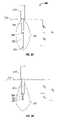
- FIG. 3Ais a schematic, side-view of a deployable antenna in situ that is in a balanced dipole deployment in accordance with the present disclosure
- FIGS. 3B and 3Cshow two schematic, side-views of the deployable antenna of FIG. 3A in situ that is in an unbalanced dipole deployment in accordance with the present disclosure
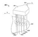
- FIGS. 4A and 4Bare schematic, side-views of a surgical instrument having an assembly of antennas connected to a connection hub with a single cable connector that forms an ablation plane in accordance with the present disclosure
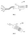
- FIG. 5shows a schematic, side-view of a surgical instrument having an assembly of antennas connected to a connection hub via a bundle of cables in accordance with the present disclosure
- FIG. 6shows a perspective view of a surgical instrument having an assembly of antennas each connected to a disc shaped connection hub in accordance with the present disclosure
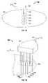
- FIG. 7Ashows a side view of a surgical instrument having an assembly of antennas ablating tissue to facilitate resection of tissue in accordance with the present disclosure
- FIG. 7Bshows a front-view of the surgical instrument of FIG. 8A in accordance with the present disclosure
- FIGS. 8A-8Bshows two views of a surgical instrument having an assembly of antennas ablating tissue for resecting tissue along a curved plane in accordance with the present disclosure
- FIGS. 9A-9Bare cross-sectional views of a deployable antenna in accordance with the present disclosure.
- FIG. 10is a flow chart of a method for treating tissue using a deployable antenna in accordance with the present disclosure.
- FIG. 1is a schematic diagram of a microwave system 100 for treating tissue using microwave energy.
- Microwave system 100includes a microwave generator 102 electrically coupled to a cable 104 that can guide microwave energy to a surgical instrument 106 .
- Surgical instrument 106includes an antenna 108 that can treat tissue of patient P.
- Surgical instrument 106may include other antennas (not depicted).
- Antenna 108transmits microwave energy to tissue of patient P to ablate tissue when sufficient microwave energy is absorbed.
- Microwave generator 102includes graphical user interface 110 and dial indicator 112 .
- Microwave generator 102may also include other suitable input or output devices, such as knobs, dials, switches, buttons, displays and the like for control, indication and/or operation.
- Surgical instrument 106may include buttons (not shown) to communicate to microwave generator 102 to generate the microwave energy.
- Microwave system 100may also include a footswitch (not depicted) that connects to microwave generator 102 . When actuated, the footswitch can cause microwave generator 102 to generate the microwave energy. Utilizing buttons on surgical instrument 106 or a footswitch enables the surgeon to activate the microwave energy while remaining near patient P regardless of the location of microwave generator 102 .
- FIG. 2is a block diagram of a microwave generator 200 that can generate microwave energy to treat tissue.
- Microwave generator 200 of FIG. 2may be similar to or identical to microwave generator 102 of FIG. 1 .
- Microwave generator 200may be implemented wholly or partially in hardware, software, software in execution, bytecode, microcode, firmware, circuitry, a programmable logic device, or some sufficient combination.
- Microwave generator 200may be connected to a network (e.g., the internet) and may include digital or analog connection devices, such as an RS-232 connection, an Ethernet connection or a GPIB connection.
- Microwave generator 200is connected to a surgical instrument 202 via cable 212 .
- surgical instrument 202includes antennas 204 , 206 and 208 .
- Each of antennas 204 , 206 and 208can ablate tissue.
- the ablation region of each of antennas 204 , 206 and 208is a function of the deployed state (discussed in more detail below).
- Antennas 204 , 206 and 208may be positioned to form an ablation plane or planes for resection of tissue or organs.
- Surgical instrument 202can pre-coagulate a plane of tissue along the resection line to facilitate resection of an organ or an anatomic structure.
- Surgical instrument 202includes deployment control or controls 210 that can position individually (or as a group) antennas 204 , 206 and 208 .
- Microwave generator 200is controlled by processing module 216 .
- Processing module 216may also be referred to as a controller, a control module, and/or a controller board.
- Processing module 216includes processor 218 and memory 220 .
- Processor 218may be a microprocessor, a microcontroller, logic circuitry or a semiconductor-based logic device.
- Memory 220may include program data, variables, stacks, heaps and the like.
- Processing module 216may include communication interfaces such as serial bus interface and a parallel bus interface, and may also include related I/O buffers, flags or associated circuitry. Additionally, processing module 216 may include analog-to-digital converters and/or digital-to-analog converters.
- Processing module 216is in operative communication with user interface 222 and can receive user data therefrom.
- User interface 222may include mechanical or electrical interfaces, such as footswitches, switches, dials, screens, touch screens, speakers, microphones or the like, and associated circuitry.
- Processing module 216is in operative communication with power supply 224 .
- Power supply 224can receive instructions from processing module 216 to supply microwave output stage 226 with sufficient power.
- Processing module 216may control microwave output stage 226 directly (not depicted) or indirectly through power supply 224 .
- Microwave output stage 226may output microwave energy having a single wavelength, a plurality of wavelengths or a spectrum of wavelengths.
- the effective wavelength of antennas 204 , 206 and 208may differ and may change based upon the deployed state, the surrounding tissue type, the surrounding tissue condition and/or the current progression of the ablation procedure. Additionally or alternatively, the effective wavelength may vary because of deployed state also varies resulting in a variable effective wavelength.
- Microwave output stage 226may change a wavelength of the microwave energy to “track” or “match” an effective wavelength of one or more of antennas 204 - 208 .
- Power supply 224provides the power for microwave output stage 226 while processing module 216 controls the on/off times and/or the duty cycle.
- Processing module 216may utilize one or more modulation techniques to control the microwave energy, e.g., a pulse-width modulation technique. Alternatively, processing module 216 may send a digital code to another semiconductor device (not shown), such as an ASIC chip, which generates the waveform for controlling the power supply 224 .
- modulation techniquese.g., a pulse-width modulation technique.
- processing module 216may send a digital code to another semiconductor device (not shown), such as an ASIC chip, which generates the waveform for controlling the power supply 224 .
- Processing module 216may utilize feedback to control the generation of microwave energy, such as feedback measured by sensor 228 and processed by sensor module 230 .
- Sensor 228may be any sensor utilized in microwave systems, such as directional couplers. Such sensors are the purview of one of ordinary skill in the art.
- sensor 228 in conjunction with sensor module 230can measure microwave power output, an S-parameter and/or the like.
- Processing module 216may use the signal from sensor module 230 to control the generation of the microwave energy.
- the signal from sensor module 230may be an analog or digital signal.
- processing module 216may implement a feedback-type control algorithm using the signal from sensor module 230 as an “error” signal (such as in a PID algorithm) to determine what adjustments to make to the generated microwave energy.
- the error signalmay correspond to microwave power being delivered.
- Antenna 300includes a first conductor 302 and an outer conductor 304 .
- Outer conductor 304partially surrounds inner conductor 302 , and the inner conductor 302 or the outer conductor 304 is movable relative to the other to deploy the antenna.
- a dielectric material layer 306is positioned between inner conductor 302 and outer conductor 304 thus preventing direct electrical contact therebetween.
- Inner conductor 302may include a tapered end 308 to facilitate piercing tissue.
- Inner conductor 302 and/or outer conductor 304may be made of a suitable conductive metal and may be semi-rigid or flexible, such as, for example, copper, gold, stainless steel or other conductive metals with similar conductivity values. Metals may be selected based on a variety of factors, such as conductivity and tensile strength. Although stainless steel has lower conductivity than copper and/or gold, stainless steel in some instruments may provide the necessary strength required to puncture tissue and/or skin. In such cases, the inner conductor 302 and/or the outer conductors 304 or portions thereof may be plated with a conductive material (e.g., copper, gold, silver, etc.) to improve conductivity and/or decrease energy loss.
- a conductive materiale.g., copper, gold, silver, etc.
- inner conductor 302is configured to pierce through tissue, either mechanically and/or with the aid of microwave or radio frequency energy.
- inner conductor 302may be configured thin enough to pierce through tissue upon the exertion of a predetermined amount of force. Additionally or alternatively, inner conductor 302 may be configured to receive microwave energy and transmit that energy to tissue to piece through tissue or assist in piercing through tissue.
- inner conductor 302is configured to move relative to outer conductor 304 .
- outer conductor 304is attached to structure 310 , which, in turn, is attached to a handle (not shown) that may be grasped by a surgeon for control purposes.
- inner conductor 302is attached to structure 310 such that a surgeon can move outer conductor 304 relative to inner conductor 302 and structure 310 to control the deployment state of the antenna 300 .
- FIGS. 3A , 3 B, and 3 Cinner conductor 302 moves relative to outer conductor 304 and structure 310 , thus changing antenna 300 's deployed state.
- dielectric material layer 306may be comprised of any suitable dielectric material known in the art.
- Dielectric material layer 306may be made from a ceramic material, such as alumina ceramic or a plastic material, such as a polyamide plastic (e.g., VESPEL® available from DuPont of Wilmington, Del.).
- dielectric material layer 306may be formed from a fluoropolymer such as tetrafluoroethylene, perfluorpropylene and the like.
- tapered end 308forms a tip at the distal end of inner conductor 302 and may be formed from a variety of heat-resistant materials suitable for penetrating tissue, such as metals (e.g., stainless steel) and various thermoplastic materials, such as poletherimide, polyamide thermoplastic resins, an example of which is Ultem® sold by General Electric Co. of Fairfield, Conn. Additionally or alternatively, tapered end 308 may be machined from various stock rods to obtain a desired shape, e.g., tapered end 308 may be a machined region of the same piece of material in which inner conductor 302 was formed.
- metalse.g., stainless steel
- thermoplastic materialssuch as poletherimide, polyamide thermoplastic resins, an example of which is Ultem® sold by General Electric Co. of Fairfield, Conn.
- tapered end 308may be machined from various stock rods to obtain a desired shape, e.g., tapered end 308 may be a machined region of the same piece of material
- Tapered end 308may be attached to the distal end of inner conductor 302 using various adhesives, such as an epoxy seal; if the tapered end 308 is metal, the tapered end 308 may be soldered to the distal end of inner conductor 302 . As shown in FIGS. 3A , 3 B and 3 C, antenna 300 is inserted into tissue 314 for ablating tissue. As previously mentioned, inner conductor 302 is movable with respect to outer conductor 304 along the length of outer conductor 304 .
- antenna 300is deployed such that outer conductor 304 is disposed in tissue 314 along a distance D 1 and inner conductor 302 is disposed in tissue 314 along a distance D 2 .
- Distances D 1 and D 2are approximately equal and have a combined distance of H 1 .
- Outer conductor 304forms one radiation portion along distance D 1 while inner conductor 302 forms another radiating portion along distance D 2 .
- D 1is approximately equal to D 2
- antenna 300is in a so-called “balanced dipole deployment state”, thus approximating a balanced dipole antenna.
- Antenna 300 's deployed stateaffects the ablation region, which is readily seen in FIG. 3 A.
- FIG. 3Ashows antenna 300 in a balanced dipole deployment state which results in the configuration of an ablation region 312 when microwave energy is applied.
- the microwave energy applied to antenna 300is a function of the values of D 1 , D 2 and H 1 .
- dipoles antennasare considered to have an effective wavelength that is about equal to twice the distance of H 1 , making the antenna a half-wavelength dipole antenna.
- the applied microwave energyhas a wavelength about equal to 2*H 1 .
- the effects of the deployed state, the wavelength of microwave energy applied, and the dipole antenna dimensionscontribute to the antenna being considered equivalent to a double wavelength antenna, a full wavelength antenna, a half wavelength antenna, a quarter wavelength antenna, or a fraction or a multiple thereof.
- microwave energy appliedmay have a wavelength chosen based upon a desired result.
- a broadband microwave spectrum of microwave energymay be supplied to antenna 300 to allow the antenna 300 's dimensions (and/or deployment) to be adjusted to match the thickness of the tissue to be resected, thus minimizing ablation time.
- the deployed stateis such that D 4 is less than D 3 , resulting in a so-called “unbalanced dipole deployment”.
- the unbalanced dipole dimensions of D 3 and D 4cause the radiated microwave energy to result in an ablation region 316 when microwave energy is applied.
- FIG. 3Cshows a deployment state in which D 6 is greater than D 5 resulting in an ablation region 318 . Adjusting the deployment state controls the relative ablation regions of antenna 300 (as illustrated by the different deployment states of FIGS. 3A , 3 B and 3 C) resulting in different ablation regions.
- surgical instrument 400includes antennas 402 a , 402 b and 402 c that form an assembly of antennas 402 .
- Each of antennas 402 a , 402 b and 402 cmay be similar to or identical to antenna 300 of FIGS. 3A , 3 B and 3 C.
- Surgical instrument 400is connected to a microwave energy source by a cable 404 .
- Housing 406includes a connection hub (not shown) that electrically couples cable 404 to each of antennas 402 a , 402 b and 402 e through a power splitter contained therein (not shown). However, in other embodiments, a power splitter is not used. Additionally or alternatively, a semi-rigid cable (not shown) may connect each of antennas 402 a , 402 b and 402 c to the power splitter while ensuring ensure that the effective impedance is matched.
- housing 406is shown as being rigid, a flexible housing may be used to facilitate various ablation or resection shapes.
- FIG. 4Ashows slider 408 in a first position. Slider 408 is mechanically translatable, e.g., along direction “ ⁇ ”, to a second position thereby deploying antennas 402 a , 402 b and 402 c (see FIG. 4B ).
- the microwave energy sourcemay be impedance matched to the combined impedances of the cable, the internal connections, the power splitter and/or the assembly of antennas 402 (e.g., the impedances may be impedance matched to 50 ⁇ ). As the deployment state of antennas 402 a , 402 b and 402 c are varied, the microwave energy may be intermittently applied, continuously applied, or otherwise varied.
- microwave energymay be applied with a first frequency to maximize the power transferred to the tissue
- slider 408may be actuated to deploy antennas 402 a , 402 b and 402 c to a second deployable state, and a second frequency of microwave energy may be applied to again maximize the power transferred to the tissue.
- the ablation region of each of antennas 402 a , 402 b and 402 cmay overlap to from an aggregate ablation region.
- the aggregation ablation region of all of antennas 402 a , 402 b and 402 cmay overlap to form an ablation plane or planes.
- surgical instrument 400may apply microwave energy to resect tissue, organs or other anatomical structures.
- FIG. 5shows a schematic side-view of a surgical instrument 500
- Surgical instrument 500includes antennas 502 a , 502 b and 502 c that form an assembly of antennas 502 .
- Antenna 502is connected to housing 504 that, in turn, connects to a hub (not shown).
- housing 504is shown as rigid, it is contemplated that housing 504 can be flexible in other embodiments.
- Cables 506 , 508 and 510are electrically coupled to antennas 502 a , 502 b and 502 c , respectively, through a connection hub (not shown) inside of housing 504 .
- cables 506 , 508 , and 510may be considered part of connection hub 504 .
- surgical instrument 500includes a slider 512 that adjusts the deployment state of antennas 502 a , 502 b and 502 c , simultaneously.
- slider 512is three separate sliders which each independently control one of antennas 502 a through 502 c .
- Microwave energymay be supplied individually through each of cables 506 , 508 and 510 .
- cables 506 , 508 and 510may be connected to a power splitter that connects to a single microwave power source (not shown).
- surgical instrument 500splits the microwave energy from microwave generator 102 (see FIG. 1 ) with a power splitter (not shown) connected to each antennas 502 a , 502 b and 502 c .
- the connecting cable (not shown)may be a common 50 ⁇ cable and each of the semi-rigid cables 506 , 508 and 510 is a N*50 ⁇ cable (N is the number of cables); in this exemplary embodiment, each of the semi-rigid cables 506 , 508 and 510 is a 150 ⁇ cable.
- microwave generator 102see FIG.
- each of antennas 502 a , 502 b and 502 cis connected to each of antennas 502 a , 502 b and 502 c through a separate cable; the group of cables may connect each of antennas 502 a , 502 b and 502 c to microwave generator 102 (see FIG. 1 ) through a respective connection thereto.
- FIG. 6shows a surgical instrument 600 that includes an antenna 602 connected to a housing 604 .
- Housing 604includes a connection hub (not shown) that electrically couples cable 606 to each of antenna of antennas 602 .
- the impedances of surgical instrument 600may be impedance matched to a microwave source (e.g., the impedance may be 50 ⁇ in aggregate).
- FIGS. 7A and 7Bsurgical instrument 700 is shown for use with a resection procedure.
- FIG. 7Ashows a side view of a surgical instrument 700 performing a resection procedure while
- FIG. 7Bshows a front view of surgical instrument 700 ablating tissue to form an ablation plane for resection.
- Surgical instrument 700includes cable 702 , housing 704 , and antennas 706 a , 706 b , 706 c , 706 d , 706 e and 706 f.
- Ablation regions 710 - 718are shown in FIGS. 7A and 7B , and correspond to different deployment states of antennas 706 a through 706 f .
- an aggregation ablation planeis formed that can resect a portion of organ 708 .
- each of antennas 706 a through 706 fhas a different deployed state approximately central to organ 708 , but deployable to different depths.
- the antennas 706 a - 706 fform a longitudinal aggregate ablation region that overlaps with a longitudinal aggregate ablation region of an adjacent antenna forming an ablation plane for resection purposes.
- surgical instrument 800is shown and can be used during a resection procedure.
- Surgical instrument 800includes a cable 802 connected to a housing 804 .
- Surgical instrument 800includes antennas 806 a through 806 f ablating tissue of organ 808 .
- Surgical instrument 800is similar to surgical instrument 700 of FIG. 7 ; however, antennas 806 a through 806 f of surgical instrument 800 form a curved ablation plane. More particularly, antennas 806 a through 806 f can be used to resect a curved region of organ 808 .
- FIGS. 9A and 9Bshow a cross-sectional view of one variation for connecting a microwave generator (microwave generator 102 of FIG. 1 ) to an antenna 900 having a deployable state.
- connector end 916may extend from connector 904 and attach to a proximal end of feedline 906 .
- Inner conductor 908may extend throughout the length of the assembly 900 from pin 910 , which may connect to a cable leading to a microwave power generator, and end in tapered end 912 for deployment within the tissue.
- FIG. 9Ashows antenna 900 in a retracted state
- FIG. 9Bshows antenna 900 in a fully deployed state.
- receiving connector end 916 of connector end 916may be advanced into contact with proximal end 914 of feedline 906 .
- tapered end 912is advanced away from feedline 306 in the direction of the tissue.
- retaining member 918which may simply be a protrusion or other fastener as known in the art, may provide a secure contact between connector shell 902 and feedline 906 .
- retaining member 918may be an electrically conductive contact such that it also provides a secure electrical communication path between connector shell 902 and feedline 906 to allow for the microwave energy to be transmitted between the two. This feature may also act as a safety feature in that tapered end 912 is preferably fully deployed before the electrical connection is made between feedline 906 and connector shell 902 . However, in other embodiments, electrical contact is maintained in all deployment states or positions.
- FIG. 10shows a method 1000 for treating tissue and includes steps 1002 through 1012 .
- Step 1002is providing an antenna, such as the antenna 300 of FIGS. 3A-3C .
- Step 1004is deploying the antenna to a first state.
- Step 1006is ablating a first ablation region.
- Step 1008is deploying the antenna to a second deployable state.
- Step 1010is varying a wavelength of the microwave energy. The wavelength of the microwave energy may be varied to account for the changing deployment state of the antenna. In some embodiments or procedures, step 1010 may be skipped.
- Step 1012is ablating a second ablation region.
- the outer conductormay be movable relative to the inner conductor and a handle of the surgical instrument.
Landscapes
- Health & Medical Sciences (AREA)
- Surgery (AREA)
- Life Sciences & Earth Sciences (AREA)
- Biomedical Technology (AREA)
- Medical Informatics (AREA)
- Nuclear Medicine, Radiotherapy & Molecular Imaging (AREA)
- Electromagnetism (AREA)
- Engineering & Computer Science (AREA)
- Physics & Mathematics (AREA)
- Heart & Thoracic Surgery (AREA)
- Otolaryngology (AREA)
- Molecular Biology (AREA)
- Animal Behavior & Ethology (AREA)
- General Health & Medical Sciences (AREA)
- Public Health (AREA)
- Veterinary Medicine (AREA)
- Surgical Instruments (AREA)
Abstract
Description
Claims (16)
Priority Applications (1)
| Application Number | Priority Date | Filing Date | Title |
|---|---|---|---|
| US12/147,093US8343149B2 (en) | 2008-06-26 | 2008-06-26 | Deployable microwave antenna for treating tissue |
Applications Claiming Priority (1)
| Application Number | Priority Date | Filing Date | Title |
|---|---|---|---|
| US12/147,093US8343149B2 (en) | 2008-06-26 | 2008-06-26 | Deployable microwave antenna for treating tissue |
Publications (2)
| Publication Number | Publication Date |
|---|---|
| US20090326620A1 US20090326620A1 (en) | 2009-12-31 |
| US8343149B2true US8343149B2 (en) | 2013-01-01 |
Family
ID=41448374
Family Applications (1)
| Application Number | Title | Priority Date | Filing Date |
|---|---|---|---|
| US12/147,093Expired - Fee RelatedUS8343149B2 (en) | 2008-06-26 | 2008-06-26 | Deployable microwave antenna for treating tissue |
Country Status (1)
| Country | Link |
|---|---|
| US (1) | US8343149B2 (en) |
Cited By (24)
| Publication number | Priority date | Publication date | Assignee | Title |
|---|---|---|---|---|
| US20100094273A1 (en)* | 2008-10-13 | 2010-04-15 | Vivant Medical, Inc. | Antenna Assemblies for Medical Applications |
| US20130079765A1 (en)* | 2010-01-29 | 2013-03-28 | Vivant Medical, Inc. | System and Method for Performing an Electrosurgical Procedure Using an Ablation Device with an Integrated Imaging Device |
| US8473077B2 (en) | 2009-09-16 | 2013-06-25 | Covidien Lp | Perfused core dielectrically loaded dipole microwave antenna probe |
| US8608731B2 (en) | 2009-02-20 | 2013-12-17 | Covidien Lp | Leaky-wave antennas for medical applications |
| US8667674B2 (en) | 2008-06-09 | 2014-03-11 | Covidien Lp | Surface ablation process with electrode cooling methods |
| US8690869B2 (en) | 2009-06-02 | 2014-04-08 | Covidien Lp | Electrosurgical devices with directional radiation pattern |
| US8894641B2 (en) | 2009-10-27 | 2014-11-25 | Covidien Lp | System and method for monitoring ablation size |
| US8968291B2 (en) | 2007-11-16 | 2015-03-03 | Covidien Lp | Dynamically matched microwave antenna for tissue ablation |
| US9017328B2 (en) | 2008-01-29 | 2015-04-28 | Covidien Lp | Polyp encapsulation system and method |
| US9192437B2 (en) | 2009-05-27 | 2015-11-24 | Covidien Lp | Narrow gauge high strength choked wet tip microwave ablation antenna |
| US9254172B2 (en) | 2008-09-03 | 2016-02-09 | Covidien Lp | Shielding for an isolation apparatus used in a microwave generator |
| US9276367B2 (en) | 2009-11-17 | 2016-03-01 | Covidien Lp | Method of manurfacturing an electromagnetic energy delivery device |
| US9375278B2 (en) | 2009-09-18 | 2016-06-28 | Covidien Lp | Tissue ablation system with energy distribution |
| US9681916B2 (en) | 2012-01-06 | 2017-06-20 | Covidien Lp | System and method for treating tissue using an expandable antenna |
| US9693823B2 (en) | 2012-01-06 | 2017-07-04 | Covidien Lp | System and method for treating tissue using an expandable antenna |
| US9833286B2 (en) | 2009-05-06 | 2017-12-05 | Covidien Lp | Power-stage antenna integrated system with high-strength shaft |
| US9867670B2 (en) | 2009-04-01 | 2018-01-16 | Covidien Lp | Microwave ablation system and user-controlled ablation size and method of use |
| US9949794B2 (en) | 2008-03-27 | 2018-04-24 | Covidien Lp | Microwave ablation devices including expandable antennas and methods of use |
| US10022186B2 (en) | 2008-08-28 | 2018-07-17 | Covidien Lp | Microwave antenna with cooled handle |
| US10213256B2 (en) | 2009-10-28 | 2019-02-26 | Covidien Lp | System and method for monitoring ablation size |
| US10321962B2 (en) | 2007-11-01 | 2019-06-18 | Covidien Lp | Method for volume determination and geometric reconstruction |
| US10390882B2 (en) | 2009-09-29 | 2019-08-27 | Covidien Lp | Flow rate monitor for fluid cooled microwave ablation probe |
| US10675089B2 (en) | 2009-09-29 | 2020-06-09 | Covidien Lp | Management of voltage standing wave ratio at skin surface during microwave ablation |
| US20210220049A1 (en)* | 2018-05-19 | 2021-07-22 | Creo Medical Limited | Electrosurgical ablation instrument |
Families Citing this family (18)
| Publication number | Priority date | Publication date | Assignee | Title |
|---|---|---|---|---|
| US9113924B2 (en) | 2008-10-17 | 2015-08-25 | Covidien Lp | Choked dielectric loaded tip dipole microwave antenna |
| US8197473B2 (en) | 2009-02-20 | 2012-06-12 | Vivant Medical, Inc. | Leaky-wave antennas for medical applications |
| USD634010S1 (en) | 2009-08-05 | 2011-03-08 | Vivant Medical, Inc. | Medical device indicator guide |
| US9031668B2 (en)* | 2009-08-06 | 2015-05-12 | Covidien Lp | Vented positioner and spacer and method of use |
| US9113925B2 (en)* | 2009-09-09 | 2015-08-25 | Covidien Lp | System and method for performing an ablation procedure |
| US8069553B2 (en) | 2009-09-09 | 2011-12-06 | Vivant Medical, Inc. | Method for constructing a dipole antenna |
| US8394087B2 (en)* | 2009-09-24 | 2013-03-12 | Vivant Medical, Inc. | Optical detection of interrupted fluid flow to ablation probe |
| US8382750B2 (en)* | 2009-10-28 | 2013-02-26 | Vivant Medical, Inc. | System and method for monitoring ablation size |
| US20110172659A1 (en)* | 2010-01-13 | 2011-07-14 | Vivant Medical, Inc. | Ablation Device With User Interface at Device Handle, System Including Same, and Method of Ablating Tissue Using Same |
| US20110213353A1 (en)* | 2010-02-26 | 2011-09-01 | Lee Anthony C | Tissue Ablation System With Internal And External Radiation Sources |
| US8945144B2 (en) | 2010-09-08 | 2015-02-03 | Covidien Lp | Microwave spacers and method of use |
| USD673685S1 (en) | 2010-09-08 | 2013-01-01 | Vivant Medical, Inc. | Microwave device spacer and positioner with arcuate slot |
| US8968289B2 (en) | 2010-10-22 | 2015-03-03 | Covidien Lp | Microwave spacers and methods of use |
| US9028476B2 (en) | 2011-02-03 | 2015-05-12 | Covidien Lp | Dual antenna microwave resection and ablation device, system and method of use |
| US11103308B2 (en) | 2017-12-11 | 2021-08-31 | Covidien Lp | Reusable transmission network for dividing energy and monitoring signals between surgical devices |
| CN111684650B (en)* | 2018-03-29 | 2024-12-24 | 直观外科手术操作公司 | Systems and methods related to flexible antennas |
| GB2579561B (en) | 2018-12-03 | 2022-10-19 | Creo Medical Ltd | Electrosurgical instrument |
| GB2583490A (en)* | 2019-04-30 | 2020-11-04 | Creo Medical Ltd | Electrosurgical system |
Citations (113)
| Publication number | Priority date | Publication date | Assignee | Title |
|---|---|---|---|---|
| DE390937C (en) | 1922-10-13 | 1924-03-03 | Adolf Erb | Device for internal heating of furnace furnaces for hardening, tempering, annealing, quenching and melting |
| DE1099658B (en) | 1959-04-29 | 1961-02-16 | Siemens Reiniger Werke Ag | Automatic switch-on device for high-frequency surgical devices |
| FR1275415A (en) | 1960-09-26 | 1961-11-10 | Device for detecting disturbances for electrical installations, in particular electrosurgery | |
| DE1139927B (en) | 1961-01-03 | 1962-11-22 | Friedrich Laber | High-frequency surgical device |
| DE1149832B (en) | 1961-02-25 | 1963-06-06 | Siemens Reiniger Werke Ag | High frequency surgical apparatus |
| FR1347865A (en) | 1962-11-22 | 1964-01-04 | Improvements to diathermo-coagulation devices | |
| DE1439302A1 (en) | 1963-10-26 | 1969-01-23 | Siemens Ag | High-frequency surgical device |
| SU401367A1 (en) | 1971-10-05 | 1973-10-12 | Тернопольский государственный медицинский институт | BIAKTIVNYE ELECTRO SURGICAL INSTRUMENT |
| DE2439587A1 (en) | 1973-08-23 | 1975-02-27 | Matburn Holdings Ltd | ELECTROSURGICAL DEVICE |
| DE2455174A1 (en) | 1973-11-21 | 1975-05-22 | Termiflex Corp | INPUT / OUTPUT DEVICE FOR DATA EXCHANGE WITH DATA PROCESSING DEVICES |
| DE2407559A1 (en) | 1974-02-16 | 1975-08-28 | Dornier System Gmbh | Tissue heat treatment probe - has water cooling system which ensures heat development only in treated tissues |
| DE2415263A1 (en) | 1974-03-29 | 1975-10-02 | Aesculap Werke Ag | Surgical H.F. coagulation probe has electrode tongs - with exposed ends of insulated conductors forming tong-jaws |
| DE2429021A1 (en) | 1974-06-18 | 1976-01-08 | Erbe Elektromedizin | Remote control for HF surgical instruments - uses cable with two conductors at most |
| FR2276027A1 (en) | 1974-06-25 | 1976-01-23 | Medical Plastics Inc | Plate electrode with connector - is clamped between connector jaws held by releasable locking device |
| FR2235669B1 (en) | 1973-07-07 | 1976-05-07 | Lunacek Boris | |
| DE2460481A1 (en) | 1974-12-20 | 1976-06-24 | Delma Elektro Med App | Electrode grip for remote HF surgical instrument switching - has shaped insulated piece with contact ring of sterilizable (silicon) rubber |
| DE2602517A1 (en) | 1975-01-23 | 1976-07-29 | Dentsply Int Inc | ELECTROSURGICAL DEVICE |
| DE2504280A1 (en) | 1975-02-01 | 1976-08-05 | Hans Heinrich Prof Dr Meinke | DEVICE FOR ELECTRIC TISSUE CUTTING IN SURGERY |
| DE2627679A1 (en) | 1975-06-26 | 1977-01-13 | Marcel Lamidey | HEMATISTIC HIGH FREQUENCY EXTRACTOR FORCEPS |
| DE2540968A1 (en) | 1975-09-13 | 1977-03-17 | Erbe Elektromedizin | Circuit for bipolar coagulation tweezers - permits preparation of tissues prior to coagulation |
| DE2820908A1 (en) | 1977-05-16 | 1978-11-23 | Joseph Skovajsa | DEVICE FOR THE LOCAL TREATMENT OF A PATIENT IN PARTICULAR FOR ACUPUNCTURE OR AURICULAR THERAPY |
| DE2803275A1 (en) | 1978-01-26 | 1979-08-02 | Aesculap Werke Ag | HF surgical appts. with active treatment and patient electrodes - has sensor switching generator to small voltage when hand-operated switch is closed |
| DE2823291A1 (en) | 1978-05-27 | 1979-11-29 | Rainer Ing Grad Koch | Coagulation instrument automatic HF switching circuit - has first lead to potentiometer and second to transistor base |
| SU727201A2 (en) | 1977-11-02 | 1980-04-15 | Киевский Научно-Исследовательский Институт Нейрохирургии | Electric surgical apparatus |
| FR2313708B1 (en) | 1975-06-02 | 1980-07-04 | Sybron Corp | |
| DE2946728A1 (en) | 1979-11-20 | 1981-05-27 | Erbe Elektromedizin GmbH & Co KG, 7400 Tübingen | HF surgical appts. for use with endoscope - provides cutting or coagulation current at preset intervals and of selected duration |
| USD263020S (en) | 1980-01-22 | 1982-02-16 | Rau Iii David M | Retractable knife |
| DE3143421A1 (en) | 1980-11-04 | 1982-05-27 | The Agency of Industrial Science and Technology, Tokyo | Laser scalpel |
| DE3045996A1 (en) | 1980-12-05 | 1982-07-08 | Medic Eschmann Handelsgesellschaft für medizinische Instrumente mbH, 2000 Hamburg | Electro-surgical scalpel instrument - has power supply remotely controlled by surgeon |
| DE3120102A1 (en) | 1981-05-20 | 1982-12-09 | F.L. Fischer GmbH & Co, 7800 Freiburg | ARRANGEMENT FOR HIGH-FREQUENCY COAGULATION OF EGG WHITE FOR SURGICAL PURPOSES |
| FR2517953A1 (en) | 1981-12-10 | 1983-06-17 | Alvar Electronic | Diaphanometer for optical examination of breast tissue structure - measures tissue transparency using two plates and optical fibre bundle cooperating with photoelectric cells |
| FR2502935B1 (en) | 1981-03-31 | 1985-10-04 | Dolley Roger | METHOD AND DEVICE FOR CONTROLLING THE COAGULATION OF TISSUES USING A HIGH FREQUENCY CURRENT |
| DE3510586A1 (en) | 1985-03-23 | 1986-10-02 | Erbe Elektromedizin GmbH, 7400 Tübingen | Control device for a high-frequency surgical instrument |
| FR2573301B3 (en) | 1984-11-16 | 1987-04-30 | Lamidey Gilles | SURGICAL PLIERS AND ITS CONTROL AND CONTROL APPARATUS |
| DE3604823A1 (en) | 1986-02-15 | 1987-08-27 | Flachenecker Gerhard | HIGH FREQUENCY GENERATOR WITH AUTOMATIC PERFORMANCE CONTROL FOR HIGH FREQUENCY SURGERY |
| EP0246350A1 (en) | 1986-05-23 | 1987-11-25 | Erbe Elektromedizin GmbH. | Coagulation electrode |
| DE8712328U1 (en) | 1987-09-11 | 1988-02-18 | Jakoubek, Franz, 7201 Emmingen-Liptingen | Endoscopy forceps |
| USD295894S (en) | 1985-09-26 | 1988-05-24 | Acme United Corporation | Disposable surgical scissors |
| USD295893S (en) | 1985-09-25 | 1988-05-24 | Acme United Corporation | Disposable surgical clamp |
| DE3711511C1 (en) | 1987-04-04 | 1988-06-30 | Hartmann & Braun Ag | Method for determining gas concentrations in a gas mixture and sensor for measuring thermal conductivity |
| US4815479A (en) | 1986-08-13 | 1989-03-28 | M/A Com, Inc. | Hyperthermia treatment method and apparatus |
| DE3904558A1 (en) | 1989-02-15 | 1990-08-23 | Flachenecker Gerhard | Radio-frequency generator with automatic power control for radio-frequency surgery |
| DE3942998A1 (en) | 1989-12-27 | 1991-07-04 | Delma Elektro Med App | Electro-surgical HF instrument for contact coagulation - has monitoring circuit evaluating HF voltage at electrodes and delivering switch=off signal |
| EP0521264A2 (en) | 1991-07-03 | 1993-01-07 | W.L. Gore & Associates GmbH | Antenna device with feed |
| DE4238263A1 (en) | 1991-11-15 | 1993-05-19 | Minnesota Mining & Mfg | Adhesive comprising hydrogel and crosslinked polyvinyl:lactam - is used in electrodes for biomedical application providing low impedance and good mechanical properties when water and/or moisture is absorbed from skin |
| EP0556705A1 (en) | 1992-02-20 | 1993-08-25 | DELMA ELEKTRO-UND MEDIZINISCHE APPARATEBAU GESELLSCHAFT mbH | High frequency surgery device |
| EP0558429A1 (en) | 1992-02-26 | 1993-09-01 | PECHINEY RECHERCHE (Groupement d'Intérêt Economique géré par l'ordonnance no. 67-821 du 23 Septembre 1967) | Method of simultaneous measuring of electrical resistivety and thermal conductivity |
| US5281217A (en) | 1992-04-13 | 1994-01-25 | Ep Technologies, Inc. | Steerable antenna systems for cardiac ablation that minimize tissue damage and blood coagulation due to conductive heating patterns |
| DE4303882A1 (en) | 1993-02-10 | 1994-08-18 | Kernforschungsz Karlsruhe | Combined instrument for separating and coagulating in minimally invasive surgery |
| DE4339049A1 (en) | 1993-11-16 | 1995-05-18 | Erbe Elektromedizin | Surgical system and instruments configuration device |
| DE29616210U1 (en) | 1996-09-18 | 1996-11-14 | Olympus Winter & Ibe Gmbh, 22045 Hamburg | Handle for surgical instruments |
| DE19608716C1 (en) | 1996-03-06 | 1997-04-17 | Aesculap Ag | Bipolar surgical holding instrument |
| EP0836868A2 (en) | 1996-10-18 | 1998-04-22 | Gebr. Berchtold GmbH & Co. | High frequency surgical apparatus and method for operating same |
| DE19751106A1 (en) | 1996-11-27 | 1998-05-28 | Eastman Kodak Co | Laser printer with array of laser diodes |
| US5800494A (en) | 1996-08-20 | 1998-09-01 | Fidus Medical Technology Corporation | Microwave ablation catheters having antennas with distal fire capabilities |
| DE19717411A1 (en) | 1997-04-25 | 1998-11-05 | Aesculap Ag & Co Kg | Monitoring of thermal loading of patient tissue in contact region of neutral electrode of HF treatment unit |
| EP0882955A1 (en) | 1997-06-06 | 1998-12-09 | Endress + Hauser GmbH + Co. | Level measuring apparatus using microwaves |
| US5871525A (en) | 1992-04-13 | 1999-02-16 | Ep Technologies, Inc. | Steerable ablation catheter system |
| DE19751108A1 (en) | 1997-11-18 | 1999-05-20 | Beger Frank Michael Dipl Desig | Electrosurgical operation tool, especially for diathermy |
| DE19801173C1 (en) | 1998-01-15 | 1999-07-15 | Kendall Med Erzeugnisse Gmbh | Clamp connector for film electrodes |
| US6014581A (en) | 1998-03-26 | 2000-01-11 | Ep Technologies, Inc. | Interface for performing a diagnostic or therapeutic procedure on heart tissue with an electrode structure |
| USD424694S (en) | 1998-10-23 | 2000-05-09 | Sherwood Services Ag | Forceps |
| USD425201S (en) | 1998-10-23 | 2000-05-16 | Sherwood Services Ag | Disposable electrode assembly |
| DE19848540A1 (en) | 1998-10-21 | 2000-05-25 | Reinhard Kalfhaus | Circuit layout and method for operating a single- or multiphase current inverter connects an AC voltage output to a primary winding and current and a working resistance to a transformer's secondary winding and current. |
| JP2000342599A (en) | 1999-05-21 | 2000-12-12 | Gyrus Medical Ltd | Generator for electrosurgical operation, electrosurgical operation system, method for operating this system and method for performing amputation and resection of tissue by electrosurgical operation |
| JP2000350732A (en) | 1999-05-21 | 2000-12-19 | Gyrus Medical Ltd | Electrosurgical system, generator for electrosurgery, and method for cutting or excising tissue by electrosurgery |
| JP2001008944A (en) | 1999-05-28 | 2001-01-16 | Gyrus Medical Ltd | Electric surgical signal generator and electric surgical system |
| JP2001029356A (en) | 1999-06-11 | 2001-02-06 | Gyrus Medical Ltd | Electric and surgical signal generator |
| US6221039B1 (en) | 1998-10-26 | 2001-04-24 | Scimed Life Systems, Inc. | Multi-function surgical instrument |
| JP2001128990A (en) | 1999-05-28 | 2001-05-15 | Gyrus Medical Ltd | Electro surgical instrument and electrosurgical tool converter |
| US6245062B1 (en) | 1998-10-23 | 2001-06-12 | Afx, Inc. | Directional reflector shield assembly for a microwave ablation instrument |
| USD449886S1 (en) | 1998-10-23 | 2001-10-30 | Sherwood Services Ag | Forceps with disposable electrode |
| EP1159926A2 (en) | 2000-06-03 | 2001-12-05 | Aesculap Ag | Scissor- or forceps-like surgical instrument |
| US6358245B1 (en) | 1998-02-19 | 2002-03-19 | Curon Medical, Inc. | Graphical user interface for association with an electrode structure deployed in contact with a tissue region |
| USD457959S1 (en) | 2001-04-06 | 2002-05-28 | Sherwood Services Ag | Vessel sealer |
| USD457958S1 (en) | 2001-04-06 | 2002-05-28 | Sherwood Services Ag | Vessel sealer and divider |
| US6506189B1 (en) | 1995-05-04 | 2003-01-14 | Sherwood Services Ag | Cool-tip electrode thermosurgery system |
| US20030109868A1 (en) | 2000-12-29 | 2003-06-12 | Afx, Inc. | Medical instrument positioning tool and method |
| DE10224154A1 (en) | 2002-05-27 | 2003-12-18 | Celon Ag Medical Instruments | Application device for electrosurgical device for body tissue removal via of HF current has electrode subset selected from active electrode set in dependence on measured impedance of body tissue |
| US6722371B1 (en) | 2000-02-18 | 2004-04-20 | Thomas J. Fogarty | Device for accurately marking tissue |
| USD496997S1 (en) | 2003-05-15 | 2004-10-05 | Sherwood Services Ag | Vessel sealer and divider |
| USD499181S1 (en) | 2003-05-15 | 2004-11-30 | Sherwood Services Ag | Handle for a vessel sealer and divider |
| DE10328514B3 (en) | 2003-06-20 | 2005-03-03 | Aesculap Ag & Co. Kg | Endoscopic surgical scissor instrument has internal pushrod terminating at distal end in transverse cylindrical head |
| US20050149010A1 (en) | 2003-07-18 | 2005-07-07 | Vivant Medical, Inc. | Devices and methods for cooling microwave antennas |
| US20050245920A1 (en) | 2004-04-30 | 2005-11-03 | Vitullo Jeffrey M | Cell necrosis apparatus with cooled microwave antenna |
| US6962586B2 (en)* | 1999-05-04 | 2005-11-08 | Afx, Inc. | Microwave ablation instrument with insertion probe |
| DE102004022206A1 (en) | 2004-05-04 | 2005-12-01 | Bundesrepublik Deutschland, vertr. d. d. Bundesministerium für Wirtschaft und Arbeit, dieses vertr. d. d. Präsidenten der Physikalisch-Technischen Bundesanstalt | Sensor for measuring thermal conductivity comprises a strip composed of two parallel sections, and two outer heating strips |
| DE202005015147U1 (en) | 2005-09-26 | 2006-02-09 | Health & Life Co., Ltd., Chung-Ho | Biosensor test strip with identifying function for biological measuring instruments has functioning electrode and counter electrode, identification zones with coating of electrically conductive material and reaction zone |
| FR2862813B1 (en) | 2003-11-20 | 2006-06-02 | Pellenc Sa | METHOD FOR BALANCED LOADING OF LITHIUM-ION OR POLYMER LITHIUM BATTERY |
| USD525361S1 (en) | 2004-10-06 | 2006-07-18 | Sherwood Services Ag | Hemostat style elongated dissecting and dividing instrument |
| US20060217702A1 (en) | 2005-03-25 | 2006-09-28 | Boston Scientific Scimed, Inc. | Ablation probe having a plurality of arrays of electrodes |
| US7128739B2 (en) | 2001-11-02 | 2006-10-31 | Vivant Medical, Inc. | High-strength microwave antenna assemblies and methods of use |
| USD531311S1 (en) | 2004-10-06 | 2006-10-31 | Sherwood Services Ag | Pistol grip style elongated dissecting and dividing instrument |
| USD533942S1 (en) | 2004-06-30 | 2006-12-19 | Sherwood Services Ag | Open vessel sealer with mechanical cutter |
| USD535027S1 (en) | 2004-10-06 | 2007-01-09 | Sherwood Services Ag | Low profile vessel sealing and cutting mechanism |
| US7197363B2 (en) | 2002-04-16 | 2007-03-27 | Vivant Medical, Inc. | Microwave antenna having a curved configuration |
| US7195629B2 (en) | 2000-09-15 | 2007-03-27 | Boston Scientific Scimed, Inc. | Methods and systems for focused bipolar tissue ablation |
| US20070073285A1 (en) | 2005-09-27 | 2007-03-29 | Darion Peterson | Cooled RF ablation needle |
| USD541418S1 (en) | 2004-10-06 | 2007-04-24 | Sherwood Services Ag | Lung sealing device |
| USD541938S1 (en) | 2004-04-09 | 2007-05-01 | Sherwood Services Ag | Open vessel sealer with mechanical cutter |
| US7229438B2 (en) | 2004-10-14 | 2007-06-12 | Boston Scientific Scimed, Inc. | Ablation probe with distal inverted electrode array |
| US20070282325A1 (en) | 2004-08-30 | 2007-12-06 | Kimbolt Young | Composite material braided insulator |
| US7306595B2 (en) | 2003-11-18 | 2007-12-11 | Boston Scientific Scimed, Inc. | System and method for tissue ablation |
| US20070288079A1 (en) | 2006-03-24 | 2007-12-13 | Micrablate | Energy delivery system and uses thereof |
| US20080027424A1 (en) | 2006-07-28 | 2008-01-31 | Sherwood Services Ag | Cool-tip thermocouple including two-piece hub |
| USD564662S1 (en) | 2004-10-13 | 2008-03-18 | Sherwood Services Ag | Hourglass-shaped knife for electrosurgical forceps |
| JP2008142467A (en) | 2006-12-13 | 2008-06-26 | Murata Mfg Co Ltd | Coaxial probe |
| US20080255553A1 (en)* | 2007-04-13 | 2008-10-16 | Boston Scientific Scimed, Inc. | Radiofrequency ablation device |
| US20080319434A1 (en) | 2007-06-20 | 2008-12-25 | Rick Kyle R | Reflective power monitoring for microwave applications |
| US20090131926A1 (en)* | 2007-11-16 | 2009-05-21 | Tyco Healthcare Group Lp | Dynamically Matched Microwave Antenna for Tissue Ablation |
| US20100030206A1 (en) | 2008-07-29 | 2010-02-04 | Brannan Joseph D | Tissue Ablation System With Phase-Controlled Channels |
| US20100036369A1 (en)* | 2006-12-08 | 2010-02-11 | Bangor University | Microwave array applicator for hyperthermia |
| FR2864439B1 (en) | 2003-12-30 | 2010-12-03 | Image Guided Therapy | DEVICE FOR TREATING A VOLUME OF BIOLOGICAL TISSUE BY LOCALIZED HYPERTHERMIA |
- 2008
- 2008-06-26USUS12/147,093patent/US8343149B2/ennot_activeExpired - Fee Related
Patent Citations (117)
| Publication number | Priority date | Publication date | Assignee | Title |
|---|---|---|---|---|
| DE390937C (en) | 1922-10-13 | 1924-03-03 | Adolf Erb | Device for internal heating of furnace furnaces for hardening, tempering, annealing, quenching and melting |
| DE1099658B (en) | 1959-04-29 | 1961-02-16 | Siemens Reiniger Werke Ag | Automatic switch-on device for high-frequency surgical devices |
| FR1275415A (en) | 1960-09-26 | 1961-11-10 | Device for detecting disturbances for electrical installations, in particular electrosurgery | |
| DE1139927B (en) | 1961-01-03 | 1962-11-22 | Friedrich Laber | High-frequency surgical device |
| DE1149832B (en) | 1961-02-25 | 1963-06-06 | Siemens Reiniger Werke Ag | High frequency surgical apparatus |
| FR1347865A (en) | 1962-11-22 | 1964-01-04 | Improvements to diathermo-coagulation devices | |
| DE1439302A1 (en) | 1963-10-26 | 1969-01-23 | Siemens Ag | High-frequency surgical device |
| SU401367A1 (en) | 1971-10-05 | 1973-10-12 | Тернопольский государственный медицинский институт | BIAKTIVNYE ELECTRO SURGICAL INSTRUMENT |
| FR2235669B1 (en) | 1973-07-07 | 1976-05-07 | Lunacek Boris | |
| DE2439587A1 (en) | 1973-08-23 | 1975-02-27 | Matburn Holdings Ltd | ELECTROSURGICAL DEVICE |
| DE2455174A1 (en) | 1973-11-21 | 1975-05-22 | Termiflex Corp | INPUT / OUTPUT DEVICE FOR DATA EXCHANGE WITH DATA PROCESSING DEVICES |
| DE2407559A1 (en) | 1974-02-16 | 1975-08-28 | Dornier System Gmbh | Tissue heat treatment probe - has water cooling system which ensures heat development only in treated tissues |
| DE2415263A1 (en) | 1974-03-29 | 1975-10-02 | Aesculap Werke Ag | Surgical H.F. coagulation probe has electrode tongs - with exposed ends of insulated conductors forming tong-jaws |
| DE2429021A1 (en) | 1974-06-18 | 1976-01-08 | Erbe Elektromedizin | Remote control for HF surgical instruments - uses cable with two conductors at most |
| FR2276027A1 (en) | 1974-06-25 | 1976-01-23 | Medical Plastics Inc | Plate electrode with connector - is clamped between connector jaws held by releasable locking device |
| DE2460481A1 (en) | 1974-12-20 | 1976-06-24 | Delma Elektro Med App | Electrode grip for remote HF surgical instrument switching - has shaped insulated piece with contact ring of sterilizable (silicon) rubber |
| DE2602517A1 (en) | 1975-01-23 | 1976-07-29 | Dentsply Int Inc | ELECTROSURGICAL DEVICE |
| DE2504280A1 (en) | 1975-02-01 | 1976-08-05 | Hans Heinrich Prof Dr Meinke | DEVICE FOR ELECTRIC TISSUE CUTTING IN SURGERY |
| FR2313708B1 (en) | 1975-06-02 | 1980-07-04 | Sybron Corp | |
| DE2627679A1 (en) | 1975-06-26 | 1977-01-13 | Marcel Lamidey | HEMATISTIC HIGH FREQUENCY EXTRACTOR FORCEPS |
| DE2540968A1 (en) | 1975-09-13 | 1977-03-17 | Erbe Elektromedizin | Circuit for bipolar coagulation tweezers - permits preparation of tissues prior to coagulation |
| DE2820908A1 (en) | 1977-05-16 | 1978-11-23 | Joseph Skovajsa | DEVICE FOR THE LOCAL TREATMENT OF A PATIENT IN PARTICULAR FOR ACUPUNCTURE OR AURICULAR THERAPY |
| SU727201A2 (en) | 1977-11-02 | 1980-04-15 | Киевский Научно-Исследовательский Институт Нейрохирургии | Electric surgical apparatus |
| DE2803275A1 (en) | 1978-01-26 | 1979-08-02 | Aesculap Werke Ag | HF surgical appts. with active treatment and patient electrodes - has sensor switching generator to small voltage when hand-operated switch is closed |
| DE2823291A1 (en) | 1978-05-27 | 1979-11-29 | Rainer Ing Grad Koch | Coagulation instrument automatic HF switching circuit - has first lead to potentiometer and second to transistor base |
| DE2946728A1 (en) | 1979-11-20 | 1981-05-27 | Erbe Elektromedizin GmbH & Co KG, 7400 Tübingen | HF surgical appts. for use with endoscope - provides cutting or coagulation current at preset intervals and of selected duration |
| USD263020S (en) | 1980-01-22 | 1982-02-16 | Rau Iii David M | Retractable knife |
| DE3143421A1 (en) | 1980-11-04 | 1982-05-27 | The Agency of Industrial Science and Technology, Tokyo | Laser scalpel |
| DE3045996A1 (en) | 1980-12-05 | 1982-07-08 | Medic Eschmann Handelsgesellschaft für medizinische Instrumente mbH, 2000 Hamburg | Electro-surgical scalpel instrument - has power supply remotely controlled by surgeon |
| FR2502935B1 (en) | 1981-03-31 | 1985-10-04 | Dolley Roger | METHOD AND DEVICE FOR CONTROLLING THE COAGULATION OF TISSUES USING A HIGH FREQUENCY CURRENT |
| DE3120102A1 (en) | 1981-05-20 | 1982-12-09 | F.L. Fischer GmbH & Co, 7800 Freiburg | ARRANGEMENT FOR HIGH-FREQUENCY COAGULATION OF EGG WHITE FOR SURGICAL PURPOSES |
| FR2517953A1 (en) | 1981-12-10 | 1983-06-17 | Alvar Electronic | Diaphanometer for optical examination of breast tissue structure - measures tissue transparency using two plates and optical fibre bundle cooperating with photoelectric cells |
| FR2573301B3 (en) | 1984-11-16 | 1987-04-30 | Lamidey Gilles | SURGICAL PLIERS AND ITS CONTROL AND CONTROL APPARATUS |
| DE3510586A1 (en) | 1985-03-23 | 1986-10-02 | Erbe Elektromedizin GmbH, 7400 Tübingen | Control device for a high-frequency surgical instrument |
| USD295893S (en) | 1985-09-25 | 1988-05-24 | Acme United Corporation | Disposable surgical clamp |
| USD295894S (en) | 1985-09-26 | 1988-05-24 | Acme United Corporation | Disposable surgical scissors |
| DE3604823A1 (en) | 1986-02-15 | 1987-08-27 | Flachenecker Gerhard | HIGH FREQUENCY GENERATOR WITH AUTOMATIC PERFORMANCE CONTROL FOR HIGH FREQUENCY SURGERY |
| EP0246350A1 (en) | 1986-05-23 | 1987-11-25 | Erbe Elektromedizin GmbH. | Coagulation electrode |
| US4815479A (en) | 1986-08-13 | 1989-03-28 | M/A Com, Inc. | Hyperthermia treatment method and apparatus |
| DE3711511C1 (en) | 1987-04-04 | 1988-06-30 | Hartmann & Braun Ag | Method for determining gas concentrations in a gas mixture and sensor for measuring thermal conductivity |
| DE8712328U1 (en) | 1987-09-11 | 1988-02-18 | Jakoubek, Franz, 7201 Emmingen-Liptingen | Endoscopy forceps |
| DE3904558A1 (en) | 1989-02-15 | 1990-08-23 | Flachenecker Gerhard | Radio-frequency generator with automatic power control for radio-frequency surgery |
| DE3942998A1 (en) | 1989-12-27 | 1991-07-04 | Delma Elektro Med App | Electro-surgical HF instrument for contact coagulation - has monitoring circuit evaluating HF voltage at electrodes and delivering switch=off signal |
| EP0521264A2 (en) | 1991-07-03 | 1993-01-07 | W.L. Gore & Associates GmbH | Antenna device with feed |
| DE4238263A1 (en) | 1991-11-15 | 1993-05-19 | Minnesota Mining & Mfg | Adhesive comprising hydrogel and crosslinked polyvinyl:lactam - is used in electrodes for biomedical application providing low impedance and good mechanical properties when water and/or moisture is absorbed from skin |
| EP0556705A1 (en) | 1992-02-20 | 1993-08-25 | DELMA ELEKTRO-UND MEDIZINISCHE APPARATEBAU GESELLSCHAFT mbH | High frequency surgery device |
| EP0558429A1 (en) | 1992-02-26 | 1993-09-01 | PECHINEY RECHERCHE (Groupement d'Intérêt Economique géré par l'ordonnance no. 67-821 du 23 Septembre 1967) | Method of simultaneous measuring of electrical resistivety and thermal conductivity |
| US5281217A (en) | 1992-04-13 | 1994-01-25 | Ep Technologies, Inc. | Steerable antenna systems for cardiac ablation that minimize tissue damage and blood coagulation due to conductive heating patterns |
| US5871525A (en) | 1992-04-13 | 1999-02-16 | Ep Technologies, Inc. | Steerable ablation catheter system |
| DE4303882A1 (en) | 1993-02-10 | 1994-08-18 | Kernforschungsz Karlsruhe | Combined instrument for separating and coagulating in minimally invasive surgery |
| DE4339049A1 (en) | 1993-11-16 | 1995-05-18 | Erbe Elektromedizin | Surgical system and instruments configuration device |
| US6506189B1 (en) | 1995-05-04 | 2003-01-14 | Sherwood Services Ag | Cool-tip electrode thermosurgery system |
| DE19608716C1 (en) | 1996-03-06 | 1997-04-17 | Aesculap Ag | Bipolar surgical holding instrument |
| US5800494A (en) | 1996-08-20 | 1998-09-01 | Fidus Medical Technology Corporation | Microwave ablation catheters having antennas with distal fire capabilities |
| DE29616210U1 (en) | 1996-09-18 | 1996-11-14 | Olympus Winter & Ibe Gmbh, 22045 Hamburg | Handle for surgical instruments |
| EP0836868A2 (en) | 1996-10-18 | 1998-04-22 | Gebr. Berchtold GmbH & Co. | High frequency surgical apparatus and method for operating same |
| DE19751106A1 (en) | 1996-11-27 | 1998-05-28 | Eastman Kodak Co | Laser printer with array of laser diodes |
| DE19717411A1 (en) | 1997-04-25 | 1998-11-05 | Aesculap Ag & Co Kg | Monitoring of thermal loading of patient tissue in contact region of neutral electrode of HF treatment unit |
| EP0882955A1 (en) | 1997-06-06 | 1998-12-09 | Endress + Hauser GmbH + Co. | Level measuring apparatus using microwaves |
| DE19751108A1 (en) | 1997-11-18 | 1999-05-20 | Beger Frank Michael Dipl Desig | Electrosurgical operation tool, especially for diathermy |
| DE19801173C1 (en) | 1998-01-15 | 1999-07-15 | Kendall Med Erzeugnisse Gmbh | Clamp connector for film electrodes |
| US6358245B1 (en) | 1998-02-19 | 2002-03-19 | Curon Medical, Inc. | Graphical user interface for association with an electrode structure deployed in contact with a tissue region |
| US6014581A (en) | 1998-03-26 | 2000-01-11 | Ep Technologies, Inc. | Interface for performing a diagnostic or therapeutic procedure on heart tissue with an electrode structure |
| DE19848540A1 (en) | 1998-10-21 | 2000-05-25 | Reinhard Kalfhaus | Circuit layout and method for operating a single- or multiphase current inverter connects an AC voltage output to a primary winding and current and a working resistance to a transformer's secondary winding and current. |
| US6245062B1 (en) | 1998-10-23 | 2001-06-12 | Afx, Inc. | Directional reflector shield assembly for a microwave ablation instrument |
| USD424694S (en) | 1998-10-23 | 2000-05-09 | Sherwood Services Ag | Forceps |
| USD425201S (en) | 1998-10-23 | 2000-05-16 | Sherwood Services Ag | Disposable electrode assembly |
| USD449886S1 (en) | 1998-10-23 | 2001-10-30 | Sherwood Services Ag | Forceps with disposable electrode |
| US6221039B1 (en) | 1998-10-26 | 2001-04-24 | Scimed Life Systems, Inc. | Multi-function surgical instrument |
| US6962586B2 (en)* | 1999-05-04 | 2005-11-08 | Afx, Inc. | Microwave ablation instrument with insertion probe |
| JP2000350732A (en) | 1999-05-21 | 2000-12-19 | Gyrus Medical Ltd | Electrosurgical system, generator for electrosurgery, and method for cutting or excising tissue by electrosurgery |
| JP2000342599A (en) | 1999-05-21 | 2000-12-12 | Gyrus Medical Ltd | Generator for electrosurgical operation, electrosurgical operation system, method for operating this system and method for performing amputation and resection of tissue by electrosurgical operation |
| JP2001128990A (en) | 1999-05-28 | 2001-05-15 | Gyrus Medical Ltd | Electro surgical instrument and electrosurgical tool converter |
| JP2001008944A (en) | 1999-05-28 | 2001-01-16 | Gyrus Medical Ltd | Electric surgical signal generator and electric surgical system |
| JP2001029356A (en) | 1999-06-11 | 2001-02-06 | Gyrus Medical Ltd | Electric and surgical signal generator |
| US6722371B1 (en) | 2000-02-18 | 2004-04-20 | Thomas J. Fogarty | Device for accurately marking tissue |
| EP1159926A2 (en) | 2000-06-03 | 2001-12-05 | Aesculap Ag | Scissor- or forceps-like surgical instrument |
| US7195629B2 (en) | 2000-09-15 | 2007-03-27 | Boston Scientific Scimed, Inc. | Methods and systems for focused bipolar tissue ablation |
| US7387628B1 (en) | 2000-09-15 | 2008-06-17 | Boston Scientific Scimed, Inc. | Methods and systems for focused bipolar tissue ablation |
| US20030109868A1 (en) | 2000-12-29 | 2003-06-12 | Afx, Inc. | Medical instrument positioning tool and method |
| USD457958S1 (en) | 2001-04-06 | 2002-05-28 | Sherwood Services Ag | Vessel sealer and divider |
| USD457959S1 (en) | 2001-04-06 | 2002-05-28 | Sherwood Services Ag | Vessel sealer |
| US7128739B2 (en) | 2001-11-02 | 2006-10-31 | Vivant Medical, Inc. | High-strength microwave antenna assemblies and methods of use |
| US20070198006A1 (en) | 2002-04-16 | 2007-08-23 | Mani Prakash | Microwave antenna having a curved configuration |
| US7197363B2 (en) | 2002-04-16 | 2007-03-27 | Vivant Medical, Inc. | Microwave antenna having a curved configuration |
| DE10224154A1 (en) | 2002-05-27 | 2003-12-18 | Celon Ag Medical Instruments | Application device for electrosurgical device for body tissue removal via of HF current has electrode subset selected from active electrode set in dependence on measured impedance of body tissue |
| USD499181S1 (en) | 2003-05-15 | 2004-11-30 | Sherwood Services Ag | Handle for a vessel sealer and divider |
| USD496997S1 (en) | 2003-05-15 | 2004-10-05 | Sherwood Services Ag | Vessel sealer and divider |
| DE10328514B3 (en) | 2003-06-20 | 2005-03-03 | Aesculap Ag & Co. Kg | Endoscopic surgical scissor instrument has internal pushrod terminating at distal end in transverse cylindrical head |
| US7311703B2 (en) | 2003-07-18 | 2007-12-25 | Vivant Medical, Inc. | Devices and methods for cooling microwave antennas |
| US20050149010A1 (en) | 2003-07-18 | 2005-07-07 | Vivant Medical, Inc. | Devices and methods for cooling microwave antennas |
| US7306595B2 (en) | 2003-11-18 | 2007-12-11 | Boston Scientific Scimed, Inc. | System and method for tissue ablation |
| FR2862813B1 (en) | 2003-11-20 | 2006-06-02 | Pellenc Sa | METHOD FOR BALANCED LOADING OF LITHIUM-ION OR POLYMER LITHIUM BATTERY |
| FR2864439B1 (en) | 2003-12-30 | 2010-12-03 | Image Guided Therapy | DEVICE FOR TREATING A VOLUME OF BIOLOGICAL TISSUE BY LOCALIZED HYPERTHERMIA |
| USD541938S1 (en) | 2004-04-09 | 2007-05-01 | Sherwood Services Ag | Open vessel sealer with mechanical cutter |
| US20050245920A1 (en) | 2004-04-30 | 2005-11-03 | Vitullo Jeffrey M | Cell necrosis apparatus with cooled microwave antenna |
| DE102004022206A1 (en) | 2004-05-04 | 2005-12-01 | Bundesrepublik Deutschland, vertr. d. d. Bundesministerium für Wirtschaft und Arbeit, dieses vertr. d. d. Präsidenten der Physikalisch-Technischen Bundesanstalt | Sensor for measuring thermal conductivity comprises a strip composed of two parallel sections, and two outer heating strips |
| USD533942S1 (en) | 2004-06-30 | 2006-12-19 | Sherwood Services Ag | Open vessel sealer with mechanical cutter |
| US20070282325A1 (en) | 2004-08-30 | 2007-12-06 | Kimbolt Young | Composite material braided insulator |
| USD535027S1 (en) | 2004-10-06 | 2007-01-09 | Sherwood Services Ag | Low profile vessel sealing and cutting mechanism |
| USD531311S1 (en) | 2004-10-06 | 2006-10-31 | Sherwood Services Ag | Pistol grip style elongated dissecting and dividing instrument |
| USD541418S1 (en) | 2004-10-06 | 2007-04-24 | Sherwood Services Ag | Lung sealing device |
| USD525361S1 (en) | 2004-10-06 | 2006-07-18 | Sherwood Services Ag | Hemostat style elongated dissecting and dividing instrument |
| USD564662S1 (en) | 2004-10-13 | 2008-03-18 | Sherwood Services Ag | Hourglass-shaped knife for electrosurgical forceps |
| US7229438B2 (en) | 2004-10-14 | 2007-06-12 | Boston Scientific Scimed, Inc. | Ablation probe with distal inverted electrode array |
| US20070203486A1 (en) | 2004-10-14 | 2007-08-30 | Boston Scientific Scimed, Inc. | Ablation probe with distal inverted electrode array |
| US20060217702A1 (en) | 2005-03-25 | 2006-09-28 | Boston Scientific Scimed, Inc. | Ablation probe having a plurality of arrays of electrodes |
| DE202005015147U1 (en) | 2005-09-26 | 2006-02-09 | Health & Life Co., Ltd., Chung-Ho | Biosensor test strip with identifying function for biological measuring instruments has functioning electrode and counter electrode, identification zones with coating of electrically conductive material and reaction zone |
| US20070073285A1 (en) | 2005-09-27 | 2007-03-29 | Darion Peterson | Cooled RF ablation needle |
| US20070288079A1 (en) | 2006-03-24 | 2007-12-13 | Micrablate | Energy delivery system and uses thereof |
| US20080027424A1 (en) | 2006-07-28 | 2008-01-31 | Sherwood Services Ag | Cool-tip thermocouple including two-piece hub |
| US20100036369A1 (en)* | 2006-12-08 | 2010-02-11 | Bangor University | Microwave array applicator for hyperthermia |
| JP2008142467A (en) | 2006-12-13 | 2008-06-26 | Murata Mfg Co Ltd | Coaxial probe |
| US20080255553A1 (en)* | 2007-04-13 | 2008-10-16 | Boston Scientific Scimed, Inc. | Radiofrequency ablation device |
| US20080319434A1 (en) | 2007-06-20 | 2008-12-25 | Rick Kyle R | Reflective power monitoring for microwave applications |
| US20090131926A1 (en)* | 2007-11-16 | 2009-05-21 | Tyco Healthcare Group Lp | Dynamically Matched Microwave Antenna for Tissue Ablation |
| US20100030206A1 (en) | 2008-07-29 | 2010-02-04 | Brannan Joseph D | Tissue Ablation System With Phase-Controlled Channels |
Non-Patent Citations (289)
| Title |
|---|
| Alexander et al., "Magnetic Resonance Image-Directed Stereotactic Neurosurgery: Use of Image Fusion with Computerized Tomography to Enhance Spatial Accuracy" Journal Neurosurgery, 83 (1995), pp. 271-276. |
| Anderson et al., "A Numerical Study of Rapid Heating for High Temperature Radio Frequency Hyperthermia" International Journal of Bio-Medical Computing, 35 (1994), pp. 297-307. |
| Anonymous. (1987) Homer Mammalok(TM) Breast Lesion Needle/Wire Localizer, Namic � Angiographic Systems Division, Glens Falls, New York, (Hospital products price list), 4 pages. |
| Anonymous. (1987) Homer Mammalok™ Breast Lesion Needle/Wire Localizer, Namic ® Angiographic Systems Division, Glens Falls, New York, (Hospital products price list), 4 pages. |
| Anonymous. (1999) Auto Suture MIBB Site Marker: Single Use Clip Applier, United States Surgical (Product instructions), 2 pages. |
| Anonymous. (1999) MIBB Site Marker, United States Surgical (Sales brochure), 4 pages. |
| Anonymous. (2001) Disposable Chiba Biopsy Needles and Trays, Biopsy and Special Purpose Needles Cook Diagnostic and Interventional Products Catalog (products list), 4 pages. |
| Anonymous. Blunt Tubes with Finished Ends. Pointed Cannula, Popper & Sons Biomedical Instrument Division, (Products Price List), one page, Jul. 19, 2000. |
| Anonymous. Ground Cannulae, ISPG, New Milford, CT, (Advertisement) one page, Jul. 19, 2000. |
| B. F. Mullan et al., (May 1999) "Lung Nodules: Improved Wire for CT-Guided Localization," Radiology 211:561-565. |
| B. Levy M.D. et al., "Randomized Trial of Suture Versus Electrosurgical Bipolar Vessel Sealing in Vaginal Hysterectomy" Obstetrics & Gynecology, vol. 102, No. 1, Jul. 2003. |
| B. Levy M.D. et al., "Update on Hysterectomy New Technologies and Techniques" OBG Management, Feb. 2003. |
| B. Levy M.D., "Use of a New Vessel Ligation Device During Vaginal Hysterectomy" FIGO 2000, Washington, D.C. |
| B. T. Heniford M.D. et al., "Initial Research and Clinical Results with an Electrothermal Bipolar Vessel Sealer" Oct. 1999. |
| Bergdahl et al., "Studies on Coagulation and the Development of an Automatic Computerized Bipolar Coagulator" Journal of Neurosurgery 75:1 (Jul. 1991), pp. 148-151. |
| Bulletin of the American Physical Society, vol. 47, No. 5, Aug. 2002, p. 41. |
| C. F. Gottlieb et al., "Interstitial Microwave Hyperthermia Applicators having Submillimetre Diameters", Int. J. Hyperthermia, vol. 6, No. 3, pp. 707-714, 1990. |
| C. H. Dumey et al., "Antennas for Medical Applications", Antenna Handbook: Theory Application and Design, p. 24-40, Van Nostrand Reinhold, 1988 New York, V.T. Lo, S.W. Lee. |
| Carbonell et al., "Comparison of the Gyrus PlasmaKinetic Sealer and the Valleylab LigaSure(TM) Device in the Hemostasis of Small, Medium, and Large-Sized Arteries" Carolinas Laparoscopic and Advanced Surgery Program, Carolinas Medical Center, Charlotte, NC 2003. |
| Carbonell et al., "Comparison of the Gyrus PlasmaKinetic Sealer and the Valleylab LigaSure™ Device in the Hemostasis of Small, Medium, and Large-Sized Arteries" Carolinas Laparoscopic and Advanced Surgery Program, Carolinas Medical Center, Charlotte, NC 2003. |
| Carus et al., "Initial Experience With the LigaSure(TM) Vessel Sealing System in Abdominal Surgery" Innovations That Work, Jun. 2002. |
| Carus et al., "Initial Experience With the LigaSure™ Vessel Sealing System in Abdominal Surgery" Innovations That Work, Jun. 2002. |
| Chicharo et al., "A Sliding Goertzel Algorithm" Aug. 1996 DOS pp. 283-297 Signal Processing, Elsevier Science Publishers B.V. Amsterdam, NL, vol. 52, No. 3. |
| Chou, C.K., (1995) "Radiofrequency Hyperthermia in Cancer Therapy," Chapter 941n Biologic Effects of Nonionizing Electromagnetic Fields, CRC Press, Inc., pp. 1424-1428. |
| Chung et al., "Clinical Experience of Sutureless Closed Hemorrhoidectomy with LigaSure(TM)" Diseases of the Colon & Rectum, vol. 46, No. 1, Jan. 2003. |
| Chung et al., "Clinical Experience of Sutureless Closed Hemorrhoidectomy with LigaSure™" Diseases of the Colon & Rectum, vol. 46, No. 1, Jan. 2003. |
| Cosman et al., "Methods of Making Nervous System Lesions" in William RH, Rengachary SS (eds): Neurosurgery, New York: McGraw-Hill, vol. 111, (1984), pp. 2490-2499. |
| Cosman et al., "Radiofrequency Lesion Generation and its Effect on Tissue Impedence", Applied Neurophysiology, 51:230-242, 1988. |
| Cosman et al., "Theoretical Aspects of Radiofrequency Lesions in the Dorsal Root Entry Zone" Neurosurgery 15:(1984), pp. 945-950. |
| Crawford et al., "Use of the LigaSure(TM) Vessel Sealing System in Urologic Cancer Surger" Grand Rounds in Urology 1999, vol. 1, Issue 4, pp. 10-17. |
| Crawford et al., "Use of the LigaSure™ Vessel Sealing System in Urologic Cancer Surger" Grand Rounds in Urology 1999, vol. 1, Issue 4, pp. 10-17. |
| Dulemba et al., "Use of a Bipolar Electrothermal Vessel Sealer in Laparoscopically Assisted Vaginal Hysterectomy" Sales/Product Literature; Jan. 2004. |
| E. David Crawford, "Evaluation of a New Vessel Sealing Device in Urologic Cancer Surgery" Sales/Product Literature 2000. |
| E. David Crawford, "Use of a Novel Vessel Sealing Technology in Management of the Dorsal Veinous Complex" Sales/Product Literature 2000. |
| Esterline Product Literature, "Light Key: Visualize a Virtual Keyboard. One With No Moving Parts", Nov. 1, 2003; 4 pages. |
| Esterline, "Light Key Projection Keyboard" 2004 Advanced Input Systems, located at: <http://www.advanced-input.com/lightkey> last visited on Feb. 10, 2005. |
| Esterline, "Light Key Projection Keyboard" 2004 Advanced Input Systems, located at: last visited on Feb. 10, 2005. |
| European Search Report EP 03721482 dated Feb. 6, 2006. |
| European Search Report EP 04009964 dated Jul. 28, 2004. |
| European Search Report EP 04013772 dated Apr. 11, 2005. |
| European Search Report EP 04015980 dated Nov. 3, 2004. |
| European Search Report EP 04015981.6 dated Oct. 25, 2004. |
| European Search Report EP 04027314 dated Mar. 31, 2005. |
| European Search Report EP 04027479 dated Mar. 17, 2005. |
| European Search Report EP 04027705 dated Feb. 10, 2005. |
| European Search Report EP 04710258 dated Oct. 15, 2004. |
| European Search Report EP 04752343.6 dated Jul. 31, 2007. |
| European Search Report EP 04778192.7 dated Jul. 1, 2009. |
| European Search Report EP 05002027.0 dated May 12, 2005. |
| European Search Report EP 05002769.7 dated Jun. 19, 2006. |
| European Search Report EP 05013463.4 dated Oct. 7, 2005. |
| European Search Report EP 05013895 dated Oct. 21, 2005. |
| European Search Report EP 05014156.3 dated Jan. 4, 2006. |
| European Search Report EP 05016399 dated Jan. 13, 2006. |
| European Search Report EP 05017281 dated Nov. 24, 2005. |
| European Search Report EP 05019130.3 dated Oct. 27, 2005. |
| European Search Report EP 05019882 dated Feb. 16, 2006. |
| European Search Report EP 05020665.5 dated Feb. 27, 2006. |
| European Search Report EP 05020666.3 dated Feb. 27, 2006. |
| European Search Report EP 05021025.1 dated Mar. 13, 2006. |
| European Search Report EP 05021197.8 dated Feb. 20, 2006. |
| European Search Report EP 05021777 dated Feb. 23, 2006. |
| European Search Report EP 05021779.3 dated Feb. 2, 2006. |
| European Search Report EP 05021780.1 dated Feb. 23, 2006. |
| European Search Report EP 05021935 dated Jan. 27, 2006. |
| European Search Report EP 05021936.9 dated Feb. 6, 2006. |
| European Search Report EP 05021937.7 dated Jan. 23, 2006. |
| European Search Report EP 05021939 dated Jan. 27, 2006. |
| European Search Report EP 05021944.3 dated Jan. 25, 2006. |
| European Search Report EP 05022350.2 dated Jan. 30, 2006. |
| European Search Report EP 05023017.6 dated Feb. 24, 2006. |
| European Search Report EP 05025423.4 dated Jan. 19, 2007. |
| European Search Report EP 05025424 dated Jan. 30, 2007. |
| European Search Report EP 05810523 dated Jan. 29, 2009. |
| European Search Report EP 06000708.5 dated May 15, 2006. |
| European Search Report EP 06002279.5 dated Mar. 30, 2006. |
| European Search Report EP 06005185.1 dated May 10, 2006. |
| European Search Report EP 06005540 dated Sep. 24, 2007. |
| European Search Report EP 06006717.0 dated Aug. 11, 2006. |
| European Search Report EP 06006961 dated Oct. 22, 2007. |
| European Search Report EP 06006963 dated Jul. 25, 2006. |
| European Search Report EP 06008779.8 dated Jul. 13, 2006. |
| European Search Report EP 06009435 dated Jul. 13, 2006. |
| European Search Report EP 06010499.9 dated Jan. 29, 2008. |
| European Search Report EP 06014461.5 dated Oct. 31, 2006. |
| European Search Report EP 06018206.0 dated Oct. 20, 2006. |
| European Search Report EP 06019768 dated Jan. 17, 2007. |
| European Search Report EP 06020574.7 dated Oct. 2, 2007. |
| European Search Report EP 06020583.8 dated Feb. 7, 2007. |
| European Search Report EP 06020584.6 dated Feb. 1, 2007. |
| European Search Report EP 06020756.0 dated Feb. 16, 2007. |
| European Search Report EP 06022028.2 dated Feb. 13, 2007. |
| European Search Report EP 06023756.7 dated Feb. 21, 2008. |
| European Search Report EP 06024122.1 dated Apr. 16, 2007. |
| European Search Report EP 06024123.9 dated Mar. 6, 2007. |
| European Search Report EP 06025700.3 dated Apr. 12, 2007. |
| European Search Report EP 07000885.9 dated May 15, 2007. |
| European Search Report EP 07001480.8 dated Apr. 19, 2007. |
| European Search Report EP 07001481.6 dated May 2, 2007. |
| European Search Report EP 07001485.7 dated May 23, 2007. |
| European Search Report EP 07001488.1 dated Jun. 5, 2007. |
| European Search Report EP 07001489.9 dated Dec. 20, 2007. |
| European Search Report EP 07001491 dated Jun. 6, 2007. |
| European Search Report EP 07001527.6 dated May 18, 2007. |
| European Search Report EP 07007783.9 dated Aug. 14, 2007. |
| European Search Report EP 07008207.8 dated Sep. 13, 2007. |
| European Search Report EP 07009026.1 dated Oct. 8, 2007. |
| European Search Report EP 07009028 dated Jul. 16, 2007. |
| European Search Report EP 07009029.5 dated Jul. 20, 2007. |
| European Search Report EP 07009321.6 dated Aug. 28, 2007. |
| European Search Report EP 07009322.4 dated Jan. 14, 2008. |
| European Search Report EP 07010672.9 dated Oct. 16, 2007. |
| European Search Report EP 07010673.7 dated Oct. 5, 2007. |
| European Search Report EP 07013779.9 dated Oct. 26, 2007. |
| European Search Report EP 07015191.5 dated Jan. 23, 2007. |
| European Search Report EP 07015601.3 dated Jan. 4, 2007. |
| European Search Report EP 07015602.1 dated Dec. 20, 2007. |
| European Search Report EP 07018375.1 dated Jan. 8, 2008. |
| European Search Report EP 07018821 dated Jan. 14, 2008. |
| European Search Report EP 07019173.9 dated Feb. 12, 2008. |
| European Search Report EP 07019174.7 dated Jan. 29, 2008. |
| European Search Report EP 07019178.8 dated Feb. 12, 2008. |
| European Search Report EP 07020283.3 dated Feb. 5, 2008. |
| European Search Report EP 07253835.8 dated Dec. 20, 2007. |
| European Search Report EP 08001019 dated Sep. 23, 2008. |
| European Search Report EP 08004975 dated Jul. 24, 2008. |
| European Search Report EP 08006731.7 dated Jul. 29, 2008. |
| European Search Report EP 08006733 dated Jul. 7, 2008. |
| European Search Report EP 08006734.1 dated Aug. 18, 2008. |
| European Search Report EP 08006735.8 dated Jan. 8, 2009. |
| European Search Report EP 08011282 dated Aug. 14, 2009. |
| European Search Report EP 08011705 dated Aug. 20, 2009. |
| European Search Report EP 08011705.4 extended dated Nov. 4, 2009. |
| European Search Report EP 08012829.1 dated Oct. 29, 2008. |
| European Search Report EP 08015842 dated Dec. 5, 2008. |
| European Search Report EP 08019920.1 dated Mar. 27, 2009. |
| European Search Report EP 08169973.8 dated Apr. 6, 2009. |
| European Search Report EP 09010873.9 extended dated Nov. 13, 2009. |
| European Search Report EP 09010877.0 extended dated Dec. 3, 2009. |
| European Search Report EP 09156861.8 dated Aug. 4, 2009. |
| European Search Report EP 09161502.1 dated Sep. 2, 2009. |
| European Search Report EP 09161502.1 extended dated Oct. 30, 2009. |
| European Search Report EP 09166708 dated Oct. 15, 2009. |
| European Search Report EP 09169376.2 extended dated Dec. 16, 2009. |
| European Search Report EP 09172838.6 extended dated Jan. 20, 2010. |
| European Search Report EP 09173268.5 extended dated Jan. 27, 2010. |
| European Search Report EP 98300964.8 dated Dec. 13, 2000. |
| European Search Report EP 98944778 dated Nov. 7, 2000. |
| European Search Report EP 98958575.7 dated Oct. 29, 2002. |
| Geddes et al., "The Measurement of Physiologic Events by Electrical Impedence" Am. J. MI, Jan. Mar. 1964, pp. 16-27. |
| Goldberg et al., "Image-guided Radiofrequency Tumor Ablation: Challenges and Opportunities-Part I", (2001) J Vasc. Interv. Radiol, vol. 12, pp. 1021-1032. |
| Goldberg et al., "Tissue Ablation with Radiofrequency: Effect of Probe Size, Gauge, Duration, and Temperature on Lesion Volume" Acad Radio (1995) vol. 2, No. 5, pp. 399-404. |
| H. Schwarzmaier et al., "Magnetic Resonance Imaging of Microwave Induced Tissue Heating" Dept. of Laser Medicine & Dept. of Diagnostic Radiology; Heinrich-Heine-University, Duesseldorf, Germany; Dec. 8, 1994; pp. 729-731. |
| Heniford et al., "Initial Results with an Electrothermal Bipolar Vessel Sealer" Surgical Endoscopy (2001) 15:799-801. |
| Herman at al., "Laparoscopic Intestinal Resection With the LigaSure(TM) Vessel Sealing System: A Case Report" Innovations That Work, Feb. 2002. |
| Herman at al., "Laparoscopic Intestinal Resection With the LigaSure™ Vessel Sealing System: A Case Report" Innovations That Work, Feb. 2002. |
| Humphries Jr. et al., "Finite-Element Codes to Model Electrical Heating and Non-Llnear Thermal Transport in Biological Media", Proc. ASME HTD-355, 131 (1997). |
| Ian D. McRury et al., The Effect of Ablation Sequence and Duration on Lesion Shape Using Rapidly Pulsed Radiofrequency Energy Through Electrodes, Feb. 2000, Springer Netherlands, vol. 4; No. 1, pp. 307-320. |
| International Search Report PCT/US01/11218 dated Aug. 14, 2001. |
| International Search Report PCT/US01/11224 dated Nov. 13, 2001. |
| International Search Report PCT/US01/11340 dated Aug. 16, 2001. |
| International Search Report PCT/US01/11420 dated Oct. 16, 2001. |
| International Search Report PCT/US02/01890 dated Jul. 25, 2002. |
| International Search Report PCT/US02/11100 dated Jul. 16, 2002. |
| International Search Report PCT/US03/09483 dated Aug. 13, 2003. |
| International Search Report PCT/US03/22900 dated Dec. 2, 2003. |
| International Search Report PCT/US03/37110 dated Jul. 25, 2005. |
| International Search Report PCT/US03/37111 dated Jul. 28, 2004. |
| International Search Report PCT/US03/37310 dated Aug. 13, 2004. |
| International Search Report PCT/US04/04685 dated Aug. 27, 2004. |
| International Search Report PCT/US04/13273 dated Dec. 15, 2004. |
| International Search Report PCT/US04/15311 dated Jan. 12, 2004. |
| International Search Report PCT/US05/36168 dated Aug. 28, 2006. |
| International Search Report PCT/US08/052460 dated Apr. 24, 2008. |
| International Search Report PCT/US09/31658 dated Mar. 11, 2009. |
| International Search Report PCT/US98/18640 dated Jan. 29, 1998. |
| International Search Report PCT/US98/23950 dated Jan. 14, 1998. |
| International Search Report PCT/US99/24869 dated Feb. 11, 2000. |
| Jarrett et al., "Use of the LigaSure(TM) Vessel Sealing System for Peri-Hilar Vessels in Laparoscopic Nephrectomy" Sales/Product Literature 2000. |
| Jarrett et al., "Use of the LigaSure™ Vessel Sealing System for Peri-Hilar Vessels in Laparoscopic Nephrectomy" Sales/Product Literature 2000. |
| Johnson et al., "Evaluation of a Bipolar Electrothermal Vessel Sealing Device in Hemorrhoidectomy" Sales/Product Literature, Jan. 2004. |
| Johnson, "Evaluation of the LigaSure(TM) Vessel Sealing System in Hemorrhoidectormy" American College of Surgeons (ACS) Clinic La Congress Poster (2000). |
| Johnson, "Evaluation of the LigaSure™ Vessel Sealing System in Hemorrhoidectormy" American College of Surgeons (ACS) Clinic La Congress Poster (2000). |
| Johnson, "Use of the LigaSure(TM) Vessel Sealing System in Bloodless Hemorrhoidectomy" Innovations That Work, Mar. 2000. |
| Johnson, "Use of the LigaSure™ Vessel Sealing System in Bloodless Hemorrhoidectomy" Innovations That Work, Mar. 2000. |
| Joseph G. Andriole M.D. et al., "Biopsy Needle Characteristics Assessed in the Laboratory", Radiology 148: 659-662, Sep. 1983. |
| Joseph Ortenberg, "LigaSure(TM) System Used in Laparoscopic 1st and 2nd Stage Orchiopexy" Innovations That Work, Nov. 2002. |
| Joseph Ortenberg, "LigaSure™ System Used in Laparoscopic 1st and 2nd Stage Orchiopexy" Innovations That Work, Nov. 2002. |
| K. Ogata, Modern Control Engineering, Prentice-Hall, Englewood Cliffs, N.J., 1970. |
| Kennedy et al., "High-burst-strength, feedback-controlled bipolar vessel sealing" Surgical Endoscopy (1998) 12: 876-878. |
| Kopans, D.B. et al., (Nov. 1985) "Spring Hookwire Breast Lesion Localizer: Use with Rigid-Compression. Mammographic Systems," Radiology 157(2):537-538. |
| Koyle et al., "Laparoscopic Palomo Varicocele Ligation in Children and Adolescents" Pediatric Endosurgery & Innovative Techniques, vol. 6, No. 1, 2002. |
| LigaSure™ Vessel Sealing System, the Seal of Confidence in General, Gynecologic, Urologic, and Laparaoscopic Surgery, Sales/Product Literature, Jan. 2004. |
| Livraghi et al., (1995) "Saline-enhanced RF Tissue Ablation in the Treatment of Liver Metastases", Radiology, pp. 205-210. |
| Lyndon B. Johnson Space Center, Houston, Texas, "Compact Directional Microwave Antenna for Localized Heating," NASA Tech Briefs, Mar. 2008. |
| M. A. Astrahan, "A Localized Current Field Hyperthermia System for Use with 192-Iridium Interstitial Implants" Medical Physics. 9(3), May/Jun. 1982. |
| Magdy F. Iskander et al., "Design Optimization of Interstitial Antennas", IEEE Transactions on Biomedical Engineering, vol. 36, No. 2, Feb. 1989, pp. 238-246. |
| McGahan et al., (1995) "Percutaneous Ultrasound-guided Radiofrequency Electrocautery Ablation of Prostate Tissue in Dogs", Acad Radio!, vol. 2, No. 1: pp. 61-65. |
| McLellan et al., "Vessel Sealing for Hemostasis During Pelvic Surgery" Int'l Federation of Gynecology and Obstetrics FIGO World Congress 2000, Washington, DC. |
| MDTECH product literature (Dec. 1999) "FlexStrand": product description, 1 page. |
| MDTECH product literature (Mar. 2000) I'D Wire: product description, 1 page. |
| Medtrex Brochure "The O.R. Pro 300" 1 page, Sep. 1998. |
| Michael Choti, "Abdominoperineal Resection with the LigaSure™ Vessel Sealing System and LigaSure™ Atlas 20 cm Open Instrument" Innovations That Work, Jun. 2003. |
| Muller et al., "Extended Left Hemicolectomy Using the LigaSure™ Vessel Sealing System" Innovations That Work. LJ, Sep. 1999. |
| Murakami, R. et al., (1995). "Treatment of Hepatocellular Carcinoma: Value of Percutaneous Microwave Coagulation," American Journal of Radiology (AJR) 164:1159-1164. |
| Ni Wei et al., "A Signal Processing Method for the Coriolis Mass Flowmeter Based on a Normalized . . ." Journal of Applied Sciences Yingyong Kexue Xuebao, Shanha CN, vol. 23, No. 2:(Mar. 2005); pp. 160-184. |
| Ogden, "Goertzel Alternative to the Fourier Transform" Jun. 1993 pp. 485-487 Electronics World; Reed Business Publishing, Sutton, Surrey, BG, vol. 99, No. 9, 1687. |
| Olsson M.D. et al., "Radical Cystectomy in Females" Current Surgical Techniques in Urology, vol. 14, Issue 3, 2001. |
| Organ, L W., "Electrophysiologic Principles of Radiofrequency Lesion Making" Appl. Neurophysiol, vol. 39: pp. 69-76 (1976/77). |
| P.R. Stauffer et al., "Interstitial Heating Technologies", Thermoradiotheray and Thermochemotherapy (1995) vol. I, Biology, Physiology, Physics, pp. 279-320. |
| Palazzo et al., "Randomized clinical trial of LigaSure™ versus open haemorrhoidectomy" British Journal of Surgery 2002,89,154-157 "Innovations in Electrosurgery" Sales/Product Literature; Dec. 31, 2000. |
| Paul G. Horgan, "A Novel Technique for Parenchymal Division During Hepatectomy" The American Journal of Surgery, vol. 181, No. 3, Apr. 2001, pp. 236-237. |
| Peterson et al., "Comparison of Healing Process Following Ligation with Sutures and Bipolar Vessel Sealing" Surgical Technology International (2001). |
| R. Gennari et al., (Jun. 2000) "Use of Technetium-99m-Labeled Colloid Albumin for Preoperative and Intraoperative Localization of Non palpable Breast Lesions," American College of Surgeons. 190(6):692-699. |
| Reidenbach, (1995) "First Experimental Results with Special Applicators for High-Frequency Interstitial Thermotherapy", Society Minimally Invasive Therapy, 4(Suppl 1):40 (Abstr). |
| Richard Wolf Medical Instruments Corp. Brochure, "Kleppinger Bipolar Forceps & Bipolar Generator" 3 pages, Jan. 1989. |
| Rothenberg et al., "Use of the LigaSure™ Vessel Sealing System in Minimally Invasive Surgery in Children" Int'l Pediatric Endosurgery Group (I PEG) 2000. |
| Sayfan et al., "Sutureless Closed Hemorrhoidectomy: A New Technique" Annals of Surgery, vol. 234, No. 1, Jul. 2001, pp. 21-24. |
| Sengupta et al., "Use of a Computer-Controlled Bipolar Diathermy System in Radical Prostatectomies and Other Open Urological Surgery" ANZ Journal of Surgery (2001) 71.9 pp. 538-540. |
| Sigel et al., "The Mechanism of Blood Vessel Closure by High Frequency Electrocoagulation" Surgery Gynecology & Obstetrics, Oct. 1965 pp. 823-831. |
| Solbiati et al., (2001) "Percutaneous Radio-frequency Ablation of Hepatic Metastases from Colorectal Cancer: Long-term Results in 117 Patients", Radiology, vol. 221, pp. 159-166. |
| Strasberg et al., "Use of a Bipolar Vassel-Sealing Device for Parenchymal Transection During Liver Surgery" Journal of Gastrointestinal Surgery, vol. 6, No. 4, Jul./Aug. 2002 pp. 569-574. |
| Stuart W. Young, Nuclear Magnetic Resonance Imaging—Basic Principles, Raven Press, New York, 1984. |
| Sugita et al., "Bipolar Coagulator with Automatic Thermocontrol" J. Neurosurg., vol. 41, Dec. 1944, pp. 777-779. |
| Sylvain Labonte et al., "Monopole Antennas for Microwave Catheter Ablation", IEEE Trans. on Microwave Theory and Techniques, vol. 44, No. 10, pp. 1832-1840, Oct. 1995. |
| T. Matsukawa et al., "Percutaneous Microwave Coagulation Therapy in Liver Tumors", Acta Radiologica, vol. 38, pp. 410-415, 1997. |
| T. Seki et al., (1994) "Ultrasonically Guided Percutaneous Microwave Coagulation Therapy for Small Hepatocellular Carcinoma," Cancer 74(3):817-825. |
| U.S. Appl. No. 08/136,098, filed Oct. 14, 1993. |
| U.S. Appl. No. 08/483,742, filed Jun. 7, 1995. |
| U.S. Appl. No. 12/199,935, filed Aug. 28, 2008. |
| U.S. Appl. No. 12/203,474, filed Sep. 3, 2008. |
| U.S. Appl. No. 12/236,686, filed Sep. 24, 2008. |
| U.S. Appl. No. 12/244,850, filed Oct. 3, 2008. |
| U.S. Appl. No. 12/250,110, filed Oct. 13, 2008. |
| U.S. Appl. No. 12/250,171, filed Oct. 13, 2008. |
| U.S. Appl. No. 12/251,857, filed Oct. 15, 2008. |
| U.S. Appl. No. 12/253,457, filed Oct. 17, 2008. |
| U.S. Appl. No. 12/389,906, filed Feb. 20, 2009. |
| U.S. Appl. No. 12/389,915, filed Feb. 20, 2009. |
| U.S. Appl. No. 12/401,268, filed Mar. 10, 2009. |
| U.S. Appl. No. 12/416,583, filed Apr. 1, 2009. |
| U.S. Appl. No. 12/419,395, filed Apr. 7, 2009. |
| U.S. Appl. No. 12/423,609, filed Apr. 14, 2009. |
| U.S. Appl. No. 12/436,231, filed May 6, 2009. |
| U.S. Appl. No. 12/436,237, filed May 6, 2009. |
| U.S. Appl. No. 12/436,239, filed May 6, 2009. |
| U.S. Appl. No. 12/472,831, filed May 27, 2009. |
| U.S. Appl. No. 12/475,082, filed May 29, 2009. |
| U.S. Appl. No. 12/476,960, filed Jun. 2, 2009. |
| U.S. Appl. No. 12/487,917, filed Jun. 19, 2009. |
| U.S. Appl. No. 12/493,302, filed Jun. 29, 2009. |
| U.S. Appl. No. 12/504,738, filed Jul. 17, 2009. |
| U.S. Appl. No. 12/535,851, filed Aug. 5, 2009. |
| U.S. Appl. No. 12/535,856, filed Aug. 5, 2009. |
| U.S. Appl. No. 12/536,616, filed Aug. 6, 2009. |
| U.S. Appl. No. 12/542,348, filed Aug. 17, 2009. |
| U.S. Appl. No. 12/542,785, filed Aug. 18, 2009. |
| U.S. Appl. No. 12/547,155, filed Aug. 25, 2009. |
| U.S. Appl. No. 12/548,644, filed Aug. 27, 2009. |
| U.S. Appl. No. 12/555,576, filed Sep. 8, 2009. |
| U.S. Appl. No. 12/556,010, filed Sep. 9, 2009. |
| U.S. Appl. No. 12/561,096, filed Sep. 16, 2009. |
| U.S. Appl. No. 12/562,575, filed Sep. 18, 2009. |
| U.S. Appl. No. 12/562,842, filed Sep. 18, 2009. |
| U.S. Appl. No. 12/566,299, filed Sep. 24, 2009. |
| U.S. Appl. No. 12/568,067, filed Sep. 28, 2009. |
| U.S. Appl. No. 12/568,524, filed Sep. 28, 2009. |
| U.S. Appl. No. 12/568,551, filed Sep. 28, 2009. |
| U.S. Appl. No. 12/568,777, filed Sep. 29, 2009. |
| U.S. Appl. No. 12/568,838, filed Sep. 29, 2009. |
| U.S. Appl. No. 12/568,883, filed Sep. 29, 2009. |
| U.S. Appl. No. 12/568,972, filed Sep. 29, 2009. |
| U.S. Appl. No. 12/569,171, filed Sep. 29, 2009. |
| U.S. Appl. No. 12/569,685, filed Sep. 29, 2009. |
| U.S. Appl. No. 12/582,857, filed Oct. 21, 2009. |
| U.S. Appl. No. 12/606,769, filed Oct. 27, 2009. |
| U.S. Appl. No. 12/607,221, filed Oct. 28, 2009. |
| U.S. Appl. No. 12/607,268, filed Oct. 28, 2009. |
| U.S. Appl. No. 12/619,462, filed Nov. 16, 2009. |
| U.S. Appl. No. 12/620,289, filed Nov. 17, 2009. |
| Urologix, Inc.—Medical Professionals: Targis™ Technology (Date Unknown). "Overcoming the Challenge" located at: <http://www.urologix.com!medicaUtechnology.html > last visited on Apr. 27, 2001, 3 pages. |
| Urrutia et al., (1988). "Retractable-Barb Needle for Breast Lesion Localization: Use in 60 Cases," Radiology 169(3):845-847. |
| ValleyLab Brochure, "Electosurgery: A Historical Overview", Innovations in Electrosurgery, 1999. |
| Valleylab Brochure, "Reducing Needlestick Injuries in the Operating Room" 1 page, Mar. 2001. |
| Valleylab Brochure, "Valleylab Electroshield Monitoring System" 2 pages, Nov. 1995. |
| Vallfors et al., "Automatically Controlled Bipolar Electrocoagulation-‘COA-COMP’" Neurosurgical Review 7:2-3 (1984) pp. 187-190. |
| W. Scott Helton, "LigaSure™ Vessel Sealing System: Revolutionary Hemostasis Product for General Surgery" Sales/Product Literature 1999. |
| Wald et al., "Accidental Burns", JAMA, Aug. 16, 1971, vol. 217, No. 7, pp. 916-921. |
| Walt Boyles, "Instrumentation Reference Book", 2002, Butterworth-Heinemann, pp. 262-264. |
Cited By (39)
| Publication number | Priority date | Publication date | Assignee | Title |
|---|---|---|---|---|
| US10321962B2 (en) | 2007-11-01 | 2019-06-18 | Covidien Lp | Method for volume determination and geometric reconstruction |
| US9579151B2 (en) | 2007-11-16 | 2017-02-28 | Covidien Lp | Dynamically matched microwave antenna for tissue ablation |
| US8968291B2 (en) | 2007-11-16 | 2015-03-03 | Covidien Lp | Dynamically matched microwave antenna for tissue ablation |
| US9017328B2 (en) | 2008-01-29 | 2015-04-28 | Covidien Lp | Polyp encapsulation system and method |
| US9949794B2 (en) | 2008-03-27 | 2018-04-24 | Covidien Lp | Microwave ablation devices including expandable antennas and methods of use |
| US8667674B2 (en) | 2008-06-09 | 2014-03-11 | Covidien Lp | Surface ablation process with electrode cooling methods |
| US11147620B2 (en) | 2008-08-28 | 2021-10-19 | Covidien Lp | Microwave antenna with cooled hub |
| US10022186B2 (en) | 2008-08-28 | 2018-07-17 | Covidien Lp | Microwave antenna with cooled handle |
| US9254172B2 (en) | 2008-09-03 | 2016-02-09 | Covidien Lp | Shielding for an isolation apparatus used in a microwave generator |
| US20100094273A1 (en)* | 2008-10-13 | 2010-04-15 | Vivant Medical, Inc. | Antenna Assemblies for Medical Applications |
| US10058387B2 (en) | 2008-10-13 | 2018-08-28 | Covidien Lp | Antenna assemblies for medical applications |
| US9375272B2 (en)* | 2008-10-13 | 2016-06-28 | Covidien Lp | Antenna assemblies for medical applications |
| US8608731B2 (en) | 2009-02-20 | 2013-12-17 | Covidien Lp | Leaky-wave antennas for medical applications |
| US9867670B2 (en) | 2009-04-01 | 2018-01-16 | Covidien Lp | Microwave ablation system and user-controlled ablation size and method of use |
| US9833286B2 (en) | 2009-05-06 | 2017-12-05 | Covidien Lp | Power-stage antenna integrated system with high-strength shaft |
| US9192437B2 (en) | 2009-05-27 | 2015-11-24 | Covidien Lp | Narrow gauge high strength choked wet tip microwave ablation antenna |
| US9662172B2 (en) | 2009-05-27 | 2017-05-30 | Covidien Lp | Narrow gauge high strength choked wet tip microwave ablation antenna |
| US10499989B2 (en) | 2009-05-27 | 2019-12-10 | Covidien Lp | Narrow gauge high strength choked wet tip microwave ablation antenna |
| US8690869B2 (en) | 2009-06-02 | 2014-04-08 | Covidien Lp | Electrosurgical devices with directional radiation pattern |
| US9526575B2 (en) | 2009-06-02 | 2016-12-27 | Covidien Lp | Electrosurgical devices with directional radiation pattern |
| US10736694B2 (en) | 2009-06-02 | 2020-08-11 | Covidien Lp | Electrosurgical devices with directional radiation pattern |
| US8473077B2 (en) | 2009-09-16 | 2013-06-25 | Covidien Lp | Perfused core dielectrically loaded dipole microwave antenna probe |
| US10016237B2 (en) | 2009-09-18 | 2018-07-10 | Covidien Lp | Tissue ablation system with energy distribution |
| US9554855B2 (en)* | 2009-09-18 | 2017-01-31 | Covidien Lp | Tissue ablation system with energy distribution |
| US9375278B2 (en) | 2009-09-18 | 2016-06-28 | Covidien Lp | Tissue ablation system with energy distribution |
| US11039885B2 (en) | 2009-09-18 | 2021-06-22 | Covidien Lp | Tissue ablation system with energy distribution |
| US10390882B2 (en) | 2009-09-29 | 2019-08-27 | Covidien Lp | Flow rate monitor for fluid cooled microwave ablation probe |
| US10675089B2 (en) | 2009-09-29 | 2020-06-09 | Covidien Lp | Management of voltage standing wave ratio at skin surface during microwave ablation |
| US10004559B2 (en) | 2009-10-27 | 2018-06-26 | Covidien Lp | System and method for monitoring ablation size |
| US8894641B2 (en) | 2009-10-27 | 2014-11-25 | Covidien Lp | System and method for monitoring ablation size |
| US10213256B2 (en) | 2009-10-28 | 2019-02-26 | Covidien Lp | System and method for monitoring ablation size |
| US9276367B2 (en) | 2009-11-17 | 2016-03-01 | Covidien Lp | Method of manurfacturing an electromagnetic energy delivery device |
| US9713497B2 (en) | 2010-01-29 | 2017-07-25 | Covidien Lp | System and method for performing an electrosurgical procedure using an ablation device with an integrated imaging device |
| US9308045B2 (en)* | 2010-01-29 | 2016-04-12 | Covidien Lp | System and method for performing an electrosurgical procedure using an ablation device with an integrated imaging device |
| US20130079765A1 (en)* | 2010-01-29 | 2013-03-28 | Vivant Medical, Inc. | System and Method for Performing an Electrosurgical Procedure Using an Ablation Device with an Integrated Imaging Device |
| US9693823B2 (en) | 2012-01-06 | 2017-07-04 | Covidien Lp | System and method for treating tissue using an expandable antenna |
| US9681916B2 (en) | 2012-01-06 | 2017-06-20 | Covidien Lp | System and method for treating tissue using an expandable antenna |
| US10271902B2 (en) | 2012-01-06 | 2019-04-30 | Covidien Lp | System and method for treating tissue using an expandable antenna |
| US20210220049A1 (en)* | 2018-05-19 | 2021-07-22 | Creo Medical Limited | Electrosurgical ablation instrument |
Also Published As
| Publication number | Publication date |
|---|---|
| US20090326620A1 (en) | 2009-12-31 |
Similar Documents
| Publication | Publication Date | Title |
|---|---|---|
| US8343149B2 (en) | Deployable microwave antenna for treating tissue | |
| US8211098B2 (en) | Microwave antenna assembly having a dielectric body portion with radial partitions of dielectric material | |
| US10238452B2 (en) | Dual antenna microwave resection and ablation device, system and method of use | |
| US9276367B2 (en) | Method of manurfacturing an electromagnetic energy delivery device | |
| US9358067B2 (en) | Tissue ablation system with internal and external radiation sources | |
| US9949794B2 (en) | Microwave ablation devices including expandable antennas and methods of use | |
| US9375276B2 (en) | Microwave antenna having a reactively-loaded loop configuration | |
| US9713496B2 (en) | Dual antenna assembly with user-controlled phase shifting | |
| AU2017200590B2 (en) | Microwave antenna assembly having a dielectric body portion with radial partitions of dielectric material | |
| AU2014200879B2 (en) | Microwave antenna assembly having a dielectric body portion with radial partitions of dielectric material |
Legal Events
| Date | Code | Title | Description |
|---|---|---|---|
| AS | Assignment | Owner name:VIVANT MEDICAL, INC., COLORADO Free format text:ASSIGNMENT OF ASSIGNORS INTEREST;ASSIGNORS:ROSSETTO, FRANCESCA;PRAKASH, MANI N.;REEL/FRAME:021418/0620;SIGNING DATES FROM 20080715 TO 20080814 Owner name:VIVANT MEDICAL, INC., COLORADO Free format text:ASSIGNMENT OF ASSIGNORS INTEREST;ASSIGNORS:ROSSETTO, FRANCESCA;PRAKASH, MANI N.;SIGNING DATES FROM 20080715 TO 20080814;REEL/FRAME:021418/0620 | |
| STCF | Information on status: patent grant | Free format text:PATENTED CASE | |
| AS | Assignment | Owner name:COVIDIEN LP, MASSACHUSETTS Free format text:ASSIGNMENT OF ASSIGNORS INTEREST;ASSIGNOR:VIVANT LLC;REEL/FRAME:030135/0582 Effective date:20130402 Owner name:VIVANT LLC, COLORADO Free format text:CHANGE OF NAME;ASSIGNOR:VIVANT MEDICAL, INC.;REEL/FRAME:030138/0053 Effective date:20121226 | |
| AS | Assignment | Owner name:VIVANT MEDICAL LLC, COLORADO Free format text:CHANGE OF NAME;ASSIGNOR:VIVANT MEDICAL, INC.;REEL/FRAME:038299/0168 Effective date:20121226 | |
| AS | Assignment | Owner name:COVIDIEN LP, MASSACHUSETTS Free format text:ASSIGNMENT OF ASSIGNORS INTEREST;ASSIGNOR:VIVANT MEDICAL LLC;REEL/FRAME:038343/0394 Effective date:20121228 | |
| FPAY | Fee payment | Year of fee payment:4 | |
| FEPP | Fee payment procedure | Free format text:MAINTENANCE FEE REMINDER MAILED (ORIGINAL EVENT CODE: REM.); ENTITY STATUS OF PATENT OWNER: LARGE ENTITY | |
| LAPS | Lapse for failure to pay maintenance fees | Free format text:PATENT EXPIRED FOR FAILURE TO PAY MAINTENANCE FEES (ORIGINAL EVENT CODE: EXP.); ENTITY STATUS OF PATENT OWNER: LARGE ENTITY | |
| STCH | Information on status: patent discontinuation | Free format text:PATENT EXPIRED DUE TO NONPAYMENT OF MAINTENANCE FEES UNDER 37 CFR 1.362 | |
| FP | Lapsed due to failure to pay maintenance fee | Effective date:20210101 |